1
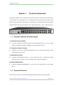
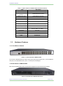
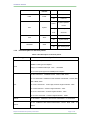
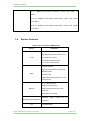
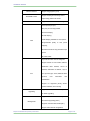
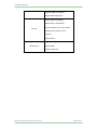
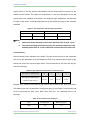
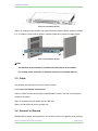
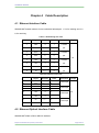
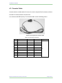
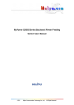
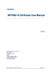
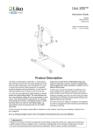
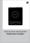
Installation Manual SM3300-28FX Installation Manual Maipu Communication Technology Co., Ltd No. 16, Jiuxing Avenue Hi-tech Park Chengdu, Sichuan Province People’s Republic of China - 610041 Tel: (86) 28-85148850, 85148041 Fax: (86) 28-85148948, 85148139 URL: http:// www.maipu.com Email: [email protected] Installation Manual All rights reserved. Printed in the People’s Republic of China. No part of this document may be reproduced, transmitted, transcribed, stored in a retrieval system, or translated into any language or computer language, in any form or by any means, electronic, mechanical, magnetic, optical, chemical, manual or otherwise without the prior written consent of Maipu Communication Technology Co., Ltd. Maipu makes no representations or warranties with respect to this document contents and specifically disclaims any implied warranties of merchantability or fitness for any specific purpose. Further, Maipu reserves the right to revise this document and to make changes from time to time in its content without being obligated to notify any person of such revisions or changes. Maipu values and appreciates comments you may have concerning our products or this document. Please address comments to: Maipu Communication Technology Co., Ltd No. 16, Jiuxing Avenue Hi-tech Park Chengdu, Sichuan Province People’s Republic of China - 610041 Tel: (86) 28-85148850, 85148041 Fax: (86) 28-85148948, 85148139 URL: http:// www.maipu.com Email: [email protected] Installation Manual Content Chapter 1 Product Introduction ............................................................................................................ 4 1.1 Product Features and Advantages ........................................................................................... 4 1.2 Physical Features .......................................................................................................................... 4 1.3 Hardware Features ........................................................................................................................ 5 1.3.1 Front Board of Switch ................................................................................................................... 5 1.3.2 Back Board of SM3300-28FX ...................................................................................................... 5 1.3.3 LED Indicators Instruction ............................................................................................................ 6 1.3.4 1.4 Port description on the front pannel ......................................................................................... 7 Service Features ............................................................................................................................ 8 Chapter 2 Preparations for Installation ............................................................................................. 11 2.1 Security Notice............................................................................................................................. 11 2.2 Examine Installation Location .................................................................................................. 11 2.2.1 Temperature/Humidity ................................................................................................................ 11 2.2.2 Neatness....................................................................................................................................... 12 2.2.3 Static Free .................................................................................................................................... 13 2.2.4 Anti-jamming ................................................................................................................................ 13 2.2.5 Anti-lightning................................................................................................................................. 14 2.3 Check Device and Accessories ............................................................................................... 14 2.4 Tools for Installation .................................................................................................................. 14 Chapter 3 3.1 Installation............................................................................................................................. 15 Preparing for Installation........................................................................................................... 15 3.1.1 Preparation Tool .......................................................................................................................... 15 3.1.2 Check the cabinet ........................................................................................................................ 15 3.2 Installation Step ........................................................................................................................... 15 3.3 Cable............................................................................................................................................... 16 3.3.1 Connect to Switch Console Port ................................................................................................ 16 3.4 Connect to Ground ..................................................................................................................... 16 3.5 Connect to Power ........................................................................................................................ 17 Chapter 4 Cable Description ................................................................................................................ 18 Maipu Confidential & Proprietary Information Page 2 of 21 Installation Manual 4.1 Ethernet Interface Cable ............................................................................................................ 18 4.2 Ethernet Optical Interface Cable ............................................................................................. 18 4.3 Console Cable .............................................................................................................................. 19 Chapter 5 Failure Handling .................................................................................................................. 20 5.1 Power System Failure ................................................................................................................ 20 5.2 Configuration System Failure .................................................................................................. 20 5.3 Failure Handling on No Displaying ......................................................................................... 20 5.4 Failure Handling on Displaying Invalid Characters ............................................................ 20 Maipu Confidential & Proprietary Information Page 3 of 21 Installation Manual Chapter 1 Product Introduction SM3300-28FX applies to various Ethernet access scenarios. Based on high-performance hardware of a new generation and the intelligent CPU, the SM3300-28FX provides abundant and flexible service features, ensuring operability, manageability, and expansibility. The SM3300-28FX withstands lightning strikes and bears excellent security features. It also supports strong RTCT、UDLD、Attack Prevention. 1.1 Product Features and Advantages 1. Powerful device stability Low power consumption and fanless make the switch working stably under -20℃-+50℃. Provide ports with 4 KV lightning protection capabilities. It supports FlexLink and LACP. 2. Complete network security It supports 2K L2-L4 basic/ extended/ self-defined ACL, 802.1x and MAC authentication, DHCP snooping and IP Source Guard. 3. Abundant Services It supports port-based/selective QinQ, 1:1 and N:1 VLAN Swap, up to 1k multicast group, IGMP Snooping v1/v2/v3, Fast-leave, Cross-vlan multicast, DHCP Option82 and PPPoE+ 4. Perfect Maintenance It supports SNMP/Telnet/SSH/WEB/VCT test, 802.3ah and Loopback detect, LLDP neighbor detect. 1.2 Physical Features The meaning of indicator in front board of SM3300-28FX Ethernet Switch is as in following table: Maipu Confidential & Proprietary Information Page 4 of 21 Installation Manual Table 1-1 System features of SM3300-28FX Fast Ethernet Switch Item Description Console RJ45,EIA/TIA-232 1000M Ethernet interface 1000M Ethernet SFP 1000M Ethernet SFP(SFP) 10G Ethernet SFP 10G Ethernet SFP(SFP) FLASH SDRAM Size (W×D×H) 1.3 1000M Ethernet port (RJ45) 16Mbytes 512Mbytes 440mm*280mm*44mm Weight <3KG Input voltage AC: 90~264V,47~67Hz Temperature -20℃-50℃ Humidity 10-90% Max power consumption ≤60W MTBF 80,000 hours Hardware Features 1.3.1 Front Board of Switch Picture 1-1 The front board of SM3300-28FX Front board of SM3300-28FX has 4*GE Combo ports (4*RJ-45 and 4*SFP ports ), 20*10/100Base-X SFP ports, 4*1G/10G Base-X SFP+ ports, 1 *Console port, 36*LED lights. 1.3.2 Back Board of SM3300-28FX Back board of SM3300-28FX switch includes power supply hub and ground wire end. As below: Picture 1-2 Back board of SM3300-28FX switch Maipu Confidential & Proprietary Information Page 5 of 21 Installation Manual 1.3.3 LED Indicators Instruction Front board light indicators of SM3300-28FX contain port indicators and system status indicators, the meanings of light indicators are the same, instruction as below: 1.3.3.1 Port Indicator Instruction Picture 1-3 SM3300-28FX LED Table 1-2 Port indicator instruction of SM3300-28FXSwitch Panel remark Indicator 1-4 (100M/1G Combo) Status Combo indicator Off Port links failure On Port links successful Flick 5-24(100M/1G) links successful, send or receive data Port links failure On Port links successful Flick Port LINK/ACT indicator Port Off Port LINK/ACT indicator 25-28 (1G/10G) Meanings Port links successful, send or receive data Off Port links failure On Port links successful Flick Port links successful, send or receive data 1.3.3.2 Status Indicator Instruction Picture 1-4 SM3300-28FX LED Table 1-3 Port indicator instruction of SM3300-28FX Indicator Maipu Confidential & Proprietary Information Panel Status Meaning Page 6 of 21 Installation Manual indicator PWR On Power on Off Power off Power System operation Flicker normal SYS System ALM Always System operation on/off abnormal On System Alarm Off System normal On Stacking state Off Non stacking state Alarm LOCATOR Stack 1.3.4 Port description on the front pannel Table1-4 Port description on the front pannel Port type Specification 100/1000Mbps Adaptive MDI/MDI-X Cable type auto adaptive RJ-45 Category 5 unshielded twisted pair(UTP) :100/1000M SFP of Combo ports support 100/1000Mbps auto adaptive SFP-SX-L transceiver:1000Base-SX SFP(850nm, MMF, 550m) SFP-LX-L transceiver:1000Base-LX SFP Interface Card Module(1310nm, SMF, 10km or MMF, 550m) SFP SFP-LX-20-L transceiver:1310nm light, 9/125um single-mode fiber:20km SFP-LX-40 transceiver:9/125um single-mode fiber:40km SFP-LH-70-L transceiver:9/125um single-mode fiber:70km SFP-LH-120-L transceiver:9/125um single-mode fiber:120km SFP-GT SFP-GT Module:1000Base-T SFP Interface Card Module,RJ-45 interface SFP-FX:100Base-FX SFP Interface Card Module(1310nm,MMF,2KM) ,LC SFP-FX interface Maipu Confidential & Proprietary Information Page 7 of 21 Installation Manual SFP-FL:100Base-FL SFP Interface Card Module(1310nm,SMF,15KM) ,LC interface SFP-FL-40:100Base-FL SFP Interface Card Module(1310nm,SMF,40KM) ,LC interface SFP-FL-80:100Base-FL SFP Interface Card Module(1550nm,SMF,80KM) ,LC interface 1.4 Service Features Table1-5 Service features of SM3300-28FX Service Realization 4K VLAN entries. Port-based and Protocol -based VLAN VLAN Port-isolation in a VLAN Port QinQ and selective QinQ 1:1 and N:1 VLAN switching 16K MAC address Aging time and add/remove static MAC MAC Black Hole MAC Port MAC Limit Disable MAC address learning on port or channel-group 2K L2 multicast groups IGMPv1/v2/v3 Snooping Multicast IGMP Filter/Fast leave/cross-VLAN duplication MLDv2/MLDv2 Snooping Broadcast packet number can be Broadcast storm suppression configured STP Maipu Confidential & Proprietary Information STP/RSTP/MSTP Page 8 of 21 Installation Manual Ethernet channel Support 8 aggregation group Support sending and receiving control Bandwidth control respectively, particle size is 64K Mirror Support interface and traffic mirroring 8 CoS queues per port; Per-port, per CoS drop profiles; Port level shaping; Q level shaping; Traffic shaping available on CPU queues; QoS Programmable priority to CoS queue mapping; Provide two levels of drop precedence per queue SP, WRR, DRR Up to 2K ACL items can be configured Support based on source MAC address, destination MAC address, source IP address, destination IP address, Layer 4 ACL port, protocol type, VLAN, Ethernet frame protocol, CoS information flow classification Support for tag-based priority stream packet redirection, flow mirroring Support Xmodem, FTP and TFTP protocol Upgrading to realize upgrading Supports MP.Link collection management and remote upgrading (client) Management Supports command-line interface(CLI) Support Telnet remote configuration Maipu Confidential & Proprietary Information Page 9 of 21 Installation Manual Supports SNMP management Support WEB management Support password gathering authentication of administrator Support interface lock, number of MAC Security address of each interface can be restricted. Support 802.1x Supports debug information output Maintenance Support PING Supports system log Maipu Confidential & Proprietary Information Page 10 of 21 Installation Manual Chapter 2 2.1 Preparations for Installation Security Notice To avoid device damaging and bodily injured caused by unsuitable operation, please follow these notices: Before cleaning switch, pull out the plug of switch. Do not wipe it with wet cloth and liquid. Do not locate switch near water or humid place, and prevent water and humidity entering switch. Do not locate switch on unstable case or desk. Falling may cause severe damage to switch. Keep the ventilation of the room and the switch. Switch can work normally under correct power pressure. Please affirm the power pressure of switch is the same as that marked. To avoid the danger of electricity attacking, do not open the cabinet shell though the switch is power off. 2.2 Examine Installation Location No matter where SM3300-28FX Fast Ethernet Switch is installed, in cabinet or on desk, following conditions must be satisfied. 2.2.1 Temperature/Humidity To guarantee normal working and life span of the switch, certain temperature and humidity can be maintained in the equipment room. If the humidity is too high, the insulating of insulating materialmay be not good, even creepage and sometimes may cause the change of mechanical performance and rustiness of metal parts. If the related humidity is low, the insulated gasket will be shrinkable which will cause the looseness of Maipu Confidential & Proprietary Information Page 11 of 21 Installation Manual captive screw. In the dry climate, electrostatics may be caused which is harmful for the CMOS circuitof switch. The higher the temperature is, the more dangerous it is.It will greatly reduce the reliability of the switch, and long-term high temperature will affect the life span of the switch. Overhigh temperature may accelerate the aging of the insulated materials. Table 2-1 The temperature and humidity requirements Temperature Humidity Long-term Short-term Long-term Short-term 15℃-30℃ 0℃-50℃ 40%-65% 10%-90% Note: 1. short-term means working no more than 48h less than 15 days a year; 2. The critical working environment means the possible temperature and humidity when there is no air-conditional. It should be recovered in 5h. 2.2.2 Neatness Dust is harmful for the operation of the switch. The dust in the room fell on the equipment may cause the absorption of the electrostatics, which may influence the life span of the switch and cause the communication failure. The requirement for the dust and the grin size is as following: Table 2-2 The requirement for the dust in switching room The maximum diameter(um) 0.5 1 3 5 The maximum thickness (the 7 1.4×10 5 7×10 5 2.4×10 5 1.3×10 3 number of grain per m ) Besides dust, switching room also strictly requires the content of salt, acid, and sulfide. This harmful gas may accelerate the rusting and aging of same parts. Such harmful gas must be prevented as SO2, H2O, NO2, NH3, and CL2. The restricted value is as following: Table 2-3 The limitation of harmful gas 3 3 Gas Average(mg/m ) Maximum(mg/m ) SO2 0.2 1.5 Maipu Confidential & Proprietary Information Page 12 of 21 Installation Manual H2S 0 0.03 NO2 0.04 0.15 NH3 0.05 0.15 Cl2 0 0.3 2.2.3 Static Free SM3300-28FX makes a lot of consideration in anti-static, but static electricity over a certain tolerance limit will disruptive the circuit even the whole switch. In the network connected by the switch, electrostatic induction mainly from two aspects: the outdoor high-voltage power lines, lightning and other external electric field; indoor environment, flooring materials, the whole structure of the internal system. In order to prevent electrostatic damage, we should: Equipment and floor ground connection; Anti-Indoor dust; Maintain proper temperature and humidity conditions; When touch the circuit board, user should wear anti-static wrist strap and overalls; The demolition of the circuit board face up on an anti-static working surface or an anti-static bag; Avoid direct touching circuit components. 2.2.4 Anti-jamming Switch may receive the jamming from exterior system. This jamming influences devices through capacitance coupling, inductance coupling, electromagnetic wave radiation, common impedance (including grounding system) coupling and conducting wire (power wire, cable and outputting wire). Pay attention to the followings: AC power supply uses TN system, and the plug adopts single-phase three-line power supply with protecting earth wire (PE) for filtering circuit to filtrate the jamming of electricity network. The location the switch works must be far away from high power wireless launcher, radar launcher and high frequency and current devices. Maipu Confidential & Proprietary Information Page 13 of 21 Installation Manual Adopts electromagnetism shield when necessary, such as adopting shield cable to be interface cable. 2.2.5 Anti-lightning SM3300-28FX makes a lot of consideration in anti-lightning, but lightning over a certain tolerance limit will disruptive the circuit even the whole switch. Users should: Ensure chassis is well connected to the ground AC power outlet is well connected to the ground 2.3 Check Device and Accessories Under the Confirm the required Installation environment, you can open the box. However, before the formal installation, you need to carefully check the packing list of the device within the box of equipment and accessories are complete. 2.4 Tools for Installation Tools needed: Cross screwdriver Antistatic wrist strap Wire stripper Cable needed: Power cable Console cable RJ-45 connector reticle Device needed: Configuration terminal (can be PC) Maipu Confidential & Proprietary Information Page 14 of 21 Installation Manual Chapter 3 Installation 3.1 Preparing for Installation 3.1.1 Preparation Tool Cross screwdriver Antistatic wrist strap Wire stripper Cable needed: Power cable Console cable RJ-45 connector reticle Device needed: Configuration terminal (can be PC) 3.1.2 Check the cabinet Switch can install in the 19” standard cabinet. Device should be installed in frame. Generally, one switch should install in one frame. 3.2 Installation Step Switch can install in the 19” standard cabinet. The process of installation is as following:: Step 1: Examine grounding and stability of the cabinet. Use screw to fasten hanger to the two sides of the front board and back board of the switch; Step 2: Locate switch on the salver of the cabinet. Move it to the suitable location along with the slide of the switch. Keep some space between switch and the slide. Step 3: Fasten hanger to the fixed slide of the cabinet to guarantee the bracket of each slot and hanger of the switch are fastened to the cabinet Maipu Confidential & Proprietary Information Page 15 of 21 Installation Manual Picture 3-1 Installation Picture Step 4: The hanger of the switch is not used to bear the load but fasten. Switch is installed in a 19” cabinet. There must be slides in chassis (fastened in frame) to support switch Picture 3-2 Installation Picture Note The heaviest device should be installed near the bottom of the cabinet. For cooling, there should be 1U distance between two installed devices. 3.3 Cable This chapter describes how to connect cable to switch. 3.3.1 Connect to Switch Console Port There is a EIA/TIA-232 console port on SM3300-28FX switch. User can use this port to configure the switch. Step1: A character terminal which can be a RS-232 Step2: Connect RS-232 port to console port 3.4 Connect to Ground SM3300-28FX Switch well-connected can protect switch from lightning and jamming, Maipu Confidential & Proprietary Information Page 16 of 21 Installation Manual user must correctly connect the ground carefully. AC switching power supply in the switch is connected with communication noise filter, which is directly connected to the chassis carefully, make induction, leakage electricity can safely into the earth, and improves overall EMI characteristics. For the external network connection, such as the E1 interface, PSTN and other cable series with the lightning voltage, ground can provide protection. Use a thick wire and connect the points with the earth, grounding resistance is less than 4 ohms. If the switch is installed in the cabinet, the cabinet also has to take the land required. 3.5 Connect to Power SM3300-28FX switch can support 100V and 240V with 50/60Hz AC power. Power input: (100~240VAC, 50~60Hz) 1: For AC, Step1: grounding connection Step2: Connect switch power outlet to the power socket Caution: Cut off the electricity before installing 48V power wire. The above operation with electricity is forbidden. Maipu Confidential & Proprietary Information Page 17 of 21 Installation Manual Chapter 4 Cable Description 4.1 Ethernet Interface Cable SM3300-28FX switch cable is 8-core unshielded twisted pair. 1, 2 is for sending and 3, 6 is for receiving. Table 4-1 RJ45 through line Cat5 RJ45 Signal Direction RJ45 Description 1 TX0+ —> 1 1 twisted 2 TX0- —> 2 pair 3 RX0+ <— 3 2 twisted 6 RX0- <— 6 pair 4 48V —> 4 3 twisted 5 48V —> 5 pair 7 0V <— 7 4 twisted 8 0V <— 8 pair Length 2m Table 4-2 RJ45 cross-wire Cat5 RJ45 Signal Direction RJ45 1 TX+ —> 3 2 TX- —> 6 3 RX+ <— 1 6 RX- <— 2 4 48V —> Description 1 twisted pair 2 twisted pair 7 3 twisted pair 5 48V 7 0V —> <— Length 2m 8 4 4 twisted pair 8 0V <— 5 4.2 Ethernet Optical Interface Cable SM3300-28FX fiber is SM or MM LC interface. Maipu Confidential & Proprietary Information Page 18 of 21 Installation Manual 4.3 Console Cable Console cable is a shield cable of 9 cores. One end is crimped RJ-45 connector, which is inserted to Console interface; the other end is a connector with DB-9 (holes). The Console cable is as the following picture: Picture 4-1 The picture of Console cable Table 4-3 Connecting of Console RJ45 Signal Direction DB9 1 CTS —> 8 2 DSR —> 6 3 RXD —> 2 4 GND --- 5 5 --- --- --- 6 TXD <— 3 7 DTR <— 4 8 RTS <— 7 --- --- 1 --- --- 9 Maipu Confidential & Proprietary Information Length 3m Page 19 of 21 Installation Manual Chapter 5 Failure Handling 5.1 Power System Failure SM3300-28FX Fast Ethernet Switch can check the power system failure according to the power indicator on the front board: when the power system works normally, the power indicator keeps on; if it is off, please examine as following: The correct connection of power wire. The matching of power supply of switch and power required. 5.2 Configuration System Failure After The power of SM3300-28FX Fast Ethernet Switch is on, if the system works normally, the booting information will be displayed in configuration terminal; if there is failure in configuration system, it will display nothing or illegible characters. 5.3 Failure Handling on No Displaying After the power is on, if the configuration terminal displays nothing, please examine the device as following: The power works normally. The correct connection of Console cable If there is no problem in above examination, maybe there is something wrong with the parameter configuration of the terminal (such as hyperterminal) or the configuration cable. 5.4 Failure Handling on Displaying Invalid Characters If illegible characters are displayed, parameter configuration of terminal (such as hyperterminal) is incorrect. Please affirm parameter Maipu Confidential & Proprietary Information Page 20 of 21 Installation Manual configuration of terminal (such as hyperterminal): baud rate is “9600”, data bit is “8”, and parity check is “none”, stop bit is “1”, flow control is “none”, and choose terminal emulation as “auto-detect”. Maipu Confidential & Proprietary Information Page 21 of 21