1
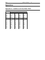
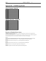
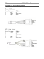
MoTeC PLM User’s Manual 1 PLM Professional Lambda Meter User’s Manual MoTeC PLM User’s Manual 2 Contents Meter Operation .............................................................. 3 Introduction..................................................................................................................... 3 Sensor Placement.......................................................................................................... 3 Connections .................................................................................................................... 3 Lambda............................................................................................................................ 3 Engine Tuning................................................................................................................. 3 Operating Tips ................................................................................................................ 4 Analogue Output............................................................................................................ 4 Initial Configuration........................................................................................................ 4 Warm-up Codes ............................................................................................................. 4 PLM Setup Software ....................................................... 5 Introduction..................................................................................................................... 5 Configurations................................................................................................................. 5 Changing the Configuration.......................................................................................... 6 Sensor.............................................................................................................................. 6 Display............................................................................................................................. 6 Output Table Setup........................................................................................................ 7 Analogue Output............................................................................................................ 7 Other Setup Features .................................................................................................... 7 Appendices .................................................................... 10 Appendix A - Lambda to Air Fuel Ratio Table.........................................................10 Appendix B – PLM Wiring Details .............................................................................11 Appendix C - Sensor Wiring Details..........................................................................12 Appendix D – PLM Warm-up Codes.........................................................................12 Appendix D – PLM Warm-up Codes.........................................................................13 Appendix E – PLM Diagnostic Codes.......................................................................14 Appendix F – Glossary................................................................................................15 Copyright 2001 – MoTeC Australia Pty Ltd The information in this document is subject to change without notice. No responsibility will be taken for the consequences of any inaccuracies occurring in this manual. 25 M ay, 2001 MoTeC PLM User’s Manual 3 Meter Operation Introduction The MoTeC Professional Lambda Meter measures Lambda (or Air Fuel Ratio) over a wide range of mixtures with fast response time. The display may be set to Show Lambda, Air Fuel Ratio (for Petrol, Alcohol, Gas, Diesel or ‘blend’ fuel) or equivalence ratio. The PLM provides an Isolated Analogue Output Voltage proportional to Lambda that may be connected to an Analogue Meter or other measurement instrument such as a Data Logger or dynamometer. The PLM also supports a CAN data link to devices such as the Motec Dash Logger for transmission of sensor and diagnostic data. Sensor Placement The sensor should be fitted to the exhaust system and the sensor tip protrude into the exhaust gas flow. When fitted it should be tilted at an angle of between 10 and 90 degrees to the horizontal, ie: with the tip of the sensor pointing down. This is to ensure that no condensed water builds up between the sensor case and the sensor ceramic. It is recommended that where possible the sensor be placed at least 1m from the exhaust ports to avoid excessive heat and at least 1m from the open end of the exhaust system to avoid incorrect readings due to outside oxygen. This is however not mandatory, and where necessary for shorter exhaust systems the sensor should be placed closer to the engine. Connections The PLM has two D-9 pin connectors. The loom supplied with the PLM is fitted to the male connector. This is for connection to the sensor and to a power supply. The 2 pin DTM connector is connected to a 12V DC power supply. The Power supply must provide current for both the Meter and the Sensor Heater Element. This can be up to 5 Amps at start up. The vehicle battery is usually the most convenient source of power. The PLM can be connected to a PC for configuration by using the second, female D-9 connector. This connector also has pins for the CAN data bus, digital inputs and analogue voltage output. See Appendix B for a description of the PLM pinout. Lambda Lambda gives a measure of Air Fuel Ratio that is independent of the type of fuel being used. Lambda 1.0 corresponds to the stoichiometric ratio i.e. when there is no excess fuel and no excess air. Lambda > 1.0 => Excess Air (Lean) Lambda < 1.0 => Excess Fuel (Rich) Lambda may be directly converted to Air Fuel Ratio for a specific fuel using a multiplication factor. The PLM will display Air Fuel Ratio by loading the appropriate configuration into one of the output tables. This is described below in the section PLM Setup Software | Output Table setup. A table to convert Lambda to Air Fuel Ratio for various fuels is given in Appendix A. Engine Tuning The desired Air Fuel Ratio (or Lambda) is dependant on the tuning objective i.e. Power, Economy or Emissions. Normally at Full Load the Engine is tuned for maximum power and at light loads the engine is tuned for emissions or economy. The following table gives a guide to the required Lambda values for different tuning objectives. MoTeC PLM User’s Manual Objective Lambda Power 0.84 to 0.90 Economy 1.05 Emissions 1.00 Note Note 4 The exact requirements for a specific engine and fuel must be found by experimentation. On Turbo Engines extra fuel may be desirable to reduce exhaust temperatures and help avoid knock. Operating Tips If the Engine misfires for any reason including an over-rich mixture the Meter may falsely read Lean. This is due to excess air being present in the exhaust gasses which is caused by incomplete combustion when the engine misfires. Engines with high overlap camshafts running at low speed may pump air through the engine resulting in a false lean reading, therefore the meter may need to read leaner than would otherwise be expected. Analogue Output The Analogue Output provides a voltage proportional to Lambda. The default configuration is set for 0 – 5 V to correspond to 0.5 to 1.5 Lambda. This scaling can be changed by using the PLM Setup software. Details are given in the section Configuration | Analogue Output below. For correct operation Aout- MUST be connected to the ground reference on the monitoring system. Initial Configuration The PLM is initially programmed with a configuration that will allow it to operate as a stand alone device. It will automatically detect the sensor type and display the lambda reading. This configuration will also transmit data to an ADL when the CAN bus pins are connected to the ADL as described in Appendix B. The analogue output is initially configured with a 0 – 5 V output corresponding to 0.5 to 1.5 Lambda. Making changes to the configuration The PLM need only be connected to a PC if the user wishes to change the display type, the analogue output calibration or modify the configuration in some other way. Warm-up Codes Upon being powered up, the PLM will display the current version of software for about one second. It will then display a series of codes describing the warm-up progress. A description of these codes is given in Appendix D. MoTeC PLM User’s Manual 5 PLM Setup Software Introduction Computer Requirements: The Personal Computer (PC) must be an IBM PC compatible running Windows95, 98, ME, NT4 or Windows2000 operating system. Recommended Minimum specifications Pentium 90, 16 MB RAM Serial Port The PLM connects to the PC with a standard serial communication cable. This is also known as a 'straightthough' cable. Installing PLM Setup Place the floppy disk in the ‘A’ drive. Click on the Windows 'Start' button and select Run. Type a:\setup.exe Follow the setup program instructions To start the program after installation, click on the Windows 'Start' button, and select 'Programs --> Motec --> PLM Setup --> PLM Setup 1.0' Mouse and Keyboard The PLM setup software may be operated using the keyboard or a mouse. It is often easier and faster to use the keyboard on many Notebook (laptop) PC's. Main Menu The main menu is used to access all of the functions of the PLM setup software. Click the mouse on one of the menu items, or press the Alt key together with the underlined letter. Eg: press Alt + S for the Setup menu. When the PLM Setup software is started, a configuration file needs to loaded before changes can be made. This can be from a file on disk, or from the PLM itself. Configurations The PLM configuration determines exactly how it operates. The initial configuration will display Lambda when the PLM is powered and connected to a sensor. Changes can be made to the configuration to alter various aspects of the PLM. This includes: the display parameter (eg: to A/F ratio), modifying the scaling of the analogue output, sensor type, backlight intensity, etc. Standard configuration templates for most common preferences are included. Configuration Files The configuration files are stored on the PC hard disk and can be modified before being sent to the PLM. A new configuration can be created by selecting File | New from the main menu. After a configuration has been created or modified it should be saved with a meaningful name by selecting File | Save from the main menu. Opening an Existing File Before an existing configuration can be modified or sent to the PLM it must first be opened. To open a configuration file select File | Open from the main menu and select the desired file. Note that the most recently used files appear at the bottom of the File menu, which is often the easiest way to open a recently used file. MoTeC PLM User’s Manual 6 Connecting to the PLM A PC can be connected to the PLM with a serial cable running directly from a PC serial port to the female D-9 connector on the PLM. The serial port used can be selected from the Options | Communications Port item from the main menu. Sending and Retrieving Configurations The currently open configuration file can be sent to the PLM by selecting Online | Send Configuration from the main menu. When a configuration file is sent to the PLM any changes are automatically saved to the file. The configuration can be retrieved from the PLM by selecting Online | Get Configuration from the main menu. It is advisable to Get the initial configuration from the PLM and save this before making modifications. Changing the Configuration Once an existing configuration file has been opened, or a new one created the various parts of the configuration may be modified by choosing the appropriate items from the main menu. The configuration setup items are accessed from the main menu item Setup | Sensor, Display, Analogue Outputs Sensor Sensor Type The user can manually select the sensor used as Bosch LSU or NTK Uego. Selecting ‘Auto’ allows the PLM to determine the type of sensor being used. Calibration Method There are several options available for choosing the calibration method of the sensor being used. The default option for this is ‘Use measured calibration value’. This allows the PLM to determine the sensor calibration and can be used in most cases. If the calibration value of the sensor is known then it can be entered by selecting the second choice – ‘Enter calibration value’. This value is engraved on LSU sensors supplied by MoTeC. The other two methods are for advanced users and will not generally need to be used. Heater Control This allows the heater voltage to be set when using an NTK sensor. Again this is an option for advanced users and should be left at 10.5 volts (default value) by most users. Display This screen allows the user to set the parameters for the lambda meter display screen. The display update rate and filtering values are independent of the real values used for CAN and analogue voltage outputs. Output to display The user can choose the output to display from one of the two output tables. Decimal Places Selectable from 0 to 3. Normal use would be to 2 decimal places for lambda. Update Rate Displayed value will update from 1 to 10 times a second. Filter Time The data can be filtered so that it is more stable and easier to read. This is independent of the update rate. MoTeC PLM User’s Manual 7 Backlight Intensity User definable from 0 to 100%. Output Table Setup The Output Tables are used by the PLM to calculate the displayed value. The PLM stores two tables that can be configured with different calibrations for displaying lambda, air fuel ratio or equivalence ratio. In addition to a lambda calibration, there are a number of pre-defined calibrations for air fuel ratio for different fuels. To display one of these, the calibration must be loaded from the PC by clicking on the ‘Load’ button and choosing the appropriate calibration from the list displayed. Advanced users can generate their own calibration tables using the Ipn1 value measured by the meter. These can be saved for re-use. Analogue Output The PLM is capable of generating an analogue voltage based on the measured lambda value. This can be connected to another device, such as an ECU, data logger or dynamometer, allowing it to read the measured lambda value. The type of value to be generated can be selected from the drop down list. This then appears in the ‘Input’ column of the Calibration Table. Calibration Table The calibration table allows users to set the voltage output that corresponds to the table input value. The table takes the input value and translates it to an analogue voltage by way of the calibration table. The output voltage can be in the range of 0 to 5 volts. At least two pairs of values must be entered in the table, so that a straight line may be derived between the two points. The voltage is linearly interpolated between points in the table. Once created, tables can be saved and then used in other configurations. Other Setup Features Digital Inputs The PLM has two digital inputs, with two possible functions. Input 1 can be used to read engine RPM, and this value is then transmitted on the CAN data stream. The other function is to use an input to switch the unit on/off. The operate condition to enable the PLM can be based on either input. This way the PLM can be set to operate only when measuring RPM, or when a switch is set. CAN Messages The PLM is pre-configured to send CAN data to a MoTeC ADL. See Appendix B for details of wiring the PLM to an ADL. The data to be transmitted can be the value from either output table 1 or 2. Users should only change the Address or Compound ID, when connecting to a CAN device other than the ADL. Dash Manager Setup Under Inputs | Communications click on one of the blank CAN inputs. Then select template PLM #1 (CAN ID 460). The channels available are then listed under Received Channels. 1 Normalised sensor pump cell current MoTeC PLM User’s Manual 8 Specifications Meter Power Supply Input Voltage Range Input current Protection Load Dump Clamp 7 to 16Volts 60mA Typical backlight off 110mA Typical backlight on Plus sensor heater current Reverse polarity protected Max 40V at 100 Amp 100msec Sensors Sensors Compatible Types Calibration Methods Type Detection Sensor Thread 1 Bosch LSU / NTK UEGO Automatic using sensor’s built in calibration resistor Manual Table Entry Known Oxygen Environment Calibration Constant Manual or Automatic (using sensor’s built in calibration resistor) M18 x 1.5 Measurements Lambda 02 A/F Ratio Accuracy 0.7 to 32.0 0 to 22% Fuel dependant (see lambda range) +-1.5% (sensor specific) Sensor Heater Outputs Current Control 1 Max 8 Amp Bosch - Digital PID NTK - Constant Voltage NTK sensor requires at least 11V for proper operation of heater Output Analogue Output Type Common Mode Range 0 - 5V DC Max, User Programmable Floating -4.5 to 5.0 volts Inputs Digital 2 x User Programmable as RPM or PLM Enable (Operate) Communications Serial CAN @ up to 1Mbit RS232 Display Type Digit Height Lighting LCD 3.5 Digit 12.7mm Green LED Back Light Processor CPU Speed Motorola 68HC908AZ60 8MHz MoTeC Code Memory Configuration Memory PLM User’s Manual 60K Flash 1K EEPROM Field updateable Connection Connectors 2 x 9 Pin Dsub (commonly called D9) Environment Temperature Range -10 to 70 Deg C Case Dimensions(WxHxD) Weight 105x41x25 mm (Excluding Connector) 135grams 9 MoTeC PLM User’s Manual 10 Appendices Appendix A - Lambda to Air Fuel Ratio Table Lambda 0.70 0.75 0.80 0.85 0.90 0.95 1.00 1.05 1.10 1.15 1.20 1.25 1.30 1.35 1.40 1.45 1.50 1.55 1.60 Air Fuel Ratio Petrol 10.3 11.0 11.8 12.5 13.2 14.0 14.7 15.4 16.2 16.9 17.6 18.4 19.1 19.8 20.6 21.3 22.1 22.8 23.5 Alcohol 4.5 4.8 5.1 5.4 5.8 6.1 6.4 6.7 7.0 7.4 7.7 8.0 8.3 8.6 9.0 9.3 9.6 9.9 10.2 LPG 10.9 11.6 12.4 13.2 14.0 14.7 15.5 16.3 17.1 17.8 18.6 19.4 20.2 20.9 21.7 22.5 23.3 24.0 24.8 Diesel 10.2 10.9 11.6 12.3 13.1 13.8 14.5 15.2 16.0 16.7 17.4 18.1 18.9 19.6 20.3 21.0 21.8 22.5 23.2 MoTeC PLM User’s Manual 11 Appendix B – PLM Wiring Details Sensor Connector - Male D9 1 2 3 4 5 6 7 8 9 Battery +12 Power (Note 2) Heater + Rc Ip Sensor Common Battery 0V Power Heater – Vs Ipr Auxiliary Connector – Female D9 1 2 3 4 5 6 7 8 9 CAN Hi (Note 3) RS232 Tx RS232 Rx Digital Input 1 Comms 0V CAN Lo (Note 4) Digital Input 2 Analogue out + (Note 5) Analogue out – (Note 6) Note1: Extension of Standard Sensor Loom The length of the standard loom supplied for connection of the PLM to a sensor is 2.5m. Longer looms are available from MoTeC by request. It is not recommended that the loom is extended by using a standard serial cable. These are unable to supply the current required by the sensor. If an extension is made, the wire must be at least 20 gauge. Note 2: If using a power supply other than the vehicle battery, start-up current for the sensor is up to 5A, though operating current is much lower than this, 0.5 – 1 Amps, depending on exhaust gas temperature. Note 3: For connection to an ADL, wire to pin 74 or 76. Can be spliced into an existing wire. Note 4: For connection to an ADL, wire to pin 73 or 75. Can be spliced into an existing wire. Note 5: Connect the Positive wire to the positive input on the measuring device. Note 6: Connect the Negative wire to the 0V reference point on the measuring device. MoTeC PLM User’s Manual Appendix C - Sensor Wiring Details Bosch LSU Sensor Sensor Pin Colour PLM pin 1 2 3 4 5 6 Ipr Vs Sensor Common Heater + Heater Ip Red Black Yellow White Grey NTK – Uego Sensor Sensor Pin Colour PLM pin 1 2 3 4 5 6 7 8 2 Heater + 7 Heater Rc Sensor Common N/C Vs Ip Sensor Common Orange Yellow Red White Black 12 MoTeC PLM User’s Manual Appendix D – PLM Warm-up Codes C-6 C-5 C-4 C-3 C-2 C-1 Sensor Protection Shutdown User Stop No Heater detected Warm Up Control Initialization Checking Operation 13 MoTeC PLM User’s Manual Appendix E – PLM Diagnostic Codes These are the diagnostic error groups that are sent to the ADL via the CAN link. Diagnostic Group 1 1 : No Sensor 2 : Sensor Hot 4 : Sensor Cold 8 : Sensor Faulty 16 : Heater Drive Overload 32 : Warm Up 64 : Ref voltage out of range Diagnostic Group 2 These codes are the same as those displayed by the PLM. 1 (C-1) - Checking Operation. 2 (C-2) - Control Initialization. 4 (C-3) - Warm Up. 8 (C-4) - No heater detected. 16 (C-5) - User Stop. 32 (C-6) - Sensor Protection Shutdown. 14 MoTeC PLM User’s Manual 15 Appendix F – Glossary CAN – Controller Area Network. High speed serial data bus common in automotive applications Ip – Sensor pump cell current Ipn – Normalised Ip Vs – Sense voltage