1
Tension Control Inverter
MD330
User Manual
VER:0.0
Contents
Chapter 1 Overview ..............................................................................1
Chapter 2 Tension Control Principles....................................................2
2.1 Schematic diagram for typical curling tension control.............2
2.2 Tension control scheme..........................................................3
Chapter 3 Function Parameter Table ....................................................7
Chapter 4 Parameter Description ....................................................... 20
4.1 Selection of Control Mode .................................................... 20
4.2 Tension setting ..................................................................... 23
4.3 Curling radius calculation ..................................................... 25
4.4 Line speed input ................................................................... 30
4.5 Tension compensation.......................................................... 32
4.6 PID parameters .................................................................... 35
4.7 Auto roll alternation parameter ............................................. 38
4.8 Additional parameters........................................................... 39
Chapter 1 Overview
Chapter 1 Overview
This manual shall be used together with the MD320 User Manual. This
manual only describes the parts related to curling tension. Other basic
functions are described in MD320 User Manual.
When the tension control mode is set as inactive, the inverter has the
same functions are the MD320.
MD330 is used for curling control. It can automatically calculate the
curling radius and is able to realize constant tension when the curling
radius changes. To realize constant torque control in the applications
without curling radius change, MD320 inverter is recommended.
When the tension control mode is selected, the output frequency and
torque of the inverter will be automatically generated by the tension
control function, and the frequency source selection in group F0 will be
inactive.
1
Chapter 2 Tension Control Principles
Chapter 2 Tension Control Principles
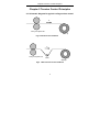
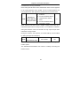
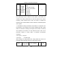
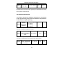
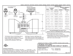
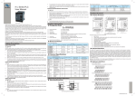
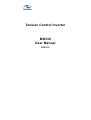
2.1 Schematic diagram for typical curling tension control
F
Carry-over pinch roll
Wind up
Fig.1 without tension feedback
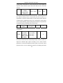
F
Carry-over pinch roll
Fig.2
Float
Wind up
With float roll tension feedback
2
Chapter 2 Tension Control Principles
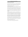
2.2 Tension control scheme
There are two ways for tension control:
to control the output torque of
the motor and to control the rotation speed of the motor. MD330 is
designed with two tension control modes for the two methods.
1. Open-loop torque control mode
Open loop means that there is no tension feedback signal, and the
inverter can realize the control through the output frequency or torque
only, which will not be affected if the inverter is in open loop vector
mode or close loop vector mode. The torque control mode means that
the inverter controls the motor’s torque rather than its frequency, and
the output frequency changes automatically following the speed of the
materials.
According to the formula F=T/R (where: F is the material tension, T is
the torque of the wind-up roll, R is the curling radius), if the torque of the
wind-up roll can be adjusted based on the change of the curling radius,
the tension of the materials can be controlled. This is the principle for
tension control in open loop torque mode. The reason for its feasibility is
that the tension of the material is from the torque of the wind-up roll only,
and the torque of the wind-up roll is mainly imposed on the materials.
The MD series inverter can correctly control the output torque of the
motor in closed loop vector mode (with speed sensor vector control).
However, to use this control mode, encoder must be installed (the
inverter shall be equipped with PG card).
2. Function modules related to open loop torque mode
3
Chapter 2 Tension Control Principles
1) Tension setting part: It is used to the set the tension. In practice, the
set value of the tension shall correspond to the actual situations, such
as the materials used and the curling requirements. The relevant value
shall be set by the user. The tension taper can control the tension to
decrease with the increase of the curling radius, so as to improve the
curling effect.
2) Curling radius calculation part: It is used to calculate or acquire the
curling radius information. If line speed is used to calculate the curling
radius, the line speed input function part is needed. If thickness
accumulation is used to calculate the curling radius, the relevant
function part for calculating curling radius with thickness accumulation
shall be used.
3) Torque compensation part: Part of the output torque of the motor will
be used to overcome the rotation inertia of the wind-up/roll-down roll
during the acceleration/deceleration. The inertia compensation part of
the inverter can be automatically compensated automatically according
to the acceleration/deceleration rate through proper parameter setting,
so that the system can still have stable tension during the
acceleration/deceleration. The friction compensation can eliminate the
influence of the system resisting force over the tension.
3. Close-loop speed control mode
Close loop means that the tension (position) detection feedback signal
forms a close loop for adjustment. Speed control mode means that the
inverter realizes the control by adjusting the output frequency according
to the feedback signal. The inverter under speed mode can operate in
4
Chapter 2 Tension Control Principles
any of the following three modes: speed sensorless vector control,
speed sensor vector control, and V/F control.
The principle for the control mode is as follows: calculate a set value for
the matching frequency, f1, according to the material line speed and the
actual curling radius, conduct PID operation through the tension
(position) detection signal to generate a frequency adjustment value f2,
and then output the final frequency f=f1+f2. f1 can basically match the
line speed of the wind-up/roll-down roll with the material line speed, and
then the control requirement can be met with the slight adjustment of f2.
In this way, the problem between the response quickness and the
control stability in close-loop control can be well solved.
In this mode, the tension setting part is inactive, and the target value of
the system control is set in the FA-00PID reference source. The control
result is that the tension (position) feedback signal will be the reference
value of the PID. It should be noted that when using the position signal
(e.g. tension swing, float roll) as the feedback, the actual tension may
not be changed by changing the set value (PID reference value). The
mechanical configuration, such as the counterweight of the tension
swing or float roll, shall be changed to change the tension.
4. Function modules related to close loop speed mode
1) PID part: It is mainly used for setting of group FA. It can also provide
auxiliary function for the second group of PID parameters in group FH.
After all the other parts are correctly set, the PID parameters shall be
adjusted for the final control result.
2) Line speed input part: This part is very important. It has two functions:
5
Chapter 2 Tension Control Principles
to calculate the matching frequency according to the line speed (as
described above) and to calculate the curling radius through the line
speed.
3) Curling radius calculation part: It is used to calculate the actual
curling radius. The inverter can acquire the matching frequency after
obtaining the line speed and the actual curling radius. When using the
line speed to calculate the curling radius, if the curling radius calculated
by the inverter is different from the actual curling radius, it indicates that
there is deviation in the line speed input. The line speed input can be
corrected through the curling radius calculation result. It should be
noted that the matching frequency calculated with the line speed and
the curling radius is not the actual output frequency of the inverter, while
operating frequency used in calculating the curling radius with the line
speed and operating frequency is the actual output frequency of the
inverter. There is no contradiction in logic.
4) The second group PID parameter part: Only one group of PID
parameters is not sufficient for the whole process control. At this time,
the second group of PID parameters can be used. For example, during
partial wind-up, the first group of PID parameters can be used to
achieve good control result; during full wind-up, the second group of
PID parameters can be used to achieve good control result. In this way,
good control result can be achieved in the whole process.
6
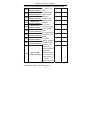
Chapter 3 Function Parameter Table
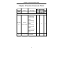
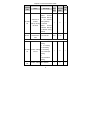
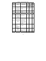
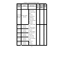
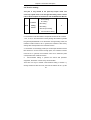
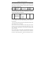
Chapter 3 Function Parameter Table
Function
code
Mini
Name
Set range
Leave-fa
mum ctory set
Chan
ge
unit
value
1
0
×
1
0
○
Control mode selection
0: inactive
1: Open-loop
torque control
mode
2: Close-loop
FH-00FH
Tension
-00
control mode
speed control
mode
3: Close-loop
torque control
mode
4: Constant line
speed control
mode
FH-01FH
-01
Curling mode
0: wind-up
1: roll-down
7
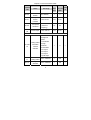
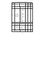
Chapter 3 Function Parameter Table
Function
code
Mini
Name
Set range
Leave-fa
mum ctory set
Chan
ge
unit
value
1
0
○
0.01
1.00
○
1
0
×
1
0
×
0: Not allowed
Active
inverse
material take-up
Selection of
FH-02FH
-02
inverse
is
not
allowed
during startup
take-up during 1: allowed
roll-down
Active
inverse
material take-up
is allowed during
startup
mechanical
FH-03
transmission
0.01~300.00
ratio
Tension setting part
0: FH-05
setting
1: AI1 setting
2: AI2 setting
FH-04FH Tension setting 3: AI3 setting
-04
source
4: PULSE input
setting
5:
communication
setting
FH-05FH
-05
Tension setting 0N~30000N
8
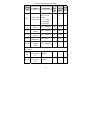
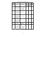
Chapter 3 Function Parameter Table
Function
code
FH-06
Mini
Name
maximum
tension
Set range
Leave-fa
mum ctory set
Chan
ge
unit
value
0N~30000N
1
0
×
0.0%~50.0%
0.1%
0.0%
○
1%
0%
○
0.1%
0.0%
×
1
0
×
1mm~10000mm
1
500
×
1mm~10000mm
1
100
×
Zero-speed
FH-07
tension
increase
FH-08
FH-09FH
-09
zero-speed
threshold
tension taper
0.0~20%
( maximum
frequency)
0.0%~100.0%
Curling radius calculation part
0: calculation
through line
speed
curling radius
FH-10FH
calculation
-10
method
selection
1: Calculation
through
thickness
accumulation
2: AI1 input
3: AI2 input
4: AI3 input
5: pulse input
FH-11FH
maximum
-11
curling radius
FH-12
winding shaft
diameter
9
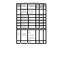
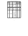
Chapter 3 Function Parameter Table
Mini
Function
Name
code
Set range
Leave-fa
mum ctory set
Chan
ge
unit
value
1
0
×
1mm~10000mm
1mm
100mm
○
1mm~10000mm
1mm
100mm
○
1mm~10000mm
1mm
100mm
○
0.0s~100.0s
0.1s
1.0s
○
---
---
○
0:
FH-12~FH-15
FH-13
initial curling
setting
radius source
1: AI1 setting
2: AI2 setting
3: AI3 setting
FH-14FH
initial curling
-14
radius 1
FH-15
FH-16
FH-17
initial curling
radius 2
initial curling
radius 3
curling radius
filtering time
current value
FH-18
of curling
1mm~10000mm
radius
Relevant parameters for curling radius calculation with thickness
accumulation
FH-19FH
-19
Number of
pulses each
1~60000
1
1
○
1~10000
1
1
○
turn
Number of
FH-20
turns each
layer
10
Chapter 3 Function Parameter Table
Function
code
Mini
Name
Set range
1: AI1 setting
thickness
setting source
FH-22FH
Material
-22
thickness 0
FH-23
FH-24
FH-25
FH-26
mum ctory set
Chan
ge
unit
value
1
0
○
0.01mm
○
0.01mm
○
0.01mm
○
0.01mm
○
1.00mm
○
0
○
0: Digital setting
Material
FH-21
Leave-fa
2: AI2 setting
3: AI3 setting
0.01mm~100.00
0.01
mm
mm
0.01mm~100.00
0.01
mm
mm
0.01mm~100.00
0.01
mm
mm
0.01mm~100.00
0.01
mm
mm
maximum
0.01mm~100.00
0.01
thickness
mm
mm
Material
thickness 1
Material
thickness 2
Material
thickness 3
Line speed input part
0: No input
1: AI1
2: AI2
FH-27FH
line speed
-27
input source
3: AI3
4: pulse input
1
5:
communication
setting
FH-28FH
-28
maximum line 0.10m/Min~6500. 0.1m/ 1000.0m/
speed
0m/Min
11
Min
Min
○
Chapter 3 Function Parameter Table
Function
code
Mini
Name
Set range
Leave-fa
mum ctory set
unit
value
Chan
ge
minimum line
FH-29
speed for
curling radius
0.10m/Min~6500. 0.1m/
0m/Min
Min
0.10m/Min~6500.
――
200.0m/
Min
○
calculation
FH-30
Actual line
speed
―――
○
0.1%
20.0%
○
1
0
○
1
0
○
0Kg/m^3
○
0mm
○
0m/Min
―
Tension compensation part
compensation
FH-31FH
coefficient self
-31
learning torque
5.0%~80.0%
setting
0: no operation
compensation
FH-32
self learning
action
1: Start to identify
automatically
restore to 0 when
the self learning
is ended.
mechanical
FH-33FH inertia
-33
compensation
1~10000
coefficient
FH-34
FH-35
material
density
0
Kg/m^3~60000K
g/m^3
material width 0mm~60000mm
12
1Kg/
m^3
1mm
Chapter 3 Function Parameter Table
Function
code
Mini
Name
Set range
Leave-fa
mum ctory set
unit
value
0.1%
0.0%
Chan
ge
friction
FH-36
compensation 0.0%~50.0%
○
coefficient
material supply interrupt auto detection parameters
material supply
FH-37FH
-37
interrupt auto
detection
function
0: inactive
1: active
1
0
×
10.00Hz
○
selection
material supply
FH-38FH
-38
interrupt auto
detection
0.00Hz~50.00Hz
minimum
0.01H
z
frequency
material supply
FH-39
interrupt auto
detection error
0.1%~50.0%
0.1%
10.0%
○
0.1s~60.0s
0.1s
2.0s
○
0.1
20.0
○
0.01s
2.00s
○
range
material supply
FH-40
interrupt auto
detection
judgment delay
the second group of PID parameters
FH-41FH
proportional
-41
gain 2
FH-42
0.0s~100.0s
integral time I2 0.01s~10.00s
13
Chapter 3 Function Parameter Table
Function
code
FH-43
Mini
Name
Set range
mum ctory set
unit
differential time
D2
Leave-fa
0.001
0.000s~1.000s
value
Chan
ge
0.000s
○
0
○
0.1%
0.0%
○
1
0
○
0.1%
0.0%
○
s
0: Only the first
group of PID
parameters are
used
1: Adjust
auto
FH-44
adjustment
basis for PID
parameters
according to the
curling radius
1
2: Adjust
according to the
operating
frequency
3: Adjust
according to the
line speed
Auto roll alternation parameter
FH-45FH
pre-drive
-45
speed gain
pre-drive
FH-46
torque limit
selection
FH-47FH
pre-drive
-47
torque gain
-50.0%~+50.0%
0: F2-09 setting
1: Set the limit
according
to
tension setting
-50.0%~+50.0%
14
Chapter 3 Function Parameter Table
Function
code
Mini
Name
tension taper
FH-48
source
selection
Set range
Leave-fa
mum ctory set
Chan
ge
unit
value
1
0
○
0.0%~100.0%
0.1%
50.0%
○
0.0%~100.0%
0.1%
0.0%
○
-50.0%~+50.0%
0.1%
0.0%
○
1
0
○
1
0
○
0: FH-09 setting
1: AI1 setting
2: AI2 setting
3: AI3 setting
tension close
FH-49FH
loop control
-49
adjustment
limit
tension close
FH-50
loop control
adjustment
limit offset
high-speed
FH-51
torque
compensation
coefficient
FH-52
compensation 0: frequency
basis
1: line speed
external taper 0:
FH-53
control
maximum
FH-54
setting
1: AI1 setting
output setting
2: AI2 setting
source
3: AI3 setting
15
Chapter 3 Function Parameter Table
Function
code
Mini
Name
Set range
Leave-fa
mum ctory set
Chan
ge
unit
value
0.1%
100.0%
○
1
0
○
0.0s~10.0s
0.1s
5.0s
○
0.0%~200.0%
0.1%
50.0%
○
1
0
○
1mm
0
○
external taper
control
FH-54
maximum
0.0%~100.0%
output digital
setting
pre-drive
FH-55
curling radius
calculation
selection
0: calculate
1: stop
calculation
curling radius
FH-56FH
-56
calculation
stop delay
after ending of
pre-drive
FH-57
tension
increase ratio
0: AI1 setting
1: AI2 setting
FH-58
line speed
setting source
2: AI3 setting
3: pulse setting
4:
communication
setting
taper
FH-59
compensation 1mm~10000mm
correction
16
Chapter 3 Function Parameter Table
Function
code
Mini
Name
Set range
Leave-fa
mum ctory set
unit
value
1
0
Chan
ge
tension taper
FH-60
effectiveness
0: taper effective
selection for
1: taper
close loop
ineffective
tension control
input/output selection
F7-04F704
operation
display
selection
BIT13: curling
radius
BIT14: tension
setting
BIT10: tension
setting
BIT11: curling
radius
When switching
F7-05F7-
stop display
05
selection
to display the
curling radius
during the stop,
the curling radius
can be changed
by the UP/DOWN
terminal or
relevant button.
17
○
Chapter 3 Function Parameter Table
Function
code
Mini
Name
Set range
Leave-fa
mum ctory set
unit
value
Chan
ge
12: external taper
control output
13: curling radius
output:
F5-07~F5
-09F5-07
~F5-09
analog output
selection
0%~100%
corresponds to
0~maximum
curling radius
14: actual tension
(after taper
calculation)
F4-00F400
F4-01
F4-02
F4-03
DI1 terminal
×
function
reset
selection
32: initial curling
DI2 terminal
radius selection
function
terminal 1
selection
33: initial curling
DI3 terminal
radius selection
function
terminal 2
selection
34: Pre-drive
DI4 terminal
input terminal
function
35: turn counting
selection
signal
DI5 terminal
F4-04
31: curling radius
×
×
×
36: Torque
function
memory
selection
37: torque
18
×
Chapter 3 Function Parameter Table
Function
code
Mini
Name
Set range
Leave-fa
mum ctory set
unit
value
Chan
ge
DI6 terminal
F4-05
×
function
selection
DI7 terminal
F4-06
function
×
selection
DI8 terminal
F4-07
×
function
selection
DI9 terminal
F4-08
function
×
selection
DI10 terminal
F4-09
function
×
selection
19
Chapter 4 Parameter Description
Chapter 4 Parameter Description
4.1 Selection of Control Mode
0: inactive
1: Open-loop torque control
mode
FH-00
Tension
control mode
2: Close-loop speed control
0
mode
3: Close-loop torque control
mode
4: Constant line speed
control mode
1. Select the tension control mode with the parameter
1) Don’t choose tension control mode. The tension control is inactive,
and the inverter is used as general inverter.
2) Open-loop torque control mode: No tension test and feedback is
required. The inverter controls the tension of the material through
controlling output torque. The output torque controlled by inverter can
realize better control under the speed sensor vector control.
3) Close-loop speed mode: Tension test and feedback are required.
The inverter controls output frequency through PID close-loop to enable
the set tension is met. The inverter controls output frequency through
speed sensorless vector control, V/F control or close-loop vector
control.
4) Close-loop speed mode: Tension test and feedback are required.
20
Chapter 4 Parameter Description
The inverter controls output torque through PID close-loop to enable
the set tension is met. The inverter controls output torque through
close-loop vector control mode (with speed sensor vector control).
5) Constant line speed control mode: A special application to realize
constant line speed control without PID adjustment, which is more
stable than general close-loop control and applicable to the field
requiring smooth operation rather than fast line speed adjustment.
It controls inverter output frequency through set line speed and current
curling radius. The calculation of curling radius is the same with that of
other tension control modes.
Typical application: FH-58 selects line speed set mode to set target line
speed. FH-27 adopts actual line speed test, FH-10 calculates line
speed through calculating curling radius.
FH-01
Curling
0: wind-up
mode
1: roll-down
0
The curling mode selection can be combined with the switching
terminal of wind-up and roll-down. If the switching terminal of wind-up
and roll-down is inactive, the set of actual curling mode is the same with
the function code; if it is valid, the set of the actual curling mode is
opposite to the function code.
The relationship between tension direction and wind-up/roll-down:
The direction of tension is fixed as the direction of wind-up tension,
which is consistent with the running direction under non-tension control.
For the switching of wind-up/roll-down, it only needs to change FH-01
or use wind-up/roll-down switching terminal rather than change the
21
Chapter 4 Parameter Description
forward/reverse running commands.
Note: During the roll-down control, the direction of the force is opposite
to the running direction of the system. For the no-load operation, the
running direction is also opposite to the direction of normal roll-down.
0: Not allowed
Selection of
FH-02
inverse take-up
during roll-down
Active inverse material take-up
is not allowed during startup
0
1: allowed
Active inverse material take-up
is allowed during startup
When selecting roll-down control, whether support active take-up of
material through inverse running of motor. If "not allowed" is selected,
during the roll-down control, the inverter can only output torque when
material is running forward.
During the roll-down, the frequency for inverse take-up can be limited
by setting the upper limit frequency.
FH-03
mechanical
transmission ratio
0.01~300.00
1.00
Mechanical transmission ratio= motor rotation speed/ winding shaft
rotation speed
The mechanical transmission ratio must be correctly set during the
tension control.
22
Chapter 4 Parameter Description
4.2 Tension setting
This part is only related to the open-loop torque mode. The
close-loop speed mode is set through PID setting source. Please
refer to the description of FA function code in MD320 User Manual.
0: FH-05 setting
Tension
FH-04
setting
source
1: AI1 setting
2: AI2 setting
3: AI3 setting
0
4: PULSE input setting
5: communication setting
The parameter determines the control source of tension:
0: The tension is set with number. The specific number is set in FH-05.
1: AI1, 2: AI2, 3: AI3 The tension is set by analog value which is just like
the general potentiometer. If set the tension through analog value, the
maximum tension must be set. In general, the maximum value set by
analog value corresponds to the maximum tension.
4: The tension is set through pulse input. Pulse input terminal must be
DI5 terminal. If set the tension through pulse, the maximum tension
must be set. In general, the maximum value set in maximum pulse
corresponds to the maximum tension.
5:
communication setting. If perform the control with upstream
equipment, the tension can be set by communication.
There are two ways to realize communication setting of tension: 1)
Change reference value of FH-05, then FH-04 shall be set to 0; 2) Set
23
Chapter 4 Parameter Description
the tension through communication address 1000H, FH-04 shall be set
to 5 and 1000H shall be set between 0 and 10000, which shows the
maximum tension is between 0% and 100%.
FH-05-0
Tension
0N~30000N
setting
0
When FH-04 is 0, the tension controlled by inverter is determined by the
parameter.
FH-06
maximum
0N~30000N
tension
0
If FH-04 selects analog value control or pulse control as tension source,
the parameter determines the corresponding tension for maximum
value of analog value or pulse.
Zero-speed
FH-07
tension increase
0.0%~50.0%
0.0%
Set the tension of the system when it is at zero-speed. It is mainly for
overcoming static friction when startup or keep certain tension when the
system is at zero-speed. If the control tension is small and it is hard to
start, it is allowed to properly increase the setting value of the
parameter.
FH-08
zero-speed
threshold
0.0~20% ( maximum
frequency)
0%
When the running speed of the inverter is below the set speed of the
parameter, it is considered that the inverter is under zero-speed
operation status.
24
Chapter 4 Parameter Description
FH-09
tension taper
0.0%~100.0%
0.0%
The parameter is only used for wind-up control. For the wind-up control,
sometimes, it is needed to reduce the tension while increasing the
curling radius to ensure a good curling of the material. Formula of
tension taper:
F=F0*{1-K*[1-(D0+D1)/(D+D1)] }
Wherein, F is the actual tension, F0 is the setting tension, D0 is the
diameter of winding shaft, D is the actual curling radius, D1 is the taper
compensation correction of FH-59 set tension, and K is the tension
taper.
The taper compensation correction of tension can delay the reduction
curvature of tension.
4.3 Curling radius calculation
Curling radius is the necessary parameter in the curling control.
For the two tension control modes, open-loop torque mode
controls the output torque through curling radius; close-loop
speed mode obtains the line speed matched output frequency
through curling radius.
25
Chapter 4 Parameter Description
0: calculation through line
curling
radius
FH-10 calculation
method
selection
speed
1: Calculation through
thickness accumulation
0
2: AI1 input
3: AI2 input
4: AI3 input
5: pulse input
0: Calculate based on line speed: Refer to the following description of
line speed input for the resource of line speed. The inverter can
calculate the curling radius based on the line speed and its output
frequency, which features that it does not need to consider the
thickness of the material while it is able to obtain the accelerated speed
of the system.
1: Calculated according to thickness accumulation: It is required to set
the thickness of the material. The inverter calculates the total curling
radius on the basis of winding-count signal, with increase for wind-up
and decrease for roll-down. For the relevant function, refer to the
parameter related to curling radius of thickness accumulative
calculation.
2: AI1 input4:
3: AI2 input
AI3 input
5: PUSLE input
When testing the curling radius with curling radius test sensor, the
parameter selects the input channel of curling radius sensor.
FH-11
maximum
curling radius
1mm~10000mm
26
1
500
Chapter 4 Parameter Description
When curling radius source FH-10 selects 2, 3, 4, 5, the parameter
must be set. The maximum input corresponds to the maximum curling
radius. When the inverter calculates its curling radius, the calculation
will be limited by the parameter.
FH-12
winding shaft
diameter
1mm~10000mm
1
100
Set the diameter of the winding shaft. If the parameter is not properly
set and the curling radius of the inverter is lower than the set value, the
diameter will be limited by the parameter.
0: FH-14~FH-16
FH-13
initial curling
radius source
setting
1: AI1 setting
1
0
2: AI2 setting
3: AI3 setting
Select the input channel of initial curling radius.
0: It is allowed to set three initial curling radii with number for
FH-14~FH-16.
1:AI1 2:AI2 3:AI3 the initial curling radius is determined by analog value.
Select different ports for analog input.
When roll-down, select one terminal as initial curling radius. Select
terminal 1, connect to COM, and set initial curling radius in FH-14. Then,
when resetting the curling radius, it can be reset to the initial curling
radius of roll-down.
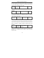
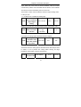
Note: The initial value of curling radius can be determined through two
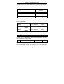
multi-function terminals. For example, select DI3,DI4 ports to determine
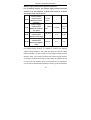
the value of initial curling radius. Set DI3 port parameter F4-02 to
27
Chapter 4 Parameter Description
32(select terminal 1 as initial curling radius) and DI4 port parameter to
33(select terminal 2 as initial curling radius). The selection of initial
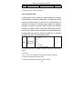
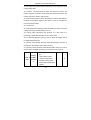
curling radius is as follows:
Initial curling radius
DI4
DI3
0
0
Determined by FH-12
0
1
Determined by FH-14
1
0
Determined by FH-15
1
1
Determined by FH-16
source
When the initial curling radius does not count from the hollow curling
radius, use the function. The initial curling radius is FH-12 by default, i.e.
hollow curling radius.
FH-14
FH-15
FH-16
initial curling
radius 1
initial curling
radius 2
initial curling
radius 3
1mm~10000mm
100mm
1mm~10000mm
100mm
1mm~10000mm
100mm
Set three different initial curling radii, and confirm them through
multi-function terminal.
FH-17
curling radius filtering time
0.0s~100.0s
1.0s
Lengthen curling radius filtering time to avoid fast change of curling
radius calculation (or input) result.
FH-18 current value of curling radius 1mm~10000mm
―――
Real-time display of current curling radiusIt is able to know the current
actual curling radius through the parameter .Also set the start curling
28
Chapter 4 Parameter Description
radius by modifying the parameter.
Relevant parameters for curling radius calculation with thickness
accumulation
Only when setting curling radius source FH-10 to 1, that is,
obtaining through thickness accumulation calculation, it is related
to the parameter.
FH-19
Number of pulses each turn
1~60000
1
It represents pulse number generated by turn counting signal when
winding shaft turns a round.
FH-20
Number of turns each layer 1~10000
1
It shows the rounds of winding shaft turning after the material wraps
one layer. It is used for wire.
0: FH-22 setting
FH-21
Material thickness 1: AI1 setting
setting source
2: AI2 setting
0
3: AI3 setting
Set the source of material thickness.
0: Set the material thickness with number in FH-12~FH-25.
1: AI1, 2: AI2, 3: AI3 Confirm the material thickness through input
channel set by analog value.
FH-22
Material thickness 0
0.01mm~100.00mm
0.01mm
FH-23
Material thickness 1
0.01mm~100.00mm
0.01mm
FH-24
Material thickness 2
0.01mm~100.00mm
0.01mm
Material thickness 3
0.01mm~100.00mm
0.01mm
FH-25
Set the material thickness with number, and select the terminal code
and thickness setting through material thickness.
29
Chapter 4 Parameter Description
FH-26 maximum thickness 0.01mm~100.00mm
1.00mm
When the material thickness is analog input, the maximum analog input
corresponds to the maximum thickness.
4.4 Line speed input
If curling radius source selects line speed calculation or tension
control mode as close-loop speed mode, it is required to obtain
correct line speed signal. In general, the convenient way for
obtaining line speed is through analog output of operation
frequency of traction (constant speed) inverter. The operation
frequency of traction inverter corresponds with the line speed in
linear. It only needs to set the maximum line speed (FH-28) to the
corresponding line speed of maximum frequency of operation
frequency of traction (constant speed) inverter.
0: No input
1: AI1
FH-27
line speed
2: AI2
0
input source 3: AI3
4: pulse input
5: communication setting
Line speed input source: Used as the way or channel for obtaining line
speed.
0: No input
1: AI1, 2: AI2, 3: AI3: Obtain line speed through analog input port.
4: Obtain line speed through pulse input.
5: Obtain line speed through communication method.
30
Chapter 4 Parameter Description
FH-28
maximum
line speed
0.1
m/Min~6500.0m
0.1m/Min
1000.0m/Min
/Min
When obtaining line speed through analog input, the maximum line
speed must be correctly set. The maximum value of analog input
corresponds with the value.
minimum line
FH-29
speed for curling
0.1
m/Min~6500
0.1m/Min
200.0m/Min
radius calculation m/Min
Set the minimum speed for starting calculation of curling radius. When
the inverter detects that the line speed is lower than the value, inverter
will stop curling radius calculation. Correct setting of the value will
effectively avoid great deviation of curling radius calculation when the
speed is reduced. In general, the value shall be set to over 20% of
maximum line speed.
FH-30
Actual line
speed
0.1 m/Min~6500.0m/Min
―――
The parameter will display actual line speed on line.
31
―――
Chapter 4 Parameter Description
4.5 Tension compensation
It is only relevant to the open loop torque mode.
When the tension control adopts open loop torque mode, during
the system acceleration/deceleration, additional torque shall be
provided to overcome the rotation inertia of the whole system.
Otherwise, too small tension upon wind-up acceleration and too
large tension upon deceleration, or too large tension upon
roll-down acceleration and too small tension upon deceleration
will be caused.
compensation
FH-31
coefficient self
learning torque
5.0%~80.0%
0.1%
20.0%
setting
It is used to set the torque used for inertia compensation self learning.
This function is reserved for the current version.
compens
FH-32
ation self
learning
action
0: no operation
1: Start to identify
automatically restore to
1
0 when the self learning
is ended.
Set the inertia compensation operation method:
0: no operation
1: Start to identify.
Press RUN key to start inertia identification.
Note: At this time, the inverter operates in panel control mode.
This function is reserved for the current version.
32
0
Chapter 4 Parameter Description
mechanical inertia
FH-33
1~10000
compensation
1
0
coefficient
It is used to compensate the rotation inertia of the system, including
inertia of the motor, rotation system, and the shaft. Such inertias are
fixed and independent of the curling radius. This parameter can be
obtained automatically by compensation coefficient self learning (this
function is reserved for the current version) or manually set. Upon
empty roll or small roll, if the material tension reduces during the
acceleration, increase the coefficient. Otherwise, the coefficient shall be
decreased.
FH-34
FH-35
material
density
0Kg/m^3~60000Kg/m^3
1Kg/m^3
0Kg/m^3
0mm~60000mm
1mm
0mm
material
width
The two parameters are relevant to the material inertia compensation.
The
inverter
will
automatically
calculate
the
material
inertia
compensation value according to the parameter and the curling radius.
friction
FH-36
compensation
0.0%~50.0%
0.1%
0.0%
coefficient
Take wind-up as an example. Because of the frictional resistance, the
material tension reduces, which is more obvious upon small roll, and
the tension will be nonlinear. This situation can be improved by setting
the parameter.
33
Chapter 4 Parameter Description
Material supply interrupt auto detection parameters
It is an auxiliary function. The material supply interrupt cannot be
detected in all the situations. If good result cannot be achieved
after proper effort, set FH-37 to 0.
material supply
FH-37
interrupt auto
detection function
0: inactive
1: active
1
0
selection
material supply
FH-38
interrupt auto
detection minimum
0.1~10000.0
m/Min
0.1m/Min
200.0m/
Min
line speed
material supply
FH-39
interrupt auto
detection error range
0.1%~50.0
%
0.1%
10.0%
0.1s
2.0s
material supply
FH-40
interrupt auto
detection judgment
0.1~60.0s
delay
This group of parameters is used for the inverter to automatically detect
the material supply interrupt. It is difficult to conduct auto material
supply interrupt detection. Only when line speed is used for curling
radius calculation can the inverter have the material supply interrupt
detection basis. The inverter will detect the material supply interrupt
according to the abnormal change of curling radius. By adjusting FH-38,
FH-39 and FH-40, mistaken report can be prevented, and adjustment
can be made for the detection sensitivity to achieve good result. ERR24
34
Chapter 4 Parameter Description
failure will be reported by the inverter after material supply interrupt is
detected.
FH-37: When it is set as 0, the material supply interrupt auto detection
function is inactive.
FH-38: Only when the line speed is higher than the value can the
material supply interrupt be detected.
FH-39: Only when the abnormal change of the curling radius exceeds
this range can the material supply interrupt be detected.
FH-40: Only when the lasting time of the abnormal change of the
curling radius exceeds this delay can the material supply interrupt be
detected.
When the above three conditions are satisfied simultaneously, the
inverter reports ERR24 (material supply interrupt failure)
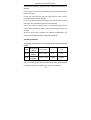
4.6 PID parameters
This group of parameters is only related to the close loop speed
mode.
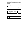
FH-41
FH-42
FH-43
proportiona
l gain 2
integral
time I2
differential
time D2
0.0s~100.0s
0.1
20.0
0.01s~10.00s
0.01s
2.00s
0.000s~1.000s
0.001s
0.000s
This is the second group of parameters. FA-05, FA-06 and FA-07
belong to the first group of PID parameters. Best result can be achieved
in different conditions by setting the two groups of parameters.
35
Chapter 4 Parameter Description
0: Only the first
group of PID
parameters are
auto
FH-44
adjustment
basis for PID
parameters
used
1: Adjust according
to the curling radius
1
0
2: Adjust according
to the operating
frequency
3: Adjust according
to the line speed
Select auto adjustment basis for PID parameters.
0: Only the first group of PID parameters is used, and the second group
is inactive.
1: Adjust according to the curling radius. The first group of PID
parameters is used for empty roll, while the second group of PID
parameters is used for full roll. The PID parameters change
continuously during the process.
2.
Adjust according to the operating frequency: this first group of PID
parameters is used upon zero speed, while the second group of
parameters is used upon maximum frequency. The PID parameters
change continuously during the process.
3.
Adjust according to the line speed: this first group of PID
parameters is used upon zero speed, while the second group of
parameters is used upon maximum line speed. The PID parameters
36
Chapter 4 Parameter Description
change continuously during the process.
37
Chapter 4 Parameter Description
4.7 Auto roll alternation parameter
FH-45
pre-drive
-50.0%~+50.0%
speed gain
0.1%
0.0%
When conducting roll alternation during the operation, to avoid causing
too large shock, it is necessary to rotate the wind-up roll (roll-down roll)
in advance, and the rotating line speed shall be consistent with the line
speed of the materials in operation. This is the pre-drive function.
When the pre-drive terminal is active, the inverter will automatically
calculate the output frequency according to the measured line speed
and curling radius, so as to match the line speed.
This parameter can adjust the line speed matching relation. When it is
set as a negative value, the surface speed of the pre-drive roll will be
lower than the line speed of the material in operation.
Upon pre-drive, it is necessary to pause the curling radius calculation
(use the curling radius calculation stop terminal) or set the function
code FH-55 to 1.
0: F2-09 setting
FH-46
pre-drive torque 1: Set the limit
limit selection
according to tension
1
0
setting
It is used to select the torque limit setting mode upon pre-drive. When it
is set as 1, the output torque can be limited according to the tension
setting and the current curling radius. It is used together with FH-47.
38
Chapter 4 Parameter Description
FH-47
pre-drive
-50.0%~+50.0%
torque gain
0.1%
0.0%
When FH-46 is set as 1, this parameter can be used to adjust the
torque limit upon pre-drive, and to get large or small tension according
to the system control demand.
4.8 Additional parameters
This section describes the additional parameters for the auxiliary
control part according to the actual use demand. The parameters
in this section are quite dispersing.
tension
FH-48 taper source
selection
0: FH-09 setting
1: AI1 setting
2: AI2 setting
1
0
3: AI3 setting
Select the setting mode of the tension taper. When analog setting is
selected, the settable range is 0%~100%.
tension close loop
FH-49
control adjustment
0.0%~100.0%
0.1%
50.0%
limit
Set the PID regulator output limit in tension close loop control mode.
The limit is corresponding to the speed of the whole system.
tension close loop
FH-50
control adjustment
0.0%~100.0%
0.1%
0.0%
limit offset
Set the offset of the PID regulator output limit in tension close loop
39
Chapter 4 Parameter Description
control mode. If the value is 0, when the system is at zero speed, the
regulator will be inactive. Proper offset value shall be set to avoid this
problem.
high-speed
FH-51
torque
compensation
-50.0%~+50.0%
0.1%
0.0%
coefficient
It is useful for tension open loop control (torque mode)Some system
has different resisting forces at high speed and at low speed. It is
impossible to achieve constant tension for the whole process with the
constant friction compensation torque only. The influence of the system
can be compensated by properly setting this parameter. This parameter
is presented as the percentage of the rated torque.
FH-52
compensation 0: frequency
basis
1: line speed
1
0
It is used together with FH-51 to select the basis of high-speed torque
compensation.
external taper 0: FH-54 setting
control
FH-53
maximum
1: AI1 setting
2: AI2 setting
1
0
output setting 3: AI3 setting
source
This function brings much convenience to the user. The AO output of
the inverter can be set as the external taper output, and the inverter can
adjust the external taper output according to the current tension
proportion to control the external execution parts, such as the control
proportion valve, so as to realize the purpose of controlling the tension
40
Chapter 4 Parameter Description
taper. When the roll is used as tension feedback, what the inverter
controls is the position of the roll rather than the tension of the material.
The tension control is decided by the force of the roll.
This function code is used to select the maximum output setting mode.
0: set by FH-54
1, 2, 3: select to be controlled by analog input
external taper
FH-54
control maximum
output digital
0.0%~100.0%
0.1%
100.0%
setting
When FH-54 is set as 0, the initial output is set by the function code.
pre-drive curling
FH-55 radius calculation
selection
0: calculate
1
1: stop
0
calculation
Select whether the curling radius calculation is stopped upon pre-drive.
In general, the curling radius calculation shall be stopped.
curling radius
FH-56
calculation stop
delay after ending
0.0s~10.0s
0.1s
5.0s
of pre-drive
If curling radius calculation is stopped upon pre-drive, this function code
will decide when the curling radius calculation starts after the pre-drive
is ended, so as to prevent the curling radius causing too large
fluctuation at the instant of the pre-drive ending.
FH-57
tension
increase ratio
0.0%~200.0%
41
0.1%
50.0%
Chapter 4 Parameter Description
When the tension increase terminal is active, the tension controlled by
the inverter will be increased according to the parameter.
line
FH-58
speed
setting
source
0: AI1 setting
1: AI2 setting
1
2: AI3 setting
0
3: pulse setting
4: communication setting
It is relevant to the situation when FH-00 is set as 4 (line speed control
mode). For details, please refer to the description of FH-00.
FH-59
taper compensation
1mm~10000mm
correction
1mm
0
It is the auxiliary parameter for tension taper control. For details, please
refer to the description of FH-09.
tension taper
effectiveness
FH-60
selection for
close loop
0: taper effective
1: taper ineffective
1
0
tension control
This function code decides whether the tension taper will be effective
upon close loop tension control.
In general, when the control adopts roll feedback, it is unnecessary for
the tension taper to have influence over the roll setting position (PID
reference). However, it will be effective on the external taper output
because it is used for the control proportion valve to adjust the tension.
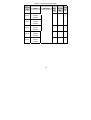
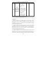
Input/output selection: when the inverter is the tension control
inverter, the following functions are the supplementary for the
42
Chapter 4 Parameter Description
functions of the multi-function terminals of the MD320 inverter.
F4-00
F4-01
F4-02
F4-03
F4-04
F4-05
F4-06
F4-07
F4-08
DI1 terminal
31: curling radius
function selection reset
32: initial curling
DI2 terminal
function selection radius selection
terminal 1
DI3 terminal
function selection 33: initial curling
radius selection
DI4 terminal
function selection terminal 2
34: Pre-drive
DI5 terminal
function selection command terminal
35: turn counting
DI6 terminal
function selection signal
36: Torque memory
DI7 terminal
function selection 37: torque memory
enable
DI8 terminal
38: wind-up
function selection
roll-down switching
DI9 terminal
39: curling radius
function selection
calculation stop
40: thickness
selection terminal 1
41: thickness
F4-09
DI10 terminal
selection terminal 2
function selection 42: tension control
disable terminal
43: tension
increase terminal
31: curling radius rest
when replacing with a new roll, the curling
radius shall be reset to initial curling radius.
43
Chapter 4 Parameter Description
32, 33: Initial curling radius selection terminal, used to select the initial
curling radius value.
34: Pre-drive command terminal. When the terminal is active, the
inverter operates in pre-drive mode. When the terminal is inactive, the
inverter operates in tension control mode.
35: Turn calculation signal. When calculating the curling radius with the
thickness accumulation method, this signal is used to calculate the
turns of the shaft rotation.
36, 37: reserved.
38: wind-up/roll-down switching. When the terminal is active, the actual
curling mode is the inverted setting of FH-01.
39: Curling radius calculation stop terminal. It is used when it is
necessary to pause the calculation of the curling radius.
40, 41: thickness selection terminal, used to select the setting source
for digital setting thickness.
42: Tension control disable terminal. When this terminal is active, it is
equivalent to the situation that FH-00 is set as 0.
43: Tension increase terminal. When this terminal is active, the control
tension will be increased according to the proportion set in FH-57.
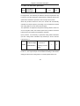
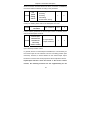
12: external taper control
analog
F5-07~F
output
5-09
selectio
n
output
13: curling radius output:
0%~100% corresponds to
0~maximum curling radius
14: actual tension (after taper
calculation)
44
1
0
Warranty Agreement
1.
The warranty period of the product is 18 months (refer to the
barcode on the equipment body). During the warranty period, if
the product fails or is damaged under the condition of normal use
by following the instruction, Our company will be responsible for
free maintenance.
2.
Within the warranty period, maintenance will be charged for the
damages caused by the following reasons:
A.
The damage caused by improper use or repair/modification
B.
The damage caused by fire, flood, abnormal voltage, other
without prior permission;
disasters and second disaster;
C.
The damage caused by dropping or transportation after the
purchase.
D.
The damage caused by the improper operation;
E.
The damage or failure caused by the trouble out of the
equipment (e.g. external device)
3.
If there is any failure or damage to the product, please correctly
fill out the Product Warranty Card in detail.
4.
The maintenance fee is charged according to the newly adjusted
Maintenance Price List by our company.
5.
In general, the warranty card will not be re-issued. Please keep
the card and present it to the maintenance personnel when
asking for maintenance.
6.
If there is any problem during the service, please contact the
agent of our company or our company directly.
7.
This agreement shall be interpreted by Shenzhen Invoance
Technology Co., Ltd.
Shenzhen Invoance Technology Co., Ltd.
Service Department
Address: Block E, Hongwei Industry Park, Liuxian Road,
Baocheng No. 70 Zone, Bao’an District, Shenzhen
Tel.: 0755-29619910
Postal code: 518101
Product Warranty Card
Add. of unit:
Customer
Name of unit:
Contact person:
P.C.:
Tel.:
information
Product model:
Product
Body barcode (Attach here):
information
Name of agent:
(Maintenance time and content):
Failure
information
Maintenance
personnel: