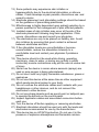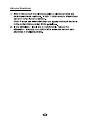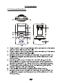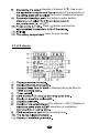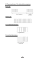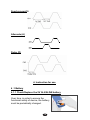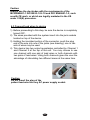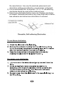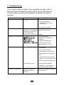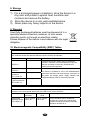
1
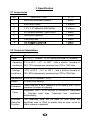
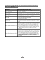
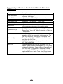
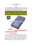
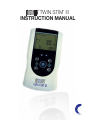
TWIN STIM III
INSTRUCTION MANUAL
®
TM
This manual is valid for the InTENSity Twin Stim III
TENS/EMS Combo Stimulator
This user manual is published by Current Solutions™, LLC
Current Solutions™, LLC does not guarantee its contents and
reserves the right to improve and amend it at any time without
prior notice. Amendments may however be published in new
editions of this manual.
All Rights Reserved.Rev.V1.1 © 2010
United States Federal Law restricts this device to sale by
or on the order of a physician or licensed practitioner
:
Declaration of conformity:
Current Solutions™, LLC declares that the device complies
with following normative documents:
IEC60601-1, IEC60601-1-2, I EC60601-2-10, IEC60601-1-4,
ISO10993-5, ISO10993-10, ISO10993-1
Table of Contents
1. SAFETY INFORMATION………………………………………………………………….... 4
1.1 General description
1.2 Medical background
1.3 Indication for use
1.4 Contraindications
1.5 Warnings, Cautions, Adverse Reactions
2. PRESENTATION………………………………………………………………..………………... 12
2.1 Front and Rear panel
2.2 LCD display
3. SPECIFICATION……………………………………………………………..………………….... 15
3.1 Accessories
3.2 Technical information
3.3 The waveforms of the stimulation programs
4. INSTRUCTIONS FOR USE ………………………………..………………………......... 19
4.1 Battery
4.2 Connect electrodes to lead wires
4.3 Connect lead wires to device
4.4 Electrodes
4.5 Turn ON
4.6 Select the Therapeutic Mode
4.7 Steps to set a new program
4.8 Adjust Channel Intensity
4.9 Safty lock feature
4.10 Stop the treatment
4.11 Turn OFF
4.12 Low battery indicator
5. PROGRAM...........................................................................................................................… 28
6. CLEANING AND CARE…………………………………………………….……………….. 29
6.1
6.2
6.3
6.4
6.5
Tips for skin care
Cleaning the device
Electrodes
Cleaning the Electrode cords
Maintenance
7. TROUBLESHOOTING …………………………………………………………………….... 32
8. STORAGE……………………………………………………………………………………............. 33
9. DISPOSAL…………………………………………………………………………………................ 33
…… 33
10. ELECTROMAGNETIC COMPATIBITY (EMC) TABLES
11. GLOSSARY OF SYMBOLS
12. WARRANTY
35
46
3
1.Safety information
1.1 General
InTENSity Twin Stim III is a portable electrotherapy device featuring
TM
two therapeutic modes: Transcutaneous Electrical Nerve Stimulator
(TENS) and Electrical Muscle Stimulation (EMS), which are used
for pain relief and electrical muscle stimulation. The stimulator
sends gentle electrical current to underlying nerves and muscle
group via electrodes applied on the skin. The parameters of device
are controlled by the buttons on the front panel. The intensity level
is adjustable according to the needs of patients.
1.2 Medical background
EXPLANATION OF PAIN
Pain is a warning system and the body’s method of telling us that
something is wrong. Pain is important; without it abnormal conditions
may go undetected, causing damage or injury to vital parts of our
bodies. Even though pain is a necessary warning signal of trauma or
malfunction in the body, nature may have gone too far in its design.
Aside from its value in diagnosis, long-lasting persistent pain serves
no useful purpose. Pain does not begin until the coded message
travels to the brain where it is decoded, analyzed, and then reacted to.
The pain message travels from the injured area along the small
nerves leading to the spinal cord. Here the message is switched to
different nerves that travel up the spinal cord to the brain. The pain
message is then interpreted, referred back and the pain is felt.
EXPLANATION OF TENS
Transcutaneous Electrical Nerve Stimulation (TENS) is a noninvasive, drug free method of controlling pain. TENS uses tiny
electrical impulses sent through the skin to nerves to modify your
pain perception. TENS does not cure any physiological problem;
it only helps control the pain. TENS does not work for everyone;
4
however, in most patients it is effective in reducing or eliminating
the pain, allowing for a return to normal activity.
HOW TENS WORKS
There is nothing “magic” about Transcutaneous Electrical Nerve
Stimulation (TENS). TENS is intended to be used to relieve pain.
The TENS unit sends comfortable impulses through the skin that
stimulate the nerve (or nerves) in the treatment area. In many
cases, this stimulation will greatly reduce or eliminate the pain
sensation the patient feels. Pain relief varies by individual patient,
mode selected for therapy, and the type of pain. In many patients,
the reduction or elimination of pain lasts longer than the actual
period of stimulation (sometimes as much as three to four times
longer). In others, pain is only modified while stimulation actually
occurs. You may discuss this with your physician or therapist.
EXPLANATION OF EMS
Electrical Muscle Stimulation (EMS) is an internationally accepted
and proven way of treating muscular injuries. It works by sending
electronic pulses to the muscle needing treatment; this causes the
muscle to exercise passively. It is a product derived from the
square waveform, originally invented by John Faraday in 1831.
Through the square wave pattern it is able to work directly on
muscle motor neurons. This device has low frequency and this in
conjunction with the square wave pattern allows direct work on
muscle groupings. This is being widely used in hospitals and
sports clinics for the treatment of muscular injuries and for the reeducation of paralyzed muscles, to prevent atrophy in affected
muscles and improving muscle tone and blood circulation.
HOW EMS WORKS
The EMS units send comfortable impulses through the skin that
stimulate the nerves in the treatment area. When the muscle
receives this signal it contracts as if the brain has sent the signal
itself. As the signal strength increases, the muscle flexes as in
5
physical exercise. Then when the pulse ceases, the muscle
relaxes and the cycle is repeated. The goal of electrical muscle
stimulation is to achieve contractions or vibrations in the muscles.
Normal muscular activity is controlled by the central and
peripheral nervous systems, which transmit electrical signals to
the muscles. EMS works similarly but uses an external source
(the stimulator)with electrodes attached to the skin for transmitting
electrical impulses into the body. The impulses stimulate the
nerves to send signals to a specifically targeted muscle, which
reacts by contracting, just as it does with normal muscular activity.
1.3 Indication for use
InTENSity
TM
Twin Stim III Stimulator may be used for
For Transcutaneous Electrical Nerve Stimulator therapeutic
modes (TENS):
1) Symptomatic relief of chronic intractable pain.
2) Post traumatic pain.
3) Post surgical pain.
For Electrical Muscle Stimulation / Neuromuscular Stimulation
therapeutic mode (EMS):
1) Relaxation of muscle spasm.
2) Increase of blood flow circulation.
3) Prevention of disuse atrophy.
4) Muscle re-education.
5) Maintaining or increasing range of motion.
imulation of lower leg muscles to
prevent venous thrombosis.
IMPORTANT SAFETY INFORMATION!
Read the instruction manual before operation. Be sure to comply
with all “Contraindications”,“Warnings”, “Cautions” and “Adverse
reactions” in the manual. Failure to follow instructions can cause
harm to user or device.
1.4 Contraindications
1.5 Warnings, Cautions and Adverse Reactions
7
8
out of reach of children.
you are in any doubt whatsoever.
CAUTIONS:
13) Some patients may experience skin irritation or
hypersensitivity due to the electrical stimulation or silicone
rubber. If rash develops or pain persists, discontinue use and
consult a doctor.
14) Electrode placement and stimulation settings should be based
on the guidance of prescribing practitioner.
15) Effectiveness is highly dependent upon patient selection by a
person qualified in the management of pain afflicted patients.
16) Isolated cases of skin irritation may occur at the site of the
electrode placement following long-term application. If this
occurs, discontinue use and consult your physician.
17) The electrodes are only to be placed on healthy skin. Avoid
skin irritation by ensuring that good contact is achieved
between electrodes and skin.
18) If the stimulation levels are uncomfortable or become
uncomfortable, reduce the stimulation Intensity to a
comfortable level and contact your physician if problems
persist.
19) This device should not be used while driving, operating
machinery, close to water, or during any activity in which
involuntary muscle contractions may put the user at undue risk
of injury.
20) Never use the device in rooms where aerosols (sprays) are
used or pure oxygen is being administered.
21) Do not use it near any highly flammable substances, gases or
explosives.
22) Do not use this device at the same time as other equipment
which sends electrical pulses to your body.
23) Do not confuse the electrode cables and contacts with your
headphones or other devices, and do not connect the
electrodes to other devices.
24) Do not use sharp objects such as pencil point or ballpoint pen
to operate the buttons on the control panel.
25) Inspect Applicator cables and associated connectors before
each use.
26) Turn the device off before applying or removing electrodes.
27) Electrical stimulators should be used only with the leads and
electrodes recommended for use by the manufacturer.
28) This device has no AP/APG protection. Do not use it in the
presence of explosive atmosphere and flammable mixture.
Adverse Reactions:
2. Presentation
2.1 Front and Rear Panel
12
intensity of channel 2 [▼]. Use to set
rameter of the waveform in
the current treatment program.
ss the button to enter setting
▲] and [▼].
Press [ ] button and hold for
cover for user access.
2.2 LCD display
or Displays the cycle time for
y for channel 1 (CH1); Display of
S waveform of contraction
raction (working) time
13
12) Display of the output intensity for channel 2 (CH2); Display
of waveform pulse rate or EMS waveform of relaxation time
in setting state.
13) Displays channel 2.
14) EMS waveform of relaxation time.
15) Displays the treatment time or EMS waveform of ramp up and
ramp down time.
16) Low-battery indicator.
3. Specification
3.1 Accessories
No
1
DESCRIPTION
Electrical stimulator device
Q’TY
1 piece
2
Electrode Leads
2 pieces
3
1.5”x 1.5” Adhesive Electrodes
4 pieces
4
9V Alkaline Battery, type 6LR61
1 piece
5
Instruction Manual
1 piece
6
Carrying case
1 piece
3.2 Technical information
Channel
Power
l
Operating
conditions
Dual, isolated between channels
9.0 V DC-1 Alkaline *6LR61 battery(optional AC Adaptor)
Storage
conditions
-10°C to 50°C (14℉ to 122℉)with a relative humidity of
10%-90%,atmospheric pressure from 700 to 1060 Hpa
5°C to 40°C (41℉ to 104℉)with a relative humidity of
30%-75%,atmospheric pressure from 700 to 1060 Hpa
Dimensions 4.5×2.55×0.9 inches(L*W*H)
Weight
0.28 lbs(With battery)
Tolerance
There may be a ±5% tolerance of all setting and ±10%
tolerance of output of intensity.
Timer
Electrode
Detection
Function
Adjustable, from 1 to 60 minutes or continuous, Adjustable
in 1minutes each step. Treatment time countdown
automatically.
The amplitude level will be reset to 0mA when the
amplitude level is 12mA or greater and an open circuit at
either channel is detected.
Technical specifications for Transcutaneous Electrical Nerve
Stimulator (TENS) mode
Waveform
Pulse amplitude
Mono-phase square pulse wave
Adjustable, 0~105mA peak at 1000 ohm Load each
channel, 1mA/Step.
Pulse Width
Adjustable, from 50 to 300us microseconds, 10μS/step
Pulse Rate
Adjustable, from 1 to 150 Hz, 1 Hz/step
Burst (B)
Normal (N)
Pulse Width Modulation (M)
Pulse Rate Modulation (M1)
Burst rate: Adjustable, 0.5 ~ 5Hz
Pulse width adjustable,50-300uS
Frequency fixed=10Hz
The pulse rate and pulse width are adjustable. It
generates continuous stimulation based on the setting
value.
The pulse width is automatically varied in a cycle time.
The pulse width is decreased from its original setting to
60% in setting cycle time, and then increased from
60% to its original setting in nest setting cycle time. In
this program, pulse rate (1 to 150Hz), pulse width (50
to 300us) and cycle time (5 to 30 sec) are fully
adjustable.
The pulse rate is automatically varied in a cycle time.
The pulse rate is decreased from its original setting to
60% in setting cycle time, and then increased from
60% to its original setting in nest setting cycle time. In
this program, pulse rate (1 to 150Hz), pulse width (50
to 300us) and cycle time (5 to 30 sec) are fully
adjustable.
Technical specifications for Electrical Muscle Stimulation
(EMS) mode
Waveform:
Pulse amplitude
Pulse Width
Pulse Rate
Contraction time
Relaxation (OFF) time
Ramp time
Synchronous (S)
Alternate (A)
Delay (D)
Mono-phase square pulse wave
Adjustable, 0~105mA peak at 1000 ohm Load each
channel, 1mA/Step.
Adjustable, from 50 to 300μS microseconds,
Adjustable, from 1 to 150 Hz, 1 Hz/step
Adjustable, 1~60 seconds , 1 Sec./ step
Adjustable, 0~60 seconds , 1 Sec./ step
Adjustable, 1~6 seconds, 1 Sec. / step, The “On” time
will increase and decrease in the setting value.
Stimulation of both channels occurs synchronously.
The “ON” time including “Contraction”, “Ramp Up” and
“Ramp Down” time. ON TIME=Contraction + Ramp up
+ Ramp down
The Stimulation of the CH2 will occur after the 1st
operation of CH1 is completed. In this program, The
“ON” time including “Contraction”, “Ramp Up” and
“Ramp Down” time. The OFF Time should be equal or
more than the ON Time
ON TIME=Contraction + Ramp up + Ramp down
OFF TIME ≥ ON TIME
The Stimulation of the CH2 will occur after CH1 is
started + Delay Time. In this program, The “ON” time
includes “Contraction”, “Ramp Up” and “Ramp Down”
time. ON TIME = Contraction + Ramp up + Ramp
down time. The OFF Time should be equal or more
than the ON Time + Delay Time. Time Delay time is
adjustable from 1 to 10 seconds in this program.
3.3 The waveforms of the stimulation programs
Burst (B)
Normal (N)
Pulse Width Modulation
cycle time
Pulse Rate Modulation
Synchronous(S)
Alternate (A)
Delay (D)
4. Instruction for use
4 .1 Battery
4.1.1 Check/Replace the 9V ALKALINE battery
Over time, in order to ensure the
functional safety of device, the battery
must be periodically changed.
19
4.1.2 Disposal of battery
Spent batteries do not belong in household waste.
Dispose of the battery according to the current federal,
state and local regulations.
Caution:
1) Battery may be fatal if swallowed. Therefore, keep the
battery and the product out of the range of children, if a
battery was swallowed, consult a physician immediately.
2) If a battery has leaked, avoid contact with skin, eyes and
mucus membranes, Rinse the affected spots with lots of
clear water immediately and contact a physician right
away.
3) Battery may not be charged, dismantled, thrown into fire
or short-circuited.
4) Protect battery from excess heat; Take the battery out of
the product if they are spent or in case you no longer use
the article. This prevents damage caused by leaking battery.
5) Always replace the same type battery.
4.2 Connect electrodes to lead wires
Insert the lead wire connector into
electrode connector (standard 0.08 inch
female connection). Make sure there are
no bare metal pins exposed.
20
Caution:
Always use the electrodes with the requirements of the
IEC/EN60601-1 ISO10993-1/-5/-10 and IEC/ EN60601-1-2, such
as with CE mark, or which are legally marketed in the US
under 510(K) procedure.
4.3 Connect lead wires to device
1) Before proceeding to this step, be sure the device is completely
turned OFF.
2) The wires provided with the system insert into the jack sockets
located on top of the device.
3) Holding the insulated portion of the connector, push the plug
end of the wire into one of the jacks (see drawing); one or two
sets of wires may be used.
4) This device has two output receptacles controlled by Channel 1
and Channel 2 at the top of the unit. You may choose to use
one channel with one pair of lead wires or both channels with
two pairs of lead wires. Using both channels gives the user the
advantage of stimulating two different areas at the same time.
Caution:
Do not insert the plug of the
patient lead wire into any AC power supply socket.
21
4.4 Electrode
4.4.1 Electrode options
The electrodes are disposable and should be routinely replaced
when they start to lose their adhesive nature. If you are unsure
of your electrodes adhesive properties, order new replacement
electrodes. Replacement electrodes should be re-ordered
through or on the advice of your physician to ensure proper
quality. Follow application procedures outlined in electrode
packing, to maintain optimal stimulation and to prevent skin
irritation.
4.4.2 Place electrodes on skin
Apply electrodes to the exact site indicated by your physician or
therapist. Be sure the skin surface over which electrodes are
placed is thoroughly cleaned and dried. Make sure the electrodes
are placed firmly to the skin and make good contact between the
skin and the electrodes. Place the electrodes over the skin; attach
them properly, firmly, and evenly.
Caution:
1) Before applying the selfadhesive electrodes, it is
recommended to
wash and degrease the skin, and then dry it.
2) Do not turn on the device when the self-adhesive
electrodes are not positioned on the body.
3) Never remove the self-adhesive electrodes from the skin
while the device is still turned on.
4) It is recommended that, at minimum, 1.5” x 1.5” selfadhering electrodes are used at the treatment area
22
4.4.3 Electrode placement
The placement of electrodes can be one of the most important
parameters in achieving success with therapy. Of utmost
importance is the willingness of the physician to try the various
styles of electrode placement to find which method best fits the
needs of the individual patient.
Every patient responds to electrical stimulation differently and
their needs may vary from the conventional settings suggested
here. If the initial results are not positive, speak to your
physician about alternative stimulation settings and/or
electrode placements. Once an acceptable location has been
achieved, mark down the electrode sites and the device
settings, so the patient can easily continue treatment.
4.5 Turn on
Before using the device for the first time, you are strongly advised
to take careful note of the contraindications and safety measures
detailed at the beginning of this manual (Safety information), as
this powerful equipment is neither a toy nor a gadget! In order to
turn on the device, PRESS and RELEASE the [ ] button.The
operation page appears on the
screen.
4.6 Select the Therapeutic Mode
There are 2 therapeutic modes
available –TENS and EMS. The
therapeutic mode can be selected
by pressing the [M] control.
Caution:
Consult your physician for your suitable therapeutic mode
4.7 Steps to Set a New Program
4.7.1 TENS Setting
Press the [S] button cycle to enter the setting state. The settings
can be adjusted according to the following steps:
1) Set the Therapeutic Program
There are 4 programs in TENS therapeutic
mode available –Burst (B), Normal (N), Pulse
Width Modulation (M), and Pulse Rate
Modulation (M1). The therapeutic program can
be selected by pressing the [▲] and [▼]
button. When you choose to “B” program,
program [B] outside of the box will be flashing.
2) Set Cycle Time (Optional)
Cycle time is adjustable from 5 to 30 seconds. Only modulation
has this parameter setting. Press [S] button cycle to enter this menu,
and then press the [▲] and [▼] button to adjusting the setting.
3) Set Timer
Press [S] button cycle to enter this setting. The treatment time is
adjustable from 1 to 60 minutes or Continuous. Press [▲] or [▼]
button control to adjust setting. You can set the timer to
“Continuous” mode by pressing the [▲] control when it shows 60
minutes. The output will be shut off when time is up.
4) Set Pulse Width
Pulse Width is adjustable from 50 uS to 300 uS. Press [S] button to
enter this menu, then press [▲] or [▼]button to adjust the setting.
24
5) Set Pulse Rate
Pulse rate is adjustable from 1 Hz to 150 Hz (0, 5 Hz to 5 Hz for
Burst). Press [S] button cycle to enter this menu, and then press
[▲] or [▼]button to adjust the setting.
4.7.2 EMS Setting
Press the [S] button cycle to enter the setting
state. The settings can be adjusted
according to the following steps:
1) Set the Therapeutic Program
There are 3 programs in EMS therapeutic
mode available –Synchronous, Alternate and Delay,. The
therapeutic program can be selected by pressing the [▲] and
[▼]button. When you choose to [S] program, program [S] outside of
the box will be flashing.
2) Set Timer
Press [S] button cycle to enter this setting. The treatment time is
adjustable from 1 to 60 minutes or Continuous. Press [▲] or [▼]
control to adjust setting. You can set the timer to “Continuous” mode
by pressing the [▲] button when it shows 60 minutes. The output
will be shut off when time is up.
3) Set Pulse Width
The pulse width determines the length of time. Each electrical
signal is applied through the skin, which controls the strength and
sensation of the stimulation. Press [S] button cycle to enter this
setting. The pulse width is adjustable from 50 to 300 uS.
Press [▲] or [▼]button to adjust the setting.
4) Set Pulse Rate
The pulse rate determines how many electrical impulses are
applied through the skin each second. Press [S] button cycle to
enter this menu. By pressing the [▲] or [▼]button to adjusting the
setting. The pulse rate is adjustable from 1 Hz to 150 Hz.
5) Set Delay Time (Optional)
Delay time is adjustable from 1 to 10 seconds.
25
Only Delay therapeutic program has this parameter setting. Press [S]
button cycle to enter this menu, and then press the [▲] and [▼]
button to adjusting the setting.
6) Set Ramp Time
The ramp time controls the time of output current that increase from
0 to the
7) Set Contract Time
The contract Time controls the time of stimulation. The contraction
time can be adjusted. Press [S] button cycle to enter this menu, and
then press the [▲] and [▼] button to adjusting the setting. Both
channels’ stimulation is cycled on and off by the contraction and
relaxation settings. The range is adjustable from 1 to 60 seconds.
Caution:
Contract time does not include the ramp up and ramp down
time; ON time=Ramp up + Contract time + Ramp down.
8) Set Relaxation (OFF) time
The Off Time controls the time of relaxation. The relaxation time can
be adjusted. Press [S] button cycle to enter this menu, and then
press the [▲] and [▼] button to adjusting the setting. Both channels'
stimulation is cycled on and off by the contraction and relaxation
settings. The range is adjustable from 0 to 60 seconds.
In Alternate program, the OFF Time should be equal or more than
the ON Time. (OFF TIME ≥ON TIME)
4.8 Adjust Channel Intensity
Press the intensity control button ([▲] and [▼]) to control the
intensity output. Slowly press the intensity button control until you
reach the setting recommended by your physician or therapist.
Repeat for the other channel, if both channels are to be used.
Caution:
1) If the stimulation levels are uncomfortable or become
uncomfortable, reduce the stimulation intensity to a
comfortable level and contact your medical practitioner if
problems persist.
2) If the electrodes are not placed firmly on the skin or the
device is not connected to the electrodes, and the
stimulator’s output intensity surpasses 12mA, the amplitude
level will be reset to 0 mA automatically.
4.9. Safety Lock Feature
The Safety Lock Feature automatically activates after there is no
operation in the panel for 30 seconds by locking out the ability to
press the buttons.This is a safety feature to prevent accidental
changes to your settings and to prevent accidental increases to the
intensity levels.You can press either one of the
button to unlock
the device.
4.10. Stop the treatment
When you have activated the treatment timer, you can press the [M]
button or the [ ] button to control or stop the treatment.
Caution:
Default state, if the button is locked, you can press only one
of the [ ] buttons to unlock, and then press the [M] button or
the [ ] button to control stop the treatment.
4.11. Turn OFF
PRESS [ ] button and HOLD for approximately 3 seconds to
turn OFF the device.
Caution:
1)
2)
If there is no operation in the panel for 2 minutes in the
waiting state, the device will be turned off automatically.
In shutdown state, keep pressing the channel 2[ ]first, and
then press [ ]button at the same to restore factory
parameter settings
27
4.12. Low battery indicator
When the low power indicator flashes, the device will be turned off
automatically, the battery should be replaced with a new one as
soon as possible. However, the unit may continue to operate for an
extended period depending on the setting intensity level.
5. Program
Mode
TENS
EMS
Program
Modulation
Method
Frequency
Pulse
Width
Treatment time
B
Burst
0.5-5Hz
50-300us
1-60min,continuous
N
Continuous
1-150Hz
50-300us
1-60min,continuous
M
Pulse width
modulation
1-150Hz
50-300us
1-60min,continuous
M1
Frequency
modulation
1-150Hz
50-300us
1-60min,continuous
S
Synchronous
mode
1-150Hz
50-300us
1-60min,continuous
A
Asynchronous
mode
1-150Hz
50-300us
1-60min,continuous
D
Delay mode
1-150Hz
50-300us
1-60min,continuous
28
6. Cleaning and Care
6.1 Tips for skin care
To avoid skin irritation, especially if you have sensitive skin, follow
these suggestions:
ou will be placing the electrodes,
using mild soap and water before applying electrodes, and
after taking them off. Be sure to rinse soap off thoroughly and
dry skin well.
2) Excess hair may be clipped with scissors; do not shave
stimulation area.
3) Wipe the area with the skin preparation your clinician has
recommended. Let this dry. Apply electrodes as directed.
4) Many skin problems arise from the “pulling stress” from
adhesive patches that are excessively stretched across the
skin during application. To prevent this, apply electrodes from
center outward; avoid stretching over the skin.
5) To minimize “pulling stress”, tape extra lengths of lead wires
to the skin in a loop to prevent tugging on electrodes.
6) When removing electrodes, always remove by pulling in the
direction of hair growth.
6.2 Cleaning the device
1) Remove the battery from the device every time when you clean.
2) Clean the device after use with a soft, slight moistened cloth.
In case of more extreme soiling you can also moisten the cloth
with mild soapy water.
3) Do not use any chemical cleaners or abrasive agents for
cleaning.
6.3 Electrodes
1) Use the device only with the leads and electrodes provided by
the manufacturer. Use only the electrode placements and
stimulation settings prescribed by your physician or therapist.
2) It is recommended that, at minimum, 1.5” x 1.5” self-adhering
electrodes should be used at the treatment area.
3) Inspect your electrodes before every use. Replace electrodes
as needed. Reusable electrodes may cause slight skin irritation,
lose adhesion and deliver less stimulation if overused.
To use these electrodes:
To remove your electrodes:
Caution:
1) Do not pull on the electrode wire. Doing so may damage
the wire and electrode.
2) Do not apply to broken skin.
3) The electrodes should be discarded when they are no
longer adhering.
4) The electrodes are intended for single patient use only.
5) If irritation occurs, discontinue use and consult your
clinician.
6) Read the instructions for use of self-adhesive electrodes
before application.
7) Always use the electrodes with the requirements of the
IEC/EN60601-1, ISO10993-1/-5/-10 and IEC/ EN60601-1-2,
such as with CE mark, or are legally marketed in the US
under 510(K) procedure.
6.4 Cleaning the Electrode's cords
Clean the electrode cords by wiping them with a damp cloth.
Coating them lightly with talcum powder will reduce tangles and
prolong the life.
6.5 Maintenance
31
7. Troubleshooting
If your device does not seem to be operating correctly, refer to
the chart below to determine what may be wrong. Should none
of these measures correct the problem, the device should be
serviced.
Problem
Display fails to light up
Possible Cause
Battery contact failure
Solution
1. Try fresh batteries.
2. Ensure batteries are
inserted correctly. Check
the following:
• All contacts are in place
Stimulation weak
Electrodes or Lead Wires
1. Dried out or contaminated
2.Placement of lead wires
3.Old/worn/damaged
electrodes or lead wires
Stimulation is uncomfortable
Intermittent output
Replace and re-connect
Replace
1.Decrease intensity.
2.Reposition the electrodes.
3.Replace.
4.Replace electrodes with
ones that have an active
area no less than 1.5” X 1.5”
1. Verify connection is secure and
firmly seated.
Lead wires
2. Turn down the intensity.
Rotate lead wires in socket 90°.
If still intermittent, replace lead
wire.
3. If still intermittent after replacing
lead wire, a component may have
failed. Call the repair department.
Program option in use
Some programs will seem
intermittent. This is expected.
Refer to the Program Option
Stimulation is ineffective.
Improper electrode and
Reposition electrode and applicator
applicator placement
Contact clinician.
Unknown
32
8. Storage
1) For a prolonged pause in treatment, store the device in a
dry room and protect it against heat, sunshine and
moisture and remove the battery.
2) Store the device in a cool, well-ventilated place
3) Never place any heavy objects on the device.
9. Disposal
Used fully discharged batteries must be disposed of in a
specially labeled collection container, at toxic waste
collection points or through an electrical retailer.
Please dispose of the device in accordance with the legal
obligation.
10. Electromagnetic Compatibility (EMC) Tables
Guidance and manufacturer’s declaration - electromagnetic emissions
The device is intended for use in the electromagnetic environment specified below.
The customer or the user assures that it is used in such an environment.
Emissions test
Compliance
RF emissions
Group 1
CISPR 11
RF emissions
CISPR11
Class B
Harmonic
emissions
lEC 61000-3-2
Not applicable
Voltage fluctuations
/ flicker emissions
lEC 61000-3-3
Not applicable
Electromagnetic environment – guidance
The device uses RF energy only for its internal
function. Therefore, its RF emissions are very low
and are not likely to cause any interference in
nearby electronic equipment.
The device is suitable for use in all establishments
other than domestic and those directly connected to
the public low-voltage power supply network that
supplies buildings used for domestic purposes.
Guidance and manufacturer’s declaration — electromagnetic immunity
The device is intended for use in the electromagnetic environment specified below. The
customer or the user should assure that it is used in such an environment.
Immunity test
IEC 60601
test level
Electrostatic
discharge (ESD)
lEC 61000-4-2
±6 kV contact
±8 kV air
Compliance
Level
±6 kV contact
±8 kV air
33
Electromagnetic environment -Guidance
Floors should be wood, concrete or
ceramic tile. If floors are covered with
synthetic material, the relative humidity
should be at least 30 %.
Guida
ance and- manufacturer
m
r’s declaratio
on. Electrom
magnetic imm
munity
The devvice is intended for use in. the electtromagnetic environmen
nt specified below. The customer
or theusser should assure
a
that it is used in such
s
an env
vironment.
Immunity test
IEC 60501 test
level
p
Elec
ctromagneticc environment - guidanc
ce
Compliance
level
m
RF co
ommunicatio
ons
Porrtable and mobile
uipment sho
ould be used
d no closer to
o any
equ
parrt of the deviice, including cables, than the
recommended separation distance calculated
from
m the equation applicab
ble to the fre
equency
of the transmittter.
Rec
commended
d separation
n distance
Conduccted RF
lEC 610
000-4-6
3 Vrms 150 kHz
t o 80 MHz
Radiated
d RF lEC 3 V/m80 MHz to
2 5 GHz
61000-4
4-3
.
3 Vrms
, 80M
MHz to 800M
MHz
3 V/ m
, 800
0MHz to 2,5M
MHz
e maximum o
output powe
er rating
W ere P is the
of the transmitter In watts ((W) accordin
ng to
the. Transmitter manufactu
urer and d Is
s the
recommended separation distance in meters
(m)
Field strengths from fixed R
RF transmittters,
as determined
d
by an electrromagnetic site
s
surrvey, should be less than the
com
mpliance levvel in each
freq
quency rang
ge.
Inte
erference may occur In the vicinity of
o
equ
uipment marrked with the
e following
sym
mbol:
NOTE I At 80 MHz ends 800 MHz.
M
the higher frequency range ap
pplies.
delines mayy not apply in
n all situatio
ons. Electrom
magnetic pro
opagation is
s
NOTE 2 These guid
affected
d by absorpttion and reflection from structures, objects
o
and people.
1. Field strengths frrom fixed tra
ansmitters, such
s
as base
e stations fo
or radio (cellular/cordless)
teleph
hones and la
and mobile radios,
r
amatteur radio, AM
A and FM radio
r
broadccast and TV
broad
dcast cannott be predicte
ed theoretica
ally with acc
curacy. To assess the electromagne
etic
enviro
onment due to fixed RF transmitterss, an electro
omagnetic siite survey sh
hould be con
nsidered.
If the measured field
f
strength
h in the loca
ation in which
h the device
e is used excceeds the ap
pplicable
RF co
ompliance le
evel above, should be observed to verify
v
norma
al operation. If abnorma
al performan
nce is observ
ved, addition
nal measure
es may be
necesssary, such as reorientin
ng or relocating the dev
vice.
2. Over the
t frequenccy range 150
0 kHz to 80 MHz, field strengths
s
sh
hould be lesss than [Vi] V/m.
V
34
Reco
ommended separation
s
distances
d
be
etween
portable and mo
obile RF com
mmunication
ns equipmen
nt and the de
evice
The devvice is intended for use in an electro
omagnetic environment
e
t in which radiated RF
disturba
ances are co
ontrolled. Th
he customerr or the userr of the devic
ce can help prevent
electrom
magnetic intterference byy maintainin
ng a minimum distance between portable and mobile
m
RF com
mmunications equipment (transmitte
ers) and the as recomme
ended below
w, according
g to the
maximu
um output po
ower of the communicat
c
tions equipm
ment.
Ra
ated maximu
um
o
output powe
er
of
transmitter
W
Se
eparation dis
stance acco
ording to freq
quency of
transmittter
Hz
M
150 kHz to 8
80 MHz
80 MHz to 800
0 MH
800 MHz to 2,5 GHz
0,01
0.12
0.12
0.23
0,1
1
0.38
1.2
0.38
1.2
0.73
2.3
10
3.8
3.8
7.3
100
12
12
23
For tran
nsmitters ratted at a max
ximum outpu
ut power nott listed abovve, the recom
mmended
separattion distance
e d in meters
s (m) can be
e estimated using the eq
quation app
plicable to the
frequen
ncy of the tra
ansmitter, where P is the
e maximum output pow
wer rating of tthe transmittter in
watts (W
W) accordab
ble to the tra
ansmitter ma
anufacturer.
NOTE I At 80 MHz and 800 MH
Hz. the sepa
aration dista
ance for the higher frequ
uency range
applies. NOTE 2 Th
hese guideliines may no
ot apply in alll situations. Electromag
gnetic
propaga
ation is affeccted by
absorpttion and refle
ection from structures, o
objects and people.
11. Glossary of Symbols
Batch code…
……..01000001
Serial numbe
er……50000001
Attention: Re
ead the operatting instruction
n for use!
Meaning of the symbols on
n the product, the packaging or in the ope
erating instructions:
electric device
es are recycla
able material and
a should nott be disposed of with household
w
waste after theiir useful life! Help
H
us to prottect the enviro
onment and sa
ave resources
an
nd take this de
evice to the ap
ppropriate colle
ection points. Please contac
ct the organization
which is responsible for wa
aste disposal in your area if you have any
y questions.
Degree of Electrical Protecction BF
35
12. Warranty
Please contact your dealer in case of a claim under the
warranty. If you have to send the unit back to your provider,
enclose a copy of your receipt and state what the defect is.
The following warranty terms apply:
1) The warranty period for device is one year from date of
purchase. In case of a warranty claim, the date of purchase
has to be proven by means of the sales receipt or invoice.
2) Repairs under warranty do not extend the warranty period
either for the device or for the replacement parts.
3) The following is excluded under the warranty:
All damage which has arisen due to improper treatment, e.g.
nonobservance of the user instruction.
All damage which is due to repairs or tampering by the customer
or unauthorized third parities.
Damage which has arisen during transport from the
manufacturer to the consumer or during transport to the
service centre.
Accessories which are subject to normal wear and tear.
4) Liability for direct or indirect consequential losses caused by
the unit is excluded even if the damage to the unit is
accepted as a warranty claim.
36
Manufactured for:
Current Solutions LLC
3814 Woodbury Drive
Austin,TX 78704
Ph:(800)871-7858
www.currentsolutionsnow.com
TM