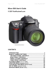
1
Version: 1.07.00
Copyright © 2012, VideoRay LLC - The Global Leader in Micro-ROV Technology
1
Copyright Notice
This material is copyright protected. No material may be reproduced or transmitted in any form or by any means
for any purpose without expressed written consent of VideoRay LLC.
Copyright © 2012, VideoRay LLC - The Global Leader in Micro-ROV Technology
2
Table of Contents
Introduction
About this Documentation
.........8
Glossary
. . . . . . . . . 10
General FAQ
. . . . . . . . . 15
Pro 4 Overview
. . . . . . . . . 17
Quick Start Instructions
. . . . . . . . . 18
Safety First
. . . . . . . . . 19
System Components
. . . . . . . . . 20
Pre-Dive Preparations
. . . . . . . . . 21
Dive Operations
. . . . . . . . . 25
Post-Dive Operations
. . . . . . . . . 26
Equipment Guide
. . . . . . . . . 27
ROV
. . . . . . . . . 28
ROV Connections
. . . . . . . . . 29
Buoyancy
. . . . . . . . . 30
Propulsion
. . . . . . . . . 31
Main Camera
. . . . . . . . . 32
Main Lights
. . . . . . . . . 33
Sensors
. . . . . . . . . 34
Control Panel
. . . . . . . . . 35
Safety Circuits
. . . . . . . . . 36
Switches and Connections
. . . . . . . . . 37
Computer
. . . . . . . . . 40
Panasonic Toughbook
. . . . . . . . . 41
Dell 4500/4600
. . . . . . . . . 42
Monitor
. . . . . . . . . 43
Hand Controller
. . . . . . . . . 44
Help
. . . . . . . . . 46
Joystick
. . . . . . . . . 47
Depth Control
. . . . . . . . . 48
Camera Switch
. . . . . . . . . 49
Camera Tilt
. . . . . . . . . 50
Camera Focus
. . . . . . . . . 51
Lights
. . . . . . . . . 52
Snapshot
. . . . . . . . . 53
Record
. . . . . . . . . 54
Manipulator/Cutter
. . . . . . . . . 55
Lateral Thruster
. . . . . . . . . 56
Tether
. . . . . . . . . 57
TDS
. . . . . . . . . 59
Connections Summary
. . . . . . . . . 61
Accessories
. . . . . . . . . 62
BlueView Technologies
3
. . . . . . . . . 63
Buckley's
. . . . . . . . . 65
Cygnus Instruments
. . . . . . . . . 66
Desert Star Systems
. . . . . . . . . 67
Franatech
. . . . . . . . . 68
KCF Technologies
. . . . . . . . . 69
Lyyn
. . . . . . . . . 70
Tritech International
. . . . . . . . . 71
Turner Designs
. . . . . . . . . 73
YSI
. . . . . . . . . 74
VideoRay
. . . . . . . . . 75
Included Accessories
. . . . . . . . . 76
Optional Accessories
. . . . . . . . . 77
Manipulator
. . . . . . . . . 78
Cutter
. . . . . . . . . 79
Hull Inspection Stabilizer
. . . . . . . . . 80
Lateral Thruster
. . . . . . . . . 81
Laser Scaling Device
. . . . . . . . . 82
Radiation Sensor
. . . . . . . . . 83
External Camera
. . . . . . . . . 84
HD Camera
. . . . . . . . . 85
PAM
. . . . . . . . . 86
TINA
. . . . . . . . . 87
Miscellaneous
. . . . . . . . . 88
VideoRay Cockpit Guide . . . . . . . . . 89
Video Window
. . . . . . . . . 90
Video Text Overlay
. . . . . . . . . 92
Instruments
. . . . . . . . . 94
ROV Health
. . . . . . . . . 96
Control Sensitivity
. . . . . . . . . 97
Compass
. . . . . . . . . 99
Depth
. . . . . . . . . 100
Camera and Lights
. . . . . . . . . 101
Camera Menu
. . . . . . . . . 102
Default Settings
. . . . . . . . . 104
Lens
. . . . . . . . . 107
Exposure
. . . . . . . . . 108
White Balance
. . . . . . . . . 110
Wide Dynamic Range
. . . . . . . . . 111
Day & Night
. . . . . . . . . 113
Image
. . . . . . . . . 114
Special
. . . . . . . . . 115
Camera Title
. . . . . . . . . 116
Communication Adjust
. . . . . . . . . 117
Privacy
. . . . . . . . . 118
Position
. . . . . . . . . 119
Motion Detection
. . . . . . . . . 120
Display
. . . . . . . . . 121
Factory Default
. . . . . . . . . 122
Exit
. . . . . . . . . 123
4
Water Temperature
. . . . . . . . . 124
Turns Indicator
. . . . . . . . . 125
Accessory Instruments
. . . . . . . . . 126
Manipulator/Cutter
. . . . . . . . . 127
Lateral Thruster
. . . . . . . . . 128
Laser Scaling Device
. . . . . . . . . 129
External Camera
. . . . . . . . . 130
LYYN Controls
. . . . . . . . . 131
PAM
. . . . . . . . . 132
Control Bar
. . . . . . . . . 133
Close
. . . . . . . . . 134
Help
. . . . . . . . . 135
Service Bay
. . . . . . . . . 136
Pre-Dive Checklist
. . . . . . . . . 138
Post-Dive Checklist
. . . . . . . . . 139
Scheduled Maintenance
. . . . . . . . . 140
Communications Status
. . . . . . . . . 141
Engine Room
. . . . . . . . . 142
Status Information
. . . . . . . . . 143
Systems Tuning
. . . . . . . . . 144
Compass Calibration
. . . . . . . . . 147
Images and Videos
. . . . . . . . . 148
User Settings
. . . . . . . . . 149
Instrument Settings
. . . . . . . . . 150
System Settings
. . . . . . . . . 152
Depth Sensor
. . . . . . . . . 153
Advanced Depth Settings
. . . . . . . . . 154
Compass
. . . . . . . . . 155
System of Measure
. . . . . . . . . 157
Video Capture and Display
. . . . . . . . . 158
Video Capture Settings
. . . . . . . . . 159
Advanced Video Settings
. . . . . . . . . 160
Data Import
. . . . . . . . . 161
Data Export
. . . . . . . . . 163
Companion Applications
. . . . . . . . . 166
Instrument Display
. . . . . . . . . 167
Software Management
. . . . . . . . . 168
Software Installation
. . . . . . . . . 169
Software Updates
. . . . . . . . . 170
Folder Structure
. . . . . . . . . 173
Application Integration
. . . . . . . . . 174
Operations Guide
. . . . . . . . . 176
Project Management
. . . . . . . . . 177
Mission Planning
. . . . . . . . . 178
General Logistics
. . . . . . . . . 179
On-site Operations
. . . . . . . . . 180
Project Completion
. . . . . . . . . 181
Tether Management
. . . . . . . . . 182
Piloting
. . . . . . . . . 183
5
Auto Depth
. . . . . . . . . 184
Auto Heading
. . . . . . . . . 186
Low Visibility
. . . . . . . . . 187
Swift Current
. . . . . . . . . 189
Deep Water
. . . . . . . . . 190
Images and Videos
. . . . . . . . . 191
Still Images
. . . . . . . . . 192
Video Recording
. . . . . . . . . 193
Video Editing
. . . . . . . . . 194
Video Production
. . . . . . . . . 195
Maintenance Guide
. . . . . . . . . 196
Best Practices
. . . . . . . . . 197
Emergency Situations
. . . . . . . . . 198
Routine Maintenance
. . . . . . . . . 199
Propellers
. . . . . . . . . 201
Cartridge Seals
. . . . . . . . . 202
Example Cartridge Seals
. . . . . . . . . 203
Light Domes or Modules
. . . . . . . . . 204
Camera Domes
. . . . . . . . . 205
Diagnostics and Repair
. . . . . . . . . 206
Power
. . . . . . . . . 207
Communications
. . . . . . . . . 208
Control
. . . . . . . . . 209
Video
. . . . . . . . . 210
Accessories Guide
. . . . . . . . . 212
Integration Overview
. . . . . . . . . 213
Categories
. . . . . . . . . 215
Imagery
. . . . . . . . . 217
LYYN Hawk
. . . . . . . . . 218
External Camera
. . . . . . . . . 219
HD Camera
. . . . . . . . . 220
Intervention
. . . . . . . . . 221
Manipulator
. . . . . . . . . 222
Cutter
. . . . . . . . . 223
Propulsion
. . . . . . . . . 224
Hull Inspection Stabilizer
. . . . . . . . . 225
Lateral Thruster
. . . . . . . . . 226
Sonar
. . . . . . . . . 227
ProViewer
. . . . . . . . . 228
Pole Mount
. . . . . . . . . 229
Gemini
. . . . . . . . . 230
SeaSprite
. . . . . . . . . 231
Position Tracking
. . . . . . . . . 232
Pilot
. . . . . . . . . 233
AquaMap Seafloor
. . . . . . . . . 234
AquaMap Shiphull
. . . . . . . . . 235
Smart Tether
. . . . . . . . . 236
Micron Nav
. . . . . . . . . 237
Micron Echosounder
. . . . . . . . . 238
6
Sensors
. . . . . . . . . 239
Cathodic Protection Probe
. . . . . . . . . 240
C3 Fluorometer
. . . . . . . . . 241
Laser Scaling Device
. . . . . . . . . 242
METS Methane Sensor
. . . . . . . . . 243
Radiation Sensor
. . . . . . . . . 244
Thickness Gauge
. . . . . . . . . 245
600XL Sonde
. . . . . . . . . 246
Integration
. . . . . . . . . 247
PAM
. . . . . . . . . 248
TINA
. . . . . . . . . 249
Customization Guide
. . . . . . . . . 250
This Documentation
. . . . . . . . . 251
Checklists
. . . . . . . . . 253
Hand Controller
. . . . . . . . . 254
Accessories
. . . . . . . . . 255
SDK
. . . . . . . . . 256
Override Mode
. . . . . . . . . 257
Upgrader's Guide
. . . . . . . . . 258
What's New
. . . . . . . . . 259
Pro 3 Upgrader's Guide
. . . . . . . . . 260
System Architecture
. . . . . . . . . 262
Feature Updates
. . . . . . . . . 265
Compatibility Issues
. . . . . . . . . 268
7
About this Documentation
The VideoRay Pro 4 has sophisticated features, but is easy to use and maintain once you learn its capabilities
and the proper operating techniques. This documentation will guide you through your first dive and provide
additional details to help you learn all aspects of its operation.
Document Organization
This documentation is organized into several guides.
The Quick Start Instructions in this section provide the basic steps to get you operational as quickly as
possible while keeping you and the equipment safe.
The Equipment Guide provides details about each component and its function.
The VideoRay Cockpit Guide explains the software features and operation in detail.
The Operations Guide provides tips on how to use the system most effectively.
The Maintenance Guide provides procedures for routine maintenance, diagnostics and repair.
The Accessories Guide provides information about using accessories with VideoRay.
The Customization Guide provides information about customizing the system to better meet your
specific needs.
The Upgrader's Guide provides information about the latest improvements and comparative information
for people who are familiar with the VideoRay Pro 3.
Document Navigation
You can navigate through the documentation to specific topics using the menu, or step through sequentially using
the Next, Previous and Up tabs. The Next tab will step you from the current topic to the next topic at the same
level unless the current topic has a sub-topic. If the current topic has a sub-topic, the Next tab will step you to the
first sub-topic. The Previous tab works similarly, but in reverse sequence. The Up tab can be used to move from
a sub-topic to its parent topic. Additionally, your current location within the document is shown at the top of each
page under the external links. You can click on any level of the hierarchy to go that location.
Inline links are shown in blue bold font.
A PDF version of this document is available for viewing the entire document as a single file or for printing. A
free PDF Reader is available from Adobe.
Document Conventions
Several symbols are used throughout this documentation to add emphasis and to assist in relocating important
information. The following table describes these symbols and their uses.
Symbol
Description
The Danger icon is used to indicate there is a potential risk of personal injury or death. Extra
care should be taken to understand the risks, and all personnel should exercise caution. It may
also be appropriate to warn others in the immediate vicinity.
The Caution icon is used to indicate there is a potential risk of damage to the equipment or
surrounding property. Personnel should receive training in the appropriate procedures before
attempting to operate or maintain the equipment.
The Note icon is used to emphasize a specific detail or point of information.
8
The Tip icon is used to highlight a suggestion.
The Hand icon is used to indicate an interactive element of the page. When you hover your
mouse over the hand icon, an image on the page will change to reflect the information in the
text immediately prior to the hand icon. Try it here - hover your mouse over the following text
and hand icon to turn the hand icon to the left blue: Interactive Text
.
Document Customization - My_Notes
This document has been developed to allow local online versions to be customized using the My_Notes
feature. Users can add their own notes to each page. See the Customizing this Documentation page in the
Customization section for more information about how to customize this document.
Quality Commitment
VideoRay strives to design, manufacture and deliver the highest quality products and services, including this
documentation. We have made every effort to ensure that this documentation is accurate and provides you with
the most effective means to learn how to use your new Pro 4. However, there is no substitute for experience
and/or training, especially with respect to the real purpose for which you plan to use this equipment. We
encourage you to explore options beyond the scope of these materials to expand your knowledge and skills
necessary to support your application. In addition to this documentation, VideoRay offers training and technical
support and hosts a general user discussion forum and user image gallery.
We also realize that collectively, users of our products spend considerably more time operating our systems than
we do ourselves. Users also encounter more diverse operating environments across an extremely broad range
of applications. We highly value this vast experience base, and if you have any questions or suggestions, please
feel free to contact us by any of the following methods.
Address
VideoRay LLC
580 Wall Street
Phoenixville, PA 19460
USA
Email
[email protected]
General Information and Sales
[email protected] Technical Support
Telephone
+1 610-458-3000
Office
+1 610-458-3010
Fax
The information contained herein is deemed accurate at the time of printing and is subject to change without
notice.
9
Glossary
Accelerometer - A device used to measure acceleration - used to determine pitch and roll of the ROV
Accessory - An optional device that can be used with the VideoRay system to augment its features and
capabilities
Accessory Port - ROV connection for ROV mounted accessories that provides access to power and data
circuits
Acoustic - Using sound as a method of communicating underwater - often used to measure distance
AGC - See Automatic Gain Control
Altitude - The height of the ROV off of the bottom
Analog Video Out - Video connector on the control panel for interfacing composite analog displays
APIC - (Auxiliary Pair of Independent Conductors) Also called the Spare Pair (See AUX, AUX Port and Spare
Pair)
Artificial Horizon - See Attitude Indicator
Attitude Indicator - Instrument that provides an indication of the pitch and roll of the ROV
ATW - (Automatic White Balance) color corrects an image - See also White Balance
Audio - In VideoRay context, the ability to record verbal annotation along with the video recording
Auto Depth - Control Feature that maintains the depth of the ROV at a constant value
Auto Heading - Control Feature that maintains the heading (compass direction) of the ROV at a constant value
Automatic Gain Control - Used to manage the intensity of the image - can be adjusted for lighter or darker
images
AUX - Circuit provided for accessories or custom applications (See APIC)
AUX Port - Connector on the control panel that provides access to the AUX circuit (See APIC)
Back Light Compensation - Intentional overexposure to minimize the effects of a bright area in an image
Ballast - Weights used to decrease buoyancy of the ROV to achieve desired buoyancy
Black and White - Image quality using black white or shades of gray only
BLC - See Back Light Compensation
Buoyancy - The tendency to float, sink or remain at a constant depth
Bypass - The Bypass switch allows the system to be used in the event of a Line Insulation Monitor alarm state
(See LIM)
Camera - The camera provides a video image from the ROV
Camera Focus - Method to control image focus or the current state of image focus
Camera Menu - Method to control camera functions
Camera Switch - Method to select whether the internal or external camera is active
Camera Tilt - Method to control the vertical angle of the camera or the current state of camera tilt
10
Cartridge Seal - Component used to lubricate the thruster shaft and seal it from water intrusion
Celsius - Unit of measure of temperature
Checklist - Method to ensure all operations are completed as planned or functions perform as expected
Close - The Close button exits VideoRay Cockpit
Color - Image quality that uses all colors
Compass - Instrument that provides an indication of the heading of the ROV
Compatibility - The state or being able to work together
Computer - Primary topside component required to run VideoRay Cockpit
Control Bar - A VideoRay Cockpit feature that provides access to several functional areas of the software
Control Panel - The surface component that provides power and communications with the ROV
Control Sensitivity - The ability to change the responsiveness of the ROV to the amount of joystick input
Current - The flow of water or electricity
Customization - The ability to change the operation or behavior of the system to make it more suitable for
specific applications
Cutter - An optional ROV mounted device for cutting objects
Data Export - Allows data from the ROV to be exported to external applications
Data Import - Allows data from external applications or sensors to be displayed on the video as overlay text
Date - Calendar Date
DB-15 - Connector style with 15 contacts commonly used for VGA connections
DB-9 - Connector style with 9 contacts commonly used for serial data connections
Deinterlace - Display a video image as two successive scans of alternate rows of the image
Depth - Vertical location of the ROV within the water measured from the surface
Depth Control Knob - Method of controlling the depth of the ROV
Depth Gauge - Display that indicates the current depth of the ROV
Depth Rating - Maximum depth for operation of the ROV
Diagnostics - Method for identifying the cause of a problem
Digital Slow Shutter - Camera feature to improve image in low light situations
Edit - The process of modifying data
ELC - Lens type setting required for optimal image from the VideoRay Pro 4 camera
Engine Room - VideoRay Cockpit interface to access advanced status information and settings
Ethernet - Data Protocol and connector style
Exit - Close the camera menu or VideoRay Cockpit
Export - Method to communicate data from the ROV to other systems
Exposure - Method to control the amount of light captured by the camera
Factory Default - Initial state of a variety of parameters
11
Fahrenheit - Unit of measure of temperature
Fault - Indication of a problem
Feet - Unit of measure of length or distance
Fine - Low power control mode
Firmware - Software that resides on the ROV
Float Block - Required ROV component used to increase buoyancy of the ROV - counteracted by ballast to
achieve desired buoyancy
Gain - Setting to control the level of some parameter
Generator - AC power source that typically runs on gasoline or diesel fuel
GFCI - (Ground Fault Circuit Interrupter) A safety circuit
GPS - (Geographic Positioning System) Device that provides location
Hand Controller - Input device to control the ROV's operation
Heading - The compass direction the ROV is facing
Help - Information intended to provide assistance
Hull Inspection Stabilizer - External device designed to help stabilize the ROV while inspecting ships' hulls
Humidity - Qualitative measure of the amount of moisture in the air
IEC - (International Electrotechnical Commission) Power cord connector standard
Import - Method to receive and process data from other systems
Instrument - VideoRay Cockpit interface feature to display information or control features
Instrument Display - The ability to set an instrument's opacity or turn it on or off
Inverter - AC power source that runs on battery
Joystick - Input device for controlling the surge and yaw of the ROV
Lens - Camera element used to capture and focus light to create an image
Lights - ROV component that provides lights for scene illumination in dark areas
Light Dome - Protective covering over the lights
LIM - (Line Insulation Monitor) A safety circuit
Main Dome - Protective covering over the camera
Manipulator - An optional ROV mounted device for grabbing objects
Meter - Unit of measure of length or distance
Mission Planning - A method to prepare for a successful ROV operation
Monitor - Device used for the display of the video or computer image
Mute - The ability to silence the audio recording
My_Note - Feature of the documentation that allows users to add personal notes to the online pages
Negative - A state of buoyancy in which the ROV will sink and a type of tether
Neutral - A state of buoyancy in which the ROV will maintain it's vertical location and a type of tether
12
O-Ring - Sealing device
Opaque - Unable to see through
Overlay - Text or logo superimposed on the video
PAM - (Protocol Adapter Multiplexer) A programmable interface device
Pitch - The nose-up or nose-down attitude or motion of the ROV
Positive - A state of buoyancy in which the ROV will float and a type of tether
PPT - (Professional Performance Tether) A type of tether
Pressure Sensor - A device to measure pressure - used to calculate ROV depth
Propeller - ROV component with pitched blades that generate thrust when rotated
RCA - Connector style commonly used for composite analog video
Record - Command to initiate video capture to a storage media
Remotely Operated Vehicle - The underwater vehicle
RJ-45 - A connector Style with 8 contacts commonly used for Ethernet connections
Roll - The left or right leaning attitude or motion of the ROV
ROV - See Remotely Operated Vehicle
ROV Health - An instrument that provides feedback on the status of several critical ROV systems
RS-485 - Data Protocol
Safety - State of, or application of, safe practices
SDK - (Software Developer's Kit) A program and a set of software libraries and utilities to aid custom program
development
Sensitivity - The amount of output based on a specific level of input, particularly for the joystick
Sensor - An instrument for measuring a specific property of an object or the environment
Service Bay - VideoRay Cockpit interface that provides diagnostic information and checklists
Settings - The values of specific controls or parameters, or the ability to manage these
Skid - The base of the ROV and often used to mount accessories
Software Developer's Kit - See SDK
Snapshot - A still image captured from the video image
Spare Pair - Extra pair of conductors in the tether - See also APIC
Strain Relief - An ROV and tether component that reduces the load on tether connections
Sun Shade - Device used to shade the display for better visibility in direct sunlight
Surge - The forward and backward motion of the ROV
TDS - (Tether Deployment System) A reel for storing tether
Temperature - Qualitative measure of hot or cold
Termination Block - ROV component that connects the ROV to the tether
Tether - The cable that connects the ROV to the control panel
13
Tether Deployment System - See TDS
Text Overlay - Ability to superimpose text over a video image
Third Axis - Rotational motion of the joystick - can be used as an alternate control method of the joystick
Thruster - ROV propulsion system including a motor and propeller
Thruster Cartridge Seal - Seals the thruster shaft from water intrusion
Thruster Nozzle - Shroud around the propeller
Tilt Arm - Control panel component to adjust the angle of the optional second monitor
TINA - (Tether Interface Node Adapter) A device that allows accessories to be connected directly to the tether
without the ROV
Transparent - Ability to see through
Turbo - High power control mode
Turns Indicator - An instrument that keeps track of the number of rotations of the ROV about its vertical axis
and provides information on which direction to turn to unwind the tether
Umbilical - See also Tether
Upgrade - A newer version or the process of installing a newer version
USB - (Universal Serial Bus) Data protocol and connector style
User Settings - VideoRay Cockpit interface to access operating parameters
VGA - Video Graphics Array) Video format and connector style
Video - In VideoRay context, the image from the ROV's camera or the ability to record this image
Video Encoder - Defines a method of storing a video image within a file format
Video Window - Display component that displays the video image from the camera
VideoRay Cockpit - VideoRay ROV control program
VideoRay Data Folder - Destination folder for video recordings and snapshots
VideoRay Update - Software program to upload new firmware to the ROV
Virtual COM Port - A software feature that allows two applications on the same computer to communicate
without requiring physical ports
Visibility - Measure of the clarity of water
WDR - See Wide Dynamic Range
Whip - A short length of tether attached to the ROV or control panel
White Balance - Camera feature to color correct images from the camera
Wide Dynamic Range - Camera feature to improve image in high contrast lighting situations
Yaw - The left or right turning attitude or motion of the ROV
Zoom - Camera image magnification
14
FAQ (Frequently Asked Questions)
New users typically have some pretty basic questions about the Pro 4. Before getting to the details, this section
is provided to address the questions asked most frequently, without having to scan through the manual to find the
answers. Additional questions and answers are available online at www.rovfaq.com, which is also linked at the
top of this page.
1. How hard is it to learn how to operate the Pro 4?
The Pro 4 is easy to learn to operate. In a few hours, user should be able to pilot the ROV confidently in
clear, calm water and know enough about it to maintain it in good condition for years. However, mastering
all the knowledge and developing the skills to be able to pilot the ROV in much more demanding
situations with near zero visibility and swift current will require more experience. See the Quick Start
Instructions for more information.
2. How deep can the Pro 4 go?
The rated depth of the Pro 4 is 300 meters (1000 feet).
3. How fast can the Pro 4 go?
The rated speed of the Pro 4 is 4.2 knots.
4. In how much current can the Pro 4 operate?
While the logical answer seems to be that it can not operate in current faster than the vehicle can go in
calm water, operational tactics can be used to operate in current that exceeds the maximum speed of the
ROV. See the Piloting in Current section of the Operations Guide for more information.
5. How much can you pick up with the Pro 4?
The Pro 4 manipulator closes with about 4.5 kilograms (10 pounds) of force, and the vehicle has limited
vertical thrust. However, if you can grab a secure hold of an object, you can retrieve it by pulling on the
tether. Items weighing up to 20 kilograms (80 pounds) in water have been successfully retrieved. See the
Tether section in the Equipment Guide for more information.
6. How much tether can you use with the Pro 4?
The maximum tether length is about 600 meters (2000 feet). Tether is like conventional electric extension
cords and multiple sections can be plugged in together. See the Tether section in the Equipment Guide
for more information.
7. How do you adjust the buoyancy and trim of the Pro 4?
The buoyancy and trim can be adjusted by opening the skid pod and adding or removing the brass ballast
weights. See the Pre-Dive Preparations section of the Quick Start Instructions for more information.
8. Can you record pictures and video from the Pro 4?
Pictures and videos can be recorded in digital format on the computer. There is also an analog out
connector for recording to standard analog devices that accept a composite video signal. See the
Images and Videos section in the Operations Guide for more information.
9. Can you record topside audio for narration?
Topside audio can be recorded along with the video file. Audio can be muted while recording to eliminate
15
background noise. See the Video Window section in the VideoRay Cockpit Guide for more
information.
10. Can you import data from other systems?
Data from sensors or other systems can be imported into VideoRay Cockpit and displayed on the video
as overlay test. See the Data Import section in the VideoRay Cockpit Guide for more information.
11. Can you export data from the Pro 4?
Data from the VideoRay Pro 4 sensors can be exported to other systems via a COM port in real time or a
file for post processing. See the Data Export section in the VideoRay Cockpit Guide for more
information.
12. How much maintenance is required for the Pro 4?
The Pro 4 is easy to maintain. There are very few consumable parts, and these have been designed to be
as easy to replace as possible. Cleaning the vehicle after each use is one of the most important
maintenance requirements. See the Routine Maintenance section of the Maintenance Guide for more
information.
16
VideoRay Pro 4 Overview
VideoRay is pleased to present the latest model in its top-of-the line professional series Micro-ROVs - the
VideoRay Pro 4. Like the Pro 3, the Pro 4 was designed for performance and maintainability, but has entirely new
internal electronics, including camera, LED lights, processor, and added sensors. With powerful brushless
motors, the Pro 4 further extends VideoRay's position as the fastest and most powerful tether pulling vehicle.
Additional improvements include deeper depth rating, hydrodynamic streamlining, and optimized ballast
adjustment. Topside control is based on industry standard rugged computers, with new software that integrates
several functions while dynamically reconfiguring for ease of use.
The Pro 4 submersible builds on VideoRay's strengths with more than twice the vertical thrust of the Pro 3, and
50% greater horizontal thrust. A depth rating of 300 meters (1000 feet) is standard. Improvements in the
electronics allow for both greater total tether length up to 600 meters (2000 feet) and much better power
transmission over longer tethers. Existing VideoRay tethers can be used with the Pro 4 - and different tether
types can still be combined to meet different operational requirements. New sensors, including 3 axes compass
and accelerometers and MEMS gyro improve navigational capabilities. The primary video camera features ultra
low light and Wide Dynamic Range imaging capability, with a wide range of user controllable parameters for
demanding imaging situations. Coupled with the very high intensity LED lighting, the images and video that can
be captured are far clearer, particularly in difficult lighting conditions. A second camera can be rotated 270
degrees to provide lateral views as needed.
The topside control configuration replaces inflexible and limited switches and knobs with context-sensitive
controls that go beyond simply controlling the submersible to controlling navigation, sonar, image and video
capture, and other sensors and accessories in addition to the submersible. This "systems approach" significantly
reduces operator workload and distraction caused by separate systems for sonar, navigation, video capture, and
vehicle control.
The Pro 4 is part of an industry-wide initiative led by VideoRay (the largest volume ROV manufacturer in the
world) to go beyond separate "point" technology solutions to a "systems" approach to solving underwater tasks.
The Pro 4 series ROVs are packaged in configurations such as the PS (Port Security Configuration) and CD
(Commercial Dive Configuration) designed to solve a specific or series of underwater tasks, with VideoRay
providing comprehensive solutions across the many technologies involved. Users will be able to concentrate on
their underwater missions, not which technology works together and how are the pieces fit together.
Additionally, VideoRay recognizes that technology is only as good as the people who use it. Successful
organizations focus on training and systematic procedures for operations and maintenance. The VideoRay Pro 4
package includes features that help owners and operators develop, implement and execute ROV operations and
maintenance programs more efficiently and effectively. These features include customizable documentation,
online interactive operating checklists and knowledge and skill assessment tools. Companies with one system or
an entire fleet can leverage these capabilities to ensure that their investment in VideoRay equipment continues to
return value throughout its life.
17
Quick Start Instructions
These Quick Start Instructions are streamlined to cover just the essentials of operating your Pro 4. They are
provided to get you started as fast as possible, while keeping you and the equipment safe. They cover the
equipment set up and basic operation, but are not intended to result in a comprehensive base of knowledge or
set of operational and piloting skills. The remaining sections of this documentation should be referenced for a
complete understanding of the features, capabilities, operating procedures and maintenance requirements of the
Pro 4.
While you will likely find the Pro 4 easy to pilot, we strongly recommend that your first dive be conducted
in a controlled environment such as a small tank or pool. As you gain experience with your system and
confidence in using it, you will be able to operate in more challenging conditions that might include low visibility,
currents and potential hazards that could snag your tether or trap your ROV.
Topics in this Section
Safety First
System Components
Pre-Dive Preparations
Dive Operations
Post-Dive Operations
18
Safety First
Operating electrical devices in and near the water can be dangerous. There is
always a risk of drowning or electrocution in such an environment. Reduce these risks by using common sense
and observing safety regulations and recommended safe practices including the following:
Never handle power cords while in contact with water or allow power cord connectors or the control panel
to enter the water. The only components that can safely be placed in water are the submersible, any
onboard accessories and tether, and only after making sure the connections are secure.
Always test the GFCI (Ground Fault Circuit Interrupter), and LIM (Line Insulation Monitor) before beginning
operations. Follow the procedures described later in these Quick Start Instructions.
Have proper safety equipment, such as PFDs (Personal Flotation Devices), on hand and make sure you
know how to use them before you need them.
Keep fingers, hair, loose clothing and other objects away from VideoRay's propellers.
Be aware of and follow any legal ordinances or regulations in your area regarding operation of vessels
and underwater equipment in the water.
Monitor weather and sea conditions and heed any warnings or alerts.
Before setting up for or commencing any dive, it is a good practice to make sure there are no hazards to
people or the equipment on land or in the water. If there are other people in the water nearby, you should advise
them that you are going to be operating the ROV. As the owner/operator, it is your responsibility to ensure the
safety of those around you as well as that of the equipment and nearby property.
19
Introduction to the System Components
Unpack the system and familiarize yourself with the components.
ROV
The ROV, or Remotely Operated Vehicle, carries the cameras, lights
and sensors or accessories to the underwater places you want to
observe. Thrusters provide mobility and these systems are controlled
from the surface using the control panel and hand controller.
See the ROV section of the Equipment Guide for more information.
Control Panel
The control panel includes the system's power and communications
modules, computer and hand controller, and serves as the operator's
console and video display. Open the control panel and familiarize
yourself with the components and primary controls on the hand
controller. See the Control Panel and Hand Controller sections of
the Equipment Guide for a complete description of all of the controls
and connections.
See the Control Panel section of the Equipment Guide for more
information.
Hand Controller
The hand controller is used to pilot the VideoRay and operate other
features like the lights, camera controls and manipulator. The hand
controller is pre-programmed, but can be customized to meet specific
user or operational needs.
See the Hand Controller section of the Equipment Guide for more
information.
Tether / TDS (Tether Deployment System)
The tether connects the ROV to the control panel. It delivers power
and control signals to the ROV, and returns video and sensor data
(optional) from the ROV to the surface. Some systems come with a
TDS (Tether Deployment System), that makes the work of managing
the tether easier. The tether is also often referred to as the umbilical.
See the Tether section of the Equipment Guide for more information.
Some items shown are optional and not included with all models.
20
Pre-Dive Preparations
Select a safe and preferably level area to set up the control panel. See the On-site Operations section
of the Project Management Guide for more information about site selection and set up.
The pre-dive preparations consist of three parts, a visual inspection before setting up the system, setting up the
system including making connections, and power on tests of the system's safety circuits and primary functions.
VideoRay Cockpit includes an online interactive Pre-Dive checklist. See the Pre-Dive Checklist section of the
VideoRay Cockpit Guide
Conduct a Visual Inspection
Assuming this is your first time using the VideoRay, everything should be in proper working order and ready to
go, but it is good practice to perform a pre-dive inspection before every dive, even your first. If any problems are
noticed, refer to the Diagnostics and Repair section of the Maintenance Guide and take appropriate
corrective action, or contact VideoRay for assistance before commencing the dive.
1. Inspect the ROV and other system components to make sure there are no visible signs of damage or
loose or warn parts. Also check for water inside the ROV hull by holding it with the front facing downward
and look for signs of water in the main dome or light domes.
2. Check the horizontal thrusters to make sure that the shafts are not bent and the propellers are free to spin
and are not fouled, loose or binding on the thruster guards. Check the thruster cartridge seals - they are
filled with oil and there should be no signs of leaking or contamination. A small air bubble in a thruster
cartridge seal is acceptable. See the Maintenance Guide for warnings, replacement criteria,
examples and replacement procedures.
3. Check the vertical thruster to make sure the shaft is not bent and the propeller is not fouled or loose or
binding on the float block. Also, check the thruster cartridge seal following the same guidelines used to
check the horizontal thruster cartridge seals. Make sure the accessory port at the rear of the ROV is
sealed with either a connector from an attached accessory or an accessory port terminator plug. Removal
of the float block by loosening the retaining screw may facilitate this process.
Make the Connections
Connecting or disconnecting cables while the system is powered on is not recommended.
Most of the cables have been connected at the factory. See the appropriate sections of the Equipment Guide
for detailed information about each of the connections.
You will typically need to connect only the hand controller, tether and power cord.
1. Connect the hand controller to one of the USB ports on the back of the control panel or directly to one of
the USB ports on the computer.
2. Connect the female end of the tether connector to the ROV. The connectors have one pin that is offset
towards the center of the connector. Make sure the connectors are clean, align the pins, and push the
connectors together - do not twist the connectors. Secure the locking collar by screwing the halves
together, and connect the strain relief cable from the ROV to the braided strap on the tether.
3. Connect the male end of the tether to the control panel. When not in use, keep the tether connectors
clean and protected for the best performance and reliability.
4. Plug the control panel power cord into a conventional power source (100-240 Volts AC, 50,60 Hz). Power
can be supplied through a land-based power outlet, generator or battery and inverter. See the Control
21
Panel section of the Equipment Guide for power source requirements.
Power On Tests
If the system does not pass any of the following tests, it should not be used until
the problem is identified and corrected. See the Diagnostics and Repair section of the Maintenance Guide
for more information.
The VideoRay Pro 4 includes two circuit safety components.
The GFCI (Ground Fault Circuit Interrupter) / Circuit Breaker
LIM (Line Insulation Monitor) Test and Reset buttons can be found on the front right side of the control
panel.
Testing the Circuit Safety Components
Test the GFCI / Circuit Breaker switch (The system must be connected to a working power source to perform this
test.)
1. Set the GFCI / Circuit Breaker switch to the On position.
2. Press the test switch labeled with an embossed "T." The GFCI / Circuit Breaker switch should turn off.
3. Set the GFCI / Circuit Breaker switch to the On position.
Set the Power switch to the On position. The green Power On indicator light should turn on. If the green Power
On indicator light is not on, make sure the system is connected to a working power source and the GFCI / Circuit
Breaker switch is turned on.
Test the Line Insulation Monitor (GFCI / Circuit Breaker switch and Power switch must both be set to On in order
to perform this test.)
1. The yellow Alarm light should be off. If the yellow light is on, press and hold the black Reset button until
the yellow Alarm light turns off.
2. To test the LIM, press and hold the red Test button until the yellow Alarm light turns on. This may take up
to 10 seconds. Release the button when the yellow Alarm light turns on.
3. Press and hold the black Reset button to reset the LIM. The yellow Alarm light should turn off. Release
the button when the yellow Alarm light turns off.
Starting VideoRay Cockpit Control Software
Make sure the system is connected to a working power source and the GFCI / Circuit Breaker and Power
switches are turned on.
1. Turn on the computer and wait for the system to complete the boot up process.
2. After the computer has started, start VideoRay Cockpit using the desktop icon, or by selecting it from the
Start->All Programs->VideoRay menu.
3. When VideoRay Cockpit starts, you will see the Video Window
, the Control Instruments
and the
Control Bar . For now, you will only need to focus on the video window. See the VideoRay Cockpit
Guide for details about using VideoRay Cockpit.
22
VideoRay Cockpit screen with simulated video image - your image will likely be different.
Testing the System's Functions
The next step is to ensure that the essential features of the ROV are functioning properly. Use the hand controller
to perform the following tests. See the Hand Controller section of the Equipment Guide for more information
about using the hand controller.
Joystick
Depth Control knob
Lights Bright button
Lights Dim button
Camera Tilt Up button
Camera Tilt Down button
Camera Focus In button
Camera Focus Out button
For the next two steps, do not operate horizontal thrusters out of water for more than 30 seconds
to avoid overheating or premature wear of the cartridge seals.
1. Gently move the joystick forward and backward and left and right - the horizontal thruster motors should
turn the propellers. Release the joystick - it will return to center on its own, and the propellers will stop
turning.
2. Rotate the Depth Control knob - the vertical thruster motor should turn the propeller. Return the Depth
Control knob to center to cease the vertical propeller rotation.
For the next two steps, do not leave the lights on bright for more than 30 seconds while the ROV
is out of water to avoid overheating.
1. Press and hold the Lights Bright button to increase the intensity of the lights - the lights should get
brighter.
2. Press and hold the Lights Dim button to dim the lights - the lights should dim.
Test the camera functions.
23
1. Press and hold the Camera Tilt Up button - the camera should tilt up smoothly through its entire range.
2. Press and hold the Camera Tilt Down button - the camera should tilt down smoothly through its entire
range.
3. Press and hold the Camera Focus In button - the camera should focus in smoothly through its entire
range.
4. Press and hold the Camera Focus Out button - the camera should focus out smoothly through its entire
range.
If a manipulator or other accessories are attached, these items should be checked at this time.
24
Dive Operations
After all of the pre-dive checks and tests have been completed successfully, you are almost ready to commence
the dive. But, there is one more issue to address that could affect the performance of the ROV. The ROV is
designed to be operated in a near neutrally buoyant configuration, so the last step before launching your
VideoRay is to check the buoyancy. For most operations, the buoyancy is optimal when the top of the float block
is even with the water surface and the ROV is level. If the ROV is to buoyant or heavy, the vertical position may
be hard to maintain or control.
Buoyancy Check and Adjustment
To determine if the buoyancy is correct, lower the ROV and at least 3 meters (10 feet) of tether into the water.
You can lower the ROV by the tether - it will not hurt the tether because there is Kevlar in it. Observe the ROV in
the water - it should not be floating too high or sink. It should also be floating level and not tipped to one side or
pitched up or down. If the ROV floats too high, you will need to add some ballast weights. If the ROV sinks, you
will need to remove some ballast weights. If the ROV is not floating level, you can change the locations of the
weights.
The buoyancy can be adjusted by opening the skid pods and adding or removing the supplied ballast weights. To
open the skid pods, turn the ROV upside down. Unhook the retaining o-ring on the end of the pod, and lift up on
the pod. The weights can be added to or removed from the slots by hand. For most operations, the weights
should be evenly distributed.
Buoyancy will need to be adjusted for use in fresh water versus salt water and depending upon whether
accessories are used with the ROV.
Commence the Dive
Once the buoyancy has been adjusted the ROV is ready to launch. Lower it into the water and operate the
controls to maneuver it.
Start with the ROV on the surface and push the joystick forward slightly to make the ROV move forward.
Move the joystick to the left or right to make it turn left or right. Get a feel for how agile the ROV is.
Observe the video display as well as the ROV to become acquainted with the camera's wide angle lens
and its affect on depth perception underwater.
Once you feel comfortable with the horizontal maneuverability of the ROV, rotate the depth control knob to
dive the ROV. Tilt the camera down as you dive so you can see towards the bottom. Rotate the depth
control knob to bring the ROV back to the surface. Tilt the camera up as you surface so you can see
towards the surface.
Change the lights settings, and adjust the camera focus. If you have a manipulator, tilt the camera down
so you can see it and open and close the jaws.
As you get familiar with maneuvering the ROV, you can start to observe some of the on-screen displays
including the depth, heading, camera settings and other data.
For your first dives, practice until you are comfortable operating the controls without looking at them and you are
able to control the ROV with some precision.
See the Hand Controller section of the Equipment Guide for complete information about using the
hand controller and see the Piloting section of the Operations Guide for more advanced tips on piloting the
Pro 4.
25
Post-Dive Operations
At the conclusion of your dive, retrieve the VideoRay and power down the system by closing VideoRay Cockpit,
shutting down the computer and turning off the Power switch and then the GFCI / Circuit Breaker switch. Make
sure the ROV is secure before disconnecting the tether. After disconnecting the tether, keep the tether
connectors clean and do not let them drag on the ground.
Proper maintenance of your VideoRay system ensures a long service life and that it will be ready to operate
when you are. After each dive, you should visually inspect the system for damage that might have occurred
during your operation.
VideoRay Cockpit includes an online interactive Post Dive checklist. See the Post Dive Checklist section of the
VideoRay Cockpit Guide
Keeping the ROV clean is one of the most important aspects of good preventative maintenance practices,
especially after using it in salt water. If you use your ROV in salt water, or water with contaminants, you should first
rinse it, and then soak it in clean fresh water for at least one-half hour. After cleaning the ROV and tether, they
should be allowed to air dry before being put away for storage.
Failure to properly maintain the ROV by thoroughly cleaning it after use may dramatically reduce
its service life.
Debriefing
Congratulations! You are well on your way to becoming an accomplished micro-ROV operator, but there are still
many things to learn and skills to master. Continue learning about the system by reviewing the additional sections
of this documentation and, most importantly, practice, practice, practice.
If you encountered any difficulties or have any questions, review these Quick Start Instructions and the other
documentation that came with your system, including the Equipment and Maintenance guides. If you still have
difficulty or questions, contact VideoRay. Your success is our success, and we are here to help you get the most
out of your VideoRay.
VideoRay contact information is available in the About this Documentation section of the Introduction.
26
Equipment Guide
Understanding the features and capabilities of the Pro 4 equipment is essential to get the most value out of using
the system. The sections within this Equipment Guide provide details about each of the components.
Topics in this Section
ROV
Control Panel
Hand Controller
Tether
Connection Summary
Accessories
27
ROV
The Pro 4 ROV (Remotely Operated Vehicle) is depth rated to 300 meters (1000 feet).
Thrusters provide mobility and are controlled from the surface using the hand controller. The ROV carries
cameras, lights and other sensors to the underwater locations being searched, explored or inspected.
The primary ROV components are illustrated below. Note that the yellow float block and clear vertical thrust
splitter have been removed from the top of the ROV.
28
ROV Connections
The ROV includes the following connections:
Connection
Type
Function
Tether Whip (View
Specifications)
8 pin round male
Used to connect the ROV to the tether for power,
communications, video and accessory support.
Accessory Port
(Specifications listed below)
9 pin rectangular
female
Provides power, communications and video. Can be used to
connect accessories electrically to the ROV.
Accessory Port
The ROV accessory port provides power, access to the ROV communications bus and the APIC (Auxiliary Pair
of Independent Conductors) to the surface. Most accessories, with the exception of the manipulator and cutter,
use a stackable pass through connector that allows multiple accessories to be connected to the accessory port
in parallel.
The accessory port must be sealed with a terminated accessory connector or the accessory port
terminator dummy plug. Failure to seal the accessory port may lead to loss of control of the ROV or damage to
the components.
Accessory Port Specifications
Pin
Function
1
Video -
2
Video +
3
24 VDC + (30 Watts*)
4
Aux + (APIC) Connects to tether pin 4 and control panel AUX port pin 7
5
Power Common (Ground)
6
Aux - (APIC) Connects to tether pin 6 and control panel AUX port pin 8
7
RS-485 -/A
8
RS-485 +/B
9
12 VDC + (30 Watts*)
29
Buoyancy and Depth Control
The weight of the vehicle in water is offset by the air inside the hull and the float block on the top of the ROV.
Ballast weights can be added or removed to achieve the desired buoyancy. Buoyancy can be affected by fresh
or salt water and the buoyancy of any accessories that might be mounted on the ROV.
The depth of the Pro 4 is controlled by a vertical thruster. For the thruster to operate efficiently, the buoyancy of
the ROV should be near neutral. This can be accomplished by adding or removing ballast weights that are stored
in the skid pods on the bottom of the ROV. The skid pods are hinged at the rear and can be opened by
unhooking the O-ring at the front. Turn the ROV over on its top to add or remove ballast. The ballast weights can
be positioned within the skid pods to trim the ROV level, or pitched slightly up or down.
The procedures to adjust the buoyancy are described in the Dive Operations section of the Quick Start
Instructions.
30
Propulsion
ROV Propulsion is provided by two horizontal thrusters and one vertical thruster that are controlled from the
surface using the joystick and depth control knob on the hand controller. Each thruster motor turns a propeller to
create the desired thrust.
Each thruster shaft is sealed with a cartridge seal to prevent water intrusion. These cartridge seals are filled with
oil and will wear out over time. Worn cartridge seals need to be replaced. Inspection consists checking the
amount of oil, and for any signs of contamination or other signs of wear. When the oil level is less than half of the
volume of the cartridge seal, the seal should be replaced.
Based on service records at VideoRay, the most frequent cause of ROV failure is the failure of
the operator to inspect the thruster cartridge seals and replace them as necessary.
In additional to manual piloting, the VideoRay Cockpit control software provides two pilot assist modes, Auto
Depth and Auto Heading. Auto Depth and Auto Heading are described in the Operations Guide.
The horizontal thrusters use counter rotating propellers to avoid torque induced roll while thrusting and for better
performance. Additionally, VideoRay Cockpit includes variable control sensitivity and power management to
further tune the performance of the thrusters.
Avoid contact with the propellers or getting hair, clothing or other objects in the
propellers.
31
Main Camera
The ROV includes a main camera in the front of the main hull, which can be tilted and focused from the surface
using the hand controller. Panning the camera is accomplished by turning the ROV.
The camera has numerous features including the following highlights:
Switchable between Color and Black and White
Automatic White Balance
Wide Dynamic Range
Back Light Compensation
Digital Slow Shutter
1 - 2.5X Zoom
The complete list of camera features and how to control them are described in the Camera Menu section of the
VideoRay Cockpit Guide
The video circuit in the ROV is switchable between the main camera and a video conductor pair on the ROV
accessory port. This allows external cameras to be used as well, but only one camera can be viewed at a time
when using this method.
The ROV, control panel and tether, also support an APIC (Auxiliary Pair of Independent Conductors) that
can be used to provide a second simultaneous video feed.
The main camera resides behind an acrylic dome. The dome should be cleaned with soap and
water. Do not use products that contain alcohol, because this can create stress cracks in the dome.
The front and rear domes are the same and can be interchanged. If the front dome is scratched, the rear
dome can be moved to the front.
32
Main Lights
The ROV uses two forward facing variable LED light modules that can be controlled from the surface using the
hand controller. The lights produce 3,600 lumens. The beam pattern is optimized to minimize glare in the main
camera dome and provide maximum vertical coverage.
33
Sensors
In addition to the camera, the ROV includes several other sensors that provide feedback to the pilot about the
ROV and the environment it is in.
ROV sensors include:
Pressure Sensor - Indicates the depth of the ROV.
3 Axes Compass - Indicates the heading of the ROV
3 Axes Accelerometers - Indicates the attitude of the ROV
Water Temperature - Indicates the water temperature of the water surrounding the ROV.
Internal Temperature - Indicates the internal temperature of the ROV.
Internal Humidity - Indicates the relative humidity of the air inside the ROV.
The information provided by these sensors is conveyed to the pilot via instruments in VideoRay Cockpit, and
some items including the depth, compass heading and temperature can be overlaid on the video.
The Depth and Temperature units are user selectable. See the System Settings tab of the User Settings
for information on how to select the system of units.
Do not put anything in the pressure sensor cavity or spray a strong stream of water into the
pressure sensor cavity. Doing so may damage the pressure sensor.
34
Control Panel
The control panel provides power, communications and a video interface between the surface and the ROV
through the tether. The computer, which runs VideoRay Cockpit software to control the ROV is housed in the
control panel along with a second display monitor.
Control Panel Power Specifications
The VideoRay Pro 4 operates on typical residential power in the range of 100-240 Volts AC, 50,60 Hz. This can
be provided from the land-based grid, a generator, or a battery with an inverter. The typical power requirements
for operating from a generator or inverter are 600 Watts minimum. VideoRay supplies an inverter with the Pro 4.
For sales to locations that do not support U.S. style power cords, VideoRay also provides universal IEC adapter
cords with the inverter.
The system includes a GFCI (Ground Fault Circuit Interrupter) / Circuit Breaker to protect the operator.
There are two universal IEC power outlets on the back of the control panel. These outlets are protected by the
GFCI. The GFCI must be on to use these outlets, but the control panel power switch does not need to be on.
The power in the tether is 74 Volts DC. This circuit is protected by a LIM (Line Insulation Monitor).
The procedures for testing the circuit safety components can be found in the Pre-Dive Preparations section of
the Quick Start Instructions.
Display Monitor Tilt Arm
The Display Monitor Tilt Arm on the left side of the panel can be used to adjust the angle of the control panel lid,
which houses the second monitor. To adjust the angle of the lid, loosen the locking collar, adjust the lid to the
desired angle and tighten the locking collar.
Make sure to loosen the display monitor tilt arm before closing the control panel lid, and be careful
when closing the lid to avoid damaging the computer or monitor or pinching any cables.
Do not block the fans. Blocking the fans can lead to overheating and component failure.
35
Safety Circuits
The Control Panel includes two circuit safety components.
GFCI (Ground Fault Circuit Interrupter) / Circuit Breaker
LIM (Line Insulation Monitor)
See the Pre-Dive Preparations section of the Quick Start Instructions for information on testing these
components.
GFCI (Ground Fault Circuit Interrupter) / Circuit Breaker
The GFCI / Circuit Breaker protects the operator from shock from the AC circuit of the power source, and
protects the equipment from a current overload. The GFCI has two operating switches and a test button. To
energize the control panel, both switches need to be turned on. If the GFCI detects a differential current between
the supply and ground poles of the power source, it will trip, or open the circuit. If the circuit breaker detects a
current greater than it's rating, it will trip. The test button can be used to simulate these conditions and pressing
and holding the test button should cause the switches to open, or turn off. If the GFCI continues to trip, the
system should be inspected for a fault before being used.
LIM (Line Insulation Monitor)
The LIM protects the operator from shock from the DC circuit of the tether. While the GFCI switches are part of
the GFCI component and must be turned on to operate the control panel, the LIM switches are separate
components and the LIM does not need to be turned on. The LIM switches include Reset and Test. When power
is applied to the control panel, the LIM is active. The LIM operates on a principle similar to the GFCI and detects
differential current. If the differential current exceeds a threshold, the LIM will trip. When the LIM trips, the yellow
LIM Alarm LED will turn on. The LIM can be reset by pressing and holding the Reset button. The LIM may take
several seconds to reset. The yellow LIM Alarm light should turn off. To test the LIM, press and hold the Test
button. It may take several seconds to trip. If the LIM continues to trip, the system should be inspected for a fault
before being used.
LIM Bypass
In some situations, the LIM may trip, but the system may in fact be safe to use. A common situation that may
cause the LIM to trip is using an old tether that has some current leak at its connectors. The LIM is sensitive
enough to detect this leak. If it is determined that the cause of the LIM tripping does not represent a potential
hazard to the operator or people in the surrounding area, the LIM can be bypassed to continue operations. The
LIM can be bypassed by engaging the LIM Bypass switch to the Bypass setting. The LIM Bypass switch is a
locking switch and the stem of the switch must be pulled out to switch it. When the LIM is set in Bypass mode,
the RED LIM Bypass LED will turn on indicating the system may be unsafe to operate.
Determining if the system is safe to operate in the LIM Bypass mode requires a trained and
qualified technician. Do not operate the system in LIM Bypass mode unless you are trained and qualified and
100% certain that the situation is safe.
36
Switches and Connections
Control Panel Top
Control Panel Rear
The control panel includes the following switches:
Switch
Location
Function
GFCI/Circuit
Breaker
Control
panel top
Turns on the power outlets and enables the power switch.
Power
Control
panel top
Turns the control panel on.
LIM Test
Control
panel top
Test the LIM by simulating a fault and triggering the alarm state.
LIM Reset
Control
panel top
Reset the LIM after a test or a fault has been detected and the alarm state has
been triggered.
37
LIM Bypass
Control
panel rear
If the LIM alarm state has been triggered, the LIM can be bypassed by enabling
this switch.
If the LIM bypass switch is enabled, LIM protection is disabled.
This situation can pose a risk to people handling the tether or in the water with
the ROV. Do not use the LIM bypass switch unless you have examined the
system to make sure it is safe, or are sure that people are not going to be
exposed to a possible voltage leak in the tether or ROV.
AUX Port
Selector Switch
(Optional)
Control
panel rear
Switches the APIC circuit between the AUX Port and a dedicated accessory
interface, such as an Ethernet connector, if one is included.
The control panel includes the following connections:
Connection
Power (100-240 Volts AC,
50, 60 Hz)
Type
IEC male
Function
Used to connect the control panel to a power source.
GFCI/Circuit Breaker
IEC
Protected Power Outlets (2) female
Used to connect the computer and another device to the control
panel to receive power.
Tether Whip
(Specifications)
Used to connect the control panel to the tether for power,
communications, video and accessory support.
8 pin
round
female
Monitor Power
Provides 12 Volts DC. Used to provide power to the monitor.
Analog Video Out
RCA
female
Provides a composite video signal. Can be used to connect an
analog video recording device.
USB PC
Type B
female
Used to connect the control panel to the computer.
USB Accessories (3)
Type A
male
Can be used to connect USB devices to the computer via the control
panel.
AUX Port (Specifications
listed below)
DB-9 male Provides access the APIC (Auxiliary Pair of Independent
Conductors) in the tether. Can be used with ROV accessories that
need to rely on the APIC for communications.
Ethernet (Optional)
RJ-45
female
BlueView Pole Mount
(Optional)
Can be used to connect the control panel to the computer for
Ethernet based ROV accessories.
Used to connect the BlueView Pole Mount system to the control
panel.
AUX Port Specifications
Connector Type - DB-9 Male.
Pin
Function
1
No connection
2
No connection
3
No connection
4
No connection
5
No connection
6
No connection
7
AUX + (Connects to tether pin 4 and ROV accessory port pin 4)
38
8
AUX - (Connects to tether pin 6 and ROV accessory port pin 6)
9
No Connection
The AUX Port provides access to the APIC. Some accessories use the AUX port directly and the topside
device requires a female DB-9 connector. Some accessories can be built into the control panel. For control
panels that have built-in accessories, there is a switch on the back of the control panel that determines whether
the APIC is connected to the AUX port, or to the accessory components inside the control panel. The switch
must be set to the proper position depending if you want to use an external device or built-in accessory. Set the
switch to AUX if you want to use an external accessory device on the topside. Set the switch to the correct
setting for any built-in accessory device that you want to use. For built-in accessories, there is either another
dedicated connector (to connect to the laptop), or the accessory might use USB (to connect to the laptop), in
which case a separate connector is not necessary. See the instructions that come with each accessory for more
information.
39
Computer
The computer provides the hardware and operating system platform for VideoRay Cockpit control software and
image and video editing and production.
For information about using the computer in general, see the instructions that came with it.
The computer is mounted to the control panel by a clamp. To remove the computer from the panel, loosen the
yellow knob behind the computer until the computer can be pushed back enough to lift the front of the computer
from the front clamp. Reverse the process to install the computer.
VideoRay does not recommend installing additional hardware or software on the computer unless you are
familiar with its operation and confident it will not interfere with VideoRay Cockpit or the computer's ports.
Software that is packaged with VideoRay accessories has been tested and is approved for use.
The computer includes the following connections:
Connection
Type
Function
Power
Manufacturer
Standard
Used to connect the computer to a power source. The control panel includes
two unswitched GFCI protected IEC female power outlets. One of these is
available for dedicated use for the computer.
Ethernet
RJ-45 female
Can be used to connect the computer to a network, or the control panel for
Ethernet based accessories.
USB
Type A female
Can be used to connect USB devices to the computer.
USB /
eSATA
Type A female
Can be used to connect USB or eSATA devices to the computer. Not all
supported computers are equipped with this connection.
VGA Out
DB-15 female
Provides a VGA video signal. Used to connect the computer to the monitor.
Serial Port
DB-9 male
Can be used to connect the computer to RS-232 serial devices. Not all
supported computers are equipped with this connection.
Computer specifications are subject to change without notice.
40
Panasonic Toughbook
For Windows XP systems, the computer system has been set up to use the "Administrator" account and there is
no password assigned.
For Windows 7 systems, the computer system has been set up to use the "VideoRay" account and there is no
password assigned.
When installing the computer, be sure to close the computer latch. The front clamp should be
connected to the computer frame and should not be connected over the computer latch
41
Dell 4500 / 4600
The Dell 4600 has been set up with a "VideoRay" user account and there is no password assigned.
The mount that holds the computer to the control panel is designed to tilt to provide optimal viewing of the
second monitor if one is available and to allow easier access to the side ports. To tilt the computer, lift it straight
up and then pull it towards the operator. As it comes towards the operator, the back will start to drop. Continue
pulling until the back rests on the control panel.
The Dell 4600 includes two USB 3.0 ports on the right hand side of the computer. These ports are not
compatible with the VideoRay Pro 4 control panel and should not be used to connect the computer to the control
panel.
42
Monitor
The monitor provides a second display screen for the computer. The monitor has its own power switch, but is
designed to automatically turn on when the control panel is turned on.
The monitor receives its power from the power supply in the control panel. When the control panel is off,
the monitor will not turn on. If the computer is set to display on two screens, you will not be able to see
applications or the mouse on the second screen. you will need to turn on the control panel to see applications
and the mouse on the monitor.
The monitor supports several input sources, but the only input connections accessible are the VGA In, and on
some systems the Analog Video In. The input source selection is controlled by the monitor menu. The monitor
menu also controls the picture quality including brightness and contrast and other picture settings.
For better outdoor viewing in daylight, the Pro 4 includes a sun shade that mounts on the control panel case.
The monitor includes the following switches:
Switch
Icon
Function
Power
Turn the monitor On or Off. The system is designed to automatically turn on the
monitor when you turn on the main power switch.
Menu
Enter the menu to adjust various settings.
Select
Confirm a menu selection. This button can also be used to select the monitor input
source. Not all monitors support all input connections addressed by this button.
Menu Up
(Previous) /
Increase Value
/
Increase
Brightness
1. Move to the previous menu selection. This button is also used to increase a
menu selection.
2. If the menu is not active, this button is used to increase the backlight
brightness.
Menu Down
(Next) /
Decrease
Value /
Decrease
Brightness
1. Move to the next menu selection. This button is also used to decrease a menu
selection.
2. If the menu is not active, this button is used to decrease the backlight
brightness.
The monitor includes the following connections:
Connection
Type
Function
Power
12 Volt DC
Used to connect the monitor to a power source. The control panel provides
a matching 12 Volt DC connector.
VGA In
DB-15 female
Used to connect the monitor to the computer.
Analog Video
In
RCA composite
female
Can be used to connect the monitor to the control panel analog video out
or other analog video sources.
This connection may not be present on some models, or an RCA
composite male cable may be permanently attached.
The monitor is optional and may not be included with all models.
43
Hand Controller
The hand controller is used to operate the VideoRay and its features.
The Standard Pro 4 Industrial Hand Controller joystick, button and knob mapping is shown below:
Help
Joystick
Depth Control knob
Lights Bright button
Lights Dim button
Camera Tilt Up button
Camera Tilt Down button
Camera Focus In button
Camera Focus Out button
Camera Switch
Snapshot
Video Record
Manipulator/Cutter Open (Optional)
Manipulator/Cutter Close (Optional)
Lateral Thruster (Optional)
Reserved
The hand controller functions are described in more detail in the next sections of this guide.
Hand Controller Connection
Connection
Type
USB
Function
Type A male Used to connect the hand controller to a USB port on the control panel or the computer.
Hand Controller Support
®
®
Any Microsoft Windows compatible game controller can be used with the Pro 4, but each controller requires a
configuration file to map the joystick, buttons and knobs to the ROV functions. VideoRay Cockpit currently includes
®
two hand controller configuration files, the VideoRay standard industrial hand controller, and the Logitech Cordless
TM
RumblePad 2. These controllers are auto detected on start-up. Other controller configuration files can be created
for these or other controllers. See the Hand Controller Customization section of the Customization Guide for
more information.
Logitech Cordless Rumble Pad 2
44
Microsoft is a registered trademark of Microsoft. Windows is a registered trademark of Microsoft.
Logitech is a registered trademark of Logitech. Logitech Cordless RumblePad 2 is a trademark of Logitech.
45
Help
The Help button opens this documentation on the computer.
Button Location and Label
Use
Press the Help button to open this documentation on the computer.
46
Joystick
The joystick is used to control the horizontal motion of the ROV.
Location
The Joystick does not have a label.
Use
Displace the joystick forward (away from you) to move the ROV forward. Displace the joystick rearward (toward
you) to move the ROV backward. Displace the Joystick to the left to turn the ROV to its left. Displace the Joystick
to the right to turn the ROV to its right. The greater the displacement from the center position, the faster it will
move or turn in that direction.
The joystick can be moved in any direction to simultaneously turn while moving forward or backward.
Do not run the horizontal thrusters in air for an extended period of time. Doing so may cause
overheating and damage to the components.
Using the Joystick with Auto Heading
When Auto Heading is engaged, the system will try to maintain the heading of the ROV. You can displace the
joystick forward and backward and the ROV will not yaw. If you displace the joystick to the right or the left, the
ROV will yaw and when you center the joystick, the ROV will maintain the new heading. See the Auto Heading
section of the Operations Guide for more information about using Auto Heading.
Joystick Third Axis
The Joystick also rotates about its central axis. By default, there are no functions assigned to this "third
axis," but the controller can be customized to take advantage of this feature. For example, you can map this
rotation so that rotating the joystick left or right causes the ROV to turn left or right. See the Hand Controller
section of the Customization Guide for more information.
47
Depth Control
The Depth Control knob is used to make the ROV dive or surface by controlling the direction and amount of
vertical thrust.
Knob Location and Label
Use
Rotate the Depth Control knob forward (counterclockwise) to dive. The greater the rotation from the center
position, the faster it will dive. Rotate the Depth Control knob backward (clockwise) to surface. The greater the
rotation from the center position, the faster it will surface.
Do not run the vertical thruster in air for an extended period of time. Doing so may cause
overheating and damage to the components.
Using the Depth Control Knob with Auto Depth
The label indicates the action of the ROV relative to the surface of the water. When the line on the Depth Control
knob is rotated below the center line, the ROV will dive. When the line on the Depth Control knob is rotated
above the center line of the label, the ROV will move towards the surface. When the line on the Depth Control
knob is aligned with the center line of the label the action of the ROV will depend upon that status of Auto Depth.
If Auto Depth is Off and the Depth Control Knob is centered, there will be no vertical thrust (the ROV may drift
vertically depending up its buoyancy and the presence of vertical currents). If Auto Depth is On and the Depth
Control Knob is centered, the system will apply vertical thrust as necessary to maintain the current depth. You can
rotate the Depth Control Know while Auto Depth is engaged and the ROV will surface or dive to a new depth.
When you recenter the Depth Control Knob, the ROV will maintain the new depth.
See the Auto Depth section of the Operations Guide for more information about using Auto Depth.
The Depth Control knob has a center detent so that, by feel, you can tell when the knob is centered.
48
Camera Switch
The Camera Switch button toggles the video source from the main camera to the external camera and back
again.
Button Location and Label
Use
Press the Camera Switch button to switch from the main camera to the external camera. Press the Camera
Switch button again to switch back from the external camera to the main camera.
Both the main and external cameras use the same video pair in the tether and only one camera can be
enabled at a time. To use multiple cameras simultaneously, one camera must be configured to use the APIC
(Auxiliary Pair of Independent Conductors) in the tether, and a separate interface must be used on the AUX port
on the control panel.
49
Camera Tilt
The Camera Tilt buttons control the vertical angle of the front camera.
Button Locations and Labels
Tilt Up
Tilt Down
Use
Press and hold the Tilt Up button to tilt the front camera up. Release the button when the camera has tilted to the
desired setting or has reached the end of its range.
Press and hold the Tilt Down button to tilt the front camera down. Release the button when the camera has tilted
to the desired setting or has reached the end of its range.
You should not continue to hold either tilt button when the camera has reached the end of its tilt range
The external camera has a fixed tilt. The camera tilt buttons do not affect the external camera even if it is the
active camera.
50
Camera Focus
The Camera Focus buttons adjust the focus of the front camera.
Button Locations and Labels
Focus In
Focus Out
Use
Press and hold the Camera Focus In button to adjust the camera focus for near objects. Release the button
when the camera has focused to the desired setting or has reached the end of its range.
Press and hold the Camera Focus Out button to adjust the camera focus for far objects. Release the button
when the camera has focused to the desired setting or has reached the end of its range.
You should not continue to hold either focus button when the camera has reached the end of its focus range
The external camera has a fixed focus. The camera focus buttons do not affect the external camera even if
it is the active camera.
51
Lights
The Lights buttons control the intensity of the lights.
Button Locations and Labels
Lights Dim
Lights Bright
Use
Press the Lights Dim button to decrease the intensity of the lights. Press the Lights Bright button to increase the
intensity of the lights.
You can press and hold the Lights buttons to force the lights to continue to decrease or increase their
intensity until they reach the desired setting or the end of their range.
Do not leave the lights on for an extended period of time. Doing so may cause overheating and
damage to the components.
The external camera has a fixed lights. The Lights buttons do not affect the external camera lights even if it
is the active camera.
52
Snapshot
The Snapshot button saves a still image from the active camera.
Button Location and Label
Use
Press the Snapshot button to capture a still image from the active camera.
The number of snapshots captured during a session is displayed in the Video Window title bar. For more
information, see the Video Window section of the VideoRay Cockpit Guide.
Snapshots are saved as .JPG formatted files in the "My Documents\VideoRay\Imagery\" folder. They are
automatically named by date and time. For more information, see the Snapshots section of the Operations
Guide.
You can capture a snapshot while recording video.
53
Video Record
The Video Record button toggles the video record feature for the active camera.
Button Location and Label
Use
Press the Video Record button to start recording a video from the active camera. Press the Video Record button
again to stop recording a video from the active camera.
When the recording is active, the word "Active" is displayed in the video window title bar and a red circle flashes
in the upper left corner of the video window. This circle is not recorded. The number of video recordings
captured during a session is also displayed in the Video Window title bar. For more information, see the Video
Window section of the VideoRay Cockpit Guide.
®
Video Recordings are saved as Windows .WMV (Windows Media Video) formatted files in the "My
Documents\VideoRay\Imagery\" folder. They are automatically named by date and time. For more information,
see the Video Recording section of the Operations Guide
You can capture a snapshot will recording video.
54
Manipulator / Cutter (Optional)
The Manipulator buttons open or close the manipulator (or the cutter).
Button Locations and Labels
Manipulator Open
Manipulator Close
Use
Press and hold the Manipulator Open button to open the manipulator jaws. Release the button when the jaws
have opened to the desired setting or have reached the end of their range.
Press and hold the Manipulator Close button to close the manipulator jaws. Release the button when the jaws
have closed to the desired setting or have reached the end of their range.
You should not continue to hold either manipulator button when the jaws have reached the end of their
range, but you can momentarily press the close button a few times to tighten the grip after the jaws have secured
an object.
The manipulator and Cutter are optional and may not be included in all configurations.
55
Lateral Thruster (Optional)
The Lateral Thruster knob controls the direction and amount of lateral thrust applied.
Knob Location and Label
Use
Rotate the knob to the left (counterclockwise) to slide the vehicle to the left.
Rotate the knob to the right (clockwise) to slide the vehicle to the right.
The lateral thruster is optional and may not be included in all configurations.
56
Tether
Tether connects the ROV to the surface and provides power, communications, video and an APIC (Auxiliary Pair
®
of Independent Conductors) for accessory use. The tether consists of conductors, a Kevlar strength member,
flotation (for Neutral and Performance tethers) and an outer jacket. It is available in three types: Negative, Neutral
and Performance (often called PPT). Neutral and Performance are neutrally buoyant in fresh water because they
have a specially designed foam jacket.
While larger conductors provide the best power transmission capacity, they lead to thicker tethers, which results
in higher drag. Negative tether has the largest conductors (best power transmission capacity), followed by
Neutral, and then Performance. Negative and Performance tether have the smallest diameter (least drag), while
Neutral tether has the largest diameter.
The tether connectors are wet mateable and can be connected while they are wet. One of the pins in the
connector is offset. To connect the tether to the ROV, control panel or another tether, align the offset pin of the
connectors and press the two connectors together until the base surface of each connector are touching each
other. Then, connect the tether locking sleeves by screwing them together to secure the connection.
Multiple tethers can be connected in series like conventional power extension cords. See the Tether
Management section of the Operations Guide for recommended tether configurations.
For the ROV and tether to tether connections, there is a strain relief system that consists of a
cable and carabineer. The strain relief system should be used to avoid separation and loss of the ROV.
The strain relief carabineer can get hooked on something underwater and cause the ROV to become
trapped. To avoid this possibility, tape over the carabineer with electrical or duct tape.
Tether Specifications
Strength - while the Kevlar is rated at 450 kilograms (1000 pounds), the connectors are rated 80 kilograms (175
pounds).
These values are breaking strength. The tether should not be subjected to a working strength
greater than one half of the breaking strength. The ROV and tether are equipped with a strain relief cable and
connectors, which are rated at 136 kilograms (300 pounds). The strain relief cable should be used to avoid
separation of the tether connectors and loss of the ROV.
The maximum tether length is limited by the ability of the tether to transmit power and data signals. The maximum
tether length of the Pro 4 is about 600 meters (2,000 feet).
Tether Diameter
Type
Diameter
Negative
7.925 mm (0.312 inches)
Neutral
11.17 mm (0.44 inches)
Performance 8.18 mm (0.322 inches)
Tether Conductor Pin Configuration
Pin
1
Function
Video -
57
2
Video +
3
74 VDC +
4
Aux + (APIC)
5
Ground
6
Aux - (APIC)
7
RS-485 +/B
8
RS-485 -/A
Always secure the tether connectors using the locking sleeves and strain relief system to avoid
separation and loss of the ROV.
The tether connectors should be kept clean to avoid abrasion and corrosion on the electrical
contacts and damage to the rubber insulation. Tether connectors should not be lubricated with petroleum
products or grease. Petroleum will degrade the rubber and grease will attract dirt and lead to abrasion and
corrosion. VideoRay recommends lubricating the tether connectors with pure silicone spray.
Kevlar is a registered trademark of E. I. du Pont de Nemours and Company
58
TDS (Tether Deployment System)
The TDS (Tether Deployment System) consists of a tether reel within a case. This system allows the tether to be
managed neatly, and helps avoid tether tangles.
The TDS comes in two sizes: standard and extended capacity. Both have the same exterior physical dimensions,
but the extra capacity TDS can store more tether.
The handle is removable and can be stored in the case.
The TDS is not water proof. Keep the TDS clean, but do not spray the slip ring at the end of the
spool opposite from the handle. Doing so may force dirt into the slip ring and damage its components or lead to
corrosion.
Wind the tether on the TDS neatly to store the maximum amount of tether. The standard TDS can hold one
76 meter (250 feet) negative tether, one 76 meter (250 feet) neutral tether and one 40 meter (130 feet) PPT. The
extended capacity TDS can store up to 300 meter (1000 feet) of negative tether.
59
Connections Summary
Connections Summary - see the descriptions below the figure for each numbered connection.
1. The male tether connector on the ROV is connected to the female connector on the tether.
2. The ROV strain relief cable is connected to the strain relief webbing on the tether.
3. The male tether connector is connected to the female tether connector on the control panel.
4. The USB connection on the computer is connected to the USB PC connection on the control panel using
the supplied USB cable.
5. The hand controller is connected to one of the three USB ports on the control panel.
6. The male monitor power connector on the monitor is connected to the female monitor power connector
on the control panel.
60
7. The female VGA Out connector on the computer is connected to the female VGA In connector on the
monitor using the supplied VGA cable.
8. The computer power cord is connected from the computer power cord receptacle to one of the GFCI
protected IEC outlets on the control panel using the supplied country specific adapter cable.
9. The control panel power cord is connected from the control panel IEC power cord receptacle to a
suitable power source (100-240 Volts DC, 50, 60 Hz) using the supplied country specific power cord.
10. Optional -VGA use is preferred. The RCA composite female Analog Video In connection on the monitor
can be connected to the RCA composite female Analog Video Out connector on the control panel or
another video source using the supplied cable. Some models may have a permanently attached RCA
composite male cable, or may not have this connection at all. If this cable is not used, do not leave it
connected to only one side. This could result in poor video quality.
a. The control panel Analog Video Out can be connected to an external composite analog video
display or recording device.
b. The monitor Analog Video In cable can be connected to a composite analog video source.
61
Accessories
Numerous accessories can be used with the Pro 4 to extend its capabilities and range of performance. These
accessories allow the Pro 4 to support a wider variety of mission profiles.
This section provides an overview of what accessory equipment is available. For up-to-date information, including
new accessories and updates, visit http://www.videoray.com. For information about installing and using
accessories, including operational recommendations, please see the Accessories Guide.
Accessory Equipment Types
Accessory equipment types include:
Submerged - devices mounted on the ROV or tether. The level of integration varies from none to tightly
coupled use of power, data and control.
Topside - topside components of ROV mounted accessories (such as a computer, software and interface
electronics), or for logistics support of general operations.
Accessory Equipment Support
Most submerged accessories are mounted to the ROV on the existing VideoRay Pro 4 skid, or they may have
their own skid designed to replace the standard skid.
The electrical and data requirements of submerged accessories are supported via an accessory port on ROV
that includes power and an interface to the APIC (Auxiliary Pair of Independent Conductors). The tether includes
an APIC for dedicated communications to the topside, where the conductors can be accessed at the AUX
connector on the control panel. The ROV communications bus is also exposed on the accessory port of the
ROV allowing a direct interface between VideoRay Cockpit software and the accessory.
The specifications for the ROV accessory port can be found in the Accessory Port section of the Equipment
Guide
The specifications for the control panel AUX port can be found in the AUX Port section of the Equipment
Guide
Most accessories, with the exception of the manipulator and cutter, use a stackable pass through connector that
allows multiple accessories to be connected in parallel.
The accessory port must be sealed with a terminated accessory connector or the accessory port
terminator dummy plug. Failure to seal the accessory port may lead to loss of control of the ROV or damage to
the components.
For additional information about supporting custom accessories, see the Accessories section of the
Customization Guide.
62
BlueView Technologies
"BlueView delivers state of the art, compact acoustic imaging and measurement solutions for defense,
energy, civil engineering, transportation, and port security applications worldwide."
For VideoRay users, BlueView provides multibeam imaging sonars and a pole mount device with remote pan
and tilt capabilities.
The sonar's fast image update allows the ROV pilot to navigate using the sonar image.
BlueView ProViewer Systems
BlueView multibeam imaging sonars mount under the ROV using a custom designed integration skid. The
topside interface can be built into the control panel, eliminating the need to carry additional components or
connect cables.
BlueView's ProViewer software can be launched from within VideoRay Cockpit.
P450 Series Multibeam Imaging Sonar
P900 Series Multibeam Imaging Sonars
63
DF900-2250 Multibeam Imaging Sonar
BlueView Pole Mount System
The BlueView Pole Mount includes a remote control pan and tilt mount for the sonar. The topside interface can
be built into the control panel, eliminating the need to carry additional components or connect cables.
BV-3100 Pole Mount
This equipment is optional and may not be included in all VideoRay Pro 4 configurations.
64
Buckley's
"Buckley's manufactures a range of products for monitoring corrosion levels in underwater structures."
For VideoRay users, Buckley's provides Cathodic Protection (CP) probes in both contact and proximity versions.
Buckley's Cathodic Protection Probe
The Buckley's Cathodic Protection (CP) probe can be used to assess and monitor corrosion inhibiting systems.
The probe mounts on the ROV. The probe is available in both contact and proximity versions. A calibration cell is
also available.
This equipment is optional and may not be included in all VideoRay Pro 4 configurations.
65
Cygnus Instruments
"Cygnus manufactures digital multiple echo technology for material thickness measurement through
coatings."
For VideoRay users, Cygnus provides an ultrasonic thickness gauge with several probe attachment options.
Cygnus Ultrasonic Thickness Gauge
The Cygnus Instruments ultrasonic thickness gauge can be used to measure metal thickness even through
coatings. The probe does not need to touch the surface under test, as measurements can be taken through 5
mm (0.2 inch) of water. Readings are not influenced by the probe's orientation.
This equipment is optional and may not be included in all VideoRay Pro 4 configurations.
66
Desert Star Systems
"Desert Star offers survey-grade accuracy, application optimized, modular and affordable underwater
acoustic positioning systems."
For VideoRay users, Desert Star provides several versions of acoustic position tracking systems. These
systems include baseline stations that are deployed from a dock or a vessel and an ROV mobile station that is
attached to the ROV.
The Desert Star Pilot system offers the tracking capability of a USBL system and the survey-grade accuracy of a
long baseline system in one compact package.
AquaMap Seafloor offers robust performance in harbors, on shallow reefs and in the deep oceans alike. ROV
pilots can pinpoint their location and fix objects within tens of centimeters. Seafloor includes GPS integration,
image annotation, chart overlay and real-time export to mapping applications.
Deployed in minutes on any vessel, AquaMap ShipHull "paints" a trace of the ROV's path on a computer image
of the hull. When the hull is painted, the job is done.
This equipment is optional and may not be included in all VideoRay Pro 4 configurations.
67
Franatech
"Franatech is a company specialized in development, production and supply of underwater sensors for
dissolved gases."
For VideoRay users, Franatech provides the METS methane sensor.
Franatech METS Methane Sensor
The Franatech METS methane sensor offers a comprehensive range of versions and calibration settings to meet
different requirements for dissolved gas detection and measurement of concentrations.
This equipment is optional and may not be included in all VideoRay Pro 4 configurations.
68
KCF Technologies
"KCF is a technology development company with the capability to solve challenging problems in our five core
technical focus areas, including Underwater Navigation and Devices"
For VideoRay users, KCF provides the Smart Tether, a non-acoustic ROV and tether position tracking system. It
does not require additional transponders and can be deployed almost instantly.
KCF Technologies Smart Tether
The KCF Smart Tether is a complete position tracking and navigation system that requires zero additional
deployment time because it is part of the tether. Using nodes spaced along the tether, the system can calculate the
location of the ROV to within several feet. In addition to tracking the ROV, the Smart Tether can also provide the
location of the tether. Both visual and sonar coverage can be charted in real-time and exported to mapping
applications.
This equipment is optional and may not be included in all VideoRay Pro 4 configurations.
69
Lyyn
"LYYN technology enhances underwater visibility in real-time."
For VideoRay users, provides the Lyyn Hawk, which is integrated into the Pro 4 control panel.
The LYYN visibility enhancement systems provide real time image clarification allowing you to see more details
and further in water with limited visibility. They can be used to process the video directly from the Pro 4, or with
any external composite video source.
TM
LYYN Hawk
The LYYN Hawk board can be built into the control panel to eliminate the need to carry additional components or
connect cables.
TM
LYYN T38
The LYYN T38 is a self contained version of the LYYN Hawk system.
This equipment is optional and may not be included in all VideoRay Pro 4 configurations.
70
Tritech International
"Tritech specialises in high performance acoustic sensors, sonars and applications for professional
underwater markets, remaining an industry leader in sensors and tools for Remotely Operated Vehicles."
For VideoRay users, Tritech provides two different types of sonars. Both systems' topside components can be
built into the control panel to eliminate the need to carry additional components or connect cables.
Additionally, Tritech offers the Micron Nav acoustic position tracking system and the Micron Echosounder for
depth or altimeter measurements to the sea floor.
Tritech Gemini Multibeam Imaging Sonar
The Gemini imaging sonar creates an image similar to a medical ultrasound. The fast image update allows the
ROV pilot to navigate using the sonar image.
Tritech SeaSprite Scanning Sonar
The SeaSprite scanning sonar creates images using the traditional circular sweep arm that repaints the scene
with each revolution.
Tritech Micron Nav
71
This equipment is optional and may not be included in all VideoRay Pro 4 configurations.
The Tritech Micron Nav position tracking system is a USBL (Ultra Short Baseline) acoustic tracking systems that
offers quick deployment of one USBL station and a mobile station mounted on the ROV. The system offers a
variety of tracking modes and support GPS integration.
Tritech Micron Echosounder
The Tritech Micron Echosounder can be used as an altimeter to measure the height or altitude of the ROV off of
the seafloor, or for distance measurements to other remote subsea objects
This equipment is optional and may not be included in all VideoRay Pro 4 configurations.
72
Turner Designs
"Turner Designs manufactures optical instruments to measure the properties of water for environmental and
industrial applications."
For VideoRay users, provides the C3 submersible fluorometer that can incorporate up to three optical sensors.
Turner Designs C3 Fluorometer
The C3 Submersible Fluorometer is designed to incorporate up to three optical sensors ranging from the deep
ultraviolet to the infrared spectrum.
This equipment is optional and may not be included in all VideoRay Pro 4 configurations.
73
YSI
"YSI developers and manufacturers sensors, instruments, software, and data collection platforms for
environmental water quality monitoring and testing."
For VideoRay users,YSI provides the YSI 600XL Sonde.
YSI 600XL
The YSI 600XL compact sonde can measure up to eleven parameters simultaneously:
Dissolved Oxygen
Temperature
Conductivity
Salinity
Specific Conductance
Resistivity
Depth or Shallow Vented Level
pH
ORP
Total Dissolved Solids
This equipment is optional and may not be included in all VideoRay Pro 4 configurations.
74
VideoRay
"VideoRay manufactures a variety of add-on accessories for its Pro 4 ROV systems that enhance the
capabilities and range of applications."
VideoRay accessories are classified as those that are included with all Pro 4 system configurations, and those
that are optional or packaged only within specific Pro 4 configurations.
75
VideoRay Included Accessories
Several topside accessories are included with all Pro 4 system configurations.
Sun Shade
The sun shade can be attached directly to the control panel lid and provides shade for the computer and monitor
to make it easier to see the displays when working in bright light. See the label on the sun shade for installation
instructions.
Tool Kit
A basic tool kit is provided in order to perform routine maintenance and field repairs. The tool kit also contains
some spare parts including ballast weights, propellers, O-rings and other items.
76
VideoRay Optional Accessories
VideoRay provides the following optional accessories:
Manipulator
Cutter
Ship Hull Inspection Stabilizer
Lateral Thruster
Laser Scaling Device
Radiation Sensor
External Camera
High Definition Camera
This equipment is optional and may not be included in all VideoRay Pro 4 configurations.
77
VideoRay Manipulator
VideoRay Manipulator
The VideoRay Manipulator allows the Pro 4 to retrieve items. The manipulator will support up to 34 kilograms (75
pounds). The jaws open as wide as 50 mm (2 inches) and can be used with a smooth face or pointed screws for
a better grip. The manipulator jaws can be rotated while the ROV is on the surface to open and close horizontally,
vertically or at any angle in between.
This equipment is optional and may not be included in all VideoRay Pro 4 configurations.
78
VideoRay Cutter
VideoRay Cutter
The VideoRay Cutter can be used to cut rope, soft metal cables and other items up to 12 mm (0.5 inch) thick.
The cutter blade can be rotated while the ROV is on the surface to cut horizontally, vertically or any angle in
between.
This equipment is optional and may not be included in all VideoRay Pro 4 configurations.
79
VideoRay Hull Inspection Stabilizer
VideoRay Hull Inspection Stabilizer
The VideoRay Hull Inspection Stabilizer mounts above the float block and can be used to stabilize the ROV
against a ship's hull or other smooth surface. Through suction induced by the vertical thruster (thrust up), the
ROV can be held securely against the surface or track along the surface even in surge or current. This device
greatly enhances the ROV pilot's ability to maintain position on a hull and greatly improves the ease with which a
visual inspection of a hull can be conducted and the quality of the results.
This equipment is optional and may not be included in all VideoRay Pro 4 configurations.
80
VideoRay Lateral Thruster
VideoRay Lateral Thruster
The VideoRay Lateral Thruster is an easy to mount attachment that provides thrust perpendicular to the direction
of view of the main camera. The lateral motion may be valuable in certain piloting situations, such as rotating
around a piling while keeping it in view.
This equipment is optional and may not be included in all VideoRay Pro 4 configurations.
81
VideoRay Laser Scaling Device
VideoRay Laser Scaling Device
The VideoRay Laser Scaling Device can be used to estimate the size of objects in the field of view of the
camera. Two laser point beams (or optionally parallel lines) spaced a fixed distance apart project forward to
provide a fixed reference within the camera's video image for estimating the size of objects illuminated by the
beams.
This equipment is optional and may not be included in all VideoRay Pro 4 configurations.
82
VideoRay Radiation Sensor
VideoRay Radiation Sensor
The VideoRay Radiation Sensor mounts to the bottom of the Pro 4 and can detect radiation levels and display
text values, a plot or trigger an alarm based upon reading that exceed a user set threshold. The system is very
sensitive to Gamma radiation and high energy X-Rays. The sensor is not designed to detect Alpha or Beta
particles because these particles will not penetrate the pressure housing. Gamma sensitivity is 10 Kev. Cesium
calibration tube calibrated to Cesium 137 +/- 5% (MIL-STD-45662).
This equipment is optional and may not be included in all VideoRay Pro 4 configurations.
83
VideoRay External Camera
VideoRay External Camera
A second external camera can be mounted on the Pro 4 and directed laterally, toward the rear or vertically up or
down.
The VideoRay Pro 4 supports to video circuits that can be switched between the main camera and the second
external camera. When one camera is active, the other camera cannot be viewed.
Two simultaneous video signals can be supported if the APIC (Auxiliary Pair of Independent Conductors) in the
tether is used for the second video signal.
This equipment is optional and may not be included in all VideoRay Pro 4 configurations.
84
VideoRay High Definition Camera
VideoRay High Definition Camera
VideoRay has developed a High Definition camera capability that houses the camera in a second hull that can be
mounted below the main hull. This system has been used on several projects, but is currently in the prototype
stage. Contact VideoRay if you are interested in High Definition underwater imagery.
Available for hire only at this time. Contact VideoRay for more information.
85
PAM (Protocol Adapter / Multiplexer)
PAM modules provide several features to extend the capabilities of VideoRay systems and accessories.
1. PAM modules can adapt communications protocols to make devices that would not normally be able to
communicate over the tether work by converting the protocol to a compatible format.
2. PAM modules can multiplex data onto the ROV communications data bus so that accessories do not
need to use the spare pair. This allows more than one accessory that requires a data path to the surface
to be used concurrently. Devices must have low bandwidth requirements to be able to use the ROV
communications bus.
3. PAM modules include A/D converters to read data from analog devices and make it available as digital
input to VideoRay Cockpit.
4. PAM modules can be used with motor controllers to drive servo motors or thrusters.
5. PAM modules can be used to turn accessories on or off.
See the sections about the PAM Instrument and PAM Operating Tips for more information.
86
TINA (Tether Interface Node Adapter)
TINA modules allow accessories to be connected directly to the tether without the ROV. This creates the
following possibilities.
1.
2.
3.
4.
Use an external camera as a drop camera
Add an external camera and manipulator to make a drop camera with retrieval capabilities
Use a radiation sensor or thickness gauge on land without having the weight or size of the ROV.
Use a sonar as a pole mounted device.
In each of the above cases, the control panel is used as the operator station, so the operator will typically be
completely familiar with the equipment and operating procedures.
See the section about TINA Operating Tips for more information.
87
Miscellaneous Accessories
In addition to the equipment that is included with each Pro 4 configuration and the optional accessories,
VideoRay recommends users procure a variety of mission support items. The list of recommended items will
vary depending on the typical mission requirements, although it will be obvious that some of these items have
general applicability to all mission profiles.
These brief lists are intended to provide a sample and stimulate thinking about what you might want to add to
your "operations kit:"
General Logistical Support
Basic operations support items including tables and chairs, foul weather gear, food, water, etc.
Power sources including generators and batteries/inverters
Video display and recording devices
Tools and spare parts
Software and media
Tactical Operations Support
Tether weights and davit
Retrieval devices or baskets
In general, VideoRay does not supply these items, and users must procure them on their own.
88
VideoRay Cockpit Guide
VideoRay Cockpit is the Pro 4's control software. It communicates your control inputs to the ROV, and provides
feedback from the ROV's video and sensor systems. VideoRay Cockpit consists of a Video Window
Control Instruments
following sections.
and the Control Bar
, the
. Each of these items will be described in more detail in the
VideoRay Cockpit screen with simulated video image - your image will likely be different.
VideoRay Cockpit can be started using the desktop icon, or by selecting it from the Start->All
Programs->VideoRay menu.
Topics in this Section
Video Window
Instruments
Control Bar
Software Updates
89
Video Window
The video window consists of four parts: The Title Bar
and the Audio Mute Button
, the Video Display Area
, the Text Overlay Controls
.
The video window can be a set to maintain a fixed size or be resizable. If the window is set to fixed size, the
video window is set to 640(H) X 480(V) pixels and only the standard Close button is available. The window
location can be moved, but the size and aspect ratio cannot be changed. If the window is set to allow resizing,
the standard window controls for resizing by dragging the sides or corners are available, and the Minimize,
Maximize (full screen) and Close buttons are available. See Video Capture and Display Advanced Settings
section for information on how to change the video window from a fixed size to resizable.
Video Window Title Bar
The video window title bar displays the number of snapshots and video recordings captured during the current
session. When video is being recording the word "Active" and the current video file size is also displayed. These
numbers are not retained when you close VideoRay Cockpit. If there are no snapshots or recordings, no
information is displayed.
Video Display Area
The video display area displays the video from the active camera, which can also include the text overlay. When
video is being recorded, a flashing red dot is displayed in the upper right. When audio is being recorded (not
muted), the word "Audio" appears under the flashing red dot. The flashing red dot and the word "Audio" are for
information only and are not recorded.
Video Text Overlay
The video text overlay controls enable the display of the date, time, ROV sensor data and user defined text to be
overlaid on the video image. Data from attached accessories or other sensors can also be imported and
displayed on the video as overlay text. See the Data Import section for more information about data import.
Audio Recording and Muting
Recorded audio can be used to add narration to the video in real time. Whenever video is being recorded, audio
is also being recorded to the same file. The audio can be muted to eliminate background noise or unwanted
conversations. The Audio Mute button can be found in the lower right corner of the video window. Microphone
selection can be made using the Video Settings section of the System Settings tab of the User Settings.
90
Microphone volume adjustments can be made using the standard Microsoft Windows audio settings and
properties.
91
Video Text Overlay
VideoRay Cockpit allows text to be overlaid over the video image. This text will be recorded along with the video
in snapshots and video recordings. The text overlay information includes:
Date
1
1
Time
User Defined Text (up to 8 lines)
ROV Heading
ROV Depth
Water Temperature
Data Import Text
®
1. The Windows date/time settings are used to format the display of the Date and Time.
Text Overlay Locations
The positions of these text overlay items are as indicated in the image below. User defined text is optional and
only the first line of user defined text is shown - additional lines will display below this line. The Heading is
preceded by the letter "H," and the Depth is preceded by the letter "D." The depth and temperature units are
based on the System of Measure selection in the System Settings tab of the User Settings window. Data
Import text is also optional. See the Data Import tab of the User Settings for information on how to configure
Data Import.
Controlling the Text Overlay
Each line of user defined text can be entered in the text key-in area at the bottom of the video window. The
number at the left of the key-in area indicates which line of text is currently available for editing. Use the Up and
Down arrow keys on the keyboard to scroll through the lines.
To enter user defined text, enter the desired text and press the enter key. To delete user defined text character
by character, use the Delete key or Backspace key. To delete all of the user defined text for the active line, press
the Escape key. To delete the all of the user defined text for all lines, press the Shift + Escape keys.
Lines can be entered in any order or lines can be skipped.
92
The text overlay can be toggled on of off by pressing the Text Overlay toggle button
video window. Currently, all items are toggled on or off together.
in the lower right of the
For indexing and cataloging purposes, you may want to have the text overlay displayed when you start
recording a video, but then turn it off after a few seconds so it does not detract from the video image.
Windows is a registered trademark of Microsoft.
93
Instruments
In addition to controlling the Pro 4 and displaying video, VideoRay Cockpit provides numerous feedback and
control instruments. These instruments float on the desktop and can be moved, resized, turned on or off or made
transparent. You can also restore their sizes and positions to their default locations.
VideoRay Cockpit Instruments Highlighted in Yellow
Moving Instruments
To move an instrument, click on a background area of the instrument with the left mouse button and drag it to the
desired location. Some instruments have indicators, buttons or key-in fields. Do not click on these items when
trying to move an instrument.
Resizing Instruments
To resize an instrument, hover the mouse over the instrument, and then move the cursor toward a border. When
the cursor reaches the border, the border will highlight. Click on the highlighted boarder with the left mouse button
and drag it to the desired size. You can resize the instrument by clicking anywhere on the highlighted border. You
do not need to drag the border from a corner.
Toggling Instruments between Opaque and Transparent Individually
To make an instrument transparent, double click on it with the right mouse button. To restore an instrument to
opaque, double click on it again with the right mouse button.
Closing Instruments
To close an instrument, hover the mouse over the instrument, and then move the cursor toward a border. When
the cursor reaches the border, the border will highlight and an "X" will appear in the upper right. Click on the "X" to
close the instrument. See the section below and the User Settings and Instrument Display sections for more
information about how to close and reopen instruments.
94
Additional Control Methods
In addition to the operations above that work directly on individual elements, there are other methods to control
instruments individually or as a group.
User Settings
The Instruments tab within User Settings allows you to turn instruments on or off individually. The Instruments tab
also has a button to restore all of the instruments to their default sizes and locations. See the User Settings
Section of the VideoRay Cockpit Guide.
Control Bar Tools
The Control Bar has three tools that allow you to close all instruments, make them all transparent, or make them
all opaque. See the Instrument Display Control Section of the VideoRay Cockpit Guide.
Instruments Display Control Hierarchy
Some settings methods take precedence over other settings methods.
The User Settings Off setting for an individual instrument overrides the Control Bar Opaque and
Transparent settings for all instruments.
The Control Bar Off setting for all instruments overrides the User Settings On setting for an individual
instrument.
Whether applied through the Control Bar or individually, the Transparent and Opaque settings will override
the current state of the instrument.
95
ROV Health Indicator
The ROV Health Indicator provides status information for several key operational parameters, including the
power management system, power, communications, internal humidity and internal temperature.
Display
Power Management Status Indicator
Power Status Indicator
Communications Status Indicator
Humidity Status Indicator
Temperature Status Indicator
Use
The status indicators are green if the status is okay, but change to red if a problem is detected.
Sample ROV Health Instrument indicating a communications fault.
If a problem is detected, corrective action should be taken. See the Diagnostics and Repair section of the
Maintenance Guide for more information.
The size and display of the ROV Health Indicator can be adjusted. See the Instruments section of this guide for
more information.
96
Control Sensitivity
The Control Sensitivity Instrument allows you to adjust how responsive the ROV is to joystick and depth control
inputs.
The control sensitivity is determined by the values of control gains, which range from 0 to 100. The control input
applied by the operator is multiplied by the gain before being sent to the ROV as a command to drive the
thrusters. A gain setting of 100 and maximum control input will result in the thrusters operating at full available
power. If the gain is reduced, the same maximum control input will result in correspondingly less thruster power.
Lower gain settings allow the operator to have more precise control over the vehicle at the expense not having
the maximum power available. For example, new users may find it easier to pilot the ROV using lower gain
settings until they get used to the handling characteristics of the vehicle. A gain setting of 0 will result in no thrust
for any level of control input, and a boost mode allowing numbers of up to 110 is available - see the boost mode
below.
The Pro 4 is a very responsive vehicle. The gain settings can be adjusted at any time according to the
piloting requirements. New users may find it easier to learn how to pilot the ROV by decreasing the Yaw gain.
Display
Text Input Mode
Visual Input Mode
Use
You can independently control the sensitivity of the following control parameters:
Surge (forward and backward motion, usually mapped to the joystick forward and back motion)
Yaw (turning motion usually mapped to the joystick left and right motion)
Vertical Up (usually mapped to the depth control knob)
Vertical Down (usually mapped to the depth control knob)
The forward gain cannot be set independently of the reverse gain, and the left gain cannot be set
independently of the right gain.
There are two ways to set the sensitivity, numerically or visually. In addition you can save three favorite settings
for recall.
Adjusting the Sensitivity Numerically
To adjust the control sensitivity numerically, click on the number (#) button in the lower right hand corner of the
control sensitivity instrument. The left hand side of the instrument will list the control parameters and display input
fields for the gains. You can enter a number from 1 to 100 in each of the input fields.
Adjusting the Sensitivity Visually
97
To adjust the control sensitivity visually, click on the graph button in the lower right hand corner of the control
sensitivity instrument. The left hand side of the instrument will display a vertical bar on the left for Vertical Up and
Down gains, and a polar grid area on the right for the Surge and Yaw gains. The green shaded region in both
areas gives a visual indication of the gain settings. Left click and drag the vertical bar to set the Vertical gain
symmetrically for up and down. Right click and drag to set the up and down gain independently. The top of the
bar is for Vertical Up thrust and the bottom for Vertical Down thrust. Likewise, left click and drag in the polar
region to set the Surge gain (indicated by the top and bottom values) and Yaw gain (indicated by the left and right
values). When you left click and drag, the gains are adjusted symmetrically as indicated by the circular green
shaded area. Right click and drag in the polar region to adjust the Surge independent of the Yaw. The top and
bottom of the polar area are for Surge and the left and right are for Yaw. You can also move the slider above the
graph area to decrease or increase all of the gain settings uniformly. Moving the slider to the left decreases the
gains and moving it to the right increases the gains.
For the surge and Yaw, when clicking and dragging with the left button, the gains are set to the radius of the circle
at the point of release. When clicking and dragging with the right button, the gains are set to the major and minor
axes radii of an ellipse. The point of release defines a bounding rectangle of the ellipse.
Adjusting the Sensitivity Using the Slider
You can also move the slider at the top to decrease or increase all of the numbers uniformly. Moving the slider to
the left decreases the gains and moving it to the right increases gains.
Saving Favorite Settings for Recall
The Control Sensitivity Instrument also has three buttons for quickly setting the gains to preset or saved values.
By default, "Start-Up" is set to 90 for forward and back, 60 for left and right and 100 for up and down. "Fine" sets
the all of the gains to 50, and "Turbo" sets all of the gains to 100. Click on a button to activate the gain settings
associated with it. The border of the button will turn blue to indicate its settings are active. If you make manual
changes to the gains, the border will turn yellow to indicate the active gains no longer match its stored settings.
You can change the saved values for any of the buttons. To save new values for a button, manually adjust the
gain settings to the desired values. Click and hold on the desired button until the border around the button turns
blue. The current settings will be associated with that button and can be recalled at any time by clicking on the
button. Repeat this process to associate new gain settings with any button at any time.
Start-up Sensitivity
When VideoRay Cockpit starts, it uses the "Start-Up" settings. If you want the control sensitivity to have specific
settings on start-up, save the values to the "Start-Up" button.
Boost Mode
At the right end of the slider is a blue zone, representing boost mode. Boost mode can be used to get more
straight line power, but is not recommended where precision handling is required. Boost mode allows you to set
the gain numbers as high as 110. The boost mode was developed primarily to account for joystick calibration
issues where full displacement of the joystick does not result in full output being recognized by VideoRay
Cockpit.
The control sensitivity works in conjunction with the Engine Room thruster settings to limit the total amount
of thrust available. If the thruster settings in Engine Room are low, you may not be able to achieve full power
even if the control sensitivity is set to 100 or in boost mode. See the Engine Room section of this guide for
more information.
Sizing the Control Sensitivity Instrument
The size and display of the Control Sensitivity can be adjusted. See the Instruments section of this guide for
more information.
98
Compass and Attitude Indicator
The Compass Instrument displays a variety of information, including the heading of the ROV, the Auto Heading
status, an artificial horizon to indicate the attitude of the ROV, and the horizontal thruster settings. The Compass
Instrument is also used to engage and set Auto Heading.
Display
Compass Rose
Auto Heading Control/Indicator
Artificial Horizon
Thruster Settings Indicators
Use
The central portion of the Compass displays the heading of the ROV. It uses a "heading up" display so that the
heading of the ROV is always displayed under the reference indicator at the top center of the compass dial. For
example, if the ROV is heading NW, the North arrow will be rotated to the right. The heading in degrees
clockwise from North is also listed at the center of the dial.
The Auto Heading control/indicator is around the perimeter of the Compass. Auto Heading can be used to make
the ROV maintain its current heading, or turn to a user specified heading. See the Auto Heading section of the
Operations Guide for details on using Auto Heading.
The blue and green ring around the Compass/Auto Heading is the Attitude Indicator, which acts like an artificial
horizon. It indicates the pitch and roll of the ROV. The horizon is represented by the horizontal interface line
between the top blue section (sky) and the bottom green section (earth). When the ROV pitches down to a nose
low attitude, the amount of green increases and the interface line moves up within the circle. The reverse is true
when the ROV pitches up. When the ROV rolls to the starboard (right), the interface line rotates to the left
indicating that the starboard side is closer to the sea floor. The reverse is true when the ROV rolls to the port
(left).
The outer bands on the left and right of the Compass are the horizontal thrusters settings indicators. The left side
displays the port thruster setting, and the right side displays the starboard thruster setting. When there is no thrust
applied, these indicators become transparent. When thrust is applied a green shaded section appears within the
bands. The length of the green shading from the horizontal centerline indicates the amount of user input applied
for that thruster. Forward thrust is indicated by a green shading above the horizontal centerline. Reverse thrust is
indicated by a green shading below the horizontal centerline.
The size and display of the Compass can be adjusted for more information. See the Instruments section of this
guide for more information.
The feedback of the thrusters settings is based upon the status of the hand controller input, not the thruster
action.
99
Depth Gauge
The Depth Gauge displays the depth of the ROV and the Auto Depth status. The Depth Gauge is also used to
engage and set Auto Depth.
Display
Depth Indicator Flag
Thruster Setting Indicator
Auto Depth Control/Indicator
Use
The depth of the ROV is indicated as a number in the flag, which moves along the scale proportionally to the
depth. As the ROV moves deeper, the flag moves down the scale. As the ROV moves towards the surface, the
flag moves up the scale.
The vertical thruster setting indicator is on the right side of the Depth Gauge. When there is no thrust applied, this
indicator becomes transparent. When thrust is applied, a green shaded section appears within the indicator. The
length of the green shading from the horizontal centerline indicates the amount of user input applied for the
vertical thruster. Vertical up thrust (to move the vehicle towards the surface) is indicated by a green shading
above the horizontal centerline. Vertical down thrust is indicated by a green shading below the horizontal
centerline.
The Auto Depth control/indicator is to the left of the Depth flag. Auto Depth can be used to make the ROV hover
at the current depth or surface or dive to a user specified depth. See the Auto Depth section of the Operations
Guide for details on using Auto Depth.
The size and display of the Depth Gauge can be adjusted. See the Instruments section of this guide for more
information.
The feedback of the thruster setting is based upon the status of the hand controller input, not the thruster
action.
100
Camera and Lights Indicator
The Camera and Lights Indicator displays information about the ROV's camera and the lights. The Camera and
Lights Indicator Instrument is also used to select the active camera when an external camera is in use, and
activate the camera menu system for the front camera.
Display
Tilt Indicator Mode
Camera Menu Mode
Use
The Camera and Lights Indicator provides feedback on the camera tilt position, camera focus and intensity of the
lights.
The Camera Tilt angle relative to the horizontal centerline of the ROV is indicated by the light blue pointer and
curved scale, and the tilt angle is also displayed as a number. The tilt indicator pointer rotates about the central
circle to represent the tilt position of the camera. The tilt angle is displayed as positive number when the camera
tilted about the horizontal, and negative when the camera is tilted below the horizontal.
The Camera Focus position is indicated by the white line, and the focus position is also displayed as a number.
When the focus changes from near to far, the focus line moves from the center of the tilt indicator to the outside
end of the tilt indicator. The focus position number ranges from 0 for full near focus to 100 for full far focus. The
scale is not a linear indication of the focus distance. It is a measure of the focus motor position.
The Camera Switch button can be used to select whether the front or external camera is active. Click the Camera
Switch button to switch from the front camera to the external camera. Click the Camera Select button again to
switch back from the external camera to the front camera. The title of the Camera Indicator changes to reflect
which camera is active
The Camera Menu button can be used to activate the camera menu to make adjustments to the camera settings.
See the Camera Menu section of this guide for more information.
The Camera Tilt Indicator button can be used to activate the camera tilt and focus indicator after using the
camera menu.
The Lights Indicator provides feedback on the intensity of the lights as a bar scale and a number. As the lights
intensity increases more bars light up. The range of the lights indicator number is from 0% for Off to 100% for full
On.
The size and display of the Camera and Lights Indicator can be adjusted. See the Instruments section of this
guide for more information.
The feedback is based upon the status of the hand controller input, not the camera action or light intensity.
101
Camera Menu Operation and Default Settings
The VideoRay Pro 4 camera includes sophisticated features that can be used to enhance the image quality in
various lighting conditions. These features are controlled through the camera menu system.
The camera menu can be accessed by clicking on the Menu button on the VideoRay Cockpit camera instrument.
This will display the menu as text overlaid on the video window. Each menu item represents a sub-menu where
settings can be adjusted.
Tilt Indicator Mode
Camera Menu Navigation
After clicking on the Menu button, the camera menu displays in the video window and the camera instrument
displays menu navigation buttons. Click on the up and down arrow buttons to navigate from one sub-menu to the
next. Once the desired sub-menu is highlighted, activate the sub-menu by clicking on the left or right arrow
buttons. You can also use the keyboard arrow keys to navigate the menu.
Keyboard Arrow Keys
Camera Menu Navigation Mode
Within a sub-menu, use the up and down buttons or keys to navigate from one feature to the next. Features can
be changed by using the left or right buttons or keys. To exit a sub-menu, navigate to the Return sub-menu item
and activate it using the left or right buttons or keys. To exit the main menu, navigate to the Exit menu item and
activate it using the left or right buttons or keys.
Be aware that VideoRay Pro 4 does not use the same defaults as the camera manufacturer's Factory
Default settings. For VideoRay Pro 4 the Lens Type must be set to "ELC," the ELC Level to "6" and the DSS
must be set to "1X" and WB Mode set to "PUSH." To quickly restore the camera to the recommended VideoRay
102
Pro 4 camera menu default settings, first restore the factory default settings, and then change the Lens Type
to "ELC" and the Level to "6" in the Lens sub-menu, and change the DSS setting to "1X" in the Exposure
sub-menu and change the WB Mode to "PUSH" in the White Balance sub-menu.
103
Default Settings
The default settings for the VideoRay Pro 4 are listed below. In the Setting column, an underlined value means
the setting must be used, "N/A" means the setting is not available for use with the Pro 4, and "User" means the
user can select their preference for this setting. In some cases, user settings are only available in certain modes.
For example, in the White Balance sub-menu, RED CONT is not available unless the White Balance Mode is set
to USER.
SUB-MENU
SUB-MENU
ITEM
SETTING DESCRIPTION
LENS
LENS TYPE
ELC
This is the correct Lens Type setting for the VideoRay Pro 4.
The other settings do not apply to VideoRay.
LEVEL
6
Set the brightness of the image. Lower numbers result in a
darker image. Higher numbers result in a brighter image.
SHUTTER
N/A
This setting does not apply to the ELC Lens Type
recommended for VideoRay.
FLICKERLESS
OFF
Some lighting situations may cause the camera image to flicker
or pulse. If this situation happens, setting the Flickerless mode
to On should resolve the problem.
AGC
Automatic Gain
Control
MID
Lower gain results in a more detailed image, but may not
perform well in low light. Higher gain results in brighter image but
may introduce video noise.
DSS
Digital Slow
Shutter
1X
Digital Slow Shutter allows the camera to collect light over
several frames. The number indicates how many frames are
used to create an image. Higher numbers can provide better
images in low light, but introduce a delay in the video image
update rate and may not be practical for piloting. Higher
numbers can work well when the VideoRay is stable, and in low
light situations this feature may provide better visual penetration
than increasing the brightness of the lights.
EXPOSURE
If the light level is sufficient, the Digital Slow Shutter will not be
employed.
If the Digital Slow Shutter is active and the scene being
observed changes from dark to light, the video image will turn
white while the camera adjusts. The higher the Digital Slow
Shutter setting, the longer it will take for the image to return to
normal.
WHITE
BALANCE
WB MODE
White Balance
Mode
PUSH
White Balance ensures that white areas of an image are not
tinted and provides natural color images.
RED CONT
User
Set the amount of red gain. Range = 0 to 255. Available only
when White Balance Mode is set to USER.
BLUE CONT
User
Set the amount of blue gain. Range = 0 to 255. Available only
when White Balance Mode is set to USER.
PUSH AUTO
User
Set the White Balance based on the current scene and lighting.
For best results, the scene should be white or contain as much
white as possible. Available only when White Balance Mode is
set to Push Lock.
104
WDR
Wide
Dynamic
Range
WDR MODE
Wide Dynamic
Range Mode
OFF
Wide Dynamic Range can be used to improve the image quality
of a scene that includes light and dark areas. In images without
Wide Dynamic Range, either the light areas are too light when
the exposure is set for the dark areas, or the dark areas are too
dark when the exposure is set for the light areas. Wide Dynamic
Range creates underexposed and overexposed frames of each
image and combines them to provide good contrast and detail in
both the light and dark areas.
In some lighting conditions, Wide Dynamic Range may make
the image looked washed out or pale. In these situations, turning
Wide Dynamic Range off may provide a better image.
DAY &
NIGHT
IMAGE
SPECIAL
WDR LEVEL
Wide Dynamic
Range Level
8
Lower numbers result in the underexposed image being
favored, which provides more detail in the light areas, but less
detail in the dark areas. Higher numbers result in the
overexposed image being favored, which provides more detail
in the dark areas, but less detail in the dark areas.
BLC
Back Light
Compensation
OFF
Back Light Compensation overexposes the image to provide
more detail in the dark areas when the scene includes a bright
area. Back Light Compensation is not available if the Wide
Dynamic Range is set to On or Auto.
BLC ZONE
Back Light
Compensation
Zone
CENTER Set the Back Light Compensation Zone of the image. The Back
Light Compensation Zone is the dark area of the image where
more detail is desired.
BLC LEVEL
Back Light
Compensation
Level
4
The Back Light Compensation Level is the amount of
overexposure applied. Higher numbers will show more detail in
dark areas.
D&N MODE
Day and Night
Mode
COLOR
The Day & Night Mode sets whether the camera image is color,
black and white, or the camera automatically switches between
these two modes depending upon the lighting situation. When
the Day & Night Mode is set to Auto, the image will be color
unless the light decreases below a threshold. The camera will
switch to black and white when the light decreases below the
threshold. The camera will switch to color when the light
increases above the threshold.
LEVEL
N/A
This setting is not used for the VideoRay Pro 4
DWELL TIME
N/A
This setting is not used for the VideoRay Pro 4
REVERSE
NORMAL Reverse the image horizontally, vertically or both.
SHARPNESS
10
Lower numbers may produce images that look blurry. Higher
numbers may produce images that look grainy.
FREEZE
OFF
Freeze the image. Freeze is not recommended for use with the
VideoRay Pro 4.
D-ZOOM
1.0X
Set the zoom magnification. Zoom is not supported when the
Wide Dynamic Range Mode is set to On or Auto.
CAM TITLE
Camera Title
User
Set the camera title, which can be displayed on-screen.
LANGUAGE
ENGLISH Select the camera menu language.
SYNC
INT
Set the Sync mode. The VideoRay Pro 4 does not support an
external Sync.
105
COMM ADJ
Communications
Adjust
User
Set the Camera ID, which can be displayed on-screen and
communications baud rate.
PRIVACY
User
Privacy Zones allows portions of the image to be blacked out.
MOTION DET
Motion Detect
User
Motion Detection allows the camera to react to motion in the
scene.
DISPLAY
User
Display provides controls to make the Camera ID, Camera Title
and Motion Detection indicators visible on the image or not.
106
Camera Sub-menu: LENS
MENU
ITEM
DESCRIPTION
LENS
TYPE
Set the Lens Type. The Lens Type defines the type of iris.
ELC - This is the correct Lens Type setting for the VideoRay Pro 4.
DC - This Lens Type is not recommended for the VideoRay Pro 4.
VIDEO - This Lens Type is not recommended for the VideoRay Pro 4.
LEVEL
Set the brightness of the image. Lower numbers result in a darker image. Higher numbers result in
a brighter image.
0
1
2
3
4
5
6
7
8
9
10
11
12
13
14
15
INITIAL
Reset this sub-menu to the factory default state. VideoRay uses optimized camera menu settings
and the factory default settings should not be used. If you want to reset this sub-menu to the
VideoRay optimized settings, use the recommended settings described for this sub-menu.
RETURN
Return to the main menu.
Settings in bold are available for use with the VideoRay Pro 4. VideoRay defaults are underlined.
107
Camera Sub-menu: EXPOSURE
MENU ITEM
DESCRIPTION
SHUTTER
Set the Shutter speed. This setting is not used when the Lens Type is set to ELC, and
therefore does not apply to the VideoRay Pro 4.
1/60 (1/50 for PAL format cameras)
1/100 (1/120 for PAL format cameras)
1/250
1/500
1/1000
1/2000
1/4000
1/10000
1/100000
FLICKERLESS
Set the Flickerless mode On or Off. Some lighting situations may cause the camera image
to flicker or pulse. If this situation happens, setting the Flickerless mode to On should
resolve the problem.
ON - Set the Flickerless Mode On
OFF - Set the Flickerless Mode Off
AGC
Automatic Gain
Control
Set the Automatic Gain Control. Lower gain results in a more detailed image, but may not
perform will in low light. Higher gain results in brighter image but may introduce video noise.
LOW - Set the AGC to Low.
MID - Set the AGC to Medium.
HIGH - Set the AGC to High.
DSS
Digital Slow
Shutter
Digital Slow Shutter allows the camera to collect light over several frames. The number
indicates how many frames are used to create an image. Higher numbers can provide better
images in low light, but introduce a delay in the video image update rate and may not be
practical for piloting. Higher numbers can work well when the VideoRay is stable, and in low
light situations this feature may provide better visual penetration than increasing the
brightness of the lights.
1X
5X
10X
20X
40X
80X
160X
320X
500X
If the light level is sufficient, the Digital Slow Shutter will not be employed.
If the Digital Slow Shutter is active and the scene being observed changes from dark to light,
the video image will turn white while the camera adjusts. The higher the Digital Slow Shutter
setting, the longer it will take for the image to return to normal.
108
INITIAL
Reset this sub-menu to the factory default state. VideoRay uses optimized camera menu
settings and the factory default settings should not be used. If you want to reset this
sub-menu to the VideoRay optimized settings, use the recommended settings described for
this sub-menu.
RETURN
Return to the main menu.
Settings in bold are available for use with the VideoRay Pro 4. VideoRay defaults are underlined.
109
Camera Sub-menu: WHITE BALANCE
MENU
ITEM
DESCRIPTION
WB MODE
White
Balance
Mode
Set the camera White Balance Mode. White Balance ensures that white areas of an image are
not tinted and provides natural color images.
RED CONT
Set the amount of red gain. Range = 0 to 255. Available only when White Balance Mode is set to
USER.
BLUE
CONT
Set the amount of blue gain. Range = 0 to 255. Available only when White Balance Mode is set
to USER.
PUSH
AUTO
Set the White Balance based on the current scene and lighting. For best results, the scene
should be white or contain as much white as possible. Available only when White Balance Mode
is set to Push Lock.
INITIAL
Reset this sub-menu to the factory default state. VideoRay uses optimized camera menu
settings and the factory default settings should not be used. If you want to reset this sub-menu to
the VideoRay optimized settings, use the recommended settings described for this sub-menu.
RETURN
Return to the main menu.
ATW - Auto White Balance in the range of 2,500K to 11,000K.
PUSH - Auto White Balance with a broader range than the ATW mode.
PUSH LOCK - Allow the user to set the White Balance (see Push Auto below)
USER - Set Red and Blue levels manually
Settings in bold are available for use with the VideoRay Pro 4. VideoRay defaults are underlined.
110
Camera Sub-menu: WDR (Wide Dynamic Range)
MENU ITEM
DESCRIPTION
WDR MODE
Wide Dynamic
Range Mode
Wide Dynamic Range - Set the Wide Dynamic Range mode. Wide Dynamic Range can be
used to improve the image quality of a scene that includes light and dark areas. In images
without Wide Dynamic Range, either the light areas are too light when the exposure is set for
the dark areas, or the dark areas are too dark when the exposure is set for the light areas.
Wide Dynamic Range creates underexposed and overexposed frames of each image and
combines them to provide good contrast and detail in both the light and dark areas.
AUTO - The camera will turn Wide Dynamic Range On or Off based on the lighting
conditions of the scene.
ON - Turn Wide Dynamic Range On.
OFF - Turn on Wide Dynamic Range Off.
When the Wide Dynamic Range is On, the Back Light Compensation and Zoom are
disabled.
WDR LEVEL
Wide Dynamic
Range Level
Set the Wide Dynamic Range to favor the underexposed or overexposed image. Lower
numbers result in the underexposed image being favored, which provides more detail in the
light areas, but less detail in the dark areas. Higher numbers result in the overexposed image
being favored, which provides more detail in the dark areas, but less detail in the dark areas.
1
2
3
4
5
6
7
8
9
10
11
12
13
14
15
16
BLC
Back Light
Compensation
Set Back Light Compensation mode On or Off. Back Light Compensation overexposes the
image to provide more detail in the dark areas when the scene includes a bright area.
ON - Turn Back Light Compensation On
OFF - Turn Back Light Compensation Off.
Back Light Compensation is not available if the Wide Dynamic Range is set to On or Auto.
BLC ZONE
Back Light
Compensation
Zone
Set the Back Light Compensation Zone of the image. The Back Light Compensation Zone is
the dark area of the image where more detail is desired.
TOP - Set the Back Light Compensation Zone to the top 1/3 area of the image.
LEFT - Set the Back Light Compensation Zone to the mid-left area of the image.
CENTER - Set the Back Light Compensation Zone to the central area of the image.
RIGHT - Set the Back Light Compensation Zone to the mid-right area of the image.
111
BOTTOM - Set the Back Light Compensation Zone to the bottom 1/3 area of the
image.
BLC LEVEL
Back Light
Compensation
Level
Set the Back Light Compensation Level. The Back Light Compensation Level is the
amount of overexposure applied. Higher numbers will show more detail in dark areas.
INITIAL
Reset this sub-menu to the factory default state. VideoRay uses optimized camera menu
settings and the factory default settings should not be used. If you want to reset this
sub-menu to the VideoRay optimized settings, use the recommended settings described for
this sub-menu.
RETURN
Return to the main menu.
1
2
3
4
5
6
7
8
9
10
11
12
13
14
15
VideoRay defaults are underlined.
112
Camera Sub-menu: DAY & NIGHT
MENU
ITEM
DESCRIPTION
D&N
Mode
Day &
Night
Mode
The Day & Night Mode sets whether the camera image is color, black and white, or the camera
automatically switches between these two modes depending upon the lighting situation. When the
Day & Night Mode is set to Auto, the image will be color unless the light decreases below a
threshold. The camera will switch to black and white when the light decreases below the threshold.
The camera will switch to color when the light increases above the threshold.
COLOR - Set the image to color.
B/W - Set the image to black and white.
AUTO - Allow the camera to select color or black and white depending upon the lighting
situation.
EXT - Use an external input for Day & Night Mode control. This mode is not recommended
for the Pro 4.
LEVEL
For use with an external photocell. This mode is not available for the Pro 4.
DWELL
TIME
For use with an external photocell. This mode is not available for the Pro 4.
INITIAL
Reset this sub-menu to the factory default state. VideoRay uses optimized camera menu settings
and the factory default settings should not be used. If you want to reset this sub-menu to the
VideoRay optimized settings, use the recommended settings described for this sub-menu.
RETURN
Return to the main menu.
Settings in bold are available for use with the VideoRay Pro 4. VideoRay defaults are underlined.
113
Camera Sub-menu: IMAGE
MENU ITEM
DESCRIPTION
REVERSE
Reverse the image horizontally, vertically or both. Reverse is not recommended for use with the
VideoRay Pro 4.
Normal - Use the normal image.
H - Reverse the image horizontally.
V - Reverse the image vertically.
H/V - Reverse the image horizontally and vertically.
SHARPNESS Set the sharpness of the image. Lower numbers may produce images that look blurry. Higher
numbers may produce images that look grainy.
0
1
2
3
4
5
6
7
8
9
10
11
12
13
14
15
FREEZE
Freeze the image. Freeze is not recommended for use with the VideoRay Pro 4.
ON - Freeze the image.
OFF - Show normal video motion.
D-ZOOM
Digital Zoom
Set the zoom magnification.
1.0X
1.5X
2X
2.5X
Zoom is not supported when the Wide Dynamic Range Mode is set to On or Auto.
INITIAL
Reset this sub-menu to the factory default state. VideoRay uses optimized camera menu
settings and the factory default settings should not be used. If you want to reset this sub-menu
to the VideoRay optimized settings, use the recommended settings described for this
sub-menu.
RETURN
Return to the main menu.
Settings in bold are available for use with the VideoRay Pro 4. VideoRay defaults are underlined.
114
Camera Sub-menu: SPECIAL
MENU ITEM
DESCRIPTION
CAM Title
Camera Title
Set the camera title, which can be displayed on-screen. Click on the menu item for more
information.
LANGUAGE
Select the camera menu language.
ENGLISH
CHINESE
RUSSIAN
SPANISH
GERMAN
SYNC
Set the Sync mode.
INT - Use the internal sync.
AUTO - Use an External sync if available, otherwise use the internal sync.
The VideoRay Pro 4 does not support an external sync.
COMM ADJ
Communications
Adjust
Set the Camera ID, which can be displayed on-screen and communications baud rate.
Click on the menu item for more information.
PRIVACY
Set the Privacy Zones. Privacy Zones allows portions of the image to be blacked out. Click
on the menu item for more information.
MOTION DET
Motion Detection
Enable Motion Detection. Motion Detection allows the camera to react to motion in the
scene. Click on the menu item for more information.
DISPLAY
Display provides controls to make the Camera ID, Camera Title and Motion Detection
indicators visible on the image or not. Click on the menu item for more information.
INITIAL
Reset this sub-menu to the factory default state. VideoRay uses optimized camera menu
settings and the factory default settings should not be used. If you want to reset this
sub-menu to the VideoRay optimized settings, use the recommended settings described
for this sub-menu.
RETURN
Return to the main menu.
Settings in bold are available for use with the VideoRay Pro 4. VideoRay defaults are underlined.
115
Camera->SPECIAL Sub-menu: CAM TITLE
MENU
ITEM
DESCRIPTION
CAM
TITLE
Camera
Title
Set the Camera Title. The Camera Title can contain up to 10 characters, which can be displayed
over the image. Use the arrow buttons or keys to highlight the desired character, and then click on
the menu button two times to select that character. See the DISPLAY sub-menu for information
on how to display the Camera Title once it has been set. The VideoRay Cockpit software
provides advanced video overlay text features. The Camera Title function is therefore not
recommended for use with the VideoRay Pro 4.
LOCATION Set the location of the Camera Title on the image. Use the arrow buttons or keys to adjust the
location of the title. Click on the menu button two times to set the location.
RETURN
Return to the Special sub-menu.
Settings in bold are available for use with the VideoRay Pro 4. VideoRay defaults are underlined.
116
Camera->SPECIAL Sub-menu: COMM ADJ
MENU
ITEM
DESCRIPTION
CAM ID
Set the Camera ID. The Camera ID can be set to a number from 0 to 255. The Camera ID can
be displayed over the image. See the DISPLAY sub-menu for information on how to display the
Camera ID once it has been set.
BAUDRATE Set the baud rate for serial communications to the camera. This feature is not supported by the
VideoRay Pro 4.
2,400
4,800
9,600
19,200
INITIAL
Reset this sub-menu to the factory default state. VideoRay uses optimized camera menu
settings and the factory default settings should not be used. If you want to reset this sub-menu to
the VideoRay optimized settings, use the recommended settings described for this sub-menu.
RETURN
Return to the Special sub-menu.
Settings in bold are available for use with the VideoRay Pro 4. VideoRay defaults are underlined.
117
Camera->SPECIAL Sub-menu: PRIVACY
MENU
ITEM
DESCRIPTION
ZONE
Select the Privacy Zone. The Privacy Zone is a blacked out region of the screen. The camera
supports up to 8 zones, and each zone's size and location can be controlled separately.
0
1
2
3
4
5
6
7
MASK
Set each Privacy Zone to be On or Off. For each zone selected above, the display of that area
can be blacked out or not.
ON - Set the selected Privacy Zone display On.
OFF - Set the selected Privacy Zone display Off.
POSITION Set the location and size of each Privacy Zone. Click on the menu item for more information.
INITIAL
Reset this sub-menu to the factory default state. VideoRay uses optimized camera menu settings
and the factory default settings should not be used. If you want to reset this sub-menu to the
VideoRay optimized settings, use the recommended settings described for this sub-menu.
RETURN
Return to the Special sub-menu.
Settings in bold are available for use with the VideoRay Pro 4. VideoRay defaults are underlined.
118
Camera->SPECIAL->PRIVACY Sub-menu: POSITION
MENU ITEM
DESCRIPTION
LOCATION
Set the location of the selected Privacy Zone on the image. Click on the menu button two
times and then use the arrow buttons or keys to adjust the location. Click on the menu button
two times to set the location.
WIDTH/HEIGHT Set the width and height of the selected Privacy Zone on the image. Click on the menu button
two times and then use the arrow buttons or keys to adjust the width and height. Click on the
menu button two times to set the width and height.
RETURN
Return to the Privacy sub-menu.
Settings in bold are available for use with the VideoRay Pro 4. VideoRay defaults are underlined.
119
Camera->SPECIAL Sub-menu: MOTION DET
MENU
ITEM
DESCRIPTION
MOTION
MODE
Set the Motion Detection feature On or Off. When motion is detected, the camera will flash a white
square in the area where the motion is detected. See the DISPLAY sub-menu for information on
how to display the motion indicator once it has been set to On.
ON - Set the Motion Detection feature On.
OFF - Set the Motion Detection feature Off.
ZONE
Set the Motion Detection Zone. The Motion Detection Zone is an area of the image where motion
is to be detected.
TOP - Set the Motion Detection Zone to the top 1/3 of the image.
BOTTOM - Set the Motion Detection Zone to the bottom 1/3 of the image.
CENTER - Set the Motion Detection Zone to the central area of the image.
LEFT - Set the Motion Detection Zone to the mid-left area of the image.
RIGHT - Set the Motion Detection Zone to the mid-right area of the image.
WHOLE - Set the Motion Detection Zone to the whole image.
LEVEL
Set the sensitivity of the Motion Detection. Lower numbers will be less sensitive to motion and it
will take more motion to trigger the detection.
0
1
2
3
4
5
INITIAL
Reset this sub-menu to the factory default state. VideoRay uses optimized camera menu settings
and the factory default settings should not be used. If you want to reset this sub-menu to the
VideoRay optimized settings, use the recommended settings described for this sub-menu.
RETURN
Return to the Special sub-menu.
Settings in bold are available for use with the VideoRay Pro 4. VideoRay defaults are underlined.
120
Camera->SPECIAL Sub-menu: DISPLAY
MENU
ITEM
DESCRIPTION
CAM ID
Set the Camera ID to display on the screen or not. See the COMM ADJ sub-menu for more
information on how to set the Camera ID.
ON - Set the Camera ID display On.
OFF - Set the Camera ID display Off.
CAM
TITLE
Set the Camera Title to display on the screen or not. See the CAM TITLE sub-menu for more
information on how to set the Camera Title.
ON - Set the Camera Title display On.
OFF - Set the Camera Title display Off.
MOTION
Set the Motion Detection feature to indicate motion on the screen or not. See the MOTION
sub-menu for more information on how to set the Motion Detection mode to On.
ON - Set the Motion Detection display feature On.
OFF - Set the Motion Detection display feature Off.
INITIAL
Reset this sub-menu only to the factory default state. VideoRay uses optimized camera menu
settings and the factory default settings should not be used. If you want to reset this sub-menu to
the VideoRay optimized settings, use the recommended settings described for this sub-menu.
RETURN
Return to the Special sub-menu.
Settings in bold are available for use with the VideoRay Pro 4. VideoRay defaults are underlined.
121
Camera Sub-menu: FACTORY DEFAULT
The Factory Default menu item restores the camera settings to the initial values as configured at the factory. This
menu item does not have any settings and does not open a sub-menu.
Be aware that VideoRay Pro 4 does not use the same defaults as the camera manufacturer's Factory
Default settings. For VideoRay Pro 4 the Lens Type must be set to "ELC," the ELC Level to "6" and the DSS
must be set to "1X" and the WB Mode to "PUSH." To quickly restore the camera to the recommended VideoRay
Pro 4 camera menu default settings, first restore the factory default settings, and then change the Lens Type
to "ELC" and the Level to "6" in the Lens sub-menu, and change the DSS setting to "1X" in the Exposure
sub-menu and the WB Mode to "PUSH" in the White Balance sub-menu.
122
Camera Sub-menu: EXIT
The Exit menu item closes the camera menu. This menu item does not have any settings and does not open a
sub-menu.
123
Water Temperature Indicator
The Temperature Indicator displays the water temperature.
Display
Use
The Temperature indicator displays the current water temperature, as well as the minimum, average and
maximum temperatures encountered during the current session. If you stop VideoRay Cockpit, the minimum,
average and maximum values are reset.
The size and display of the Temperature Indicator can be adjusted. See the Instruments section of this guide
for more information.
The Pro 4 has several temperature sensors including internal temperature sensors to monitor the health of
the ROV. These other temperature sensors can be monitored in the Engine Room. See the Engine Room
section of the VideoRay Cockpit Guide.
124
Turns Indicator
The Turns Indicator displays the direction and number of times the ROV has consecutively turned through 360
degrees. It also indicates which direction the pilot should turn in order to "unwind" the tether.
Display
Use
The Turns Indicator can help the ROV pilot manage the ROV and tether by indicating the number and direction of
horizontal turns. This information can help prevent tether tangles and provide a quick reference for the direction
the ROV is facing without having to interpret the compass heading. The Turns Indicator has three display
elements and a Reset button. The display elements are: the Turns Display, Left and Right "Unwind" Directional
Indicators, and Turns Count.
Turns Display
The Turns Display arrow shows the direction the ROV is heading relative to the ROV heading and a user
selected starting reference direction (see the Reset button below for information about setting the reference
direction). The Turns Display also provides an indication of the tether status by showing how many coils have
been created by the turns. The number below the display shows the degrees through which the ROV has turned
consecutively from the reference direction. The background of the Turns Display will turn from green to red if
more than three complete consecutive turns in one direction have been executed.
Unwind Directional Indicators
If the ROV has turned from the user selected reference, the Left or Right Unwind Directional Indicator will
highlight showing which way the ROV needs to be turned in order to return to the reference direction.
Turns Count
The Turns Count displays the number of complete consecutive turns.
Reset Button
When the system powers up, the heading of the ROV is used as the reference direction of the turns arrow. The
Reset button allows the user to set the starting reference direction to any other direction. To set the reference
direction, point the ROV to the desired heading, and click on the Reset button. This will align the turns arrow with
the current heading of the ROV and set the turns to zero.
The reset button should not be clicked when the Turns Count is equal to or greater than one.
The size and display of the Turns Indicator can be adjusted. See the Instruments section of this guide for more
information.
125
Accessory Instruments
Accessory Instruments provide seamless integration of accessories with VideoRay Cockpit. Accessory
instruments include:
VideoRay Manipulator / Cutter
VideoRay Lateral Thruster
VideoRay Laser Scaling Device
VideoRay External Camera
LYYN Hawk Visibility Enhancement
For information on using these accessories, see the corresponding sections for each accessory in the
Equipment Guide and the Accessories Guide.
126
Manipulator / Cutter Status Indicator
The Manipulator / Cutter Status Indicator provides feedback on whether the manipulator (or the cutter) is opening,
closing or stationary.
The instrument title will display as Manipulator whether the manipulator or cutter is in use.
Display
Use
When the manipulator or cutter is opening or closing, the display is animated to indicate the action.
The size and display of the Manipulator / Cutter Status Indicator can be adjusted. See the Instruments section
of this guide for more information.
The feedback is based upon the status of the hand controller input, not the manipulator or cutter action.
The VideoRay Manipulator and Cutter are optional and may not be included in all VideoRay Pro 4
configurations.
127
VideoRay Lateral Thruster
The Lateral Thruster Instrument provides feedback on the direction and amount of thrust.
Display
Lateral Thruster
Use
The lateral thruster is controlled using the lateral thruster knob on the hand controller.
To reset the lateral thruster, click on the Device Reset button.
Communications Reset
The size and display of the Lateral Thruster instrument can be adjusted. See the Instruments section of this
guide for more information.
The VideoRay Lateral Thruster is optional and may not be included in all VideoRay Pro 4 configurations.
128
VideoRay Laser Scaling Device
The Laser Scaling Device Instrument allows you to turn the laser On or Off and provides feedback on the laser
state.
Display
Laser Off
Laser On
Use
Click on the laser indicator to turn the laser on or off. When the laser is turned on, the indicator glows red.
To reset the laser scaling device, click on the Device Reset button.
Communications Reset
The size and display of the Laser Scaling Device instrument can be adjusted. See the Instruments section of
this guide for more information.
The VideoRay Laser Scaling Device is optional and may not be included in all VideoRay Pro 4
configurations.
129
VideoRay External Camera
Main Camera Active
External Camera Active
The VideoRay External Camera is activated by the Switch button in the upper right hand corner of the Camera
instrument. When the external camera is active, the tilt and focus indictors and menu button are disabled.
The VideoRay External Camera is optional and may not be included in all VideoRay Pro 4 configurations.
130
LYYN Visibility Enhancement Controls
The LYYN Visibility Enhancement Controls provide a convenient method to adjust the LYYN settings directly from
VideoRay Cockpit.
The LYYN Visibility Enhancement accessory is an optional accessory and may not be included.
Software control of the LYYN requires specific hardware interface components within the control panel.
Control panels that include a LYYN keypad are typically not configured with these components and the LYYN
instrument will not be presented. If the LYYN keypad is present, the keypad can be used to control the LYYN
features.
Display
Use
The LYYN Visibility Enhancement includes functions to turn on or off, change the amount, change the area
covered.
To turn the LYYN On or Off, click on the power button in the upper right hand corner.
To increase or decrease the intensity of the enhancement (also called "Lyynification"), click on the + or - buttons
respectively, or click on the indicator bar to set the Lyynification value directly.
To change the Lyynification window area size, click on the Lyynification size button (the concentric boxes in the
lower right hand corner).
To invert the Lyynification from inside to outside the window area, click on the Lyynification invert button. (the filled
and open boxes in the lower right hand corner).
The size and display of the LYYN Instrument can be adjusted. See the Instruments section of this guide for
more information.
The LYYN Visibility Enhancement system is optional and may not be included in all VideoRay Pro 4
configurations.
131
PAM (Protocol Adapter / Multiplexer)
Several PAM instruments are provided with each providing different functionality.
Generic PAM
The Generic PAM instrument provides full control of the PAM. In this use, custom integration with a variety of
devices can be created.
Power Control PAM
The Power Control PAM instrument is a switching instrument that allows the operator to turn accessories on or
off.
The VideoRay PAM Device is optional and may not be included in all VideoRay Pro 4 configurations.
132
Control Bar
The Control Bar can be used to launch help and integrated applications, control various settings and close
VideoRay Cockpit.
Display
Use
The control bar is displayed at the bottom of the primary monitor. It contains a series of buttons. Moving from
right to left, the buttons are as follows:
Close VideoRay Cockpit
Open Help
Open the Service Bay
Open the VideoRay Data Folder
Open the Engine Room
Open the User Settings
Launch KCF Smart Tether Software
Launch BlueView ProViewer Software
Launch Tritech Micron Software
Set Instruments Opaque
Set Instruments Transparent
Set Instruments Off
Each of these controls will be described in the following sections.
The version number of the software is displayed in the lower left of the control bar. Only the primary version
number is displayed. Hover your mouse over the version number for the full version and build number.
133
Close
Close
The Close button can be used to close, or stop, VideoRay Cockpit.
®
You can also click on the traditional Windows Close button in the upper right hand corner of the video window to
stop VideoRay Cockpit.
The Close button does not turn off power to the ROV or control panel.
Windows is a registered trademark of Microsoft.
134
Help
Help
The Help button opens this documentation in a browser window.
135
Service Bay
Service Bay
The Service Bay provides access to diagnostic and routine maintenance information. It also includes interactive
Pre-Dive and Post Dive checklists that can be logged to a file.
On the left hand side of the Service Bay window are buttons to activate the interactive Pre-Dive and Post Dive
checklists and the scheduled maintenance utility. See the next sections for more information.
The main section of the Service Bay window provide system status of the computer and software. Below this
window are buttons to save and print this information. A third button displays the log file from the last time
VideoRay Cockpit was run. The information in the report and log can help diagnose VideoRay Cockpit problems
or computer problems that might affect the ability to run VideoRay Cockpit. A fourth button opens the VideoRay
Cockpit configuration folder. The button on the far left opens the Communications Status window.
Open the VideoRay Cockpit Configuration Folder
VideoRay Cockpit Configuration Folder
VideoRay Cockpit stores operating information in various configuration files. These files can be accessed by
clicking on the Open the VideoRay Cockpit Configuration Folder button.
136
Show the Error Log
Error Log
Each time VideoRay Cockpit is run, it writes a log file. The information in this file can be used for diagnostics
purposes if the program execution is interrupted for any reason.
Print the Diagnostics Report
Print Diagnostics
The diagnostics report can be printed for review by other parties.
Save the Diagnostics Report
Save Diagnostics
The diagnostics report can be saved for logging or transmission via email for technical support purposes.
View the Communications Status
Communications Status
The communications status of the ROV and other devices can be displayed in real time.
137
Pre-Dive Checklist
The Pre-Dive checklist provides a consistent structure to follow and conduct the pre-dive operations. The results
can be logged and can include the name of the person conducting the pre-dive procedures. Each item of the
checklist can be marked as pass, fail or N/A, which could mean the step does not apply or was not conducted.
Notes can be added to each step.
Completed Pre-Dive checklists are stored in the VideoRay\Checklists\ folder, which can be found in the
computer account user's documents folder (Documents\ for Windows 7, or My Documents\ for Windows XP).
The Pre-Dive checklist can be customized. See the Checklist Customization section of the Customization
Guide for more information about customizing the Pre-Dive checklist.
138
Post Dive Checklist
The Post Dive checklist provides a consistent structure to follow and conduct the post dive operations. The
results can be logged and can include the name of the person conducting the post dive procedures. Each item
of the checklist can be marked as pass, fail or N/A, which could mean the step does not apply or was not
conducted. Notes can be added to each step.
Completed Post Dive checklists are stored in the VideoRay\Checklists\ folder, which can be found in the
computer account user's documents folder (Documents\ for Windows 7, or My Documents\ for Windows XP).
The Post Dive checklist can be customized. See the Checklist Customization section of the Customization
Guide for more information about customizing the Post Dive Checklist.
139
Scheduled Maintenance
The Scheduled Maintenance Checklist provides a consistent structure to follow when performing scheduled
maintenance. The maintenance performed can be logged and can include the name of the person conducting
the maintenance procedures. Each item of the checklist can be marked as pass, fail or N/A, which could mean
the step does not apply or was not conducted. Notes can be added to each step.
Completed Scheduled Maintenance checklists are stored in the VideoRay\Checklists\ folder, which can be
found in the computer account user's documents folder (Documents\ for Windows 7, or My Documents\ for
Windows XP).
The Scheduled Maintenance checklist can be customized. See the Checklist Customization section of the
Customization Guide for more information about customizing the Scheduled Maintenance checklist.
140
Communications Status
The Communications Status button opens the Communications Status window.
Communications Status Button
Communications Status Window
Some accessory devices use communications protocols that allow VideoRay Cockpit to assess their status as
well. If any of these devices are attached, the Communications Status window will display a pane for each
attached device.
141
Engine Room
Engine Room
The Engine Room button opens the engine room window. The engine room provides diagnostics information,
firmware management and advanced systems tuning.
Status Information
Power Management
142
Status Information
The left hand side of the Engine Room window provides status information including thruster status, raw
compass and pressure readings and power supply status. There is also a display of the firmware version, internal
humidity, system run time and communications timing.
The ROV must be warmed up and the electronics stabilized in order to obtain accurate status readings in
the Engine room. If the ROV is cold, the readings may not be reliable. ROV warm up time will depend upon
ambient conditions, but should not take any more than a few minutes, except in extremely cold conditions.
143
Systems Tuning
The Systems Tuning section of the Engine Room allows you to fine tune the performance of the ROV.
The systems tuning section of the engine room contains settings for advanced users. Untrained
operators should not modify the systems tuning parameters without guidance from a trained
individual. Modifying the systems tuning parameters without training can result in an erratic or
non-functioning ROV.
The systems tuning parameters are stored on the ROV. When you start VideoRay Cockpit, these settings are
read from the ROV and the fields in the systems tuning windows are updated with these values. If no ROV is
attached, the factory default settings are used.
The systems tuning parameters can be changed. When you change a value, it becomes active, but it does not
overwrite the values stored on the ROV. If you turn off the ROV without storing the new values on it, the old
values will remain on the ROV and will be reloaded the next time you start VideoRay Cockpit with that ROV
attached. In order for your changes to the systems tuning parameters be saved for future sessions, you need to
store the settings on the ROV.
Different ROVs may have different systems tuning parameters stored on them. If you move an ROV to
another control panel, the systems tuning parameters will follow the ROV. If you use a different ROV, and its
systems tuning parameters have been modified, the ROV's performance may be different from what you expect.
You can always restore the factory default systems tuning parameters, but there is no way to restore customized
settings once they have been overwritten. It is therefore recommended that if you have custom settings, you may
want to write them down so they can be restored in the event restoring the factory defaults or other changes.
Modifying the Systems Tuning Parameters
To modify the systems tuning parameters, you must first unlock the systems tuning panel. Unlock the systems
tuning panel by clicking on the Lock toggle. This will turn the locked icon into the unlocked icon and activate the
systems tuning panel. You can then modify the settings.
144
Lock toggle showing the locked and unlocked states
To confirm the input you have entered in the current field, you must press either the tab or enter key, or click
on another field. If you do not confirm the entry, it will not be accepted when you click on the Store Settings on
the ROV button or Lock toggle.
The settings will become active when they are confirmed, but only for the current session.
Restoring the Factory Default Systems Tuning Parameters
To restore the factory default values for the systems tuning parameters, click on the Restore to Factory Defaults
button.
Restore to Factory Defaults
You must click on the Store Settings button if you want the factory defaults to be stored on the ROV for
future sessions.
Store the Settings for Future Sessions
Store Settings on the ROV (or simply: Store Settings)
To store the systems tuning parameters on the ROV for future sessions, click on the Store Settings on the ROV
button.
When you are finished modifying the systems tuning parameters, click on the Lock toggle to lock the power
management panel and avoid inadvertently changing a setting.
Calibrate the Compass
Calibrate Compass
To calibrate the compass, click on the Calibrate Compass button.
The compass is calibrated at the factory and should not need to be recalibrated.
Reset the ROV
Reset ROV
To reset the ROV, click on the Reset ROV button.
Resetting the ROV is like rebooting a computer. This button allows the ROV be reset without having to power
down the system or unplug and replug the tether. In general, the ROV should not need to be reset, but this
feature may help with some diagnostics procedures.
Launch VideoRay Update
The remaining button in this section is used to update the firmware in the ROV.
145
VideoRay Update
See the Software Updates section of this guide for more information about VideoRay Update.
146
Compass Calibration
This process does not normally need to be repeated in the field. If you think there is a problem with the
compass calibration, you should contact VideoRay Technical Support for advice before attempting to execute
this procedure.
The ROV firmware must be version 2.3.3 or higher.
1. Make sure the sub is complete (all motors and shields in place) and the board set is not moving inside the
hull. The sub should have the rear port ring in place but does not need the rods or rear dome installed.
2. Launch the calibration instrument from engine room by clicking on the magnet icon.
3. Slowly rotate the sub in each axis one full rotation so that the sub ends up going upside down and all the
way back to right side up in each of the 3 axes. The order doesn't matter and it doesn't matter if you
accidentally do a rotation more than once. Roll = left over right, Pitch = end over end, and Yaw = rotating
horizontally left or right.
4. Press the "Ok Mag Cal" button. The ROV will now use a new calibration based on the collected data.
5. At this point you can check the displayed magnetic heading against a magnetic compass.
6. If the calibration does not match the magnetic compass, click "Clear" to clear all data and start the rotation
sequence again.
7. Press the "SAVE" button to store the data on the ROV and in the node.
147
Open the VideoRay Data Folder
Open the VideoRay Data Folder
The Open VideoRay Data Folder button opens the folder that contains VideoRay data including digitally recorded
images and videos.
Recorded images and videos are stored in the VideoRay\Imagery\ folder, which can be found in the computer
account user's documents folder (Documents\ for Windows 7, or My Documents\ for Windows XP).
Images and videos recorded via the analog Video Out connection will not be stored on the computer. When
using an analog recording device, check the manufacturer's instructions for details.
Sensor accessories may store their data in other locations. Check the manufacturer's instructions for
details.
148
User Settings
User Settings
The User Settings button opens the User Settings window. Within the User Settings, users can control the
instruments display, systems settings, data import and data export.
Topics in this Section
Instrument Settings
System Settings
Data Import
Data Export
149
Instruments Settings
The Instruments Settings tab allows you to control the display properties of the instruments.
Instrument Display
The top portion of the Instruments Settings allows you to turn On or Off the display of instruments individually.
Check the box next to the instrument to turn On its display. Uncheck the box next to the instrument to turn Off its
display.
Instruments that are turned On individually will turn Off when using the Control Bar Off setting.
Instruments that are turned Off individually will not turn On when using the Control Bar Transparent or
Opaques settings.
Depth Gauge Scale
150
There is also a button in the top portion of the Instruments Settings that restores all instruments to their default
size and location.
The lower portion of the Instrument Settings allows you to adjust the depth gauge scale. You can set the
minimum depth, the maximum depth and the grid spacing displayed on the depth gauge. These properties can
be set by entering values or by clicking with the left mouse button and dragging the sliders. You can drag the grid
slider to adjust the grid spacing. You can drag the top green bar to set the minimum depth, you can drag the
bottom green bar to set the maximum depth, or you can drag the blue bar to change both ends of the range
simultaneously
The Depth scale values can not be set to less than 0, or greater than 1000, and the grid spacing cannot be
set to less than 1 or greater than 100.
If the ROV surfaces or dives outside of the range defined for the depth gauge, the depth flag will stop at
the end of the gauge, but the depth number will continue to update to provide an accurate indication of the depth
of the ROV.
Restoring Factory Defaults
The factory default settings for instruments can be restored by clicking on the Restore Factory Defaults button in
the upper right hand corner of the Instruments Settings window.
151
System Settings
The System Settings tab allows you to adjust various system parameters including the depth calibration,
compass variation, units of measure and video capture and display settings.
The Systems Settings tab allows you to adjust system parameters in the following four areas.
Topics in this Section
Depth Sensor
Compass
System of Measure (Units)
Video Capture and Display
152
Depth Sensor
The Pro 4 depth gauge is calibrated at the factory and in general does not need calibration. The Pro 4 will
automatically zero the depth on start up as long as the pressure is below an internally defined threshold. This will
allow the system to take into account differences in barometric pressures from one project to the next. The
system will not zero the depth on start up if the pressure is above the threshold. This will allow you to turn the
system off and then back on while the ROV is submerged without affecting the depth reading.
Depth Calibration
If you want to manually zero the depth, you can do so by clicking on the "Use current pressure" button.
On the right hand side, you can adjust the calibration to account for the density of the fluid in which you are
operating the ROV. There are quick preset buttons for Fresh or Salt Water, and there is a pull down list with more
quick preset fluid types. You can also enter the density directly if it is known.
In the upper right hand corner of the Depth Sensor section, there is a button to access the Depth Sensor
Advanced Settings.
153
Advanced Depth Settings
The Advanced Depth Settings allows users to create custom pressure to depth conversion properties.
154
Compass
The ROV compass system is designed to display headings relative to Magnetic North. You can enter a local
compass variation to account for magnetic declination. The declination is considered positive when the Magnetic
North is East of True North.
The value you enter is numerically added to the heading from the ROV. For example, if you are in an area
with a declination of 15 degrees West, the ROV heading will read +15 degrees when the ROV is facing True
North (assuming no variation has been entered). You should therefore enter -15 for the variation, which would
result in a correct True North reading of 0 when the ROV is pointed True North.
The declination is saved from session to session. Be sure to clear it or change it at the start of each
session if necessary.
You can enter a compass variation to facilitate easier navigation with respect to a fixed reference such as
155
a dock. If you know the heading of the dock, you can enter the negative of that heading as a variation and the
compass will indicate North when you are aligned with the dock. East would indicate a course that is toward the
right, either perpendicularly towards or away from the dock depending if you were on the left or right respectively.
156
System of Measure
You can select the units used for display, choosing between either Metric or American. Click on the radio button
preceding the desired system of units.
157
Video Capture and Display
The Video Capture and Display settings allow you to select the video format and adjust advanced video settings.
Video File Format for Recording
The video file format can be one of the following:
AVI
WMV
MP4
*
* - MP4 recording requires a separate video codec that can be purchased separately.
This section also includes audio microphone selection and microphone input level meter.
158
Video Capture Settings
The camera has a sophisticated menu system to adjust various settings to achieve the optimal quality image
under a variety of conditions. Likewise, the video capture system has similar settings to adjust how the image is
converted from analog to digital. You can adjust the brightness, contrast and sharpness of the image.
The camera menu will affect the image display on both the analog Video Out and computer. The Video
Capture and Display settings only affect the digital image displayed and recorded on the computer.
159
Advanced Video Settings
The advanced video settings allow additional control of the video window, display and file encoding.
Allow Resize - If unchecked, the video window is set to 640 (H) X 480 (V) pixels. If checked, the video window
size can be adjusted by dragging a side or corner of the window.
Depending upon the computer performance, enlarging the video window size beyond 640 X 480 may result
in video that appears stuttered or delayed. Disabling Allow Resize may help.
Maintain Aspect Ratio - If unchecked, the video display's aspect ratio can be stretched. If checked, the video
display aspect ratio will be 4 (H) X 3 (V). Depending on the video window's aspect ratio, the sides or top and
bottom may be filled with a background color to preserve the aspect ratio of the video display.
The size and aspect ratio of the display does not affect the video recording resolution or aspect ratio.
Deinterlace - if unchecked, the video will not be Deinterlaced. If checked, the video will be Deinterlaced.
Deinterlacing softens edges of the video, but requires additional processing.
Depending upon the computer performance, selecting deinterlace may result in video that appears
stuttered or delayed. Disabling the Deinterlacing may help.
Video Encoder - When the video file format is set to AVI, optional video codecs can be selected for video
processing. When an optional video codec is selected, the Gears button allows codec settings to be adjusted.
The selection of video codecs available may vary from system to system depending upon what software
has been installed. Some video codecs may not produce usable results. Please experiment with the choices
before attempting to complete an important project.
160
Data Import
Data Import can be used to read data from sensors or other applications and display the information on the
*
VideoRay Cockpit video as overlay text. Support is provided for NMEA formatted text data. NMEA data is
automatically parsed to find Position (typically from GPS) or Distance (typically from a tether payout sheave).
Data Import reads data from a COM port. Either a physical COM port or virtual COM port can be used. Virtual
COM ports can be used to allow two programs on the same machine to talk to each other. An example might be
to have the KCF Smart Tether send the ROV position data to VideoRay Cockpit, so that the position of the ROV
can be recorded as overlay text on the video image. See the Application Integration section for more
information about virtual COM ports.
To use Data Import, you must select the port from which you want to import data and then configure the data type
and baud rate.
Examples
161
1. Direct from a GPS Antenna to indicate the position of the operating station (this would be for the topside
location, not the ROV position, and can be used from a boat when only an approximate position of the
ROV is required).
To read and display position data from a GPS antenna, connect the antenna to the computer and
determine the port on which it is recognized. Then, in the Data Import window, click on the expand
arrow on the right hand side for that port number. Select the data type from the pull down selection
(Other Platform Position), and then set the baud rate to match the device (typically 4800). The data
stream should start to display in the area on the right and the position should be displayed on the
video as overlay text.
2. From a positioning system that supports COM port output of the ROV location. For this example, we will
use the KCF Smart Tether and the virtual COM port pair 31 and 32.
To read and display position data from the Smart Tether, connect the Smart Tether and begin
operation as normal. From the Smart Tether software menu, select "Tools->Communication
Settings". Select the desired COM port for output. Typically, this will be a virtual COM port. Select
Port 31, and set the Baud rate to 4800. Check the Enable Real Time Output and click the OK
button to close the Settings window. Next, in VideoRay Cockpit, click on the User Settings icon in
the Control Bar, and then click on the Data Import tab. Click on the expand arrow on the right hand
side for COM port 32. Select the data type from the pull down selection (ROV Position), and then
set the baud rate to match the Smart Tether setting (4800). The data stream should start to display
in the area on the right and the position should be displayed on the video as overlay text.
When a port is set up, the setup background will turn green when communications have been established and
data is being received. If communications have been established with the selected COM port, but no data is
being received, then background will turn light brown. If no communications have been established with the
selected COM port, the background will turn red.
* - For more information about NMEA and NMEA data standards, see http://www.nmea.org.
162
Data Export
Data Export can be used to send VideoRay Cockpit and ROV data to other applications.
*
Data Export sends data as NMEA formatted text strings and supports four different types of output strings:
1.
2.
3.
4.
Depth ($DPT)
Heading ($HDG)
Water Temperature ($MTW)
Time, Depth, Heading, Pitch, Roll ($PVRND)
Data Export sends data to a COM port. Either a physical COM port or virtual COM port can be used. Virtual COM
ports can be used to allow two programs on the same machine to talk to each other. An example might be to
have VideoRay Cockpit send the ROV Depth to a program that could log and/or graph the depth profile of the
mission. See the Application Integration section for more information about virtual COM ports.
To use Data Export, you must configure the data type, Baud rate and frequency of output (Maximum Rate) and
then select the port to which you want to export data.
163
To save data to a file, you can use a terminal emulation program, such as or Tera Term or PuTTY, as
the receiving application and save the session data to a log file.
Data Export Format
The prototypical format conforms to NMEA standards and can be expressed in general terms as:
$IDSEN,DD,DD,...*CS<CR><LF>
Segment Information Represented
$
Start
ID
Talker Identifier, which is "VR"
SEN
Sentence Type, which defines the type of data in the string
DD,DD,... Data field(s), fields are separated by commas
*
Separator
CS
Checksum
<CR>
Carriage Return
<LF>
Line Feed
Example Output
Depth - $VRDPT,d.d,o.o*cs
Segment Information Represented
d.d
Depth in meters
o.o
Transducer offset (set to zero)
Positive means distance from transducer to water line
Negative means distance from transducer to keel
cs
Checksum
Heading - $VRHDG,h.h,d.d,a,v.v,b*cs
Segment Information Represented
h.h
Magnetic sensor heading in degrees
d.d
Magnetic deviation in degrees
a
Magnetic deviation direction, E = Easterly, W = Westerly
v.v
Magnetic variation in degrees
b
Magnetic variation direction, E = Easterly, W = Westerly
cs
Checksum
Water Temperature - $VRMTW,x.x,u*cs
Segment Information Represented
x.x
Degrees
u
Unit of measurement
cs
Checksum
ROV Attitude - $PVRND,mm/dd/yyyy,hh:mm:ss.s,d.d,h.h,p.p.r.r*cs
164
Segment
Information Represented
mm/dd/yyyy Month/Day/Year
hh:mm:ss.s Hours:Minutes:Seconds (UTC)
d.d
Depth in meters
h.h
Magnetic sensor heading in degrees
p.p
Pitch in degrees
r.r
Roll in degrees
cs
Checksum
You can select more than one output string. Each string will be written in sequence.
You can select more than one COM port and export to several applications simultaneously.
* - For more information about NMEA and NMEA data standards, see http://www.nmea.org or
http://www.tronico.fi/OH6NT/docs/NMEA0183.pdf.
165
Companion Applications
BlueView Technologies ProViewer
KCF Technologies Smart Tether
Tritech Micron Software for the SeaSprite Sonar
Several companion applications can be launched from the control bar. Currently, the applications that are
supported include the BlueView ProViewer, KCF Smart Tether and Tritech Micron software.
Companion application launch buttons will display if the associated software is installed on the computer in
the standard location. If the application is not installed, or not in the standard location, the application launch
button for that application will not display.
166
Instrument Display
All Instruments Off
All Instruments Transparent
All Instruments Opaque
There are three buttons on the control bar to manage the display properties of instruments. You can turn off all
instruments, make them all transparent, or make them all opaque. These buttons work on all instruments as a
group.
All Instruments Off - Turns off the display of all instruments.
All Instruments Transparent - Turns the display of all instruments transparent. Instruments that are turned off in
the User Settings will not be turned on.
All Instruments Opaque - Turns the display of all instruments opaque. Instruments that are turned off in the
User Settings will not be turned on.
167
VideoRay Cockpit Software Management
Managing VideoRay Cockpit software is not as complex as it sounds. Management topics include:
Software Installation
Software Updates
Application Integration
168
VideoRay Cockpit Software Installation
VideoRay Cockpit is installed at the factory on new Pro 4 systems. VideoRay Cockpit does not need to be
installed unless the software has been deleted, or the software is being installed on a new computer.
VideoRay installation software components are stored on the computer in the C:\VideoRay\Installs\ folder,
and the latest versions are available online at: http://download.videoray.com/ or through their respective
vendors' websites.
The VideoRay Pro 4 control panel requires the installation of a serial communications hardware driver and a
video capture hardware driver on the computer. These hardware drivers can be found on the local machine or
online in the above referenced areas.
In addition, the VideoRay Cockpit application requires the following prerequisite software: .Net Framework 4,
DirectX and SlimDX. There are two versions of the installation package. One package includes the full installation
has the prerequisites included, and one does not. If the software is being installed on a computer for the first
time, the package with the prerequisites must be used. If VideoRay Cockpit has been installed previously, the
package without the prerequisites can usually be used. In some cases there may be updates to the prerequisite
requirements, and they will need to be updated.
The installation package with the prerequisites is typically much larger and takes much more time to
download than the version without the prerequisites. If you are downloading software and do not need the
prerequisites, use the installation package that does not include the prerequisites.
First Time Installation
If the computer has never had VideoRay Cockpit installed, the hardware drivers and the full installation package
are required.
The drivers and application installation packages should be copied to the computer on which VideoRay Cockpit
is to be installed. Once copied, unzip each package and run the setup program. Follow the prompts to complete
the installation of the topside software.
Once the topside software is installed, the firmware and systems tuning parameters on the ROV will need to be
updated. Continue the installation process by following steps 5 - 7 in the Software Updates section of this
guide.
169
VideoRay Cockpit Software Updates
Software updates provide new features and capabilities. Updates are available using the Downloads link at the
top of any page of this documentation.
The VideoRay Cockpit software consists of two parts, a topside control program that includes the user interface,
and ROV firmware that communicates with the topside and manages the ROV systems and sensors. The
topside software update process is similar to most other conventional software applications. There are special
procedures to update the ROV firmware. The ROV firmware update process is described below. In addition,
systems tuning parameters are stored on the ROV. When updating VideoRay Cockpit, the ROV should be
updated with any new default systems tuning parameters that might be included with the update. If there are new
systems tuning parameters included with the update, and you do not store these on the ROV, then ROV will
continue to use the old settings and its performance may not be optimal. The systems tuning parameters are
different from the firmware and the procedures to store them on the ROV are also describe below.
Software Update Process
The basic steps for the update process are as follows:
1. Check for updates
2. Download the update
3. Unzip the update
4. Install the topside software
5. Update the firmware
6. Load the factory default systems tuning parameters
7. Store the systems tuning parameters on the ROV
1. Check for Updates
To check for updates, verify the current version number. The version number can be found in the left hand corner
of the VideoRay Cockpit Control Bar below the VideoRay logo. Use the Download link at the top of the page to
access VideoRay's download center and ascertain if newer software is available. Update packages will be
named Setup_vrCockpit_ryyyymmdd.zip or FULL_Setup_vrCockpit_ryyyymmdd.zip (if prerequisites
are required), where the yyyymmdd is the release date.
2. Download the Update
If newer software is available, download the update package and save it in C:\VideoRay\Installs
\videoray\. C:\VideoRay\Installs\ has been set up to store all installation packages on the local machine
in case a product needs to be reinstalled.
3. Unzip the Update
Unzip the update package. Windows includes an unzip facility, or you can use one of the many zip/unzip utilities
available.
4. Install the Topside Software
The installation program will be named setup.exe. Run the installation program. This will update the software on
the topside computer. Follow the steps below to update the ROV firmware and systems tuning parameters.
5. Update the Firmware
170
To update the firmware, connect the ROV directly to the control panel, and make sure that no accessories are
connected to the ROV's accessory port. Turn on the power and run VideoRay Cockpit. When VideoRay Cockpit
is running and connected to the ROV, click on the Engine Room button on the Control Bar to open the Engine
Room. From within the Engine Room, click on the VideoRay Update button.
VideoRay Update button
This will start the VideoRay Update software. The software should automatically locate the most up-to-date
version of the firmware, and its version number will be displayed in the VideoRay Update Window.
Open
Reset
Hot Plug
* The version may be different from the one shown here.
Click on the Reset button to install the firmware, or if you wish to install another version of the firmware, click on
the Open button and navigate to find the desired version. Once the desired version is selected, click on the
Reset button to install the firmware.
In some situations, such as when PC Pilot firmware is installed on the ROV, the firmware will not update
unless the ROV power is cycled. To install the firmware in this case, first remove any accessories attached to the
ROV accessory port. Follow the steps above up to the point of clicking on the Reset button, but do not click on
the Reset button. Click on the Hot Plug button to enable the ROV power to be cycled, and then disconnect the
ROV from the tether and reconnect it. The firmware installation process should begin automatically once the
tether is reconnected.
6. Load the Factory Default Systems Tuning Parameters
With VideoRay Cockpit running, click on the Engine Room button. Unlock the systems tuning parameters by
clicking on the lock toggle. Click on the Restore Factory Defaults button.
Restore to Factory Defaults button
7. Store the Systems Tuning Parameters on the ROV
171
Click on the Store Settings on the ROV button. See the Systems Tuning section of the Engine Room for more
information about systems tuning parameters.
Store Settings button
172
Folder Structure
Folder
Contents
C:\Program Files (x86)\VideoRay\
Program Files *
Documentation *
C:\Users\VideoRay\My Documents\VideoRay\
Root of user data
C:\Users\VideoRay\My Documents\VideoRay\Imagery\
Still images and videos
C:\Users\VideoRay\My Documents\VideoRay\CheckLists\ Completed checklists
C:\Users\VideoRay\My Documents\VideoRay\My_Notes\
Documentation notes created by users
C:\Users\VideoRay\AppData\Local\VideoRay\
Configuration data files *
C:\VideoRay\
Root of system build sets
C:\VideoRay\Installs\
Software installation sets
The default username is VideoRay.
* Modification of files in these folders without proper training is not recommended and may result
in system instability.
173
VideoRay Cockpit Application Integration
VideoRay Cockpit supports unprecedented application integration through new software and hardware interfaces.
Virtual COM Ports
For data communications with other applications, VideoRay Cockpit software includes a virtual COM port driver.
As an example of how this technology works, VideoRay Cockpit is integrated with the KCF Smart Tether. Both
programs need to access their respective hardware, but the KCF Smart Tether nodes and the ROV share a
common communications bus. This presents a problem because only one software application at a time can
access the physical port to which the bus is attached. In order to solve this problem, VideoRay Cockpit handles
the communications with both hardware systems and passes information it receives from the tether nodes to a
virtual COM port. The KCF Smart Tether opens a companion virtual COM Port where it receives this data. As you
may have noticed, virtual COM ports are defined in pairs. Typically one application writes to a port, and the other
application reads from the companion port. The virtual COM port driver supports multiple port pairs.
A second example is the Desert Star ShipHull system. Traditionally, this system used the APIC (Auxiliary Pair of
Independent Conductors) in the tether, and the software "talked" directly to the mobile station. This meant that
other devices that require the APIC could not be used simultaneously with ShipHull. In the Pro 4, the mobile
station can be connected to the ROV communications bus rather than the APIC (see below for hardware
configuration details), and VideoRay cockpit can pass the data from the mobile station to the Shiphull software
using a pair of virtual COM ports. Using this arrangement, ShipHull can now be used simultaneously with
accessories such as sonar or a radiation sensor.
Other possible uses of virtual COM ports include having VideoRay Cockpit make the heading, depth,
temperature and/or other parameters available for another software application to read in real time.
Default Virtual COM Port Assignments
COM Port Pair
Purpose
15 - 16
Ports assigned for VideoRay Cockpit to communicate with KCF Smart Tether
17 - 18
Unassigned
19 - 20
Unassigned
31 - 32
Reserved for VideoRay Cockpit to communicate with a generic external application for
real-time serial data transfer
Additional port pairs or assignments may be defined in the future.
In each case in the table above, VideoRay Cockpit is configured to communicate with the lower numbered port
and the other software application configured to communicate with the higher numbered port.
PAM - a New Hardware Interface
Up until now, the only accessory that could be controlled by VideoRay was the manipulator. Other accessories
needed to use the APIC and have a topside software application to control the accessory or read data from it. In
order to expand the possibilities, VideoRay created a PAM (Protocol Adapter and Multiplexer) module. The PAM
module is a hardware interface that supports power, servo motor controllers and serial communications. The
PAM will allow devices like the radiation sensor, which required the APIC and its own software application, to be
connected to a PAM, and communicate directly with VideoRay Cockpit. Besides freeing up the APIC for another
device, this arrangement allows VideoRay Cockpit to offer a radiation sensor instrument. The instrument can be
configurable with control over and the display and alarms, and even turning the sensor on or off. In addition, and
perhaps more importantly, with VideoRay Cockpit managing the data from the radiation sensor, it can be
displayed in the video text overlay and/or recorded as part of a comprehensive collection of synchronized video
and sensor data.
174
SDK (Software Developer's Kit)
Accessory developers, programmers and "Do-it-your-selfers" will be able to exploit the capabilities of the virtual
COM ports and PAM easily through the VideoRay Cockpit SDK. See the SDK section of the Customization
Guide for more information. Additional information about the SDK can also be found online at:
http://download.videoray.com/developer/
175
Operations Guide
This Operations Guide is provided to go beyond the Equipment and VideoRay Cockpit Guides to describe not
just how the Pro 4 works, but how to work with the Pro 4. There are numerous topics and tips that are outside of
the scope of conventional system documentation that focuses on the hardware and software. You will find
recommendations and best practices, but you are also encouraged to use your best judgment and apply all of
the information in this documentation and your experiences to your specific applications.
In addition to this guide, there are other sources of information about ROV operations that you might consider.
These include training, support and user forums. There are links to these resources at the top of each page. The
Community Link at the top of the page provides access to http://www.rovinfo.com, which is a great resource to
meet other VideoRay and ROV operators and exchange information and tips with them.
Topics in this Section
Project Management
Piloting
Tether Management
Images and Videos
Accessory Overview
176
Project Management
While the differences between conducting a recreational dive, an inspection of an offshore well riser, and a
drowning victim recovery are quite dramatic, each of these dive missions usually consist of the following phases:
1.
2.
3.
4.
5.
Establish the need, objectives and acceptable outcomes of the mission
Plan the mission
Prepare for the mission
Execute the mission
Conclude the mission
Of course, how critical a successful outcome is deemed and how much lead time and how many resources are
available will dictate how much effort can or will be afforded to each phase.
The essential knowledge and skills required for a consistent ability to "get the job done" go well beyond just
being able to set up and pilot an ROV. In this section, the following topics will be discussed to help broaden your
understanding of the scope of practical ROV applications.
Mission Planning
General Logistics
On-site Operations
Project Completion
177
Mission Planning
Once the basic objectives for an ROV mission have been established, there are several additional, and critical,
requirements that need to be identified before rushing off to the dive site. Each of these additional requirements
can be defined by developing a list of questions and thinking through the answers. Some of the answers may
lead to more questions. With the information gathered by answering the questions, appropriate decisions can be
made and your plan developed.
Below is a representative list of requirements and corresponding questions. This list is not comprehensive, and
is only intended to serve as a guide for you to develop your own list of appropriate requirements and questions.
Define the safety requirements
How many PFDs are needed?
Are there any known hazards in the operating area?
Is the water contaminated or potentially contaminated?
Define the ROV equipment requirements
How much tether will you need?
How deep do you plan to dive?
How far is the dive target from the set up location?
Are accessories needed?
What is the water visibility?
Will you need to retrieve anything?
Define the additional equipment requirements
What are the site conditions?
Will you have power available or need to supply your own?
Will you need insect repellent?
What will the weather be?
Will you need to bring extra clothes or rain gear?
Will you need to bring sun screen?
How long do you expect the mission to last?
Will you need to bring food?
Will you need extra staff for multiple shifts?
Define the time-frame requirements
How long do you think it will take to accomplish your goals?
How long do you have to accomplish your goals?
Are there any schedule constraints?
Define the staff skill requirements
Will you need extra staff to transport the equipment?
Will you need someone to liaise with the public on-site?
Define the transportation requirements
Will you be operating from the shore or a vessel?
How much equipment and how many people will you bring?
Define any unique requirements
Is the area of operation under any jurisdiction that requires you to get a permit for access or ROV
operations?
178
General Logistics
In addition to the ROV system and its accessories, you will typically need to provide other equipment to support
your mission. The first items on your list should be those required for safety of the crew, such as personal
flotation devices and a first aid kit. Depending upon your specific requirements that should have been identified
in the planning phase, recommended equipment might also include:
Items for personal comfort including appropriate clothing, chairs, tables, pop-up tents for shade
Tools and spare parts to make field repairs
Items to document the mission including topside cameras
Short and long range communications equipment including cell phones and/or two-way radios
Lights for night time operations
Code "A" flag (similar to the "Diver Below" flag) to indicate to those around you that the ROV is deployed
and they should exercise caution when entering your area
VideoRay Power Requirements
The VideoRay Pro 4 operates on 100-240 Volts AC, 50,60 Hz. This can be provided from the land-based grid, a
generator, or a battery with an inverter. See the Control Panel Power Requirements section of the Equipment
Guide for more information about the power requirements and suitable power sources.
Transportation
Land or water transportation will likely be required and you will need to ensure that you have enough space for
your crew and equipment. You may also want to bring maps or charts of the operating area, and you should try to
ascertain access points and plan your route accordingly. Carts to transport equipment while at the site may be
helpful if the terrain is accommodating.
Site-specific Requirements
Often, river or shoreline sites have steep banks. For these locations, you might want to bring rappelling
equipment or at a minimum some ropes to assist in climbing or transporting equipment up and down.
Sea sickness remedies for vessel operations can make the difference between a successful mission and an
aborted attempt.
179
On-site Operations
On-site operations can be hectic and demanding. The following information can help maintain order and
productivity.
Site Selection and System Set Up
The following recommendations should be considered when selecting a site and setting up the equipment:
Select a level site if possible
Orient the panel for best visibility (avoid glare), and piloting reference (directions on the screen match real
world directions)
Watch for tripping hazards from the tether or power cord
When operating from a vessel, make sure the system is physically secure in case of rough seas
Watch for tether pinch points hazards around docks or chaffing hazards around rocks or coral
The ROV Team, Their Roles and Responsibilities
While one person can operate a VideoRay, having multiple people participate can be valuable or may even be
required in some situations. The following roles and responsibilities are suggested to assist in developing an
efficient and effective ROV team.
Role
Pilot
Tether
Handler
Responsibility and Tips
Pilots are responsible for operating the ROV in a safe manner while navigating the ROV to
achieve the mission objectives. Pilots should wear dark colored shirts to avoid brightly colored
glare in the monitor.
The tether handler, also affectionately called the "Tether Monkey," supports the pilot by managing
the tether, including: making sure the right amount is deployed, keeping it away from surface
hazards like a propeller, keeping loose tether on the surface neat and communicating with the
pilot. The Tether handler should wear gloves to assist in gripping the tether, to keep their hands
warm and dry, or for protection when operating in contaminated water.
Accessory
Operator
On some missions the pilot must focus intently on navigating the ROV. Trying to have the pilot
operate an accessory at the same time may be counter productive. Having an accessory
operator will reduce the burden on the pilot and allow the accessory operation to be conducted
with more attention to its requirements.
Supervisor
The supervisor should manage the team, and make sure the objectives of the project are being
met. On long duration missions, supervisors should consider rotating shifts or rotating roles to
keep the crew at peak performance levels. Supervisors are often called upon to log the
operations to maintain a record of the dive.
Technician
Technicians maintain the equipment and repair it as necessary. They should also maintain
maintenance and repair logs. Technicians can also serve as equipment and logistics managers.
180
Project Completion
On-site, the system should be cleaned as best as possible and stowed for transport. Be careful when closing
lids to avoid pinching any cables or damaging the video display components of the computer or the control
panel.
Upon return to the home base, other tasks that should be considered before stowing the equipment include:
Clean and inspect the equipment.
Make any necessary repairs so system is ready to go next time.
Complete any operations and maintenance logs.
Produce and deliver the project reports.
Project Deliverables
Often, the completion of a project means delivering a product, such as images or videos of an inspection, or
retrieval of an item. These can be delivered as isolated products or as part of a formal report. See the Images
and Videos section of the Operations Guide for more information about still image and video post-processing
and production.
181
Tether Management
Tether management can have a significant affect on the ability to pilot the ROV and achieve the objectives of the
mission.
Tether Management includes selecting the appropriate type of tether and managing the deployment and retrieval
of it during operations.
Choosing the right tether and managing it can have a very significant impact on the outcome of an ROV dive.
Tether is available in neutral or negative buoyancy. Negative tether sinks but has larger conductors, which means
longer lengths can be used without affecting the power available at the ROV. Neutral tether is neutral in fresh
water (slightly buoyant in salt water), but has thinner conductors. Neutral tether is available in standard diameter
and performance diameter (also called PPT), which is thinner. Thinner tether has less drag, but also has smaller
conductors and less power transmission capacity. Selecting the right tether is a balancing act between
performance and handling characteristics.
General Tether Use Recommendations
Make sure tether connections are secure.
Use the shortest amount of tether required to operate in the target area.
Use Performance or Neutral tether at the ROV and if more tether is needed use Negative at the control
panel.
If possible, select a deployment site that aids in ROV piloting and tether management. Usually, this means
up-current from the zone of operations and with a direct line of sight to avoid snags.
Only deploy what is needed - too little will affect piloting - too much may result in snags, tangles or
propeller cuts.
Tether Storage
Tether should be stored on a TDS or coiled using an over/under or figure eight technique. Coiling the tether in
one direction will result in twists that are hard to remove.
182
Piloting
Piloting a VideoRay is generally easy in clear, calm water and can be learned quickly. Real world operations are
generally more challenging and demanding. Pilots should be comfortable in clear calm water before attempting
more challenging conditions. Unless you work in a controlled environment, such as tanks, you are likely to
encounter low visibility, current, deep conditions, or even all three. Each of these takes special techniques or
accessories.
The following suggestions will help you advance your piloting skills.
Use a light touch on the controls. The VideoRay is very agile and if you apply too much control input, you
will tend to over steer or over shoot your objectives. This will often require reverse control input to
compensate, which is inefficient.
You should learn to operate the ROV by watching it on the surface and by watching only the video display.
Expert pilots will often navigate on the surface to the desired area of operations before descending, but
once the ROV is underwater, they may not be able to see it from the surface and must rely on the video
from the ROV.
Start out by practicing simple maneuvers like going in a straight line and making 90 degree turns.
Also work on simple vertical maneuvers by following a line or piling. Tilt your camera down when diving
and tilt it up when surfacing to see where you are going.
Notice that when the ROV is on the surface and the camera is tilted up, you should be able to see above
the waterline. This capability can be used to reference navigate using surface landmarks, like the sun,
buildings, trees or vessels.
While you can operate the VideoRay by yourself, it is a good idea to have another person help manage
the tether - if you have too little tether in the water, you will have a hard time piloting the ROV, and too
much tether can lead to tangles.
183
Auto Depth
Auto Depth can be used to maintain an existing depth, or surface or dive to a specified depth. Auto Depth is
designed to be as seamless as possible so that you can pilot without having to constantly engage and disengage
it when alternating between hovering and changing depths.
How Auto Depth Works
When Auto Depth is engaged, the ROV will automatically respond to changes in depth (measured by the
pressure sensor) by applying vertical thrust to maintain the current depth (pressure). If the Auto Depth Indicator is
moved to a new depth, the ROV will automatically respond by applying vertical thrust until the depth of the ROV
matches the depth indicated by the Auto Depth Indicator.
See the Depth Gauge section in the VideoRay Cockpit Guide for information about the Depth Gauge.
Using Auto Depth to Hover
To hover at the current depth, center the depth control knob and click and drag the Auto Depth Indicator on the
depth gauge to the current depth. The Auto Depth Indicator should change from black to green and the text
from "Auto Off" to "Auto On." The ROV will hover at the current depth. To move to a new depth while Auto Depth
is engaged, rotate the Depth control knob to apply thrust in the desired direction. You do not need to disengage
Auto Depth, and when you center the Depth control knob, Auto Depth will take over and maintain the new depth.
Auto Depth Indicator Display
Auto Depth Off
Auto Depth Engaged
Using Auto Depth to Automatically Surface or Dive to a Specified Depth
To surface or dive the ROV to a specified depth, center the depth control knob and click and drag the Auto
Depth Indicator to the desired depth. The Auto Depth Indicator should change from black to green and the text
from "Auto Off" to "Auto On." The ROV will surface or dive to the depth. You can override the Auto Depth
manually by using the Depth control knob to pilot the ROV. When you recenter the knob, Auto Depth will take
over and surface or dive to the specified depth.
Using Auto Depth to Dive to a Specified Depth
184
Disengaging Auto Depth
While the depth control knob is rotated from its centered position, Auto Depth will temporarily suspend itself until
the depth control knob is centered again. The Auto Depth indicator will change from green to black and display
the word "Manual" to indicate that the depth is being controlled manually.
To disengage Auto Depth completely, click on the Auto Depth Indicator. It will turn from green to black when the
Auto Depth is disengaged.
For most operations, you can engage Auto Depth and leave it engaged, because it will hold the ROV at
the depth you want, but you can manually override Auto Depth to move to a new depth without having to
disengage it.
185
Auto Heading
Auto Heading can be used to maintain an existing Heading, or turn the ROV to a specified Heading. Auto
Heading is designed to be as seamless as possible so that you can pilot without having to constantly engage and
disengage it when alternating between holding a course and changing directions.
How Auto Heading Works
When Auto Heading is engaged, the ROV will automatically respond to changes in heading (measured by the
compass) by applying horizontal thrust to maintain the current heading. If the Auto Heading Indicator is moved to
a new heading, the ROV will automatically respond by applying horizontal thrust until the heading of the ROV
matches the heading indicated by the Auto Heading Indicator.
See the Compass section in the VideoRay Cockpit Guide for information about the Compass.
Using Auto Heading to Hold a Heading
To hold the current Heading, center the joystick and click and drag the Auto Heading Indicator on the Compass
to the current heading. The Auto Heading Indicator should change from gray to green and the text from "Auto
Off" to "Auto On." The ROV will hold the current heading. You can apply forward or backward thrust to move in
the direction of the heading. To turn to a new heading while Auto Heading is engaged, displace the joystick
laterally to apply thrust in the desired direction. You do not need to disengage Auto Heading, and when you
center the joystick, Auto Heading will take over and maintain the new heading.
Auto Heading Indicator Display
Auto Heading Off
Auto Heading Engaged
Using Auto Heading to Automatically Turn to a Heading
To rotate the ROV to a specified heading, center the joystick and click and drag the Auto Heading Indicator to the
desired heading. The Auto Heading Indicator should change from black to green and the text from "Auto Off" to
"Auto On." The ROV will turn to the heading. Note that the heading to which you want to turn is displayed in the
Auto Heading Indicator at the top of the compass. You can override the Auto Heading to pilot the ROV manually
by used the joystick. When you center the joystick, Auto Heading will take over and turn the ROV to the specified
heading.
Using Auto Heading to Turn to a Specified Heading
186
Disengaging Auto Heading
While the joystick is displaced laterally from its center position, Auto Heading will temporarily suspend itself until
the joystick is centered again. The Auto Heading indicator will change from green to gray and display the word
"Manual" to indicate that the heading is being controlled manually.
To disengage Auto Heading completely, click on the Auto Heading Indicator. The Auto Heading Indicator turns
from green to gray when Auto Heading is disengaged.
For most operations, you can engage Auto Heading and leave it engaged, because it will hold the ROV at
the heading you want, but you can manually override Auto Heading to turn to a new heading without having to
disengage it.
187
Piloting in Low Visibility
When piloting in low visibility, there are several techniques that can be used to help you navigate to your objective
or find and observe your target.
Rather than navigate underwater to the target, navigate on the surface to a point above the target and try to
drop down on the target. If you can operate above the target in a vessel, you can drop a weighted line and
follow the line to the bottom.
Do not always assume more light will help - you may find that you can pick up shadows of objects from
ambient light alone.
Switch the main camera to Black and White mode. The Black and White mode has a lower lux rating.
Use the DSS mode of the main camera to enhance the video image in low light situations. This method
will reduce the frame rate, so it may not work while moving, but if you can set the ROV on the bottom or
against a hull, you will be able to see in near darkness.
Depending on the objectives, depth and distance, low visibility may require an accessory like the LYYN visibility
enhancement system, sonar and/or a position tracking system.
188
Piloting in Current
Working in current presents challenges that you may not be able to overcome if the current is too strong, but
there are several strategies that you can apply depending upon the situation. Current can be consistent
throughout depth, or there may be wind driven current on the surface, and tidal or other currents below. This will
of course complicate the situation, but there are techniques to try before giving up.
Use the minimum amount of tether possible and use performance or negative tether to minimize the
effects of drag.
If you are working deep or along the bottom, add a weight to the tether several meters behind the ROV.
Make sure to distribute the stress of the weight connection along a section of tether rather than tying the
weight to one point.
To turn around while facing downstream, you must get the tension off of the tether. If you do not, then
attempts to turn around to go upstream will probably result in overturning and facing back downstream
again. To turn around, first apply reverse thrust to relieve the tension, and then turn.
If you can position yourself upstream, you can try to weather vane the ROV and let it float downstream
while you move side to side if necessary. By moving your tether deployment location, you may be able to
cover the areas needed.
189
Piloting in Deep Water
Working in deep water presents its own set of challenges.
For long tether runs, use negative tether because it can transmit more power and has minimal drag. A
short section of performance or neutral tether should still be used at the ROV unless the tether can always
be held above the ROV.
Add a weight to the tether several meters behind the ROV. Make sure to distribute the stress of the weight
connection along a section of tether rather than tying the weight to one point. Remember, you will need to
retrieve the weight, and this can be difficult if the tether is long.
To speed descent, grasp a weight in the manipulator. When you reach your operating depth release the
weight in order to be able to pilot the ROV better.
Use the vertical thruster to pitch the nose downward, and then use the horizontal thrusters to add more
power to your dive or surfacing.
190
Image and Video Editing and Production
You can record snapshots and video. The count of snapshots and videos is displayed in the video window's title
bar at the top. These numbers are for the current session and reset each time you start VideoRay Cockpit.
You can edit and produce video files or DVDs. The following sections provide more information on each of these
steps.
The best quality output requires good input. Adjust the lights and focus to give the best starting image quality.
More light does not always provide a better picture - back scatter from particles can obscure your intended
objective. Light position can also make a big difference. Auxiliary lighting from the side can produce an image
that looks like it was taken in air.
The camera supports several special lighting modes like Wide Dynamic Range, Back Light Compensation and
Digital Slow Shutter. See the Camera Menu in the VideoRay Cockpit Guide for more information.
191
Video Snapshots
Video snapshots can be captured using the snapshot button on the hand controller.
The video window title bar will display the number of snapshots captured during the current session.
Snapshots will include any text overlay that is active at the time the snapshot is recorded. The camera menu
will also be recorded if it is active while the video is being recorded.
Snapshots can be captured while video recording is active.
Video snapshots are saved in .JPG format and stored in the VideoRay\Imagery\ folder, which can be found in
the computer account user's documents folder (Documents\ for Windows 7, or My Documents\ for Windows
XP).
192
Video Recording
Video recordings can be captured using the record button on the hand controller. Pressing the button starts the
recording. Pressing the button a second time stops the recording.
When recording is active, the video window title bar will display the word "Active" and a red circle will flash in the
upper left hand corner of the video. If the microphone is not muted the word "AUDIO" will flash as well. The red
circle and word "AUDIO" will not be recorded. The video window title bar will also display the size of the
recording and number of recordings captured during the current session.
Video recordings will include any text overlay that is active while the video is being recorded. The camera
menu will also be recorded if it is active while the video is being recorded.
Snapshots can also be captured while video recording is active.
Video recordings are saved in Windows .WMV (Windows Media Video) format and stored in the
VideoRay\Imagery\ folder, which can be found in the computer account user's documents folder
(Documents\ for Windows 7, or My Documents\ for Windows XP).
193
Video Editing
The Pro 4 includes a limited edition version of CyberLink's Power Director. This program provides a full suite of
video production tools including capture, edit, produce and create deliverables (CDs or DVDs). Some of the
advanced features are disabled, because it is a limited edition, but the software can be upgraded online to
enable all of its features in including picture-in-picture and other advanced capabilities.
Power Director's editing tools allow you to clip sections of video, add titles, transitions and other effects, and add
background music and audio tracks. See the Power Director help file for information on how to use Power
Director.
194
Video Production
The Pro 4 includes a limited edition version of CyberLink's Power Director. This program provides a full suite of
video production tools including capture, edit, produce and create deliverables (CDs or DVDs). Some of the
advanced features are disabled, because it is a limited edition, but the software can be upgraded online to
enable all of its features in including picture-in-picture and other advanced capabilities.
A limited edition version of Power Producer is also included. This software is used to create deliverables and
provides similar features to Power Director, but in a streamlined product designed to be easier to use if you just
want to create deliverables (CDs or DVDs).
Deliverables can be created as DVDs that play in a conventional DVD player.
See the Power Director and Power Producer help files for more information on how to use these products.
195
Maintenance Guide
Users are encouraged to become familiar with the basic routine maintenance procedures and this documentation
will provide the necessary information. For advanced diagnostics and repairs, VideoRay recommends users
contact a VideoRay Factory Authorized Service Center for assistance or training.
VideoRay offers the VideoRay Comprehensive Support and Maintenance Program. This optional program
includes free checkups, repairs for operational losses, upgrades and other advantages. For more information
about this program contact VideoRay.
Topics in this Section
Best Practices
Routine Maintenance
Diagnostics and Repair
196
Best Practices
The best maintenance programs begin before trouble occurs, and preventative maintenance should be your first
step on the road to reliable system performance.
Inspections
Be observant for signs of loose parts, wear or impending failure - catch small problems before they become big
problems. Always conduct the pre-dive and post-dive inspections.
Failure to inspect and replace thruster cartridge seals as necessary is the most common reason
for systems to be returned to VideoRay for repair. Water ingress through the thruster cartridge seals typically
leads to major internal component damage, which is expensive to repair. See additional warnings and view
example cartridge seals.
Care and Handling
Do not abuse the VideoRay and be careful not to damage the system's components through normal use. For
example, avoid letting the tether connectors come in contact with the ground where dirt damage the contacts.
Cleaning
VideoRay systems should always be cleaned after use. When used in salt water or contaminated environments,
make sure to thoroughly rinse and then soak all wet components. It is especially important that you rinse the
pressure sensor and allow it to drain. You must remove the float block to do this.
Use care when cleaning the pressure sensor to avoid damaging the sensor. Do not insert anything
into the pressure sensor cavity, and do not apply high pressure spray to the sensor.
Storage and Transport
Always pack the system securely to make sure it is not damaged in transport.
Service
Follow procedures and use the proper tools. Work in a clean environment.
Trained Operators
Do not subject equipment to accidental or inadvertent abuse by someone who is not trained in its proper use.
Trained Technicians
Maintenance should be completed by trained technicians, and using factory authorized parts. VideoRay
recommends that you create and maintain a system logbook. The logbook entries can include details of missions
(date, location, conditions, dive time, etc.) and maintenance performed (date, procedure, parts replaced, etc.).
The logbook may help identify possible causes of problems and systemic issues that should be reported to
VideoRay for further investigation.
197
Emergency Situations
Flooded ROV
In the event of a flooded ROV, follow these steps to provide the best chance of salvaging the internal
components.
1. Turn the power Off.
2. Recover the ROV from the water.
3. Remove the main domes, light domes and thruster cones (remove the propellers and thruster nozzles to
remove the thruster cones).
4. Drain any water.
5. If the ROV was in salt water, soak or rinse each component in distilled water.
6. Rinse the components using isopropyl alcohol.
7. Place the components in a bag with rice and let dry overnight.
8. Reassembly the ROV and test.
198
Routine Maintenance
To avoid injury or damage to the videoray, disconnect the system power and tether
before commencing any maintenance and/or repairs.
VideoRay's sealed components are designed to be tight fitting. Forcing a component open or closed may
damage it permanently. If components do not come apart with bare hands or "soft" tools, check to ensure that all
fasteners have been removed. Many VideoRay components are anodized aluminum and will be damaged by
contact with steel.
Cartridge Seals
View example cartridge seals.
Cartridge seals must be checked before every dive and must be replaced with new ones before
the air bubble reaches 1/2 of the volume of the seal. Cartridge seals must also be replaced with new ones if they
contain contamination or look milky instead of clear. On long duration dives, the cartridge seals should be
checked at hourly intervals during the dive unless this is impossible (for example, continuous extended video is
required). Any cartridge seal that shows a high rate of air bubble growth or increasing contamination should be
replaced (if unable to be replaced on-site, it must be checked more frequently until it is replaced). When
replacing seals that are worn, the shaft must be checked for scoring or other signs of wear that could lead to
premature seal failure. The shaft must also be checked for wobble (bent), which could also lead to premature
seal failure. Thrusters should not be run for more than a minute in air, which could also result in premature seal
failure. Cartridge seals must be replaced in a clean environment to ensure a good water tight fit of the O-ring and
seals.
If these recommendations are followed, the ROV should NEVER experience a flood through the cartridge seal
unless the seal itself suffers a catastrophic failure. VideoRay's warranty does not cover damage due to flooding
of the ROV through a cartridge seal unless the customer can demonstrate that they have followed the above
recommendations and there is reasonable evidence that the seal failed catastrophically due to a manufacturing
defect.
Cartridge Seal Storage Recommendations:
Cartridge seals should be stored in a sealed plastic bag so they do not attract dirt.
Recommended storage temperature is between 2 to 15 degrees C (35 to 60 degrees F) to keep the
storage gel from softening and allowing the oil to drain.
Storage or transport at low air pressure (checked baggage in an unpressurized cabin) is not
recommended.
O-Ring Care and Handling
O-Ring Rule of Thumb - If in doubt, throw it out! Generally, when compared to the equipment they are protecting,
O-rings are very inexpensive. Should an incorrectly sized or damaged O-ring be installed, the result can be
catastrophic. If there is any doubt as to the suitability or condition of an O-ring it should be replaced. O-rings and
other components with sealing surfaces should never be handled with dirty or gritty hands. A small amount of dirt
trapped next to an O-ring will cause leakage, which could result in serious damage to the ROV's internal
components. The most common situation is a single strand of hair or lint, so care should be taken to ensure a
clean work area. Should an O-ring or sealing surface become dirty, wash it with mild soap and water, and then
rinse it with clean water. Avoid scratching the surfaces of the O-ring grooves and landings. Do not use sharp
objects such as a knife or screwdriver to pry apart sealed assemblies or remove O-rings. Serious damage to the
O-ring or the seat may result.
O-ring Lubrication - VideoRay recommends the use of pure silicone spray or the O-ring lube kit that comes in the
standard tool kit. Other lubricants can lead to deterioration and failure of the O-rings and components. Do not use
199
other lubricants! Other lubricants may cause deterioration or attract dirt and lead to leaks or premature failure.
O-ring Inspection - O-rings wear out over time. Inspect all O-rings whenever a sealed assembly is apart.
"Healthy" O-rings are soft, flexible and have not been pinched or nicked. Should an O-ring appear brittle, or have
apparent cracks, nicks, or evidence of being pinched or permanently compressed, it should be replaced. Sealing
surfaces should also be inspected while an assembly is apart. The surfaces should be examined to determine
that they are free of dirt, nicks, scratches, or damage, which may result in seal failure once reassembled.
O-ring Storage - O-rings should be stored in clean plastic bags to protect them from dust when not in use. Avoid
prolonged storage in direct sunlight as this may result in deterioration of the O-ring material. Stored O-rings
should be sorted with regard to type and size with that information noted on the storage bag. Use of an incorrect
O-ring can result in an ineffective seal.
Main and Light Dome Care and Handling
The domes should be cleaned with mild soap and water. They are acrylic and small scratches can be buffed out.
Do not use cleaners that contain alcohol or other solvents. Solvents can make the dome brittle.
Maintenance Tools Required
VideoRay is designed with ease of maintenance in mind, and only a few tools are required to service the system.
In fact, many maintenance procedures, such as changing light modules can be done without tools. VideoRay
also includes a small tool and spares kit with each system delivered that contains most of the required tools. The
following list of tools is recommended:
Tool
Typical Use
O-ring lubricator
Lubricating O-rings and O-ring grooves and landings.
Multi-tip screwdriver with
1/4" and 5/16" nut drivers
Miscellaneous screws and main hull rods
5/16" Open end wrench
Main hull rods
7/16" Open end wrench
Propeller locking nuts
Rubber tipped pipe pliers* Thruster cones
11/16" Open end wrench* Termination block (tether connection)
13/16" Open end wrench* Termination block (tether connection)
3/4" Open end wrench*
Pressure sensor
7/8" Open end wrench*
Pressure sensor
1-1/4" Open end wrench*
Vertical thruster
Multi-meter*
Electrical circuit testing
Soldering iron*
Electrical circuit repair
Flashlight*
Internal inspections
* - These items are not included in the standard tool kit that comes with the Pro 4.
200
Changing a Propeller and Horizontal Thruster Nozzle
The Pro 4 propellers are held on smooth shafts using a collet similar to the ones used to hold drill bits. Also note
that the Pro 4 uses counter rotating propellers and a smaller diameter propeller for the vertical thruster. VideoRay
recommends that you only remove one propeller at a time to avoid using the wrong propeller for that location.
If the propellers do get mixed up, the following will help determine the correct locations.
The vertical propeller is smaller - 60 mm (2.4 inches) versus 100 mm (4 inches) for the horizontal
propellers.
When viewing the horizontal propellers from the rear, with one blade pointing up, the blade pointing up
should curve toward the center. The two blades pointing up should form the shape of an "O."
To remove a propeller, loosen the nut a few turns (do not remove it), and pull the propeller from the shaft.
When pulling on the propeller, pull close to the hub. Do not pull on the blades. Doing so
can break a blade.
If the propeller does not come off easily, tap the dome of the nut a few times while pulling on the
propeller. This should loosen the collet and allow the propeller to be removed easily.
To install a propeller, slide it over the shaft until it stops. The propellers are designed to fit just right. If the
propeller is tight against the cartridge seal, or there is a significant gap, make sure the cartridge seal is
seated or that the propeller does not have something in it.
Once the propeller is installed all the way onto the shaft, tighten the nut. It should be tight enough so that
while holding the propeller, the edge of the blades will start to hurt a little while turning the nut.
Horizontal Thruster Nozzle
To remove a horizontal thruster guard, first remove the propeller. Grasp the thruster nozzle and rotate it
counter clockwise (when viewed from the rear). This should loosen the thruster cone nut. Unscrew the
thruster cone nut and slide the thruster nozzle off the thruster tube.
To install a horizontal thruster, slide it over the thruster tube. Install the thruster cone nut and screw it on
until it is snug. Grasp the thruster nozzle and turn it clockwise while turning the thruster cone nut until the
assembly is tight.
201
Changing a Thruster Cartridge Seal
View example cartridge seals.
Cartridge seals are universal and fit on any shaft.
Replacing a cartridge seal requires removing the propeller.
To remove a cartridge seal, first remove the propeller following the instructions.
Next, grasp the cartridge seal and slide it off of the shaft. You may need to twist it a little to remove it.
To install a cartridge seal, make sure the O-ring and thruster tube are clean. Slide the cartridge seal over the shaft
and make sure it seats. You will note a small amount of grease will be pushed out of the cartridge seal by the
shaft. This is normal and the grease can be wiped away with a paper towel or rag.
Each cartridge seal has an index line that is aligned with a small hole that allows the oil to reach the shaft and
lubricate the seals on each end of the cartridge. For maximum life, horizontal cartridge seals should be aligned
so that the index line is pointing downward. The alignment of the vertical cartridge seal does not matter.
Note that the cartridge seals have a small white washer inside the end closest to the propeller. New cartridge
seals include the washer, but you should check to make sure it is there when installing a new cartridge seal.
202
Cartridge Seals
Example Cartridge Seals
New cartridge seal.
Cartridge seal with an acceptable bubble - this seal is okay to use.
Nearly empty cartridge seal - this seal should have been replaced when the oil
level reached 1/2 of the original volume.
Cartridge seals like this should not be used.
Cartridge seal with contamination - this seal should be replaced.
Cartridge seals like this should not be used.
203
Changing a Light Dome or Light Module
To remove a light dome, unscrew the light dome from the thruster.
To install a light dome, make sure the O-ring is clean and not damaged. Lubricate the O-ring. The thread pitch is
small compared to the diameter of the light dome and it is easy to cross thread the light dome. Carefully align
light dome and threads and screw the light dome onto the thruster.
To remove a light module, remove the light dome according to the procedures above, and then lift out the light
module. Separate the wire connector by pressing on the release clip.
To install a light module, connect the wire connector making sure to align the release clips and when connected,
the clips are secure. Align the notch at the rear of the light module with the screw that holds the thruster tube to
the main hull and insert the light module into the thruster tube. Install the light dome according to the procedures
above.
Light domes and light modules are interchangeable from port to starboard.
204
Changing a Main Dome
The main domes are interchangeable from front to rear.
When working on the main domes, the ROV skid needs to be removed. It also helps to remove the float block
and horizontal thruster nozzles.
To remove a main dome, first float block and horizontal thruster nozzles. Next, remove the ROV skid by removing
the four screws at the bottom of the main dome retaining ring at the front (2 screws) and the back (2 screws).
Next, remove the acorn nuts from the rear of the main hull rods, and then remove the locking nuts from the rear of
the main hull rods. At this point, the dome retaining rods can be removed.
Remove the dome by pulling on the tabs.
To install a main dome, make sure O-ring is clean and lubricated. Align the tabs so that they will not interfere with
the main hull rods, and press the dome over the hull ring until it seats.
Install the main dome retaining ring with the tab aligned downward. Place the ROV on a flat surface and make
sure both retaining rings are even and the ROV is setting level.
Install the main hull rods and secure them with the locking nuts.
Do not over tighten the main hull rods. Doing so will bend the main dome retaining rings. The
locking nuts should be tightened so there is just enough room to install the acorn nuts.
Screw on the acorn nuts.
Replace the skid, nozzles and float block.
205
Diagnostics and Repair
Are you having a bad day with your Pro 4? You've come to the right place.
Solving problems requires either a methodical diagnostics approach, or lots of luck. If you don't like to gamble,
the following may help you overcome challenges that inevitably present themselves from time to time.
Before providing the specific details of diagnosing and repairing the Pro 4, some basic troubleshooting
guidelines are in order. Following these practices should make your efforts much more efficient and successful.
Suspect and check the obvious first - It's easy to get distracted and overlook something obvious.
Recheck the obvious - Have someone verify your work. If you're helping someone, verify what you've
been told. Sometimes just talking through the details can help you realized you missed a step or fact.
Understand correct operation and expected results - How should it work and what should happen? Does
it?
Learn and recognize symptoms - What are the results telling you? What are the most likely suspects and
what can be ruled out?
Isolate, Divide and Conquer - Classify the problem to sub-systems, remove what you can and substitute
known working parts if possible. Or, try suspect parts with a known working system.
One step at a time - Be logical and make each test provide results you can use to narrow down the
problem.
The Pro 4 is a collection of relatively simple components, but when something goes wrong, it's easy to get
overwhelmed. The following steps should be your first response to a general system malfunction, especially if
the power and communications warning indicators in the ROV Health instrument are lit.
1. Power down the system, check the connections and restart using the recommended procedures.
2. USB problems can be the root of several basic system malfunctions. Disconnect the USB cable from the
back of the computer, wait a few seconds and then reconnect it. Sometimes the USB controller can be
locked up. Try connecting the USB cable to a different port on the computer or rebooting the computer.
If the problem is more isolated to a specific function, or these steps fail to resolve a general problem, it's time for
a closer look at the symptoms and subsystems.
206
Diagnostics and Repair - Power
When the ROV powers up, you will hear a series of tones, the lights will flash, and you should be able to see
some internal LEDs light up. If none of these occur a power problem is possible. Power problems can occur on
the AC side or DC side. If some, but not all of the start-up indicators work, a power problem is less likely, and a
communications or other ROV internal problem is possible.
AC Power Problems
If the control panel will not turn on, the first place to check is the power cord and power source. Press the GFCI
test button. The GFCI will not trip without power being applied to it. If the system does not trip, either there is no
power (more likely) or the GFCI has malfunctioned (less likely). If you confirm there is power and the power cord
is plugged in, but the GFCI will not trip, a faulty GFCI is possible.
If the system passes the GFCI test, then the 2 IEC outlets on the rear of the panel should have power when the
GFCI is turned on - the computer should show it is operating on AC power and not its battery. If the GFCI is on,
and there is no power at the IEC outlets, a faulty GFCI switch or wire fault in the panel is possible.
AC Power Problems
When you turn on the power switch, you should hear the fans turn on, and the green power LED should light. You
should also be able to measure 75 Volts DC in the tether connector between pins 3 and 5. If any of these do not
work, it could be a faulty power switch, power supply failure or wiring problem (loose or disconnected connector).
If you measure 75 Volts DC in the tether connector, but the ROV still does not have power, it could be a fault in
the tether or ROV. Connect the ROV directly to the panel without the tether. If the ROV works, it could be a
problem in the tether or its connectors. If the ROV does not work, it could be a problem in its tether connector, or
it could be a board failure in the ROV.
207
Diagnostics and Repair - Communications
Communications problems can result in loss of control of the ROV. Communications in the Pro 4 occurs at
several levels.
The computer has to communicate with the control panel via the USB cable. First verify that the cable is
connected. The computer must also recognize the control panel devices, specifically the RS-485 interface. The
RS-485 device will only be recognized while the control panel is turned on. To check the status of the
communications with the RS-485 device, the control panel must be turned on. The RS-485 interface can be
confirmed by checking the Ports in Device Manager. To access device manager, open the Windows Control
Panel, and in the Classic View, click on System. Next, click on the Hardware tab, and then the Device Manager
button. Click on the plus sign (+) next to Ports and confirm that the SeaLevel RS-485 port is listed as one of the
ports. If the RS-485 device is not listed, unplug the USB cable, wait a few seconds and plug it back in. If the
RS-485 device is still not listed, power down the control panel and reboot the computer. If the RS-485 device is
not listed after a shut down, restart and reboot, a problem with the USB cable, RS-485 device, or internal USB
hub or controller is possible.
The control panel must communicate with the ROV through the tether. Communications occur via pins 7 and 8.
verify the continuity of the tether to ensure all conductors are intact. The tether conductors are straight through pin 1 to pin 1, pin 2 to pin 2, etc. You can also connect the ROV directly to the control panel without the tether to
either rule out or confirm whether the tether is the problem.
208
Diagnostics and Repair - Control
Control problems can occur due to a communications problem, a hand controller problem, a problem with an
ROV subsystem, poorly adjusted buoyancy, or a physical problem like a stuck tether or fouled propeller.
VideoRay Cockpit instruments can confirm that a hand controller input is being received. If the instrument does
not indicate a controller input, such as the camera indicator does not move when you press the camera tilt button,
then check to make sure the hand controller is plugged in. You can also check whether the hand controller is
recognized by Windows. You can check if the hand controller is recognized by Windows using the Game
Controller application in the Windows Control Panel.
If the hand controller is working, but you cannot pilot the ROV, check for a loose or fouled propeller. If the
propellers are clear, the problem could be a thruster motor or motor controller. If the problem is vertical control,
then you might need to adjust the ballast.
If the ROV can be piloted, but another subsystem, like camera tilt, is not functioning, verify the hand controller
function as listed above, and then suspect the subsystem.
See the Control Sensitivity and Systems Tuning section of the VideoRay Cockpit Guide for more
information about adjusting the responsiveness and power settings of the thrusters.
209
Diagnostics and Repair - Video
Understanding the video circuit can help in diagnosing and solving video problems. Typical video problems
include complete loss of video, video noise, image quality (focus, color, inverted image) and video frame rate
(stutter).
Overview
Composite video (in NTSC or PAL format depending upon country standards) originates in the primary, or
external, camera and passes through a switching circuit in the ROV. The switching circuit determines which
camera source signal is displayed, and is controlled by VideoRay Cockpit software on the topside. From the
ROV, the video is passed via the tether to the control panel. Within the control panel the video is either passed
through a Lyyn visual enhancement system, if one is installed, or directly to a video splitter. The video splitter
provides video feeds to both a digital and analog display circuits.
Digital Circuit
The digital circuit includes a USB video capture device, which is connected to a USB hub within the control panel
and then to a computer via a USB cable. Within the computer, VideoRay Cockpit software can display the video,
in real time with or without video overlay text or graphics. If a second monitor is attached to the computer, the
video window can be displayed on either or both display devices. VideoRay Cockpit software can also record the
video to disk. Other software can also use the digital video source, and this can be helpful for diagnostic
purposes.
Analog Circuit
The analog circuit passes from the splitter directly to a Video Out RCA style connector on the rear of the control
panel. From this connection, a cable can be connected to a monitor or video recording device. If the video is
split at this point to two or more devices, a video amplifier/splitter is recommended. Splitting the video without an
active amplifier is likely to result in poor video quality.
Note: Video overlay text and graphics are supported on the digital circuit, but not the analog circuit.
Summary of Video Circuit Components
Camera
Switching circuit within the ROV
Wiring within the ROV, tether or control panel
Video capture device
USB system
Software
Display component
Power
When diagnosing video problems, the divide and conquer method is recommended. See the other FAQs about
video problems for more specific instructions.
Video problems are widely variable. It could be a faulty cable, signal problem, video noise, improper camera
setting for the conditions, or even lighting.
If there is no video signal, first verify that rest of the system is functional. If the rest of the system is functional,
verify that the video circuit in the control panel is recognized by the computer. The video circuit can be verified by
checking the Sound, video and game controllers section in Device Manager. To access device manager, open
the Windows Control Panel, and in the Classic View, click on System. Next, click on the Hardware tab, and then
the Device Manager button. Click on the plus sign (+) next to Sound, video and game controllers and confirm that
the DVD Maker 2 device is listed. If the DVD Maker 2 device is not listed, unplug the USB cable, wait a few
seconds and plug it back in. If the DVD Maker 2 is still not listed, power down the control panel and reboot the
computer. If the DVD Maker 2 is not listed after a shut down, restart and reboot, a problem with the USB cable,
DVD Maker 2 device, or internal USB hub or controller is possible.
210
If video noise seems to be a problem, it could be local interference, a mismatched ground, or a poor connection
somewhere in the system. If you are operating off a local power source such as a generator, make sure the
ground is the same as the water in which the ROV is being used. Also, check that each connection in the tether is
clean and well seated.
If you do not have video on the second monitor, make sure the monitor is powered on, the cable connected and
computer configured to display on two screens.
If the video image is poor, check the camera focus and the camera settings. You may also need to adjust the
lights.
211
Accessories Guide
The Accessories Guide provides information about using accessories with the VideoRay Pro 4 and includes an
overview section about how accessories are integrated with VideoRay hardware and VideoRay Cockpit software,
and basic operating instructions for each accessory. The operating instructions in the following sections are brief
and users should consult the user manual that comes with each accessory for more information.
212
Accessory Integration Overview
The Pro 4 architecture supports several methods for mounting and using accessories, and the accessories can
be divided into categories based on whether they are used on the topside or the ROV and their requirements for
power and/or communications.
VideoRay tether includes an APIC (Auxiliary Pair of Independent Conductors) that can be used to communicate
with accessories. The Pro 4 ROV has a 9 pin accessory port that includes access to the APIC as well as to
power, and the ROV communications and video buses. The Control panel likewise has an AUX port for topside
access to the APIC.
See the ROV, Tether and Control Panel sections of the Equipment Guide for more information about the
APIC and connections.
Most accessories that require communications with the topside, rely on the APIC. The signal travels from the
accessory, through the ROV's accessory port to the tether and then to the AUX port on the control panel. There
is usually a topside interface that connects to the AUX port and converts the raw signal from the APIC (typically
RS-485 or Ethernet over twisted pair using DSL modems) to RS-232 or USB so that it can be interfaced to the
topside computer for processing. In the Pro 4, several popular accessories can have their interface built into the
control panel. These include BlueView and Tritech as well as any device that uses RS-485. In these cases, there
is an additional switch on the control panel that can direct the APIC directly to the AUX port (for raw output), or
through the built-in interface. The built-in interface is connected to the computer through either an Ethernet or
USB connection (depending upon the type of interface). If the device uses USB, the standard USB connection
between the control panel and the computer can be used so another USB connection or cable is not required.
Even with systems that contain built-in interfaces, the AUX port allows any device to be connected, including Pro
3 versions of accessories. This maintains forward compatibility of existing accessories and backwards
compatibility of the Pro 4.
In addition to using the APIC for accessories, the Pro 4 can communicate with low bandwidth devices over the
ROV's RS-485 communications bus. This allows multiple accessories that require communications with the
topside to be used simultaneously, and tighter integration of the software. For example, the Videoray radiation
sensor used to require the APIC and a separate software program. With the Pro 4, the radiation sensor can use
the ROV's communications bus and a VideoRay Cockpit instrument to display the data. This means that the Pro
4 can carry the radiation sensor and another accessory, such as sonar, simultaneously, and the radiation sensors
data can be overlaid on the video or trigger events, such as alarms, in VideoRay Cockpit.
Topside Accessories
Topside accessories include those that support operations and logistics and those that integrate with the control
panel
Topside Logistics
Awning, tables, chairs, etc. - for operator comfort
Gloves - for handling the tether
Topside Integration
Generator - to provide power to work in remote locations
Extra display monitor - to provide live video for observers
LYYN visibility enhancement system - to improve video quality
ROV Mounted Accessories
ROV mounted accessories include intervention tools like the manipulator and cutter and additional sensors like
213
sonar and water quality sensors. Examples of the types of integration and a few sample devices are listed below:
Power Only
Transponders for Desert Star Pilot and Seafloor and Tritech Micron Nav
Power and ROV Communications Bus
Manipulator and Cutter
Power and the APIC
Sonar
The Smart Tether is a unique example of integration. It is currently the only device that uses power directly from
the Tether. It also uses the ROV communications bus for transmitting data.
Using Accessories
For specific instructions on mounting and operating accessories, see the following sections and the user manual
that comes with the accessory.
214
Accessory Categories
Numerous accessories can be used with the Pro 4 to extend its capabilities and range of performance. These
accessories allow the Pro 4 to support a wider variety of applications.
This section provides an overview of what accessory equipment is available. For current information, including
the latest additions, visit www.VideoRay.com. For information about installing and using accessories, including
operational recommendations, please see the Accessories Guide.
Accessories generally fall into one of the following categories:
Imagery Support and Enhancement
®
LYYN Hawk Visibility Enhancement System
VideoRay Auxiliary Camera
VideoRay High Definition Camera
Intervention
VideoRay Manipulator
VideoRay Cutter
Propulsion
VideoRay Ship Hull Inspection Stabilizer
VideoRay Lateral Thruster
Sonar Systems
®
BlueView Technologies ProViewer Imaging Sonars
®
BlueView Pole Mount
Tritech International Gemini Imaging Sonar
Tritech International SeaSprite Scanning Sonar
Position Tracking Systems
TM<
Desert Star Systems Pilot
Desert Star Systems AquaMap
TM
Seafloor
TM
Desert Star Systems AquaMap Shiphull
KCF Technologies Smart Tether
Tritech International Micron Nav
Tritech International Micron Echosounder
Other Sensors
Buckley's Cathodic Protection Probes
Cygnus Ultrasonic Thickness Gauge
Franatech METS Methane Sensor
Turner Designs C3 Fluorometer
VideoRay Radiation Sensor
YSI 600XL Sonde Water Sampling Equipment
Additional Tether
Performance Tether
Neutral Tether
Negative Tether
TDS (Tether Deployment System)
Extended Capacity TDS (Tether Deployment System)
General Topside Support
Basic operations support items including tables and chairs, foul weather gear, etc.
Power sources including generators and batteries/inverters
Video display and recording devices
215
Tools and spare parts
Software and media
Tactical Operations Support
Tether weights and davit
Retrieval devices or baskets
Accessories are supported via an accessory port on ROV that includes power and an interface to the APIC
(Auxiliary Pair of Independent Conductors). The tether includes an APIC for dedicated communications to the
topside, where the conductors can be accessed at the AUX connector on the control panel. The ROV
communications bus is also exposed on the accessory port of the ROV allowing a direct interface between
VideoRay Cockpit software and the accessory.
Most accessories, with the exception of the manipulator and cutter, use a stackable pass through connector that
allows multiple accessories to be connected in parallel.
The accessory port must be sealed with a terminated accessory connector or the accessory port
terminator dummy plug. Failure to seal the accessory port may lead to loss of control of the ROV or damage to
the components.
The specifications for the ROV accessory port can be found in the Accessory Port section of the Equipment
Guide
The specifications for the control panel AUX port can be found in the AUX Port section of the Equipment
Guide
For additional information about supporting custom accessories, see the Accessories section of the
Customization Guide.
LYYN is a registered trademark of LYYN AB.
BlueView is a registered trademark of BlueView Technologies, Inc.
Pilot and AquaMap are trademarks of Desert Star Systems.
216
Accessories - Imagery
A second external camera can be mounted on the VideoRay to provide images in angles that otherwise would
be difficult using just the main camera. The external camera can be mounted so the image direction is lateral, to
the rear or vertically up or down.
When the highest quality underwater imagery is desired, a high definition camera can be mounted on the
VideoRay. Obviously, the water visibility has to be quite good to be able to use the high definition camera
effectively.
ROVs are often operated in water conditions with limited visibility. Several accessories have been designed and
engineered to support this need.
The LYYN Visibility Enhancement Systems provide real time video image clarification in cloudy or turbid
water.
When the water conditions are too poor to support the required range of visibility, sonar can be used to "See"
beyond the visible range. See the section on sonar accessories for more information.
217
LYYN Hawk Operating Tips
Early models of the Pro 4 control panel included a membrane keypad to control the LYYN functions. VideoRay
Cockpit software can now be used to control the LYYN functions. See the LYYN documentation for information
about using the keypad and the section in the VideoRay Cockpit Guide for more information about the software
controls.
Hardware Set Up
The LYYN is factory installed in the control panel and does not require any hardware set up.
Operation
The LYYN keypad (physical or onscreen) includes an On/Off button to turn the LYYN on or off. The amount of
LYYNification can be controlled by pressing the increase or decrease buttons. The size and location of the
LYYNified area can be controlled by pressing the size button.
This equipment is optional and may not be included in all VideoRay Pro 4 configurations.
218
VideoRay External Camera Operating Tips
Hardware Set Up
The external camera can be mounted in the sockets in the top of the float block. The cable should be connected
to the ROV accessory port.
The ROV accessory port should be sealed with either a dummy plug or the manipulator or cutter.
Operation
The selection of which camera is active (main or external) is accomplished by pressing the camera select button
on the hand controller or the camera select button on the camera instrument.
This equipment is optional and may not be included in all VideoRay Pro 4 configurations.
219
VideoRay High Definition Camera Operating Tips
Hardware Set Up
The HD camera is mounted to the bottom of the ROV. The cable should be connected to the ROV accessory
port.
The ROV accessory port should be sealed with either a dummy plug or the manipulator or cutter.
Operation
The HD camera has a separate document describing it's use.
Available for hire only at this time. Contact VideoRay for more information.
220
Accessories - Intervention
While Micro-ROVs like the Pro 4 do not have the intervention capabilities of work class ROVs, the Pro 4 does
support several mechanical devices including a manipulator, cutter and a ship hull inspection stabilizer that
extend the range of capabilities of the system beyond the realm of video only inspection class vehicles.
221
VideoRay Manipulator Operating Tips
The Manipulator is easy to mount and use.
Hardware Set Up
1. Mount the inner clamp on the skid using the supplied screws.
2. Place the manipulator in the clamp and install the outer clamp using the supplied screws.
3. Remove the 9 Pin Accessory Port Dummy Plug from the Accessory Port.
4. Install the 9 Pin connector from the Manipulator into the Accessory Port.
Operation
Use the buttons on the hand controller to open or close the manipulator.
The manipulator instrument will indicate the status of the manipulator activity.
This equipment is optional and may not be included in all VideoRay Pro 4 configurations.
222
VideoRay Cutter Operating Tips
The Cutter is easy to mount and use.
Hardware Set Up
1. Mount the inner clamp on the skid using the supplied screws.
2. Place the cutter in the clamp and install the outer clamp using the supplied screws.
3. Remove the 9 Pin Accessory Port Dummy Plug from the Accessory Port.
4. Install the 9 Pin connector from the Cutter into the Accessory Port.
Operation
Use the buttons on the hand controller to open or close the cutter.
The manipulator instrument will indicate the status of the cutter activity.
This equipment is optional and may not be included in all VideoRay Pro 4 configurations.
223
Propulsion
Propulsion accessories are used to assist with piloting movement of the ROV, and include the VideoRay Lateral
Thruster and the VideoRay Ship Hull Inspection Stabilizer.
224
VideoRay Ship Hull Inspection Stabilizer Operating Tips
The Hull Inspection Stabilizer is easy to mount and use.
Hardware Set Up
1. Remove the float block retaining screw and washer. Save the screw and washer for reuse without the Hull
Inspection Stabilizer
2. Install the Hull Inspection Stabilizer on top of the float block with the vertical thruster hole aligned. The
bottom of the stabilizer has a contoured cut out that matches the top of the float block shape.
3. Install the longer float block retaining screw that came with the stabilizer.
Operation
When using the Hull Inspection Stabilizer, the Controller Sensitivity can be set to custom values to improve the
effectiveness and ease of use. The following settings are recommended for starting.
Surge (Forward and Reverse) 100
Yaw (Left and Right)
100
Up
100
Down
70
These settings can be saved using the Custom button on the Controller Sensitivity instrument. See the
Controller Sensitivity section for more information about setting and saving custom controller settings.
This equipment is optional and may not be included in all VideoRay Pro 4 configurations.
225
VideoRay Lateral Thruster Operating Tips
The VideoRay Lateral Thruster allows the vehicle to move in a sideways direction.
Hardware Set Up
The lateral thruster is mounted to the ROV and the cable must be plugged into the ROV's accessory port.
Operation
The joystick control is used to apply lateral thrust in direction desired and proportional to the input. When joystick
input is applied, the thrust indicator bar will reflect the amount of control input.
To reset the lateral thruster, click on the Device Communications Reset button.
This equipment is optional and may not be included in all VideoRay Pro 4 configurations.
226
Accessories - Sonar
When long range vision is needed in water with low visibility, sonar can be used to "see" beyond the range of
visibility. Sonar stands for SOund NAvigation and Ranging and uses sound echos to create an image of the
surrounding environment. VideoRay supports the Tritech SeaSprite, a scanning sonar that operates similar to a
traditional radar screen, and multibeam sonars from BlueView and Tritech that create images similar to a
medical ultrasound.
227
BlueView Technologies ProViewer Operating Tips
This section describes the basic set up procedures for using the BlueView ProViewer with a VideoRay Pro 4.
See the BlueView ProViewer User Manual for additional information.
Hardware Set Up
Hardware setup for the BlueView ProViewer requires the installation of the sonar on the ROV, and configuring the
control panel.
ROV Connections
1. Remove the screw that holds the lower cable of the strain relief to the skid.
2. Remove the skid from the ROV by removing the screws at the bottom of the front and back main dome
rings.
3. Using the skid screws removed in the last step, mount the BlueView on the bottom of the ROV.
4. Remove the 9 Pin Accessory Port Dummy Plug from the Accessory Port.
5. Install the 9 Pin connector from the BlueView ProViewer into the Accessory Port.
6. Install the 9 Pin Accessory Port Dummy Plug in the back of the BlueView ProViewer connector (if not
already installed).
Control Panel Configuration
1. Make sure the Ethernet cable is attached from the Ethernet connector on the panel to the Ethernet
connector on the computer.
2. Make sure the AUX Port Selector Switch is set to the Ethernet (down) position.
Operation
Ballast the ROV following the normal buoyancy adjustment procedures.
Depending whether you are doing a bottom search or a hull search, you may want to adjust the tilt screws (slotted
holes) on the BlueView mount.
To start the BlueView ProViewer software, click on the BlueView ProViewer button on the VideoRay Cockpit
control bar. Follow the instructions in the BlueView ProViewer User Manual.
This equipment is optional and may not be included in all VideoRay Pro 4 configurations.
228
BlueView Technologies Pole Mount Operating Tips
Hardware Set Up
The BlueView Pole Mount cable should be connected to the connector at the rear of the control panel.
Operation
To start the BlueView ProViewer software, click on the BlueView ProViewer button on the VideoRay Cockpit
control bar. Follow the instructions in the BlueView ProViewer User Manual for operating instructions about the
sonar and pole mount features.
This equipment is optional and may not be included in all VideoRay Pro 4 configurations.
229
Tritech International Gemini Operating Tips
This section describes the basic set up procedures for using the Tritech Gemini sonar with a VideoRay Pro 4.
See the Tritech Gemini User Manual for additional information.
Hardware Set Up
Hardware setup for the Tritech Gemini requires the installation of the sonar on the ROV, and configuring the
control panel.
ROV Connections
1. Remove the screw that holds the lower cable of the strain relief to the skid.
2. Remove the skid from the ROV by removing the screws at the bottom of the front and back main dome
rings.
3. Using the skid screws removed in the last step, mount the Gemini on the bottom of the ROV.
4. Remove the 9 Pin Accessory Port Dummy Plug from the Accessory Port.
5. Install the 9 Pin connector from the Gemini into the Accessory Port.
6. Install the 9 Pin Accessory Port Dummy Plug in the back of the Gemini connector (if not already installed).
Control Panel Configuration
1. Make sure the Ethernet cable is attached from the Ethernet connector on the panel to the Ethernet
connector on the computer.
2. Make sure the AUX Port Selector Switch is set to the Ethernet (down) position.
Operation
Ballast the ROV following the normal buoyancy adjustment procedures.
Depending whether you are doing a bottom search or a hull search, you may want to adjust the tilt screws (slotted
holes) on the Gemini mount.
To start the Tritech Gemini software, click on the Tritech Gemini button on the VideoRay Cockpit control bar.
Follow the instructions in the Tritech Gemini User Manual.
This equipment is optional and may not be included in all VideoRay Pro 4 configurations.
230
Tritech International SeaSprite Operating Tips
This section describes the basic set up procedures for using the Tritech SeaSprite sonar with a VideoRay Pro
4. See the Tritech SeaSprite User Manual for additional information.
Hardware Set Up
Hardware setup for the Tritech SeaSprite requires the installation of the sonar on the ROV, and configuring the
control panel.
ROV Connections
1. Mount the SeaSprite in either of the holes on the top of the float block.
2. The cable should be connected to the MAIN port on the SeaSprite.
3. Remove the 9 Pin Accessory Port Dummy Plug from the Accessory Port.
4. Install the 9 Pin connector from the SeaSprite into the Accessory Port.
5. Install the 9 Pin Accessory Port Dummy Plug in the back of the SeaSprite connector (if not already
installed).
Control Panel Configuration
1. Make sure the AUX Port Selector Switch is set to the RS-485 (down) position.
Operation
Ballast the ROV following the normal buoyancy adjustment procedures.
To start the Tritech SeaSprite software, click on the Tritech Micron for SeaSprite button on the VideoRay Cockpit
control bar. Follow the instructions in the Tritech SeaSprite User Manual.
This equipment is optional and may not be included in all VideoRay Pro 4 configurations.
231
Accessories - Position Tracking and Navigation
Underwater searches and surveys often require that the precise position of the ROV be known so that
observations can be geo-referenced or the position can be relocated on a future. VideoRay supports several
acoustic and tether based position tracking systems from Desert Star, KCF Technologies and Tritech.
232
Desert Star Systems Pilot Operating Tips
Hardware Set Up
Install the transponder in the float block. Connect the cable to the ROV accessory port.
Deploy the baseline transponder stations in the water and record the location of each station.
Operation
Run the software and enter the configuration, including the location of the transponders. Select "Start Tracking"
from the menu.
.
This equipment is optional and may not be included in all VideoRay Pro 4 configurations.
233
Desert Star Systems AquaMap Seafloor Operating Tips
Hardware Set Up
Install the transponder in the place of the skid on the bottom of the ROV. Connect the cable to the ROV
accessory port.
Deploy the baseline transponder stations in the water and record the location of each station.
Operation
Run the software and enter the configuration, including the location of the transponders. Select "Start Tracking"
from the menu.
.
This equipment is optional and may not be included in all VideoRay Pro 4 configurations.
234
Desert Star Systems AquaMap Shiphull Operating Tips
Hardware Set Up
Install the transponder in the place of the skid on the bottom of the ROV. Connect the cable to the ROV
accessory port.
Deploy the baseline transponder stations in the water and record the location of each station.
Operation
Run the software and enter the configuration, including the location of the transponders. Select "Start Tracking"
from the menu.
.
This equipment is optional and may not be included in all VideoRay Pro 4 configurations.
235
KCF Technologies Smart Tether Operating Tips
This section describes the basic set up procedures for using the KCF Smart Tether with a VideoRay Pro 4.
See the KCF Smart Tether User Manual for additional information.
Hardware Set Up
Connect the Smart Tether the same way you would connect a standard tether. If you are using more than one
tether, connect the Smart Tether closest to the ROV.
If you are using a GPS antenna, connect the antenna to the computer and make sure the antenna has an
unobstructed view of the sky (satellites).
Operation
To start the Smart Tether software, click on the KCF Smart Tether button on the VideoRay Cockpit control bar.
Follow the instructions in the KCF Smart Tether User Manual.
Available for hire only at this time. Contact VideoRay for more information.
236
Tritech International Micron Nav Operating Tips
Hardware Set Up
Install the transponder in the float block. Connect the cable to the ROV accessory port.
Deploy the baseline transponder station in the water making sure to align the orientation of the reference mark
with North.
Operation
Run the software and select "Start Tracking" from the menu.
.
This equipment is optional and may not be included in all VideoRay Pro 4 configurations.
237
Tritech International Micron Echosounder Operating Tips
The Tritech Micron Echo Sounder can be used as an altimeter to measure the height off of the seafloor, or for
distance measurements to other distant subsea objects
See the Tritech website or the instructions that came with the system for more information.
Hardware Set Up
Operation
Available for hire only at this time. Contact VideoRay for more information.
238
Accessories - Sensors
VideoRay supports a variety of sensors and measurement devices. These systems extend the range of
capabilities of the Pro 4 to broaden its scope of applicability to a wide variety of applications in numerous
industries.
239
Buckley's CP Probe Operating Tips
Hardware Set Up
Mount the Buckley's CP Probe on the ROV and connect the cable to the ROV accessory port.
The ROV accessory port should be sealed with either a dummy plug or the manipulator or cutter.
Operation
Follow the instructions that came with the Buckley's CP probe for obtaining readings
This equipment is optional and may not be included in all VideoRay Pro 4 configurations.
240
Turner Designs C3 Fluorometer Operating Tips
Hardware Set Up
Mount the Turner Designs C3 Fluorometer on the ROV and connect the cable to the ROV accessory port.
The ROV accessory port should be sealed with either a dummy plug or the manipulator or cutter.
Operation
Follow the instructions that came with the Turner Designs C3 Fluorometer for obtaining readings
This equipment is optional and may not be included in all VideoRay Pro 4 configurations.
241
VideoRay Laser Scaling Device Operating Tips
The VideoRay Laser Scaling Device provides a pair of parallel beams that are set a fixed distance apart.
Knowing the distance between the beams can be used to determine the size of objects that are illuminated by
them.
Hardware Set Up
The laser scaling device is mounted to the ROV and the cable must be plugged into the ROV's accessory port.
Operation
If the laser is configured with On/Off control, the Laser Instrument will be displayed.
To turn the laser On, click on the laser indicator in the instrument. This will turn on the laser and illuminate the laser
indicator. For audible indication while turning the laser on, use the middle mouse button to click on the laser
indicator.
To turn the laser Off, click on the laser indicator in the instrument.
To reset the laser scaling device, click on the Device Communications Reset button.
This equipment is optional and may not be included in all VideoRay Pro 4 configurations.
242
Franatech METS Methane Sensor Operating Tips
Hardware Set Up
Mount the Franatech METS Methane Sensor on the ROV and connect the cable to the ROV accessory port.
The ROV accessory port should be sealed with either a dummy plug or the manipulator or cutter.
Operation
Follow the instructions that came with the Franatech METS Methane Sensor for obtaining readings
This equipment is optional and may not be included in all VideoRay Pro 4 configurations.
243
VideoRay Radiation Sensor Operating Tips
Hardware Set Up
Remove entire skid from the VideoRay ROV by removing the 4 Phillips head screws that go through the
dome retainers and into the skid from the front and back.
Fit the Radiation Detector to the dome retainers with the long probe end protruding to the front, and
replace the 4 retaining screws removed in step 1.
Plug the cable from the Radiation Detector into the accessory port.
You may have to add or subtract weights to suit your particular setup and water conditions.
The ROV accessory port should be sealed with either a dummy plug or the manipulator or cutter.
Operation
Run AW-RADW.exe by double clicking on it.
It should start up and report "COM x Present" where x is the COM port to which the serial cable from the
VideoRay control box is connected.
Click on "Rad Collection" then "Express Start Collection of Rad Data."
Follow the command prompts for file name, etc.
After setting up the file names and logging options a graph window should open in addition the logging
window labeled Aw-Radw.
Both windows should now be displaying a new data point every 10 seconds. To adjust the frequency of
display, stop the collection (Rad Collection>Stop the Rad Collection). Change the Time Base Unit (TBU)
(Rad Options>Time Base Unit>Time Base Unit). Set the time base unit to a low value to increase the
frequency of the graph points, or a high value to decrease the frequency of the graph points. Note: The
Time Base Unit does not affect the click sound frequency.
This equipment is optional and may not be included in all VideoRay Pro 4 configurations.
244
Cygnus Instruments Ultrasonic Thickness Gauge Operating Tips
Hardware Set Up
Mount the Cygnus Instruments Ultrasonic Thickness Gauge on the ROV and connect the cable to the ROV
accessory port.
The ROV accessory port should be sealed with either a dummy plug or the manipulator or cutter.
Operation
Follow the instructions that came with the Cygnus Instruments Ultrasonic Thickness Gauge for obtaining readings
This equipment is optional and may not be included in all VideoRay Pro 4 configurations.
245
YSI 600 XL Sonde Operating Tips
Hardware Set Up
Mount the YSI 600 XL Sonde on the ROV and connect the cable to the ROV accessory port.
The ROV accessory port should be sealed with either a dummy plug or the manipulator or cutter.
Operation
Follow the instructions that came with the YSI 600 XL Sonde for obtaining readings
This equipment is optional and may not be included in all VideoRay Pro 4 configurations.
246
Accessories - Integration
VideoRay's PAM and TINA devices are not accessories by themselves, but they allow accessory devices that
would not otherwise be compatible with the Pro 4 to be integrated and allow tighter integration of several existing
accessories.
247
PAM (Protocol Adapter / Multiplexer) Operating Tips
The PAM device can be used to control accessories or adapt incompatible protocols to match a compatible
protocol. PAMs can built into the accessory, or used as a intermediate connecting device between the accessory
and the ROV.
248
TINA (Tether Interface Node Adapter) Operating Tips
The TINA device can be used to connect an accessory directly to the tether for use without the ROV. The TINA
is connected directly to the tether using the standard round 8 pin tether connector and the accessory is
connected to the TINA using the standard rectangular 9 pin connector.
249
Customization Guide
The Pro 4 has unprecedented customization capabilities based on using a conventional laptop computer as the
core of the system's topside architecture. Many new features will be available through software updates. Future
software versions are already on the drawing board to include user customizations to the interface and
functionality. Examples include variations on the cockpit instruments and piloting modes that will automate piloting
maneuvers like dive and surface modes that pitch the ROV to take advantage of the powerful horizontal thrusters
for vertical movement.
Software Updates
Software updates can be reviewed and downloaded using the Downloads button at the top of every page
(Internet connection required). See the Software Updates section of the VideoRay Cockpit Guide for more
information.
Topics in the Section
This Document - MyNotes
Checklists
Hand Controller Button Assignments
Accessories
SDK (Software Developers Kit)
250
Customizing this Documentation - My_Notes
My_Notes are easy to incorporate directly into the pages of this user manual. They can be used to clarify content,
add additional information, or document your custom settings, operational tactics or procedures. My_Notes are
page specific and display at the bottom of the desired page under the "My_Notes" heading. No programming is
required - it is as simple as saving a file with your notes.
Creating My_Notes
My_Notes can be written in HTML or plain text. HTML allows for more flexible formatting and inclusion of images
or links to other web pages.
To add a My_Note, create an HTML or text file containing the note and save it in the VideoRay\My_Notes\
folder, which can be found in the computer account user's documents folder (Documents\ for Windows 7, or My
Documents\ for Windows XP).
The file should be named the same as the page in which you want the note to appear, with a "my_" prefix (without
the quotes). For example, if you want a My_Note to appear at the bottom of this page, the name of the file to
create is: my_custom_my_notes.html. The name of the page being viewed can be found in the address bar of
the browser being used to display this documentation.
Even if you are using a text file, the file name must end with the ".html" extension.
All My_Notes files are processed as HTML, so if you are using a plain text file, you will need to add "<pre>"
(without the quotes) at the beginning of the file and "</pre>" (without the quotes) at the end of the file if you want
to preserve the layout. The "<pre>" and "</pre>" will not show up in the display.
When using HTML, the My_Notes folder serves as the root for relative links. An images folder is included
for you to store images. You may add other folders or files as desired.
Viewing My_Notes
When you reload the page, your My_Note will appear - there is nothing else to install or configure. A sample
My_Note file has been included to display the My_Note below. You can use this file as a model for creating your
own My_Notes.
Updating My_Notes
To update a My_Note, simply edit and re-save the My_Note file.
Removing My_Notes
My_Notes can be removed by deleting or renaming the My_Note file.
Sizing My_Notes Display (Optional)
The default vertical size for My_Notes is set to 200 pixels, which is used for the sample My_Note below. Due to
browser limitations, My-Notes do not size dynamically. This means that a long My_Note may display a scroll bar in
order to view the whole My-Note. You can adjust the size to eliminate the need for the scroll bar. To set the size
of a My_Note, you need to edit the file named "my_notes_size_table.js" in the My_Notes\ folder (location
defined above). The file contains one line for each page of this document using the following format:
window.page_name = size_in_pixels;
Find the line for the page that includes the My_Note you want to resize and replace the value of
size_in_pixels with the desired size in pixels. The page names are listed alphabetically. Example line from
251
the "my_notes_size_table.js" file for this page:
window.custom_my_notes = 200;
Note that ".html" in not included in the page name, and the line must end with a ";" Also, the optimum size
required is dependent upon the size and aspect ratio of the browser window.
252
Checklist Customization
The predefined checklists can be customized by editing the definition files. The definition files are stored in the
VideoRay\CheckLists\ folder, which can be found in the computer account user's application data folder
(Users\username\AppData\Local\ for Windows 7, or Documents and Settings\username\Local
Settings\Application Data\ for Windows XP). Checklist definitions are store as simple text files. The file
format is one checklist item per line.
The computer account user's application data folder may be hidden, which will require that you enable
"Show hidden files and folders."
The file names of the predefined checklist are:
Pre-Dive
Pre-dive.txt
Post Dive
Post-dive.txt
Scheduled Maintenance Scheduled Maintenance.txt
You might want to preserve the original checklist by copying it to a file with the .bak extension before
editing it.
Creating New Checklists
New checklists can also be created and all checklists can be processed using the included stand-alone checklist
application without having to run VideoRay Cockpit. This allows you to create your own operational or equipment
checklists.
To create a new checklist, create a text file with the desired checklist items. For example, a sample remote
operations equipment checklist file might have the following contents:
Generator
Gas
Pop-up Tent
Folding Table
Folding Chairs
The above lines should be stored as a text file with the .clf extension, such as remote_equip.clf. The file
can be stored in any location.
To activate the checklist, double click on it. The results will be stored in the same location as the standard
checklists VideoRay\Checklists\, which can be found in the computer account user's documents folder
(Documents\ for Windows 7, or My Documents\ for Windows XP).
253
Hand Controller Customization
®
®
Any Microsoft Windows compatible game controller can be used with the VideoRay Pro 4. The hand controller
button assignments can be modified to accommodate different controllers and personal preferences.
VideoRay Cockpit currently supports two hand controllers, the VideoRay standard industrial hand controller, and
®
the Logitech Cordless RumblePad
default button mapping.
TM
2. VideoRay Cockpit will recognize either of these controllers and use the
The button assignment to function mapping is handled through XML configuration files. Currently there is no
graphical interface to modify these files, but the near term software development plan does include adding this
capability. If you want to change the button assignments, the XML configuration files need to be edited by hand.
This is not something VideoRay encourages users to do until the graphical interface is complete, but if you have
a need to modify the hand controller button mapping in the meantime, please contact VideoRay for assistance.
Microsoft is a registered trademark of Microsoft. Windows is a registered trademark of Microsoft.
Logitech is a registered trademark of Logitech. Logitech Cordless RumblePad 2 is a trademark of Logitech.
254
Custom Accessories
Custom accessories can be added to VideoRay Pro 4 ROV. Accessories can take advantage of the following
capabilities:
Power
Data Communications
Independent
Multiplexed
Video Circuit
For more information, see the Equipment Guide.
When adding custom accessories, the following issues should be considered:
Physical Mounting
Depth Rating
Buoyancy
Hydrodynamic Performance
Power Requirements
Data Communications Requirements
Protocol
Bandwidth
255
SDK (Software Developer's Kit)
The VideoRay SDK (Software Development Kit) allows for the modification and enhancement of the VideoRay
Pro 4. The SDK is divided into two major categories: the Host SDK and the Embedded SDK.
The Host SDK, written in C# and consisting of several .DLL's allows for the creation of applications running on a
host computer to control the ROV. The Host SDK also provides facilities for enhancing and extending VideoRay
Cockpit, the standard control software, through the use of a plug-in architecture. The recommended development
environment is Microsoft Visual Studio/C#, however the SDK can be used from any .NET language.
The Embedded SDK, written in GNU C, can be used to develop firmware to run on directly VideoRay hardware.
Currently two hardware platforms are supported, the Pro 4 and the PAM (Protocol Adapter and Multiplexer)
module.
All higher level protocols (communications, memory maps, bootloader, etc.) are fully and openly documented.
Auto-generated documentation is provided for both the Host SDK and the Embedded SDK.
Additional information about the SDK is available from VideoRay online at: http://download.videoray.com
/developer/.
256
Override Mode
Override mode provides a software interface for applications to send control commands to the ROV through
VideoRay Cockpit instead of having to write low level code.
257
Upgrader's Guide to the VideoRay Pro 4
This section contains information about the latest version of the Pro 4 and VideoRay Cockpit software. It is
divided into a section about the latest hardware and software changes in this release, and information for users of
VideoRay Pro 3 who are upgrading to the VideoRay Pro 4 for the first time.
Topics in this Section
What's New in this Release
Pro 4 System Architecture
Pro 4 Feature Updates
Compatibility Issues between the Pro 3 and Pro 4
258
What's New
Version 1.7.x.x
Video and Audio Enhancements
Resizeable video window
Selectable video file format for recording
Selectable video encoder
Audio recording with muting
New and Changed Instruments
New Turns Indicator instrument
Changes to Control Sensitivity instrument
Accessory Integration
LYYN Visibility Enhancement
Laser Scaling Device
Lateral Thruster
PAM Support (Protocol Adapter / Multiplexer)
TINA Support (Tether Interface Node Adapter)
Application Integration
Support for additional external applications
Data Import
Data Export
Override Mode
Hand Controller
Pop-up help mapped to hand controller button
Auto Depth and Auto Heading engagement can be mapped to a hand controller button
Added support for Saitek Cyborg X joystick
Camera tilt speed reduced
User / Operations Support
Diagnostics reports and checklists
Depth Conversion Algorithm
Ability to select fluid type or set density
User calibrated depth conversion
Compass Calibration
Ability to calibrate the compass
Documentation Updates
Additional language support (must be connected to the Internet)
Glossary / Index added to the documentation
Documentation can be customized using My-Notes
259
Pro 3 Upgrader's Guide to the Pro 4
The VideoRay Pro 4 is a comprehensive technological overhaul of the Pro 3 system. While the basic form factor
and size of the ROV's hull have remain unchanged, practically all of the other components have been updated.
These updates provide advanced features and capabilities over the Pro 3 and are described in more detail in the
next sections of this guide.
260
Topics in this Section
Pro 4 System Architecture
Pro 4 Feature Updates
Compatibility Issues between the Pro 3 and Pro 4
261
Pro 4 Architecture
The VideoRay Pro 4 represents a significant evolutionary, if not revolutionary, step in the development and
capabilities of submersible Remotely Operated Vehicles (ROVs). Built upon a solid platform that was developed
in the mid-1980s and which can now be found in service in more ROVs around the world more than any other
system, the Pro 4 capitalizes on the features that have withstood the tests of time and adds the latest
technological breakthroughs.
Pro 3 Background
The system architecture of the VideoRay Pro 3 consists of a proprietary controller (with hand controls, CPU
board and power supply) on the top-side, the ROV (which also incorporates an onboard CPU) and an umbilical
that connects the two. The CPUs are dated and the communications protocol between the topside and ROV
relies upon CAN bus technology that became popular in the automotive industry in the early 1980s. While these
systems continue to provide reliable operation, further extensibility and integration with new systems are limited.
An RS-232 interface in the Pro 3's top-side CPU board allows an external computer to communicate control
inputs, which in turn are relayed from the topside CPU to the ROV. This enables the ability to use COTS hand
controllers, and add a few graphic features to the interface, but provides little more in terms of added features
and functionality, and certainly doesn't exploit any of the true potential of today's modern CPU performance.
Pro 3 Functional Schematic
Pro 4 Control and Communications
In the Pro 4, this architecture has been overhauled and optimized. The new architecture is built around a new
state-of-the-art high performance ROV CPU board and a more robust and extensible communications bus. The
topside proprietary CPU board and dedicated user interface is eliminated, being replaced by a traditional high
performance commercially available rugged computer and COTS or custom controllers.
262
Pro 4 Functional Schematic
This new arrangement affords direct communications from the topside computer to the ROV CPU. In practical
terms, this means that the intensive processing requirements for sophisticated features like auto depth and dive
control modes can be managed locally within the ROV instead of having to communicate with the topside.
Additionally, by having the topside PC communicate directly with the ROV instead of just simulating operator
inputs as it does in the Pro 3, the full power of today's most advanced dual and quad core processors can be
exploited. High-level programming applications will augment or completely replace the current PC Pilot software
and enable the creation of unprecedented control and integration opportunities. Examples include autonomous
and semi-autonomous behaviors and integration with accessory devices. One specific example might be the use
of a sonar application to take over piloting the ROV to guide it directly to the location of a target signature
selected by the operator (or even selected automatically through image processing and recognition analysis).
Without getting too far off track, other applications might include having the ROV automatically deploy packages
or take samples when it crosses programmed depth thresholds, or follow search patterns automatically.
Within the Pro 3, both the topside and ROV CPUs rely on EEPROM chips to store their control software. There
is no easy way to update these in the field. For the Pro 4, VideoRay will develop and deliver a Software
Developers Kit (SDK). The SDK will include high-level routines that can be used as building blocks for rapid
prototyping and development of new applications. The SDK will also include a module to upgrade the embedded
code in the ROV. Users will be able to keep their Pro 4 up-to-date with the latest versions of control code and
add new features as they become available. The VideoRay Pro 4 will not only be the best ROV platform today,
but well into the future.
Pro 4 Communications and Accessory Support
In the Pro 3, a single accessory that requires a data path to the surface will monopolize the APIC (Auxiliary Pair
of Independent Conductors) in the tether. This limits the number of devices that can be operated simultaneously
and there is typically no coordination of the accessory data with the ROV operating parameters.
While the APIC remains available in the Pro 4, additional capabilities are created by using a more universal and
robust RS-485 communications protocol. This RS-485 subsystem replaces the CAN Bus used in the Pro 3. It is
also made available externally on the ROV accessory port, which enables addressable multiplexing of the ROV
and accessory devices.
Comparison of VideoRay Pro 3 versus VideoRay Pro 4 Accessory Port
Pin Function (Pro 3 / Deep Blue)
Function (Pro 4)
1
Video -
Video -
2
Video +
Video +
3
48 VDC +, 30 Watts
24 VDC +, 30 Watts
263
4
Aux +
Aux +
5
Ground
Power Common (Ground)
6
Aux -
Aux -
7
Manipulator 24 VDC -
RS-485 Tx
8
Manipulator 24 VDC +
RS-485 Rx
9
12 VDC +, 6 Watts
12 VDC +, 30 Watts
1. Changes are noted in bold.
2. The Pro 3 and Pro 4 manipulators are not interchangeable.
The external RS-485 connection makes possible unprecedented multiplexing and inter-communications of the
ROV, accessories and/or sensor devices. Examples of the immediate possibilities include:
Allowing accessories that require communications with the surface, which was typically supported on the
APIC, to be operated using the ROV communications bus. This allows multiple accessories to be used
concurrently.
Allowing accessories to be addressed by a device ID. This will allow multi-axes manipulators or even
multiple manipulators on one ROV to be supported.
Allowing the VideoRay controller to operate accessory devices other than the manipulator, such as
changing a sonar's range setting or inflating a lift bag.
Extended future possibilities include:
Having the ROV be aware of an operator's change to the sonar's range setting during a ship hull
inspection, and then having the ROV automatically adjusting its pitch angle and hull distance accordingly to
deliver the optimal sonar image of the hull for that range.
Reading previously placed RFID tags, retrieving information from a database related to each tag,
recording new images and other data such as temperature or salinity and posting these to the database,
all while the operator concentrates solely on piloting the ROV.
The first integrated accessory, available for immediate delivery with the Pro 4, is the KCF Technologies Smart
Tether, which uses the same RS-485 communications bus. The ROV's Compass/NAV node (see below for more
information) also serves as the ROV node for the Smart Tether further illustrating the tight integration made
possible by adopting the RS-485 protocol.
Additional benefits of using the RS-485 protocol over the CAN bus are that the maximum tether length has been
extended from about 360 meters (1,200 feet) to more than 600 meters (2,000 feet), and the ability to integrate
new accessories is virtually limitless.
Pro 4 Modular Components
VideoRay ROV architecture is moving in the direction of increased reliance on software to support long term
implementation of features, and hardware modularity to support the diverse nature of the capability requirements
based on the variety of user applications. This plan begins with the Pro 4, and will continue through future
evolutions.
Summary
The Pro 4 has taken the highly acclaimed and extremely reliable Pro 3 GTO to new levels of performance by
overhauling and updating many of the key components while maintaining the basic structure and form factor of
VideoRay ROVs. The new system architecture also allows a continuous stream of improvements from VideoRay
and as new accessories and features are added and as the SDK is put to use by accessory vendors and
research institutions.
264
Pro 4 Features and Capabilities Updates
The Pro 4 has been extensively updated to include many enhanced features and extended capabilities.
Pro 4 User Interface
The Pro 4 includes a custom hand controller that is built using the same industrial controls found in the Pro 3
controller. This controller is delivered with a default configuration, but can be customized to accommodate any
user's preferences. Additionally, any COTS or custom controller that works with a PC can be used with the Pro 4,
including wearable and immersive devices such as gloves and head mounted display/controllers.
Video can be displayed on two monitors, the built-in monitor and the PC display. Alternately, the video can be
displayed on one screen while the other displays an accessory output such as a sonar or position tracking chart.
The Pro 4 video can be recorded digitally (on the included PC), or using standard analog devices (user
supplied), or both. Digital recording of still images and/or video is built into the control panel and can be executed
with the push of a button on the controller. Digital recording is in industry standard formats and ready for
non-linear editing, on-line sharing, or DVD authoring.
The included PC can be configured to run accessory applications such as sonars, position tracking systems,
VideoRay's radiation detector and other sensors.
Sensor feedback is provided onscreen and includes the camera tilt and focus positions, lights setting, and
information from other onboard sensors, including temperature, humidity, power and communications status.
Pro 4 Power and Thruster Technology
The Pro 4 power supply has been upgraded from 48 Volts DC to 75 V DC, but still maintains the same low
power consumption of the Pro 3 due to more efficient power circuitry. To support this increase safely, the Pro 4
incorporates a Line Insulation Monitor (LIM) protection circuit. Like a GFCI, the LIM detects minor changes that
indicate a fault and safely powers down the system if a fault is detected.
The voltage specifications at the accessory port have changed. The main bus is now 24 Volts DC, but it is
isolated from the tether ROV power circuit and better regulated so that it is less susceptible to voltage variations
under thruster load. The 12 Volt DC available on the accessory port is now capable of supporting loads up to 30
Watts instead of the 6 Watts available in the Pro 3.
The VideoRay Pro 4's now includes custom designed and highly efficient brushless thrusters that deliver
unparalleled performance and reliability. In order to provide the optimal blend of power and control, the VideoRay
Pro 4's thrusters incorporate the following features:
The horizontal thrusters, coupled with hydrodynamically optimized propellers and nozzles, produce the
highest thrust-to-vehicle weight and thrust-to-drag ratios in the industry. This combination ensures users
will have the power when they need it, along with the ability to pull long umbilicals and work in currents that
divers wouldn't dare attempt.
Direct drive horizontal thrusters improve efficiency and reliability over the Pro 3 GTO.
The thruster placement and counter rotation provide a zero turning radius and extremely agile
maneuverability as well as a stable platform for the camera and sensors.
Vertical thrust now incorporates a 65 mm three bladed propeller, and ducted channels under the float
block. The enhanced vertical thrust and pitch-controlled dive and surface modes expand on the raw power
of the new thruster motor and propeller to deliver significantly higher performance than the Pro 3.
Motor controllers are tuned for lightning-fast responsiveness. In conjunction with joystick sensitivity and
independently adjustable gain these features ensure precision handling and the dexterity to maneuver or
maintain position as needed.
265
Pro 4 Camera
The VideoRay Pro 4 is equipped with 2 high resolution color cameras.
The main camera is located in the forward pressure hull and the second camera can be positioned on top of or
underneath the ROV. The forward camera tilts 180 degrees while the second camera tilts 180 degrees and pans
360 degrees providing full hemispherical coverage.
Both cameras are equipped with wide dynamic range and backlight compensation to deliver the highest quality
images even in difficult lighting situations. The cameras are optimized for underwater use and offer ultra low-light
sensitivity (0.0001 lux).
There are more than 20 user controllable settings that can be managed from the surface including automatic or
manual switching between color and black and white modes, an automatic shutter and digital zoom capabilities.
Camera tilt and focus are now controlled using servo motors, which allow faster operation, precise positioning
and feedback as to their current position. Position information for tilt and focus is displayed in the user interface.
Pro 4 Lights
The new highly efficient and high intensity LED lighting provides 3,600 lumens at a color temperature of 6500K.
This intensity and color temperature provides significantly improved penetration at depth. The intensity can be
boosted to 5,700 lumens and LEDs with different color temperatures will be available in the future.
The forward light reflectors have been engineered to distribute the light evenly throughout the camera tilt range,
such that at 45 degrees vertically, the Pro 4 projects more light than other ROVs do straight ahead at the same
distance.
Like the Pro 3, the lights are positioned outside the main hull to provide the greatest separation from the camera
and to make servicing easier (although the service rating of the LED lights makes servicing virtually unnecessary).
This separation is extremely important in minimizing backscatter due to suspended particles in the path from the
lights to the camera target, and results in higher quality images.
The setting of the intensity of the lights is displayed in the user interface.
Pro 4 Compass and Navigation
The Pro 4's navigation system includes a 3 axis compass, accelerometer, and MEMS Rate GYRO. These
devices are mounted on a single board and are the same as one of the nodes in the KCF Technologies Smart
Tether.
You do not need to calibrate the compass.
The heading of the ROV is displayed in the compass and its attitude (pitch and roll) in the attitude indicator.
Pro 4 Depth Gauge
The Pro 4's depth gauge is much more sensitive and has about 10 times the resolution of the Pro 3's depth
gauge. You do not need to calibrate the depth gauge.
Auto-Pilot Modes
Auto heading is now included in addition to auto depth, and both features now support the traditional "set and
forget" mode and a new "go to" mode.
Pro 4 Additional Sensors
Temperature and humidity sensors have been added to the internal components of the Pro 4 ROV.
Pro 4 Float Block
The Pro 4 float block has been redesigned to be more hydrodynamic, more durable and provide variable
floatation to match the accessory payload.
266
Pro 4 Skid and Ballast System
The Pro 4 skid and ballast system have been redesigned to be stronger, more hydrodynamic and allow the
ballast to be adjusted without requiring any tools. The system consists of a central accessory mounting adapter
plate and two ballast weight pods. The weight pods are hinged and hold the ballast weights in slots that allow the
pitch trim to be fine tuned.
Pro 4 Depth Rating
The Pro 4 depth rating has been increased to 305 meters (1000 feet) by using a stiffer hull, but the overall weight
of the Pro 4 has been reduced when compared to the Pro 3 GTO.
267
Compatibility Issues between the Pro 3 and Pro 4
There are several compatibility issues between the Pro 4 and prior versions.
Control Panel
The control panel has been changed significantly from the Pro 3 to the Pro 4. The Pro 4 uses 74 Volts DC in the
tether, while the Pro 3 uses 48 Volts DC.
Do not attempt to plug a Pro 3 ROV into a Pro 4 control panel, or a Pro 4 ROV into a Pro 3 control
panel. Doing so may cause damage to the components.
Accessory Port
The accessory port has been changed from the Pro 3 to the Pro 4. The table below lists the changes.
Pin Function (Pro 3 / Deep Blue)
Function (Pro 4)
1
Video -
Video -
2
Video +
Video +
3
48 VDC + (30 Watts)
24 VDC + (30 Watts*)
4
Aux +
Aux +
5
Ground
Power Common (Ground)
6
Aux -
Aux -
7
Manipulator 24 VDC -
RS-485 -/A
8
Manipulator 24 VDC +
RS-485 +/B
9
12 VDC + (6 Watts)
12 VDC + (30 Watts*)
Lights
The Pro 3 and Pro 4 lights are not interchangeable between these two systems even though the
connectors are the same. Using a Pro 3 light bulb on a Pro 4 ROV, or a Pro 4 LED on a Pro 3 ROV may cause
damage to the lights or the ROV.
Manipulator
The Pro 3 and Pro 4 manipulators are not interchangeable between these two systems even
though the connectors are the same. Using a Pro 3 manipulator on a Pro 4 ROV, or a Pro 4 manipulator on a Pro
3 ROV may cause damage to the manipulator or the ROV. You can tell the difference between Pro 3 and Pro 4
manipulators by the length of the main body. The Pro 3 body is about 75 mm (3 inches), while the Pro 4 body is
about two times as long at 150 mm (6 inches). The Pro 3 manipulator uses pins 7 and 8 for + or - 24 Volts DC to
drive the motor. The Pro 4 manipulator includes a processor board to allow multiple manipulators to be used on
one ROV. On the Pro 4 manipulator, pins 7 and 8 are used for communications, pins 3 and 5 are used for power
(24 Volts DC) and pin 12 is used to power the processor board (12 Volts DC, converted to 5 Volts DC on the
board).
Calibration
The Pro 4's depth gauge and compass do not need to be calibrated.
268
Run Time
The run time of the Pro 3 is stored in the control panel. The run time of the Pro 4 is stored in the ROV. This
provides a more accurate representation of the amount of hours of use of the ROV.
Tether
VideoRay tether can be used with any model. The maximum tether length of the Pro 4 has been increased from
about 365 meters (1,200 feet) for the Pro 3 to about 600 meters (2,000 feet).
269


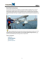
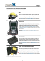


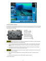

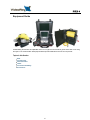


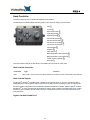
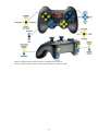
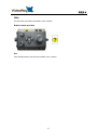
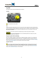


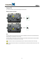
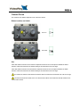
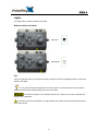
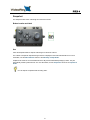
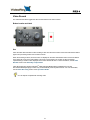
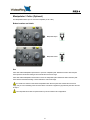


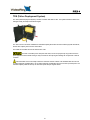
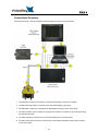


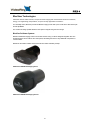
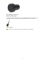

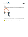
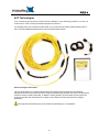
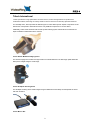


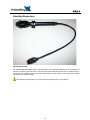

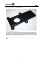
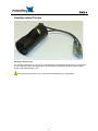
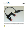
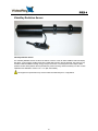
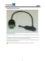


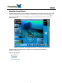
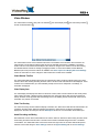

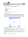
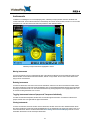
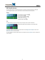
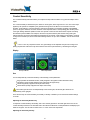

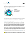
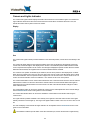
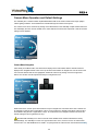

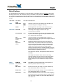


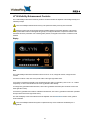
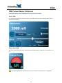


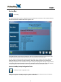


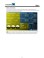


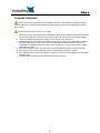

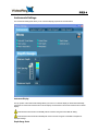

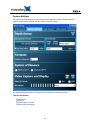
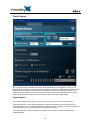
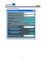
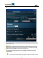

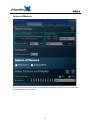
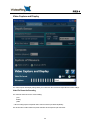
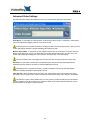
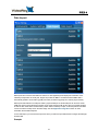

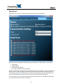


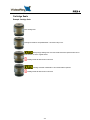


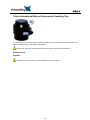


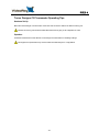


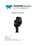


![RessqM, Enhanced Version of RESSQ [Javandel et al., 1984]](http://vs1.manualzilla.com/store/data/005674408_1-e8a4b9f66c80cdc83d847a710e5b4b1f-150x150.png)