1
INSTALLATION AND USER GUIDE FOR
GASSONIC OBSERVER-H
ULTRASONIC GAS LEAK DETECTOR
This page intentionally left blank.
INSTALLATION AND USER GUIDE FOR
GASSONIC OBSERVER-H
ULTRASONIC GAS LEAK DETECTOR
Installation and User Guide for Gassonic Observer-H (MANOBSERVER-H, Rev C/3-12)
Page 1
This page intentionally left blank.
Installation and User Guide for Gassonic Observer-H (MANOBSERVER-H, Rev C/3-12)
Page 2
Table of Contents
1.0 TECHNICAL DATA ON THE GASSONIC OBSERVER-H ........................................................................... 6 2.0 INTRODUCTION ........................................................................................................................................ 7 3.0 GENERAL DESCRIPTION AND FEATURES ............................................................................................. 7 3.1 AREA MONITORED BY THE GASSONIC OBSERVER-H ..............................................................................8 3.2 DETECTOR OUTPUTS .....................................................................................................................................9 4.0 INSTALLATION ......................................................................................................................................... 9 4.1 MECHANICAL CONSTRUCTION ....................................................................................................................9 4.2 MECHANICAL OPERATION AND SAFETY ................................................................................................. 11 4.2.1 SPECIFIC CONDITIONS OF USE ................................................................................................................. 11 4.3 MOUNTING 11 4.4 WIRING DIAGRAM ...................................................................................................................................... 12 4.5 PROTECTIVE EARTH GROUNDING ............................................................................................................ 12 5.0 OPERATION AND SETUP ....................................................................................................................... 13 5.1 RECEIPT OF EQUIPMENT ........................................................................................................................... 13 5.2 NORMAL OPERATION ................................................................................................................................ 13 5.3 SETUP
13 5.3.1 TRIGGER LEVEL........................................................................................................................................... 14 5.3.2 TIME DELAY 14 5.3.3 ALARM RELAY ENERGIZED/DE-ENERGIZED .......................................................................................... 14 5.3.4 ALARM RELAY LATCH/NON-LATCHED .................................................................................................... 14 5.3.5 MODBUS
14 5.3.6 HART ENABLE ............................................................................................................................................. 14 5.3.7 HAZARDWATCH .......................................................................................................................................... 14 5.4 ACOUSTIC SELF-TEST ................................................................................................................................. 15 5.5 INPUTS
15 5.6 OUTPUT METHODS ..................................................................................................................................... 15 5.6.1 RELAY RATINGS.......................................................................................................................................... 16 5.6.2 ALARM RELAY OUTPUT ............................................................................................................................. 16 5.6.3 4-20MA OUTPUT ......................................................................................................................................... 16 5.6.4 ERROR / FAULT OUTPUT ........................................................................................................................... 17 5.7 USER DISPLAY & MAGNET INTERFACE................................................................................................... 20 5.7.1 FORCED ACOUSTIC TEST ........................................................................................................................... 22 5.7.2 SETTING / CHECKING TRIGGER LEVEL ................................................................................................... 22 5.7.3 SETTING / CHECKING DELAY TIME .......................................................................................................... 23 5.7.4 SETTING / CHECKING ALARM RELAY ENERGIZED / DE-ENERGIZED ................................................. 24 5.7.5 SETTING / CHECKING ALARM LATCHING ON / OFF .............................................................................. 25 5.7.6 SETTING / CHECKING FACTORY DEFAULT ON / OFF ............................................................................ 26 5.7.7 SWITCHING HAZARDWATCH MODE ON/OFF ......................................................................................... 27 5.7.8 HART ON/OFF ............................................................................................................................................. 28 5.7.9 MODBUS SETTING: BAUD (CHANNEL ONE): ........................................................................................... 29 5.7.10 MODBUS SETTING: FORMAT (CHANNEL ONE): ...................................................................................... 30 5.7.11 MODBUS SETTING: ADDRESS (CHANNEL ONE): .................................................................................... 31 5.7.12 BAUD (CHANNEL TWO): ............................................................................................................................. 33 5.7.13 FORMAT (CHANNEL TWO): ........................................................................................................................ 33 5.7.14 ADDRESS (CHANNEL TWO):...................................................................................................................... 34 Installation and User Guide for Gassonic Observer-H (MANOBSERVER-H, Rev C/3-12)
Page 3
6.0 GAIN TEST AND CALIBRATION ............................................................................................................. 35 6.1 GAIN TEST 35 6.2 CALIBRATION .............................................................................................................................................. 35 7.0 MODBUS DIGITAL INTERFACE ............................................................................................................. 37 7.1 BAUD RATE 37 7.2 DATA FORMAT ............................................................................................................................................ 37 7.3 MODBUS READ STATUS PROTOCOL (QUERY/RESPONSE) .................................................................. 37 7.3.1 MODBUS READ QUERY MESSAGE ........................................................................................................... 37 7.3.2 MODBUS READ RESPONSE MESSAGE.................................................................................................... 38 7.4 MODBUS WRITE COMMAND PROTOCOL (QUERY/RESPONSE) .......................................................... 38 7.4.1 MODBUS WRITE QUERY MESSAGE ......................................................................................................... 38 7.4.2 MODBUS WRITE RESPONSE MESSAGE .................................................................................................. 39 7.4.3 FUNCTION CODES SUPPORTED................................................................................................................ 39 7.5 EXCEPTION RESPONSES AND EXCEPTION CODES ............................................................................... 39 7.5.1 EXCEPTION RESPONSES ........................................................................................................................... 40 7.5.2 EXCEPTION CODE FIELD ............................................................................................................................ 40 7.6 COMMAND REGISTER LOCATIONS .......................................................................................................... 40 7.6.1 OPERATIONAL MODE COMMANDS.......................................................................................................... 40 7.7 OBSERVER-H COMMAND REGISTER DETAILS ....................................................................................... 45 7.7.1 ANALOG (00H) ............................................................................................................................................ 45 7.7.2 MODE (01H) 45 7.7.3 PRIMARY FAULT STATUS/ERROR 1 (02H) ............................................................................................. 46 7.7.4 FAULT STATUS/ERROR 2 (03H) ............................................................................................................... 47 7.7.5 MODEL TYPE (04H) .................................................................................................................................... 47 7.7.6 SOFTWARE REVISION MAJOR (05H) ....................................................................................................... 47 7.7.7 DB LEVEL (06H) .......................................................................................................................................... 48 7.7.8 PEAK SOUND (07H) .................................................................................................................................... 48 7.7.9 UNIT TEMPERATURE (08H) ....................................................................................................................... 48 7.7.10 MODBUS DISPLAY (09H, 0AH) ................................................................................................................. 48 7.7.11 SERIAL NUMBER (0BH, 0CH) .................................................................................................................... 48 7.7.12 TRIGGER LEVEL (0DH) ............................................................................................................................... 48 7.7.13 TRIGGER DELAY (0EH) ............................................................................................................................... 48 7.7.14 COMM 1 ADDRESS (0FH) .......................................................................................................................... 48 7.7.15 COMM 1 BAUD RATE (10H) ...................................................................................................................... 49 7.7.16 COMM 1 DATA FORMAT (11H) ................................................................................................................. 49 7.7.17 COMM 2 ADDRESS (12H).......................................................................................................................... 49 7.7.18 COMM 2 BAUD RATE (13H) ...................................................................................................................... 50 7.7.19 COMM 2 DATA FORMAT (14H) ................................................................................................................. 50 7.7.20 SOFTWARE REV MINOR (15H) ................................................................................................................. 50 7.7.21 RESET ALARM (16H) .................................................................................................................................. 50 7.7.22 SUB MODE (17H) ........................................................................................................................................ 51 7.7.23 ACOUSTIC TEST (18H) ................................................................................................................................ 51 7.7.24 HAZARDWATCH (19H) ............................................................................................................................... 51 7.7.25 RELAY STATE (1AH) ................................................................................................................................... 52 7.7.26 ALARM LATCH (1BH).................................................................................................................................. 52 7.7.27 RELAY ENERGIZE (1CH)............................................................................................................................. 52 7.7.28 HART ENABLE (1DH) .................................................................................................................................. 52 7.7.29 HART TEST (1EH) ........................................................................................................................................ 52 7.7.30 CAL ABORT (1FH) ....................................................................................................................................... 53 7.7.31 COMM 1 TOTAL ILLEGAL NUMBER OF REGISTERS ERRORS (20H) ................................................... 53 7.7.32 COMM 1 BUS ACTIVITY RATE % (21H) .................................................................................................... 53 7.7.33 COMM 1 FUNCTION CODE ERRORS (22H) ............................................................................................. 53 7.7.34 COMM 1 STARTING ADDRESS ERRORS (23H) ...................................................................................... 53 Installation and User Guide for Gassonic Observer-H (MANOBSERVER-H, Rev C/3-12)
Page 4
7.7.35 7.7.36 7.7.37 7.7.38 7.7.39 7.7.40 7.7.41 7.7.42 7.7.43 7.7.44 7.7.45 7.7.46 7.7.47 7.7.48 7.7.49 7.7.50 7.7.51 7.7.52 7.7.53 7.7.54 7.7.55 7.7.56 7.7.57 7.7.58 7.7.59 7.7.60 7.7.61 7.7.62 COMM 1 TOTAL RECEIVE ERRORS (24H) ............................................................................................... 53 RXD CRC ERRORS (25H) ........................................................................................................................... 53 RXD CRC ERRORS (SAME AS 25H) (26H) .............................................................................................. 53 COMM 1 PARITY ERRORS (27H) .............................................................................................................. 53 COMM 1 OVERRUN ERRORS (28H) ......................................................................................................... 53 COMM 1 FRAMING ERRORS (29H) .......................................................................................................... 53 COMM 1 TOTAL UART RECEIVE ERRORS (2AH) .................................................................................... 54 FACTORY DEFAULT (2BH) ......................................................................................................................... 54 COMM 1 CLEAR ERROR (2CH) ................................................................................................................. 54 CLEAR STATS 1(2D) ................................................................................................................................... 54 HART CURRENT (2E) .................................................................................................................................. 54 HART PRESENT (2F) ................................................................................................................................... 54 EVENT LOGGING (30H – 5FH)................................................................................................................... 54 USER DATA (60H – 6F) .............................................................................................................................. 62 COMM 2 BUS ACTIVITY RATE % (71H) .................................................................................................... 62 COMM 2 FUNCTION CODE ERRORS (72H) ............................................................................................. 62 COMM 2 STARTING ADDRESS ERRORS (73H) ...................................................................................... 62 COMM 2 TOTAL RECEIVE ERRORS (74H) ............................................................................................... 62 RXD CRC ERRORS HI (75H) ...................................................................................................................... 62 RXD CRC ERRORS LO (SAME AS HI) (76EH) .......................................................................................... 62 COMM 2 PARITY ERRORS (77H) .............................................................................................................. 62 COMM 2 OVERRUN ERRORS (78H) ......................................................................................................... 62 COMM 2 FRAMING ERRORS (79H) .......................................................................................................... 63 COMM 2 TOTAL RECEIVE ERRORS (7AH) ............................................................................................... 63 MODBUS CAL ERROR (7BH) ..................................................................................................................... 63 CLEAR COMM 2 UART ERRORS (7CH) .................................................................................................... 63 CLEAR COMM 2 MODBUS ERRORS (7DH) ............................................................................................. 63 INPUT VOLTAGE (8DH) ............................................................................................................................... 63 8.0 CUSTOMER SUPPORT ........................................................................................................................... 64 8.1 GENERAL MONITORS’ OFFICES................................................................................................................ 64 9.0 APPENDIX............................................................................................................................................... 65 9.1 WARRANTY 65 9.2 SPECIFICATIONS ......................................................................................................................................... 65 9.2.1 ELECTRICAL SPECIFICATIONS .................................................................................................................. 65 9.2.2 APPROVALS 67 9.3 SPARE PARTS AND ACCESSORIES.......................................................................................................... 67 9.3.1 INSTALLATION DRAWINGS ....................................................................................................................... 67 9.3.2 CALIBRATION EQUIPMENT ........................................................................................................................ 67 9.3.3 SPARE PARTS ............................................................................................................................................. 67 9.3.4 MICROPHONE REPLACEMENT:................................................................................................................. 68 9.3.5 SOUND SOURCE ASSEMBLY REPLACEMENT ......................................................................................... 68 Installation and User Guide for Gassonic Observer-H (MANOBSERVER-H, Rev C/3-12)
Page 5
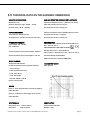
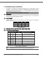
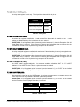
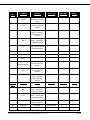
1.0 TECHNICAL DATA ON THE GASSONIC OBSERVER-H
ACOUSTIC SPECIFICATIONS
GAS LEAK DETECTION COVERAGE (REF = METHANE)
Microphone unit:
Ultrasonic background noise < 74 dB (low nose areas)
Detector frequency range: 25kHZ – 70 kHz
12m radius @ leak rate = 0.1 kg/sec
Dynamic range: 58 db – 104 dB
8m radius @ leak rate = 0.03 kg/sec
TEST SOUND SOURCE
Ultrasonic background noise <84 dB (high noise areas)
Test frequency: 40 kHz ± 3 kHz
8m radius @ leak rate = 0.1 kg/sec
Sound Pressure: 100 dB, 68 mm from the sound
4m radius @ leak rate = 0.03 kg/sec
POWER REQUIREMENTS
Input voltage: 15 – 36 VDC
Um = 250 Vrms
CERTIFICATIONS
ATEX/IECEx: Ex d ia IIB+H2 T6 Gb, Ex tb IIIC T85°C Db
(Ta = -40°C to +60°C)
FM 11ATEX0003X IECEx FMG 11.0003X
II 2 G D
15 volts maximum current consumption: 250 mA
FM/CSA: Class I, Div. 1, 2 Groups B.C.D
Class II/III Div. 1, 2 Groups E,F,G (Ta = -40°C to +60°C)
24 volt maximum current consumption: 170 mA
Functional Safety per IEC 61508
HART Protocol Rev 6, Emerson AMS Aware
OUTPUT CURRENT
Analog 4-20 mA interface
INGRESS PROTECTION
(maximum permitted load resistance is 600 Ω)
IP66, Type 4X
0 mA: Start up
1 mA: Pulsed Acoustic error
0 mA: Other Errors
3 mA: Unit inhibit
4-20 mA: 58 dB – 104 dB
Source or Sink output
RELAYS
Relay 1 – Error/fault indication (normally energized):
8 A @ 250 VAC
Relay 2 – Indication of alarm trigger level reached.
8 A @ 250 VAC
INPUT SIGNALS
Alarm relay reset
Alarm test
CONSTRUCTION
Open or ground
Open or ground
Stainless steel AISI 316L
Weight: 7.5 kg
Installation and User Guide for Gassonic Observer-H (MANOBSERVER-H, Rev A/09-11)
Page 6
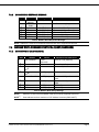
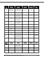
LED OUTPUT
DIMENSIONS
On for alarm
Diameter: 203mm
Width: 203mm
SERIAL DIGITAL COMMUNICATION
Height: 201mm
Dual Modbus or Single Modbus and HART
HART Input Impedance
Source C 1.2 nf 177 K
RF EMISSIONS AND IMMUNITY
Sink
Tested according to: EN 61000-6-2, EN 61000-6-4
C 4.0 nf 178 K
ENVIRONMENTAL DATA
Operational temperature range: -40°C to 60°C
Humidity: 0 to 95% non condensing
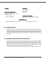
2.0 INTRODUCTION
The Gassonic Observer-H is an ultrasonic gas leak detector for detecting pressurized gas leaks. The
Observer-H utilizes advanced acoustic technology to detect gas leaks and incorporates a patented
Senssonic self-test system for failsafe operation. Industry standard output and communications options
are included in the Observer-H to provide flexible integration in a broad range of applications. This user
manual describes the installation, operation, and maintenance of the Observer-H to ensure optimal
performance.
3.0 GENERAL DESCRIPTION AND FEATURES
The Gassonic Observer-H detects leaks from pressurized gas systems by sensing the airborne
ultrasound produced by the gas escaping. This detection method is omni-directional. It can function in
extreme weather conditions and is ideal for monitoring leaks from valves and flanges in complex
pipeline systems, both onshore and offshore. The detector has the following certifications: ATEX,
IECEx, FM, CSA, HART, and IEC 61508. The detector housing is casted AISI 316L, acid-proof
stainless steel and the ingress protection is IP66 with a NEMA rating of Type 4X.
The performance of the Gassonic Observer-H as a safety device is not covered by the ATEX certificate.
Installation and User Guide for Gassonic Observer-H (MANOBSERVER-H, Rev C/3-12)
Page 7
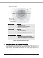
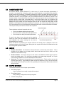
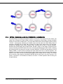
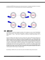
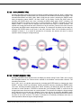
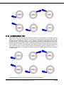
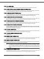
HIGH-NOISE AREAS
Typical areas:
- Turbo compressor areas
- Complete open offshore weather deck
- Next to very noisy machinery
LOW-NOISE AREAS
Typical areas:
- Areas with no machinery
- Areas with low frequency machine made noise
VERY LOW-NOISE AREAS
Typical areas:
- Onshore wellhead areas in calm environment
- Salt dome gas storage facilities in calm environment
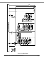
Figure 1: Detector Coverage Characteristics
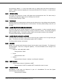
3.1
AREA MONITORED BY THE GASSONIC OBSERVER-H
The detection coverage of the Gassonic Observer-H is determined by the ultrasonic noise levels in the
area of installation. Experience has shown that most process environments can be divided into three
overall noise levels. This is illustrated in the image above. The detection coverage characteristics are
based on live tests and show the minimum coverage of the Gassonic Observer-H detector in areas
without solid physical obstructions between the detector and the leak. For further instructions on
installation, Gassonic A/S can be consulted.
Installation and User Guide for Gassonic Observer-H (MANOBSERVER-H, Rev C/3-12)
Page 8
3.2
DETECTOR OUTPUTS
The Gassonic Observer-H detector has several output methods:
Analog 4–20 mA interface - Sink or Source (Factory setting = Source)*
Digital outputs are Modbus or optional HART.
Modbus provides control information in a RS485 physical layer and a Modbus protocol.
HART (optional) is digital information over the analog output. Thus, a user can use an existing
three wire cable and obtain control information without rewiring.
One Modbus is always present. The second Modbus is also present but maybe overridden by
an optional HART.
Alarm relay
The Alarm relay is controlled by an adjustable trigger level in 5 dB steps, from 59 to 99 dB and
has an adjustable internal alarm delay from 0 to 600 seconds. It is necessary to introduce an
alarm delay of at least 10 seconds either internally or in the control system. (Factory setting 79 dB and 10 seconds delay)
Error relay
The error relay is normally energized and de-energized for error
* Sink - The detector receives a current loop. Source - The detector sends out a current loop.
4.0 INSTALLATION
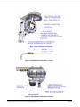
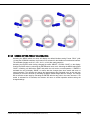
4.1
MECHANICAL CONSTRUCTION
The Gassonic Observer-H consists of two chambers. Both chambers are certified as flameproof (Ex d)
and Explosionproof (XP). The cables are connected through M20 x 1.5 6H cable entries in the top
chamber using approved Ex d glands or approved conduit with seal installed within 18” of the detector.
The inner cores of the cable penetrating the detector should be at least 25 cm long. This will ensure no
tension on the wires and connector PCB when the top chamber is opened. The two mounting bolts are
on the top chamber of the detector and this means that the cables will enter on the fixed part of the
detector. The bottom part is attached to the top by means of six Allen screws with lock washers.
Unscrewing these screws will expose the connector PCB in the top chamber. These screws will be
fixed by retaining washers to the bottom part. The bottom part of the detector is supported by the Loadstrap, which is connected to the top.
The bottom chamber contains integral associated intrinsically safe apparatus limiting energy to an
intrinsically safe microphone and piezo source, mounted to the exterior of the enclosure.
Installation and User Guide for Gassonic Observer-H (MANOBSERVER-H, Rev C/3-12)
Page 9
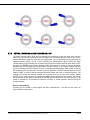
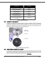
Figure 2: Mechanical Construction – Internal
Figure 3: Mechanical Construction – External
Installation and User Guide for Gassonic Observer-H (MANOBSERVER-H, Rev C/3-12)
Page 10
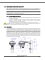
4.2 MECHANICAL OPERATION AND SAFETY
When closing the top chamber ensure that the Load-strap and wires are not caught between the
bulkhead and the top part of the detector. Check the status of the O-ring and the flame path. Replace
the O-ring if damaged. Send the unit to GM Service Repair for repair if the flame path is damaged.
NOTE: The ambient temperature is limited to -40ºC to +60ºC. The performance of the Gassonic
Observer-H Ultrasonic Gas Leak Detector, as a safety device per clause 1.5 of Annex II of the ATEX
Directive 94/9/EC, is not covered by this certificate.
4.2.1 SPECIFIC CONDITIONS OF USE
The Class A2-70 M6x1x20 screws connecting the bulkhead flange joints must be tightened to 9
Nm using a torque wrench.
For Division 1 installations, the piezo source contains aluminum and is considered to present a
potential risk of ignition by impact or friction. Care must be taken into account during
installations and use to prevent impact or friction.
Consult the manufacturer if dimensional information on the flameproof joints is necessary.
WARNING: The inner six screws should not be unscrewed and the bottom chamber should not be
opened. The warranty will be void if the bottom chamber is opened.
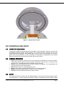
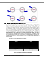
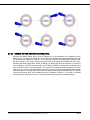
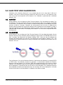
4.3 MOUNTING
Two M8 stainless steel bolts (not supplied), 88mm apart, attached to the top of the detector are used to
fix the Gassonic Observer-H in its operating position. These bolts may penetrate the detector top by a
maximum of 14 mm. The detector can be mounted to a freestanding pole or wall, using the Gassonic
mounting bracket 80601-1. This bracket is an optional accessory and is supplied with two M8 mounting
U-bolts which can fit around a pole with a maximum dimension of 63 mm. It is possible to mount the
detector directly onto non-vibrating structural beams or cable-trays. The microphone should face
downwards and if tilting of the detector is necessary, the angle of incline should not exceed 45°. Avoid
when mounting the detector within a half meter from a solid structure for example a wall or a big vessel,
to point the acoustic test sound source into the direction of this structure. The sound source should be
pointing into free space as far as possible.
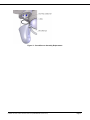
Figure 4: Mounting Diagram
Installation and User Guide for Gassonic Observer-H (MANOBSERVER-H, Rev C/3-12)
Page 11
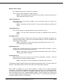
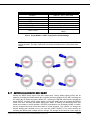
4.4 WIRING DIAGRAM
Figure 5: Wiring Diagram
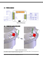
4.5 PROTECTIVE EARTH GROUNDING
Figure 6: External Earth Terminal
The protective earth ground terminal requires the use of an M5 ring lug and star washer. The wire gauge should
be less than or equal to the gauge of the power supply wires.
Installation and User Guide for Gassonic Observer-H (MANOBSERVER-H, Rev C/3-12)
Page 12
Figure 7: Internal Earth Terminal
5.0 OPERATION AND SETUP
5.1 RECEIPT OF EQUIPMENT
All equipment shipped by General Monitors is packaged in shock absorbing containers, which provide
considerable protection against physical damage. The contents should be carefully removed and
checked against the packing list. If any damage has occurred or there is any discrepancy in the order,
please notify General Monitors as soon as possible. All subsequent correspondence with General
Monitors must specify the equipment part number and the serial number.
5.2 NORMAL OPERATION
Power up of the Gassonic Observer-H The unit will perform an initialization of the micro-controller,
internal tests and then goes into normal operation mode within a few seconds. The output current
will be 0.0 mA. The display will show the software revision and “test”
Normal The real-time ultrasonic sound level will be shown on the display. The corresponding 4-20
mA value will be set on the analog output.
Alarm The Alarm relay is a single pole double throw.
Error The Error relay is a single pole double throw. It is normally energized.
Modbus The Modbus digital interface is ready to receive a command.
Self Test The acoustic Self-test is done at regular intervals.
5.3 SETUP
The setup can be done in three ways. The display/magnet is a user input that only requires a magnet
as an external tool. It is best used in simple systems. HART is a method that requires a HART modem
Installation and User Guide for Gassonic Observer-H (MANOBSERVER-H, Rev C/3-12)
Page 13
and supporting software. It is best used where there is existing wiring and control information is
desired. Modbus requires a separate pair of wires and a RS-485 to PLC converter. It is best used for
large systems.
5.3.1
TRIGGER LEVEL
The trigger level should be at least 6 dB higher than the background noise. The Alarm relay is
controlled by an adjustable trigger level in 5 dB steps, from 59 to 99.
The factory default setting is 79 dB.
5.3.2
TIME DELAY
An alarm delay time is implemented to eliminate spurious alarms due to short background noise peaks.
This delay time can be set internally from 0 to 600 seconds. The factory default setting is set to 01 (10
seconds).
5.3.3
ALARM RELAY ENERGIZED/DE-ENERGIZED
The alarm relay can be normally energized or normally de-energized. In either energized state the
single pole double throw allows for opening or closing a contact for an alarm. The normally energized
state is a failsafe method. If an alarm or power outage occurs an alarm condition will be indicated.
The factory default setting is normally de-energized.
5.3.4
ALARM RELAY LATCH/NON-LATCHED
The alarm relay can be latched. This is used to retain the alarm condition even if the gas leak goes
away. The relay can be reset via the display magnets, HART or Modbus.
The factory default setting is non-latched.
5.3.5
MODBUS
Modbus is an optional serial information channel used to obtain control information. The Observer-H
has dual Modbus. Each one is configured separately. The second Modbus can be changed to an
optional HART.
Baud rate 2400, 4800, 9600, 19200
Factory default is 19200
Format
Factory default is 8-N-1
Address
Factory default is Channel 1 Address 1 and Channel 2 Address 2
5.3.6
HART ENABLE
Selects whether channel 2 is Modbus or HART
Factory default is if HART is installed HART is enabled & current is normal.
5.3.7
HAZARDWATCH
HazardWatch is used when the Observer-H is part of a HazardWatch Fire and Gas System
manufactured by General Monitors.
Factory default is disabled
Installation and User Guide for Gassonic Observer-H (MANOBSERVER-H, Rev C/3-12)
Page 14
5.4 ACOUSTIC SELF-TEST
An acoustic self-test (named Senssonic™) is done every 15 minutes and takes approximately 8
seconds. A test signal with a frequency sweep at constant amplitude is transmitted by the ultrasonic
sound source to the microphone. The detector analyzes the result of the sweep and stores the highest
dB value. This value is compared to a factory reference value and the result must be within a
predefined tolerance. If the test signal is out of the predefined tolerance, the Observer-H will do a new
acoustic self-test 30 seconds after the first failed test. If this test signal is still out of tolerance a new
acoustic self-test is done again 30 seconds later. If the third test signal is still out of tolerance, the
Gassonic Observer-H will go into acoustic error mode. In acoustic error mode the code “ERAC” will be
displayed, the Error Relay will be de-energized, and the user can acquire the relay status via the
Modbus or HART digital communication interfaces. Furthermore, the 4-20 mA output will indicate 1 mA
for 5 seconds and return to normal ultrasonic background noise level until the next acoustic test failure.
This sequence will repeat until the acoustic fault is repaired.
There could be a number of causes for this error:
There is an obstacle blocking the sound path.
The sound source is faulty and needs replacement.
The microphone is faulty and needs replacement.
If none of the above is true, the unit can be tested by
means of a ”Gain Test” with a Gassonic 1701 Portable Test
and Calibration Unit, before sending the unit back to
General Monitors for service.
When the detector is performing the Acoustic Self-test the last dB level is displayed on the user
interface and sent to the 4-20 mA output. During this time a green LED will be illuminated and can be
seen through the optical link window.
5.5 INPUTS
Remote Alarm Reset: The Observer-H has provisions for a remote relay reset switch. This is
provided so the operator has a handy remote switch and does not have to climb up to the
Observer-H and reset the relays.
Restore Defaults: The remote reset pin is also used to reset Modbus address trigger levels etc
back to the default values. This is done by grounding the pin and turning the power on. The pin
must remain grounded for one minute after the power is turned on.
Alarm test: The Observer-H has provisions for a remote alarm test. This is useful to test out the
external system wiring. By grounding the alarm test pin the Observer-H will go to alarm and stay
there until the alarm test pin is removed. If the grounding time is longer than 30 seconds, the device
will go into fault.
5.6 OUTPUT METHODS
The Gassonic Observer-H has 4 major output methods:
Alarm Relay Output.
Can be configured as normally energized/de-energized
Errors Relay Output.
Relay is always configured as normally energized.
4-20 mA Analog Output.
Installation and User Guide for Gassonic Observer-H (MANOBSERVER-H, Rev C/3-12)
Page 15
Can be configured as source or sink
Serial Digital Communication.
Configurable as Dual Modbus or Single Modbus and HART (optional)
The users need to determine the output method suited for their use.
5.6.1
RELAY RATINGS
8 A @ 250 VAC
See graph in section 1.0 for DC ratings
5.6.2
ALARM RELAY OUTPUT
When using this method, an internal trigger level and delay time must be set. The trigger level should
be at least 6 dB higher than the background noise. The trigger level can be set in steps of 5 dB from 59
dB to 99 dB and the factory setting is 79 dB. An alarm delay time is implemented to eliminate spurious
alarms due to short background noise peaks. This delay time can be set internally from 0 to 600
seconds. The factory setting is set to 01 (10 seconds). The delay can alternatively be set in the ”Fire
and Gas Panel”.
When a gas leak occurs in the detector’s coverage area, the trigger level will be reached, the LED in
optical link window will be illuminated and the alarm relay timer will be started. When the delay times
out, the unit will go into alarm mode, which will result in the following:
•
•
•
5.6.3
The dB value preceded by an “A” will flash on the display.
The alarm relay will activate.
An event will be recorded.
4-20MA OUTPUT
The 4-20 mA output is factory and field configurable to either Source or Sink current. At normal
operation the output will be between 4 and 20 mA. When using this output method, a trigger level at
least 6 dB higher than the background noise and an alarm delay time > 10 seconds should be set in the
fire & gas system.
The output value in mA corresponding to the sound pressure in dB can be calculated by the following
formula:
{[(n – 58) * 16] / 46} + 4 = x
The transposed formula:
{[(x – 4) * 46] / 16} + 58 = n
n: Sound Level in dB
x: Output value in mA
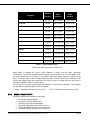
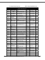
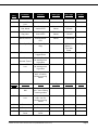
The 0 to 20 mA output is a current signal that corresponds to the following signals:
Condition
START UP
FAULT
ACOUSTIC ERROR
Modbus
(Current )
HART
(Normal)
HART
(Special)
0 mA
3.5 ± 0.2 mA
1.25 ± 0.2 mA
0 mA
3.5 ± 0.2 mA
1.25 ± 0.2 mA
1.0* mA
3.5* ± 0.2 mA
1.25* ± 0.2 mA
Installation and User Guide for Gassonic Observer-H (MANOBSERVER-H, Rev C/3-12)
Page 16
Condition
OFFLINE
Modbus
(Current )
HART
(Normal)
HART
(Special)
3.0 mA
3.5 ± 0.2 mA
3.0 ± 0.2 mA
4.0 mA
4.0 ± 0.2 mA
4.0 ± 0.2 mA
4.3 mA
4.3 ± 0.2 mA
4.3 ± 0.2 mA
6.1 mA
6.1 ± 0.2 mA
6.1 ± 0.2 mA
7.8 mA
7.8 ± 0.2 mA
7.8 ± 0.2 mA
9.6 mA
9.6 ± 0.2 mA
9.6 ± 0.2 mA
11.3 mA
11.3 ± 0.2 mA
11.3 ± 0.2 mA
13.0 mA
13.0 ± 0.2 mA
13.0 ± 0.2 mA
14.8 mA
14.8 ± 0.2 mA
14.8 ± 0.2 mA
16.5 mA
16.5 ± 0.2 mA
16.5 ± 0.2 mA
18.3 mA
18.3 ± 0.2 mA
18.3 ± 0.2 mA
20.0 mA
20.0 ± 0.2 mA
20.0 ± 0.2 mA
≤ 58 DB
59 DB
64 DB
69 DB
74 DB
79 DB
84 DB
89 DB
94 DB
99 DB
≥ 104 DB
Table 1: Analog Output Levels
* See acoustic self-test sequence in Section 5.4.
When HART is selected, the output current changes to comply with the HART Foundation
requirements. The HART Foundation does not specify current below 3.5 mA. In normal HART mode,
the actual current does not go below 3.5 mA. Modbus reports the analog output as if HART was not
there,. This allows users to use a constant Modbus program. When the alarm relay is latched but, the
current and display follows the present DB. The relay will return to normal after the relay reset is
activated via Modbus, HART, or remote switch.
The unit will have an Inhibit output when Setup, Calibrate, or acoustic test is activated. This activation
can take place via display magnets, HART, or Modbus.
1 Source
5.6.4
- The detector sends out a current loop.
2 Sink
- The detector receives a current loop.
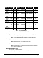
ERROR / FAULT OUTPUT
Error/fault conditions are indicated in many ways:
On the User Interface display.
Through the 4-20 mA analog output.
The Error/ Fault relay will de-energize.
The HART digital information will show an error.
The Modbus digital information will show an error.
A fault event will be recorded every 30 seconds.
Installation and User Guide for Gassonic Observer-H (MANOBSERVER-H, Rev C/3-12)
Page 17
Display
AO
Modbus
Error relay
Low supply
ERV-
0 mA*
0 mA
De-energized
ERAC
1 mA
**
0 mA
De-energized
EAST
0 mA*
0 mA
De-energized
Check switch wiring
Yes
ERST
0 mA*
0 mA
De-energized
Check switch wiring
Yes
EMAG
0 mA*
0 mA
De-energized
Remove magnet
Yes
EINV
0 mA*
0 mA
De-energized
Return to factory
No
ECRT
0 mA*
0 mA
De-energized
Return to factory
No
EUSR
0 mA*
0 mA
De-energized
HART
memory error
EHRT
0 mA*
0 mA
De-energized
Event
memory error
EEVT
0 mA*
0 mA
De-energized
Acoustic
Error
Remote
alarm switch
stuck
Remote relay
reset switch
stuck
Magnetic
sensors
stuck
Internal
voltage error
Critical
memory error
User memory
error
User action
Gas
overrides
Error / Fault
Restore proper
operating voltage
Check sound path from
piezo to microphone
Recycle power and
restore user defaults.
Recycle power and
restore HART
information.
Recycle power event
data maybe accurate.
Yes
Yes
No
No
No
Table 2: Error / Fault Indications
* See acoustic self-test sequence in Section 5.4. ** See HART output current in Table 2.
Low Supply
This fault occurs if the supply voltage at the Observer-H drops below +12.5 VDC.
supply returns to normal the Observer-H will go back to start up.
When the
Action - Ensure that the supply voltage is at least +14 VDC at the Observer-H.
Acoustic Error
The Observer-H has failed the acoustic test.
Action - Make sure the foam and all acoustic parts are clean.
Remote Alarm Switch Stuck
The “remote alarm” is closed for 60 Seconds.
Action - Check the wiring on the remote alarm. Once the short circuit is cleared, the
unit will return to normal operation.
Remote Relay Reset Switch Stuck
The “remote reset” is closed for 30 Seconds.
Action - Check the wiring on the remote reset switch. Once the short circuit is cleared,
the unit will return to normal operation.
Installation and User Guide for Gassonic Observer-H (MANOBSERVER-H, Rev C/3-12)
Page 18
Magnetic Sensors Stuck
The “magnetic sensor stuck” is closed for 60 Seconds.
One of the four magnet switches or a cable is shorted.
Action - If the magnetic switch is shorted, the unit must be returned to the factory or
authorized service center for service.
Internal Voltage Error
The possible errors are an internal voltage is not at the proper value or a circuit is not
functioning properly.
Action - An internal error has occurred. The unit must be returned to the factory for
service.
Critical Memory Error
This is a main memory error and the Observer-H may not function correctly.
Action – The unit must be returned to the factory or authorized service center for
repair.
User Memory Error
User memory includes the trigger level, delay time, latched /non-latched, energized/ nonenergized, Modbus setting, or any other user changeable settings. This error indicates one or
more of these values is wrong.
Action – Cycle power. The error will go away, but the data is still not correct. The
user must restore all user settings.
HART Memory Error
A HART memory register has an error. These registers contain HART user settings. This error
indicates one or more of these values are incorrect.
Action – Cycle power. The error will go away but the data is still not correct. The user
must restore all HART information.
Event Memory Error
Event memory has an error. Some or all of the event information is incorrect.
indicates one or more of these values are wrong.
This error
Action – Cycle power. The error will go away, but the data is still not correct.
The Observer-H has four different memory blocks that are periodically checked. The user is notified via
this Error / Fault Output function if an error occurs with any of these memory locations.
When HART is selected, the output current changes to comply with the HART Foundation
requirements. The HART Foundation does not specify current below 3.5 mA. In normal HART mode,
the actual current does not go below 3.5 mA. Modbus reports the analog output as if HART was not
there. This allows users to use a consistent Modbus program. When the alarm relay is latched, the
current and display follows the present dB. The relay will return to normal after the relay reset is
activated via Modbus, HART, or remote switch.
Installation and User Guide for Gassonic Observer-H (MANOBSERVER-H, Rev C/3-12)
Page 19
The unit will have an Inhibit output when Setup, Calibrate, or Acoustic Test Mode are activated. This
activation can take place via display magnets, HART, or Modbus.
5.7 USER DISPLAY & MAGNET INTERFACE
The User Interface consists of a four-digit LED display window and four magnetic switches to enable a
local operator to confirm or change settings without opening the unit. When the user interface is used
the Observer-H will change to setup mode. The setup mode consists of the following tests: Analog
Output=3.5mA (HART Enable), 3.0mA (HART Disable).
The Observer-H User Menu Diagram is captured on the following page.
Installation and User Guide for Gassonic Observer-H (MANOBSERVER-H, Rev C/3-12)
Page 20
Figure 8: User Menu Diagram
Installation and User Guide for Gassonic Observer-H (MANOBSERVER-H, Rev C/3-12)
Page 21
5.7.1
FORCED ACOUSTIC TEST
This will enable the local operator to test the acoustic properties of the unit. Activate the MENU switch
with the magnet-stick. The code “ATOF” (Acoustic Test Off) will be displayed. Activating the UP switch
(▲) will display the “wait” command followed by the sound level detected by the microphone emitted
from the sound source. If this value is flashing, the unit is failing the acoustic test. There could be a
number of causes for this error, see Section 5.3. for more information. The DOWN switch (▼) will stop
the acoustic test and display “ATOF”. Activating the ENTER switch at any time during this operation will
display “DONE” and take the unit back to Normal Operation. A maintenance event will be recorded. If
no switch is activated for 60 seconds the detector will return to normal operation.
5.7.2
SETTING / CHECKING TRIGGER LEVEL
The trigger level can be set from 59 to 99 dB in steps of 5 dB. The ALARM RELAY will activate at this
trigger level changing from open contact to closed (factory default). Activate the MENU switch twice
with the magnet-stick. The current trigger level will be displayed (factory setting = 79 dB). Activating the
UP switch (▲) will increment the trigger level by 5 dB. Activating the DOWN switch (▼) will decrement
the Trigger Level in 5 dB increments. Activating the ENTER switch without changes made, switches the
unit back to Normal Operation. Activating the ENTER switch with changes made, will flash “SAVE” on
the display. Confirm the save action by activating the ENTER switch once more. Activating the MENU
switch while “SAVE” is flashing, will discard the save and switch the unit back to Normal Operation. If
ENTER was activated the unit will display “DONE” to confirm that the changes have been saved and
return to Normal Operation.
The operator can change the trigger level and if desired move to the next item (delay time) in the menu
structure by activating the MENU switch straight after the change. The change will be saved at a later
stage by activating the ENTER switch at any point in the menu structure. If no switch is activated for 60
seconds the detector will return to normal operation without saving the changed settings.
Installation and User Guide for Gassonic Observer-H (MANOBSERVER-H, Rev C/3-12)
Page 22
5.7.3
SETTING / CHECKING DELAY TIME
The delay time is linked to the ALARM RELAY. The delay time can be set from 0 to 600 seconds. If the
relay output is being used for executive action, it is of utmost importance that the delay time is of a
sufficient length to eliminate spurious alarms. Activate the MENU switch three times with the magnetstick. The current delay time will be displayed (factory setting DT01 = 01 = 10 sec.). Activating the UP
switch (▲) will increment the delay time by 10 sec. Activating the DOWN switch (▼) will decrement the
delay time by 10 sec. Activating the ENTER switch without changes made, switches the unit back to
Normal Operation. Activating the ENTER switch with changes made, will flash “SAVE” on the display.
Confirm the save action by activating the ENTER switch once more. Activating the MENU switch while
“SAVE” is flashing, will discard the save and switch the unit back to Normal Operation. If ENTER was
activated the unit will display “DONE” to confirm that the changes have been saved and return to
Normal Operation. The operator can change the delay time and if desired move to the next item (alarm
relay energized/de-energized) in the menu structure by activating the MENU switch straight after the
change. The change will be saved at a later stage by activating the ENTER switch at any point in the
menu structure. If no switch is activated for 60 seconds the detector will return to normal operation
without saving the changed settings.
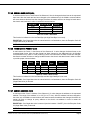
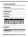
Display
Delay Time
DT00
0 Sec
DT01
10 Sec
DT02
20 Sec
DT03
30 Sec
….
….
DT 60
600 Sec
Table 3: Delay Time Settings
Installation and User Guide for Gassonic Observer-H (MANOBSERVER-H, Rev C/3-12)
Page 23
5.7.4
SETTING / CHECKING ALARM RELAY ENERGIZED / DE-ENERGIZED
The Alarm Relay is normally de-energized at power up of the unit. The output is an open contact. The
output can be changed to closed contact at alarm by energizing the Alarm Relay. Activate the MENU
switch four times with the magnet-stick. The current Alarm Relay status will be displayed (factory setting
= RLDE = de-energized). Activating the DOWN switch (▼) will switch the Alarm Relay status to
energized. Activating the UP switch (▲) will switch the Alarm Relay status back to de-energized.
Activating the ENTER switch without changes made, switches the unit back to Normal Operation.
Activating the ENTER switch with changes made, will flash “SAVE” on the display. Confirm the save
action by activating the ENTER switch once more. Activating the MENU switch while “SAVE” is flashing
will discard the save and switch the unit back to Normal Operation. If ENTER was activated the unit will
display “DONE” to confirm that the changes have been saved and return to Normal Operation. The
operator can change the relay energizing settings and if desired move to the next item (alarm latching
ON/OFF) in the menu structure by activating the MENU switch straight after the change. The change
will be saved at a later stage by activating the ENTER switch at any point in the menu structure. If no
switch is activated for 60 seconds the detector will return to normal operation without saving the
changed settings.
Installation and User Guide for Gassonic Observer-H (MANOBSERVER-H, Rev C/3-12)
Page 24
5.7.5
SETTING / CHECKING ALARM LATCHING ON / OFF
The Alarm Latching feature gives the local operator the opportunity to latch the alarm relay output in
alarm even if the sound level drops below the trigger level. The alarm latching is factory set to OFF.
Activate the MENU switch five times with the magnet-stick. The current Alarm Latching status will be
displayed (factory setting = ALOF = OFF). Activating the DOWN switch (▼) will switch the Alarm
Latching status to ON. Activating the UP switch (▲) will switch the Alarm Latching status back to OFF.
Activating the ENTER switch without changes made, switches the unit back to Normal Operation.
Activating the ENTER switch with changes made, will flash “SAVE” on the display. Confirm the save
action by activating the ENTER switch once more. Activating the MENU switch while “SAVE” is flashing
will discard the save and switch the unit back to Normal Operation. If ENTER was activated the unit will
display “DONE” to confirm that the changes have been saved and return to Normal Operation. The
operator can change the latching settings and if desired move to the next item (Factory Default
ON/OFF) in the menu structure by activating the MENU switch straight after the change. The change
will be saved at a later stage by activating the ENTER switch at any point in the menu structure. If no
switch is activated for 60 seconds the detector will return to normal operation without saving the
changed settings.
Reset a Latched Relay
Activating an UP, DOWN, or Enter magnet will reset a latched relay. The relay will not reset if an
alarm condition is still present.
Installation and User Guide for Gassonic Observer-H (MANOBSERVER-H, Rev C/3-12)
Page 25
5.7.6
SETTING / CHECKING FACTORY DEFAULT ON / OFF
The Factory Default command gives the local operator the opportunity to return all settings to factory
default. Activate the MENU switch six times with the magnet-stick. Factory Default OFF (FDOF) will be
displayed. Activating the DOWN switch (▼) will switch the Factory Default ON. Activating the UP switch
(▲) will switch the Factory Default OFF. Activating the ENTER switch without changing the status to
ON, switches the unit back to Normal Operation. Activating the ENTER switch having changed the
status to ON, will flash “SAVE” on the display. Confirm the save action by activating the ENTER switch
once more. Activating the MENU switch while “SAVE” is flashing will discard the save and switch the
unit back to Normal Operation. If ENTER was activated the unit will display “DONE” to confirm that all
settings have been returned to the Factory Default and return to Normal Operation. Activating the
MENU switch a 12th time will switch the unit to Normal Operation, if any changes were made in
previous menu items (HazardWatch Mode ON/OFF) the unit will flash “SAVE” on the display. Confirm
the save by activating the ENTER switch or discard the save by activating the MENU switch once more.
If no switch is activated for 60 seconds the detector will return to normal operation without saving the
changed settings.
The Observer-H factory default settings are as follows:
Feature
Modbus 1
Modbus 2
Trigger Level
Trigger Delay
Alarm Relay – Energized / De-Energized
Alarm Relay – Latched / Un-Latched
HART Enable
HART Current
Setting
Address 1, 8-N-1, 19200 baud
Address 1, 8-N-1, 19200 baud
79 dB
10 seconds
De-Energized
Un-Latched
(Disabled)
(Disabled)
Table 4: Dual Modbus Configuration Default Settings
Installation and User Guide for Gassonic Observer-H (MANOBSERVER-H, Rev C/3-12)
Page 26
Feature
Modbus 1
Modbus 2
Trigger Level
Trigger Delay
Alarm Relay – Energized / De-Energized
Alarm Relay – Latched / Un-Latched
HART Enable
HART Current
Setting
Address 1, 8-N-1, 19200 baud
(Disabled)
79 dB
10 seconds
De-Energized
Un-Latched
Enabled
3.5 mA for High Range; 1.25 mA for Low
Range
Table 5: Single Modbus + HART Configuration Default Settings
NOTE: There are three other ways to restore the default values. Both Modbus and HART can
send a command. The alarm reset switch can restore the default values. (See remote reset
switch).
5.7.7
SWITCHING HAZARDWATCH MODE ON/OFF
Activate the MENU switch seven times with magnet stick. Factory default setting (HZOF) will be
displayed. Activating the DOWN switch (▼) will switch the factory default ON (FD ON). Activating the
UP switch (▲) will switch the factory default OFF. Activating the ENTER switch having changed the
status ON/OFF, will flash “SAVE” on the display. Confirm the SAVE action by activating the ENTER
switch once more. Activating the MENU switch while “SAVE” is flashing, will discard the SAVE and
switch the unit back to normal operation. If ENTER is activated the unit will display “DONE” to confirm
that the changes have been saved and return to normal operation. The operator can change the
Hazard settings and if desired move to the next item (HART ON/OFF) in the menu structure by
activating the MENU switch straight after the change. The change will be saved at a later stage by
Installation and User Guide for Gassonic Observer-H (MANOBSERVER-H, Rev C/3-12)
Page 27
activating the ENTER switch at any point in the menu structure. If no switch is activated for 60 seconds,
the detector will return to normal operation without saving the changed settings.
5.7.8
HART ON/OFF
The Observer-H provides the operator the ability to field configure the unit to either Enable/Disable
HART communication. When HART communication is enabled, the Observer-H has the following:
Single Modbus + HART. When HART is disabled, the Observer-H supports Dual Modbus, but no
HART.
Activate the MENU switch eighth times with the magnet stick. Factory default setting (HTON) will be
displayed. Activating the UP switch (▲) will switch the factory Default OFF (). Activating DOWN switch
(▼) the will switch the factory default ON. Activating the ENTER switch having changed the status
ON/OFF, will flash “SAVE” on the display. Confirm the SAVE action by activating the ENTER switch
once more. Activating the MENU switch while “SAVE” is flashing, will discard the SAVE and switch the
unit back to normal operation. If ENTER is activated the unit will display “DONE” to confirm that the
changes have been saved and return to normal operation. The operator can change the HART setting
and if desired move to the next item (Baud Rate) in the menu structure by activating the MENU switch
straight after the change. The change will be saved at a later stage by activating the ENTER switch at
any point in the menu structure. If no switch is activated for 60 seconds, the detector will return to
normal operation without saving the changed settings.
By disabling the HART (HTOF), the channel two option of the Modbus setting will be accessed.
Installation and User Guide for Gassonic Observer-H (MANOBSERVER-H, Rev C/3-12)
Page 28
If HART is Enable (HTON): Activating the MENU twelve times will switch the unit to Normal Operation.
If HART is Disable (HTOF): Activating the MENU fifteen times will switch the unit to Normal Operation.
5.7.9
MODBUS SETTING: BAUD (CHANNEL ONE):
Activating the MENU switch nine times will display the default setting Baud rate “B192” (19200).Using
the UP/DOWN switches, the Baud Rate can be selected for the Modbus communication interface. The
selectable Baud Rates are 19200, 9600, 4800 or 2400 bits per second. Activating the ENTER switch
having changed the status ON/OFF, will flash “SAVE” on the display. Confirm the SAVE action by
activating the ENTER switch once more. Activating the MENU switch while “SAVE” is flashing, will
discard the SAVE and switch the unit back to normal operation. If ENTER is activated the unit will
display “DONE” to confirm that the changes have been saved and return to normal operation. The
operator can change the Baud rate and if desired move to the next item (Format) in the menu structure
by activating the MENU switch straight after the change. The change will be saved at a later stage by
activating the ENTER switch at any point in the menu structure. More info for Modbus protocol is
available in Section 7. If no switch is activated for 60 seconds, the detector will return to normal
operation without saving the changed settings.
Installation and User Guide for Gassonic Observer-H (MANOBSERVER-H, Rev C/3-12)
Page 29
5.7.10 MODBUS SETTING: FORMAT (CHANNEL ONE):
Activating the MENU switch ten times will display the default Modbus setting Format “F8N1” (8-N1).Using the UP/DOWN switches, the format can be selected for the Modbus communication interface.
The selectable formats are: 8-N-1, 8-E-1, 8-O-1, or 8-N-(bits- parity-stop bits).
Activating the ENTER switch having changed the status ON/OFF, will flash “SAVE” on the display.
Confirm the SAVE action by activating the ENTER switch once more. Activating the MENU switch while
“SAVE” is flashing, will discard the SAVE and switch the unit back to normal operation. If ENTER is
activated the unit will display “DONE” to confirm that the changes have been saved and return to
normal operation. The operator can change the format settings and if desired move to the next item
(Address) in the menu structure by activating the MENU switch straight after the change. The change
will be saved at a later stage by activating the ENTER switch at any point in the menu structure. If no
switch is activated for 60 seconds, the detector will return to normal operation without saving the
changed settings.
Installation and User Guide for Gassonic Observer-H (MANOBSERVER-H, Rev C/3-12)
Page 30
5.7.11 MODBUS SETTING: ADDRESS (CHANNEL ONE):
Activating the MENU switch eleven times will display the current Address of the Modbus (Factory
setting is 001). Activating UP switch (▲) will increment the address and activating DOWN switch (▼)
will decrement the address the range is 1 to 247. Activating the ENTER switch having changes made,
will flash. “SAVE” on the display. Confirm the SAVE action by activating the ENTER switch once more.
Activating the MENU switch while “SAVE” is flashing, will discard the SAVE and switch the unit back to
normal operation. If ENTER is activated the unit will display “DONE” to confirm that the changes have
been saved and return to Normal operation. The operator can change the address settings time and if
desired move to the next item (Baud Rate) in the menu structure by activating the MENU switch straight
after the change. The change will be saved at a later stage by activating the ENTER switch at any point
in the menu structure. More info for Modbus protocol is available in Section 7. If no switch is activated
for 60 seconds the detector will return to normal operation without saving the changed settings.
Installation and User Guide for Gassonic Observer-H (MANOBSERVER-H, Rev C/3-12)
Page 31
If HART is enabled (factory default is ON) Channel 2 will not appear. Activating the MENU twelve times
will switch the unit to normal operation.
If HART is Disabled the baud rate for Channel 2 will appear
NOTE: If HART is enabled the following channel two items will not appear:
Installation and User Guide for Gassonic Observer-H (MANOBSERVER-H, Rev C/3-12)
Page 32
5.7.12 BAUD (CHANNEL TWO):
Activating the MENU switch twelve times will display the default setting baud rate “B192” (19200).Using
the UP/DOWN switches, the Baud Rate can be selected for the Modbus communication interface. The
selectable Baud Rates are 19200, 9600, 4800 or 2400 bits per second. Activating the ENTER switch
having changed the status ON/OFF, will flash “SAVE” on the display. Confirm the SAVE action by
activating the ENTER switch once more. Activating the MENU switch while “SAVE” is flashing, will
discard the SAVE and switch the unit back to normal operation. If ENTER is activated the unit will
display “DONE” to confirm that the changes have been saved and return to normal operation. The
operator can change the Baud rate and if desired move to the next item (Format) in the menu structure
by activating the MENU switch straight after the change. The change will be saved at a later stage by
activating the ENTER switch at any point in the menu structure. More info for Modbus protocol is
available in Section 7. If no switch is activated for 60 seconds, the detector will return to normal
operation without saving the changed settings.
5.7.13 FORMAT (CHANNEL TWO):
Activating the MENU switch thirteen times will Display the default setting Format “F8N1” (8-N-1).Using
the UP/DOWN switches, the Format can be selected for the Modbus communication interface. The
selectable Formats are:
8-N-1, 8-E-1, 8-O-1, or 8-N-(bits- parity-stop bits). Activating the ENTER switch by changing the status
ON/OFF, will flash “SAVE” on the display. Confirm the SAVE action by activating the ENTER switch
once more. Activating the MENU switch while “SAVE” is flashing, will discard the SAVE and switch the
unit back to normal operation. If ENTER is activated the unit will display “DONE” to confirm that the
changes have been saved and return to normal operation. The operator can change the format settings
and if desired move to the next item (Address) in the menu structure by activating the MENU switch
straight after the change. The change will be saved at a later stage by activating the ENTER switch at
any point in the menu structure. If no switch is activated for 60 seconds, the detector will return to
normal operation without saving the changed settings.
Installation and User Guide for Gassonic Observer-H (MANOBSERVER-H, Rev C/3-12)
Page 33
5.7.14 ADDRESS (CHANNEL TWO):
Active MENU switch Fourteen times will display the Channel 2 current Address of the Modbus (Factory
setting is 001). Activating UP switch (▲) will increment the address and activating DOWN switch (▼)
will decrement the address the range is 1 to 247. Activating the ENTER switch having changes made,
will flash. “SAVE” on the display. Confirm the SAVE action by activating the ENTER switch once more.
Activating the MENU switch while “SAVE” is flashing, will discard the SAVE and switch the unit back to
normal operation. If ENTER is activated the unit will display “DONE” to confirm that the changes have
been saved and return to Normal operation. More info for Modbus protocol is available in Section 7. If
no switch is activated for 60 seconds the detector will return to normal operation without saving the
changed settings.
Activating the MENU fifteen times will switch the unit to normal operation.
Installation and User Guide for Gassonic Observer-H (MANOBSERVER-H, Rev C/3-12)
Page 34
6.0 GAIN TEST AND CALIBRATION
Calibration of the Gassonic Observer-H is only needed when the unit is more than ±3 dB out of
tolerance. This can be verified by doing an Observer-H Gain Test on the unit. The Observer-H Gain
Test is one of the test sequences of the Gassonic 1701. Calibration is performed with a calibrated
Gassonic 1701.
6.1 GAIN TEST
Set the Gassonic 1701 into Observer-H Gain Test (see Gassonic 1701 User Manual for details). Turn
the Gassonic 1701 onto the Gassonic Observer-H and activate the Gain Test by pressing the ENTER
or TEST button. The Gassonic 1701 will output a constant sound pressure level of 99dB for 8 seconds
and then to 0dB for 3 seconds. Thereafter, the sound pressure level will return to 99dB and the
sequence will be repeated until a new sound pressure level is selected or the test stopped. To select a
new sound pressure level the DOWN button should be pressed. There are four levels; 99dB, 89dB,
79dB and 64dB. The dB readout on the display of the Gassonic 1701 can now be compared with that of
the Observer-H.
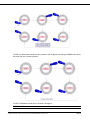
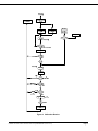
6.2 CALIBRATION
Set the Gassonic 1701 into Observer-H Gain Test (see Gassonic 1701 User Manual for details). Set the
Gassonic Observer-H into Calibration mode by holding the magnet stick on the ENTER switch for more
than 3 seconds. The Observer-H will display a flashing ”CAL”. Verify the need for calibration by
activating the ENTER switch one more time. The Observer-H will now display a flashing ”1701”. This
indicates that the Gassonic Observer-H is ready for calibration and is awaiting communication from the
Gassonic 1701 unit.
Turn the Gassonic 1701 onto the Gassonic Observer-H and activate the calibration by pressing ENTER
or TEST button. The calibration sequence is automatic. If communication between the Gassonic
Observer-H and the Gassonic 1701 is broken ”EER” will be displayed and the unit will return to normal
operation. If the calibration sequence was completed successfully and adjustments were made ”ADJ”
will be displayed for 2 seconds and the unit will return to normal operation. If the calibration sequence
was completed successfully and adjustments were not necessary ”OK” will be displayed for 2 seconds
and the unit will return to normal operation. A calibration event will be recorded.
Installation and User Guide for Gassonic Observer-H (MANOBSERVER-H, Rev C/3-12)
Page 35
Figure 9: Calibration Routine
Installation and User Guide for Gassonic Observer-H (MANOBSERVER-H, Rev C/3-12)
Page 36
7.0 MODBUS DIGITAL INTERFACE
The Observer-H is available in a Dual Modbus configuration and in a Single Modbus + HART
configuration. For the Dual Modbus configuration, two independent Modbus communication channels
are provided and referred to as Comm 1 and Comm 2. For the Single Modbus + HART configuration,
the Modbus channel is referred to as Comm 1.
NOTE: The Dual Modbus configuration disables HART communication.
7.1 BAUD RATE
The Baud Rate is a selectable setting via the Modbus communications interface. The selectable baud
rates are 19.2K, 9600, 4800, or 2400 bits per second.
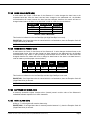
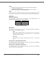
7.2 DATA FORMAT
The Data Format is a selectable setting via the Modbus communications interface. The selectable data
formats are as follows:
Data Bits
8
8
8
8
Parity
None
Even
Odd
None
Stop Bit
1
1
1
2
Format
8-N-1
8-E-1
8-O-1
8-N-2
Table 6: Data Format
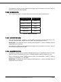
7.3 MODBUS READ STATUS PROTOCOL (QUERY/RESPONSE)
7.3.1
MODBUS READ QUERY MESSAGE
Byte
1st
2nd
3rd
4th
5th
6th
7th
8th
Modbus
Slave
Address
Function
Code
Starting
Address Hi**
Starting
Address Lo**
No. of
Registers Hi
No. of
Registers Lo
CRC Lo
CRC Hi
Range
1-247 *
03
Referenced to Observer-H
Observer-H ID (Address)
(X = 0 or 1 Model Type)
Read Holding Registers
00
Not Used by Observer-H
00-FF (Hex)
Observer-H Commands
00
Not Used by Observer-H
01
No. of 16 Bit Registers
00-FF (Hex)
00-FF (Hex)
CRC Lo Byte
CRC Hi Byte
Table 7: Modbus Query Messages
NOTE*:
Address 0 is reserved for broadcast mode and is not be supported at this time.
NOTE**:
Start Address can be a maximum of 247 Address Locations (0000-0x00F7).
Installation and User Guide for Gassonic Observer-H (MANOBSERVER-H, Rev C/3-12)
Page 37
7.3.2
MODBUS READ RESPONSE MESSAGE
Byte
1st
2nd
3rd
4th
5th
6th
7th
Modbus
Slave
Address
Function
Code
Byte Count
Data Hi
Data Lo
CRC Lo
CRC Hi
Range
1-247* (Decimal)
Referenced to Observer-H
Observer-H ID (Address)
03 or 04
Read Holding Registers
02 – FF (Hex)
00-FF (Hex)
00-FF (Hex)
00-FF (Hex)
00-FF (Hex)
No. of Data Bytes
Observer-H Hi Byte Status Data
Observer-H Lo Byte Status Data
CRC Lo Byte
CRC Hi Byte
Table 8: Modbus Read Response Messages
NOTE: Address 0 is reserved for broadcast mode and will not be supported at this time.
7.4 MODBUS WRITE COMMAND PROTOCOL (QUERY/RESPONSE)
7.4.1
MODBUS WRITE QUERY MESSAGE
Byte
1st
Modbus
Slave Address
2nd
3rd
Range
Referenced to Observer-H
Observer-H ID (Address)
Function Code
Register Address
1-247*
(Decimal)
06
00
Preset Single Register
Not used by Observer-H
Hi**
Register Address
00-FF (Hex)
Observer-H Commands
Lo**
Preset Data Hi
00-FF (Hex)
6th
Preset Data Lo
00-FF (Hex)
7th
8th
CRC Lo
CRC Hi
00-FF (Hex)
00-FF (Hex)
Observer-H Hi Byte Command
Data
Observer-H Lo Byte Command
Data
CRC Lo Byte
CRC Hi Byte
4
th
5
th
Table 9: Modbus Write Query Message
NOTE*:
Address 0 is reserved for broadcast mode and is not be supported at this time.
**
NOTE :
Start Address can be a maximum of 247 Address Locations (0000-0x00F7).
Installation and User Guide for Gassonic Observer-H (MANOBSERVER-H, Rev C/3-12)
Page 38
7.4.2
MODBUS WRITE RESPONSE MESSAGE
Byte
1st
Modbus
Slave Address
2nd
3rd
5th
Function Code
Register Address
Hi**
Register Address
Lo**
Preset Data Hi
6th
Preset Data Lo
00-FF (Hex)
7th
8th
CRC Lo
CRC Hi
00-FF (Hex)
00-FF (Hex)
4th
Range
1-247*
(Decimal)
06
00
Referenced to Observer-H
Observer-H ID (Address)
Preset Single Register
Not used by Observer-H
00-FF (Hex)
Observer-H Commands
00-FF (Hex)
Observer-H Hi Byte Command
Data
Observer-H Lo Byte Command
Data
CRC Lo Byte
CRC Hi Byte
Table 10: Modbus Write Response Message
7.4.3
NOTE*:
Address 0 is reserved for broadcast mode and is not supported at this time.
NOTE**:
Start Address can be a maximum of 247 Address Locations (0000-0x00F7).
FUNCTION CODES SUPPORTED
Function Code 03 or 04 (Read Holding Registers) is used to read status from the slave unit. Function
Code 06 (Preset Single Register) is used to write a command to the slave unit.
7.5 EXCEPTION RESPONSES AND EXCEPTION CODES
In a normal exchange, the master device sends a query to the Observer-H. The Observer-H receives
the query and returns a normal response to the master. If a normal communications error occurs, there
are 4 possible responses from the Observer-H:
1. If the Observer-H does not recognize the query due to a communications error, then no response is
returned from the Observer-H and the master device will eventually process a timeout condition for the
query.
2. If the Observer-H receives the query, but detects a communication error (CRC, etc.), then no response
is returned from the Observer-H and the master device will eventually process a timeout condition for
the query.
3. An exception code is returned when the Observer-H receives the query without a communications
error, but cannot process it due to reading or writing to a non-existent or illegal Function Code, Illegal
Command Starting Address or Register Address, or Illegal Data Value. The exception response
message has two fields that differentiate it from a normal response. See the next section for more
information.
Installation and User Guide for Gassonic Observer-H (MANOBSERVER-H, Rev C/3-12)
Page 39
7.5.1
EXCEPTION RESPONSES
Byte
1st
2nd
3rd
Modbus
Slave Address
Function Code
Exception Code
Range
1-247* (Decimal)
83 or 86 (Hex)
01 - 06 (Hex)
4th
5th
CRC Lo
CRC Hi
00-FF (Hex)
00-FF (Hex)
Referenced to Observer-H
Observer-H ID (Address)
MSB is set with Function Code
Appropriate Exception Code (See
below)
CRC Lo Byte
CRC Hi Byte
Table 11: Exception responses
7.5.2
EXCEPTION CODE FIELD
In a normal response, the Observer-H returns data and status in the data field, requested in the query
from the master. In an exception response, the Observer-H returns an exception code in the data field,
which describes the condition that caused the exception. Below is a list of exception codes that are
supported by the Observer-H:
Code
01
Name
Illegal Function
02
Illegal Data Address
03
Illegal Data Value
04
Slave Device Failure
05
Acknowledge
06
Device Busy
Description
The function code received in the query is not an
allowable action for the Observer-H.
The data address received in the query is not an
allowable address for the Observer-H.
A value contained in the query data field is not an
allowable value for the Observer-H.
An unrecoverable error occurred while the
Observer-H was attempting to perform the
requested action.
The Observer-H has accepted the request and is
processing it, but a long duration of time will be
required. This response is returned to prevent a
timeout error from occurring in the master.
The Observer-H is engaged in processing a longduration program command. The master should
retransmit the message later when the slave is
free.
Table 12: Exception Code Field
7.6 COMMAND REGISTER LOCATIONS
7.6.1
OPERATIONAL MODE COMMANDS
See Section number listed below and reference Section 7.7 for details of each register.
NOTE: The Observer-H has Modbus error reporting. The optional dual Modbus has error reporting for
each channel. It can also provide simultaneous block mode.
Installation and User Guide for Gassonic Observer-H (MANOBSERVER-H, Rev C/3-12)
Page 40
R - indicates Read Only Access
Address
Name
0x0000
Analog Output
Scaled 0-20 mA current
output
0x0001
Mode
Set/view operating mode
Function
Type
GENERAL USER REGISTERS
0x0002
Fault Status 1
User status errors
0x0003
Fault Status 2
Internal status errors
0x0004
Model No.
Observer-H model number
0x0005
Software Rev
Hi
Embedded software major
revision
0x0006
Sound Level
Sound pressure level (dB)
0x0007
Peak Sound
Peak sound level (dB)
0x0008
Temperature
Unit temperature in 0.1 °C
0x0009
0x000A
Display Chars
Hi
Display Chars
Lo
R/W - indicates Read/Write Access
Display MSD and MID1
Display MID2 and LSD
0x000B
Serial No. Hi
Unit serial number - high
word
0x000C
Serial No. Lo
Unit serial number - low word
0x000D
Trigger Level
Set/view alarm trigger level
0x000E
Alarm Delay
Set/view alarm delay time
0x000F
CH1 Address
Set/view channel 1 address
0x0010
CH1 Baud
Rate
0x0011
CH1 Format
Set/view channel 1 baud rate
(2.4, 4.8, 9.6, 19.2 kbps)
Set/view channel 1 data
format
(8N1, 8E1, 801, 8N2)
0x0012
CH2 Address
Set/view channel 2 address
0x0013
CH2 Baud
Rate
0x0014
CH2 Format
0x0015
Software Rev
Hi
Set/view channel 2 baud rate
(2.4, 4.8, 9.6, 19.2 kbps)
Set/view channel 2 data
format
(8N1, 8E1, 801, 8N2)
Embedded software minor
revision
0x0016
Reset Alarms
Set to clear all alarms
0x0017
Cal Sub Mode
0x0018
Acoustic Test
0x0019
HazardWatch
Enables HazardWatch flag
0x001A
Relay State
Indicates the state of relays
Shows the stages of
Calibration
Initiates the acoustic test
routine
Installation and User Guide for Gassonic Observer-H (MANOBSERVER-H, Rev C/3-12)
I/O Range
R/W
0 – 21.7mA
expressed in A
R
See description
R/W
See description
R
See description
R
TBD
R
Alphanumeric
R
~ 45 – 110 dB
R
TBD
R
–40°C – +75°C
expressed in 0.1
°C
R
See description
R
See description
R
See description
R
See description
R
See description
R/W
See description
R/W
1 – 247
R/W
Code
0, 1, 2, 3
R/W
Code
0, 1, 2, 3
R/W
Numeric
Value
1 – 247
R/W
Numeric
Value
Bit
Map
Bit
Map
Bit
Map
Numeric
Value
ASCII
chars
Numeric
Value
Numeric
Value
Numeric
Value
ASCII
chars
ASCII
chars
ASCII
chars
ASCII
chars
Numeric
Value
Numeric
Value
Numeric
Value
Code
Code
ASCII
chars
Numeric
Value
Numeric
Value
Numeric
Value
Numeric
Value
Bit
0, 1, 2, 3
0, 1, 2, 3
Alphanumeric
0
See description
R/W
R/W
R
R/W
R
0–1
R/W
0 -1
R/W
See description
R
Page 41
Address
Name
Function
Number of Modbus channel 1
function code errors
Map
Numeric
Value
Numeric
Value
Numeric
Value
Numeric
Value
Numeric
Value
Numeric
Value
Numeric
Value
Numeric
Value
Number of Modbus channel 1
starting address errors
Numeric
Value
Number of Modbus channel 1
register errors
Number of Modbus channel 1
Hi CRC errors
Number of Modbus channel 1
Lo CRC errors
Number of serial channel 1
parity errors
Number of serial channel 1
overrun errors
Number of serial channel 1
framing errors
Total number of Modbus
channel 1 receive errors
Set factory defaults for alarm
and relay settings
Clears UART total receive
error counters
Clears Modbus total receive
error counters
Sets minimum analog output
current for HART protocol
Indicates presence of HART
hardware
Numeric
Value
Numeric
Value
Numeric
Value
Numeric
Value
Numeric
Value
Numeric
Value
Numeric
Value
Numeric
Value
Numeric
Value
Numeric
Value
Numeric
Value
Numeric
Value
0x001B
Alarm Latch
Set/clear alarm latching state
0x001C
Relay Energize
Set/clear relay energize state
0x001D
HART Enable
Enable HART on channel 2
0x001E
HART Test
Test HART communication
0x001F
Cal Abort
Abort calibration
Ch1 UART
Receive Errors
Ch1 Bus
Activity Rate
Ch1 Function
Code Errors
Ch1 Starting
Address
Errors
Ch1 Register
Errors
Ch1 CRC Hi
Errors
Ch1 CRC Lo
Errors
Ch1 Parity
Errors
Ch1 Overrun
Errors
Ch1 Framing
Errors
Ch1 Modbus
Receive Errors
Factory
Defaults
Clear Ch1
UART Errors
Clear Ch1
Modbus Errors
Total number of UART
channel 1 receive errors
0x0020
0x0021
0x0022
0x0023
0x0024
0x0025
0x0026
0x0027
0x0028
0x0029
0x002A
0x002B
0x002C
0x002D
0x002E
HART Min AO
0x002F
HART Present
Flag
Type
Serial Ch1 bus activity rate
I/O Range
R/W
0 or 1
R/W
0 or 1
R/W
0 or 1
R/W
0, 1, 2
R/W
1
R/W
0 – 65535
R
0 – 100
R
0 – 65535
R
0 – 65535
R
0 – 65535
R
0 – 65535
R
0 – 65535
R
0 – 65535
R
0 – 65535
R
0 – 65535
R
0 – 65535
R
1
R/W
0
R/W
0
R/W
0 – 3.5 mA
1 – 1.25 mA
0 – not present
1 – present
R/W
R
EVENT LOGGING REGISTERS
0x0030
Run Time Hi
0x0031
Run Time Lo
0x0032
Real Time
Clock Year,
Month
0x0033
Real Time
Clock
Day, Hour
0x0034
Real Time
Read/Set run-time seconds
High word
Read/Set run-time seconds
Low word
Numeric
Value
Numeric
Value
Read/Set year and month
of Real-Time Clock (RTC)
0 – 65535
R/W
0 – 65535
R/W
Numeric
Value
1 – 99 year,
1 – 12 month
R/W
Read/Set day and hour of
RTC
Numeric
Value
1 – 31 day,
0 – 23 hour
Read/Set minutes and
Numeric
0– 59 minutes
0 – 59 seconds
Installation and User Guide for Gassonic Observer-H (MANOBSERVER-H, Rev C/3-12)
R/W
Page 42
Address
Name
Clock
Function
seconds of RTC
Type
Value
I/O Range
R/W
Minute,
Second
0x0035
Power Cycled
Flag
Time Reset After power
Cycled
Numeric
Value
0 = Time not
Reset,
1 = Time Reset
0x0036
Event Index
Index of Logged Events
Numeric
Value
0–9
R
R/W
Reserved
0x0037
Reserved
Reserved
0x0038
Reserved
Reserved
0x0039
Reserved
Reserved
0x003A
Reserved
Reserved
0x003B
Reserved
Reserved
0x003C
Reserved
Reserved
0x003D
Reserved
Reserved
0x003E
Reserved
Reserved
0x003F
Run Time Hi
0x0040
Run Time Lo
0x0041
Numeric
Value
Numeric
Value
Numeric
Value
Numeric
Value
Numeric
Value
Numeric
Value
Numeric
Value
Numeric
Value
0
R
0
R
0
R
0
R
0
R
0
R
0
R
0
R
0 - 65535
R
0 - 65535
R
R
Alarm Event Log
Running Time Hi for Alarm
Event log entries
Running Time Low for Alarm
Event log entries
Numeric
Value
Numeric
Value
Clock Time
Hi
Hi byte = year, Lo byte
month: Alarm clock time
Numeric
Value
1 –99 year,
1– 12 month
Clock Time
Mid
Clock Time
Low
Hi byte = Day, Lo byte Hour:
Alarm clock time
Numeric
Value
Hi byte = Minute, Lo byte
second: Alarm clock time
0x0044
Reserved
Reserved
0x0045
Reserved
Reserved
0x0046
Alarm Count
Total Alarm Event Count
Numeric
Value
Numeric
Value
Numeric
Value
Numeric
Value
1 – 31 day,
0 – 23 hour
0 – 59 minutes
0 – 59 seconds
0x0047
Run Time Hi
0x0048
Run Time Lo
0x0049
Clock Time Hi
0x0042
0x0043
0x004A
0x004B
0x004C
Fault Event Log
Running Time Hi for Fault
Event log entries
Running Time Low for Fault
Event log entries
Hi byte = year, Lo byte
month: Fault clock time
Numeric
Value
Numeric
Value
Numeric
Value
Clock Time
Mid
Clock Time
Low
Hi byte = Day, Lo byte Hour:
Fault clock time
Numeric
Value
Hi byte = Minute, Lo byte
second: Fault clock time
Fault Cause
Observer-H-H fault code
Numeric
Value
Numeric
Value
Installation and User Guide for Gassonic Observer-H (MANOBSERVER-H, Rev C/3-12)
R
R
0
R
0
R
0 – 65535
0 - 65535
R
0 - 65535
R
1 –99 year,
1– 12 month
1 – 31 day,
0 – 23 hour
0 – 59 minutes
0 – 59 seconds
R
See description
R
R
R
Page 43
Address
Name
Function
0x004D
Reserved
Reserved
0x004E
Fault Count
Total Fault Event Count
0x004F
Run Time Hi
0x0050
Run Time Lo
0x0051
Clock Time Hi
0x0052
Clock Time
Mid
0x0053
Clock Time
Low
0x0054
Maint. Code
Maintenance Event Log
Running Time Hi for
Maintenance Event log
entries
Running Time Low for
Maintenance Event log
entries
Hi byte = year, Lo byte
month: Maintenance clock
time
Hi byte = Day, Lo byte Hour:
Maintenance clock time
Hi byte = Minute, Lo byte
second: Maintenance clock
time
Observer-H-H maintenance
code
0x0055
Reserved
Reserved
0x0056
Maint. Count
0x0057
Run Time Hi
0x0058
Run Time Lo
0x0059
Clock Time Hi
0x005A
Clock Time
Mid
Clock Time
Low
Total maintenance event
count
Calibration Event Log
Running Time Hi for
calibration event log entries
Running Time Low for
calibration event log entries
Hi byte = year, Lo byte
month: calibration clock time
0x005D
Reserved
Reserved
0x005E
Cal Count
Total calibration event count
0x005F
Clear All
Events
Set to clear all event logs
R
0 – 65535
R
Numeric
Value
0 - 65535
R
Numeric
Value
1 –99 year,
1– 12 month
R
Numeric
Value
1 – 31 day,
0 – 23 hour
R
Numeric
Value
0 – 59 minutes
0 – 59 seconds
R
See description
R
0
R
Numeric
Value
Numeric
Value
Numeric
Value
Numeric
Value
Numeric
Value
Numeric
Value
Numeric
Value
Numeric
Value
Numeric
Value
Numeric
Value
Cal Code
0
R/W
0 - 65535
Numeric
Value
0x005C
I/O Range
Numeric
Value
Hi byte = Day, Lo byte Hour:
calibration clock time
Hi byte = Minute, Lo byte
second: calibration clock time
Observer-H-H calibration
code
0x005B
Type
Numeric
Value
Numeric
Value
Numeric
Value
0 – 65535
0 - 65535
R
0 - 65535
R
1 –99 year,
1– 12 month
1 – 31 day,
0 – 23 hour
0 – 59 minutes
0 – 59 seconds
R
See description
R
0
R
R
R
0 – 65535
0
MISCELLANEOUS USER REGISTERS
0x0060 –
0x006F
0x0070
0x0071
0x0072
0x0073
User Info
User information registers
Numeric
Value
Ch2 UART
Receive Errors
Ch2 Bus
Activity Rate
Ch2 Function
Code Errors
Ch2 Starting
Address
Total number of UART
channel 2 receive errors
Serial channel 2 bus activity
rate
Number of Modbus channel 2
function code errors
Number of Modbus channel 2
starting address errors
Numeric
Value
Numeric
Value
Numeric
Value
Numeric
Value
Installation and User Guide for Gassonic Observer-H (MANOBSERVER-H, Rev C/3-12)
0 – 65535
0 – 65535
R
0 – 100
R
0 – 65535
R
0 – 65535
R
Page 44
Address
0x0074
0x0075
0x0076
0x0077
0x0078
0x0079
0x007A
0x007B
0x007C
0x007D
0x007E
Name
Function
Type
Errors
Ch2 Register
Errors
Ch2 CRC Hi
Errors
Ch2 CRC Lo
Errors
Ch2 Parity
Errors
Ch2 Overrun
Errors
Ch2 Framing
Errors
Ch2 Modbus
Receive Errors
I/O Range
Number of Modbus channel 2
register errors
Number of Modbus channel 2
Hi CRC errors
Number of Modbus channel 2
Lo CRC errors
Number of serial channel 2
parity errors
Number of serial channel 2
overrun errors
Number of serial channel 2
framing errors
Total number of Modbus
channel 2 receive errors
Reserved
N/A
Clear Ch1
UART Errors
Clear Ch1
Modbus Errors
Clears UART total receive
error counters
Clears Modbus total receive
error counters
Reserved
N/A
Numeric
Value
Numeric
Value
Numeric
Value
Numeric
Value
Numeric
Value
Numeric
Value
Numeric
Value
Numeric
Value
Numeric
Value
Numeric
Value
Numeric
Value
R/W
0 – 65535
R
0 – 65535
R
0 – 65535
R
0 – 65535
R
0 – 65535
R
0 – 65535
R
0 – 65535
R
N/A
R
0
R/W
0
R/W
N/A
R
Table 13: Modbus Commands
7.7 OBSERVER-H COMMAND REGISTER DETAILS
7.7.1
ANALOG (00H)
A read returns a value which is proportional to the 0-20 mA output current. The current is based on a
16-bit value. The number represents the current in microamps (A).
7.7.2
MODE (01H)
A read returns the Observer-H status mode
Bit Position
Fault
Description
Hex Value
Decimal Value
Bit Position
Fault
Description
Hex Value
Decimal Value
15
14
13
12
11
10
9
8
Not
Not
Not
Not
Show
Alarm
Piezo
Cal
Used
Used
Used
Used
Rev
Mode
Cal
Pending
0x8000
0x4000
0x2000
0x1000
0x0800
0x0400
0x0200
0x0100
32768
16384
8192
4096
2048
1024
512
256
7
6
5
4
3
2
1
0
Alarm
Not
Setup
Fault
Cal
Acoustic
Run
Startup
Test
Used
Mode
Mode
Mode
Test
Mode
Mode
0x0080
0x0040
0x0020
0x0010
0x0008
0x0004
0x0002
0x0001
128
64
32
16
8
4
2
1
Table 14: Operation Status Mode
READ:
A read request to this register returns the present Observer-H operating mode represented by the
enabled bit. Descriptions of the modes are provided below:
Startup: Observer-H initialization during the power-up cycle.
Run: Normal operating mode of the instrument.
Installation and User Guide for Gassonic Observer-H (MANOBSERVER-H, Rev C/3-12)
Page 45
Acoustic Test: This bit is set anytime an acoustic test is taking place. The request of the
acoustic test can be from the magnet, a timed acoustic test, a HART request or a Modbus
request.
Calibrate: This bit is set anytime a calibration is taking place. The request of the calibration
test can be from the magnet, a timed acoustic test, a HART request or a Modbus request.
Fault: This bit is set any time the Observer-H has a fault.
Setup: Indicates the user has activated a magnet and is in setup mode.
Alarm Test: This indicates someone has activated the alarm test. This can be done via a
remote switch, HART, or Modbus.
Calibration Pending: The Cal pending bit is used to indicate an intermediate state.
Piezo Calibration: This bit is not used in normal operation. It is used only when the piezo or
microphone is replaced. It is set when the technician calibrates the piezo.
Alarm: This bit is used when the Observer-H detects dB greater than the trigger level. If the
Observer-H is latched it will stay in alarm mode until the reset relay is activated.
Show Rev: This bit is set during the time someone has activated the show rev by using an UP
& DOWN magnet.
WRITE:
A write to the mode register (01) with the proper bit set will cause the Observer-H to change modes.
Not all modes can be activated in this manner. If an improper bit or the action is not allowed at this time
an exception will be returned.
7.7.3
Alarm Test: The alarm bit is a toggle. The first write sets the mode the second write clears
the mode.
Acoustic Test: This mode will perform a non continuous acoustic test. The acoustic test will
not be allowed if a gas leak is above the trigger level, instead an exception will be returned.
The display will show a “COM”.
Calibrate: This will put the Observer-H into calibration mode. It will be ready for the 1701 to
be activated. Calibration will not be allowed if a gas leak is above the trigger level instead an
exception will be returned.
Operational Mode: Writing an operational mode bit will abort any of the above modes. It will
not go back to operational mode until it is safe.
PRIMARY FAULT STATUS/ERROR 1 (02H)
A read returns the errors that are occurring, which are indicated by bit position. This status word is
used as the primary status error word. This is the only one that needs to be read to know if there are
any errors.
Bit Position
Fault
Description
Hex Value
Decimal
Value
Display
Fault Code
15
Error
Lower
level
0x8000
14
Not
Used
BELOW
ATREF
13
0x4000
0x2000
32768
16384
8192
12
Not
Used
11
Event
Memory
10
Hart
Memory
9
User
Memory
8
Critical
Memory
0x100
0
4096
0x0800
0x0400
0x0200
0x0100
2048
1024
512
256
EEVT
EHRT
EUSR
ECRT
N/A
Installation and User Guide for Gassonic Observer-H (MANOBSERVER-H, Rev C/3-12)
Page 46
Bit Position
Fault
Description
7
Internal
Voltage
6
Magnet
Switch
5
Reset
Switch
4
Alarm
Switch
3
Not
used
2
Acoustic
Test
1
Not
Used
Hex Value
0x0080
0x0040
0x0020
0x0008
0x0004
0x0002
Decimal
Value
Display
Fault Code
128
64
32
0x001
0
16
0
24V
Low
Line
0x0001
8
4
2
1
EINV
EMAG
ERSW
EASW
ERAC
ERV_
Table 15: Fault Status/Error 1
See the ERROR OUTPUT Section for explanation of errors. Bit 13 is a special bit for Modbus and
HART. If the Observer-H is in acoustic test this bit is a one if the acoustic sound level is above the
desired level. It is a zero if it is below the desired level. This allows the system to quickly know if there
is an acoustic test problem.
Bit 15 is a “one” if any of the lower level faults are present. The system can now drill down and find the
root cause. This is not normally required at the system level only at a test station.
7.7.4
FAULT STATUS/ERROR 2 (03H)
A read-only accessible register contains the bit map for any internal error that is present. The following
table shows the faults that are represented by each bit in the register.
Bit Position
Fault
Description
Hex Value
Decimal Value
Display Fault
Code
Bit Position
Fault
Description
Hex Value
Decimal Value
Display Fault
Code
15
14
13
12
11
10
9
8
Word
Event
HART
System
Critical
Event
HART
System
3
RAM
RAM
RAM
RAM
Flash
Flash
Flash
0x8000
0x4000
0x2000
0x1000
0x0800
0x0400
0x0200
0x0100
32768
16384
8192
4096
2048
1024
512
256
N/A
N/A
N/A
N/A
N/A
N/A
N/A
N/A
7
6
5
4
3
2
1
0
Critical
CPU
CPU
-5V
+5V
-12V
+12V
Current
Flash
RAM
Flash
Ref.
Ref.
Ref.
Ref.
Ref.
0x0080
0x0040
0x0020
0x0010
0x0008
0x0004
0x0002
0x0001
128
64
32
16
8
4
2
1
N/A
N/A
N/A
N/A
N/A
N/A
N/A
N/A
Table 16: Fault Status/Error 2
7.7.5
MODEL TYPE (04H)
A read returns the Decimal Value indicating the model number. The Observer-H model number is
“6000” Notice: If a newer Observer-H is designed to replace the Observer-H the model number will be
different.
7.7.6
SOFTWARE REVISION MAJOR (05H)
A read-only accessible register contains the major (user) alphanumeric revision value of the ObserverH embedded software expressed in 2 ASCII characters (REV “A” appears as a blank and the letter A).
Installation and User Guide for Gassonic Observer-H (MANOBSERVER-H, Rev C/3-12)
Page 47
7.7.7
DB LEVEL
(06H)
A read-only accessible register contains the value of the measured sound pressure level expressed in
decibels.
7.7.8
PEAK SOUND
(07H)
A read-only accessible register contains the acoustic test peak sound level expressed in decibels.
7.7.9
UNIT TEMPERATURE (08H)
A read-only accessible register contains the value of internal unit temperature expressed in 0.1°C units.
These functions are indicated on the Low Data Byte and the High Data Byte is not used.
7.7.10 MODBUS DISPLAY (09H, 0AH)
09H: A read-only accessible register contains the upper two ASCII characters shown on the ObserverH display.
0AH: A read-only accessible register contains the lower two ASCII characters shown on the Observer-H
display.
7.7.11 SERIAL NUMBER (0BH, 0CH)
The serial number is a 32-bit word but the value is only 23 bits long. The upper bits are always zero.
This is done to keep the same serial number as the HART serial number. Address 0x16 contains the
lower part of the number and address 0X15 contains the upper part.
7.7.12 TRIGGER LEVEL (0DH)
This is a read/write register. A read will return the present trigger level. Since the trigger level can only
be incremented by 5, only certain values are allowed.
EXCEPTION - If an illegal data value is entered (must be one of the numbers in the table), then the
Exception Code 03 (Illegal Data Value) is returned
Valid Trigger levels
59
64
69
74
79
84
89
94
99
dB
Table 17: Trigger Levels
7.7.13 TRIGGER DELAY (0EH)
This is a read/write register. A read will return the present time delay. The time delay has a range of 0
to 600 seconds. A one represents 10 seconds.
EXCEPTION - If an illegal data value is entered (must be between 0-600), then the Exception Code 03
(Illegal Data Value) is returned
7.7.14 COMM 1 ADDRESS (0FH)
A read returns the Comm 1 address of the Observer-H. A write changes the address to the requested
address. The range of the address is 1 to 247 (01 to F7 Hex). After the address has been changed to
the slave unit, the Modbus communications will cease because the address has changed; therefore the
master will have to change its query address to the slave’s new address in order to restart the
communications.
EXCEPTION - If an illegal data value is entered (must be between 1-0x00F7), then the Exception Code
03 (Illegal Data Value) is returned.
NOTE: The default Address is 1.
Installation and User Guide for Gassonic Observer-H (MANOBSERVER-H, Rev C/3-12)
Page 48
7.7.15 COMM 1 BAUD RATE (10H)
A read returns the Comm 1 baud rate of the Observer-H A write changes the baud rate to the requested
baud rate. After the baud rate has been changed to the addressed unit, the Modbus communications
will cease because the baud rate has changed; therefore the master will have to change its baud rate to
the slave’s new baud rate in order to restart the communications.
Baud Rate
19.2K
9600
4800
2400
Low Data Byte
04
03
02
01
Access
Read/Write
Read/Write
Read/Write
Read/Write
Table 18: Comm 1 Baud Rate
This function is indicated on the Low Data Byte (the High Data Byte is not used).
EXCEPTION - If an illegal data value is entered which is not listed above, then the Exception Code 03
(Illegal Data Value) is returned.
NOTE: The default baud rate is 19200.
7.7.16 COMM 1 DATA FORMAT (11H)
A read returns the Comm 1 data format of the Observer-H. A write changes the data format to the
requested data format. After the data format has been changed to the addressed unit, the Modbus
communications may cease or start producing Comm errors because the data format has changed;
therefore the master will have to change its data format to the slave’s new data format in order to restart
or provide proper communications.
Data
Parity
Stop
Format
8
8
8
8
None
Even
Odd
None
1
1
1
2
8-N-1
8-E-1
8-O-1
8-N-2
Low Data
Byte
00
01
02
03
Access
Read/Write
Read/Write
Read/Write
Read/Write
Table 19: Comm 1 Data Format
This function is indicated on the Low Data Byte and the High Data Byte is not used.
EXCEPTION - If an illegal data value is entered which is not listed above, then the Exception Code 03
(Illegal Data Value) is returned.
NOTE: The default Data Format is 8-N-1.
7.7.17 COMM 2 ADDRESS (12H)
A read returns the Comm 2 address of the Observer-H. A write changes the address to the requested
address. The range of the address is 1 to 247 (01 to F7 Hex). After the address has been changed to
the slave unit, the Modbus communications will cease because the address has changed; therefore the
master will have to change its query address to the slave’s new address in order to restart the
communications.
EXCEPTION - If an illegal data value is entered (must be between 1-0x00F7), then the Exception Code
03 (Illegal Data Value) is returned.
NOTE: The default address is 2.
Installation and User Guide for Gassonic Observer-H (MANOBSERVER-H, Rev C/3-12)
Page 49
7.7.18 COMM 2 BAUD RATE (13H)
A read returns the Comm 2 baud rate of the Observer-H. A write changes the baud rate to the
requested baud rate. After the baud rate has been changed to the addressed unit, the Modbus
communications will cease because the baud rate has changed; therefore the master will have to
change its baud rate to the slave’s new baud rate in order to restart the communications.
Baud Rate
19.2K
9600
4800
2400
Low Data Byte
04
03
02
01
Access
Read/Write
Read/Write
Read/Write
Read/Write
Table 20: Comm 2 Baud Rate
This function is indicated on the Low Data Byte (the High Data Byte is not used).
EXCEPTION - If an illegal data value is entered which is not listed above, then the Exception Code 03
(Illegal Data Value) is returned.
NOTE: The default Baud Rate is 19200.
7.7.19 COMM 2 DATA FORMAT (14H)
A read returns the Comm 2 data format of the Observer-H. A write changes the data format to the
requested data format. After the data format has been changed to the addressed unit, the Modbus
communications may cease or start producing communication errors because the data format has
changed; therefore the master will have to change its data format to the slave’s new data format in
order to restart or provide proper communications.
Data
Parity
8
8
8
8
None
Even
Odd
None
Low Data
Byte
1
8-N-1
00
1
8-E-1
01
1
8-O-1
02
2
8-N-2
03
Table 21: Comm 2 Data Format
Stop
Format
Access
Read/Write
Read/Write
Read/Write
Read/Write
This function is indicated on the Low Data Byte and the High Data Byte is not used.
EXCEPTION - If an illegal data value is entered which is not listed above, then the Exception Code 03
(Illegal Data Value) is returned.
NOTE: The default Data Format is 8-N-1.
7.7.20 SOFTWARE REV MINOR (15H)
A read-only accessible register contains minor (internal) numeric revision value of the Observer-H
embedded software expressed in 2 ASCII characters.
7.7.21 RESET ALARM (16H)
Writing a “1” to this register will reset the alarm relay.
EXCEPTIONS - If an illegal data value is entered (must be between 0-1), then the Exception Code 03
(Illegal Data Value) is returned.
Installation and User Guide for Gassonic Observer-H (MANOBSERVER-H, Rev C/3-12)
Page 50
If the Observer-H hears a gas leak greater than the trigger when the command is received a Code 06
(device busy) exception will be returned.
7.7.22 SUB MODE (17H)
This is a read only register. It is used to tell the control system the states of calibrate mode.
Calibrate Sub Mode
Number returned
Apply 1701
0x0001
Calibration in progress
0x0002
Calibration adjustment
0x0004
Calibrate OK
0x0008
Calibrate error
0x0010
Table 22: Calibrate Sub Mode
7.7.23 ACOUSTIC TEST (18H)
This is a write only register. Writing a “1” to this register will activate an acoustic test. This is a one
cycle test. During the test the display will show “COM”. The current will go to 3.0 mA.
EXCEPTIONS - If an illegal data value is entered (must be between 0-1), then the Exception Code 03
(Illegal Data Value) is returned.
If the Observer-H hears a gas leak greater than the trigger when the command is received a Code 06
(device busy) exception will be returned.
7.7.24 HAZARDWATCH (19H)
HazardWatch indicates when a successful calibration takes place. In HazardWatch mode the current
goes to 3.2 mA for 5 seconds then to 4.0 mA. An aborted calibration would go straight to 4.0 mA.
This is a read/write only register. Reading returns the state of the HazardWatch. (ON/OFF). Writing a
1 will turn on HazardWatch, a “0” will disable.
EXCEPTIONS - If an illegal data value is entered (must be between 0-1), then the Exception Code 03
(Illegal Data Value) is returned.
Installation and User Guide for Gassonic Observer-H (MANOBSERVER-H, Rev C/3-12)
Page 51
7.7.25 RELAY STATE (1AH)
The relay state register is read only. The bit position shows which relay is on.
Function
Hex Value
Alarm Relay Energized
0x0001
Fault Relay Energized
0x0002
1701 LED Energized
0x0004
Table 23: Relay State
7.7.26 ALARM LATCH (1BH)
The alarm latch register is read/write. A read returns if the alarm latch is enabled or not.
enables or disables latching. One is latch zero is non – latched.
A write
EXCEPTIONS - If an illegal data value is entered (must be between 0-1), then the Exception Code 03
(Illegal Data Value) is returned. If the Observer-H hears a gas leak greater than the trigger when the
command is received a Code 06 (device busy) exception will be returned.
7.7.27 RELAY ENERGIZE (1CH)
The relay energized register is read/write. A read returns if the alarm relay is normally energized or not.
One is energized a zero is de-energized.
EXCEPTIONS - If an illegal data value is entered (must be between 0-1), then the Exception Code 03
(Illegal Data Value) is returned. If the Observer-H hears a gas leak greater than the trigger when the
command is received a Code 06 (device busy) exception will be returned.
7.7.28 HART ENABLE (1DH)
The HART enable register read/write. This command enables or disables HART. A “0” is HART
disabled. A “1” is HART Enabled. This is an option that must be ordered.
EXCEPTIONS - If an illegal data value is entered (must be between 0-1), or if HART is not installed
then the Exception Code 03 (Illegal Data Value) is returned.
7.7.29 HART TEST (1EH)
This command is used to test the HART output. It produces constant zeros or constant ones on the
HART output. This is only available if the HART option was purchased.
EXCEPTIONS - If an illegal data value is entered (must be between 0-1), or if HART is not installed
then the Exception Code 03 (Illegal Data Value) is returned.
Code
Results
0
1
2
Normal
Constant ones
Constant zeros
Table 24: HART Codes
Installation and User Guide for Gassonic Observer-H (MANOBSERVER-H, Rev C/3-12)
Page 52
7.7.30 CAL ABORT (1FH)
Writing to the calibrate abort register will abort calibration and return the Observer–H to normal.
7.7.31 COMM 1 TOTAL ILLEGAL NUMBER OF REGISTERS ERRORS (20H)
A read indicates the total illegal number of registers errors on the Comm 1Modbus. The maximum
count is 65535 and then the counter rolls over to zero and begins counting again.
7.7.32 COMM 1 BUS ACTIVITY RATE % (21H)
A read indicates the Comm 1 Bus Activity Rate in percent of this Slave's addressed node versus other
addressed nodes. Range of this value is in hex (0-64), which translates to decimal (0-100%).
7.7.33 COMM 1 FUNCTION CODE ERRORS (22H)
A read indicates the number of Comm Function Code Errors that occurred in the slave device. The
maximum count is 65535 and then the counter rolls over to zero and begins counting again.
7.7.34 COMM 1 STARTING ADDRESS ERRORS (23H)
A read indicates the number of Comm 1 Starting Address Errors that occurred in the slave device. The
maximum count is 65535 and then the counter rolls over to zero and begins counting again.
7.7.35 COMM 1 TOTAL RECEIVE ERRORS (24H)
A read indicates the total Modbus Comm 1 Only Receive Errors that occurred in the slave device.
These are address, function, etc. type of errors. The maximum count is 65535 and then the counter
rolls over to zero and begins counting again.
7.7.36 RXD CRC ERRORS (25H)
A read indicates the number of RXD CRC Errors that occurred in the slave device. The maximum count
is 65535 and then the counter rolls over to zero and begins counting again.
7.7.37 RXD CRC ERRORS (SAME AS 25H) (26H)
Same as (25h).
7.7.38 COMM 1 PARITY ERRORS (27H)
A read indicates the number of Comm 1 Only Parity Errors that occurred in the slave device. The
maximum count is 65535 and then the counter rolls over to zero and begins counting again.
7.7.39 COMM 1 OVERRUN ERRORS (28H)
A read indicates the number of Comm 1 Overrun Errors that occurred in the slave device. The maximum count
is 65535 and then the counter rolls over to zero and begins counting again.
NOTE: An overrun error occurs when the next received byte of data tries to overwrite an existing
received data byte, which has not been processed. Therefore, the next received byte of data is
lost. This can be controlled by implementing the proper DCS or PLC Error Handling Timing
Setting (ex. Reply Timeout Setting, Delay Time, and Number of Retries) and proper Baud Rate
Setting.
7.7.40 COMM 1 FRAMING ERRORS (29H)
A read indicates the number of Comm 1 Framing Errors that occurred in the slave device. The
maximum count is 65535 and then the counter rolls over to zero and begins counting again.
Installation and User Guide for Gassonic Observer-H (MANOBSERVER-H, Rev C/3-12)
Page 53
7.7.41 COMM 1 TOTAL UART RECEIVE ERRORS (2AH)
A read indicates the total Modbus Comm 1 Receive Errors that occurred in the slave device. The
maximum count is 65535 and then the counter rolls over to zero and begins counting again. The total
errors are an accumulation of the individual communication errors such as Overrun, CRC, Parity and
Framing errors.
7.7.42 FACTORY DEFAULT (2BH)
Writing 1 to this register will load the factory default values for alarm, Modbus and HART settings.
The factory default register is read/write. This command can set all the settings to factory default by
writing 1. A read returns “1” if the factory setting is set default or returns “0” if the settings are different
than the factory default.
7.7.43 COMM 1 CLEAR ERROR (2CH)
Writing 1 to this register clears all UART receive communication (framing, overrun, parity) error
counters on serial channel 1.
7.7.44 CLEAR STATS 1(2D)
Writing 1 to this register clears all Modbus (function, starting register address, number of registers,
CRC) error counters on serial channel 1.
7.7.45 HART CURRENT (2E)
Normally in HART mode the low current does not go below 3.5 mA. In order for the current to
distinguish between Fault and offline there is a HART setting that allows the current to go as low as
1.25 mA. A read returns “1” or “0”.
Condition
Normal HART Current
HART Expanded Scale
Units
Run
4 to 20
4 ,8, 12,16, 20
mA
Acoustic Fault
1*
1.25*
mA
Fault
3.5
1.25
mA
Table 25: HART Current Levels
EXCEPTIONS - If an illegal data value is entered (must be between 0-1), then the Exception Code 03
(Illegal Data Value) is returned
7.7.46 HART PRESENT (2F)
HART present is a read only register. A “1” indicates HART is installed. A “0” means HART is not
installed.
NOTE: HART can be installed and not enabled but it cannot be enabled if not installed.
7.7.47 EVENT LOGGING (30H – 5FH)
The Observer-H logs Alarm, Fault, Calibration, and Maintenance events. Each event group will store a
total of 10 events in a first-in-first-out manner. An identifying number and time stamp is also stored for
each event.
Installation and User Guide for Gassonic Observer-H (MANOBSERVER-H, Rev C/3-12)
Page 54
Faults
Whenever the fault word changes the time will be recorded (See Primary fault).
The time of the fault will be saved.
When the fault is removed, it is not saved and the counter is not incremented.
A fault event is logged for every 30 seconds recorded.
Alarm
The time the gas level reaches the Alarm level is recorded. Each time this happens a counter
is incremented. The end of the event is when the sound level goes 5% below the alarm level.
Calibration
Microphone Calibration
When a calibration is finished a counter is incremented for each calibration attempt.
identifying number stored depends on the ending condition.
Condition
Calibrate OK
Calibrate Adjust
Calibrate Error
The
Identifying number
4
5
6
Table 26: Calibration Counter
Maintenance
There are a total of 10 maintenance events stored. The number stored with the time stamp will
indicate the source of the maintenance event.
Piezo
When a Piezo calibration (seven up: seven times on the UP) is saved a
maintenance event will occur. The value stored will be 4. A factory piezo
calibration will have the number 9.
Alarm Test
When an alarm test is initiated, a maintenance event will occur. The event code
will be 6.
Running Time in Seconds Hi Word (0x30)
This sets/reads hi word of device running time in seconds. This value must be read/written
prior to running time low byte (register 0x00B2).
Running Time in Seconds Lo Word (0x31)
This sets/reads hi word of device running time in seconds. This value must be read/written
after running time hi byte (register 0x00B1).
Installation and User Guide for Gassonic Observer-H (MANOBSERVER-H, Rev C/3-12)
Page 55
Item
Number
1
2
3
Description
Hi Byte =Year, Low Byte = Month
Hi Byte = Day, Low Byte = Hour
Hi Byte = Minute, Low Byte = Second
Table 27: Real Time Clock Time Format
Real-time Clock Year, Month (0x32)
This is used to read/write the real time clock. The high byte will be the year minus 2000. The
low byte will be a value from 1 to 12. To get or set real time, read or write year/month (0x00B3)
first, then day/hour (0x00B4), then min/sec (0x00B5)
Real-time Clock Day, Hour (0x33)
This is used to read/write the real time clock. The high byte will be the day of the month from 1
to 31. The low byte will be the hour from 0 to 23. To get or set real time, read or write
year/month (0x00B3) first, then day/hour (0x00B4), then min/sec (0x00B5)
Real-time Clock Minute, Second (0x34)
This is used to read/write the real time clock. The high byte will be the minute from 0 to 59 and
the low byte will be the seconds from 0 to 59. To get or set real time, read or write year/month
(0x00B3) first, then day/hour (0x00B4), then min/sec (0x00B5)
Power Cycle Flag (0x35)
This reads whether the time of day clock has been reset after power has been re-cycled to the
unit. If the time has been reset, this flag will be = 0; otherwise the flag will = 1.
Event Index (0x36)
This is used to indicate which of the stored events the user would like to read. There are 5
event logs: Warning events, Alarm events, Fault events, Calibration events and Maintenance
events. Each of these event logs consist of 10 of their most recent occurrences. The user is
able to read the logs of each of these by setting this event index followed by a reading of the
desired event log. The event index is a number from 0 to 9. Zero refers to the most recent
event and 9 refers to the least recent event stored in the log. For example to read time of the
most recent Warning event in the Warning event log, set this register to 0 and then read
registers 0xB8 and 0xB9 (for the running time in seconds) or read registers 0xBA, 0xBB, and
0xBC (for the clock time).
Reserved (0x37 - 3E )
Alarm Running Time in Seconds, Hi Word (0x3F)
This register reads the high word of the running time in seconds when the alarm event
occurred. This time is in seconds since January 1, 2000.
Alarm Running Time in Seconds, Low Word (0x40)
This register reads the low word of the running time in seconds when the alarm event occurred.
This time is in seconds since January 1, 2000.
Alarm Clock Time: Year, Month (0x41) Alarm Structure Hi
These registers are described in Table 28 as item number 1.
Alarm Clock Time: Day, Hour (0x42) Alarm Structure Mid
These registers are described in Table 28 as item number 2.
Installation and User Guide for Gassonic Observer-H (MANOBSERVER-H, Rev C/3-12)
Page 56
Alarm Clock Time: Minute, Seconds (0x43) Alarm Structure Low
These registers are described in Table 28 as item number 3.
Spare (0x44- 45)
Spare register.
Total Alarm Event Counter (0x46)
This reads the total number of alarm events that have been stored in the unit.
Fault Running Time in Seconds, Hi Word (0x47)
This register reads the high word of the running time in seconds when the fault event occurred.
This time is in seconds since January 1, 2000.
Fault Running Time in Seconds, Low Word (0x48)
This register reads the low word of the running time in seconds when the fault event occurred.
This time is in seconds since January 1, 2000.
Fault Clock Time: Year, Month (0x49) Fault Structure Hi
These registers are described in Table 28 as item number 1.
Fault Clock Time: Day, Hour (0x4A) Fault Structure Mid
These registers are described in Table 28 as item number 2.
Fault Clock Time: Minute, Seconds (0x4B) Fault Structure Low
These registers are described in Table 28 as item number 3.
Fault Code (0x4C) Fault Cause
This register is described in Table 28.
Spare (0x4D)
Spare register.
Total Fault Event Counter (0x4E)
This reads the total number of fault events that have been stored in the unit.
Maintenance Running Time in Seconds, Hi Word (0x4F)
This register reads the high word of the running time in seconds when the gas check event
occurred. This time is in seconds since January 1, 2000.
Maintenance Running Time in Seconds, Low Word (0x50)
This register reads the low word of the running time in seconds when the gas check event
occurred. This time is in seconds since January 1, 2000.
Maintenance Clock Time: Year, Month (0x51)
These registers are described in Table 28 as item number 1.
Maintenance Clock Time: Day, Hour (0x52)
These registers are described in Table 28 as item number 2.
Maintenance Clock Time: Minute, Seconds (0x53)
These registers are described in Table 28 as item number 3.
Installation and User Guide for Gassonic Observer-H (MANOBSERVER-H, Rev C/3-12)
Page 57
Maintenance Cause (0x54)
There are three maintenance event types:
1. User started acoustic test: code = 9
2. Alarm test: code = 8
3. Piezo calibration: code = 4
Spare (0x55)
Spare register.
Total Maintenance Event Counter (0x56)
This reads the total number of gas check events that have been stored in the unit
Calibration Running Time in Seconds, Hi Word (0x57)
This register reads the high word of the running time in seconds when the calibration event
occurred. This time is in seconds since January 1, 2000.
Calibration Running Time in Seconds, Low Word (0x58)
This register reads the low word of the running time in seconds when the calibration event
occurred. This time is in seconds since January 1, 2000.
Calibration Clock Time: Year, Month (0x59)
These registers are described in Table 28 as item number 1.
Calibration Clock Time: Day, Hour (0x5A)
These registers are described in Table 28 as item number 2.
Calibration Clock Time: Minute, Seconds (0x5B)
These registers are described in Table 28 as item number 3.
Calibration Code (0x5C)
This returns 1 for zero events and 2 for calibration events.
Spare (0x5D)
Spare register.
Total Calibration Event Counter (0x5E)
This reads the total number of calibration events that have been stored in the unit.
Clear all events (0x5F)
Writing zero (0) to this register clears all event counters.
Setting Clock
Please see the table on the following page.
Installation and User Guide for Gassonic Observer-H (MANOBSERVER-H, Rev C/3-12)
Page 58
Address
(hex)
Parameter
Function
Data Type
Data range
Access
30
Seconds Time Hi
Seconds Time Hi
Numeric value
0 – 65535
Timer Sec
31
Seconds Time
Low
Seconds Time
Numeric value
0 – 65535
Timer sec
32
Real Time Clock
Year, Month
Read/Set year and
month of RTC
2 Numeric
Values
0-99 year, 1 –
12 month
Timer Struct
33
Real Time Clock
Day, Hour
Read/Set day and
hour of RTC
2 Numeric
Values
1 – 31 day, 0
– 23 hour
34
Real Time Clock
Minute, Second
Read/Set minutes
and seconds of
RTC
2 Numeric
Values
0 – 59 minute,
0 – 59 second
Timer Struct
35
PowerCycleFlag
Read Power Cycle
Flag.
Numeric Value
1 – Time Not
Reset; 0 –
Time Was
Reset
Flag
36
Event Index
Event index of
Logged Event
Numeric value
0-9
Index
37
Warn
Seconds Time Hi
for warning event
log entries
Numeric value
0 – 65535
Warn
Seconds Time Hi
38
Seconds Time
Low
Seconds Time Low
for warning event
log entries
Numeric value
0 – 65535
Warn
39
Structure time Hi
Hi byte – year, low
byte – month for
warning event log
entries
Numeric value
0 – 65535
Warn
Address
(hex)
Parameter
Function
Data Type
Data range
Access
3A
Structure time
Mid
Hi byte – day, low
byte – hour warning
event log entries
Numeric value
0 – 65535
Warn
3B
Structure time
Low
Hi byte – min, low
byte – sec for
warning event log
entries
Numeric value
0 – 65535
Warn
3C
Reserved
Reserved
Numeric value
0
3D
Reserved
Reserved
Numeric value
0
3E
Warn Event
Count
Warning Event
Count
Numeric value
0 – 65535
Installation and User Guide for Gassonic Observer-H (MANOBSERVER-H, Rev C/3-12)
Warn
Page 59
Address
(hex)
Parameter
Function
Data Type
Data range
Access
3F
Alarm Seconds
Time Hi
Seconds Time Hi
for alarm event log
entries
Numeric value
0 – 65535
Alarm
40
Seconds Time
Low
Seconds Time Low
for alarm event log
entries
Numeric value
0 – 65535
Alarm
41
Structure time Hi
Hi byte – year, low
byte – month for
alarm event log
entries
Numeric value
0 – 65535
Alarm
42
Structure time
Mid
Hi byte – day, low
byte – hour alarm
event log entries
Numeric value
0 – 65535
Alarm
43
Structure time
Low
Hi byte – min, low
byte – sec for alarm
event log entries
Numeric value
0 – 65535
Alarm
44
Reserved
Reserved
Numeric value
0
45
Reserved
Reserved
Numeric value
0
46
Alarm Event
Count
Alarm Event Count
Numeric value
0 – 65535
Alarm
47
Fault
Seconds Time Hi
for fault event log
entries
Numeric value
0 – 65535
Fault
Seconds time Hi
48
Seconds time
Low
Seconds Time Low
for fault event log
entries
Numeric value
0 – 65535
Fault
49
Structure time Hi
Hi byte – year, low
byte – month for
fault event log
entries
Numeric value
0 – 65535
Fault
Address
(hex)
Parameter
Function
Data Type
Data range
Access
4A
Structure time
Mid
Hi byte – day, low
byte – hour alarm
event log entries
Numeric value
0 – 65535
Fault
4B
Structure time
Low
Hi byte – min, low
byte – sec for fault
event log entries
Numeric value
0 – 65535
Fault
4C
Fault code
Fault code. Same
code as register 2
Numeric value
0 – 65535
Fault
4D
Reserved
Reserved
Numeric value
0
4E
Fault Event Count
Fault Event Count
Numeric value
0 – 65535
Installation and User Guide for Gassonic Observer-H (MANOBSERVER-H, Rev C/3-12)
Fault
Page 60
Address
(hex)
Parameter
Function
4F
Maintenance
Seconds time Hi
Seconds Time Hi
for event log entries
50
Seconds time
Low
51
Data Type
Data range
Access
Maintenance
Numeric value
0 – 65535
Seconds Time Low
for event log entries
Numeric value
0 – 65535
Maintenance
Structure time Hi
Hi byte – year, low
byte – month for
event log entries
Numeric value
0 – 65535
Maintenance
52
Structure time
Mid
Hi byte – day, low
byte – hour event
log entries
Numeric value
0 – 65535
Maintenance
53
Structure time
Low
Hi byte – min, low
byte – sec for event
log entries
Numeric value
0 – 65535
Maintenance
54
Maintenance
code
Cal check
Numeric value
0
Maintenance
55
Reserved
Reserved
Numeric value
0
56
Maintenance
Count
Maintenance Count
Numeric value
0 – 65535
Maintenance
57
Calibrate
Seconds Time Hi
Seconds Time Hi
for event log entries
Numeric value
0 – 65535
Calibrate
58
Seconds Time
Low
Seconds Time Low
for event log entries
Numeric value
0 – 65535
Calibrate
59
Structure time Hi
Hi byte – year, low
byte – month for
event log entries
Numeric value
0 – 65535
Calibrate
5A
Structure time
Mid
Hi byte – day, low
byte – hour event
log entries
Numeric value
0 – 65535
Calibrate
Address
(hex)
Parameter
Function
Data Type
Data range
Access
5B
Structure time
Low
Hi byte – min, low
byte – sec for
event log entries
Numeric value
0 – 65535
Calibrate
5C
Calibrate code
Cal
Numeric value
0
Calibrate
5D
Reserved
Reserved
Numeric value
0
5E
Calibrate
Calibrate
Numeric value
0 – 65535
Count
Count
Installation and User Guide for Gassonic Observer-H (MANOBSERVER-H, Rev C/3-12)
Calibrate
Page 61
Address
(hex)
5F
Parameter
Function
Data Type
Data range
Access
Reset Event
Counters
Reset Event
Counters
Numeric value
1
Reset
Table 28: Event Logging Registry Table
7.7.48 USER DATA (60H – 6F)
There is a section in memory that allows the user to store information. This is useful if the physical
location or other user identification is required. The only restriction on the information is it must be
Modbus compatible. Only one word can be written per command. There are a total of 16 words for the
user.
7.7.49 COMM 2 BUS ACTIVITY RATE % (71H)
A read indicates the Comm 2 Bus Activity Rate in percent of this slave's addressed node versus other
addressed nodes. Range of this value is in hex (0-64), which translates to decimal (0-100%).
7.7.50 COMM 2 FUNCTION CODE ERRORS (72H)
A read indicates the number of Comm 2 Function Code Errors that occurred in the slave device. The
maximum count is 65535 and then the counter rolls over to zero and begins counting again.
7.7.51 COMM 2 STARTING ADDRESS ERRORS (73H)
A read indicates the number of Comm 2 Starting Address Errors that occurred in the slave device. The
maximum count is 65535 and then the counter rolls over to zero and begins counting again.
7.7.52 COMM 2 TOTAL RECEIVE ERRORS (74H)
A read indicates the total Modbus Comm 2 Only Receive Errors that occurred in the slave device.
These are address, function, etc. type of errors. The maximum count is 65535 and then the counter
rolls over to zero and begins counting again.
7.7.53 RXD CRC ERRORS HI (75H)
A read indicates the number of RXD CRC Errors that occurred in the slave device. The maximum count
is 65535 and then the counter rolls over to zero and begins counting again.
7.7.54 RXD CRC ERRORS LO (SAME AS HI) (76EH)
NOTE: Hi and Lo CRC errors are reported in the same word. A read from either Hi or Lo will
the same count.
return
7.7.55 COMM 2 PARITY ERRORS (77H)
A read indicates the number of Comm 2 Parity Flag Errors that occurred in the slave device. The
maximum count is 65535 and then the counter rolls over to zero and begins counting again.
7.7.56 COMM 2 OVERRUN ERRORS (78H)
A read indicates the number of Comm 2 Only Overrun Errors that occurred in the slave device. The
maximum count is 65535 and then the counter rolls over to zero and begins counting again.
Installation and User Guide for Gassonic Observer-H (MANOBSERVER-H, Rev C/3-12)
Page 62
NOTE: An overrun error occurs when the next received byte of data tries to overwrite an existing
received data byte, which has not been processed. Therefore, the next received byte of data is lost.
This can be controlled by implementing the proper DCS or PLC Error Handling Timing Setting (ex.
Reply Timeout Setting, Delay Time, and Number of Retries) and proper Baud Rate Setting.
7.7.57 COMM 2 FRAMING ERRORS (79H)
A read indicates the number of Comm 2 Framing Errors that occurred in the slave device. The
maximum count is 65535 and then the counter rolls over to zero and begins counting again.
7.7.58 COMM 2 TOTAL RECEIVE ERRORS (7AH)
A read indicates the total Modbus Comm 2 Only Receive Errors that occurred in the slave device. The
maximum count is 65535 and then the counter rolls over to zero and begins counting again.
7.7.59 MODBUS CAL ERROR (7BH)
Calibrate error register is read only. A “1” shows there was a calibration error.
7.7.60 CLEAR COMM 2 UART ERRORS (7CH)
Writing a 0 to the bit activates the Clear Comm 2 UART Errors function, which resets all of the Modbus
UART Error counters to zero. The function is active momentarily and will reset automatically after being
used.
7.7.61 CLEAR COMM 2 MODBUS ERRORS (7DH)
Writing a 0 to the bit activates the Clear Comm 2 Modbus Errors function, which resets all of the
Modbus Error counters to zero. The function is active momentarily and will reset automatically after
being used.
7.7.62 INPUT VOLTAGE (8DH)
The Input voltage register is read only. A read returns the input voltage. This allows the user to
remotely read the actual input voltage via Modbus.
Installation and User Guide for Gassonic Observer-H (MANOBSERVER-H, Rev C/3-12)
Page 63
8.0 CUSTOMER SUPPORT
8.1 GENERAL MONITORS’ OFFICES
Customer Support Area
Phone/Fax/Email
UNITED STATES
Corporate Office:
26776 Simpatica Circle
Lake Forest, CA 92630
Toll Free: +1-800-446-4872
Phone: +1-949-581-4464
Fax:
+1-949-581-1151
Email: [email protected]
9776 Whithorn Drive
Houston, TX 77095
Phone: +1-281-855-6000
Fax:
+1-281-855-3290
Email: [email protected]
DENMARK
Gassonic
Energivej 42 A
DK-2750 Ballerup
Denmark
Phone: +45-44-700-910
Fax:
+45-44-700-911
Email: [email protected]
UNITED KINGDOM
Heather Close
Lyme Green Business Park
Macclesfield, Cheshire,
United Kingdom, SK11 0LR
Phone: +44-1625-619-583
Fax:
+44-1625-619-098
Email: [email protected]
IRELAND*
Ballybrit Business Park
Galway
Republic of Ireland
Phone: +353-91-751175
Fax:
+353-91-751317
Email: [email protected]
SINGAPORE
No. 2 Kallang Pudding Rd.
#09-16 Mactech Building
Singapore 349307
Phone: +65-6-748-3488
Fax:
+65-6-748-1911
Email: [email protected]
MIDDLE EAST
LOB12, #G20
P.O. Box 61209
Jebel Ali, Dubai
United Arab Emirates
Phone: +971-4-8815751
Fax:
+971-4-8817927
Email: [email protected]
*The Observer-H is manufactured at this location
Table 29: General Monitors and Gassonic Offices
Installation and User Guide for Gassonic Observer-H (MANOBSERVER-H, Rev C/3-12)
Page 64
9.0 APPENDIX
9.1 WARRANTY
General Monitors warrants the Observer-H to be free from defects in workmanship or material under
normal use and service within two years from the date of shipment.
General Monitors will repair or replace without charge any such equipment found to be defective during
the warranty period. Full determination of the nature of, and responsibility for, defective or damaged
equipment will be made by General Monitors’ personnel.
Defective or damaged equipment must be shipped to the General Monitors’ plant or representative from
which the original shipment was made. In all cases this warranty is limited to the cost of the equipment
supplied by General Monitors. The customer will assume all liability for the misuse of this equipment by
its employees or other personnel.
All warranties are contingent upon proper use in the application for which the product was intended and
does not cover products which have been modified or repaired without General Monitors’ approval, or
which have been subjected to neglect, accident, improper installation or application, or on which the
original identification marks have been removed or altered.
Except for the express warranty stated above, General Monitors disclaims all warranties with regard to
the products sold, including all implied warranties of merchantability and fitness and the express
warranties stated herein are in lieu of all obligations or liabilities on the part of General Monitors for
damages including, but not limited to, consequential damages arising out of, or in connection with, the
performance of the product.
9.2 SPECIFICATIONS
9.2.1
ELECTRICAL SPECIFICATIONS
Cable Requirements: 3-wire shielded cable. Maximum distance between Observer-H and power
source @ 24 VDC nominal with alarm relay energized and 20 mA source.
Voltage
Normal
Peak Alarm
mA
mA
15
198
300
20
146
217
24
125
103
25
120
184
30
100
161
35
87
148
Table 30: Current vs. Input Voltage
Installation and User Guide for Gassonic Observer-H (MANOBSERVER-H, Rev C/3-12)
Page 65
AWG
mm2
Ohms per Km
Ohms k feet
10
5.27
3.28
1.00
12
3.31
5.21
1.59
14
2.08
8.29
2.53
16
1.31
13.2
4.01
18
0.823
20.95
6.39
20
0.519
33.31
10.15
Table 31: Resistance of Copper Wire
Based on a 24 volt supply and 15 volts at the Observer-H the recommended wire sizes are shown
below.
AWG
mm2
FEET
METERS
10
12
14
16
18
20
5.27
3.31
2.08
1.31
0.823
0.519
15000
9434
5928
2347
2347
1478
4573
2880
1809
1136
715
450
Table 32: 24 VDC Cable Lengths
Use the following formula to calculate the wire size:
Cable drop per wire equals (Ein – voltage at instrument)/2
= (24 -15)/2 = 4.5 volts per wire
Resistance maximum equals cable drop divided by Current required by unit at voltage at unit
R = 4.5/0.300 = 15 ohms per cable
Ohms per cable divided by cable ohms per meter = 15/3.28 = 4573 meters for 10 AWG
European Union (EU) Approved Applications: PSU noise and ripple voltage 1.0 Vpp max. The customer
supplied PSU must comply with IEC 61010-1, limiting current to 8 A under fault conditions in order to
comply with the CE Marking requirements.
Installation and User Guide for Gassonic Observer-H (MANOBSERVER-H, Rev C/3-12)
Page 66
9.2.2
APPROVALS
CSA/FM: Class I, Div. 1,2 Groups B, C, and D
Class II/III, Div. 1,2 Groups E, F, G
(Tamb=-40°C to +60°C) Type 4X
ATEX/IECEx: Ex d ia IIB+H2 T6 Gb
Ex tb IIIC T85°C Db
(Tamb=-40°C to +60°C) IP66
Functional Safety: SIL 3 suitable per IEC 61508
HART Registered:
Approved by the HART Communication Foundation.
Compatible with Emerson 375 Field Communicator.
Listed in Emerson Process Management’s Aware device list
EMI/EMC: EN 61000-6-2, EN 61000-6-4
9.3 SPARE PARTS AND ACCESSORIES
To order spare parts and/or accessories, please contact the nearest General Monitors Representative or,
General Monitors directly, and give the following information:
Part Number of Spare Part or Accessory
Description of Spare Part or Accessory
Quantity of Spare Part or Accessory
9.3.1
INSTALLATION DRAWINGS
805560
9.3.2
CALIBRATION EQUIPMENT
80510-1:
9.3.3
Wiring Drawing
1701 Portable Calibrator
SPARE PARTS
Description
Part Number
Allen Screw M6x20
928-381
Lock Washer
928-651
O-ring
925-5108
Microphone
80332-1
Sound Source Assembly
805554-1
Magnet-stick
80499-1
Installation and User Guide for Gassonic Observer-H (MANOBSERVER-H, Rev C/3-12)
Page 67
Description
Part Number
Mounting Bracket and Hardware
80601-1
Windscreen Microphone
80333-1
Relay Board Push
805541-1
Relay Board Screw
805541-2
10mm Relay Board Spacer
928-459
Screw M4 x 16mm Relay Board
Mounting
928-393
Table 33: Replacement Parts
9.3.4
MICROPHONE REPLACEMENT:
To replace the microphone remove the windscreen. Loosen the microphone (80332-1) and carefully
replace with a new microphone. When removing the microphone be careful not to move or damage the
pre-amplifier contact spring, as this can affect the performance of the unit. Also be careful not to cross
threads, when replacing the microphone. The microphone should screw in smoothly. Replace the
Windscreen and perform a calibration per the calibration procedure.
Figure 10: Microphone Replacement
9.3.5
SOUND SOURCE ASSEMBLY REPLACEMENT
To replace the sound source assembly (805554-1), loosen the 2 M4 screws. Remove the old sound
source assembly and discard the o-ring. Replace the new o-ring and plug the two pins connector to the
sound source assembly. Tighten the two M4 screws. Perform a Piezo Calibration (seven up: tap the
magnet 7 times on the UP arrow) and a Forced Acoustic Test, Section 5.6.1
Installation and User Guide for Gassonic Observer-H (MANOBSERVER-H, Rev C/3-12)
Page 68
Figure 11: Sound Source Assembly Replacement
Installation and User Guide for Gassonic Observer-H (MANOBSERVER-H, Rev C/3-12)
Page 69