1
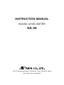
INSTRUCTION MANUAL
SOUND LEVEL METER
NA-28
3-20-41 Higashimotomachi, Kokubunji, Tokyo 185-8533, Japan
http://www.rion.co.jp/english/
Organization of the NA-28 Documentation
Documentation for the Sound Level Meter NA-28 comes in three parts, as
listed below.
Instruction Manual (this document)
Describes operating procedures for the Sound Level Meter NA-28, connection and use of peripheral equipment such as a level recorder and printer,
and use of the memory card.
Serial Interface Manual
Describes communication with a computer, using the serial interface built
into the Sound Level Meter NA-28. The manual covers the communication
protocol, use of control commands for the sound level meter, format of data
output by the sound level meter, and other topics.
Technical Notes
This document provides in-depth information about sound level meter
performance, microphone construction and characteristics, influence of
extension cables and windscreen on the measurement, and other topics.
* Company names and product names mentioned in this manual are usually
trademarks or registered trademarks of their respective owners.
i
ii
Organization of This Manual
This manual describes the features, operation and other aspects of the Sound Level
Meter NA-28 (with 1/3 octave analysis function). If the unit is used together with
other equipment to configure a measurement system, consult the documentation of
all other components as well. The following pages contain important information
about safety. Be sure to read and observe these in full.
This manual contains the following sections.
Outline
Gives basic information about the unit.
Controls and Functions
Briefly identifies and explains the operation keys and connectors and all
other parts of the unit.
Preparations
Explains how to check the unit before use and how to install and set up the
unit for measurement.
Calibration
Explains how to calibrate the unit for measurement.
Power On/Off
Explains how to operate the power switch of the unit.
Reading the Display
Explains symbols and other information shown on the display of the unit.
Measurement
Explains the basic procedures for measurement.
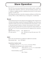
Store Operation
Explains how to store measurement data.
iii
Memory Card
Explains how to use a memory card with the unit.
Input/Output Connectors
Explains the input and output connectors of the unit.
Default Settings
Lists the factory default settings of the unit.
Setup File
Explains how to start up the unit using settings saved in a setup file.
Optional Accessories
Explains how to use the optional microphone extension cable, printer, and
level recorder with the unit.
Specifications
Lists the technical specifications of the unit.
iv
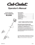
FOR SAFETY
In this manual, important safety instructions are specially marked as shown
below. To prevent the risk of death or injury to persons and severe damage
to the unit or peripheral equipment, make sure that all instructions are fully
understood and observed.
Caution
D isrega rd i ng i nst r uct ions
printed here incurs the risk of
injury to persons and/or damage to peripheral equipment.
Important
D isrega rd i ng i nst r uct ions
printed here incurs the risk of
damage to the product.
Note
Mentioned about the tips to
use this unit properly. (This
messages do not have to do
with safety.)
v
vi
Quantifier notation
(Sound level and sound pressure level are expressed uniformly as sound pressure level, distinguished by the use of frequency weighting.)
Display on
NA-28
Lp
Sound pressure
level
L eq
Equivalent
continuous
sound level
LE
Sound exposure
level
Lmax, Lmin
Maximum sound
level
LN
Percentile sound
level
Lpeak
Peak sound level
Ltm5
Takt-max sound
level(5sec)
Measurement value
the time weighting characteristics
F, S, 10 ms
I
A-weighted sound pressure level
LAF, LAS, LA10ms
LAI
C-weighted sound pressure level
LCF, LCS, LC10ms
(LCI)
Z-weighted sound pressure level
LZF, LZS , LZ10ms
(LZI)
Equivalent continuous A-weighted
sound level
LAeq
LAIeq
Equivalent continuous C-weighted
sound level
LCeq
(LCIeq)
Equivalent continuous Z-weighted
sound level
LZeq
(LZIeq)
A-weighted sound exposure level
LAE
(LAIE)
C-weighted sound exposure level
LCE
(LCIE)
Z-weighted sound exposure level
LZE
(LZIE)
Maximum A-weighted sound level
LAFmax, LASmax, LA10msmax
LAImax
Maximum C-weighted sound level
LCFmax, LCSmax, LC10msmax
(LCImax)
Maximum Z-weighted sound level
LZFmax, LZSmax, LZ10msmax
(LZImax)
Percentile A-weighted sound level
LAFNn, LASNn, LA10msNn
(LAINn)
Percentile C-weighted sound level
LCFNn, LCSNn, LC10msNn
(LCINn)
Percentile Z-weighted sound level
LZFNn, LZSNn, LZ10msNn
(LZINn)
A-weighted peak sound level
(LApeak)
---
C-weighted peak sound level
LCpeak
---
Z-weighted peak sound level
LZpeak
---
Takt-max A-weighted sound level(5sec)
LAtm5
---
Takt-max C-weighted sound level(5sec)
(LCtm5)
---
Takt-max Z-weighted sound level(5sec)
(LZtm5)
---
Note
The combination of peak sound pressure level and takt-max
with I characteristics does not exist.
Measurement value shown in brackets ( ) indicates items
that can be displayed as operation steps but are not used or
not suitable.
vii
viii
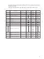
Quantifier Notation of Sound Level Meter NA-28 According to International
Standards and JIS
(Excerpts from ISO 1996, 3891, IEC 61672-1:2002, JIS Z 8202, 8731)
NA-28
nota tion
De s cription
Fre que ncy
we ighting
IS O
nota tion
IEC
nota tion
J IS
nota tion
LP
S ound le ve l
Z
Lp
Lp
LA
A-we ighte d s ound le ve l
A
Lp A
Lp A
LC
C-we ighte d s ound le ve l
C
LPeq
Equiva le nt continuous s ound
le ve l
Z
L Ae q
Equiva le nt continuous A-we ighte d
s ound le ve l
A
L Ce q
Equiva le nt continuous C-we ighte d
s ound le ve l
C
LPE
S ound e xpos ure le ve l
Z
L AE
A-we ighte d s ound e xpos ure le ve l
A
L CE
C-we ighte d s ound e xpos ure le ve l
C
LAe q,T
LAe q,T
LAe q,T
LCe q,T
LAE
L A05
LAE,T
LAE
LA5,T
LA5,T
LA10,T
LA10,T
LA50,T
LAN,T LA50,T
L A90
LA90,T
LA90,T
L A95
LA95,T
LA95,T
L A10
L AN L A50
P e rce ntile A-we ighte d s ound
le ve l
A
L Ama x
Ma ximum A-we ighte d s ound
le ve l
A
L Amin
Minimum A-we ighte d s ound
le ve l
A
L Cpk
C-we ighte d pe a k s ound le ve l
C
LAN,T
LCpe a k
ix
x
Precautions
Operate the unit only as described in this manual.
The NA-28 is a precision instrument. Protect it from shocks and vibrations.
Take special care not to touch the microphone diaphragm. The diaphragm
is a very thin metal film which can easily be damaged.
Use only the microphone/preamplifier assembly with the number as shown
on the name plate of the unit.
Ambient conditions for operation of the unit are as follows: temperature
range -10 to +50°C, relative humidity 10 to 90%RH.
Protect the unit from water, dust, extreme temperatures, humidity, and
direct sunlight during storage and use. Also keep the unit away from air
with high salt or sulphur content, gases, and stored chemicals.
Always turn the unit off after use. Remove the batteries from the unit if
it is not to be used for a long time (a week or more). When disconnecting
cables, always grasp the plug and do not pull the cable.
Before using the unit and before putting it away, always check that the
microphone grid has not become loose. If this has happened, refasten the
microphone grid firmly and then use or store the unit.
Clean the unit only by wiping it with a soft, dry cloth or, when necessary, with a cloth lightly moistened with water. Do not use any solvents,
cleaning alcohol or chemical cleaning agents.
Do not try to disassemble or alter the unit. Otherwise type certification
will become invalid. In case of an apparent malfunction, do not attempt
any repairs. Note the condition of the unit clearly and contact the supplier.
Do not tap the LCD panel or other surfaces of the unit with a pointed
object such as a pencil, screwdriver, etc.
Take care that no conductive objects such as wire, metal scraps, conductive plastics etc. can get into the unit.
xi
To ensure continued accuracy, have the unit checked and serviced at
regular intervals.
When using the unit for commercial purposes or for certification, official
certification is required every five years. Contact the supplier.
Dispose of the unit and of batteries only according to national and local
regulations at the place of use.
To conform to the EU requirement of the Directive
2002/96/EC on Waste Electrical and Electronic Equipment, the symbol mark on the right is shown on the
instrument.
xii
Contents
Organization of the NA-28 Documentation ..................................... i
Organization of This Manual ........................................................ iii
Outline ............................................................................................1
Controls and Functions ...................................................................3
Front View .................................................................................3
Microphone/Preamplifier .....................................................3
Display .................................................................................3
Operation key panel .............................................................4
Bottom View..............................................................................7
Rear View ..................................................................................8
Preparations ....................................................................................9
Power .........................................................................................9
AC adapter ......................................................................... 10
Windscreen (WS-10) ................................................................ 11
Diffuse Field Correction ..........................................................12
Tripod Mounting ......................................................................12
Memory Cards (CF Card) and Program Cards .........................13
Inserting a card ..................................................................13
Microphone Extension Cables (EC-04 series) .......................... 14
Connection to a Printer ............................................................ 16
Connection to a Level Recorder (LR-07, LR-20A) ................... 16
Connection to a Computer ....................................................... 17
Setting the Date and Time ....................................................... 18
Measurement in a dark location ............................................... 21
Sub Channel Settings ...............................................................22
Trigger Mode Settings .............................................................23
Sleep Mode ........................................................................26
Comparator Output ..................................................................30
About the comparator output .............................................. 31
Language Selection ..................................................................32
xiii
Calibration ....................................................................................33
Electrical calibration ..........................................................33
Power On/Off ................................................................................37
To turn the unit on ..............................................................37
To turn the unit off .............................................................38
Reading the Display ......................................................................39
Sound level meter mode screen ................................................39
Analyzer mode screen .............................................................44
T-L (Time/Level) display screen ..............................................44
Numeric display screen ............................................................45
Indicator messages ...................................................................46
Menu List Screen .....................................................................47
System ................................................................................47
Display ...............................................................................50
I/O (Input/Output) .............................................................. 51
Store ...................................................................................53
Measurement ......................................................................54
Print ...................................................................................56
Recall .................................................................................57
Measurement .................................................................................59
Sound Level Measurement .......................................................59
Sound level, sound pressure level .......................................59
Equivalent Continuous Sound Level (LAeq) Measurement... 61
Sound Exposure Level (LAE) Measurement ........................66
Maximum Sound Level (Lmax) and
Minimum Sound Level (Lmin) Measurement ....68
Selecting the Lmax /Lmin type ...............................................70
Percentile Sound Level (LN) Measurement ......................... 71
Additional Processing Value (Lpeak, LAtm5) Measurement ...73
Back-Erase Function...........................................................76
Marker ...............................................................................77
Max Hold ...........................................................................78
Delayed Measurement ........................................................79
xiv
Store Operation ............................................................................. 81
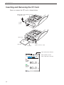
Inserting and Removing the CF Card ......................................84
Manual ....................................................................................85
Memory Store ....................................................................85
Auto1 ....................................................................................... 91
Auto2 .......................................................................................97
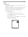
Memory Card ................................................................................99
Using a memory card .........................................................99
Input/Output Connectors ............................................................. 103
AC OUTPUT ......................................................................... 103
DC OUTPUT ......................................................................... 105
TRIG IN/COMP OUT jack .................................................... 106
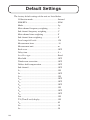
Default Settings ........................................................................... 108
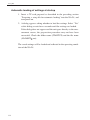
Setup File .................................................................................... 110
Preparing a setup file for automatic loading ..................... 111
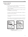
Saving a setup file .................................................................. 113
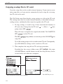
Copying a setup file to CF card .............................................. 114
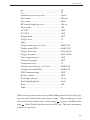
Optional Accessories ................................................................... 115
Microphone Extension Cables (EC-04 series) ........................ 115
Printer.................................................................................... 116
Level Recorder LR-07/LR-20A .............................................. 119
Program Cards ....................................................................... 121
Remote control ...................................................................... 122
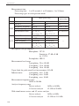
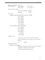
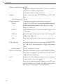
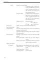
Specifications ..............................................................................124
xv
xvi
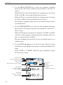
Outline
The Sound Level Meter NA-28 allows octave and 1/3 octave band analysis in
real time. It conforms to legal requirements for quantity measurements and to
JIS and IEC standards. It supports diffuse sound field measurements and also
meets standard requirements when the supplied windscreen is mounted.
The NA-28 consists of the 1/2-inch electret condenser microphone UC-59,
preamplifier NH-23, and the main unit. The main unit is equipped with an
LCD panel, operation keys, AC and DC output connector, USB port, comparator output, external trigger input, and infrared remote control sensor.
The unit supports real-time octave band analysis in the range from 16 Hz to
16 kHz, and real-time 1/3 octave band analysis in the range from 12.5 Hz to
20 kHz. It is also possible to perform octave and 1/3 octave band analysis
simultaneously. (In this case, the upper limit is 8 kHz for octave band and
12.5 kHz for 1/3 octave band.)
Measurement results are stored directly on a CompactFlash memory card
(called CF card in this manual).
Communication with a computer is possible via the built-in USB port. Because the USB port conforms to storage specifications, the NA-28 will be
recognized as a removable disk when connected to a computer. This allows
transfer of data from the CF card to the computer without having to remove
the CF card from the NA-28. USB host functionality is also provided, allowing the use of a USB printer.
The infrared remote control available as an option allows control of the
NA-28 without a cable link.
The comparator output is an open collector type, which can be used for
control of external equipment. Conversely, the trigger input allows control
of the NA-28 from another device.
Optional program cards for implementing architectural acoustics measurements and other types of measurement are also supported.
1
Outline
The Sound Level Meter NA-28 allows the following quantity measurements.
Main processing (sound level meter mode, analyzer mode)
Simultaneous measurement of all items with selected time weighting and
frequency weighting characteristics
Sound level
Lp
Equivalent continuous sound level
Leq
Sound exposure level
LE
Maximum sound level
Lmax
Lmin
LN (1 to 99) 1-increment steps,
max. 5 values, calculated from
Lp or Leq,1sec
In sound level meter mode, in addition to the main processing items, one
of the following measurements can be selected.
Peak sound level
Lpeak
Takt-max sound level
Ltm5
Minimum sound level
Percentile sound level
Frequency weighting characteristics are the same as for the sub
channel.
Frequency weighting characteristics
Time weighting characteristics
(main channel)
(sub channel)
A, C, Z
F, S, 10 ms
F, S, 10 ms, I
A color LCD with backlight shows measurement parameters and measurement values in sound level meter mode and analyzer mode.
The following options are available separately, to further enhance the range
of applications for the product.
Printer
For producing hard copy of measurement data (including stored
memory data).
Level recorder LR-07, LR-20A (No CE)
For recording sound level changes over time.
2
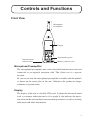
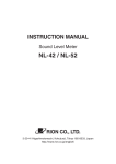
Controls and Functions
Front View
Microphone/
Preamplifier
SOUND LEVEL METER
1/3 OCTAVE BAND ANALYZER
NA-28
Display
START/STOP
STORE
PAUSE/CONT
MODE
GRP
NUM
4
MENU
+
LEVEL
SLM
RTA
ENT
-
CAL
LIGHT
Infrared remote
control sensor
3
1
2
POWER
Operation key panel
FREQ WEIGHT TIME
Memory card slot cover
Microphone/Preamplifier
The microphone/preamplifier unit can be detached from the main unit and
connected via an optional extension cable. This allows use at a separate
location.
Be sure to use only the microphone/preamplifier assembly with the number
as shown on the name plate of the unit. Otherwise the product no longer
conforms to specifications.
Display
The display of the unit is a backlit LCD panel. It shows the measured sound
level as a numeric indication and as a bar graph. It also indicates the operation status of the unit and shows measurement parameters as well as warning
indications and other information.
3
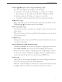
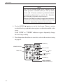
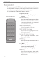
Controls and Functions
Operation key panel
START/STOP key
STORE key
MODE key
START/STOP
STORE
PAUSE/CONT
Key lock
PAUSE/CONT key
MODE
Indicator LED
GRP/NUM key
GRP
NUM
MENU
4
+
MENU key
SLM/RTA key
SLM
RTA
ENT
CAL key
CAL
-
LEVEL
LIGHT
LIGHT key
1
LEVEL
/
keys
3
2
FREQ WEIGHT TIME
/ / / keys
ENT key
POWER
POWER key
FREQ WEIGHT
/TIME WEIGHT keys
START/STOP key
Press to start or stop the measurement (including the various processing
functions).
STORE key
Serves to start the auto store process or to perform manual store for entering data into the memory.
MODE key
Switches the processing mode.
Each push of this key cycles through the results of the respective processing functions selected on the menu screens.
PAUSE/CONT key
During a measurement, this key can be used to exclude unwanted portions
from processing. Press the key to pause measurement, and press the key
again to resume measurement.
The back-erase function makes it possible to exclude data from an interval
of 5 seconds before the key was pressed from processing.
During pause, the indicator LED flashes in blue.
Indicator LED
Indicates the operation status of the unit by red, blue, and green flashing.
4
Controls and Functions
LEVEL
keys (Level range switching keys)
Serve for selecting the level range for measurement.
In sound level meter mode, the following six settings are available.
20 to 80, 20 to 90, 20 to 100, 20 to 110, 20 to 120, 30 to 130 dB
In analyzer mode, the following six settings are available.
-10 to 80, 0 to 90, 10 to 100, 20 to 110, 30 to 120, 40 to 130 dB
keys
These four keys serve for selecting and setting items on menu screens.
Holding the
keys down causes a fast change.
ENT key (Enter key)
Press this key to make or finalize the setting of an item in a menu or any
other setting.
When the key is pressed at the sound level measurement screen, the menu
list screen comes up.
POWER key
Turns power to the unit on and off. The key must be held down for at least
1 second to take effect.
FREQ WEIGHT/TIME WEIGHT keys
The FREQ WEIGHT key selects the frequency weighting characteristic.
The TIME WEIGHT key selects the time weighting characteristic.
The keys select the frequency weighting and time weighting characteristics
for the main channel. Frequency weighting and time weighting characteristics for the sub channel are selected using a MENU key.
LIGHT key
This key turns on the display backlight, for easier reading in a dark location. Press the key again to turn the backlight off.
When the automatic light out function was selected from the menu, the
backlight will turn itself off automatically after the preset time.
5
Controls and Functions
CAL key (Calibration key)
This key is used for calibration of the unit and for level calibration of
connected equipment.
SLM/RTA key (Sound level meter/Real-time analyzer key)
This key switches between sound level meter mode and real-time analyzer
mode.
MENU key
This key serves to bring up a menu screen for setting measurement parameters and making other settings. Pressing the key again closes the
menu.
GRP/NUM key (Graph/Numeric key)
This key switches the measurement screen between graphical and numeric
display.
Key lock
Pressing the GRP/NUM and MENU keys together activates the key lock.
A red lock symbol appears in the bottom left corner of the display, and
the operation keys except for the LIGHT key are disabled.
Pressing the GRP/NUM and MENU keys together once more cancels
the key lock.
To turn the unit off, you must first cancel the key lock and then hold down
the POWER key.
Memory card slot cover
Open this cover to insert or remove the CF card.
Infrared remote control sensor
Using an optional infrared remote control allows operation of the unit from
a distance.
6
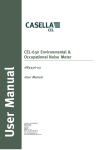
Controls and Functions
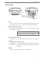
Bottom View
Cover
Bottom
External power supply jack
USB port
TRIG IN/COMP OUT jack
AC OUTPUT jack
DC OUTPUT jack
Cover
This cover protects the connectors on the bottom during transport or storage. Removing the cover gives access to the connectors shown above.
External power supply jack
The supplied AC adapter NC-94A can be connected here for powering
the unit from an AC outlet.
Important
To prevent the risk of damage, do not use any
AC adapter other than the specified type.
TRIG IN/COMP OUT jack
Allows input of an external trigger signal and output of a comparator
signal.
AC OUTPUT/DC OUTPUT jacks
AC OUTPUT: An AC signal with frequency weighting is output here.
DC OUTPUT: A DC signal corresponding to sound pressure level is
output here.
USB port
Serves for connection to a computer or a USB printer.
7
Controls and Functions
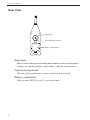
Rear View
Name plate
Tripod mounting thread
Battery compartment
Name plate
Shows various information including model number of the unit, microphone
number, preamplifier number, serial number, and date of manufacture.
Tripod mounting thread
The unit can be mounted on a camera tripod using this thread.
Battery compartment
Four batteries (IEC R14, size C) are inserted here.
8
Preparations
Power
The NA-28 can be powered by four IEC R14, size C batteries (alkaline or
manganese) or the AC adapter NC-94A.
Rechargeable batteries may also be used, but the NA-28 does not have a
facility for charging the batteries.
Note
When the AC adapter is connected, the unit will be
powered from the adapter, also when batteries are
inserted. (The AC adapter has priority.)
In case of a power failure or other interruption of AC
power, the unit will automatically switch to batter
power and continue to operate.
Inserting the batteries
1. Open the cover of the battery compartment as shown below.
2. Insert four IEC R14, size C batteries, paying attention to the polarity
as indicated in the compartment.
3. Replace the cover.
Push in the direction of
the arrow to open
Four IEC R14, size C batteries
(R14P, R14PU or LR14)
9
Preparations
Important
Take care not to reverse the (+) and (-) polarity
when inserting the batteries.
Always replace all four batteries together. To
prevent the risk of damage, do not mix old and
new batteries or batteries of different type.
To prevent the risk of battery fluid leakage, remove the batteries from the unit when the unit
is not used.
The life of a set of batteries depends on usage conditions and various other
factors. Some reference values are shown below.
Battery life (at 23°C) Alkaline batteries
LR14
16 hours
Manganese batteries
R14PU 6 hours
With alkaline batteries, keeping the display backlight continuously ON will result
in a battery life of 10 hours.
When additional processing is ON, battery life will be about 20 percent shorter.
Battery life may also be shorter when the optional filter is operating.
AC adapter
Connect the AC adapter as shown below.
Important
To prevent the risk of damage, do not use any
AC adapter other than the NC-94A.
External
power supply jack
AC
DC 5-6V
TRIG IN/
COMP OUT
DC
USB
OUTPUT
Open
cover on bottom
AC adapter NC-94A
To AC outlet, 100 to 240 V AC, 50/60 Hz
10
Preparations
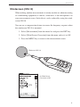
Windscreen (WS-10)
When making outdoor measurements in windy weather or when measuring
air conditioning equipment or similar, wind noise at the microphone can
cause measurement errors. Such effects can be reduced by using the windscreen WS-10.
You can use a compensation feature to ensure flat frequency response when
the windscreen WS-10 is mounted.
1. Select [Measurement] from the menu list and press the ENT key.
2. Select [Wind Screen Correction] from the menu and set it to ON.
3. Press the MENU key to return to the measurement screen.
Windscreen WS-10
Set Wind Screen
Correction to ON
Measurement menu screen
11
Preparations
Diffuse Field Correction
You can use a compensation feature to ensure flat frequency response in a
diffuse sound field.
1. Select [Measurement] from the menu list and press the ENT key.
2. Select [Diffuse Field Correction] from the menu and set it to ON.
3. Press the MENU key to return to the measurement screen.
Set Diffuse Field Correction
to ON
Measurement menu screen
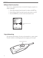
Tripod Mounting
For long-term measurements, the unit can be mounted on a camera tripod.
Proceed carefully, to avoid dropping the unit or tipping over the tripod.
Tripod mounting thread
12
Preparations
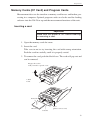
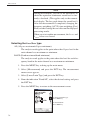
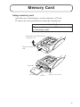
Memory Cards (CF Card) and Program Cards
Measurement data can be stored on a memory card for use and further processing in a computer. Optional program cards can also be used for loading
software into the NA-28 to expand the measurement functions of the unit.
Inserting a card
Important
Make sure that power is OFF before inserting
or removing a card.
1. Open the memory card slot cover.
2. Insert the card.
Take care to not to try inserting the card with wrong orientation.
Push the card in carefully, until it is properly seated.
3. To remove the card, push the black lever. The card will pop out and
can be removed.
Engage this section
with your nail to open the cover.
2
1. Slide
2. Lift
1
Front side
Lever
(push to remove card)
CF Card
Card slot
13
Preparations
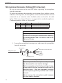
Microphone Extension Cables (EC-04 series)
Be sure to turn power to the unit OFF before separating the microphone
from the main unit.
To reduce measurement deviations due to refraction effects and the acoustic
influence of the operator, the microphone can be detached from the unit and
connected via an extension cable. Available cables are listed in the table
below. Cable runs of up to 35 meters are supported for standard compliance.
Combining multiple cables is also possible.
Type
Length
Type
Length
EC-04
EC-04A
EC-04B
2m
5m
10 m
EC-04C
EC-04D
EC-04E
30 m (reel) + 5 m (connection cable)
50 m (reel) + 5 m (connection cable)
100 m (reel) + 5 m (connection cable)
Important
With long extension cables, the cable capacitance restricts the upper measurement frequency
and measurement level. For details, refer to the
Technical Notes.
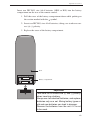
1. Loosen the preamplifier fastening screw and remove the preamplifier
from the main unit.
Microphone
Sound level meter main unit
Microphone grid
Preamplifier
Fastening screw
Important
Never separate the microphone and preamplifier, because this can lead to damage.
Before using the unit and before putting it away,
always check that the microphone grid has not
become loose. If this has happened, refasten
the microphone grid firmly and then use or store
the unit.
Never remove the microphone grid, because
this can lead to damage.
14
Preparations
2. Connect the extension cable to the preamplifier and to the main unit
and fasten the connectors with the fastening screw.
3. When mounting the microphone on a tripod, first fasten the microphone holder (supplied with the extension cable) to the tripod. Then
insert the extension cable connector into the microphone holder.
Preamplifier
Connector
Microphone
Microphone extension cable
Microphone holder
Tripod
15
Preparations
Connection to a Printer
The USB port on the bottom of the unit can be used for connection to a USB
printer, using the printer connection cable.
AC
DC 5-6V
DC
USB port
TRIG IN/
COMP OUT OUTPUT
USB
Open
cover on bottom
To printer
Printer connection cable
Connection to a Level Recorder (LR-07, LR-20A)
Sound level recording
Connect the AC OUTPUT jack on the bottom to a level recorder, as shown
below.
AC
DC 5-6V
TRIG IN/
COMP OUT
DC
USB
Open cover on bottom
OUTPUT
Connect
to AC OUTPUT
Output cable CC-24
To input connector
on level recorder LR-07, LR-20A
16
Preparations
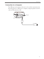
Connection to a Computer
The USB port on the bottom of the unit can be used for connection to the
RS-232C interface or USB port of a computer, using the optional serial I/O
cable or USB connection cable.
DC 5-6V
AC
DC
USB port
TRIG IN/
COMP OUT OUTPUT
USB
Open cover on bottom
To computer
17
Preparations
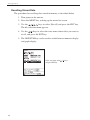
Setting the Date and Time
The NA-28 incorporates a clock which allows recording the date and time
along with measurement data.
Set the date and time as described below.
1. Press the POWER key to turn the unit on.
2. Press the MENU key. The menu list screen appears on the display.
3. Use the
keys to select [System] and press the ENT key.
4. Use the
keys to select [Time setting] and press the ENT
key.
5. Use the
keys to change the setting of the selected item.
6. Use the ENT key to switch to the next setting item [Year/Month/Day]
[Hour/Min/Sec].
7. Use the
keys to change the setting of the selected item. Press
the ENT key to terminate the setting. The clock starts moving with
the new setting.
8. Press the START/STOP key to return to the measurement screen.
Note
The clock IC used in this unit has an error of about
1 minute per month. Before measurement, be sure
to check and set the time if required.
START/STOP
STORE
PAUSE/CONT
MODE
GRP
NUM
4
MENU
+
MENU key
LEVEL
SLM
RTA
ENT
CAL
-
LIGHT
1
3
/ / /
ENT key
2
FREQ WEIGHT TIME
18
keys
POWER
POWER key
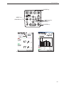
Preparations
Use / / / keys
to select [Time setting]
and press ENT key
System menu screen
Use / / / keys
to select item to set
Use ENT key to select digit
Use
/
keys to change value
Press ENT key to move on
Press ENT key to accept
System -- Time Setting screen
19
Preparations
Note
An internal rechargeable backup battery serves to
keep clock setting on the unit and to store measuring
data in internal memory. Those data and clock setting will be gone if the unit is not used for a certain
period or the backup battery is empty. The backup
battery is automatically charged by the main batteries
while the unit is operating. Full charge of the backup
battery requires approximate 24 hours.
For instance, the internal memory and clock setting is kept for 5 days when the backup battery is
charged for 5 hours. If the unit is not to be used for
an extended period, the main batteries should be
taken out to prevent possible damage due to battery
fluid leakage. After reinserting the batteries, be sure
to set the date and time.
20
Preparations
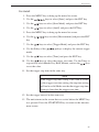
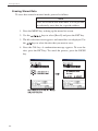
Measurement in a dark location
Pressing the LIGHT key will turn on the display backlight, for easier reading in a dark location. The backlight operation pattern can be controlled via
a menu, as follows.
1. Press the MENU key to bring up the menu list screen.
keys to select [I/O] and press the ENT key.
2. Use the
3. Use the
key.
keys to select [Backlight Brightness] and press the ENT
4. Use the
keys to select [Bright] or [Dark] and press the ENT key.
5. Use the
keys to select [Backlight Auto-Off] and press the ENT key.
6. Use the
ENT key.
keys to select the automatic turn-off interval and press the
START/STOP
STORE
PAUSE/CONT
MODE
GRP
NUM
4
MENU
+
MENU key
LEVEL
SLM
RTA
ENT
CAL
-
LIGHT
LIGHT key
1
3
2
POWER
FREQ WEIGHT TIME
/ / /
ENT key
keys
POWER key
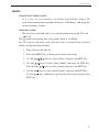
To turn the backlight off before the automatic turn-off point, press the LIGHT
key.
The [Bright] setting for backlight brightness will reduce battery life by about
50 percent, and the [Dark] setting by about 10 percent. When the backlight is
kept on continuously, battery life will be reduced to about 1/2.
Use / keys
to select
[Backlight Auto-Off]
Press ENT key
Use / keys
to select
[Backlight Brightness]
Press ENT key
is displayed
Bright
Dark is displayed
Use / keys
to select desired setting,
then press ENT key
Use / keys
to select desired setting,
then press ENT key
I/O menu screen
I/O menu screen
21
Preparations
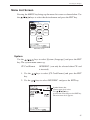
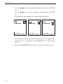
Sub Channel Settings
To use the sub channel, you must make certain settings on a menu screen.
1. Press the MENU key to bring up the menu list screen.
keys to select [Measurement] and press the ENT
2. Use the
key.
The measurement menu screen appears.
3. Use the
keys to select [Sub Channel] and press the ENT
key. The sub channel menu appears (next menu level).
4. Use the
keys to set [Sub Channel] to ON.
5. Set the required frequency weighting and time weighting characteristics.
6. Press the MENU key to return to the previous screen.
Press the START/STOP key to return to the measurement screen.
Select sub channel measurement
Display ON/OFF by pressing ENT
or key
Use / keys to select ON
Press ENT key
Set:
Frequency weighting
Time weighting
Lpeak/Ltm5
in the same way
Press
ENT key
Measurement menu screen
Sub Channel menu screen
Note
There is no frequency analysis function for the sub
channel. Only the all-pass value is measured.
22
Preparations
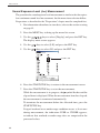
Trigger Mode Settings
The NA-28 offers a trigger mode whereby measurement is initiated by one
of three kinds of trigger: time trigger (time-controlled triggering), level trigger (sound level controlled triggering), and external trigger (triggering by an
external signal).
Time trigger: Measurement is controlled by a start time and stop time
setting.
Setting items
Trigger start time, trigger stop time
Trigger interval: OFF, 5, 10, 15, 30 (minutes), 1, 8, 24
(hours)
Sleep mode:
ON, OFF
Level trigger 1:
Measurement starts when trigger level is exceeded and
ends after a preset duration.
Setting items
Trigger level:
25 to 130 dB, 1-dB steps
Trigger bands: MAIN AP/SUB AP/12.5 Hz/16 Hz/20
Hz/25 Hz ... 20 kHz (1/3 octave
bands)
Slope:
+, Level trigger 2:
Single measurement is made when trigger level is exceeded.
Setting items
Trigger level:
25 to 130 dB, 1-dB steps
Trigger bands: MAIN AP/SUB AP/12.5 Hz/16 Hz/20
Hz/25 Hz ... 20 kHz (1/3 octave
bands)
External trigger:
Measurement starts at falling edge of logic-level signal
at external trigger connector.
23
Preparations
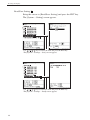
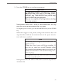
Time Trigger Setting
For Auto1
1. Press the MENU key to bring up the menu list screen.
2. Use the
keys to select [Store] and press the ENT key.
3. Use the
key.
keys to select [Store Mode] and press the ENT
4. Use the
keys to select [Auto1] and press the ENT key.
5. Press the MENU key to bring up the menu list screen.
6. Use the
keys to select [Measurement] and press the ENT
key.
7. Use the
key.
keys to select [Trigger Mode] and press the ENT
8. The current trigger mode setting is shown.
9. Use the
keys to select [Time] and press the ENT key.
10. Use the
keys to select the trigger start time. Use the
respectively select Month, Day, Hour, Minute, and use the
to set the value.
key to
keys
11. Set the trigger stop time in the same way.
12. The unit returns to the screen that was active before the MENU key
was pressed. Press the START/STOP key to return to the measurement screen.
24
Preparations
For Auto2
1. Press the MENU key to bring up the menu list screen.
2. Use the
keys to select [Store] and press the ENT key.
3. Use the
keys to select [Store Mode] and press the ENT key.
4. Use the
keys to select [Auto2] and press the ENT key.
5. Press the MENU key to bring up the menu list screen.
6. Use the
keys to select [Measurement] and press the ENT
key.
7. Use the
8. Use the
mode.
9. Use the
keys to select [Trigger Mode] and press the ENT key.
key of the
keys to display the current trigger
keys to select [Time] and press the ENT key.
10. Use the
keys to select the trigger start time. Use the
respectively select Month, Day, Hour, Minute, and use the
to set the value.
key to
keys
11. Set the trigger stop time in the same way.
Note
If the trigger stop time setting is the same or earlier
as the trigger start time setting, the stop time setting
will not be valid. Make sure that the trigger stop time
setting is later than the trigger start time.
12. Set the trigger interval in the same way.
13. The unit returns to the screen that was active before the MENU key
was pressed. Press the START/STOP key to return to the measurement screen.
25
Preparations
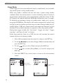
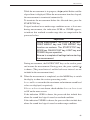
Sleep Mode
If time trigger has been selected for the Auto1 or Auto2 mode, you can enable
sleep mode (power-saving standby mode).
When sleep mode is enabled, the unit will enter a power-saving standby
condition before the measurement is started and during intervals between
measurements. In this mode, power consumption is reduced to about 1/3. The
LCD panel is off, and the indicator LED flashes in blue once every 5 seconds.
To check the measurement settings in standby mode, simply press any key
except the POWER key. The display will come on temporarily and will turn
itself off again if no further operation steps are taken. During standby, the AC
and DC outputs, USB port, remote control, and comparator functions are also
disabled. If one of these functions is required, set the sleep mode to OFF.
During time trigger standby, the "store name", "trigger start time", "trigger
stop time", and "Interval time" are shown.
If the sleep mode has been set to OFF, the unit will consume the normal
amount of power also during standby.
1. Select [Measurement] from the menu list and press the ENT key.
keys to select [Trigger Mode] from the menu and
2. Use the
press the ENT key.
3. Use the
keys to select [Time] and press the ENT key.
4. Use the
keys to select [Sleep Mode], set it to ON, and press the
ENT key.
5. Press the MENU key several times to return to the measurement
screen.
Select "Time"
as trigger mode
Trigger menu screen
26
Set sleep mode
to ON
Trigger menu screen
Preparations
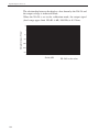
In the measurement standby condition, the indicator LED flashes in blue
using the following pattern.
0.1 second intervals
5 seconds
Lit Out Lit
Lit Out Lit
27
Preparations
Level Trigger Setting
1. Press the MENU key to bring up the menu list screen.
2. Use the
key.
3. Use the
keys to select [Measurement] and press the ENT
keys to select [Trigger Mode].
4. Use the
keys to select [Level*] and press the ENT key.
Level1: Measurement starts when trigger level is exceeded and ends
when preset measurement time has elapsed.
Level2: A single measurement is carried out when trigger level is
exceeded.
5. Use the
keys to select the trigger level, and use the
to set the value (25 to 130). Then press the ENT key.
keys
6. Use the same procedure to set the trigger band, and press the ENT
key.
7. When Level1 trigger is used, set the +/- slope. For Level2 trigger,
there is no slope setting.
When the setting is complete, press the ENT key.
8. The unit returns to the screen that was active before the MENU key
was pressed. Press the START/STOP key to return to the measurement screen.
28
Preparations
External Trigger Setting
1. Press the MENU key to bring up the menu list screen.
2. Use the
key.
keys to select [Measurement] and press the ENT
3. Use the
keys to select [Trigger Mode] and press the ENT key.
4. Use the
5. Use the
key to display the trigger mode.
keys to select [EXT.] and press the ENT key.
6. The unit returns to the screen that was active before the MENU key
was pressed. Press the START/STOP key to return to the measurement screen.
Trigger menu screen
29
Preparations
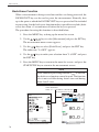
Comparator Output
This is an open collector output that can be used to control external equipment.
1. Press the MENU key to bring up the menu list screen.
keys to select [I/O(Input/Output)] and press the
2. Use the
ENT key.
3. The input/output menu is shown. Use the
keys to select [Com-
parator] and press the ENT key.
4. The I/O - Comparator menu appears.
4-1. Use the
keys to select [Comparator] and press the
key to display the ON/OFF setting. Use the
keys to select
ON and press the ENT key.
4-2. In the same way, select [Comparator Level], set the level, and
press the ENT key. (Setting range 25 to 130 dB, 1-dB steps)
4-3. In the same way, select [Comparator Band], set the band, and press
the ENT key. (SUB AP/MAIN AP/12.5 Hz/16 Hz/20 Hz/25 Hz
... 20 kHz, 1/3 octave bands)
5. Press the MENU key to return to the previous screen.
Press the START/STOP key to return to the measurement screen.
Press
ENT key
I/O (Input/Output) menu screen
30
Select comparator
Display ON/OFF by pressing ENT or
Use / keys to select ON
Press ENT key
Set
Comparator level
Comparator band
in the same way
I/O (Input/Output) Comparator screen
key
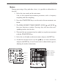
Preparations
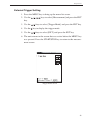
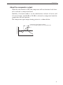
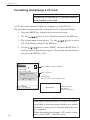
About the comparator output
When the sub channel is OFF, the comparator will not function if sub channel is selected as comparator band.
Similarly, if analyzer mode is set for simultaneous analysis of octave and
1/3 octave bands, and 16 kHz or 20 kHz is selected as comparator band, the
comparator will not function.
The comparator signal output timing pattern is as shown below.
Comparator level
Comparator signal output continues
for 1 second after signal crosses level threshold
1s
Time
31
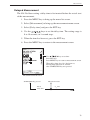
Preparations
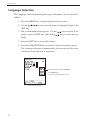
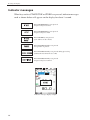
Language Selection
The language used for displaying messages and menus can be selected as
follows.
1. Press the MENU key to bring up the menu list screen.
2. Use the
ENT key.
keys to select [System (Language)] and press the
3. The system menu screen appears. Use the
guage], press the ENT key, and use the
guage.
keys to select [Lankeys to select the lan-
4. Press the ENT key to accept the setting.
5. Press the START/STOP key to return to the measurement screen.
The language selection is memorized by the unit and will be active
also the next time the unit is turned on.
Select language and press ENT key
Use MENU key
to return to measurement screen
System menu screen
32
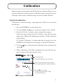
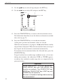
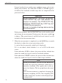
Calibration
Before starting a measurement, the NA-28 must be calibrated. There are two
types of calibration, namely electrical calibration using an internally generated signal and acoustic calibration using an external sound calibrator.
Electrical calibration
Calibration is carried out using a signal generator (1 kHz, sine wave) built
into the unit.
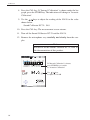
1. Press the POWER key to turn the unit on.
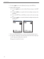
2. Use the LEVEL
keys to set the level range to 20 to 120 dB.
3. Press the CAL key. A display such as shown below appears.
If the level range setting is not 20 to 120 dB, a value of [level range
upper limit -6 dB] will be flashing instead of the ''114 dB'' indication
on the display.
If ''Acoustic Calibration'' is shown under the bar graph, press the
STORE key. The indication will change to ''Internal Calibration''.
4. Use the
keys to bring the level indication to the specified value
(114.0 dB).
5. When calibration to 114.0 dB is completed, press the CAL key once
more to return to the measurement screen.
Scale upper limit
"Internal Calibration" must be shown
If level range upper limit is not 120 dB,
[level range upper limit -6 dB] flashes here.
Use / keys to adjust
to [level range upper limit -6 dB]
(114.0 dB in this case)
33
Calibration
Scale upper limit
"Internal Calibration" must
be shown
If level range upper limit is
not 120 dB,
[level range upper limit -6 dB]
flashes here.
LCF
Use / keys to adjust
to [level range upper limit -6 dB]
(114.0 dB in this case)
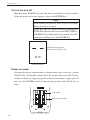
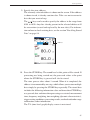
Signal output for calibration of external equipment
The normal level range setting for calibration is 30 to 120 dB, but for calibration of external equipment, another level range setting can also be chosen. In
this case, ''xx dB'' flashes on the calibration value indication.
The calibration value will always be 6 dB below the upper limit of the level
range setting.
Using the AC or DC output, calibration of connected equipment can be carried out as follows.
1. Press the CAL key.
2. Use the
keys to adjust the unit to the indicated level (maximum
value -6 dB).
A calibration signal is supplied at the AC OUTPUT and DC OUTPUT
jack on the bottom panel of the NA-28.
3. Press the CAL key once more to return to the measurement screen.
Note
General measurement law standard compliance applies to a sound level meter that has been electrically
calibrated with an internal signal.
During a measurement of a quantity other than sound
level (including when a triangle symbol is flashing
in the top left of the display, and when the unit is
in pause mode), calibration cannot be performed.
Perform calibration after measurement is completed
(START/STOP key has been pressed).
34
Calibration
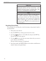
Acoustic calibration with Sound Calibrator NC-74
For acoustic calibration, a sound calibrator (pistonphone) is mounted to the
microphone of the sound level meter, and adjustment is performed so that the
reading of the meter is equal to the sound pressure level inside the coupler.
1. Turn off the Sound Calibrator NC-74.
2. Turn on the NA-28.
3. At the measurement screen, use the FREQ WEIGHT key to set frequency weighting for the main channel to ''A''.
4. Use the LEVEL
keys to set the level range to 30 to 120 dB.
5. Mount the 1/2-inch adapter on the coupler of the Sound Calibrator
NC-74.
1/2-inch adapter
for NC-74
Sound Calibrator NC-74
6. Insert the microphone very carefully and slowly all the way into the
coupler.
Important
Be very careful when inserting and removing
the microphone to and from the sound calibrator NC-74, to avoid a sudden pressure buildup
which could destroy the membrane of the microphone.
7. Set the power switch of the Sound Calibrator NC-74 to ON.
35
Calibration
8. Press the CAL key. If ''Internal Calibration'' is shown under the bar
graph, press the STORE key. The indication will change to ''Acoustic
Calibration''.
9. Use the
keys to adjust the reading of the NA-28 to the value
shown below.
Sound Calibrator NC-74: 94.0
10. Press the CAL key. The measurement screen returns.
11. Turn off the Sound Calibrator NC-74 and the NA-28.
12. Remove the microphone very carefully and slowly from the coupler.
Note
For details on the Sound Calibrator NC-74, refer to
the documentation of that product.
If "Internal Calibration" is shown,
press STORE key to switch
to "Acoustic Calibration"
Use / keys
to adjust to 94.0 dB
36
Power On/Off
To turn the unit on
Hold down the POWER key until the power-on screen appears (at least 1
second). When the screen is shown, release the POWER key. After the unit
has been initialized, the measurement screen appears.
During initialization, the indicator LED flashes blue green red.
START/STOP
STORE
PAUSE/CONT
MODE
Indicator LED
GRP
NUM
4
MENU
+
LEVEL
SLM
RTA
ENT
3
-
CAL
LIGHT
1
2
POWER
FREQ WEIGHT TIME
NA-28
POWER key
During initialization,
the "R" in the Rion logo
rotates.
SOUND LEVEL METER
1/3 OCTAVE BAND ANALYZER
IPL: 0.4.0085
CPU: 0.4.0085
Version 0.4
C RION
Co.,Ltd. All rights reserved.
Made in Japan
Power-on screen
37
Power On/Off
To turn the unit off
Hold down the POWER key until the unit is turned off (several seconds).
When the power-off screen appears, release the POWER key.
Note
After turning the unit off, wait at least 10 seconds
before turning it on again.
If the key lock has been activated, pressing the
POWER key has no effect. Press the GRP/NUM key
and MENU key simultaneously to cancel the key lock
condition, and then press the POWER key.
The Rion logo separates
into two parts and goes off.
Power-off screen
Power-on mode
Opening the battery compartment as shown below gives access to a switch
labeled ''A-B''. Setting this switch to the ''B'' position allows the NA-28 to be
turned on simply by supplying power to the external power supply jack. In
this case, the POWER switch on the operation panel of the NA-28 has no
effect.
A-B switch
Battery compartment
38
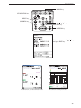
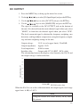
Reading the Display
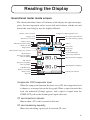
Sound level meter mode screen
The illustration below shows all elements of the display for explanation purposes. In actual operation, such a screen will not be shown, and the size and
font of the actual display may be slightly different.
Diffuse sound correction
Comparator ON/Comparator level
Trigger mode
Windscreen correction
Analyzer mode
Measurement time setting
Back-erase ON
Elapsed time
Measurement in progress symbol
Main channel
Frequency weighting
Time weighting
CF card insertion indicator
CF card remaining capacity
Address
Store mode
Level range
Bar graph
Overload indication
Under-range indication
Main channel level display
Sub channel
Frequency weighting
Time weighting
Sub channel level display
USB link status
Remote control ON
Battery status
Current date and time
Key lock
Comparator ON/Comparator level
When the comparator function has been set to ON, the comparator level
is shown as an orange line on the bar graph. When a signal exceeds that
level, the indication [Comp] appears, and a signal is output from the
COMP OUT jack on the bottom panel (open collector).
CF card insertion indicator
Shown when a CF card is inserted in the unit.
CF card remaining capacity
Shows the remaining capacity of an inserted CF card.
39
Reading the Display
Address
Shows the current memory address. In manual store mode, the indication
is red if there are data in that address. In Auto1 mode, the store cycle is
shown.
Store mode
Shows the selected mode for storing data in memory (Manual, Auto1, or
Auto2).
Level range
Shows the upper and lower limit of the bar graph. Can be switched with
the LEVEL
keys.
Bar graph
Shows the sound level as a bar graph indication. (The display is updated
every 100 ms.)
Overload indication
When a signal overload condition is detected, the indication
(white on
black) is shown for at least 1 second. If this indication appears frequently,
use the LEVEL
keys to increase the level range setting.
If processed data contain signal overload data, the indication
is
shown. This indication remains on the display until the next processing
measurement is started.
Under-range indication
When a signal under-range condition is detected, the indication
(white on black) is shown. If this indication appears frequently, use the
LEVEL
keys to decrease the level range setting.
If processed data contain signal under-range data, the indication
is
shown. This indication remains on the display until the next processing
measurement is started.
Main channel level display
Shows the measured sound level in the main channel. (The display is
updated every second.)
Sub channel level display
Shows the measured sound level in the sub channel. (The display is updated every second.)
40
Reading the Display
Current date and time
Shows the current date and time.
Key lock
Pressing the GRP/NUM key and MENU key simultaneously activates the
key lock condition and causes this symbol to appear. To cancel the condition, press the GRP/NUM key and MENU key once more together.
Battery status
When the unit is operated on battery power, you should regularly check
this indication. The number of black segments will decrease as the batteries get used up. When the indication starts to flash, replace the batteries
with a fresh set.
Blue
Batteries good
Blue
Blue
Batteries getting low
Red
Red
Indication flashes
Replace batteries
When the unit is being powered from an AC adapter, power plug symbol
( ) is shown.
Remote control ON
This indication is shown when remote control of the unit has been enabled.
USB link status
When the unit has been connected as a removable disk, this symbol is
shown in blue. When USB communication has been enabled, symbol is
shown in green.
Sub channel time weighting
Indicates the sub channel time weighting characteristic.
F: Fast, S: Slow, : 10 ms, I: Impulse
The sub channel time weighting characteristic is set from a menu.
Sub channel frequency weighting
Indicates the sub channel frequency weighting characteristic.
A: A-weighting, C: C-weighting, Z: Flat response
The sub channel frequency weighting characteristic is set from a menu.
41
Reading the Display
Main channel time weighting
Indicates the main channel time weighting characteristic.
F: Fast, S: Slow, : 10 ms
Main channel frequency weighting
Indicates the main channel frequency weighting characteristic.
A: A-weighting, C: C-weighting, Z: Flat response
Measurement in progress symbol
When a measurement is in progress, the symbol flashes. The indicator
LED also flashes in green.
During auto store, the symbol also flashes. The indicator LED flashes
in red.
During measurement standby, the symbol is shown.
During measurement pause, the symbol is shown. The indicator LED
flashes in blue.
Elapsed time
Shows the elapsed time in seconds during processing and during memory
store.
Back-erase ON
Indicates that the back-erase function has been set to ON.
Measurement time setting
Shows the measurement time that has been set with the menu. The available setting range is 1 sec (second) to 1000 h (hours).
Analyzer mode
Indicates the condition of the display screen.
SLM:
Sound level meter
OCT:
Octave band analyzer
1/3OCT:
1/3 octave band analyzer
OCT&1/3OCT:
Octave and 1/3 octave band analyzer
Windscreen correction
WS OFF] symbol is shown when windscreen correction is OFF.
[ WS ON] symbol is shown when windscreen correction is ON.
[
42
Reading the Display
Trigger mode
Controls the measurement and memory store start behavior. Available
modes are Level1, Level2, Time, and EXT.
Diffuse sound correction
Indicates that the unit has been set up for measurement in a diffuse sound
field.
43
Reading the Display
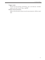
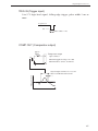
Analyzer mode screen
An example for the OCT & 1/3 OCT analysis screen is shown below.
keys to move to the target freUse the and keys of the
quency.
Comparator indication
Comparator band
Cursor
Main channel AP level
Sub channel AP level
Comparator level
Frequency and level
at cursor position
Analyzer mode screen
T-L (Time/Level) display screen
An example for the 1/3 OCT analysis screen is shown below.
AP
1/3oct 1 kHz Level in band selected
with cursor
20 seconds before
Current
Current measurement parameters
and level in main channel
T-L display screen
44
Reading the Display
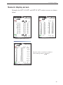
Numeric display screen
Examples for OCT, 1/3 OCT, and OCT·1/3 OCT analysis screens are shown
below.
Numeric display (OCT) screen
Numeric display (1/3 OCT) screen
Frequencies that are currently not displayed
can be called up with the / keys.
Numeric display (OCT, 1/3 OCT) screen
45
Reading the Display
Indicator messages
When keys such as START/STOP or STORE are pressed, indicator messages
such as shown below will appear on the display for about 1 second.
When START/STOP key was pressed
and processing has started
When START/STOP key was pressed
and processing has ended
When STORE key was pressed
(store address is also shown)
When PAUSE/CONT key was pressed
and operation is paused
When PAUSE/CONT key was pressed during processing
(with back-erase function set to ON)
When PAUSE/CONT key was pressed
and processing has resumed
Indicator message display example
46
Reading the Display
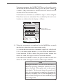
Menu List Screen
Pressing the MENU key brings up the menu list screen as shown below. Use
keys to select the desired menu and press the ENT key.
the
Menu list screen
System
Use the
keys to select [System (Language)] and press the ENT
key. The system menu comes up.
CF Card Format
OFF/EXEC. (can only be selected when CF card
is inserted)
1. Use the
keys to select [CF Card Format] and press the ENT
key.
2. Use the
keys to select OFF/EXEC. and press the ENT key.
Symbol shows that
a lower menu level exists.
Use / / / keys
to select the item and press the ENT key.
The next menu level appears.
System menu screen
47
Reading the Display
Read/Save Setting
Bring the cursor to [Read/Save Setting] and press the ENT key.
The [System -- Setting] screen appears.
Return
MENU
Use / / / keys to select the item and press the ENT key.
The [System -- Settings -- Save] screen appears.
Use / / / keys to select the item and press the ENT key.
The [System -- Settings -- Load] screen appears.
48
Reading the Display
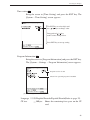
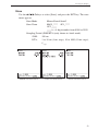
Time setting
Bring the cursor to [Time Setting] and press the ENT key. The
[System -- Time Setting] screen appears.
Use ENT key to select digit and
use
/ keys to change value
Long push of / key
makes values change faster
Press ENT key to accept setting
[System -- Time Setting] screen
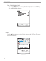
Program Information
Bring the cursor to [Program Information] and press the ENT key.
The [System -- Settings -- Program Information] screen appears.
Program version of unit
Shown if an optional program is installed
[System -- Program Information] screen
Language 日本語/English/Deutsch/Español/French(Refer to page 32)
CF size
** MByte: Shows the remaining free space on the CF
card.
49
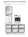
Reading the Display
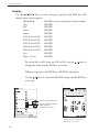
Display
Use the
keys to select [Display] and press the ENT key. The
display menu screen appears.
MAX Hold
ON/OFF (can be selected in analyzer mode)
Leq
ON/OFF
LE
ON/OFF
Lmax
ON/OFF
Lmin
ON/OFF
LN1 (L01 to L99)
ON/OFF
LN2 (L01 to L99)
ON/OFF
LN3 (L01 to L99)
ON/OFF
LN4 (L01 to L99)
ON/OFF
LN5 (L01 to L99)
ON/OFF
List
ON/OFF
Time - Level
ON/OFF
To set the L01 to L99 value for LN1 to LN5, use the
change the value and the ENT key to accept.
keys to
When you next press the ENT key, ON/OFF is displayed.
Use the
keys to select the ON/OFF setting, and the ENT key
to accept.
Setting range L01 to L99
Set percentile sound level
LN required for
measurement to ON
Display menu screen
50
List display example
Shown when switching mode
with "List" set to ON
Reading the Display
I/O (Input/Output)
Use the
keys to select [I/O (Input/Output)] and press the ENT
key. The Input/Output menu screen appears.
AC Out
OFF/MAIN/SUB
DC Out
OFF/MAIN/SUB
Comparator
ON/OFF
USB Communication ON/OFF
Remote Control
ON/OFF
Backlight Brightness Dark/Bright
Backlight Auto-Off 30 s/3 m/Cont
Beep
ON/OFF
Index
1 to 255 (a number for identifying the unit when
multiple units are used in a parallel measurement setup)
Press the ENT key to display ON/OFF/etc. Use the
keys to
select ON/OFF/etc. and press the ENT key.
When beep tones are set to ON, a long beep will be heard at the
end of a measurement and a short and long beep when a store
operation is complete.
Input/Output menu screen
51
Reading the Display
Comparator menu level
Use the
keys to select [Comparator] and press the ENT key.
The following menu appears.
Comparator
ON/OFF
Comparator Level
25 to 130 dB (1-dB steps)
Comparator Band
SUB AP/MAIN AP/12.5 Hz/16 Hz/20 Hz/25 Hz
... 20 kHz, 1/3 octave bands)
Input/Output -- Comparator menu screen
Comparator
setting band
52
Comparator
setting level
Reading the Display
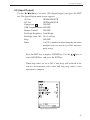
Store
Use the
keys to select [Store] and press the ENT key. The store
menu appears.
Store Mode
Manual/Auto1/Auto2
Store Name
MAN_**** AU1_****
AU2_****
**** is a 4-digit number from 0000 to 9999
Sampling Period (SLM/RTA) (only shown in Auto1 mode)
SLM:
100 ms
RTA:
1 to 10 ms (1-ms steps), 10 to 1000 (10-ms steps),
Leq,1s
Manual store menu screen
Auto1 store menu screen
Auto2 store menu screen
53
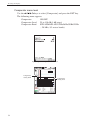
Reading the Display
Measurement
Use the
keys to select [Measurement] and press the ENT key.
The measurement menu appears.
Wind Screen Correction
ON/OFF
Measurement Time Auto1 1 s to 1000 h
Auto2 (normal measurement) 1 s to 24 h
Back-Erase
OFF/5 s
Delay Time
1 to 10 s
Lmax/Lmin Type
BAND/AP (can be selected only in analyzer
mode)
OFF
Trigger Mode
Diffuse Field Correction
ON/OFF
Sub Channel
ON/OFF
LN Mode
Lp
Measurement menu screen
54
Reading the Display
Trigger mode menu level
Use the
keys to select [Trigger Mode] and press the ENT key.
The following menu appears.
Available trigger mode settings are Level 1, Level 2, Time, and EXT.
It is available
to set the trigger
interval when the
store mode is
Auto 2
Measurement-Trigger screen
Level 1
Setting items
Trigger level
Trigger band
Slope:
Level 2
Setting items
Trigger level
Trigger band
25 to 130 dB, 1-dB steps
MAIN AP/SUB AP/12.5 Hz/16 Hz/20 Hz/25 Hz ...
20 kHz, 1/3 octave bands)
+, -
25 to 130 dB, 1-dB steps
MAIN AP/SUB AP/12.5 Hz/16 Hz/20 Hz/25 Hz ...
20 kHz, 1/3 octave bands)
Time
Setting items
Trigger start time, trigger stop time
Interval time:
OFF, 5, 10, 15, 30 (minutes), 1, 8, 24 (hours)
Sleep mode:
ON, OFF
EXT.
Select this to use an external trigger.
55
Reading the Display
Sub channel menu level
Use the
keys to select [Sub Channel] and press the ENT key.
The following menu appears.
Measurement-SUB Chnnel
Measurement-SUB Chnnel screen
Print
Use the
keys to select [Print] and press the ENT key. The print
menu screen appears.
Printing screen
56
Reading the Display
Recall
Use the
keys to select [Recall] and press the ENT key. The Select
File menu appears.
Select File menu screen
57
Reading the Display
Menu List Items
System
CF Card Format
Read/Save Settings [v]---------- Load Default
Group Save for CF card [v]---------------- List of setting groups on CF card
Group Loading/Delete for CF card [v]---- List of setting groups on CF card
Time Setting
----------------Year/Month/Day Hour:Min:Sec
Program Information [v]----------------- Model, Version
Language
CF size
Display
MAX Hold, Leq, LE, Lmax, Lmin, LN1, LN2, LN3, LN4, LN5, List, Time - Level
I/O(Input/Output)
AC OUT
DC OUT
Comparator [v]------------------- Comparator ON/OFF, Comparator Level, Comparator Band
USB Communication
Remote Control
Backlight Brightness
Backlight Auto-Off
Beep
Index
Store
Store Mode
Store Name
Sampling Period (SML/RTA)*
Measurement
Windscreen Correction
Measurement Time
Back-Erase
Delay Time
Lmax/Lmin Type
Trigger Mode [v]----------------- OFF, Level 1, Level 2, Time, EXT.
Diffuse Field Correction
Sub Channel [v]------------------ Sub channel measurement ON/OFF, frequency weighting,
time weighting, Lpeak/Ltm5
Print
Enable/disable screen content printout
Recall
Recall data list
[v]------: Items displayed when proceeding to next menu level
* Sampling Period
SLM mode: 100 ms
RTA mode: 1 to 10 ms (1-ms steps), 10 to 1000 (10-ms steps), Leq,1s
58
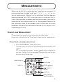
Measurement
When using the NA-28 in a mode other than "sound level measurement", all
processing functions provided by the unit (Leq, LE , Lmax, Lmin, LN) are carried out simultaneously. (However, for the sub channel, only the additional
processing function set to "ON" in the menu screen is carried out.) For example, when equivalent continuous sound level measurement is selected, the
sound exposure level and percentile level are also determined. However, the
time percentage setting for the percentile level (5 values) must be selected
beforehand. Also, make sure that the date and time are set correctly, as described on page 18 to 19.
Sound Level Measurement
The procedure for sound level measurement is described below.
Preparations as described in the "Preparations" chapter must be completed fi rst.
Sound level, sound pressure level
1. Press the POWER key to turn the unit on.
After the power-on screen has been shown, the measurement screen
appears.
The measurement parameter settings depend on the condition the
unit was in before it was last turned off. Therefore the actual display
may not always be the same.
MODE key
START/STOP
STORE
PAUSE/CONT
START/STOP key
MODE
Indicator LED
GRP
NUM
4
MENU
+
MENU key
LEVEL
SLM
RTA
ENT
CAL
-
LIGHT
1
LEVEL
/
keys
3
2
FREQ WEIGHT TIME
/ / /
ENT key
keys
POWER
POWER key
FREQ WEIGHT/
TIME WEIGHT keys
59
Measurement
2. Use the FREQ WEIGHT key to select the frequency weighting
characteristic. For normal sound level measurements, select the "A"
setting.
When LZ (Flat) is selected for display, the sound pressure level from
10 Hz to 20 kHz is measured with flat characteristics.
When LC (Flat) is selected for display, the sound pressure level from
31.5 Hz to 8 kHz is measured with flat characteristics.
The frequency weighting characteristic for the sub channel must be
set with the menu.
3. Use the TIME WEIGHT key to select the time weighting (dynamic)
characteristics. For normal sound level measurements, select the "F"
(Fast) setting.
When performing measurements in compliance with IEC or another
standard, set the frequency weighting and time weighting characteristics as required by that standard.
The time weighting characteristic for the sub channel must be set
with the menu.
4. Use the LEVEL
keys to set the level range. Choose a setting
in which the bar graph indication registers to about the middle of the
range.
If the "OVER" or "UNDER" indicators appear frequently, change
the level range setting.
Analyzer mode
Measurement time setting
Back-erase ON
Elapsed time
Measurement in progress symbol
Main channel
Frequency weighting
Time weighting
Sub channel
Frequency weighting
Time weighting
60
Bar graph
UNDER
OVER
OVER
Overload indication
UNDER
Under-range indication
Measurement
5. The level indication shows the currently measured sound level (sound
pressure level). The reading is updated once every second.
The PAUSE/CONT key can be used to stop and resume the updating of level indication. In sound level meter mode, the bar graph
indication will be updated also during pause. In the pause condition,
a pause symbol ( ) appears on the display, and the indicator LED
flashes blue.
Important
During sound level measurement, do not press
the MODE key. Otherwise other processing
results will be shown.
The sound level is being displayed when there is
no character string after the basic indication.
LF:
Sound level is being displayed
LAeq:
Sound level is not being displayed
Note
If you press FREQ WEIGHT key, TIME WEIGHT
key, or LEVEL
keys during measurement,
the indication [Marker- *] appears and the keypress
has no effect.
Equivalent Continuous Sound Level (LAeq) Measurement
The procedure for equivalent continuous sound level measurement is described below.
Preparations as described in the "Preparations" chapter must be completed
first.
1. Turn power to the unit on.
2. Use the FREQ WEIGHT key to select the frequency weighting characteristic.
For normal measurements, select "A" (A-weighting).
When "C" (C-weighting) is selected, the equivalent continuous sound
pressure level (LCeq) is measured.
3. Use the TIME WEIGHT key to select the time weighting (dynamic
characteristics). Normally, select the "F" (Fast) setting.
61
Measurement
Note
The NA-28 performs high-speed sampling of the
sound pressure waveform (15.6 µs; 20.8 µs when
octave and 1/3 octave analysis is performed simultaneously) to determine Leq and LE. It is therefore
not affected by dynamic characteristics.
However, the Impulse setting for equivalent continuous
sound level measurement in the additional processing
function is affected by dynamic characteristics.
4. Use the LEVEL
keys to set the level range. Choose a setting
in which the bar graph indication registers to about the middle of the
range.
If the "OVER" or "UNDER" indicators appear frequently, change
the level range setting.
5. For information about how to store data, refer to the section starting
on page 81.
MODE key
START/STOP
STORE
PAUSE/CONT
START/STOP key
MODE
Indicator LED
GRP
NUM
4
MENU
+
MENU key
LEVEL
SLM
RTA
ENT
CAL
-
LIGHT
1
LEVEL
/
keys
3
2
FREQ WEIGHT TIME
/ / /
ENT key
keys
POWER
POWER key
FREQ WEIGHT/
TIME WEIGHT keys
62
Measurement
6. Set the measurement time from the menu.
Press the MENU key to bring up the menu list screen.
7. Use the
keys to select [Measurement] and press the ENT
key.
The measurement menu screen appears.
8. Use the
keys to select [Measurement time] and press the ENT
key.
9. Use the
keys to set the measurement time and the unit and press
the ENT key.
Set measurement time
When a delay time is set here,
measurement will start xx seconds
after START/STOP key is pressed.
Measurement menu screen
Measurement start
START/STOP key pressed
Preset
delay time
Leq time
Time
Time graph for delay time
START/STOP key pressed
Trigger event
Trigger standby
Preset
delay time
Measurement start
Leq time
Time
Time graph for use of trigger function
10. Press the MENU key to return to the menu list screen and use the
keys to select [Display]. Press the ENT key. The display
menu screen appears.
63
Measurement
11. Use the
keys to select [Leq] and press the ENT key.
12. Use the
keys to select ON and press the ENT key.
Set Leq to ON
Display menu screen
13. Press the START/STOP key to return to the measurement screen.
For information about how to use the back-erase function to exclude
data, refer to page 76.
14. Press the START/STOP key to start the measurement.
At this point, previous measurement values are cleared.
While the measurement is in progress, the symbol flashes and the
elapsed time is displayed. When the measurement time set in step 9
has elapsed, the measurement is terminated automatically.
To terminate the measurement before the allocated time, press the
START/STOP key.
If signal overload or an under-range condition occurs at least once
during measurement, the indication OVER or UNDER appears,
to indicate that overload or under-range data are comprised in the
processed values.
Important
During measurement, the LEVEL
keys,
FREQ WEIGHT key, and TIME WEIGHT key
function as markers. The START/STOP key,
MODE key, PAUSE/CONT key, LIGHT key, and
POWER key are operative.
Be sure to complete all settings before starting
the measurement.
64
Measurement
During measurement, the PAUSE/CONT key can be used to pause
and resume the measurement. During pause, the pause symbol ( )
is shown. (The paused interval and the back-erase interval are not
included in the measurement time.)
If the back-erase function was enabled in steps 7 and 8, using the
Time-Level screen is convenient. Data excluded by the back-erase
function are indicated on the display as follows.
Data excluded
by back-erase function
Time-Level screen
15. When the measurement is completed, use the MODE key to switch
the display to show the various processing results.
LAeq means that the equivalent continuous sound level is displayed.
If LAeq is not shown, check whether Leq is set to ON on the menu screen.
If the indication OVER is shown, the processed data include data
where the sound level signal caused an overload condition.
If the indication UNDER is shown, the processed data include data
where the sound level signal caused an under-range condition.
Note
During measurement, you can use the MODE key to
check the equivalent continuous sound level as currently calculated. (This applies only to the numeric
level display. The bar graph shows the sound level.)
After the measurement is completed, changing the
frequency weighting (A/C/Z), time weighting (Fast/
Slow) or other settings has no effect on the displayed
processing results.
65
Measurement
Sound Exposure Level (LAE) Measurement
The procedure for sound exposure level measurement is similar to that for equivalent continuous sound level measurement, but the menu item selection differs.
Preparations as described in the "Preparations" chapter must be completed fi rst.
1. For information about how to store data, refer to the section starting
on page 81.
2. Press the MENU key to bring up the menu list screen.
keys to select [Display] and press the ENT key.
3. Use the
The display menu screen appears.
4. Use the
keys to select [LE] and press the ENT key.
5. Use the
keys to select ON and press the ENT key.
Set LE to ON
Display menu screen
6. Press the START/STOP key to return to the measurement screen.
7. Press the START/STOP key to start the measurement.
While the measurement is in progress, the symbol flashes and the
elapsed time is displayed. When the measurement time has elapsed,
the measurement is terminated automatically.
To terminate the measurement before the allocated time, press the
START/STOP key.
If signal overload or an under-range condition occurs at least once
during measurement, the indication OVER or UNDER appears,
to indicate that overload or under-range data are comprised in the
processed values.
66
Measurement
Important
During measurement, the LEVEL
keys,
FREQ WEIGHT key, and TIME WEIGHT key
function as markers. The START/STOP key,
MODE key, PAUSE/CONT key, LIGHT key, and
POWER key are operative.
Be sure to complete all settings before starting
the measurement.
During measurement, the PAUSE/CONT key can be used to pause
and resume the measurement. During pause, the pause symbol ( )
is shown. (The paused interval and the back-erase interval are not
included in the measurement time.)
8. When the measurement is completed, use the MODE key to switch
the display to show the various processing results.
LAE means that the sound exposure level is displayed.
If LAE is not shown, check whether LAE is set to ON on the menu
screen.
If the indication OVER is shown, the processed data include data
where the sound level signal caused an overload condition.
If the indication UNDER is shown, the processed data include data
where the sound level signal caused an under-range condition.
Note
During measurement, you can use the MODE key
to check the equivalent continuous sound level as
currently calculated. (This applies only to the numeric level display. The bar graph shows the sound
level.)
After the measurement is completed, changing the
frequency weighting (A/C/Z), time weighting (Fast/
Slow) or other settings has no effect on the displayed
processing results.
67
Measurement
Maximum Sound Level (Lmax) and Minimum Sound Level
(Lmin) Measurement
The procedure for maximum sound level and minimum sound level measurement is similar to that for equivalent continuous sound level measurement,
but the menu item selection differs.
Preparations as described in the "Preparations" chapter must be completed fi rst.
1. For information about how to store data, refer to the section starting
on page 81.
2. Press the MENU key to bring up the menu list screen.
keys to select [Display] and press the ENT key.
3. Use the
The display menu screen appears.
4. Use the
keys to select [Lmax] and press the ENT key.
5. Use the
keys to select ON and press the ENT key.
6. Use the
keys to select [Lmin] and press the ENT key.
7. Use the
keys to select ON and press the ENT key.
Note
To measure Lmax only, verify that Lmin is set to OFF
and skip steps 6 and 7.
To measure Lmin only, verify that Lmax is set to OFF
and skip steps 4 and 5.
8. Press the MENU key to return to the measurement screen.
9. Press the START/STOP key to start the measurement.
Set Lmax
to ON
Display menu screen
68
Set Lmin
to ON
Measurement
While the measurement is in progress, the symbol flashes and the
elapsed time is displayed. When the measurement time has elapsed,
the measurement is terminated automatically.
To terminate the measurement before the allocated time, press the
START/STOP key.
If signal overload or an under-range condition occurs at least once
during measurement, the indication OVER or UNDER appears,
to indicate that overload or under-range data are comprised in the
processed values.
Important
During measurement, the LEVEL
keys,
FREQ WEIGHT key, and TIME WEIGHT key
function as markers. The START/STOP key,
MODE key, PAUSE/CONT key, LIGHT key, and
POWER key are operative.
Be sure to complete all settings before starting
the measurement.
During measurement, the PAUSE/CONT key can be used to pause
and resume the measurement. During pause, the pause symbol ( )
is shown. (The paused interval and the back-erase interval are not
included in the measurement time.)
10. When the measurement is completed, use the MODE key to switch
the display to show the various processing results.
LAmax and LAmin mean that the maximum and minimum sound level
values are displayed, respectively.
If LAmax or LAmin is not shown, check whether LAmax or LAmin is set
to ON on the menu screen.
If the indication OVER is shown, the processed data include data
where the sound level signal caused an overload condition.
If the indication UNDER is shown, the processed data include data
where the sound level signal caused an under-range condition.
69
Measurement
Note
During measurement, you can use the MODE key to
check the equivalent continuous sound level as currently calculated. (This applies only to the numeric
level display. The bar graph shows the sound level.)
After the measurement is completed, changing the
frequency weighting (A/C/Z), time weighting (Fast/
Slow) or other settings has no effect on the displayed
processing results.
When you start another measurement, the LAmax and
LAmin values are cleared.
Selecting the Lmax /Lmin type
AP (All-pass maximum/all-pass minimum):
The analysis result applies to the point where the all-pass level in the
main channel was maximum or minimum.
BAND (Band maximum/band minimum)
The analysis result applies to the point where the level for each frequency band in the main channel was maximum or minimum.
1. Press the MENU key to bring up the main menu.
2. Select [Measurement] and press the ENT key. The measurement
menu screen appears.
3. Select [Lmax/Lmin Type] and press the ENT key.
4. From the indication "Band/AP", select the desired setting and press
the ENT key.
5. Press the MENU key to return to the measurement screen.
Select Lmax/Lmin type
Press ENT key
Select Band/AP
Press ENT key
Measurement menu screen
70
Measurement
Percentile Sound Level (LN ) Measurement
The procedure for percentile sound level measurement is similar to that for equivalent continuous sound level measurement, but the menu item selection differs.
Preparations as described in the "Preparations" chapter must be completed fi rst.
1. For information about how to store data, refer to the section starting
on page 81.
2. Press the MENU key to bring up the menu list screen.
3. Use the
keys to select [Display] and press the ENT key.
The display menu screen appears.
4. Use the
keys to select [LN] and press the ENT key.
In the factory default condition, the percentile sound level values for
measurement are L05, L10, L50, L90, and L95. However, any value
from L01 to L99 can be chosen (up to five values).
Use the
keys to select the ON setting and press the ENT key.
5. Press the START/STOP key to return to the measurement screen.
Settings from L01 to L99 are possible
Set required percentile
sound level values to ON
Display menu screen
6. Press the START/STOP key to start the measurement.
While the measurement is in progress, the symbol flashes and the
elapsed time is displayed. When the measurement time has elapsed,
the measurement is terminated automatically.
To terminate the measurement before the allocated time, press the
START/STOP key.
When “no display” (arbitrary measurement time) has been selected, the
measurement is also stopped by pressing the START/STOP key.
71
Measurement
If signal overload or an under-range condition occurs at least once
during measurement, the indication OVER or UNDER appears,
to indicate that overload or under-range data are comprised in the
processed values.
Important
During measurement, the LEVEL
keys,
FREQ WEIGHT key, and TIME WEIGHT key
function as markers. The START/STOP key,
MODE key, PAUSE/CONT key, LIGHT key, and
POWER key are operative.
Be sure to complete all settings before starting
the measurement.
During measurement, the PAUSE/CONT key can be used to pause
and resume the measurement. During pause, the pause symbol ( )
is shown. (The paused interval and the back-erase interval are not
included in the measurement time.)
7. When the measurement is completed, use the MODE key to switch
the display to show the various processing results.
LN means that the percentile sound level is displayed.
If LN is not shown, check whether LN is set to ON on the menu
screen.
If the indication OVER is shown, the processed data include data
where the sound level signal caused an overload condition.
If the indication UNDER is shown, the processed data include data
where the sound level signal caused an under-range condition.
Note
During measurement, you can use the MODE key
to check the equivalent continuous sound level as
currently calculated. (This applies only to the numeric level display. The bar graph shows the sound
level.)
After the measurement is completed, changing the
frequency weighting (A/C/Z), time weighting (F/S)
or other settings has no effect on the displayed processing results.
72
Measurement
Additional Processing Value (Lpeak , LAtm5 ) Measurement
When the NA-28 is in sound level meter mode and the sub channel is ON,
the following processing functions are available in addition to Leq, LE , Lmax,
Lmin, and LN.
Lpeak:
LAtm5:
Peak sound level
Time-weighted takt-max sound level
The peak sound pressure level is based on the sound pressure waveform peak
level before being smoothed by time weighting.
Lpeak is the peak level with flat characteristics and LCpeak the peak level with
C-weighting.
The time-weighted takt-max sound level LAtm5 is the power average of the
maximum level for each 5-second interval.
Preparations as described in the "Preparations" chapter must be completed fi rst.
1. Turn power to the unit on.
Use the FREQ WEIGHT key to select the frequency weighting
characteristic.
2. Set the measurement time from the menu.
Press the MENU key to bring up the main menu screen.
3. Use the
keys to select [Measurement] and press the ENT key.
The measurement menu screen appears.
4. Use the
key or the
5. Use the
keys to select [Measurement Time] and press the ENT
key.
keys to set the measurement time and the unit and press
the ENT key.
For information about how to use the back-erase function to exclude
data, refer to page 76.
Note
The NA-28 has a pause function and a back-erase
function that allows excluding data for the immediately preceding 5 seconds from the measurement.
However, the back-erase function cannot be used
when LAtm5 is selected.
73
Measurement
6. Select Lpeak /Ltm5.
7. Press the START/STOP key to return to the measurement screen.
8. Use the LEVEL
keys to set the level range. Choose a setting
in which the bar graph indication registers to about the middle of the
range.
If the "OVER" or "UNDER" indicators appear frequently, change
the level range setting.
9. Press the START/STOP key to start the measurement.
While the measurement is in progress, the symbol flashes and the
elapsed time is displayed. When the measurement time has elapsed,
the measurement is terminated automatically.
To terminate the measurement before the allocated time, press the
START/STOP key.
The START/STOP key is also used to stop the measurement when
MANUAL has been selected. If signal overload or an under-range
condition occurs at least once during measurement, the indication
OVER or UNDER appears, to indicate that overload or under-range
data are comprised in the processed values.
Important
During measurement, the LEVEL
keys,
FREQ WEIGHT key, and TIME WEIGHT key
function as markers. The START/STOP key,
MODE key, PAUSE/CONT key, LIGHT key, and
POWER key are operative.
Be sure to complete all settings before starting
the measurement.
10. When the measurement is completed, use the MODE key to switch
the display to show the various processing results.
If the indication OVER is shown, the processed data include data
where the sound level signal caused an overload condition.
If the indication UNDER is shown, the processed data include data
where the sound level signal caused an under-range condition.
74
Measurement
Important
LAI is the time-weighted sound level. Processing
for this value begins when the START/STOP
key is pressed, and the display is updated accordingly. The display will not be updated when
processing has stopped. Therefore using the
MANUAL mode is recommended for L AI.
Note
During measurement, you can use the MODE key
to check the equivalent continuous sound level as
currently calculated. (This applies only to the numeric level display. The bar graph shows the sound
level.)
After the measurement is completed, changing the
frequency weighting (A/C/Z), time weighting (F/S)
or other settings has no effect on the displayed processing results.
75
Measurement
Back-Erase Function
When a measurement is being carried out and data are being processed, the
PAUSE/CONT key can be used to pause the measurement. Normally, data
up to the point at which the PAUSE/CONT key was pressed will be included
in processing, but the back-erase function makes it possible to exclude (backerase) data from a 5-second interval before the key was pressed.
The procedure for using this function is described below.
1. Press the MENU key to bring up the menu list screen.
2. Use the
keys to select [Measurement] and press the ENT key.
The measurement menu screen appears.
3. Use the
keys to select [Back Erase] and press the ENT key.
The indication "5 s/OFF" appears.
4. Use the
keys to make your selection from "5 s/OFF" and press
the ENT key.
5. Press the MENU key to return to the menu list screen, and press the
START/STOP key to return to the measurement screen.
Note
If the additional processing function LAtm5 is selected,
the back-erase function cannot be used. The function
also is not available during Auto1 store and during
timer Auto2 store.
Select Back-Erase
Select "5 s" -- Back-Erase ON indicator (
)
on measurement screen appears
Measurement menu screen
76
Measurement screen
Measurement
Marker
During processing of Leq and other values, it is possible to add markers to
the data.
1. Select the store mode on the main menu.
Also set the required measurement parameters such as frequency
weighting and time weighting.
2. Press the START/STOP key to set the unit to the measurement condition.
3. The FREQ WEIGHT, TIME WEIGHT, LEVEL
and LEVEL
keys now function as markers. Pressing a key will insert the corresponding marker into the data.
4. Wait until the measurement time has ended, or stop the measurement
with the START/STOP key.
5. Select the recall mode on the main menu and press the ENT key.
6. On the file selection screen, use the
keys to select stored data,
and press the ENT key. A recall screen such as shown below appears,
showing the marker information.
START/STOP
STORE
PAUSE/CONT
MODE
GRP
NUM
4
MENU
Marker 1 (orange)
Marker 2 (light blue)
Marker 3 (green)
Marker 4 (purple)
Marker 4
+
LEVEL
SLM
RTA
ENT
-
CAL
LIGHT
3
1
Marker 3
Marker 2
2
FREQ WEIGHT TIME
POWER
Marker 1
T-L display screen
77
Measurement
Max Hold
This function retains the maximum value for one second, for easier reading
of the changing bar graph indication.
1. Press the MENU key to bring up the menu list screen.
2. Select [Display] to bring up the display menu screen.
3. Select [MAX Hold] and press the ENT key.
4. Select ON and press the ENT key.
5. Press the START/STOP key to return to the measurement screen.
Note
The MAX hold function is not available for the allpass indication.
Select MAX Hold
Press ENT key
Select ON
Press ENT key
Display menu screen
MAX hold level is not shown
for all-pass indication.
MAX hold level is shown
for each band, for 1 second.
78
Measurement
Delayed Measurement
The NA-28 allows setting a delay time to be inserted before the actual start
of the measurement.
1. Press the MENU key to bring up the menu list screen.
2. Select [Measurement] to bring up the measurement menu screen.
3. Select [Delay time] and press the ENT key.
4. Use the
keys to set the delay time. The setting range is
0 to 10 seconds, in 1-second steps.
5. When the time has been set, press the ENT key.
6. Press the MENU key to return to the measurement screen.
Use / / / keys to set time
Press ENT key
Press MENU key to return to measurement screen
When delay time (0 to 10 s) has been set,
measurement will start xx seconds
after START/STOP key was pressed.
Measurement menu screen
START/STOP key pressed
Preset
delay time
Measurement start
Leq time
Time
79
Measurement
When the trigger function is also used, the start of measurement will
be delayed by the preset delay time from the trigger event point.
START/STOP key pressed
Measurement start
Trigger event
Trigger
standby
Preset
Leq time
delay time
Time
When a delay time has been set, the NA-28 will operate as follows. When
the START/STOP key is pressed, the measurement standby symbol starts
to flash. When the delay time has elapsed, the symbol changes to a flashing
and the measurement starts.
Measurement standby symbol flashes
When delay time is up,
measurement in progress symbol flashes
"START" indication
shown for 1 second
Measurement screen
80
Measurement screen
Store Operation
The NA-28 can store measurement data (processed data such as sound level
and equivalent continuous sound level, and measurement parameters such
as frequency weighting and time weighting characteristics) in the internal
memory or on CF card.
This chapter describes how to store data in memory and how to recall data from
memory. There are three different ways of storing data, as listed below.
Manual
In this mode, the operator stores the measured sound level data and processed
value data in the memory manually. Pressing the STORE key causes the current
sound level and the processed values derived from the measurement, as well
as the measurement parameters and time of measurement to be recorded.
If no CF card is inserted, the data will be stored in the internal memory of
the NA-28. If a CF card is inserted, the data will automatically be stored on
the card.
Internal memory capacity: max. 1000 data sets
CF card capacity:
max. 1000 data sets per file name, max. 100
file names
Auto1
This is the store function for recording the sound level waveform.
Measurement time: max. 1000 hours
Sound level meter mode
Continuous store of Lp, Leq, Lmax, Lmin as 1 set every 100 ms
Sub channel measurement results cannot be stored.
Sampling cycle:
100 ms only (Lp, Leq, Lmax, Lmin stored simultaneously every 100 ms)
Internal memory capacity:
max. 3 hours
81
Store Operation
Analyzer mode
Continuous store of sound level Lp values for each band and all-pass
Main channel:
All-pass value and band level values
Sub channel:
All-pass value
Sampling cycle:
1 ms to 1 sec, Leq,1s
Internal memory:
max. 10000 data (2.7 hours for 1 sec or
Leq,1s)
Auto2
Sound level meter mode
Continuous store of main processing and additional processing values and
measurement start time, at preset measurement intervals
Analyzer mode
Continuous store of main processing all-pass value and band level values
and measurement start time, at preset measurement intervals
Number of data
Internal memory:
max. 1,000 sets
CF card:
max. 300,000 sets
Important
Never turn off power to the unit or remove the
CF card while a store operation is in progress.
Otherwise internal data can be destroyed.
When a CF card is inserted in the memory card
slot of the unit, use of the internal memory for
store is not possible.
82
Store Operation
Note
An internal rechargeable backup battery serves to
keep clock setting on the unit and to store measuring
data in internal memory. Those data and clock setting will be gone if the unit is not used for a certain
period or the backup battery is empty. The backup
battery is automatically charged by the main batteries
while the unit is operating. Full charge of the backup
battery requires approximate 24 hours. Therefore,
copying measuring data in internal memory to CF
card immediately after measurements is strongly
recommended. For instance, the internal memory
and clock setting is kept for 5 days when the backup
battery is charged for 5 hours.
83
Store Operation
Inserting and Removing the CF Card
Insert or remove the CF card as shown below.
Engage this section with your nail
to open the cover.
2
1. Slide
2. Lift
1
Front side
Lever
(push to remove card)
CF card
Card slot
CF card insertion indicator
This symbol is shown
when a CF card is inserted
84
Store Operation
Manual
Memory Store
At the point where the STORE key is pressed, the current sound level and
processing values are stored.
Immediately after turning power on, there will be no processing values,
therefore only the sound level is stored when the STORE key is pressed.
If no CF card is inserted, data will be stored in internal memory.
If a CF card is inserted, data will be stored on the CF card.
The procedure is as follows.
1. Turn power to the unit on.
2. Press the MENU key to bring up the menu list screen.
keys to select [Store] and press the ENT key.
3. Use the
The store menu screen appears.
4. The store mode is shown. Use the
and press the ENT key or key.
The Store mode setting is shown
keys to select [Store Mode]
Store menu screen
85
Store Operation
5. Use the
keys to select [Manual] and press the ENT key.
6. Specify the store name.
6-1. Use the
keys to select [Store Name] and press the ENT
key.
6-2. Use the
keys to specify the first two digits and press the
ENT key.
6-3. Press the ENT key or the key to move to the next two digits.
6-4. Use the
keys to specify the final two digits and press the
ENT key.
7. Press the START/STOP key to return to the measurement screen.
8. To store the sound level: (to store processed values only, skip steps
8 and 9 and proceed directly to step 10)
Bring up the sound level screen.
86
Store Operation
9. Specify the store address.
The currently selected address is shown on the screen. If the address
is shown in red, it already contains data. Take care not to overwrite
data that you want to keep.
The
keys can be used to specify the address in the range from
0001 to 1000. Any data already present in the selected address will
be overwritten (erased and replaced by the new data). For information on how to check existing data, see the section ''Recalling Stored
Data'' on page 88.
Address
10. Press the STORE key. The sound level at this point will be stored. If
processing was being carried out, the processed values at the point
where the STORE key is pressed will also be stored.
The store process takes about 1 second. When it is completed, the
address is incremented by one step, which allows you to store multiple
data simply be pressing the STORE key repeatedly. The stored data
includes the following information: date and time when STORE key
was pressed, date and time when processing was started, measurement
time, frequency weighting, time weighting (dynamic characteristics),
trigger setting conditions, processing results, overload and under-range
information, other information.
The T-L (time-level graph) display screen is not stored.
87
Store Operation
Important
Any measurement data present in the currently
displayed address will be overwritten. If the
address is shown in red, it contains data. Take
care not to accidentally overwrite data.
Note
When address 1000 is reached, it will be overwritten without confirmation. When the STORE key is
pressed again after this, the ''1000'' indication flashes
and no more data can be stored. If you change the
address with the or key in this condition, the
flashing will stop, and data can be stored in the newly
selected address.
Recalling Stored Data
The procedure for recalling data stored in memory using manual mode is
described below.
1. Turn power to the unit on.
2. Press the MENU key to bring up the menu list screen.
keys to select [Recall] and press the ENT key.
3. Use the
The file selection screen appears.
4. Use the
keys to select the store name whose data you want to
recall, and press the ENT key.
The data stored in memory are displayed.
5. In analyzer mode, the GRP/NUM key can be used to switch between
numeric display and graph display.
88
Store Operation
MODE key
START/STOP key
MENU key
SLM/RTA key
/ / /
ENT key
keys
POWER key
Select store name with
and press ENT key
Recall screen, sound level meter mode
/
keys
Recall screen, analyzer mode
89
Store Operation
Erasing Stored Data
To erase data stored in manual mode, proceed as follows.
Note
Data are erased in store name units. It is not possible
to selectively erase data for a specific address.
1. Press the MENU key to bring up the menu list screen.
2. Use the
keys to select [Recall] and press the ENT key.
3. The file selection screen appears and stored data are displayed. Use
the
keys to select the data that you want to erase.
4. Press the CAL key. A confirmation message appears. To erase the
data, press the ENT key. To cancel the process, press the PAUSE
key.
90
Store Operation
Auto1
Sound level meter mode
Lp, Leq, Lmax, Lmin are stored as 1 set of data every 100 ms. Using a CF
card, the maximum measurement duration is 1000 hours, and using the
internal memory 3 hours.
Analyzer mode
The level for each band and Lp are stored continuously on the CF card
( P. 82).
The procedure for storing data using Auto1 mode is as follows.
If a CF card is to be used, verify that the card is inserted in the card slot
before starting the measurement.
1. Turn power to the unit on.
2. Press the MENU key to bring up the menu list screen.
3. Use the
keys to select [Store] and press the ENT key.
4. Use the
keys to select [Store Mode] and press the ENT key.
Then use the
keys to select [Auto1] and press the ENT key.
5. Use the
Use the
ENT key.
keys to select [Store Name] and press the ENT key.
keys and key to specify the store name and press the
91
Store Operation
6. Use the
key.
Use the
keys to select [Sampling Period] and press the ENT
keys to set the sampling period and press the ENT
key.
In sound level meter mode, the setting is fixed to 100 ms.
7. Set other measurement parameters (measurement time, trigger mode,
sub channel etc.) as required, using the MENU key to select setting
items.
8. Press the START/STOP key to return to the measurement screen.
92
Store Operation
9. Press the STORE key to start the measurement.
Important
During measurement, only the START/STOP
key, MODE key, LIGHT key, STORE key, FREQWEIGHT key, TIME WEIGHT key, LEVEL key
and POWER key are operative.
Be sure to complete all settings before starting
the store process.
During normal Auto1 store, storing of measurement data will stop
when the end of the measurement time is reached.
To stop the process earlier, press the START/STOP key or the STORE
key.
When time trigger is being used, storing of measurement data will
stop when the end of the measurement time or the preset measurement end time is reached.
Note
Relationship between elapsed measurement time and
number of data
When using Auto1 store and 100-ms sampling, 10
data sets are stored per second. Therefore, when
10 seconds of measurement time have elapsed, the
number of stored data is 100 (10 when using 1-second sampling).
During Auto1 store, the back-erase (data exclusion)
function cannot be used.
During Auto1 store, the address indication is based on elapsed measurement time.
93
Store Operation
Recalling Stored Data
The procedure for recalling data stored in memory is described below.
1. Turn power to the unit on.
2. Press the MENU key to bring up the menu list screen.
3. Use the
keys to select [Recall] and press the ENT key.
The file selection menu appears.
4. Use the
keys to select the store name whose data you want to
recall, and press the ENT key.
5. The GRP/NUM key can be used to switch between numeric display
and graph display.
Select store name with
and press ENT key
94
/
keys
Store Operation
MODE key
MENU key
SLM/RTA key
/ / /
ENT key
keys
POWER key
Recall screen, sound level meter mode
Recall screen, analyzer mode
95
Store Operation
Erasing Stored Data
To erase stored data, proceed as follows.
1. Press the MENU key to bring up the menu list screen.
2. Use the
keys to select [Recall] and press the ENT key.
3. The file selection screen appears and stored data are displayed. Use
the
keys to select the data that you want to erase.
4. Press the CAL key. A confirmation message appears. To erase the
data, press the ENT key. To cancel the process, press the PAUSE
key.
96
Store Operation
Auto2
Sound level meter mode
Measurement value data derived from main processing and additional
processing, along with information about measurement date/time, are
stored at preset intervals.
Analyzer mode
All-pass level and band level values and main processing values are stored
continuously on the CF card, at preset intervals.
The procedure for storing data using Auto2 mode is as follows.
If a CF card is to be used, verify that the card is inserted in the card slot
(the CF card insertion indicator is shown) before starting the measurement.
1. Turn power to the unit on.
2. Press the MENU key to bring up the menu list screen.
3. Use the
keys to select [Store] and press the ENT key.
4. Use the
keys to select [Store Mode] and press the ENT key.
Then use the
keys to select [Auto2] and press the ENT key.
5. Use the
keys to select [Store Name] and press the ENT key.
6. Use the
ENT key.
keys and key to specify the store name and press the
7. Use the MENU key to return to the main menu, select [Measurement], and press the ENT key.
97
Store Operation
8. Use the measurement menu to set the [Measurement Time] and [Trigger Mode].
9. Set other measurement parameters (sub channel etc.) as required,
using the MENU key to select setting items.
10. Press the START/STOP key to return to the measurement screen.
11. Press the STORE key to start the measurement.
Measurement menu screen
Time trigger menu screen
Measurement end time
(trigger end time)
Measurement start time (trigger start time)
Measurement
time
Measurement
time
Measurement
interval
Measurement
interval
Trigger interval
Recalling Stored Data
Same procedure as for Auto1 (see page 94).
Erasing Stored Data
Same procedure as for Auto1 (see page 96).
98
Memory Card
Using a memory card
Open the cover of the memory card slot and insert a CF card.
To remove the card, push the lever so that the card pops out.
Important
Make sure that power is OFF before inserting
or removing a card.
Engage this section with your nail
to open the cover.
2
1. Slide in arrow direction
2. Lift
1
Front side
CF card
Lever
(push to remove card)
Card slot
99
Memory Card
About memory cards
Be sure to use memory cards available separately from Rion Co., LTD. The
memory cards that can be used in this unit are CompactFlash TM cards.
* CompactFlash is a trademark of San Disk Corporation.
Memory cards even from the same manufacturer and of the same type exhibit
certain variations in specifications which may cause problems. For this reason,
be sure to use only the memory cards offered by Rion Co., LTD.
Note
When using spreadsheet software or other programs
on a computer to retrieve data from memory cards,
some programs may not be able to read the original
file names from the card. In such a case, rename
the file using the extension ''txt'' (for example ''AU10001.txt''). For software that identifies files by the
file name extension, set the software up for reading
text files.
About the store data format
Data stored on the memory card are in CSV format. Various files and subdirectories are created on the card, depending on the store mode.
Manual store
The file name specified on the menu screen is created as a 4-digit number
under the subdirectory name.
100
Memory Card
Auto1 store
The file name specified on the menu screen is used for the subdirectory name
and the lower four digits of the header file name.
The header file contains measurement parameters and other information.
The data file contains the sound pressure level, over-range information
(''O''), under-range information (''U''), and pause information (''P'') in CSV
format.
Line returns are denoted by <CR><LF>.
One file contains up to 36000 data. When this number is exceeded, a new
file is created.
Auto2 store
The file name specified on the menu screen is used for the subdirectory name
and the lower four digits of the header file name.
A new file is created for every 6000 data.
101
Memory Card
Formatting (Initializing) a CF Card
Important
Formatting (initializing) a CF card will erase all
data present on the card.
A CF card can be formatted either in a computer or in the NA-28.
The procedure for formatting the card in the NA-28 is described below.
1. Press the MENU key to bring up the menu list screen.
2. Use the
keys to select [System] and press the ENT key.
3. The system menu screen appears. Use the
keys to select
[CF Card Format] and press the ENT key.
4. Use the
keys to select ''EXEC'' and press the ENT key. A
message such as shown below appears. To proceed with the formatting, press the ENT key (Yes).
Select "EXEC" and press ENT key
Do you want to format
CF card
Yes
ENTER No
PAUSE
Message appears
Press ENT key
Message appears and formatting starts
Please wait
System menu screen
During formatting
(initializing),
this message flashes.
Note
102
If the logical structure of the CF card has been damaged (such as when the power failed or was turned
off during a store process), you must format the card
in a computer.
When formatting (initializing) a CF card in a computer, select ''FAT'' as the file system.
Input/Output Connectors
AC OUTPUT
1. Press the MENU key to bring up the menu list screen.
2. Use the
keys to select [I/O (Input/Output)] and press the
ENT key.
3. Use the
keys to select [AC OUT] and press the ENT
key.
4. Use the
keys to select [MAIN/SUB] and press the ENT
key.
It is a frequency-weighted AC signal derived from the main channel
signal when you select "MAIN", or a frequency-weighted AC signal
derived from the sub channel signal when you select "SUB".
Output voltage:
Output impedance:
Load impedance:
Suitable cable:
1 Vrms ±50 mVrms (at scale upper limit)
Approx. 600 Ω
10 kΩ or more
Output cable CC-24 (BNC - RCA cable)
Bottom view
AC OUTPUT
DC OUTPUT
Note
Using this feature will reduce battery life by about
30 percent.
103
Input/Output Connectors
The relationship between the display value shown by the NA-28 and
the output voltage is indicated below.
When the NA-28 is set to the calibration mode, the output signal
(level range upper limit 120 dB -6 dB, 1000 Hz) is 0.5 Vrms.
10
Output voltage (Vrms)
1
0.1
0.01
0.001
100 m
10 m
-90
-80
-70
-60
-50
-40
Scale (dB)
104
-30
-20
-10
FS
FS: Full-scale value
+10
Input/Output Connectors
DC OUTPUT
1. Press the MENU key to bring up the menu list screen.
2. Use the
keys to select [I/O (Input/Output)] and press the ENT key.
3. Use the
keys to select [DC OUT] and press the ENT key.
4. Use the
keys to select [MAIN/SUB] and press the ENT key.
The signal is available at the DC OUTPUT jack on the bottom of
the unit. It is derived from the main channel signal when you select
"MAIN", or from the sub channel signal when you select "SUB".
The level-converted signal is obtained by frequency weighting, rms
detection, and logarithmic compression, using the frequency weighting and time weighting settings of the unit.
Output voltage:
3.0 V (at scale upper limit), 25 mV/dB
Output impedance: Approx. 50 Ω
Load impedance:
10 kΩ or more
Suitable cable:
Output cable CC-24 (BNC - RCA cable)
The relationship between the display value shown by the NA-28 and
the output voltage is indicated below.
3.5
Output voltage (V)
3.0
2.5
2.0
1.5
1.0
0.5
0
-110
-100
-90
-80
-70
-60
-50
-40
-30
-20
-10
FS
+10
Scale (dB) FS: Full-scale value
When the NA-28 is set to the calibration mode, the output signal (level range
upper limit -6 dB) is 2.85 V.
Note
Using this feature will reduce battery life by about
30 percent.
105
Input/Output Connectors
TRIG IN/COMP OUT jack
The TRIG IN/COMP OUT jack is located at the bottom of the unit.
Bottom view
TRIG IN/COMP OUT
A connection diagram for the TRIG IN/COMP OUT jack is shown below.
The optional splitter adapter CC-59 is required for using the TRIG IN/COMP
OUT jack.
2.5 dia. mono jack
Bottom of NA-28
TRIG IN/COMP OUT jack
MAIN
2.5 dia. stereo plug
TRIG IN
COMP OUT
COM
MAIN: TRIG IN
SUB:
COMP OUT
Splitter adapter CC-59 (option)
SUB
2.5 dia. mono jack
If the output cable CC-24 (monaural plug) is used, the connection functions
as trigger input.
106
Input/Output Connectors
TRIG IN (Trigger input)
0 to 5 V logic-level signal, falling edge trigger, pulse width 1 ms or
more
Logic level
0V
Pulse width > 1 ms
COMP OUT (Comparator output)
approx.
480 Ω
Tr
Comparator output
Open-collector
Maximum applied voltage: 24 V DC
Maximum drive current: 50 mA DC
Comparator level
Signal output continues for 1 second
after level falls below threshold
1s
Time
107
Default Settings
The factory default settings of the unit are listed below.
Calibration mode ............................................. Internal
SLM/RTA ....................................................... SLM
Mode ............................................................... Lp
Main channel frequency weighting .................. A
Sub channel frequency weighting .................... C
Main channel time weighting .......................... F
Sub channel time weighting ............................. F
Level range full scale ...................................... 120
Measurement time ........................................... 10
Measurement unit ............................................ m
Back erase ....................................................... OFF
Delay time ....................................................... 0 s
Lmax / Lmin type ................................................. Band
Max hold ......................................................... OFF
Windscreen correction ..................................... OFF
Diffuse field compensation .............................. OFF
Sub channel ..................................................... OFF
L eq ................................................................... ON
LE .................................................................... OFF
L max.................................................................. ON
L min .................................................................. OFF
LN1 ................................................................... OFF
LN2 ................................................................... OFF
LN3 ................................................................... ON
LN4 ................................................................... OFF
LN5 ................................................................... OFF
List .................................................................. ON
T-L (Time/Level) display................................. ON
LN1 ................................................................... 05
LN2 ................................................................... 10
LN3 ................................................................... 50
108
Default Settings
LN4 ................................................................... 90
LN5 ................................................................... 95
Additional processing value ............................. Lpeak
Store mode ...................................................... Manual
Store name ...................................................... 0000
RTA mode Sampling cycle .............................. 100 ms
Sleep mode ...................................................... ON
AC OUT .......................................................... OFF
DC OUT .......................................................... OFF
Trigger mode ................................................... OFF
Trigger level .................................................... 70
Slope ............................................................... +
Trigger band (Oct or 1/3 Oct) .......................... MAIN AP
Trigger band (RTA) ......................................... MAIN AP
Trigger Start time ............................................ 01/01 00:00
Trigger stop time ............................................. 01/01 00:00
Time trigger interval ....................................... OFF
Comparator output ........................................... OFF
Comparator level ............................................. 70
Comparator band (Oct or 1/3 Oct) ................... MAIN AP
Comparator band (RTA) .................................. MAIN AP
USB Communication ....................................... OFF
Remote control ................................................ OFF
Back light auto-off .......................................... 30 sec
Back light Brightness ...................................... Dark
Beep ................................................................ ON
Index ............................................................... 1
When you turn power to the unit on while holding down the Start/Stop key,
the unit will be initialized to the above settings. When wishing to set the
unit to the factory default values, select [menu]
[system – Read/Save Setting]
[Load Default] and then press the ENT key. The time and memory
contents are not reset.
109
Setup File
Loading settings from a setup file at startup has the following advantages:
Setup file stored on CF card is loaded automatically and establishes
the desired settings, allowing quick measurement start.
If settings were changed by mistake, simply turning the unit off and
on again will restore the original settings.
Storing different setup files on a number of CF cards allows changing settings simply by changing the CF card. This facilitates accurate
parameter control for various measurements.
In order to automatically load settings from a file at startup, a special folder
(NA-28\SETUP\STARTUP) must be created on the CF card, and a setup
file (NA-28SET .rns, where is a number from 1 to 9) must be created in
that folder.
If several setup files exist in this folder, the one with the lowest number will
be used.
When the NA-28 is turned on with a CF card inserted, and if that CF card
contains a setup file, a dialog asking whether to load the settings appears.
Either selecting "Yes" at this dialog or waiting for 10 seconds will cause the
settings in the file to be loaded.
Note
Setup file loading precaution
The NA-28 has a resume function that will cause
the same settings as used at the last time to be reestablished when the unit is turned on again. If a
setup file is loaded and the settings from that file are
established, the settings memorized by the resume
function will be overwritten. It is therefore recommended to save the current settings in memory before
loading a setup file.
110
Setup File
Preparing a setup file for automatic loading
1. Set the NA-28 to the intended condition, so that measurement parameters and other settings are as desired.
2. To enable automatic loading, a simple preparatory step is required
using a computer. This can be realized in two ways:
(1) Remove the CF card from the NA-28 and mount it directly on
the computer, using a CF card reader or similar.
(2) Leave the CF card in the NA-28 and connect the NA-28 via
USB cable to the computer.
3. Check whether a folder named "NA-28\SETUP\SET_
" exists
on the CF card.
If the folder does not exist, perform the steps described in the section
"Copying a setup file to CF card" (page 114).
4. Create a folder named "NA-28\SETUP\STARTUP" on the CF card.
"STARTUP" is not case-sensitive (it can be upper case or lower
case).
5. Copy the setup file to use from the folder in step 4 to the STARTUP
folder.
This completes the preparation procedure.
111
Setup File
Automatic loading of settings at startup
1. Insert a CF card prepared as described in the preceding section
"Preparing a setup file for automatic loading" into the NA-28, and
turn power on.
2. A dialog appears asking whether to load the settings. Select "Yes"
at this dialog or wait for xx seconds until the settings are loaded.
If the dialog does not appear and the unit goes directly to the measurement screen, the preparation procedure may not have been
successful. Check the folder name (STARTUP) and the file name
(NA28SET .rns).
The saved settings will be loaded and reflected in the operating condition of the NA-28.
112
Setup File
Saving a setup file
Save procedure
1. Set the NA-28 to the intended condition, so that measurement parameters and other settings are as desired.
2. On the menu screen, select [System], then select [Read/Save Setting]
and press the ENT key.
3. Bring the cursor to any position between No. 1 and No. 5, and use
the STORE key to save the settings.
If settings are already stored in the specified number, a dialog confirming the overwrite will appear.
When the indication "Settings have been saved" appears, the process
is completed.
This procedure saves the settings in the internal memory of the NA-28
(up to five different settings numbered 1 through 5 can be saved).
Select No. and press STORE key
Save settings dialog appears
Press ENT key to proceed or wait about 5 seconds
113
Setup File
Copying a setup file to CF card
Up to five setup files can be saved in internal memory. If you want to create
more setup files, or if you want to automatically load a setup file at startup,
the CF card can be used.
The NA-28 does not allow directly saving settings in a file on the CF card.
The settings must first be saved in internal memory as described in the preceding section, and then the file(s) must be copied to the CF card.
1. To copy settings as saved in step 3 above from internal memory to
CF card, select "Group Save for CF card" "---- (New) ----" enter
group name (SET_
).
This will cause a setup file to be copied to the folder "NA-28\SETUP\
SET_
" on the CF card.
The SET_
setup files.
group (folder) can contain up to five NA28SET .rns
Up to 100 setting groups can be created on one CF card. Consequently,
up to 500 different settings can be saved on a CF card.
2. This completes the setup file to CF card copy procedure.
Provided that the correct folder name (SET_
), fi le name
(NA28SET .rns), and file format is used, the setup file may also be
created with a text editor on a computer.
Use / keys
to set group name
Select "Group Save for CF" and press ENT key
114
Press ENT key to save
Optional Accessories
Microphone Extension Cables (EC-04 series)
For enhanced measurement accuracy, the microphone can be detached from
the unit and connected via an extension cable. This will reduce measurement deviations due to refraction effects and the acoustic influence of the
operator.
Six different cable types with lengths from 2 to 100 meters are available, as
listed in the table below. It is also possible to combine multiple cables.
Cable runs of up to 35 meters are supported for standard compliance.
Important
With long extension cables, the cable capacitance restricts the upper measurement frequency
and measurement level. For details, refer to the
Technical Notes.
Type
EC-04
EC-04A
EC-04B
Length
2m
5m
10 m
Type
EC-04C
EC-04D
EC-04E
Length
30 m (reel) + 5 m (connection cable)
50 m (reel) + 5 m (connection cable)
100 m (reel) + 5 m (connection cable)
115
Optional Accessories
Printer
Data gained during measurement and data stored in the memory of the NA-28
and on CF card can be printed out on a printer. You can also produce hard
copy of measurement screens. (The printer, printer paper, and printer cable
are options.)
To print measurement data, turn the NA-28 and the printer on and set the
printer to the online state. The steps described in the chapter "Preparations"
(page 9) should be completed.
For details about printer operation, refer to the documentation supplied with
the respective product.
Printing a measurement screen
The steps for producing hard copy of a measurement screen are described
below.
1. While the measurement screen is displayed, press the MENU key.
keys to select [Print] from the menu list
2. Use the
screen.
3. When you press the ENT key, the following display appears.
To print the screen, press the ENT key once more. To cancel the
process, press the PAUSE key.
Select [Print] and press ENT key
Menu list screen
116
Printing screen
Optional Accessories
Printing stored data
The steps for printing stored data are described below.
1. On the menu list screen, select [Recall] and press the ENT key.
2. Use the
keys to select the stored data that you want to
print.
3. When you press the ENT key, the stored data are displayed.
Select [Recall] and press ENT key
Menu list screen
Stored data list
117
Optional Accessories
4. When you press the ENT key once more, the recall menu list screen
appears. Select [Print] and press the ENT key.
5. A display such as shown below appears. If you want to print only a
range of data, select "Data Range Print" and specify the range. Then
select "Execute" and press the ENT key to start printing.
118
Optional Accessories
Level Recorder LR-07/LR-20A
By connecting a level recorder to the NA-28, the sound level changes over
time can be recorded.
Sound level recording
The procedure for recording sound level changes over time is described below.
Turn power to the NA-28 and the level recorder on. The steps described in
the chapter "Preparations" (page 9) should be completed. For details about
level recorder operation, refer to the documentation supplied with the respective product.
1. Use the MENU key to bring up the menu list screen, select [I/O
(Input/Output)] and press the ENT key.
2. Select [AC OUT] and press the ENT key.
3. Make the "MAIN/SUB" selection (main channel output or sub channel output).
4. Press the MENU key to return to the measurement screen.
5. Press the CAL key to set the unit to the calibration mode (Internal
Calibration).
Select [AC OUT]
Press ENT key
Select MAIN/SUB output channel
Press ENT key
Press MENU key to return to previous screen
Input/Output menu screen
119
Optional Accessories
6. Adjust the level control (Level adj) of the level recorder so that the
pen registers at -6 dB from the top of the scale.
Recording pen
When recording range is 50 dB
-6 dB position
Sound level meter scale upper limit
7. Press the CAL key once more to return the NA-28 to the measurement mode.
8. Use the FREQ WEIGHT key to set the frequency weighting characteristic. The time weighting characteristic is set at the level recorder.
keys to adjust the level range. Make the set9. Use the LEVEL
ting so that the "OVER" or "UNDER" indication does not appear.
The level range (scale upper limit) setting of the NA-28 becomes the
scale upper limit of the level recorder.
Sound level meter scale upper limit
120 dB
110 dB
100 dB
90 dB
Measurement screen
When recording range is 50 dB
120
80 dB
70 dB
Optional Accessories
Program Cards
The NA-28 can make use of a range of optional program cards.
For details on usage, refer to the documentation supplied with the respective
card.
121
Optional Accessories
Remote control
The remote control (NA-27RC1) can be used to control the basic functions
and measurement parameters of the sound level meter. This is achieved by
pressing buttons arranged on the panel of the remote control.
The operation range of the remote control is 3 meters.
START/STOP key
Infrared transmitter window
Serves for starting and stopping the measurement.
PAUSE/CONT key
Serves for pausing the measurement. When
the back-erase function is enabled, data from
a short interval before the key was pressed
are excluded from processing.
START
PAUSE
STOP
CONT
FAST
SLOW
UP
DOWN
LEVEL
LEVEL UP/DOWN key
Allows changing the level range.
10ms
Lp
FAST, SLOW, 10ms keys
Leq
LE
Lmax
Lmin
Serve to select time weighting characteristic
for the main channel.
Lp, Leq, LE, Lmax, Lmin keys
STORE
A
C
PRINT
Serve to switch the measurement results
shown on the display.
STORE key
NA-27RC1
Serves to start/stop the storing of data in
internal memory.
A, C keys
Serve to select frequency weighting characteristic for the main channel.
A: A-weighting C: C-weighting
PRINT key
Serves to print the content shown on the
display or data stored in memory using an
optional printer.
122
Optional Accessories
Insert two IEC R03, size AAA batteries (LR03 or R03) into the battery
compartment on the rear of the remote control.
1. Pull the cover of the battery compartment down while pushing on
the section marked with the symbol.
2. Insert two IEC R03, size AAA batteries, taking care to observe correct (+) (-) polarity.
3. Replace the cover of the battery compartment.
Rear
Battery compartment
Important
Take care not to reverse the (+) and (-) polarity
when inserting a battery.
Always use two identical batteries, and replace
batteries only as a set. Mixing battery types or
old and new batteries can lead to damage.
Remove the batteries from the unit if it is not
to be used.
123
Specifications
Applicable standards
General measurement law: precision sound level meters
IEC 61672-1:2002 Class 1
IEC 61260:1995 Class 1
ANSI S1.11-2004 Class 1
ANSI S1.4-1983 Type 1
ANSI S1.43-1997 Type 1
JIS C 1509-1:2002 Class 1
JIS C 1513:2002 Class 1
JIS C 1514:2002 Class 1
IEC 60804:2000 Type 1, IEC 60651:1979 Type 1 were
abolished in 2002
JIS C 1505 was abolished in 2005
Measurement functions
In sound level meter mode, main processing is performed in main channel and sub channel. Sub channel
also allows additional processing.
In analyzer mode, measurement is performed in main
channel and sub channel.
Measurement modes
Sound level meter mode
Measurement items are listed below. Main processing
and additional processing is performed.
Analyzer mode
Main processing is performed in main channel and
sub channel.
Real-time octave analysis and 1/3-octave analysis and
all-pass processing in main channel, all-pass processing
only in sub channel.
124
Specifications
Measurement items
Main processing (sound level meter mode, analyzer
mode)
Simultaneous measurement of all items, using selected
time weighting and frequency weighting
Sound level
Lp
Equivalent continuous sound level Leq
Sound exposure level
LE
Maximum sound level
Lmax
Lmin
LN (1 to 99, 1-increment steps, max.
5 values, calculated from Lp or
Leq,1sec)
Additional processing (sound level meter mode only)
In sound level meter mode, one of the following can
be added to main processing
Peak sound level
Lpeak
Takt-max sound level
Ltm5
Frequency weighting characteristic is the same as for
the sub channel.
Minimum sound level
Percentile sound level
125
Specifications
Measurement time
Processing time 1 to 59 seconds, 1 to 59 minutes, 1 to 24 hours
Processing types in each operation mode
Main processing
SLM
OCT
Channel
AP/OCT
Frequency weighting
Time weighting
Measurement values
Main
AP
A/C/Z
F/S/10 ms
Lp, LE, L eq
Sub
AP
A/C/Z
F/S/10 ms/I
Lp, LE, L eq
AP/OCT
Frequency weighting
Time weighting
Measurement values
Lmax, Lmin, LN
AP, OCT
A/C/Z
F/S/10 ms
Lp, LE, L eq
Lmax, Lmin, LN
AP
A/C/Z
F/S/10 ms/I
Lp, LE, L eq
Lmax, Lmin, LN
Lmax, Lmin, LN
Additional
processing
Add
AP
Same as Sub
--Lpeak or LAtm5
---
Microphone and preamplifier
Microphone UC-59
Sensitivity -27 dB ±2 dB
(re 1 V/Pa)
Preamplifier NH-23
Measurement level range
A-weighting 25 to 130 dB
C-weighting 33 to 130 dB
Z-weighting 38 to 130 dB
Upper limit for peak sound level measurement 143 dB
Inherent noise
A-weighting max. 17 dB
C-weighting max. 25 dB
Z-weighting max. 30 dB
Measurement frequency range
10 Hz to 20 kHz
Analysis frequency range
Octave analysis
16 Hz to 16 kHz
1/3 octave analysis
12.5 Hz to 20 kHz
With simultaneous octave and 1/3 octave analysis
Octave analysis
16 Hz to 8 kHz
1/3 octave analysis
12.5 Hz to 12.5 kHz
126
Specifications
Frequency weighting A, C, Z
Time weighting
Main channel
F, S, 10 ms
Sub channel
F, S, 10 ms, I
Linear operating range
All-pass (A-weighting) 115 dB
Spectrum
95 dB
Level range
Sound level meter mode Display range max. 100 dB
30 to 130 dB
20 to 120 dB
20 to 110 dB
20 to 100 dB
20 to 90 dB
20 to 80 dB
Analyzer mode Display range 90 dB
40 to 130 dB
30 to 120 dB
20 to 110 dB
10 to 100 dB
0 to 90 dB
-10 to 80 dB
Sampling cycle
Leq, LE , Lmax, Lmin, LCpeak, Lpeak, LAIeq: 15.6 µs
(with simultaneous octave and 1/3 octave analysis:
20.8 µs)
LN :
100 ms
Correction functions
Windscreen correction
Frequency response correction to ensure standard
compliance with windscreen installed
Correction on/off setting via menu
127
Specifications
Diffuse sound field correction
Frequency response correction to ensure standard
compliance in diffuse sound field
Correction on/off setting via menu
Display
Backlit semitransparent TFT LCD display (240 × 320
dots)
Update frequency: 100 ms
Trigger function
Controls measurement and memory store start
Level 1
Trigger level (1-dB steps) serves as threshold for starting
measurement; measurement ends after preset time
Slope +/- can be set
Level 2
Single measurement is carried out when trigger level
is exceeded
External
External trigger connector for logic-level signal with
falling edge detection
Time
Start time and trigger event recurrence interval are
set
Delay function
Sets a delay interval between pressing of START/STOP
key and actual measurement or trigger monitoring
start
Setting range
0 to 10 seconds in 1-s steps
Back-erase function When measurement is paused with PAUSE/CONT key,
data from 5-second interval before key was pressed are
excluded from processing
Store
Sound level values and processing results are stored in
manual store or auto store mode.
Data can be stored in internal memory or on CF card.
Internal memory has 1 block, for which manual store,
auto store 1 or auto store 2 can be selected.
128
Specifications
Manual store
Auto store
Auto1
Data for selected measurement results and measurement start time are stored manually, in single address
increments.
Data store capacity
Internal memory max. 1000 data sets
CF card
max. 1000 data sets per store name,
The number of store data depends
on the capacity of CF card.
Measurement results are stored continuously at preset
intervals.
Up to 4 markers can be added to identify particular
events during recording.
Measurement time max. 1000 hours (using CF card,
individual recording when using
internal memory)
Sound level meter mode
Continuous store of Lp, Leq, Lmax,
Sampling cycle
Internal memory
Analyzer mode
Main channel
Sub channel
Sampling cycle
Internal memory
Lmin as 1 set every 100 ms on
CF card
Sub channel measurement results
cannot be stored.
100 ms (Lp, L eq , L max , L min)
only
max. 3 hours
Continuous store of sound level
Lp values for each band and allpass on CF card
All-pass value and band level
values
All-pass value only
1 ms to 1 sec, Leq,1s
max. 10000 data (2.7 hours for
1 sec or Leq,1s)
129
Specifications
Auto2
Data recall
Recall processing
Setup memory
Print functions
Sound level meter mode
Continuous store of main processing and additional processing
values and measurement start
time on CF card, using preset
measurement interval
Analyzer mode
Continuous store of main processing all-pass value and band level
values and measurement start
time on CF card, using preset
measurement interval
Number of data
Internal memory
max. 1,000 sets
CF card
max. 300,000 sets
Allows viewing of stored measurement data
None
Up to five setup configurations can be saved in internal
memory, for later recall
Automatic loading of settings from setup file saved on
CF card possible
Printing of measurement results on dedicated USB
printer
Screen print mode Hard copy of current display
screen
Memory print mode Continuous printout of specified
address range in memory
Inputs and outputs
AC output
130
Main channel or sub channel signal can be selected.
Output voltage
1 V (rms) at range full-scale
point
Output impedance 600 Ω
Load impedance
10 kΩ or more
Specifications
DC output
Comparator output
External trigger input
USB
Remote control sensor
Power requirements
Ambient conditions
Dimensions
Weight
Main channel or sub channel signal can be selected.
Output voltage
3.0 V, 25 mV/dB at range fullscale point
Output impedance 50 Ω
Load impedance
10 kΩ or more
Open-collector output
Band-level determination also possible
Connector is shared with external trigger input (function selected via menu)
Maximum applied voltage 24 V DC
Maximum drive current
50 mA DC
Detection of 0 to 5 V logic-level signal, falling edge
trigger
Connector is shared with comparator output (function
selected via menu)
Allows connection to a computer as storage device,
or use as communication device for unit control via
communication commands
Allows operation of NA-28 using infrared remote
control (optional)
Four IEC R14, size C batteries or external DC power
supply (5 to 7 V)
Battery life (at 23°C, normal operation)
Manganese batteries R14PU 6 hours
Alkaline batteries
LR14 16 hours (10 hours with
constant backlight)
AC adapter
NC-94A (100 to 240 V, 50/60 Hz)
Rated voltage 6 V
Current consumption
230 mA (normal operation)
-10 to +50°C, 10 to 90% RH
331 × 89 × 51 mm
Approx. 730 g (with batteries)
131
Specifications
Supplied accessories
CF card
128 MB
Storage case
Soft case
AC adapter
NC-94A
Windscreen
WS-10
BNC-RCA cable
CC-24
Hand strap
Size C battery
LR14
Instruction manuals (Instruction Manual,
Serial Interface Manual, Technical Notes, 1 each)
Inspection Certificate
132
1
1
1
1
1
1
1
4
1 set
1
Specifications
Optional accessories
Sound Calibrator
NC-74
CF card
Remote control
NA-27RC1
USB printer
Battery Pack
BP-21
Optional program cards
Architectural Acoustics Program Card (tentative model name NX-28BA)
(for measurement of sound pressure level differences between rooms,
heavy floor impact sound level, light floor impact sound level, reverberation time)
133
Specifications
RION
SOUND LEVEL METER
1/3 OCTAVE BAND ANALYZER
331
NA-28
START/STOP
STORE
PAUSE/CONT
MODE
GRP
NUM
MENU
4
+
LEVEL
SLM
RTA
ENT
CAL
-
LIGHT
1
3
2
POWER
FREQ WEIGHT TIME
Side View
Front View
Rear View
51
89
Bottom View
Unit: mm
Dimensional Drawings
134
No. 50490 06-08
Printed in Japan