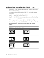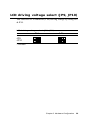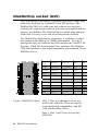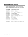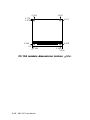
1
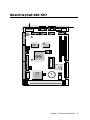
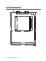
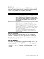
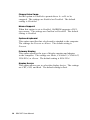
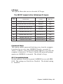
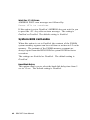
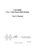
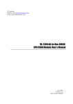
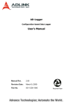
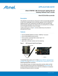
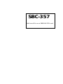
SBC-357
Half-size All-in-one 386SX-40 CPU card
FCC STATEMENT
THIS DEVICE COMPLIES WITH PART 15 FCC RULES.
OPERATION IS SUBJECT TO THE FOLLOWING TWO
CONDITIONS: (1) THIS DEVICE MAY NOT CAUSE HARMFUL INTERFERENCE. (2) THIS DEVICE MUST ACCEPT
ANY INTERFERENCE RECEIVED INCLUDING INTERFERENCE THAT MAY CAUSE UNDESIRED OPERATION.
THIS EQUIPMENT HAS BEEN TESTED AND FOUND TO
COMPLY WITH THE LIMITS FOR A CLASS "A" DIGITAL
DEVICE, PURSUANT TO PART 15 OF THE FCC RULES.
THESE LIMITS ARE DESIGNED TO PROVIDE REASONABLE PROTECTION AGAINTST HARMFUL INTERFERENCE WHEN THE EQUIPMENT IS OPERATED IN A
COMMERCIAL ENVIRONMENT. THIS EQUIPMENT
GENERATES, USES, AND CAN RADIATE RADIO FREQUENCY ENERGY AND , IF NOT INSTATLLED AND USED
IN ACCORDANCE WITH THE INSTRUCTION MANUAL,
MAY CAUSE HARMFUL INTERFERENCE TO RADIO
COMMUNICATIONS. OPERATION OF THIS EQUIPMENT
IN A RESIDENTIAL AREA IS LIKELY TO CAUSE HARMFUL INTERFERENCE IN WHICH CASE THE USER
WILL BE REQUIRED TO CORRECT THE INTERFERENCE AT HIS OWN EXPENSE.
Copyright Notice
This document is copyrighted, 1998, by AAEON Technology Inc.
All rights are reserved. AAEON Technology Inc. reserves the
right to make improvements to the products described in this
manual at any time without notice.
No part of this manual may be reproduced, copied, translated, or
transmitted in any form or by any means without the prior written
permission of AAEON Technology Inc. Information provided in
this manual is intended to be accurate and reliable. However,
AAEON Technology Inc. assumes no responsibility for its use,
nor for any infringements upon the rights of third parties which
may result from its use.
Acknowledgements
ALI is a trademark of Acer Laboratories, Inc.
AMD is a trademark of Advanced Micro Devices, Inc.
AMI is a trademark of American Megatrends, Inc.
AutoCAD and AutoShade are trademarks of Autodesk, Inc.
CHIPS Logotype is a registered trademark; Chips 65550 is a
trademark of Chip and Technologies, Inc.
IBM, PC/AT, PS/2, and VGA are trademarks of International
Business Machines Corporation.
Lotus, 1-2-3, and Symphony are trademarks of Lotus Development Corp.
Microsoft Windows® and MS-DOS are registered trademarks of
Microsoft Corp.
SMC is a trademark of Standard Microsystems Corporation.
TurboDLD Classic is a trademark of Panacea Inc.
UMC is a trademark of United Microelectronics Corporation.
WordPerfect is a trademark of WordPerfect Corporation.
VESA® is a registered trademark of Video Electronics Standards
Association.
All other product names or trademarks are properties of their
respective owners.
Part No. 2047357020 SBC-357 3rd Edition
Printed in Taiwan June, 2000
Packing list
Before you begin installing your card, please make sure that the
following materials have been shipped:
• 1 supporting CD-ROM
• 1 SBC-357 CPU card
• 1 Hard disk drive (IDE) interface cable (40 pin)
• 1 Floppy disk drive interface cable (34 pin)
• 1 6-pin mini-DIN dual outlet adapter for keyboard and PS/2
mouse
• 1 parallel port adapter (26-25 pin) and dual outlet adapter kit
for COM port (10-9 pin) & (14-9 pin) adapter kit
• 2 serial adapter kit (9-10 Pin)
• 1 bag of screws and miscellaneous parts
If any of these items are missing or damaged, contact your distributor or sales representative immediately.
Notice
Dear Customer,
Thank you for purchasing the SBC-357 board. The user manual is
designed to help you to get the most out of the SBC-357, please
read it thoroughly before you install and use the board. This
product that you have purchased comes with a one-year limited
warranty; AAEON will not be responsible for any misuse of the
product. Therefore, we strongly urge that user first read the
manual before using the product.
To receive the lastest version of the user manual, please visit our
Web site at:
Taiwan: www.aaeon.com.tw
U.S.A : www.aaeon.com
Contents
1
General Information............................ 1
Introduction ............................................................................
Features ...................................................................................
Specifications ..........................................................................
Board layout ...........................................................................
Card dimensions .....................................................................
2
2
3
3
5
6
Installation ............................................ 7
Jumpers and connectors ........................................................ 8
Locating jumpers and connectors ......................................... 9
Setting jumpers ..................................................................... 10
Safety precautions ................................................................. 11
Installing DRAM (SIMMs) .................................................. 12
Installing SIMMs .................................................................... 12
Removing SIMMs................................................................... 12
IDE hard drive connector (CN1) ......................................... 13
Floppy drive connector (CN2) ............................................. 15
Connecting the floppy drive .................................................... 15
Parallel (printer) connector (CN3) ...................................... 16
Installing the retaining bracket ................................................. 16
Display connectors (CN10, CN4) ........................................ 17
Reserved IR connector (CN5) .............................................. 19
Power connector (CN6) ........................................................ 19
Serial port connectors (CN7, CN8, CN9, CN11) ................ 20
KB and PS/2 mouse connector (CN12, CN14) ................... 22
Keyboard lock function (CN13) .......................................... 23
IDE LED (JP1) ...................................................................... 24
RS-232/422/485 setting select (JP2) ..................................... 24
Buzzer or external speaker (JP3) ......................................... 25
LCD SHF/ASHF clock select (JP4) ................................. 25
System management Interrupt (JP5) ............................... 26
Hardware Reset (JP6) ........................................................ 26
COM3/COM4 IRQ select (JP7) ...................................... 27
DiskOnChip installation (U15, JP8)................................. 27
LCD driving voltage select (JP9, JP10) ......................... 29
DiskOnChip socket (U15) ................................................. 30
3
AMIBIOS Setup ................................... 31
General information ............................................................ 32
Starting AMIBIOS setup ........................................................ 32
AMIBIOS main menu ............................................................. 32
Using a mouse with AMIBIOS setup ..................................... 33
Using the keyboard with AMIBIOS setup .............................. 33
Standard CMOS setup ....................................................... 34
Advanced CMOS setup ..................................................... 36
Advanced chipset setup ..................................................... 42
Power management setup .................................................. 45
Peripheral Setup .................................................................. 48
Change supervisor password ............................................ 50
Auto configuration with optimal settings ......................... 51
Auto configuration with fail safe settings ........................ 52
Save settings and exit......................................................... 53
Exit without saving ............................................................. 54
4
SVGA Setup......................................... 55
Windows 3.1 ......................................................................... 56
Driver installation - Windows Setup ........................................56
DOS ....................................................................................... 57
SOFTWARE UTILITIES ................................................... 59
The CHIPSCPL utility program .............................................. 59
Installing the utility ................................................................... 59
How to use the utility .............................................................. 59
A
Watchdog Timer Demo Program . 61
Watchdog timer Demo Program ....................................... 62
B
Installing PC/104 Modules ............... 67
Installing PC/104 modules ................................................. 68
CHAPTER
GeneraI
Information
1
This chapter provides background
information for the SBC-357.
Sections include:
· Card specifications
· Board layout
Chapter 1 General Information
1
Introduction
The SBC-357 is an all-in-one single board 386 computer with an
onboard flat panel/CRT SVGA controller. It packs all the
functions of an industrial computer and its display capabilities
onto a single, half-size card. This means the SBC-357 is your
absolute best solution for embedded applications.
The onboard ISA-Bus, flat panel/CRT SVGA controller uses the
CHIPS 65545 chipset with up to 1 MB of video memory (512KB
onboard). It supports various LCD types including TFT, STN,
Normal, and EL.
The SBC-357 supports the optional M-Systems DiskOnChip
2000 which is a new generation of high performance single-chip
Flash Disk. It provides a Flash Disk (as a BIOS expansion) which
doesn't require any bus, slots, or connectors. It is also the optimal
solution for Single Board Computers because of its small size,
easy integration, plug-and-play functionality, and its low power
consumption. The DiskOnChip is available in capacities from
2MB to 72MB and fits in a standard 32-pin DIP socket.
The SBC-357 also features three high speed RS-232 serial ports,
and one RS-232/422/485 serial port with 16C550 UARTs, one
bidirectional SPP/EPP/ECP parallel port, and a floppy drive
controller, all onboard.
If program execution is halted by a program bug or EMI, the
board's watchdog timer can automatically reset the CPU or
generate an interrupt. This ensures reliability in unmanned or
standalone systems.
All configuration is done through software. A single Flash chip
holds the system BIOS, VGA BIOS, and the network boot ROM
image. This minimizes the number of chips and eases configuration. You can change the display BIOS or install a boot ROM
simply by programming the Flash chip.
The SBC-357 supports 5 V EDO or FP DRAM. It also provides
two 72-pin SIMM (Single In-line Memory Module) sockets for
its onboard system DRAM. These sockets give you the flexibility
to configure your system up to 32 MB of DRAM using the most
economical combination of SIMMs.
2 SBC-357 User Manual
Features
• 386SX-40 compatible CPU
• DiskOnChip (SSD) up to 72MB
• Can display both CRT and LCD simultaneously
• Connector for PC/104 module expansion
• Supports 4 serial ports: Three RS-232 ports and one RS-232/422/485
port
Specifications
CPU: Embedded in ALI M6117C Chipset Intel 80386SX-40 compatible
Data bus: 16-bit
BIOS: AMI Flash BIOS (Supports LBA mode HDD)
Chipset: ALI M6117C
Super I/O Chipset: ITE8663BF & ITE8661F
RAM memory: Up to 32MB.Use two 72-pin SIMM socket
Shadow RAM memory: Supports system and video BIOS shadow
memory
IDE hard disk drive interface: Supports up to one IDE (AT bus) hard
disk drives. BIOS auto-detect.
Floppy disk drive interface: Supports up to two floppy disk drive,
5.25”(360KB and 2MB) and /or 3.5”(720KB, 1.44MB and 2.88MB)
Bi-directional parallel port: One Bi-directional printer port (Configurable LPT1, LPT2, LPT3 or disable). Support SPP, ECP and EPP modes.
Serial ports: Three RS-232 serial ports and one RS-232/422/485 serial
port. Uses 16C550 UARTs with 16 byte FIFO. Supports speeds up to
115Kbps.Ports can be individually configured from COM1 to COM4 or
disabled.
Real-time clock/calendar: ALI chipset RTC (internal) and quartz
oscillator power by a lithium battery.
Chapter 1 General Information
3
DMA channel: 7
Interrupt levels: 15
KB/PS2 Mouse connector: 6 pin mini DIN connector supports a
standard PC/AT keyboard and mouse.
Flat panel VGA interface
Chipset: C&T 65545
Display memory: 512KB standard, 1MB option
Display type: Supports CRT and flat panel ( TFT , DSTN, mono and
EL)display, Can display both CRT and flat panel simultaneously.
Resolution: Option up to 1024 x 768 @ 256 colors.(1MB-display
memory). Standard 1024 x 768 @ 16 colors (512KB-display memory)
SSD interface
One 32-pin DIP socket supports M-systems DiskOnChip 2000 series,
memory capacity from 2MB to 72 MB.
Expansion Slot
PC/104 connector: 104-pin connector for a 16 -bit bus expansion.
Mechanical and environmental
Power supply voltage: +5V (4.75V to 5.25V)
Max. power requirements: +5V @ 2A
Operating temperature: 32 to 140 °F (0 to 60°C)
Board Size: 7.3” (L) X 4.8” (W) (185mm x 122mm)
Weight: 0.66 lb. (0.3Kg)
4 SBC-357 User Manual
Board layout SBC-357
ITE
ITE
UM8663F
8661F
F65545 B2
BAT
DiskOnChip
CHIPS
ALI
M6117C
Chapter 1 General Information
5
185.00
73.66
28.80
Card dimensions
19.00
80.645
98.50
121.00
19.60
6 SBC-357 User Manual
CHAPTER
Installation
2
This chapter describes how to set up the
SBC-357 hardware, including instructions on setting jumpers and connecting
peripherals, switches, and indicators. Be
sure to read all safety precautions before
you begin the installation procedure.
Chapter 2 Hardware Configuration
7
Jumpers and connectors
Connectors on the board link it to external devices such as hard
disk drives, a keyboard, or floppy drives. In addition, the board has
a number of jumpers that allows you to configure your system to
suit your application. The table below lists the function of each of
the board jumpers and connectors.
Name
CN1
Function
IDE drive connector
CN2
Flopp drive connector
CN3
Parallel (printer) connector
CN4
LCD connector
CN5
IR connector
CN6
Power connector
CN7
RS-232/422/485 connector (COM2)
CN8
COM1 connector
CN9
COM3 connector
CN10
VGA connector
CN11
COM4 connector
CN12
Internal keyboard connector
CN13
Keyboard lock
CN14
KB/PS2 mouse connector
JP1
IDE LED
JP2
RS-232/422/485 select
JP3
Buzzer or external speaker
JP4
LCD SHF/ASHF clock select
JP5
Green function select (SMI)
JP6
Hardware reset
JP7
COM3/COM4 IRQ select
JP8
DOC address select
JP9
LCD driving voltage select
JP10
LCD voltage select (VGA CHIPSET)
8 SBC-357 User Manual
Locating jumpers and connectors
CN8
CN6
CN10
CN14
CN13
CN12
CN3
CN7
CN9
ITE
ITE
JP2
UM8663F
8661F
CN5
JP9
CN2
CN11
JP8
JP7
F65545 B2
DiskOnChip
CHIPS
CN4
JP4
JP10
BAT
ALI
M6117C
CN1
JP6
JP3
JP1
JP5
Chapter 2 Hardware Configuration
9
Setting jumpers
You configure your card to match the needs of your application by
setting jumpers. A jumper is the simplest kind of electric switch.
It consists of two metal pins and a small metal clip (often
protected by a plastic cover) that slides over the pins to connect
them. To “close” a jumper you connect the pins with the clip. To
“open” a jumper you remove the clip. Sometimes a jumper will
have three pins, labeled 1, 2, and 3. In this case you would
connect either pins 1 and 2 or 2 and 3.
1
Open
Closed
2
3
Closed 2-3
The jumper settings are schematically depicted in this manual as
follows:
1 2 3
Open
Closed
Closed 2-3
A pair of needle-nose pliers may be helpful when working with
jumpers.
If you have any doubts about the best hardware configuration for
your application, contact your local distributor or sales representative before you make any changes.
Generally, you simply need a standard cable to make most
connections.
10 SBC-357 User Manual
Safety precautions
Warning! Always completely disconnect the power cord
from your chassis whenever you are working on
it. Do not make connections while the power is
on because sensitive electronic components can
be damaged by the sudden rush of power. Only
experienced electronics personnel should open
the PC chassis.
Caution!
Always ground yourself to remove any static
charge before touching the CPU card. Modern
electronic devices are very sensitive to static
electric charges. Use a grounding wrist strap at
all times. Place all electronic components on a
static-dissipative surface or in a static-shielded
bag when they are not in the chassis.
Chapter 2 Hardware Configuration
11
Installing DRAM (SIMMs)
The SBC-357 CPU card provides two 72-pin SIMM (Single Inline Memory Module) sockets and supports up to 32MB.
When installing SIMMs, make sure that Bank 1 is filled first.
* The SBC-357 CPU card supports single side F.P or EDO
DRAM module only.
Installing SIMMs
Note: that the modules can only fit into a socket one way.
1. Ensure that all power sources disconnected.
2. Slip the memory module into the socket at a moderate angle.
3. Push the module toward the vertical posts at both ends of the
socket until the module is upright and the retaining clips at
both ends of the module click into place. When positioned
correctly, the pins on top of the vertical posts should correspond to the circular holes on the ends of the module.
4. Repeat steps 2 and 3 for each module you install.
Removing SIMMs
If you need to remove a SIMM, follow the procedures below:
1. Supporting the SIMM with a finger, use a pen or a similarly
shaped object and press one retaining clip straight down.
2. Repeat for the other side. When released, the retaining clips
will push the SIMM up and out of its upright position.
3. Carefully pull the SIMM out of the socket with your fingers.
4. Repeat the above steps for each module you remove.
12 SBC-357 User Manual
IDE hard drive connector (CN1)
You can attach two Enhanced Integrated Device Electronics hard
disk drives to the SBC-357's internal controller. The card comes
with a 40-pin flat piggyback cable. This cable has three identical
40-pin flat-cable connectors.
Connecting the hard drive
Wire number 1 on the cable is red or blue, and the other wires are
gray.
1. Connect one end of the cable to the IDE connector. Make
sure that the red (or blue) wire corresponds to pin 1 on the
connector, which is labeled on the board (on the right side).
2. Plug the other end of the cable to the Enhanced IDE hard
drive, with pin 1 on the cable corresponding to pin 1 on the
hard drive. See your hard drive's documentation for the
location of the connector.
Unlike floppy drives, you can make the connections with any of
the connectors on the cable. If you install two drives, you will
need to set one as the master and one as the slave. You do this
using jumpers on the drives. If you install just one drive, set it as
the master.
Chapter 2 Hardware Configuration
13
Pin assignments
The following table lists the pin numbers and their respective
signals:
IDE Connector (CN1)
Pin
1
Signal
Reset
Pin
2
Signal
GND
3
D7
4
D8
5
D6
6
D9
7
D5
8
D10
9
D4
10
D11
11
D3
12
D12
13
D2
14
D13
15
D1
16
D14
17
D0
18
D15
19
GND
20
N.C.
21
N.C.
22
GND
23
IOW
24
GND
25
IOR
26
GND
27
IORDY
28
BALE
29
N.C.
30
GND
31
IRQ 14
32
-I/O CS16
33
A1
34
N.C.
35
A0
36
A2
37
CS0
38
CS1
39
-ACT
40
GND
14 SBC-357 User Manual
Floppy drive connector (CN2)
You can attach up to two floppy disks to the SBC-357's onboard
controller. You can use any combination of 5 1/4" (360 KB and
1.2 MB) and/or 3 1/2" (720 KB, 1.44 MB, and 2.88 MB) drives.
The SBC-357 CPU card comes with a 34-pin daisy-chain drive
connector cable. On one end of the cable is a 34-pin flat-cable
connector. There are two sets of floppy disk drive connectors,
one in the middle, and one on the other end. Each set consists of
a 34-pin flat-cable connector (usually used for 3.5" drives) and a
printed-circuit board connector (usually used for 5.25" drives).
Connecting the floppy drive
1. Plug the 34-pin flat-cable connector into the CN2 connector.
2. Attach the appropriate connector on the other end of the cable
to the floppy drive(s). You can use only one connector in the
set. The set on the end (after the twist in the cable) connects
to the A: drive. The set in the middle connects to the B: drive.
Pin assignments
The following table lists the pin assignments for the CN2 connector:
Floppy drive connector (CN2)
Pin
1~33 (odd)
Signal
GND
Pin
2
Signal
High density
4, 6
Unused
8
Index
10
Motor enable A
12
Driver select B
14
Driver select A
16
Motor enable B
18
Direction
20
Step pulse
22
Write data
24
Write enable
26
Track 0
28
Write protect
30
Read data
32
Select head
34
Disk change
Chapter 2 Hardware Configuration
15
Parallel (printer) connector (CN3)
Normally, the parallel port is used to connect the card to a printer.
The SBC-357 includes an onboard parallel port, accessed through
the CN3 connector, a 26-pin flat-cable connector. The CPU card
comes with an adapter cable, which lets you use a traditional DB25 connector. The cable has a 26-pin connector on one end and a
DB-25 connector on the other, mounted on a retaining bracket.
Installing the retaining bracket
The retaining bracket installs at an empty slot in your system's
chassis. It provides an external port that gives your parallel
peripheral access to the card's parallel port connector.
1. Find an empty slot in your chassis.
2. Unscrew the plate that covers the end of the slot.
3. Screw in the bracket in place of the plate.
4. Next, attach the flat-cable connector to the CN3 connector.
Wire 1 of the cable is red or blue, and the other wires are gray.
Make sure that Wire 1 connects to Pin 1 of the CN3 connector. Pin 1 is on the right side of the CN3 connector.
Pin assignments
Parallel (printer) Connector (CN3)
Pin
1
Signal
Strobe
Pin
2
Signal
Data 0
3
Data 1
4
Data 2
5
Data 3
6
Data 4
7
Data 5
8
Data 6
9
Data 7
10
-Acknowledge
11
Busy
12
Paper empty
13
+Select
14
-Auto feed
15
-Error
16
-Init printer
17
-Select input
16 SBC-357 User Manual
18~25
GND
Display connectors (CN10, CN4)
The SBC-357 CPU card's SVGA connector (CN10) supports
monochrome displays as well as high resolution color displays.
The card also features an LCD connector (CN4), which allows
you to connect various flat panel displays. The following table
lists their pin assignments:
SVGA connector (CN10)
Pin
1
Signal
Red video
2
Green video
3
Blue video
4
Not used
5
GND
6
Red return (GND)
7
Green return (GND)
8
Blue return (GND)
9
Key (no pin)
10
Sync return (GND)
11
Monitor ID (not used)
12
Monitor ID
13
Horizontal sync
14
Vertical sync
15
Not used
Chapter 2 Hardware Configuration
17
LCD connector (CN4)
Pin
1
Signal
+12 VDC
Pin
2
Signal
+12 VDC
3
GND
4
GND
5
+5 VDC
6
+5 VDC
7
ENA VEE
8
GND
9
P0
10
P1
11
P2
12
P3
13
P4
14
P5
15
P6
16
P7
17
P8
18
P9
19
P10
20
P11
21
P12
22
P13
23
P14
24
P15
25
P16
26
P17
27
P18
28
P19
29
P20
30
P21
31
P22
32
P23
33
GND
34
GND
35
SHIFT CLK
36
FLM
37
M
38
LATCH CL/C
39
GND
40
ENABKL
41
N.C.
42
N.C.
43
N.C.
44
N.C.
18 SBC-357 User Manual
Reserved IR connector (CN5)
IR connector (CN5)
Pin
5
Function
IR_TX
4
GND
3
IR_RX
2
FIR_RX
1
VCC
Power connector (CN6)
In single board computer (non-passive backplane) applications,
you will need to connect the power directly to the SBC-357 board
using CN6. This connector is fully compatible with the standard
PC power supply connectors. See the following table for its pin
assignments:
Power port connector (CN6)
Pin
1
Signal
+5 VDC
2
GND
3
GND
4
+12 VDC
Chapter 2 Hardware Configuration
19
Serial port connectors (CN7, CN8, CN9,
CN11)
The SBC-357 offers three RS-232 serial ports, and one RS-232/422/
485 serial port. You can select or disable the address for each port
with the BIOS Peripheral Setup program.
The card mounting bracket holds COM1(CN8), the DB-9 serial port
connector for the first port. The COM port connectors on the SBC357 board are CN7 (COM2), CN9 (COM3), CN11 (COM4). The
COM2 can be assigned as RS-232 I/F or RS-422/485 I/F. The
following sections describe how to make connections.
1
13
(COM2/CN7)
14
CHIPS
B69000
2
9
5
BAT
Winbond
5582
SIS
6
DiskOnChip
1
(COM1/
CN8, CN9, CN11)
20 SBC-357 User Manual
Pi n
RS-232
RS-422/485
Pi n
RS-232
RS-422/485
1
DCD
DCD
2
D SR
D SR
3
RX
RX
4
RTS
RTS
5
TX
TX
6
CTS
CTS
7
DTR
DTR
8
RI
RI
9
GND
GND
10
NC
NC
11
NC
422TXD+
(485TXD+)
12
NC
422TXD(485TXD-)
13
NC
422TXD+
14
NC
422RXD-
Chapter 2 Hardware Configuration
21
KB and PS/2 mouse connectors (CN12,
CN14)
The SBC-357 board provides two keyboard and one PS/2 mouse
connectors. A 5-pin connector (CN9) supports passive backplane
applications. A second 6-pin mini-DIN keyboard and PS/2 mouse
connector (CN12) on the card mounting bracket supports single
board computer applications.
Keyboard connector (CN12)
Pin
1
Function
K.B. clock
2
K.B. data
3
N.C.
4
GND
5
+5 V DC
KB & PS/2 mouse connector (CN14)
Pin
1
Function
K.B. data
2
PS/2 mouse data
3
GND
4
+5 VDC
5
K.B. clock
6
PS/2 mouse clock
22 SBC-357 User Manual
Keyboard lock function (CN13)
You can use a switch (or a lock) to disable the keyboard. In this
state the PC will not respond to any input. This is useful if you
don’t want anyone to change or stop a running program. Simply
connect the switch between Pins 4 and 5. The pin assignments
appear in the following table:
keylock (CN13)
Pin
1
Function
LED Power (+5 V)
2
N.C
3
Ground
4
Keyboard lock
5
Ground
Chapter 2 Hardware Configuration
23
IDE LED (JP1)
You can connect an LED to indicate that an IDE device is in use.
The pin assignments for this jumper are as follows:
IDE LED (JP1)
Pin
1
Signal
-R/W IDE
2
+Vcc
RS-232/422/485 setting select (JP2)
COM2 can also be assigned as RS-422 or RS-485 I/F. Setting
JP2 to assign CN7 (COM2) as RS-422/RS-485 I/F, or otherwise
assign CN7 (COM2) as RS-232 I/F.
RS-232/422/485 setting select (JP2)
RS-232/422/485 setting select (JP2)
RS-232*
2 4 6
1 3 5
RS-422
2 4 6
1 3 5
RS-485
2 4 6
1 3 5
* default
24 SBC-357 User Manual
Buzzer or external speaker (JP3)
The CPU card has its own buzzer. You can disable the internal
buzzer and connect an external speaker to EXT SPK. Enabling the
external speaker automatically disables the internal buzzer.
Buzzer or External Speaker (JP3)
Buzzer*
External Speaker
1 2 3 4 5
1 2 3 4 5
* default
Buzzer or External speaker (JP3)
Pin
1
Function
Vcc
2
N.C.
3
Buzzer in
4
Speaker output
5
Speaker output
LCD SHF/ASHF clock select (JP4)
You can select the LCD control signals by setting JP1. The
following charts show the available options.
LCD SHF/ASHF Clock select (JP4)
SHF CLK from C&T65545*
1 2 3
ASHF CLK from SHF CLK
1 2 3
* default
Chapter 2 Hardware Configuration
25
System management interrupt (JP5)
The user can connect an external switch or jumper cap enabling
the SMI (System Management Interrupt), makes the system enter
Green function mode.
System management interrupt (JP5)
*
(SMI mode)
* default
Hardware Reset (JP6)
You can connect an external switch to easily reset your computer.
This switch restarts your computer as if you turned off the power
then turned it back on. The following table shows the pin assignments for JP6.
Reset switch (JP6)
Pin
1
Function
Reset
2
Ground
26 SBC-357 User Manual
COM3/COM4 IRQ select (JP7)
COM3/COM4 IRQ select (JP7)
COM3 → IRQ5
COM4 → IRQ10
COM3 → IRQ10
COM4 → IRQ5
COM3 → IRQ11
COM4 → IRQ5
COM3 → IRQ11
COM4 → IRQ10
COM3 → IRQ5
COM4 → IRQ11
COM3 → IRQ10
COM4 → IRQ11
(default)
Chapter 2 Hardware Configuration
27
DiskOnChip Installation (U15, JP8)
Please refer to the DiskOnChip manual for detailed information
about the DiskOnChip.
To install the DiskOnChip on the SBC-357, follow the instructions below.
Step 1:
Install the DiskOnChip in U15.
Step 2:
Set SW1 for the memory address of the DiskOnChip
memory.
SW1 determines the memory adddress of the DiskOnChip
memory. If you have another add-on card in the system that uses
the same memory, neither the SBC-357 nor the add-on card will
function normally. In this case, please change the memory
address.
DiskOnChip address select (JP8)
Disable
DC00
D800
D400
D000*
CC00
* Default
28 SBC-357 User Manual
LCD driving voltage select (JP9, JP10)
You can select LCD connector (CN4) driving voltage by setting JP9
& JP10.
LCD driving voltage select (JP9, JP10)
5V *
3.3V
JP9
JP10
* Default
Chapter 2 Hardware Configuration
29
DiskOnChip socket (U15)
The DiskOnChip 2000 family of products provides a single chip
solid-state flash disk in a standard 32-pin DIP package. The
DiskOnChip 2000 is a solid-state disk with no moving parts,
resulting in a significant reduction in power consumption and an
increase in reliability. The DiskOnChip is a small, plug-and-play
Flash disk. It is easy to use and saves integration overhead.
The DiskOnChip 2000 family of products is available in capacities ranging from 2MB up to 72MB, unformatted. In order to
manage the disk, the DiskOnChip 2000 includes the TrueFFS, MSystems Flash File System proprietary software. The DiskOnChip 2000 package is pin-to-pin compatible with standard 32-pin
EPROM devices.
OE /
Figure 1-MD2200 Pinout
pin
Name
Descr iption
Pin N umber
Dir ection
A0-A12
Addr ess bus
4- 12,23,25-27
Inputs
A13-A16
Addr ess bus
2,3,28,29
Inputs
D0-D7
Data bus
13- 15,17-21
I/O
CE/
C hip Enable
22
Input
OE/
Output Enable
24
Input
WE/
Wr ite Enable
31
Input
NC
Not connected
1.30
VCC
Pow er
32
GND
Ground
16
Note 1: Pins A13 through A16 are not
used by the MD2200. They are kept for
socket backward compatibility with ED
1100 (DiskOnChip 1000)
Note 2: Pins 1 and 30 are not used by
MD2200
30 SBC-357 User Manual
Note
1
2
CHAPTER
AMIBIOS Setup
3
This chapter describes how to set the
BIOS configuration data.
General information
AMIBIOS Setup configures system information that is stored in
CMOS RAM.
Starting AMIBIOS setup
As POST executes, the following appears;
Hit <DEL> if you want to run SETUP
Press <DEL> to run AMIBIOS setup.
AMIBIOS main menu
The AMIBIOS setup screen appears as follows:
AMIBIOS SETUP — BIOS SETUP UTILITIES
(C) 1995 American Megatrends, Inc. All Rights Reserved
Standard CMOS Setup
Advanced CMOS Setup
Advanced Chipset Setup
Power Management Setup
Peripheral Setup
Change User Password
Change Supervisor Password
Change Language Setting
Auto Configuration with Optimal Settings
Auto Configuration with Fail Safe Settings
Save Settings and Exit
Exit Without Saving
Standard CMOS setup for changing time, date, hard disk type, etc.
ESC: Exit
F2/F3: Color F10: Save & Exit
¯- :Sel
32 SBC-357 User Manual
Using a mouse with AMIBIOS setup
AMIBIOS Setup can be accessed via keyboard, mouse. The mouse
click functions are:
• single click to change or select both global and current fields
• double click to perform an operation in the selected field
Using the keyboard with AMIBIOS setup
AMIBIOS Setup has a built-in keyboard driver that uses simple
keystroke combinations:
Keystroke
<tab>
è, ç, é , ê
Function
Move to the next window or field.
Move to the next field to the right,
left, above, or below.
<ENTER>
Select the current field.
+
Increments a value.
Decrements a value.
<ESC>
Close the current operation and return to
the previous level.
<PgUp>
Return to the previous page.
<PgDn>
Advance to the next page.
<Home> Return to the beginning of the text.
<End>
Advance to the end of the text.
<ALT>+H
Access a help window.
<ALT>+<Spacebar> Exit AMIBIOS Setup.
Alphabetic keys
A to Z are used in the Virtual keyboard, and
are not case sensitive.
Numeric keys
0 to 9 are in the Virtual keyboard and
Numeric keypad.
Chapter 3 AMIBIOS Setup 33
Standard CMOS setup
The AMIBIOS Setup options described in this section are
selected by choosing the Standard CMOS Setup from the AMIBIOS Setup main menu selection screen, as shown below.
AMIBIOS SETUP — BIOS SETUP UTILITIES
(C) 1995 American Megatrends, Inc. All Rights Reserved
Standard CMOS Setup
Advanced CMOS Setup
Advanced Chipset Setup
Power Management Setup
Peripheral Setup
Change User Password
Change Supervisor Password
Change Language Setting
Auto Configuration with Optimal Settings
Auto Configuration with Fail Safe Settings
Save Settings and Exit
Exit Without Saving
Standard CMOS setup for changing time, date, hard disk type, etc.
ESC: Exit
F2/F3: Color F10: Save & Exit
¯- :Sel
Press enter, the Standard CMOS Setup screen appears:
AMIBIOS SETUP — STANDARD CMOS SETUP
(C) 1995 American Megatrends, Inc. All Rights Reserved
Date (mm/dd/yyyy): Wed Sep 10, 1998
Time (hh/mm/ss): 12: 19: 46
Floppy Drive A: 1.44 MB 3½
Floppy Drive B: Not Installed
Pri Master
Pri Slave
:
:
Type Size
AUTO
AUTO
Boot Sector Virus Protection
Month:
Day:
Year:
Jan - Dec
01-31
1901 -2099
34 SBC-357 User Manual
Cyln
Head
WPcom
LBA
Sec Mode
On
On
Blk
Mode
On
On
PIO
Mode
AUTO
AUTO
32Bit
Mode
Off
Off
Disabled
Esc: Exit
¯- :Sel
PgUp/PgDn: Modify
F2/F3: Color
Date and Time Configuration
Select the Date and Time icon in the Standard CMOS setup. The
current values for each category are displayed. Enter new values
through the keyboard or hit the "+" or "-" key to change values.
Floppy A, Floppy B
Select the appropriate specifications to configure the type of
floppy drive that is attached to the system: 360 KB 5¼", 1.2 MB
5¼", 720 KB 3½", and/or 1.44 MB 3½". The settings have not
been pre-installed.
Master Disk, Slave Disk
Select the appropriate values to configure the hard disk type you
are using for the master and the slave. Available types are 1~46,
USER, AUTO, Not Installed, and CDROM. The settings have not
been preinstalled.
Boot Sector Virus Protection
Enabling this option allows the system to issue a warning when
any program (or virus) issues a disk format command or attempts
to write to the boot sector of the hard disk drive. Further confirmation is required before accessing this particular section of the
hard disk drive.
Chapter 3 AMIBIOS Setup 35
Advanced CMOS setup
Select the Advanced CMOS Setup icon from the AMIBIOS Setup
main menu to enter Advanced CMOS setup.
The "Advanced CMOS Setup" options described in this section are
the standard options as shown on the following screen.
AMIBIOS SETUP — BIOS SETUP UTILITIES
(C) 1995 American Megatrends, Inc. All Rights Reserved
Standard CMOS Setup
Advanced CMOS Setup
Advanced Chipset Setup
Power Management Setup
Peripheral Setup
Change User Password
Change Supervisor Password
Change Language Setting
Auto Configuration with Optimal Settings
Auto Configuration with Fail Safe Settings
Save Settings and Exit
Exit Without Saving
Standard CMOS setup for changing time, date, hard disk type, etc.
ESC: Exit
F2/F3: Color F10: Save & Exit
¯- :Sel
Press enter, the Advanced CMOS Setup screen appears:
AMIBIOS SETUP — ADVANCED CMOS SETUP
(C) 1995 American Megatrends, Inc. All Rights Reserved
Quick Boot
BootUp Num-Lock
BootUp Sequence
Floppy Drive Swap
Mouse Support
System Keyboard
Primary Display
Display Device
LCD Type
Password Check
OS/2 Compatible Mode
Wait For 'F1' if error
System BIOS Cacheable
Hard disk Delay
C000, 32k Shadow
C800, 32k Shadow
D000, 32k Shadow
D800, 32k Shadow
E000, 32k Shadow
E800, 32k Shadow
36 SBC-357 User Manual
Enabled
On
C:,A:
Disabled
Enabled
Present
VGA/EGA
Both
640 18BTFT 1
Setup
Disabled
Enabled
Enabled
Disabled
Enabled
Disabled
Disabled
Disabled
Disabled
Disabled
Available Options:
Disabled
Enabled
ESC: Exit ¯- :Sel
PgUp/PgDn: Modify
F2/F3: Color
Quick Boot
Set this option to Enabled to instruct AMIBIOS to boot quickly
when the computer is powered on. This option replaces the old
"Above 1 MB Memory Test" Advanced Setup option.
Setting
Description
Disabled AMIBIOS tests all system memory. AMIBIOS waits up to 40
seconds for a READY signal from the IDE hard disk
drive. AMIBIOS waits for .5 seconds after sending a
RESET signal to the IDE drive to allow the IDE drive
time to get ready again. AMIBIOS checks for a <Del>
key press and runs AMIBIOS Setup if the key has
been pressed.
Enabled
AMIBIOS does not test system memory above 1 MB.
AMIBIOS does not wait up to 40 seconds for a
READY signal from the IDE hard disk drive. If a
READY signal is not received immediately from the
IDE drive, AMIBIOS does not configure that drive.
AMIBIOS does not wait for .5 seconds after sending a
RESET signal to the IDE drive to allow the IDE drive
time to get ready again.
You cannot run AMIBIOS Setup at system boot,
because there is no delay for the Hit <Del> to run
Setup message.
Boot Up Num Lock
Set this option to Off to turn the Num Lock key off when the
computer is booted so you can use the arrow keys on both the
numeric keypad and the keyboard. The settings are On or Off.
The default setting is On.
Boot Up Sequence
This option sets the sequence of boot drives (floppy drive A:, or
hard disk drive C:) that the AMIBIOS attempts to boot from after
AMIBIOS POST completes. The settings are C:,A:,CDROM,
CDROM,A:,C:, or A:,C:,CDROM. The default setting is A:, C:,
CDROM.
Chapter 3 AMIBIOS Setup 37
Floppy Drive Swap
Set this option to Enabled to permit drives A: or B: to be
swapped. The settings are Enabled or Disabled. The default
setting is Disabled.
Mouse Support
When this option is set to Enabled, AMIBIOS supports a PS/2type mouse. The settings are Enabled or Disabled. The default
setting is Enabled.
System Keyboard
This option specifies that a keyboard is attached to the computer.
The settings are Present or Absent. The default setting is
Present.
Primary Display
This option specifies the type of display monitor and adapter
in the computer. The settings are Mono, CGA40x25, CGA80x25,
VGA/EGA, or Absent. The default setting is EGA/VGA.
Display Device
This option allows user to select the display device. The settings
are CRT, LCD, and Both. The default setting is Both.
38 SBC-357 User Manual
LCD type
This option allows the user to select the LCD type.
The SBC357 supports the following LCD types:
Brand
name
Model name
Format
SBC-357
Sharp
640x480 16bit Color DSTN TFT
LM64C08P
Y ES
Sharp
640x480 8bit Dual-Scan Mono STN
LM64P11
Y ES
Sharp
640x480 8bit Dual-Scan EL
LJ64H052
Y ES
Sharp
640x480 18bit Color TFT 1
LQ10D41
Y ES
NEC
640x480 12bit Color TFT
NL6448AC30-10
Y ES
NEC
640x480 18bit Color TFT 2
NL6448AC33-18
Y ES
NEC
800x600 18bit Color TFT
NL8060AC26-11
Y ES
NEC
640x480 4 bit PLASMA
PG6404SORM16-3
Y ES
Password Check
This option enables password checking every time the computer
is powered on or every time AMIBIOS Setup is executed. If
Always is chosen, a user password prompt appears every time the
computer is turned on. If Setup is chosen, the password prompt
appears as AMIBIOS is executed. The default is Setup.
OS/2 Compatible Mode
Set this option to Enabled to permit AMIBIOS to run with IBM
OS/2. The settings are Enabled or Disabled. The default setting
is Disabled.
Chapter 3 AMIBIOS Setup 39
Wait for F1 if Error:
AMIBIOS POST error messages are followed by:
Press <F1> to continue
If this option is set to Disabled, AMIBIOS does not wait for you
to press the <F1> key after an error message. The setting is
Enabled or Disabled. The default setting is Enabled.
System BIOS cacheable
When this option is set to Enabled, the contents of the F0000h
system memory segment can be read from or written to L2 cache
memory. The contents of the F0000h memory segment are
always copied from the BIOS ROM to system RAM for faster
execution.
The settings are Enabled or Disabled. The default setting is
Disabled.
Hard Disk Delay
This option allows you to select the hard disk delay time from 5
sec to 15 sec. The default setting is Disabled.
40 SBC-357 User Manual
ROM Location Setting
C000, 32K Shadow
D000, 32K Shadow
E000, 32K Shadow
C800, 32K Shadow
D800, 32K Shadow
E800, 32K Shadow
These options control the location of the contents of the 16KB of
ROM beginning at the specified memory location. If no adapter
ROM is using the named ROM area, this area is made available to
the local bus. The settings are:
Setting
Shadow
Description
Enabled
If an adapter ROM will be using the named ROM
area, ROM area are written to the same address in
system memory (RAM) for faster execution. Also,
the contents of the RAM area can be read from and
written to cache memory.
The video ROM is not copied to RAM. The contents of
the video ROM cannot be read from or written to cache
memory.
Disabled
The contents of C0000h - C3FFFh are written to the
same address in system memory (RAM) for faster
execution.
Chapter 3 AMIBIOS Setup 41
Advanced chipset setup
Select the Advanced Chipset Setup from the AMIBIOS Setup
main menu to enter the Chipset Setup. The following configurations are based on the manufacturer's default settings.
This section allows you to configure the system based on the
specific features of the installed chipset. This chipset manages
bus speeds and access to system memory resources, such as
DRAM and the external cache. It also coordinates communications between the conventional ISA bus and the PCI bus. It must
be stated that these items should never need to be altered. The
default settings have been chosen, because they provide the best
operating conditions for your system.
AMIBIOS SETUP — BIOS SETUP UTILITIES
(C) 1995 American Megatrends, Inc. All Rights Reserved
Standard CMOS Setup
Advanced CMOS Setup
Advanced Chipset Setup
Power Management Setup
Peripheral Setup
Change User Password
Change Supervisor Password
Change Language Setting
Auto Configuration with Optimal Settings
Auto Configuration with Fail Safe Settings
Save Settings and Exit
Exit Without Saving
Standard CMOS setup for changing time, date, hard disk type, etc.
ESC: Exit
F2/F3: Color F10: Save & Exit
¯- :Sel
AMIBIOS SETUP — ADVANCED CHIPSET SETUP
(C) 1995 American Megatrends, Inc. All Rights Reserved
AT Bus Clock
DRAM Refresh Type
DRAM Self-Refresh
Slow Refresh
RAS Precharge time
RAS Active Time Insert wait
CAS Precharge Time Insert Wait
Memory Write Insert Wait
Memory Miss Read Insert Wait
ISA I/O High Speed
ISA Memory High Speed
ISA Write cycle end Insert Wait
Memory Hole at 15-16M
I/O Recovery
I/O Recovery Period
16Bit ISA Insert Wait
42 SBC-357 User Manual
:14. 318/2
:RAS only
:Disable
:15 us
:2.5T
:Enabled
:Enabled
:Disabled
:Disabled
:Disabled
:Disabled
:Enabled
:Disabled
:Enabled
:0.50 us
:Enabled
Available Options:
14.318/2
PCLK 2/3
PCLK 2/4
PCLK 2/6
PCLK 2/8
PCLK 2/10
PCLK 2/12
ESC: Exit ¯- :Sel
PgUp/PgDn: Modify
F2/F3: Color
Chipset setup options
Function
At Bus Clock
DRAM Refresh Type
DRAM Self-Refresh
Slow Refresh
RAS Precharge Time
RAS Active Time Insert Wait
CAS Precharge Time Insert Wait
Memory Write Insert Wait
Memory Miss Read Insert Wait
ISA I/O High Speed
ISA memory High Speed
ISA Write Cycle and Insert Wait
option
14.318/2
PCLK 2/3
PCLK 2/4
PCLK 2/5
PCLK 2/6
PCLK 2/8
PCLK 2/10
PCLK 2/12
CAS/RAS
RAS only
Disabled
Enabled
15 µs
60 µs
120 µs
2.5T
1.5T
3.5T
Disabled
Enabled
Disabled
Enabled
Disabled
Enabled
Disabled
Enabled
Disabled
Enabled
Disabled
Enabled
Disabled
Enabled
Chapter 3 AMIBIOS Setup 43
Memory Hole At 15-16M
I/O Recovery
I/O Recovery Peried
16 Bit ISA Insert Wait
44 SBC-357 User Manual
Disabled
Enabled
Enabled
Disabled
0 µs
0.25 µs
0.50 µs
0.75 µs
1.00 µs
1.25 µs
1.50 µs
1.75 µs
2.00 µs
2.25 µs
2.50 µs
2.75 µs
3.00 µs
3.25 µs
3.50 µs
Enabled
Disabled
Power management setup
The Power management setup offers options to help reduce
power consumption. To see the options in this group, choose the
Power management setup icon from the AMIBIOS setup main
menu.
AMIBIOS SETUP — BIOS SETUP UTILITIES
(C) 1995 American Megatrends, Inc. All Rights Reserved
Standard CMOS Setup
Advanced CMOS Setup
Advanced Chipset Setup
Power Management Setup
Peripheral Setup
Change User Password
Change Supervisor Password
Change Language Setting
Auto Configuration with Optimal Settings
Auto Configuration with Fail Safe Settings
Save Settings and Exit
Exit Without Saving
Standard CMOS setup for changing time, date, hard disk type, etc.
ESC: Exit
F2/F3: Color F10: Save & Exit
¯- :Sel
AMIBIOS SETUP — ADVANCED CHIPSET SETUP
(C) 1995 American Megatrends, Inc. All Rights Reserved
Power Management Mode
Clock down in Doze
Doze Mode Timeout
Standby Mode Timeout
Suspend Mode Timeout
Power Down HDD in
Power Down VGA in
VGA Power Down Mode
Monitor DRQs
DRQ 0 Event
DRQ 1 Event
DRQ 2 Event
DRQ 3 Event
DRQ 5 Event
DRQ 6 Event
DRQ 7 Event
Monitor FDD
Monitor COM
Monitor LPT
Monitor IRQs
:Disabled
:Disabled
:Disabled
:Disabled
:Disabled
:Disabled
:Disabled
:Normal
:Disabled
:Disabled
:Disabled
:Disabled
:Disabled
:Disabled
:Disabled
:Disabled
:Disabled
:Disabled
:Disabled
:Disabled
Available Options:
Disabled
SMI
:Enabled
¯- :Sel
ESC: Exit
PgUp/PgDn: Modify
F2/F3: Color
Chapter 3 AMIBIOS Setup 45
Power management mode
Power management lets you set up your computer to save
electricity when it is not actively in use by putting the system into
progressively greater power saving modes. In the power management scheme there are four system states which proceed in the
following sequence:
Disabled à
SMI
There are two selections for Power Management (Mode):
Disabled
Turns off PM
SMI
Maximized power saving by activating
maximum power saving settings after one
minute of system inactivity.
With the exception of Disabled, SMI selections have "fixedmode" settings. Therefore, when PM is set to Disabled, some
items which are predefined will become unmodifiable.
Power down HDD in
When enabled and after the selected time of system inactivity, the
hard disk drive will be powered down while all other devices will
remain active.
Doze mode timeout
This sets the period of system inactivity after which the system
goes into Doze mode, the most limited power saving state. The
settings range from 10 seconds to 2 hours and can be set manually when power management is in SMI. The default setting is
Disabled. When the system goes into power saving mode, power
management will skip to the next mode in the sequence if this is
disabled.
46 SBC-357 User Manual
Standby mode timeout
This sets the period of system inactivity after which the system
goes into Standby mode, the intermediate power saving state.
The settings range from 10 seconds to 2 hours and can be set
manually when power management is in SMI. The default setting
is Disabled. When the system goes into power saving mode,
power management will skip to the next mode in the sequence if
this is disabled.
Suspend mode timeout
This sets the period of system inactivity after which the system
goes into Suspend mode, the maximum power saving state. The
settings range from 10 seconds to 2 hours and can be set manually when power management is in SMI. The default setting is
Disabled. When the system goes into power saving mode, power
management will skip to the next mode in the sequence if this is
disabled.
Chapter 3 AMIBIOS Setup 47
Peripheral Setup
Peripheral Setup options are displayed by choosing the Peripheral
Setup icon from the AMIBIOS Setup main menu. All Peripheral
Setup options are described in this section:
AMIBIOS SETUP — BIOS SETUP UTILITIES
(C) 1995 American Megatrends, Inc. All Rights Reserved
Standard CMOS Setup
Advanced CMOS Setup
Advanced Chipset Setup
Power Management Setup
Peripheral Setup
Change User Password
Change Supervisor Password
Change Language Setting
Auto Configuration with Optimal Settings
Auto Configuration with Fail Safe Settings
Save Settings and Exit
Exit Without Saving
Standard CMOS setup for changing time, date, hard disk type, etc.
ESC: Exit
F2/F3: Color F10: Save & Exit
¯- :Sel
AMIBIOS SETUP — PERIPHERAL SETUP
(C) 1995 American Megatrends, Inc. All Rights Reserved
Onboard IDE
Onboard FDC
Onboard Parallel Port
Parallel Port Mode
ECP DMA
Parallel Port IRQ
Onboard Serial Port 1
Onboard Serial Port 1 RQ
Onboard Serial Port 2
Onboard Serial Port 2 IRQ
Onboard Serial Port 3
Onboard Serial Port 3 IRQ
Onboard Serial Port 4
Onboard Serial Port 4 IRQ
:Enabled
:Enabled
:378
:SPP
:DMA3
:IRQ7
:3F8
:4
:2F8
:3
:3E8h
:IRQ-A
:2E8h
:IRQ_B
Available Options:
Disabled
Enabled
ESC: Exit ¯- :Sel
PgUp/PgDn: Modify
F2/F3: Color
Onboard IDE
This option specifies the onboard IDE controller channels that
will be used. The settings are Disabled or Enabled.
Onboard FDC
This option enables the floppy drive controller on the motherboard. The settings are Enabled, or Disabled.
48 SBC-357 User Manual
Onboard Parallel Port
This option enables the parallel port on the motherboard and
specifies the parallel port base I/O port address. The settings are
Disabled, 278, 378, and 3BC. The default setting is Enabled.
Parallel Port Mode
This option specifies the parallel port mode. ECP and EPP are
both bidirectional data transfer sechemes that adhere to the IEEE
P1284 specification. The settings are:
Setting
Description
Normal
The normal parallel port mode is used. This is the
default setting.
EPP
The parallel port can be used with devices that adhere
to the Enhanced Parallel Port (EPP) specification.
EPP uses the existing parallel port signals to provide
asymmetric bidirectional data transfer driven by the
host device.
The parallel port can be used with devices that adhere
to the Extended Capabilities Port (ECP) specification.
ECP uses the DMA protocol to achieve transfer rates
of approximately 2.5 Mbs. ECP provides symmetric
bidirectional communications.
ECP
ECP DMA
This option is setting for the Parallel Port Mode.
The settings are DMA, CH (channel) 0, DMA CH 1, DMA CH2,
or DMA CH3.
Parallel Port IRQ
IRQ7 is used for the Parallel Port (LPT 1). The IRQ can be
changed to IRQ5.
Onboard Serial Port 1/2/3/4
This option enables serial port 1 on the motherboard and
specifies the base I/O port address for serial port 1~4.
The settings are Disabled, 3F8h, 3E8h, 2E8h, and 2F8h.
Chapter 3 AMIBIOS Setup 49
Change supervisor password
1) Select this option from the main menu
2) Enter the Password and Press <Enter>
3) Retype the Password and Press <Enter>
If you forget the password, please contact your distributor for
another password which you can use to enter the AMIBIOS setup
and change your own password.
AMIBIOS SETUP — BIOS SETUP UTILITIES
(C) 1995 American Megatrends, Inc. All Rights Reserved
Standard CMOS Setup
Advanced CMOS Setup
Advanced Chipset Setup
Power Management Setup
Peripheral Setup
Change User Password
Change Supervisor Password
Change Language Setting
Auto Configuration with Optimal Settings
Auto Configuration with Fail Safe Settings
Save Settings and Exit
Exit Without Saving
Standard CMOS setup for changing time, date, hard disk type, etc.
ESC: Exit
F2/F3: Color F10: Save & Exit
¯- :Sel
50 SBC-357 User Manual
Auto configuration with optimal
settings
You can load the optimal default settings for the AMIBOIS setup
options by selecting it from the main menu. The optimal default
settings are best case values that should optimize system performance. If CMOS RAM is corrupted, the optimal settings are
loaded automatically.
AMIBIOS SETUP — BIOS SETUP UTILITIES
(C) 1995 American Megatrends, Inc. All Rights Reserved
Standard CMOS Setup
Advanced CMOS Setup
Advanced Chipset Setup
Power Management Setup
Peripheral Setup
Change User Password
Change Supervisor Password
Change Language Setting
Auto Configuration with Optimal Settings
Auto Configuration with Fail Safe Settings
Save Settings and Exit
Exit Without Saving
Standard CMOS setup for changing time, date, hard disk type, etc.
ESC: Exit
F2/F3: Color F10: Save & Exit
¯- :Sel
Chapter 3 AMIBIOS Setup 51
Auto configuration with fail safe
settings
You can load the Fail Safe settings for the AMIBOIS setup
options by selecting it from the main menu. The Fail Safe
settings provide the most stable settings, though they may not
provide optimal performance. Use this option as a diagnostic aid
if the system is behaving erratically.
AMIBIOS SETUP — BIOS SETUP UTILITIES
(C) 1995 American Megatrends, Inc. All Rights Reserved
Standard CMOS Setup
Advanced CMOS Setup
Advanced Chipset Setup
Power Management Setup
Peripheral Setup
Change User Password
Change Supervisor Password
Change Language Setting
Auto Configuration with Optimal Settings
Auto Configuration with Fail Safe Settings
Save Settings and Exit
Exit Without Saving
Standard CMOS setup for changing time, date, hard disk type, etc.
ESC: Exit
F2/F3: Color F10: Save & Exit
¯- :Sel
52 SBC-357 User Manual
Save settings and exit
If you select this option and press <Enter>, the values entered in
the setup utilities will be recorded in the chipset's CMOS
memory. The microprocessor will check this every time you turn
your system on and compare this to what it finds as it checks the
system. This record is required for the system to operate.
AMIBIOS SETUP — BIOS SETUP UTILITIES
(C) 1995 American Megatrends, Inc. All Rights Reserved
Standard CMOS Setup
Advanced CMOS Setup
Advanced Chipset Setup
Power Management Setup
Peripheral Setup
Change User Password
Change Supervisor Password
Change Language Setting
Auto Configuration with Optimal Settings
Auto Configuration with Fail Safe Settings
Save Settings and Exit
Exit Without Saving
Standard CMOS setup for changing time, date, hard disk type, etc.
ESC: Exit
F2/F3: Color F10: Save & Exit
¯- :Sel
Chapter 3 AMIBIOS Setup 53
Exit without saving
Selecting this option and pressing <Enter> lets you exit the Setup
program, without recording any new values or changing old ones.
AMIBIOS SETUP — BIOS SETUP UTILITIES
(C) 1995 American Megatrends, Inc. All Rights Reserved
Standard CMOS Setup
Advanced CMOS Setup
Advanced Chipset Setup
Power Management Setup
Peripheral Setup
Change User Password
Change Supervisor Password
Change Language Setting
Auto Configuration with Optimal Settings
Auto Configuration with Fail Safe Settings
Save Settings and Exit
Exit Without Saving
Standard CMOS setup for changing time, date, hard disk type, etc.
ESC: Exit
F2/F3: Color F10: Save & Exit
¯- :Sel
54 SBC-357 User Manual
CHAPTER
SVGA Setup
4
The SBC-357 features an onboard flat
panel/SVGA interface. This chapter
provides instructions for installing
and operating the software drivers on
the included display driver diskette.
Windows 3.1
These drivers are designed to work with Microsoft Windows
Version 3.1. You may install these drivers either through Windows
or in DOS.
Driver installation - Windows Setup
1. Install Windows as you normally would for a VGA display. Run
Windows to make sure that it is working correctly.
2. Place the Supporting CD-ROM into your CD-ROM drive. In
the Windows Program Manager, choose File from the Options
Menu. Then from the pull-down menu, choose Run. At the
Command Line prompt, type
cd-rom drive: \CD ROM\model name\sbc-357\vga driver
\Oemsetup.inf.
"cd-rom": the drive letter of your CD-ROM drive
"model name": the model number of your product
Press the <ENTER> key or click OK to begin the installation.
At this point the setup program locates the directory where
Windows is installed. For proper operation, the drivers must
be installed in the Windows subdirectory.
3. Press <ENTER> to complete the installation. Once completed,
the Display Driver Control Panel appears on the screen. You
can find the ChipCPL under the Control Panel. The icon allows
you to select and load the installed drivers.
Changing Display Drivers from Windows
To change display drivers from Windows, select the Windows
Setup icon from the Main window. You will be shown the current
setup configuration. Select Change System Settings from the
Option menu. Click on the arrow at the end of the Display line. You
will be shown a list of display drivers. Click on the driver you want
to select. Then click on the OK button. Follow the directions to
complete the setup.
56
SBC-357 User Manual
Changing Color Schemes
After you change display drivers, you may notice that the color
scheme used by Windows looks strange. This is because different
drivers have different default colors. You can correct this by
choosing the same color scheme or a new color scheme. First select
the Control Panel from the Main window. Select the Color icon.
You will be shown the current color scheme. Choose a new color
scheme and click the OK button.
DOS
Driver installation - DOS Setup
1. Install Windows as you normally would for a VGA display. Run
Windows to make sure that it is working correctly. Then exit
from Windows.
2. Place the Supporting CD-ROM into yur CD-ROM drive. Type
cd-rom drive:
<ENTER> to make this the default drive.
3. Type "\CD ROM\model name\sbc-357\357\vga driver\setup"
<ENTER> to run the driver SETUP program. Press any key to
get to the applications list.
"cd-rom": the drive letter of your CD-ROM drive
"model name": the model number of your product
4. Using the arrow keys, select Windows Version 3.1 and press the
<ENTER> key. Press the <ENTER> key to select All Resolutions, then press <END> to begin the installation.
5. At this point you will be asked for the path to your Windows
System directory (default C:\WINDOWS). When the installation is complete, press any key to continue. Press <ESC>
followed by Y to exit to DOS.
6. Change to the directory where you installed Windows (usually
C:\WINDOWS).
Chapter 4 SVGA Setup
57
7. Type SETUP <ENTER> to run the Windows Setup program. It
will show the current Windows configuration. Use the up arrow
key to move to the Display line and press <ENTER>.
8. A list of display drivers will be shown. Use the arrow keys to
select one of the drivers starting with an asterisk (*) and press
<ENTER>.
9. Follow the directions on the screen to complete the setup. In
most cases, you may press <ENTER> to accept the suggested
option.
Start Windows with the new display driver.
Changing Display Drivers from DOS
To change display drivers from DOS, change to the Windows
directory and run Setup, repeating steps 4 and 5 from the previous
page. Besides the special display drivers marked by an asterisk (*),
you should be able to use the following standard drivers:
VGA
Super VGA
640 x 480, 16 colors
800 x 600, 16 colors
Panning Drivers
Special panning drivers are provided to allow high-resolution
modes to be displayed on a flat panel or CRT. These drivers will
show a section of a larger screen, and will automatically pan or
scroll the screen horizontally and vertically when the mouse
reaches the edge of the display.
58
SBC-357 User Manual
SOFTWARE UTILITIES
This chapter describes the operation and installation of the display
drivers supplied on the Supporting CD-ROM that are shipped with
your product.
• CHIPSCPL
The CHIPSCPL utility program
This utility program is designed to work with MicrosoftÒ WindowsÔ Version 3.1.
Installing the utility
CHIPSCPL.CPL is a WindowsÔ based utility to select resolutions
and color depth. It is a Control Panel Applet with its own icon that is
automatically installed when installing the CHIPS WindowsÔ 3.1
linear drivers. The Control Panel icon is in the Main WindowsÔ
group. To invoke the control panel applet, simply-double click on the
icon. The driver resolution and color depth take effect only after
Windows is rebooted with the new driver.
How to use the utility
SCREEN SIZE <ALT S> allows you to select from the following
resolutions:
• 640 x 480
• 800 x 600
• 1024 x 786
• 1280 x 1024
Chapter 4 SVGA Setup
59
If you select the resoution first, the allowable color depth choices
will automatically be shown.
COLOR <ALT O> allows you to select the number of colors from
the following:
•
•
•
•
•
16 (4 bits per pixel)
256 (8 bpp)
32K (15 bpp)
64K (16 bpp)
16M (24 bpp)
If you select color depth first, the allowable resolution choices will
automatically be shown.
DPI<ALT P> allows you to select a large or small font.
DISPLAY<ALT D> allows you to select the display type from the
following:
• CRT only
• LCD (Flat Panel) only
• Both CRT and LCD (flat Panel)
60
SBC-357 User Manual
APPENDIX
A
Watchdog Timer
Sample Programs
The following sample programs
illustrates the programming steps
required to enable, set, and disable the
watchdog timer.
Watchdog timer
The watchdog timer uses 32.768 MHz frequency source to
counter a 24-bit Counter, so the timer range is from 30.5u sec to
512 sec with resolution 30.5u sec. When timer times out, a
system reset, NMI or IRQ may happen to be decided by user’s
programming.
Configuration register
The watchdog timer of SBC-357 is located on the chipset - ALI
M6117C. If you want to use it, you have to know how to read/
write the configuration register of M6117C. Following is the
basic procedure.
1. Open the chip.
2. Write/Read data to/from register.
3. Close the chip.
To Open/Close the chip is to write a specific value to register
13h.
Index 13h:
c5h: open the chip
ooh: close the chip
Here we give you an example of writing data to register.
mov
al, 13h
Out
22h, al
jmp
$+2
;;delay
jmp
$+2
;;delay
mov
al, oc5h
out
23h, al
* note: 22h is the index I/O port, 23h is the data I/O port.
How to set the watchdog timer
62 SBC-357 User Manual
1. Set index 37h bit 6 = o to disable the timer.
2. Write the desired counter value to 3Bh, 3Ah, 39h.
3. Set index 37h bit 6 = 1 to enable the timer.
4. When counter reaches the setting value, the timer will
generate signal setting by index 38h bit [7:4]
Index 3Bh, 3Ah, 39H
counter
3Bh
3Ah
39h
D7......D0
D7......D0
D7......D0
MSB
LSB
Index 38h
D[7:4]
timeeout signal
0000
Reservd
0001
IRQ3
0010
IRQ4
0011
IRQ5
0100
IRQ6
0101
IRQ7
0110
IRQ9
0111
IRQ10
1000
IRQ11
1001
IRQ12
1010
IRQ14
1011
IRQ15
1100
NMI
1101
System reset
1110
Reserved
1111
Reserved
Appendix A Watchdog Timer Demo Program
63
Example
Following is an example of programming 1 sec period for
watchdog timer in assembly language. When timer times out, is
will generate system reset.
IO_Delay MACRO
jcxz
jcxz
ENDM
$+2
$+2
Open_Chip MACRO
push
ax
mov
al,013h
out
22h,al
IO_Delay
mov
al,0c5h
out
23h,al
IO_Delay
pop
ax
ENDM
Close_Chip MACRO
push
ax
mov
al,13h
out
22h,al
IO_Dealy
mov
al,0
out
23h,al
IO_Delay
pop
ax
ENDM
Write_To_Chip PROC
;;Input: ah - Data
;;
al - Index#
cli
Open_Chip
out
22h,al
IO_Delay
xchg
ah,al
out
23H,AL
IO_Delay
Close_Chip
sti
ret
ENDP
64 SBC-357 User Manual
Read_From_Chip
PROC
;;Input: al - Index#
;;Output al - Data
cli
Open_Chip
out
22h,al
IO_Delay
in
al,23h
IO_Delay
Close_chip
sti
ret
ENDP
Watchdog_Timer_Program:
Open_Chip
mov
al,37h
call
Read_From_Chip
mov
bl,al
;;save register data
and
al,10111111b
;;set bit6=0 to disable
timer
mov
ah,al
mov
al,37h
call
Write_To_Chip
mov
ah,33
;;1 msec=33x30.5u sec
mov
al,39h
call
Write_To_Chip
mov
ax,003ah
call
Write_To_Chip
mov
ax,003bh
call
Write_To_Chip
mov
al,bl
mov
al,38h
call
Read_From_Chip
and
al,00001111B
or
al,11010000b
;;set time-out event aas
system reset
mov
ah,al
mov
al,38h
call
mov
or
Write_to_Chip
al,bl
al,01000000b
mov
mov
call
ah,al
al,37h
Write_To_Chip
;;set bit6 = 1 to enable
timer
Appendix A Watchdog Timer Demo Program
65
66 SBC-357 User Manual
APPENDIX
B
Installing PC/104
Modules
This appendix gives instructions for
installing PC/104 Modules.
Appendix B Installing PC/104 Modules
B-67
Installing PC/104 modules
The SBC-357's PC/104 connectors give you the flexibility to
attach PC/104 expansion modules. These modules perform the
functions of traditional plug-in expansion cards, but save space
and valuable slots. Modules include:
•
•
•
•
•
•
•
•
•
•
•
•
•
•
•
•
PCM-3110B
PCM-3115B
PCM-3200
PCM-3420
PCM-3521
PCM-3522
PCM-3600
PCM-3610
PCM-3640
PCM-P50
PCM-3660
PCM-3718
PCM-3724
PCM-3910
PCM-3810
PCM-3820
B-68 SBC-357 User Manual
PCMCIA Module (one-slot)
PCMCIA Module (two-slot)
PC/104 Sound Module
PC/104 Fast SCSI Module
Advanced Flat-Panel/CRT VGA Module
LCD Panel Adapter
PC/104 Fax/Modem Module
Isolated RS-232 and RS-422/485 Module
PC/104 4-port RS-232 Module
PC/104 vehicle Power Supply
Ethernet Module
30 KHz A/D Module
48-channel DIO Module
Breadboard Module
Solid State Disk Module
High Density Flash Solid State Disk Module
Installing these modules on the SBC-357 is a quick and simple
operation. The following steps show how to mount the PC/104
modules:
Step1
Remove the SBC-357 from your system, paying
particular attention to the safety instructions already
mentioned above.
Step2
Make any jumper or link changes required to the CPU
card now. Once the PC/104 module is mounted, you
may have difficulty in accessing these.
Step3
Mount the PC/104 module onto the CPU card. Do this
by pressing the module firmly but carefully onto the
mounting connectors.
Step4
Secure the PC/104 module onto the CPU card using
the four mounting spacers and srews.
PC/104
Mounting Support
Female
Main board
Male
PC/104 Module
PC/104 Module Mounting Diagram
Appendix B Installing PC/104 Modules
B-69
0.300
3.775
3.575
3.250
3.575
0.200
0.200
0
0
0.200
3.350
3.550
PC/104 module dimensions (inches ±5%)
B-70 SBC-357 User Manual