1
Sontay SonNet Radio Sensor System User Manual Version 4.2 August 2015
®
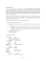
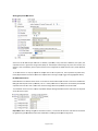
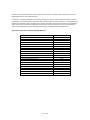
Page 1 of 83 Audience This manual is intended for specifiers, users and installers of the Sontay® SonNet radio sensor system. Content This manual provides a complete reference for the Sontay® SonNet radio sensor system. Related Documents The Sontay® SonNet radio sensor system Site Survey Kit Quick Start Guide The Sontay® SonNet radio sensor system Site Survey Kit Manual The Sontay® SonNet radio sensor system Quick Start Guide The Sontay® SonNet radio sensor system product datasheets Page 2 of 83 Table of Contents: Overview .................................................................................................... 5 Environmental .............................................................................................. 5 Battery Fitting and Replacement........................................................................... 5 Disposal of Batteries........................................................................................ 5 Devices Types ............................................................................................... 6 Battery Powered Nodes .......................................................................... 6 24V Powered Routers............................................................................. 8 230Vac Powered Routers ........................................................................ 10 The System Receiver ............................................................................. 11 The RF‐IOM ...................................................................................... 12 The Radio Network ........................................................................................ 14 Network Planning Considerations .............................................................. 15 The Radio System .......................................................................................... 17 Security .................................................................................................... 17 How the Self‐Healing Tree Network is Formed ........................................................... 17 Propagation Of Radio Signals in Buildings ................................................................ 18 Extension Aerials .......................................................................................... 19 FAQs ........................................................................................................ 20 Configuration & Monitoring Software .................................................................... 22 Important – Disabling Driver Signing Verification .............................................. 22 Windows 7 64‐bit ................................................................................ 22 Windows 8 ....................................................................................... 23 Windows 8.1 ..................................................................................... 23 Windows 10 ...................................................................................... 23 Installing CMS .................................................................................... 24 Starting CMS ..................................................................................... 27 Importing a Saved Layout ....................................................................... 28 The CMS Desktop Environment ................................................................. 29 Logging On as an Administrator ................................................................. 30 Changing the Administrator Password .......................................................... 30 Auto Configuration Mode ....................................................................... 31 Listing Devices ................................................................................... 32 Changing Device Labels.......................................................................... 33 Creating Analogue Output Channel Mapping .................................................. 34 Viewing Device Properties ...................................................................... 35 Changing Device Configurations ................................................................ 37 Configurable Parameters ........................................................................ 37 RF‐IOM Configuration ........................................................................... 39 RF‐IOM Status Tab ............................................................................... 39 Changing the input configuration ............................................................... 40 Changing the output configuration ............................................................. 41 Manually Authorising a New Node ............................................................. 42 Removing a Node from the Network ........................................................... 42 Using the Graphical Map Display................................................................ 43 Setting the Map Display Background Image .................................................... 43 Adding Devices to the Map Display ............................................................. 44 Icon Plan ......................................................................................... 44 Device Status..................................................................................... 45 Link Status ....................................................................................... 45 Auto Updating ................................................................................... 46 Page 3 of 83 Manual Refreshing Of Data...................................................................... 46 Communications Log ............................................................................ 47 Changing Display Units .......................................................................... 47 Configuration Log ................................................................................ 48 Using CMS To Document A Wireless Network .................................................. 49 Saving and Opening Layouts .................................................................... 49 Receiver Print Preview........................................................................... 50 SonNet‐Tridium JACE Driver Action Menus .............................................................. 51 Network Action Menu ........................................................................... 51 Receiver Action Menu ........................................................................... 51 Router Action Menu ............................................................................. 52 RF‐IOM Action Menu ............................................................................ 53 Sensor Action Menu ............................................................................. 54 Managing a Tridium JACE SonNet Wireless Network .................................................... 56 Requirements .................................................................................... 56 Installing the SonNet Driver to a Tridium JACE ................................................. 56 Adding a SonNet Network....................................................................... 57 Prerequisites ..................................................................................... 57 Commissioning a SonNet Network ....................................................................... 58 Commissioning an Existing Network ............................................................ 58 Commissioning a New Network ................................................................. 59 Configuring Network Devices ............................................................................. 60 Device Prefixes................................................................................... 60 Receiver .......................................................................................... 60 Routers ........................................................................................... 61 RF‐IOMs .......................................................................................... 62 Writing Output RF‐IOM Values.................................................................. 63 RF‐IOM Fallback Values ......................................................................... 63 End Devices (EDs) ................................................................................ 65 The VFC Activation Count Point ................................................................. 66 Commissioning Multiple Networks on the Same Site .................................................... 67 Pre‐commission each network away from site ................................................. 67 Commission each network individually on site ................................................. 67 Commissioning a SonNet System: A Step‐By‐Step Guide ................................................ 68 Best Practise Points .................................................................................. 70 Trouble‐Shooter’s Guide .................................................................................. 71 Estimating Network Coverage in the Absence of a Site Survey.......................................... 77 Attenuation Properties of Common Building Materials........................................ 78 Strategy Tips ............................................................................................... 79 Alarms ..................................................................................................... 83 Page 4 of 83 Overview The wireless nodes are based on direct‐sequence spread spectrum communication in the 2.4 ‐ 2.5GHz band, compliant with IEEE 802.15.4‐2006. All nodes have a unique MAC address, equivalent to a unique serial number. All nodes have a PCB‐mounted on/off switch or jumper. All nodes retain their configuration properties across a power failure. Environmental
Storage temperature range of ‐10 to +80°C
Storage relative humidity range of 0 to 90% (non‐condensing).
Ambient (operating) temperature range of ‐10°C to +50°C
Ambient (operating) relative humidity range of 0 to 90%, (non‐condensing). Battery Fitting and Replacement When a battery is installed, or when it is replaced, observing the correct polarity is very important. Fitting the battery incorrectly may result in permanent damage to the device. Recommended batteries are 3.6Vdc 2.4Ah AA size Lithium‐Thionyl Chloride types for space housing sensors, or 3.6Vdc 2.1Ah 2/3 A size Lithium‐Thionyl Chloride types for plant housing sensors, and are not rechargeable. This type of battery should be stored in a clean, cool (not exceeding +30°C), dry and ventilated area. Disposal of Batteries ‐ Warning! Fire, Explosion and Burn Hazard Do not short‐circuit, crush, disassemble, heat above 100°C (212°F), incinerate, or expose the battery contents to water. Do not solder directly to the cell. NB ‐ All batteries must be disposed of in accordance with EC Directive 2006/66/EC, amended by EU Directive 2008/12/EC. Page 5 of 83 Devices Types Battery Powered Nodes Battery powered sensor nodes are used in conjunction with the Sontay® RF‐RX20, RF‐RX40, RF‐RXS and RF‐
RXS‐N receiver units, and if required (depending on installation topography), Sontay® RF‐RR series of routers. Data is transmitted back to the receiver at configurable time intervals, or on a configurable change in measured value. Each sensor retains these configurations if the battery becomes discharged or requires replacement. The sensors automatically find the best path back to the receiver, which may be directly to the receiver or via “parent” routers. To power a battery powered node, jumper J400 must be fitted. To switch off, remove J400. Battery powered nodes are available in 4 formats: Space mounting temperature, with setpoint, momentary switch, fan speed, VFC input and CO2 options o NB ‐ setpoint, momentary switch and fan speed options are not available with the CO2 option Space mounting RH&T, with setpoint, momentary switch, fan speed, VFC input and CO2 options o NB ‐ setpoint, momentary switch and fan speed options are not available with the CO2 option Plant mounting temperature Plant mounting RH&T Space Mounting Specification: Radio Output: Frequency 2.4GHz 16 channels, automatically selected, direct‐sequence spread spectrum Compliance IEEE 802.15.4‐2006 Aerial Characteristics: Gain 1.2dBi VSWR 1.5:1 Data Encryption: AES 128 Power Output: 0dBm (1mW @ 50Ω) Accuracy: Temperature ±0.3°C ±3% RH Optional RH Battery Type: 3.6V AA 2.4Ah Li‐SOCl2, non‐rechargeable Battery Life: >3 years (depending on configuration) Housing: Material: ABS (flame retardant) Dimensions: 115 x 85 x 28mm Environmental: Operating: Temperature: ‐10°C to +50°C RH: 0 to 90%, non‐condensing Storage: Temperature: ‐10°C to +80°C RH: 0 to 90%, non‐condensing Country of origin: UK Refer to product datasheets for installation instructions. Page 6 of 83 Plant Mounting Specification: Radio Output: Frequency 2.4GHz 16 channels, automatically selected, direct‐sequence spread spectrum Compliance IEEE 802.15.4‐2006 Aerial Characteristics: Gain 2.0dBi VSWR 2:1 Data Encryption: AES 128 Power Output: 0dBm (1mW @ 50Ω) Accuracy: Temperature ±0.3°C Optional RH ±3% RH Battery Type: 3.6V AA 2.4Ah Li‐SOCl2, non‐rechargeable Battery Life: >3 years (depending on configuration) Housing: Material: ABS (flame retardant type VO) Dimensions: 115 x 85 x 28mm Mounting: Holes 4mm spaced 85mm apart Protection: IP65 Environmental: Operating: Temperature: ‐10°C to +50°C RH: 0 to 90%, non‐condensing Storage: Temperature: ‐10°C to +80°C RH: 0 to 90%, non‐condensing Country of origin: UK Temperature Sensor Types: Duct Outside air Outside air with solar radiation shield Immersion Strap‐on Flying lead Refer to product datasheets for installation instructions. Page 7 of 83 24V Powered Routers 24V powered routers are used in conjunction with the Sontay® RF‐RX20, RF‐RX40, RF‐RXS and RF‐RXS‐N receiver units, RF‐IOM IO modules and RF‐RS series of battery powered radio sensors, and are used to route signals from battery powered nodes and other routers to the receiver module, where the signal strength of a direct path is not sufficient for reliable communications. NB Each router can support a maximum of 16 “children”, which can consist of a maximum of 8 battery powered nodes and 8 routers, or up to 16 routers if there are no battery powered nodes. Consideration should be given on network planning for redundancy in case of router failure or damage. Data is transmitted back to the receiver at configurable time intervals, or on a configurable change in measured value. Each sensor retains these configurations if the battery becomes discharged or requires replacement. Routers automatically find the best path back to the receiver, which may be directly to the receiver or via other “parent” routers. To power a router, jumper J200 must be fitted. To switch off, remove J200. 24V powered nodes are available in 5 formats: Space mounting temperature, with setpoint, momentary switch, fan speed, VFC input, PIR and CO2 options o NB ‐ setpoint, momentary switch and fan speed options are not available with the CO2 option Space mounting RH&T, with setpoint, momentary switch, fan speed, VFC input, PIR and CO2 options o NB ‐ setpoint, momentary switch and fan speed options are not available with the CO2 option Plant mounting with no sensor functions Plant mounting temperature Plant mounting RH&T Space Mounting Specification: Radio Output: Frequency 2.4GHz 16 channels, automatically selected Direct‐sequence spread spectrum Compliance IEEE 802.15.4‐2006 Aerial Characteristics: Gain 1.2dBi VSWR 1.5:1 Data Encryption: AES 128 Power Output: +10dBm (10mW @ 50Ω) Accuracy: Temperature ±0.3°C Optional RH ±3% RH Power Supply: 24Vac/dc Housing: Material: ABS (flame retardant) Dimensions: 115 x 85 x 28mm Environmental: Operating: Temperature: ‐10°C to +50°C RH: 0 to 90%, non‐condensing Page 8 of 83 Storage: Temperature: ‐10°C to +80°C RH: 0 to 90%, non‐condensing Country of origin: UK Refer to product datasheets for installation instructions. Plant Mounting Specification: Radio Output: Frequency 2.4GHz 16 channels, automatically selected, direct‐sequence spread spectrum Compliance IEEE 802.15.4‐2006 Aerial Characteristics: Gain 2.0dBi VSWR 2:1 AES 128 Data Encryption: Power Output: +10dBm (10mW @ 50Ω) Accuracy: Temperature ±0.3°C Optional RH ±3% RH Power Supply: 24Vac/dc Housing: Material: ABS (flame retardant type VO) Dimensions: 115 x 85 x 28mm Mounting: Holes 4mm spaced 85mm apart Protection: IP65 Environmental: Operating: Temperature: ‐10°C to +50°C RH: 0 to 90%, non‐condensing Storage: Temperature: ‐10°C to +80°C RH: 0 to 90%, non‐condensing Country of origin: UK Temperature Sensor Types: Duct Outside air Outside air with solar radiation shield Immersion Strap‐on Flying lead Refer to product datasheets for installation instructions. Page 9 of 83 230Vac Powered Routers The 230Vac powered RF‐RR‐MPR routers can be used in conjunction with the Sontay® RF‐RX20, RF‐RX40, RF‐
RXS and RF‐RXS‐N receiver units, RF‐IOM IO modules, 24V powered RF‐RR routers and RF‐RS series of battery powered radio sensors, and are used to route signals from battery powered nodes and other routers to the receiver module, where the signal strength of a direct path is not sufficient for reliable communications. NB Each router can support a maximum of 16 “children”, which can consist of a maximum of 8 battery powered nodes and 8 routers, or up to 16 routers if there are no battery powered nodes. Consideration should be given on network planning for redundancy in case of router failure or damage. NB ‐ the RF‐RR‐MPR 230Vac has no sensor capability. Specification: Radio Output: Frequency 2.4GHz 16 channels, automatically selected Direct‐sequence spread spectrum Compliance IEEE 802.15.4‐2006 Aerial Characteristics: Gain 2.0dBi VSWR <2:1 AES 128 Data Encryption: Power Output: +10dBm (10mW @ 50Ω) Power Supply: 85 – 240Vac @ 50/60 Hz Housing: Material: ABS (flame retardant) Dimensions: 116 x 106 x 52mm Environmental: Ambient: Temperature: ‐30°C to +70°C RH: 0 to 90%, non‐condensing Protection: IP30 Page 10 of 83 The System Receiver The SonNet® receiver collects data from all other devices on the radio network, including measurements from sensors, link quality for all links formed in the network, battery levels for all battery powered devices, hours run for all devices and the current status of all devices. NB Each receiver can support a maximum of 16 “children”, which can consist of a maximum of 12 battery powered nodes and 4 routers, or up to 16 routers if there are no battery powered nodes. A USB socket is provided for connection to a PC or laptop running the Sontay SonNet CMS software (not RF‐
RXS‐N). NB ‐ If the USB port of an RF‐RXS receiver is connected, the 9‐way serial port is temporarily disabled until the USB port id disconnected again. Receivers are available in 4 formats:
RF‐RX20 ‐ 20 x 0‐10Vdc analogue outputs
RF‐RX40 ‐ 40 x 0‐10Vdc analogue outputs
RF‐RXS ‐ Serial output and USB port for use with CMS
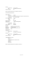
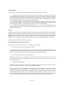
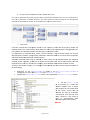
RF‐RXS‐N ‐ Option card for Tridium JACE controllers Receiver Specification: Radio Output: Frequency 2.4GHz 16 channels, automatically selected Direct‐sequence spread spectrum Compliance IEEE 802.15.4‐2006 Aerial Characteristics: Gain 2.0dBi VSWR 2:1 Data Encryption: AES 128 Power Output: +10dBm (10mW @ 50Ω) Analogue Outputs: RF‐RX20 20 x 0‐10Vdc analogue outputs @10mA max. each RF‐RX40 40 x 0‐10Vdc analogue outputs @10mA max. each Analogue Output ranges: Temperature ‐10°C to +70°C RH 0% to +100% Setpoint 0% to +100% Switch 0Vdc = OFF, 10Vdc = ON Power Supply: 24Vac/dc Environmental: Operating: Temperature: ‐10°C to +50°C RH: 0 to 90%, non‐condensing Storage: Temperature: ‐10°C to +80°C RH: 0 to 90%, non‐condensing Country of origin: UK Refer to product datasheets for installation instructions. Page 11 of 83 The RF‐IOM The RF‐IOM has no “intelligence”, but merely acts as local I/O with connectivity to typical HVAC equipment such as fan coil units (FCUs) and variable air volume (VAV) boxes. The RF‐IOM reads its digital and analogue inputs and transmits the values wirelessly to a BMS controller via either a SonNet V2 serial receiver or a SonNet option card receiver. The RF‐IOM receives its output values wirelessly from a BMS controller via either a SonNet V2 serial receiver or a SonNet option card receiver. Additionally, the RF‐IOM has full router functionality. Typically, a simple system will consist of; Battery powered EDs Powered routers (if required) SonNet V2 serial receiver or a SonNet option card receiver RF‐IOMs The EDs (and routers, where applicable) operate in the normal way. Data from the receiver is made available to the controller via a serial link. The SonNet data points are then used by the controller as part of a control strategy, which will typically calculate heating and cooling demands, damper positions etc. These calculated control values will then be passed back to the receiver via the serial link and passed from the receiver over the wireless network to the RF‐IOM. The RF‐IOM outputs are defined as points in the JACE so that their values can be set by the control strategy via the receiver. Note that the RF‐IOM cannot be used with the RF‐RX20 or RF‐RX40 receivers. RF‐IOM Specification: Radio Output: Frequency 2.4GHz 16 channels, automatically selected Direct‐sequence spread spectrum Compliance IEEE 802.15.4‐2006 Aerial Characteristics: Gain 2.0dBi VSWR 2:1 Data Encryption: AES 128 Power Output: +10dBm (10mW @ 50Ω) Power Supply: 24Vac/dc Inputs: 4 x universal inputs; 4‐20mA (loop or externally powered), into 750Ω maximum impedance 0‐10Vdc, into 4k7Ω minimum impedance Resistive, 1.5kΩ min to 60kΩ max Digital, VFC Outputs: 4 x 0‐10Vdc linear, @ 20mA per output LED Indication: Network Data Digital input Housing: DIN Rail H86mm x W58mm x L104mm (excluding aerial) Environmental: Operating: ‐10°C to +50°C Temperature: RH: 0 to 90%, non‐condensing Page 12 of 83 Storage: Temperature: RH: Country of origin: ‐10°C to +80°C 0 to 90%, non‐condensing UK Page 13 of 83 The Rad
dio Network m is compriseed of a rece
eiver, battery powered seensors, RF‐IOMs and A Sonttay® SonNet radio system
nently powereed routers. perman
nsing elementts, accomplishhing both rou
uter and Routerss, though perrmanently powered, can aalso have sen
sensorss functions. Ro
outers, RF‐IOMs and sensoors can eitherr communicatte directly witth the receive
er or via other ro
outers. RF‐IOM
Ms and routers are requireed to be perm
manently powered as they need to stay “awake” at all times to allow signals from “child” node s to be instan
ntly forwarded to their “paarent” nodes.. Battery powereed sensors onlly “wake” for vvery short perriods to send data. matic above, rrouters R2 to R7 have In the schem
5 children each, e
all batteery powered sensors. Their parentt is the receiiver. Router R1 R has 6 children and
d R8 has 4 chhildren, givingg a total number of network devvices of 50, including the receiver.. pport a maximum of 16 ddirectly conne
ected “child” devices, of w
which only 12
2 can be The recceiver can sup
battery powered nod
des, plus up to
o 4 routers. Ms and routerss can support a maximum of 16 directlyy connected “cchild” devicess, of which on
nly 8 can RF‐IOM
be batteery powered nodes, plus up
p to 8 routerss. m depth There can bbe a maximum
of 8 laye rs of routerrs in a m of 150 network annd a maximum
nodes per nnetwork with the RF‐
RX series off receivers. Page 14 of 83
Note th
hat battery po
owered device
es can only rooute their sign
nals to the recceiver directlyy or through RF‐IOMs and rou
uters, and not through othe
er battery pow
wered device
es. planning a Son
nNet radio network, it is re commended tthat the Sonta
ay® SonNet Sitte Survey Kit be used. When p
This easy‐to‐use pacckage allows installers to ttest signal strrengths betwe
een locations s required forr battery d the receiverr prior to instaalling the full system. It can
n also identifyy whether rou
uters are powereed sensors and
needed
d to ensure reeliable commu
unications beetween all devvices on the n
network backk to the receivver. This removees any guessw
work from planning a systtem and allow
ws the installer to order exactly and only o
the devicess required. Net radio senssor system Sitte Survey Kit Q
Quick Start Gu
uide and The Sontay® SonN
Net radio See thee Sontay® SonN
sensor ssystem Site Su
urvey Kit Man
nual for full deetails. onsiderationss Networrk Planning Co
planning a SonNet radio system, it is alw
ways worth co
onsidering the
e placement oof routers, and
d should When p
be capaable of handlin
ng the conseq
quences of a rrouter failing o
or being dama
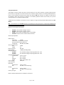
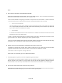
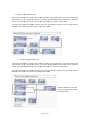
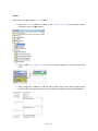
aged. Example: with a require
ement for 16 EEDs: Consideer a network w
ed, as 16 1. At least one rouuter is require
onnected ED
Ds will exce
eed the directly co
maximum limit of 12. Four EDs will be orphaned.
s
router (R1) will wo
ork, but 2. A single gives no red
dundancy if thhe router shou
uld fail. Page 15 of 83
uters, R1 3. Optimal networrk uses 2 rou
and R2. f
the 4. If either of thhe routers fail, maintained, as the 2 network can still be m
orphaned EDs E
can re‐rroute via the other router. Page 16 of 83
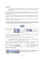
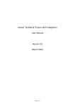
The Radio System The radio system used by the Sontay SonNet devices is divided into 3 sections or ‘layers’. 1. The radio layer is where physical control of the radio signal is done. This conforms to international standard 802.15.4, and determines the frequency of the radio signals, the number of ‘channels’ available for use, the bandwidth and power level of the signal etc. There are 16 channels available, and the best one is automatically selected by the receiver. The frequencies used are in the ISM (Industrial, Scientific and Medical) 2.4GHz band, with a maximum data rate of 250kb/s. 2. The network management layer is where the self‐healing tree functionality is run, which controls network topology. ‘ZigBee’ is an example of a network management MESH protocol. SonNet does not use ZigBee, but instead uses a ‘self‐healing tree’ protocol to control network topology. 3. The application layer determines what the device does – i.e. makes it a temperature sensing device, a router or a receiver. SonNet devices use specific applications, and include features such as configuration properties. Security All SonNet system devices have the same, unique network identifier. Only devices with the correct ID will be allowed to join the network. The ID used by system devices is different from the ID used for site survey kit (SSK) devices. Hence, SSK devices cannot join a system network and vice versa. When a SonNet system network has been formed, it can be ‘locked’ to prevent any unauthorised devices joining, even if they are SonNet devices. The CMS can be used to subsequently authorise extra SonNet system devices if required. All data transmitted by SonNet devices is encrypted. How the Self‐Healing Tree Network is Formed The network is formed based on 3 rules, and in a specific order of priority. 1. How many ‘tiers’ a device is away from the receiver. If a device can communicate directly with the receiver, it will, even if the link quality is poorer than if it went through a router. If a device has a choice of more than one router, it will always choose the router closest to the receiver (the least number of tiers away), even if the link quality is poor. 2. The number of ‘child’ devices a router already has. A RF‐IOM or router can have a maximum of 16 ‘children’. If a device has a choice of more than one router of the same tier level, it will always choose the router with the least number of children, even if the link quality is poor. 3. Signal Strength (link quality). Finally, if a device has a choice of more than one RF‐IOM or router of the same tier level and the same number of children, it will choose the router with the best link quality. If, for any reason, a device (ED, RF‐IOM or router), loses its preferred path back to the receiver, it will automatically search for an alternative – still obeying the 3 rules above in sequence. If, despite employing Direct Sequence Spread Spectrum (DSSS) techniques, interference on the currently occupied channel prevents communications, the receiver will automatically look for another channel which is clear. All other devices, having lost their links to the receiver, will then also automatically scan the 16 channels until they find the receiver again, and the network will re‐form without user intervention. Page 17 of 83 Propagaation of Radio
o Signals in Bu
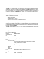
uildings opagation of m
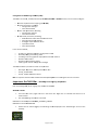
microwave rad
dio signals in aa building can be affected in
n several wayss: The pro
Attenua
ation en it passes thhrough air. Siggnals are Radio signal strength is atttenuated whe
much more when passing through otther media, such as attenuated m
materials typpically used in
n construction, such as brrick, stone, wo
ood and especially steeel. Reflectiion Re
eceiver
ng, radio signa
als can take m
many paths from f
the Depending oon the buildin
transmitter too the receiverr, rather than just one singlee path. h
the effe
ect of cancellling each oth
her out, ‘Multipath’ ssignals can have reducing oveerall received ssignal strength
h. Transmittter
Scatteriing uce its signal sstrength. Scattering th e radio signal can also redu
Page 18 of 83
Extension Aerials When using the RF‐AERIAL‐PM2 or RF‐AERIAL‐PM5 extension aerials, it is important to observe some basic rules for siting and mounting. 1. Always ensure there is a much clear space around the aerial as possible. 2. Generally speaking, where possible mount the aerial as high as possible on the same floor as the routers and EDs 3. Don’t mount between metal surfaces (for example steel I‐beams) in ceiling spaces 4. Wherever possible, mount the aerial on a metal ground plane (such as the top of a metal panel) 5. The coaxial cable used for the RF‐AERIAL‐PM2 or RF‐AERIAL‐PM5 extension aerials is semi‐rigid and should not be bent at too sharp an angle or too tight a radius. It is recommended that the minimum bending radius is 5cms 6. Always mount the aerial vertically. This produces the optimum radiation pattern and signal strength 7. Extension aerials can be used with receivers and RF‐IOM modules. 8. Aerial extensions should not exceed 5m to prevent excessive loss of signal. Page 19 of 83 a.
b.
c.
d.
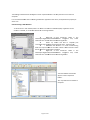
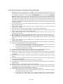
FAQs How is access to the sensor network locked at the CMS? Nodes are only allowed to join the network if the receiver allows them to. This is true even if the nodes are identified as SonNet Nodes and have the correct encryption key. There are two methods to configuring the receiver to accept nodes on to the network. In order to authorise a node the CMS must be in administration mode (File‐>Switch Admin Mode must be ticked). •
Auto Commissioning Mode The CMS allows the receiver to be switched to auto commissioning mode. In this mode any nodes that can correctly identify themselves as SonNet nodes will be allowed to join the network. Any nodes that do join will be added to the CMS textual display. •
Manual Mode In manual mode individual nodes can be removed from or added to the authorised node list from the CMS. Manual mode is the default mode. A node can then be authorised by Options‐>Authorise (add) a new node or selecting the same option on the right click menu in the Textual or Graphical parts of the application display. The user must type the MAC address (found on the PCB or product housing) of the new node into the dialog that appears and can also give the node a textual name (up to 10 characters) Why do some menu items disappear if the CMS application is idle for some time? The CMS has a timeout that operates when in Admin mode. If there is no activity for some time the CMS application will exit admin mode and some admin menu items will be disabled or removed. The timeout can be set in Options‐> Change Idle Time. Admin mode can be entered again in File‐>Switch Admin Mode The CMS application right click menu has stopped being provided. Why? This probably means that the CMS has detected that the receiver has been disconnected from the PC. This will be indicated on the status bar at the bottom left side of the CMS application window "Receiver Disconnected". In this state many of the CMS facilities are disabled until the Receiver is connected again. How are the network node names stored, are they persistent? The node names are stored in the receiver’s non‐volatile memory. Therefore these will be the same even if a different PC is attached to the system, or the receiver is reset or power cycled. Page 20 of 83 e.
f.
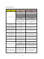
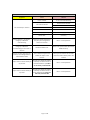
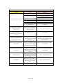
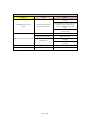
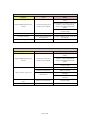
In the CMS application, what is an “Unknown” node? The application will list all nodes that have been added to the system as unknown initially. As soon as a node is added (either manually or by the use of auto commissioning mode) a request is sent to it to establish what type of node it is and what capabilities it has. As a result a node will be categorized as unknown until a response is received from it. If the node remains off‐line or does not respond for any other reason it will remain in this category. The CMS will send a request each time it is started if there are still unknown nodes in the system. What are the ranges of the RF‐RX20 and RF‐RX40 receiver 0‐10Vdc outputs? Temperature ‐10°C to +70°C RH 0% to +100% Setpoint 0% to +100% Switch 0Vdc = OFF (False) 10Vdc = ON (True) 0 – 2000ppm CO2 Fan Speed 0Vdc = Off 2.5Vdc = Lo 5.0Vdc = Med 7.5Vdc = Hi 10.0Vdc = Auto VFC 0Vdc = OFF (False) 10Vdc = ON (True) PIR 0Vdc = Unoccupied (False) 10Vdc = Occupied (True) Page 21 of 83 Configu
uration & Mon
nitoring Softw
ware (CMS) MS is connecteed, via USB, to
o a Sontay® RF‐‐RX20, RF‐RX4
40 or RF‐RXS receiver, and is used to con
nfigure: The CM
R
Receiver outp
put channel mapping (not R
RF‐RXS) E
ED node parameters, includ
ding; o Configuration settings o User‐defined labels R
Router node p
parameters, in
ncluding; o Configuration settings o User‐defined labels R
RF‐IOM node parameters, iincluding; mission time
o Defaultt measurement data transm
o Send o
on value changge settings o Analoggue output fall‐back values
o Input aalarm levels o User‐defined labels or; It can also be used fo
Enabling or disabling auto
omatic config uration mode
e
dding or remo
oving nodes Manually ad
Providing a text and graphical display oof the wirelesss network
Monitor devvice status
Monitor linkk and battery quality
View logs fo
or receiver con
nfiguration chhanges MS installation procedure installs 3 compoonents: The CM
Microsoft® SSQL Server 2005 Express Eddition SP2
Sontay® Son
nNet CMS
Sontay® devvice USB device drivers o the receiver. NB It is important that the CMS installation be ccompleted priior to connectting the PC to Important: DO
O THIS FIRSST – Disablin
ing Driver Sig
gning Verificcation o installing CM
MS, driver signing may needd to be disable
ed. Prior to
ws 7 64‐bit Window
From the Sttart menu, tyype cmd.exe i n the search bar. Right click on cmd.exxe and choose run as administrator. Run the follo
owing comma
ands in the shhell. doptions DDISA
ABLE_INTEGRIITY_CHECKS
bcdeditt.exe ‐set load
bcdeditt.exe ‐set TESTTSIGNING ON Restart the PC. When lo
ogged, the fo llowing will be b displayed in i the bottom
m right corne
er of the desktop: Page 22 of 83
ws 8 Window
Place the m
mouse (do nott click) at the bottom‐rightt‐corner of the screen and wait for the pop‐out bar to appear, Then click the Settings ( Gear icon). Click Changee Pc Settings. Click “General”. estart now” u nder “Advanced Startup”.
Scroll down, and click “Re
bleshoot”. Click “Troub
nced Options”” Click “Advan
Click “Windows Startup SSettings” Click Restartt. C restarts, sele
ect “Disable D
Driver Signaturre Enforcemen
nt” from the l ist. After the PC
matically The PC will rreboot autom
ws 8.1 Window
mouse (do nott click) at the bottom‐rightt‐corner of the screen and wait for the pop‐out Place the m
bar to appear. o type 'Advannced Start Up' and you should see 'Channge Advanced
d Startup In the Searcch Box start to
Options' Clicck on it. Click 'Restarrt Now' Underr Advanced Sttart Up' C restarts, sele
ect “Disable D
Driver Signaturre Enforcemen
nt” from the l ist. After the PC
matically The PC will rreboot autom
ws 10 Window
e power optionns menu from
m the Start Me
enu. Select “Resttart” from the
Hold down tthe SHIFT key while you clicck Restart. omputer has rebooted, chooose the “Trou
ubleshoot” option. Once the co
ptions available, choose “Addvanced optio
ons” From the op
ptions available, choose “Sttartup Settings” From the op
n Click the “Reestart” button
omputer has restarted, a llist of startup
p settings is available. a
“Dissable driver signature After the co
enforcemen
nt”. Choose “D
Disable driver signature enfforcement” by
y pressing the F7 key. matically The PC will rreboot autom
oft® SQL Serveer 2005 Express Edition SP22 is installed ffirst, if not alre
eady installedd, followed byy Sontay® Microso
®
SonNett CMS and finaally the Sontayy device USB device driverrs. hat there is an a issue with SQL Server 22005 Express Edition SP2 and MSXML 6 SP2 (see Microsoft M
Note th
Knowleedge Base artiicle KB954459
9 for full detaails). To overccome this, the
e CMS installaation will offe
er to run ndows Installeer Cleanup Utility to uninsstall MSXML6 SP2. When tthis message appears, clickk on the the Win
<Install> button. Page 23 of 83
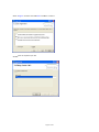
Installin
ng CMS NB It is importannt that the CMS b completedd prior to con
nnecting installation be the PC to th
he receiver. Ennsure that th
he PC on which you are installingg the CMS is NOT o the receiverr until the installation connected to
is complete.
The CMS is compatibble with Microsoft® ndows 7. Windows XP SP2 or later, VVista and Win
i
CCD comes with w
all The CMS installation required pro
ogramme filees and drive
ers, and includes Microsoft® SQL Seerver Express SP2. W
NB You must be loggged in to Windows ministrator leevel user acccount to with an adm
® install the Sontay
S
CMS and Microso
oft® SQL Server Express SP2. P2 is not If SQL Server 2005 Expreess Edition SP
already installed on youur PC, the fo
ollowing will be executeed. installation w
ess Edition SP22 installation window appe
ears, read thee EULA and th
hen click When tthe SQL Serveer 2005 Expre
the <Acccept> button. QL Server 20005 Express Edition SP2 The insttallation of SQ
continues until complete. display The nexxt step in the iinstallation prrocedure will d
the “We
elcome to the
e SonNet CMS S Setup Wizard
d. Click the <Ne
ext> button to
o continue. Page 24 of 83
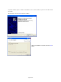
Select <<I Agree> and then click the
e <Next> buttoon to continue. C.
SonNett files are copied to your PC
Page 25 of 83
A separrate window opens to allo
ow the installlation of the 2 device drivvers required for the USB receiver connecttion. To instaall these, click the <Next> button to contiinue. en the installa
ation is compllete, click the <Close> Whe
buttton. Page 26 of 83
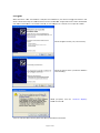
Startingg CMS f
connecte
ed to a USB pport and switcched on, the device managger will detecct a new When aa receiver is first device. Follow these steps to insta
all the drivers for the receivver. NB ‐ This p
procedure willl need to be ffollowed me a new receeiver is connected to the PCC, as each USB
B port on a receiver has a uunique ID num
mber. each tim
ption shown ((“No, not this time”) Select the op
Select the option shown (“Install the ssoftware automaticallly”) n prompted, click the <Continue Anyway> A
When
butto
on to continue
e. There aare 2 drivers to
o be installed,, follow the saame procedurre for both drivers. Page 27 of 83
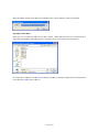
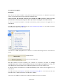
When tthe CMS is started, the PC ccom port connnected to the receiver USB port needs too be defined. Importiing a Saved Laayout o ask if the uuser requires a saved XML layout file too be imported
d. This is When ffirst run, the CMS may also
useful iff an existing laayout has bee
en saved on a site where the PC running CMS has beenn replaced. quired, click th
he <Cancel> bbutton to conttinue, otherwiise navigate too the saved layout file If no layyout file is req
to and cclick the <Opeen> button im
mport it. Page 28 of 83
The CM
MS Desktop En
nvironment MS desktop is d
divided into 2 parts, a textuual hierarchicaal display The CM
p” display. and a graphical “map
Page 29 of 83
anel, from thhe menu bar choose To ennable the texxt display pa
<View
w> then <Texttual Display>
phical display panel, from tthe menu barr choose To ennable the grap
<View
w> then <Grap
phical Display> Loggingg On as an Administrator make any changes to deviice configurattion or to crreate or To m
modiffy the graphical display, you must first log on
n as an admi nistrator. To do d this, from the menu baar choose <File> then ode> <Swittch Admin Mo
ox appears. Ty
ype in your a dmin level pa
assword. The login bo
NB The de
efault admin level passw
word is admiin (case sensitive). TThis can be cha
anged once yoou have logge
ed in. Changin
ng the Admin
nistrator Passw
word he admin passsword, from tthe menu barr choose To change th
<File> then
n <Change Password>. Enter the existing password, en
nter your new
w password aand confirm. Click C
the <Update> bu
utton to submit the change,, or click <Can
ncel>. Page 30 of 83
Auto Co
ommissioningg Mode IMPORTTANT! s
netwo
ork is being ccommissioned
d for the first time, it is addvisable to place the When aa new radio system receiver in automaticc commissioning mode for tthe network tto form. will not allow
w any nodes oor routers to join the If this is not done, tthe network iis treated as secure, and w
ng the device MAC addresss). networrk without maanually authorising each deevice (this invvolves enterin
ork in automaatic commissiioning mode, ensure you are logged on o as an To placce the receiveer and netwo
adminisstrator. he menu barr, select <Opttions> and cl ick <Auto‐com
mmissioning Mode>. A ticck beside thiss option From th
denotess that this speecial mode is e
enabled MS displays whether w
the rreceiver is in auto‐commissioning modee or if the network is The staatus bar of CM
locked. work Locked Netw
ng mode Auto‐‐commissionin
When tthe network has formed completely, and all devicces can be viewed in thee CMS, it is strongly recomm
mended that the receiver and networkk be taken ou
ut of auto‐com
mmissioning m
OT try to mode. Do NO
make co
onfiguration cchanges while
e in auto‐comm
missioning mo
ode. This may cause netwo rk errors. oning mode, ensure you aare logged on as an To takee the receiver and network out of auuto‐commissio
adminisstrator. he menu bar,, select <Options> and clicck <Auto‐com
mmissioning Mode>. M
There should not be b a tick From th
beside tthis option, an
nd denotes th
hat this speciaal mode is disaabled. work and ensu
ures that unauuthorised nod
des cannot join the networkk. This seccures the netw
Page 31 of 83
To prevvent leaving CMS in an adm
min state whenn not supervissed, the admin log‐in statuus automatically times out afteer the time seet in the “Chan
nge Idle Time ” setting expires. To disable
e this feature (not recomm
mended), or to ch
hange the timeeout value, from the menuu bar choose <
<Options> then <Change Idlle Time> he Enable Idle Time Out boxx disables adm
min timeout feature. The tiimeout value can also Removiing the tick th
be chan
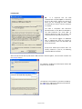
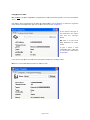
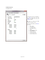
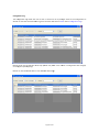
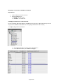
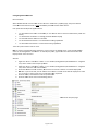
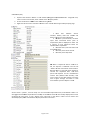
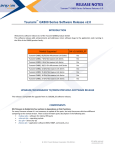
nged. List Devvices eft of the winddow, a list of all devices on
n the networkk can be found
d. These In the ttext display paanel on the le
devicess are divided in
nto 4 main categories, receeiver, routers, RF‐IOMs and battery poweered sensor no
odes. EDs
Receiver Routers
RF‐IOMs Each caategory can bee expanded to
o view more d etail or collap
psed to hide detail. which are joining the netwoork for the firrst time, The “Unknown” cateegory is initially populated by devices w
by auto‐comm
missioning or m
manual authoorization. Devices are held in the unknow
wn category until CMS either b
has dettermined the type of device trying to jooin (for examp
ple, a router o
or node) and w
which options, if any, are fitteed (such as seetpoint). When CMS has deetermined thiss information, the device w
will then autom
matically be placeed in its appro
opriate catego
ory. hat for the RF‐IOM, if an input is in an a larm conditio
on, that input will be displaayed in red in the text Note th
display (see screen sh
hot above). Page 32 of 83
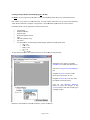
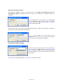
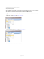
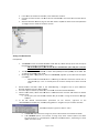
Changin
ng Device Lab
bels o NOT try to m
make configura
ation changess while in auto
o‐commissioning mode. Th is may cause network NB ‐ Do
errors. Each deevice, when first depicted in the CMS, haas a default laabel, such as ““Router1” or ““Sensor2”. To give the router aa more meaniingful label, right click on thhe router and choose <Prop
perties> In the <<Name> box, type in the new
w name you require and cllick the <C
Change> button. NB Theere is a limit of 10 ASCII chharacters forr router names. e a sensor a more To give meaninggful label, rigght click on the sensor and choose rties> <Propert
ew name you rrequire and cllick the <Chan
nge> button. In the <<Name> box, ttype in the ne
NB There is a limit off 10 ASCII characters for sennsor names.
Page 33 of 83
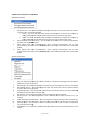
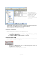
Creating Analogue O
Output Channel Mapping (nnot RF‐RXS) output channe
els while in au to‐commissio
oning mode. T
This may causee network errors. Do NOTT try to map o
asured value, and with options fitted ca
an have up too 4 measured
d values. Each seensor has at least one mea
These vvalues need to
o be “mapped” or assigned to a unique 0
0‐10Vdc outpu
ut channels onn the receiver. Parameeters which can be mapped to an output channel are:
Temperature
midity
Relative Hum
Setpoint levvel
Momentaryy switch statuss
CO2
PIR Status (rrouters only)
VFC status
Value. The following outputt voltages reprresent the fan
n speed statuss; Fan Speed V
o OFF = 0V w = 2.5V o Low
o Meed = 5.0V o Hi = 7.5V o Auto = 10.0V To map these parameeters, first select the senso r (or router w
with sensing element). ect Right‐cclick on the deevice, and sele
<Prope
erties> from thhe drop‐down
n menu. apping> Select the <Analogu e Channel Ma
tab. ect Using tthe <Functionn> list box, sele
which device param
meter to map. Using tthe <Channel No.> list box, select the outtput channel tto map to. Analogue Mapping> M
Click the <Set A
button to accept tthe changes, or the <Close> button to exxit with accep
pting the ng changes. mappin
n for all device
e parameters,, and for all de
evices. Repeat this operation
Page 34 of 83
To remo
ove an analoggue channel m
mapping, follow
w the steps ab
bove, but sele
ect <No Mappping> from the
e <Chann
nel No.> list bo
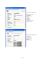
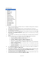
ox. perties Viewingg Device Prop
To view the currrent analoguee output channel ver in the text display. maappings, expand the receive
operties of anny device can be The specific pro
iewed by right
t‐clicking a deevice and selecting vi
<Properties> in
n the drop‐dow
wn menu. Available route
A
er properties aare:
Parent (if applicable) MAC address M
So
oftware versio
on Sttatus Liink Quality Runtime ms
Any active alar
A
Page 35 of 83
Available sensor prooperties are: Parentt (if applicablee) MAC a
address Software version Statuss Link Q
Quality Runtim
me Batterry level Any m
measured valuees Any acctive alarms
Page 36 of 83
Available receiver pproperties are: MAC a
address Software version RF cha
annel used Runtim
me Autho
orised nodes
Changin
ng Device Con
nfigurations on changes w
while in auto‐ccommissioning mode. Thiss may cause network Do NOTT try to makee configuratio
errors. nfigurable parrameters. The
e setting of th
hese can be iimportant forr battery Batteryy powered nodes have con
ect battery liffe. For examplle, if a temperrature sensor in a room is sset up to powereed devices, as these will affe
transmiit its value eveery 10 second
ds, the batteryy life will be le
ess than if the sensor were sset to transmit values every 5 minutes. o each device and how oftten it should ssend values aand still main
ntain the Consideeration should be given to
requireed level of con
ntrol to maxim
mise battery life. Howeverr, setting a tra
ansmission innterval to a hiigh level may result in havingg to wait for the set interrval time to elapse e
before
e current dataa is shown when w
re‐
connecting the CMS to a receiver.. om doesn’t no
ormally changee by a significant amount in
n a few minuttes, RH even le
ess so. Temperrature in a roo
nt values are only sent if the value cchanges by a configurable
e level. The ssame is true for the Setpoin
momen
ntary switch, V
VFC and PIR; d
data is only traansmitted on a change of sttatus (ON or O
OFF). Temperrature, RH annd CO2 can also be configured to sendd on a “siggnificant change of value”. TThese values are also configurable by the aadministrator.
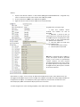
urable Parameeters Configu
w or changge battery powered p
To view
sensor node param
meters, right‐click on r
deevice and select the required <Properties> from thhe drop‐down
n menu. Select the <Configuraation> tab. Measuremeent interval eshold Temperaturee change thre
RH change tthreshold Setpoint thrreshold PIR Off Delaay Clear VFC Coount When aall changes are complete, cclick the <Cha nge> button tto accept the changes, or tthe <Close> button to exit witthout acceptin
ng the changes. Page 37 of 83
Where a CO2 device is to be configgured, the fol lowing configuration settings are availabble; Measureme nt interval Temperaturee change threshold RH change thhreshold CO2 change threshold CO2 Auto caalibration funcction PIR Off Delayy Clear VFC Coount When aall changes are complete, cclick the <Cha nge> button tto accept the changes, or tthe <Close> button to exit witthout acceptin
ng the changes. Page 38 of 83
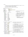
RF‐IOM
M Configuratio
on M Status Tab RF‐IOM
To change the naame of an RF‐‐IOM, In the <Name> box
ox, type in the new me you requuire and click the nam
<Cha
ange> button . NB There is a limit of 10 ASCII charracters for devvice names. <Status> Information displ ayed on the <
tab include; MAC adddress Firmwaree version Parent M
MAC address Status Link qua lity (to parentt) Device ruuntime Current iinput types Current iinput values Current ooutput valuess Page 39 of 83
Changin
ng the input cconfiguration Each off the 4 inputs ccan be set as either; 4‐20mA current (loop pow
wered or 3‐w ire) 0‐10Vdc Ω and 60kΩ)
Resistance ((between the limits of 1.5kΩ
Digital inputt (volt free contact only) To enable or disabble significantt change of va
alue actions, tick or un‐ttick the appro
opriate box forr each input. et a new meeasurement interval, To se
enter the requiired level in the opriate box. appro
nable or disa ble high and
d/or low To en
alarms, tick or un‐‐tick the app
propriate box fo
or each input. m, low alarm or COV To set high alarm
valuess, enter the required leve
el in the appro
opriate box. Notess: 1. Alarm levvels are not available a
where
e an input is sset as VFC 2. The units for alarm levvels and COV are a dependennt on the inp
put type. For example, if ann input is sett to mA, then tthe units for CCOV and alarm levels are also in mA. > button Imporrtant! Click tthe <Change>
after cchanges are m
made. fter making ch
hanges to the input mode jjumpers, the rreset button m
must be presssed for the RFF‐IOM to NB ‐ Aft
update the input mapping. Page 40 of 83
Changin
ng the outputt configuration
n Each off the 4 outputss is fixed as a linear 0‐10Vddc output. n tab. Output values can bee written using the Output Configuration
n output to aa new level, enter to To set an
required voltage inn the app
propriate <Current Values> bbox and click the <Change> button. k Settings Fall‐back
orce the Fall‐back settings can be used to fo
e outputs to ppre‐determined values analogue
if the RF‐‐IOM loses coommunication
ns to the parent receiver andd therefore cannot update correct controol values. Under these ances, it maay be desirrable to circumsta
ensure outputs o
are foorced to 0V (in ( most cases, an OFF state). ed if the NB ‐ Falll‐back values WILL be use
RF‐IOM loses comm
munications to the deration parent receiver. Caareful consid
e given to thee values used. should be
o a new To set a fall‐back outtput value to
nter to requuired voltage in the level, en
appropria
ate <Fall‐bacck Values> box b
and click the <Change> buttton. Page 41 of 83
Manually Authorisin
ng a New Node dditional nod
de to an exissting system, it is strongly recommennded that th
he auto‐
When adding an ad
des to be addded become
es time‐
commisssioning metthod is not used unless the number of new nod
prohibittive. e logged To manuallyy authorise a new node(s),, you must be
on at admiinistrator leve
el. From the menu bar, click on <Options> and a then sele
ect <Authorisee (add) a new
w node> from the dro
op‐down men
nu. e new node, fo
found on the label on You will need to make a note of tthe unique 166‐digit MAC address of the
he new device
e is powered oon. the devvice. Ensure th
Enter this MAC addresss and a deevice label into the e details, appropriate box fields and click <OK> tto submit the
ncel> to discard the informaation. or click <Can
om the Netwo
ork Removiing a Node fro
t network, from the me
enu bar, To remove a node from the click on <Opttions> and th
hen select <D
De‐authorise (remove) node> from the drop‐dow
wn menu. Sel ect the devicce group (routers, RF‐IIOMs or sensors) and thenn select the device by name (label).. Remove> to su
ubmit the deta
ails, or click <CCancel> to disscard the actio
on. Click <R
Page 42 of 83
Using th
he Graphical Map Display a graphical en
nvironment w
which allows users to Apart ffrom the textt hierarchical display, the CMS offers a quickly determine ho
ow the network is functioniing. age set as a baackdrop for the map display
y. By default, there is no graphic ima
u for the map display woould be a floor plan of the environmennt in which the radio A typicaal image to use network has been insstalled. play Backgrou
und Image Setting the Map Disp
administrator r level. To set aa background image for the map display, you must be logged on at a
u bar, click onn <Options> a
and then Frrom the menu
se
elect <Set Background Imaage> from th
he drop‐
do
own menu.
Page 43 of 83
o the image file required
d. Image Browse to
file formats currently suupported are:: Bitmap (.b
bmp) JPEG (.jpg
g) Adding Devices to th
he Map Displa
ay he map displa
ay, simply “draag‐and‐drop” a device from
m the text hieerarchical disp
play onto To add a device to th
phic backgrou
und. the grap
he receiver to the graphic first, thenn routers followed by ba
attery powereed nodes. Liinks are Add th
automaatically generaated, showing the true netw
work architectture. nt icons are used u
to depicct the receiveer, routers and
d battery pow
wered node, making identtification Differen
easy. Th
he icons also d
depict the status of the devvice, and chan
nge to reflect whether a deevice is OK, offf‐line, or in alarm
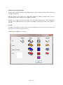
m. Icon Plaan dule of what eeach icon and
d icon colour ccan be quicklyy found from the menu barr, click on <He
elp> and A sched
then seelect <Icons> ffrom the drop‐down menu.. p window is displayed: The following pop‐up
Page 44 of 83
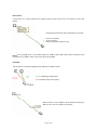
Device Status t map A quickk check on a device statuss can be madde by hovering the mouse cursor over aa device on the display. are device deppendent, but include: Displayed parameters a
Device name (label)
All sensorr values
Battery level (battery devices only) wn in italics, th
his denotes thhat a request for data NB Where link qualitty, hours run and battery leevel are show
ded. has beeen sent to a deevice, but the device has noot yet respond
Link Staatus phically by thee colour of the
e link drawn.
The linkk status is represented grap
Green: Indiccates good linkk quality. Red: Indicatees marginal link quality. A
A quick check on any link sttatus can be m
made by hove
ering the m
mouse cursor over a link on
n the map dispplay. Page 45 of 83
Auto Updating MS can be conffigured to upd
date at a user configurable rate. The CM
<
From thhe menu bar,, click on <Options> and then select <Change Update Time> from the drop‐dow
wn menu. Adjjust the upda
ate time OK> to submitt the change, or click <Cancel> to accordinngly. Click <O
discard tthe change. Auto up
pdating can also be disabled
d. <
From thhe menu bar,, click on <Options> and then select <Change Update Time> from tthe drop‐down menu. Rem
move the tick ffrom the Update> box. Click <OK> to submit tthe change, or click <Auto U
<Cancel > to discard th
he change. Of Data Manual Refreshing O
o NOT try to u
update device
e information while in auto
o‐commissioning mode. Thiis may cause network NB ‐ Do
errors. or network daata can be manually refresshed. This is an importantt feature wheen re‐connecting the Node o
CMS to an existing n
network. a receiver on an existing network, n
When ree‐connecting the CMS to a data wil l only be refre
eshed to the C
CMS as and w
when a device updates mation by tim
med transmission. its inform
To ensu re all data is sent as soon as possible, uuse the Refresh Node Informa tion or Refressh Network Information opttions. node data, rig
ght click on a node and the
en select To manuually refresh n
<Refreshh Node Inform
mation> from the drop‐dow
wn menu. a, right click oon a blank sp
pace (on To manuually refresh network data
the textt or graphicaal display) an
nd then selecct <Refresh Network N
Informa tion> from the drop‐down menu. Page 46 of 83
Commu
unications Logg MS can keep a log of all communicatioons on the ne
etwork. This can c be helpfuul in finding faults f
or The CM
diagnossing network p
problems. munications lo
og is enabled. If you want to
o disable this ffeature, By default, the comm
ptions> and thhen select <Configure From tthe menu bar,, click on <Op
Commuunication Logg> from the drop‐down meenu. Remove the tick from thhe <Enable Communicatio
C
n Log> box. CClick <OK> to
o submit the chaange, or click <Cancel> to discard the chaange. w the commun
nications log, ffrom the mennu bar choose <View> then <Communicaations Log>. A window To view
will app
pear at the bo
ottom of the m
main CMS winndow. To close
e this view, click the cross iin the top righ
ht of the commu
unications log window. ng Display Un
nits Changin
ures in °F inste
ead of °C, clickk on <Optionss> then tick <D
Display Fahrennheit>. To displlay temperatu
er temperatuure values, siggnificant This change affeccts mouse‐ove
es, temperature values show
wn in the hierarchical chan ge limit value
text ddisplay and prrint preview.
Page 47 of 83
Configu
uration Log nfiguration lo
og allows the user to view a concise list of any chan
nges made too the configurration of The con
devicess. To view the communicatio
ons log, from the menu barr choose <View> then <Connfiguration Log>. Results shown can be filtered to sshow only speecific “key fiellds” such as w
when a config uration was cchanged, ogue output m
mappings. or analo
Results can also be fiiltered within a user‐definaable date rangge. Page 48 of 83
Using C
CMS to Docum
ment a Wireless Network Saving aand Opening Layouts d, it is very usseful to save the graphical map layout tto use as a re
eference When aa network is ccommissioned
and as tthe basis for ccomparison w
when checkingg the current sstatus of netw
work topology. ords the backd
drop (if used)) and the possition and size
e of each devvice icon on the t map Saving a layout reco
display. To save a layout, clickk on <File> then <Save Layout> To open
n a saved layo
out, click on <F
File> then <<Load Layo
out> uts can be form
med as a referrence. A library of site layou
Page 49 of 83
Receiveer Print Previeew e hierarchical display, right‐click on To geneerate a comprrehensive textt document off network devvices, from the
the receeiver object, aand from the menu select <<Print Pre
eview>. ment is autom
matically gene
erated, which can be printe
ed on paper fo
or an O&M m
manual, or to .PDF file, A docum
for exam
mple. Page 50 of 83
SonNett‐Tridium JACE Driver Actio
on Menus Networrk Action Menu i.
ii.
iii.
iv.
ommand deteermines wheth
her the driver can only findd nodes if the receiver Set System Lock – This co
is placed in auto‐commissioning modee ned to a receeiver (for exam
mple, by a. FALSE = The driver will find nodes already commission
ntay CMS) witthout having tto put the receiver into auto commissionning mode. Son
b. TRU
UE = The drive
er will not fin d nodes alreaady commissio
oned to a receeiver (for exam
mple, by Son
ntay CMS) witthout having tto put the receiver into auto commissionning mode. Assert Seriaal Card Comm
munications – This comman
nd automatica
ally sets up seerial commun
nications parameters for the RF‐RX
XS receiver ot1 Communnications – This T
command automati cally sets up serial Assert Opttion Card Slo
communications parameters for the R F‐RXS‐N optio
on card receivver connectedd to slot 1 on tthe JACE (COM3) ot2 Communnications – This T
command automati cally sets up serial Assert Opttion Card Slo
communications parameters for the R F‐RXS‐N optio
on card receivver connectedd to slot 2 on tthe JACE (COM4) Receiveer Action Menu i.
ii.
iii.
iv.
v.
vi.
vii.
viii.
ix.
x.
Ping – This ccommand req
quests the recceiver runtime
e, as a method on checkingg comms, butt doesn’t update the receiver runtime field mand requestss the receiverr runtime and updates the rreceiver runtime field Get Runtimee – This comm
Get Softwarre Version – T
This commandd gets the major and minorr versions of tthe receiver firmware and stores tthe result as p
properties De‐authorisse Node – Thiss command dee‐authorises aand removes the receiver ffrom the netw
work (NB Only works when auto co
ommissioning is off) mand refreshess all data, excluding the “pa
arent” properrty Get All Dataa – This comm
Get RF Channel – This co
ommand getss the current 2.4GHz RF ch
hannel (valid channels are 11 – 26 inclusive) o Commissioning Mode – Thhis command sends a request to enable auto commisssioning Enable Auto
Disable Auto
o Commission
ning Mode – TThis command
d sends a requ
uest to disablee auto commissioning Authorise Node N
– This command is uused to manually authorise
e a node or nnodes (as opp
posed to using auto ccommissioningg) Map Netwo
ork – This com
mmand is usedd to discover aand update the parent nodee of all device
es on the network Page 51 of 83
Action Menu Router A
i.
ii.
iii.
iv.
v.
vi.
vii.
viii.
ix.
x.
xi.
quests the roouter runtime, as a method
d on checkingg comms, but doesn’t Ping – This command req
update the router’s runtime field mand requestss the router’s runtime and updates the rruntime field Get Runtimee – This comm
Get Softwarre Version – T
This commandd gets the maajor and mino
or versions off the router firmware and stores tthe result as p
properties De‐authorisse Node – This command dde‐authorises and removess the router frrom the netw
work (NB Only works when auto co
ommissioning is off) mmand refresshes all the data d
specific to the selectted router, excluding Get All Datta – This com
“parent” pro
operty Get Parent LQI – This co
ommand gets radio link strrength (LQI = Link Quality Index) to the
e node’s parent Configuration
n – This comm
mand requests the following
g configuratio n properties; Get Sensor C
a. Has Temp – Whe
ether the nodde has a temperature senso
or fitted her the node hhas an RH sensor fitted b. Has RH – Wheth
Whether the nnode has a settpoint adjustm
ment pot fittedd c. Has Setpoint – W
hether the nodde has a mom
mentary switch
h fitted d. Has Switch – Wh
ween transmission of meassurement valuues e. Meeas Interval – The time betw
f. Sigg Temp – The
e significant c hange in tem
mperature which results in the measure
ed value beiing transmitte
ed immediate ly g. Sigg RH – The significant chhange in RH which results in the meeasured value being transmitted imm
mediately he significant change in setpoint which results in the m
measured valu
ue being h. Sigg Setpoint – Th
transmitted imm
mediately al time betw
ween transmisssion of Set Measurrement Interval – This c ommand setts the norma
measuremeent values [Lim
mits: 10 to 9000 seconds] Set Significaant Temperatture – This coommand setss the significa
ant change inn temperaturre which results in the measured vvalue being traansmitted imm
mediately [Lim
mits: 0.1°C to 1.0°C] measured Set Significaant RH – This command setts the significaant change in RH which ressults in the m
value being transmitted immediately [[Limits: 3% to 10%] – This commannd sets the siggnificant chan
nge in setpoinnt which results in the Set Significaant Setpoint –
measured vvalue being tra
ansmitted imm
mediately [Lim
mits: 1% to 25
5%] Page 52 of 83
xii.
xiii.
xiv.
xv.
xvi.
Set CO2 Autto Calibration – This comm and enables aautomatic basseline calibrattion (ABC) for the CO2 sensor elem
ment. Over a p
period of 24 hhours, the sen
nsor system re
ecords CO2 levvels, and once per 24 hours, the lowest level (which is asssumed to be during a period of no occcupancy) is used to put at 400ppm
m. calibrate thee sensor outp
Set CO2 Maanual Calibrattion – This coommand perfforms a manu
ual calibrationn of the CO2
2 sensor. Ensure amb
bient CO2 is att 400ppm befoore performin
ng this comma
and. Set CO2 Sign
nificant Setpo
oint – This com
mmand sets th
he significant change in CO
O2 which results in the measured vvalue being tra
ansmitted imm
mediately [Lim
mits: 100ppm
m to 800ppm, 220ppm steps,, default = 400ppm] when the PIR element Set PIR Off Delay – This ccommand setts the off delaay, which starrts counting w
[
10 seeconds to 30 minutes, 10 second stepss steps, default = 30 detects no occupancy. [Limits: seconds] Count – This command cleaars the VFC in
nput counter. See also The VFC Activatio
on count Clear VFC C
Point on pag
ge 66. M Action Menu
u RF‐IOM
i.
ii.
iii.
iv.
v.
vi.
vii.
viii.
ix.
x.
xi.
Ping – This command req
quests the RF ‐IOM runtime
e, as a method on checkingg comms, butt doesn’t update the RF‐IOM’s runttime field mand requestss the RF‐IOM’s runtime and
d updates the e runtime field
d Get Runtimee – This comm
Get Softwarre Version – T
This commandd gets the maajor and minor versions of tthe RF‐IOM firmware and stores tthe result as p
properties De‐authorisse Node – Thiss command d e‐authorises and removes the RF‐IOM ffrom the netw
work (NB Only works when auto co
ommissioning is off) mmand refresshes all the data d
specific to the selectted router, excluding Get All Datta – This com
“parent” pro
operty Get Input Configuration
C
– This comm
mand refresh
hes all the data specific tto the RF‐IOM input configuratio
on Get Output Configuration – This com
mmand refreshes all the da
ata specific too the RF‐IOM
M output on configuratio
Set Input Configuration
n – This com
mmand send
ds any chang
ges made too the RF‐IOM
M input on configuratio
Set Output Configuratio
on – This co mmand send
ds any chang
ges made to the RF‐IOM output on configuratio
Get Child No
ode List – Thiss command geets radio link strength (LQI = Link Qualityy Index) to the
e node’s parent ommand gets radio link strrength (LQI = Link Quality Index) to the
e node’s Get Parent LQI – This co
parent Page 53 of 83
Sensor A
Action Menu i.
ii.
iii.
iv.
v.
vi.
vii.
viii.
ix.
x.
Ping – This command re
equests the E D’s runtime, as a method on checking g comms, but doesn’t update the router’s runtime field mand requestss the ED’s run
ntime and upd
dates the runttime field Get Runtimee – This comm
Get Softwarre Version – T
This commandd gets the maajor and minor version of thhe ED’s firmw
ware and stores the reesult as prope
erties De‐authorisse Node – Thiss command d e‐authorises and removes the ED (NB O
Only works wh
hen auto commission
ning is off) Get All Dataa – This comm
mand refreshees all the dataa specific to th
he selected ED
D, excluding ““parent” property Configuration
n – This comm
mand requests the following
g configuratio n properties; Get Sensor C
a. Has Temp – Whe
ether the nodde has a temperature senso
or fitted her the node hhas an RH sensor fitted b. Has RH – Wheth
Whether the nnode has a settpoint adjustm
ment pot fittedd c. Has Setpoint – W
hether the nodde has a mom
mentary switch
h fitted d. Has Switch – Wh
ween transmission of meassurement valuues e. Meeas Interval – The time betw
f. Sigg Temp – The
e significant c hange in tem
mperature which results in the measure
ed value beiing transmitte
ed immediate ly g. Sigg RH – The significant chhange in RH which results in the meeasured value being transmitted imm
mediately he significant change in setpoint which results in the m
measured valu
ue being h. Sigg Setpoint – Th
transmitted imm
mediately al time betw
ween transmisssion of Set Measurrement Interval – This c ommand setts the norma
measuremeent values [Lim
mits: 10 to 9000 seconds] Set Significaant Temperatture – This coommand setss the significa
ant change inn temperaturre which results in the measured vvalue being traansmitted imm
mediately [Lim
mits: 0.1°C to 1.0°C] measured Set Significaant RH – This command setts the significaant change in RH which ressults in the m
value being transmitted immediately [[Limits: 3% to 10%] – This commannd sets the siggnificant chan
nge in setpoinnt which results in the Set Significaant Setpoint –
measured vvalue being tra
ansmitted imm
mediately [Lim
mits: 1% to 25
5%] Page 54 of 83
xi.
xii.
xiii.
xiv.
xv.
xvi.
xvii.
xviii.
Get Battery Level – This command requests the battery status Get Battery Runtime – This command requests the ED’s battery runtime Get Parent LQI – This command get link strength (LQI = Link Quality Index) to the node’s parent Set CO2 Auto Calibration – This command enables automatic baseline calibration (ABC) for the CO2 sensor element. Over a period of 24 hours, the sensor system records CO2 levels, and once per 24 hours, the lowest level (which is assumed to be during a period of no occupancy) is used to calibrate the sensor output at 400ppm. Set CO2 Manual Calibration – This command performs a manual calibration of the CO2 sensor. Ensure ambient CO2 is at 400ppm before performing this command. Set CO2 Significant Setpoint – This command sets the significant change in CO2 which results in the measured value being transmitted immediately [Limits: 100ppm to 800ppm, 20ppm steps, default = 400ppm] Set PIR Off Delay – This command sets the off delay, which starts counting when the PIR element detects no occupancy. [Limits: 10 seconds to 30 minutes, 10 second steps steps, default = 30 seconds] Clear VFC Count – This command clears the VFC input counter. See also The VFC Activation count Point on page 66. Page 55 of 83 Managiing a Tridium JACE SonNett Wireless Nettwork Requireements CE 2xx series o
or 6xx series 1. Tridium JAC
Workbench 2. Niagara AX W
a. RF‐RXS ‐ V3.5.34 or later or later b. RF‐RXS‐N ‐ V3.6.43 o
ng the SonNet Driver to a T
Tridium JACE
Installin
download a co
opy the SonNeet driver file ““sonnet.jar” frrom www.sonntay.com and If not pre‐installed, d
ules> folder on
n the PC runn ing Niagara W
Workbench. Fo
or example; copy it to the <Modu
<C:\Niaagara\Niagaraa‐3.5.34\modules> 1.
2.
Start Niiagara Workbench and log into the JACE platform From th
he platform trree, open <Sofftware Managger> Page 56 of 83
3.
4.
5.
From th
he list of modules and driveers, locate and
d select <sonn
net> Click th
he <Commit> button. The ddriver will be installed. NB ‐ this action w
will cause the JACE to reboot.. After th
he JACE has re
ebooted, log i nto the JACE station. Expan
nd the stationn tree and exp
pand the <Configg> branch to show the <Drivvers> branch. Adding a SonNet Network uisites: Prerequ
The RF‐‐RXS must be connected too COM1 of the
e JACE by a se
erial cable (9‐ pin D male to
o 9‐pin D female)). Do not use a
a null modem
m serial cable. o NB The RS‐2
232 port of th
the RF‐RXS wiill not commu
unicate if the e USB port on
n the RF‐
RXS is conne
ected. The RF‐RXS‐N should be installedd in either Slot1 (COM3) or o Slot2 (COM
M4) of the JA
ACE. See et option cardd” “Installing the SonNe
pply polarity, switch on the
e RF‐RXS, or p
power up the JACE with the option Observing power sup
card fittted. o Observe the
e red networkk LED. If it is b
blinking on an
nd off it meanns the receiver has no child device
es yet, if it is on steadily then the receiver already hhas at least one o child node. 1. Double‐clickk the <Driverrs> folder in the <Station
n\Config > navigation treee to open the
e Driver Manager wiindow. Click the <New> buttton. 2. From the <TType to Add> drop‐down boox, scroll dow
wn and select <
<SonNet Netw
work> OK> button, en
nsure the new
w driver is enaabled and then click the <O
OK> button to add the 3. Click the <O
network driver. he new SonNeet network may m be shown
n in orange inn the Driver Manager M
a. At this point, th
ndow. win
he default communicatioons parameters for the receiver, right‐click on the 4. To set th
<SonNetNettwork> folderr in the <Statioon\Config\Driivers> navigation tree, thenn select <Actio
ons> The Nettwork System right‐click <Action> menu a. If aan RF‐RXS seriial receiver is being used, select <Assert Serial Card Coommunication
ns> b. If an a RF‐RXS‐N option card receiver is being used, select <Asserrt Option Card Slot1 Communications> or <Assertt Option Card
d Slot2 Comm
munications>, depending on o which opttion card slot is used. Page 57 of 83
When the coommunications parameters have been se
et, the ould new SonNett network sho
look similar to this. In the
e SonNet Devvice Manager ould be window, thee receiver sho
shown in whhite. d “Unknown” are created aautomatically. Note Thee default foldeers “Receiver””, “Routers”, ““Sensors” and
thaat the “Discovver” button ha
as no functionnality in the So
onNet Device Manager. ng. Thee new SonNett network is now ready for commissionin
Commissioning a SonNet Network onNet networrk can be commissioned in 2 ways using tthe JACE drive
er; A So
1. An exissting networkk, where the receiver alreaady has child nodes joinedd to the receiver (for example, where the
e network ha s been comm
missioned usin
ng CMS or thhe receiver has been CE to another)) moved from one JAC
pletely new ne
etwork, wheree the receiverr has no child nodes 2. A comp
ork Commissioning an Exxisting Netwo
n existing netw
work, where rrouters and se
ensor end devvices (EDs) havve already joined the To ccommission an
receeiver’s networrk, requires ve
ery little manaagement. 1. Right‐click on the <SSonNetNetwoork> folder in the <Station
n\Config\Driveers> navigation tree, Actions> then <Set System Lock> select <A
2. Using the drop‐down list, select “Faalse” and then
n click OK. Page 58 of 83
The exissting networkk devices will a
appear in theiir respective ffolders. This m
may take seve ral minutes to
o compleete. hat when all e
existing nodess have appearred in the driver, the System
m Lock properrty be It is recommended th
set to TTrue. ew Network Commissioning a Ne
nsor end devicces (EDs) are ppresent on the To ccommission a new networkk, where no roouters and sen
receeiver’s networrk, or to add n
new devices too an existing n
network. 11.
Right‐click on the t
<Receivver> folder in the <Station\\Config\Driverrs\SonNetNettwork> naviggation tree, select <Actions>> then <Enablle Auto Comm
missioning Moode> 22.
Power up route
ers and EDss as require
ed (see “Commisssioning A Son
nNet System: S
Step‐By‐Step””, pages 68 ‐ 6
69) 33.
NB While W
the re
eceiver is in auto commiissioning mode it i s important N
NOT to use oth
her <Action> m
menu functions. Wait oined the network. until all ddevices have jo
44.
Right‐click on the t
<Receivver> folder in the <Station\\Config\Driverrs\SonNetNettwork> naviggation tree, select <Actions>> then <Disab
ble Auto Comm
missioning Moode> The new nettwork devicess will appear in thheir respective
e folders. nutes to This may takke several min
complete. Page 59 of 83
Configu
uring Networkk Devices Device Prefixes: own in the navv tree or the d
device’s prope
erty page, theey have default When SSonNet devicees are first sho
names w
which take th
he format of a prefix followeed by the MA
AC address of tthe device. e of device: Each prrefix denotes aa specific type
wn (i.e. the re
eceiver doesn’t have full infformation yett for the “U” denotess that the devvice is unknow
device) nd device (ED)) “S” denotess that the deviice is a batteryy powered en
“IO” denotees that the devvice is an RF‐I OM “R” denotess that the device is a routerr without senssing capabilities “X” denotess that the device is a routerr with sensing capabilities
There iss no prefix forr the receiver name. ommended that the device name is kept as the defaultt name. A useer friendly disp
play NB It is strongly reco
ured for each d
device. To sett a display nam
me, right‐click
k on the devicee and select ““Set name can be configu
Display Name” from the menu. Receiveer o the <Rece
eiver> folder in the <Statiion\Config\Drrivers\SonNettNetwork> na
avigation 1. Right‐click on tree, select <Views> then
n <Property Shheet> o the <Rece
eiver> folder in the <Statiion\Config\Drrivers\SonNettNetwork> na
avigation 2. Right‐click on tree, select <Actions> the
en <Get All Daata> oftware versio
on numbers, R
RF channel and receiver run
ntime are now
w all displayed
d. 3. Note that so
me, the RF chaannel and recceiver runtime
e values will bbe displayed as stale. 4. NB After a period of tim
mal, as these values are not updated unle
ess requested. This is norm
mes. 5. Note the staatus, last faultt cause and la st update tim
6. Note the staatus of the auto commissiooning feature.
e Receiver Prooperty Page The
Page 60 of 83
Routerss f
in thee <Station\Co
onfig\Drivers\S
SonNetNetwoork> navigatio
on tree, 1. Expand thee <Routers> folder select a router from the list, select <Vi ews> then <P
Property Sheett>. OT in auto com
mmissioning m
mode. 2. Ensure the rreceiver is NO
on the router and select <A
Actions> then <
<Get All Data>
> 3. Right‐click o
al router’s prooperty page A typica
1. Note that software version n
all numberrs and runttime are now displaye
ed. 2. NB After a period of time, t
all a
from m
measured values (such values apart as temp
perature) will be displayed as stale. This is normal, as oonly measured
d values are updated unless reequested. ult cause 3. Note the staatus, last fau
and last update timess. 4. Note the parrent of the router. es 5. Note the parrent LQI value
en a request ffor data is ma
ade to a NB Whe
router, the request should be prrocessed manently quickly, as the rout ers are perm
“awake””. However, the exact response period will w depend oon how manyy routers (if any) tthe request a nd reply have
e to pass through
h. Normally, thhe response iis within 30 seconds maximum
m. nts”, such as ““Temp” for thee measured te
emperature value, have deefault names. It is All the rrouter’s “poin
stronglyy recommend
ded that point names are keept as the deffault names. A
A user friendlyy display name
e can be configured for each p
point. To set a
a display namee, right‐click o
on the point in
n either the naav tree or the
e device’ss property sheeet and selectt “Set Display Name” from the menu. Config propertties, refer to tthe Router Acttions Menu onn page 52. To makke changes to the router’s C
Page 61 of 83
RF‐IOM
Ms n the <Stationn\Config\Drivvers\SonNetNe
etwork> naviggation tree, sselect an 1. Expand the <Io> folder in
m the list, sele
ect <Views> thhen <Propertyy Sheet>. RF‐IOM from
OT in auto com
mmissioning m
mode. 2. Ensure the rreceiver is NO
on an RF‐IOM and select <A
Actions> then <Get All Data> 3. Right‐click o
RF‐IOM’s propperty page, showing A typical R
the pointss expanded. N
that software version 1. Note numbers a
and runtime aare now all dissplayed. 2. NB After a per
N
riod of time, a
all values apart fro
om measure d values (ssuch as temperatu
ure) will be diisplayed as stale. This is normall, as only m
measured values are updated u
unless requestted. 3. Note N
the stattus, last fault cause and last up
pdate times. 4. Note the paren
N
nt of the RF‐IO
OM. 5. Note the paren
N
nt LQI values wing the input and A typical RF‐IOM’s propertty page, show
meters expannded. output configguration param
e the measure
ement intervaal. This pertain
ns to 1. Note
input measurrements only
2. The output config
guration param
meters are for the ese are writteen to the output output fallback values. The
he event that the RF‐IOM ggoes offline. channels in th
3. Note
e the input channel Types –– these reflectt the input jumperr settings. NB – it is importaant NOT to change the inout jum
mpers while th
he RF‐IOM is ppowered. 4. Note
e the low and high alarm leevels for each input channel. he 5. To set a new measurement inteerval, enter th
el in the appro
opriate box. required leve
6. To set high alarm,, low alarm orr COV values, enter ppropriate boox. the required level in the ap
es: The units ffor alarm leveels and COV arre 7. Note
dependent on the input ty
ype. For exampple, if an inpu
ut is set COV and alarm
m levels are also in to mA, then tthe units for C
mA. Page 62 of 83
Writingg Output RF‐IO
OM Values annels are wrritten, by defaault, every 5 m
minutes. How
wever, like inp
puts, the Values for the RF‐IOM output cha
output value cchanges by m
more than the SCV, the outputss can have a significant change value (SCCV) set. If the o
change is sent immediately. Each output channnel can be configured for a d
different SCV value, down tto 10mV steps. pand the outpput channel in
n the points list, then expaand Proxy Exttensions, To set tthe SCV for an output, exp
finally eexpand Write Parameters. E
Enter the requuired SCV in the Sig Change
e Trigger box ((highlighted a
above). M Fallback Values RF‐IOM
Fallbackk values are default values which are wr itten to the RF‐IOM outputt channels in tthe event thatt the RF‐
IOM go
oes offline (bu
ut remains pow
wered). This i s a safety me
echanism so th
hat plant conttrolled by the RF‐IOM outputss can be set to
o a “safe” valu
ue if the contrrol strategy caannot be upda
ated from the RF‐IOM. onfiguration P
Parameters annd enter the rrequired To set ffallback values for each outtput, expand tthe Output Co
values ffor each output. making change
es to the fallb ack values, it is essential to
o write the neew data to the device Importaant!!! After m
by rightt‐clicking the R
RF‐IOM and frrom the Actioon Menu seleccting Set Outp
put Configurattion. Page 63 of 83
RF‐IOM
M Input Configguration al determines how often th
he RF‐IOM sends it measu red input valu
ues. The The deffault measureement interva
default is 900 second
ds. Like EDs, iff an input val ue exceeds a configurable significant chhange value (SSCV), the V. measurred input value will be sent immediately.. Each input has its own SCV
perties, expannd the Input C
Configuration Params sectioon. To acceess input confiiguration prop
nd low alarm levels can also
o be set for eaach input. High an
hat the alarm levels are in the same un its as the input type. So, ffor example, iif Input 1 is se
et for 0‐
Note th
10Vdc tthe alarm leveels are also in Vdc. Similarlyy, SCV values aare in the sam
me units as thee input type. put is set as aa VFC type, the input value will be either 0 (OFF) or 1 (ON). Changees of input sta
ate for a If an inp
VFC inp
put are sent im
mmediately. making any ch
hanges to thee input configuration, it is e
essential to w
write the new
w data to Importaant!!! After m
the devvice by right‐clicking the RF‐‐IOM and from
m the Action Menu selectin
ng Set Input CConfiguration. ment interval be left at thee default value of 900 NB – It is strongly reecommended that the defaault measurem
unnecessary ra
adio traffic.
secondss to prevent u
Page 64 of 83
End Devvices (EDs) f
in thee <Station\Co
onfig\Drivers\S
SonNetNetwoork> navigatio
on tree, 1. Expand thee <Sensors> folder select a sensor from the llist, select <Viiews> then <P
Property Sheet>. OT in auto com
mmissioning m
mode. 2. Ensure the rreceiver is NO
on the sensor and select <A
Actions> then <Get All Data>A typical EDss property page 3. Right‐click o
ote that software version 1. No
numbers, battery leveel and runtim
me and device runttime are now all displayed.. 2. NB After a periiod of time, all values apart from measuredd values (ssuch as temperature) will be dissplayed as stale. This measured values are is normal,, as only m
updated un
nless requesteed. 3. No
ote the statuss, last fault ca
ause and last update
e times. 4. No
ote the parennt of the senso
or. 5. No
ote the parennt LQI values de to an NB When a request forr data is mad
equest is buuffered until the ED ED, the re
“wakes” to
o take and sennd its measurrements. Because off this, it may ttake some minutes to retrieve the requesteed data. The
e exact urement period willl depend onn the measu
interval time (default 900 seconds), how many routers (if any) thhe request and reply have to pass p
through and when in that transmissio
on cycle the reequest is mad
de. d temperaturre value, havee default nam
mes. It is All the sensor’s “poiints”, such ass “Temp” for the measured
ded that pointt names are keept as the deffault names. A
A user friendlyy display name can be stronglyy recommend
configured for each point. To set a display n ame, right‐click on the po
oint in either r the nav tree
e or the device’ss property sheeet and selectt “Set Display Name” from the menu. Page 65 of 83
The VFC Activation Count Point The VFC Activation Count Point can be used as a “backup” to count VFC input True state activations, in the event that the ED or router can carry on counting input pulse even if the ED or router goes offline. When the ED or router comes back online, the VFC counts totalled in strategy can be compared with the total held in the VFC Activation Count Point, to be sure no pulses have been missed while the ED or router has been offline. The total held in the VFC Activation Count Point can be reset to 0 (see pages 53 and 55). To make changes to the EDs Config properties, refer to the Sensor Actions Menu on page 54. Page 66 of 83 Commissioning Multiple Networks on the Same Site It is quite a common requirement to need to commission several SonNet networks on the same site, for example one per floor in a multi‐storey building. To avoid the possibility of SonNet wireless nodes intended for one network appearing on another, 2 commissioning methods are available. Method 1: Pre‐commission each network away from site. This entails adding routers and EDs in the normal way to a receiver. If using an RF‐RXS, this can be done either by using CMS or with the receiver connected to the RS‐232 port of a JACE. If using an RF‐RXS‐N, this can only be done with the receiver connected to a JACE option card slot. 1. Using Niagara AX or a web browser, set System Lock property to TRUE 2. Place the receiver into auto‐commissioning mode and power up all routers and EDs required on the receiver’s network to join. 3. When all devices have joined the network, take the receiver out of auto‐commissioning mode. 4. Perform a “get all data” request on all devices 5. Power off all routers and EDs associated with the receiver 6. Power off the receiver 7. Repeat this process for each receiver/network 8. Take all SonNet devices to site and install 9. Power up each receiver in turn together with its associated routers and EDs, and using Niagara AX or a web browser set the System lock property for each network to FALSE 10. All pre‐configured routers and EDs will join their respective receivers without the need to place any receiver into auto‐commissioning mode on site. Method 2: Commission each network individually on site. This entails adding routers and EDs in the normal way to a receiver. If using an RF‐RXS, this can be done either by using CMS or with the receiver connected to the RS‐232 port of a JACE. If using an RF‐RXS‐N, this can only be done with the receiver connected to a JACE option card slot. 1. Using Niagara AX or a web browser, set System Lock to property FALSE 2. Place only one receiver at a time into auto‐commissioning mode and power up all routers and EDs required on the receiver’s network to join. 3. When all devices have joined the network, take the receiver out of auto‐commissioning mode. 4. Perform a “get all data” request on all devices NB It is important to ensure all receivers NOT being commissioned have auto‐commissioning disabled. Nodes which are already commissioned to an existing network must have reliable communications to that network to prevent them looking for other networks to join. Ensure all nodes on a commissioned network have a good link quality index (LQI) to their parents. In extreme cases, it may be prudent to temporarily power off “vulnerable” nodes while commissioning another network nearby. Page 67 of 83 Commissioning a SonNet System: A Step‐By‐Step Guide (CMS Method) 1. Mount the receiver using the DIN carrier clip. NB ‐ it is extremely important that if the receiver is to be mounted in an enclosed panel (metal or plastic) that an external aerial extension is used. Two are available from Sontay, a 2 metre version RF‐AERIAL‐PM2 and a 5 metre version RF‐AERIAL‐
PM5 (see page 18). If the aerial is to be mounted on top of the receiver panel, the extension bulk head jack should be mounted through a hole (preferably on the top of the panel) and secured in place with the star washer and hex nut. If the aerial is to be mounted remotely, the extension lead should be passed through a protective cable gland on the panel. The connector on the other end of the extension should be screwed hand tight onto the aerial connector located on the receiver PCB. Do NOT over tighten. 2. Fit the receiver aerial to the receiver PCB mounted connector, or if using an aerial extension, to the bulk head jack connector. 3. Ensure, where possible, that the receiver aerial is aligned vertically, and as far away from obstructions as possible. 4. Ensure that the receiver power supply polarity is correct if using a 24Vdc supply. 5. Mount all routers in their appropriate positions, as determined by the site survey. Ensure that the power supply polarity is correct if using a 24Vdc supply. 6. Ensure, where possible, that the router aerials are aligned vertically, and as far away from obstructions as possible. 7. Do NOT switch on the router(s) until all SonNet devices are installed and ready for commissioning. 8. NB ‐ RF‐IOMs have router functionality. Mount all RF‐IOMs in their appropriate positions, as determined by the site survey. Ensure that the power supply polarity is correct if using a 24Vdc supply. 9. Ensure, where possible, that the RF‐IOM aerials are aligned vertically, and as far away from obstructions as possible. 10. Do NOT switch on the RF‐IOM(s) until all SonNet devices are installed and ready for commissioning. 11. Mount all end devices (EDs) in their appropriate positions. a. Ensure that each space housing ED is mounted with the tamperproof screw at the bottom. This ensures the integral PCB aerial is in the correct alignment. b. Ensure that each plant housing ED is mounted with the aerials aligned vertically, and as far away from obstructions as possible. 12. Do NOT switch on EDs until the receiver and ALL routers are installed and commissioned. 13. Connect the receiver’s USB connector to a laptop or PC with CMS installed. 14. Switch on the receiver. If this is the first time the receiver has been commissioned, note that the red LED near the reset button is flashing. This indicates that the receiver has no child devices on the network. 15. If required, install the 2 drivers required for CMS (see page 25). Windows 7 64‐bit users, please see page 21 16. Start CMS by double‐clicking the desktop icon. Select the required com port (see page 26). Log on at admin level (see page 29). 17. If required, add a background image to CMS map display (see page 42). 18. Using CMS, ensure that the receiver appears in the hierarchical display. Add to the map display by drag‐and‐drop. 19. Place the receiver in auto‐commissioning mode (see page 30). 20. Referencing the site survey plans, switch on all the routers and RF‐IOMs using the PCB jumper, starting with those closest to the receiver (i.e. “layer 1”). Carry on with the next layers of routers and RF‐IOMs until all routers and RF‐IOMs are switched on. 21. Using CMS, ensure that all the routers appear in the hierarchical display. a. Note that initially, the routers and RF‐IOMs will be shown in the “Unknown” category in the hierarchical display. This is normal. b. Ensure that each router moves to the “Router” category in the hierarchical display. Depending on the number of devices on the network, this may take a couple of minutes. Page 68 of 83 c.
22.
23.
24.
25.
26.
27.
28.
29.
30.
31.
32.
33.
Ensure that each RF‐IOM moves to the “RF‐IOMs” category in the hierarchical display. Depending on the number of devices on the network, this may take a couple of minutes. Add all routers and RF‐IOMs to the map display by drag‐and‐drop. Note that if a device is shown in blue in the hierarchical display, it has NOT been added to the map display. This is a quick way to see which have yet to be added to the map display. Ensure all are shown as on‐line. Note that the radio network links are displayed on the map display. Ensure all links are depicted in green (good link quality) and note the LQIs (see page 45). a. If any routers or RF‐IOMs don’t show as on‐line or are not in the “Router” or “RF‐IOMs” categories in the hierarchical display, check that the PCB fuse is intact (0Ω on a multimeter) and that the correct power supply is present. b. If any router’s or RF‐IOM’s link is shown in red, check for obstructions between it and its parent, check to see that the aerial is fitted and is vertical. In the hierarchical display, right‐click on each router and RF‐IOM and select “Refresh Node Information” from the menu. This will cause the router or RF‐IOM to transmit not only its measurements, but also all its configuration data as well. NB ‐ This extra data is NOT normally transmitted, but must be requested using CMS. Where hours run is shown in italics, this denotes that a request for data has been sent to a device, but the device has not yet responded. Referencing the site survey plans, switch on all the EDs by fitting the power jumper and remount into the housing (for space housing devices). a. If this is the first time the ED has been switched on (or after replacing an EDs battery), hold down the reset button on the ED’s PCB while powering up by fitting the power jumper. This resets the battery hours run to 0. Using CMS, ensure that all the EDs appear in the hierarchical display. a. Note that initially, the EDs will be shown in the “Unknown” category in the hierarchical display. This is normal. b. Ensure that each ED moves to the “Sensor” category in the hierarchical display. Depending on the number of devices on the network, this may take several minutes. When all EDs have joined the network ‐ even if still shown in the “Unknown” category ‐ use CMS to disable auto‐commissioning mode. NB ‐ this is very important, as trying to change configuration properties while in auto‐commissioning mode may cause network errors. Add all EDs to the map display by drag‐and‐drop. Note that if a device is shown in blue in the hierarchical display, it has NOT been added to the map display. This is a quick way to see which have yet to be added to the map display. Ensure all are shown as on‐line. Note that the radio network links are displayed on the map display. Ensure all links are depicted in green and note the LQIs. a. If any EDs don’t show as on‐line or are not in the “Sensor” category in the hierarchical display, check that the correct battery is fitted, observing polarity. b. If any EDs link is shown in red, check for obstructions between it and its parent, check to see that the aerial is fitted and is vertical (for plant housing EDs) or that the housing is mounted correctly (for space housing EDs). In the hierarchical display, right‐click on each ED and select “Refresh Node Information” from the menu. This will cause the ED to transmit not only its measurements, but also its hours run and battery hours run data as well. NB ‐ This extra data is NOT normally transmitted, but must be requested using CMS. Where hours run and battery level are shown in italics, this denotes that a request for data has been sent to a device, but the device has not yet responded. When the installed network is finally formed, briefly press the receiver reset button and ensure the network reforms properly. This may take several minutes, depending on the number of network devices. When the network topology has been verified and all devices are working correctly, user configuration can begin (see pages 36 ‐ 39). Map all receiver analogue outputs needed to the required device measurements (see page 33). When configuration is complete, save the map display layout (see page 49). Generate a report of the completed network to document it for future reference (see page 50). Page 69 of 83 Best Practise Points: 1. Always conduct a site survey, and ensure that if you plan to use an external extension aerial on the system receiver (for example, if the receiver is to be in a metal panel), you use the same external extension aerial on the SSK receiver for the survey. Document the survey thoroughly, and leave a copy on site. 2. When planning where routers and RF‐IOMs are going to be needed, plan for “redundancy”, i.e. what happens to all the EDs connected to a router if the router fails? Backup routers are worth considering. See pages 14 ‐ 15. 3. Don’t switch on EDs until they’re ready to be commissioned. If they’re powered on without a parent in range, they will eventually sleep to preserve battery life, only “waking” occasionally to scan for a parent. This may slow commissioning down. If an ED has been powered up for more than 20 minutes without a parent, power‐cycle it. Pressing the reset button on an ED DOESN’T reset the ED, it only resets the battery hours run time. 4. Generally speaking, wireless works best in a horizontal plane, so expect reduced signal strength if he receiver is on a different floor to the routers/RF‐IOMs/EDs. A good rule of thumb is have the receiver on the same floor as its children, though this isn’t always the case. 5. 2.4GHz wireless signals don’t go through metal! Plan to circumvent metal obstructions where possible. 6. If the installation environment is one where obstructions are likely to change regularly (in a warehouse, for example!), try to conduct the site survey under a “worst‐case” scenario ‐ i.e. assume that at some point, there’s going to be an obstruction between the ED/router/RF‐IOM and its parent at some time. Simulate it, if possible. 7. When commissioning the installed system, turn the receiver on first, then all the routers and RF‐IOMs ‐ starting with “layer” nearest the receiver and working outwards. It’s worthwhile checking all the routers are OK in CMS before finally powering up the EDs. 8. When EDs first join a network, values such as hours run and battery hours run will not be displayed ‐ the values are shown as question marks. This is normal, these values need to be requested from the device (right‐click on device and select “Refresh Node Information”). 9. Remember that when a receiver scans all 16 channels for the best one, the channel chosen is the best where the receiver is. On “long” networks with several “layers” of routers, the channel chosen by the receiver may not always be the quietest at the far end of the network. When the installed network is finally formed, press the receiver reset button and ensure the network reforms properly. This will ensure that, in the event that the receiver needs to change channels (for example), it will work seamlessly. 10. As each network is commissioned, save the layout ‐ even if there isn’t a background graphic loaded. This is a good aid to quickly viewing network topology. 11. Document each network! In CMS, right‐click on the receiver in the hierarchical display and select “Print Preview” from the menu and print (to paper or a file, such as .PDF) the preview document. This gives a reference to call on at a later date if required. Page 70 of 83 Trouble‐Shooter’s Guide System ED Symptom Cause Actions ED has not been authorized to the receiver Manually authorize ED to receiver or use auto‐commissioning No radio connection Check aerial on receiver Receiver not switched on Switch receiver on ED not switched on Switch ED on Incorrect battery polarity Check battery polarity Flat ED battery Change ED battery After switching on, if an ED cannot join a network after about 20 minutes, it will go into "sleep" mode to preserve battery life, only waking occasionally Power‐cycle the ED (switch it OFF and back ON) after ensuring all routers and the receiver are powered, and the routers have successfully joined the network ED appears in "Unknown" category in CMS when commissioning ED has joined network but has yet to pass configuration data to the receiver None ‐ normal operation ED stays in "Unknown" category in CMS when commissioning for more than 30 minutes ED hardware error Check ED options fitted (SP pot, thermistor, RH&T element) In CMS, ED doesn't show hours run, firmware version, battery hours run or last update time Normal. To help preserve battery life, an ED doesn't send this information unless it is requested Request information using the "Refresh Node Information" method ED connects directly to the receiver, even though there's a router between them Normal. An ED will ALWAYS join a network using the least number of "hops" to the receiver. None ‐ normal operation. The ED will re‐join the network via the router if it loses its direct path to the receiver Only 12 EDs connect directly to my receiver Normal. The maximum number of directly connected EDs a receiver will allow is 12 If there are more than 12 EDs, at least one router must be used Only 8 EDs connect directly to my router Normal. The maximum number of directly connected EDs a router will allow is 8 If there are more than 8 EDs, at least one additional router must be added Normal. Updated ED information hasn’t been requested Request information using the "Refresh Node Information" method The battery hours run reset procedure wasn't carried out when the battery was replaced Power OFF the ED, press and hold the PCB button near the battery WHILE powering the ED ON After switching on, if an ED cannot join a network after about 20 minutes, it will go into "sleep" mode to preserve battery life, only waking occasionally Power‐cycle the ED (switch it OFF and back ON) after ensuring all routers and the receiver are powered, and the routers have successfully joined the network No connectivity to receiver I replaced the battery in my ED, but the battery hours run doesn't show as having been reset in CMS My ED was switched on in error before the receiver and routers, but hasn't joined the network Page 71 of 83 System Router Symptom Cause Actions Router has not been authorized to the receiver Manually authorize router to receiver or use auto‐commissioning No radio connection Check aerial on router Receiver not switched on Switch receiver on Router not switched on Switch router on Incorrect supply polarity Check supply polarity Router fuse Check router fuse is OK, replace if necessary Router appears in "Unknown" category in CMS when commissioning Router has joined network but has yet to pass configuration data to the receiver None ‐ normal operation Router stays in "Unknown" category in CMS when commissioning for more than 3 minutes Router hardware error Check router options fitted (thermistor, RH&T element) Router connects directly to the receiver, even though there's a router between them Normal. An router will ALWAYS join a network using the least number of "hops" to the receiver. None ‐ normal operation. The router will re‐join the network via the other router if it loses its direct path to the receiver Only 4 routers connect directly to my receiver Normal. The maximum number of directly connected routers a receiver will allow is 4, if there are 12 directly connected EDs None ‐ normal operation Only 8 routers connect directly to my router Normal. The maximum number of directly connected routers a router will allow is 8 if there are 8 directly connected EDs None ‐ normal operation No connectivity to receiver Check aerial on receiver Page 72 of 83 RF‐IOM Symptom Cause Actions RF‐IOM has not been authorized to the receiver Manually authorize RF‐IOM to receiver or use auto‐commissioning No radio connection Check aerial on RF‐IOM Receiver not switched on Switch receiver on RF‐IOM not switched on Switch RF‐IOM on Incorrect supply polarity Check supply polarity RF‐IOM fuse Check RF‐IOM fuse is OK, replace if necessary RF‐IOM appears in "Unknown" category in CMS when commissioning RF‐IOM has joined network but has yet to pass configuration data to the receiver None ‐ normal operation RF‐IOM stays in "Unknown" category in CMS when commissioning for more than 3 minutes RF‐IOM hardware error Check RF‐IOM RF‐IOM connects directly to the receiver, even though there's a RF‐IOM between them Normal. An RF‐IOM will ALWAYS join a network using the least number of "hops" to the receiver. None ‐ normal operation. The RF‐IOM will re‐join the network via the other RF‐IOM or router if it loses its direct path to the receiver Only 4 RF‐IOMs connect directly to my receiver Normal. The maximum number of directly connected RF‐IOMs a receiver will allow is 4, if there are 12 directly connected EDs At least one more RF‐IOM or router must be added Only 8 RF‐IOMs connect directly to my router Normal. The maximum number of directly connected RF‐IOMs a RF‐IOM or router will allow is 8 if there are 8 directly connected EDs At least one more RF‐IOM or router must be added Input LED flashing Normal. This denotes that the input has been set up and a VFC digital input, but is in the OFF state. None ‐ normal operation Input LED ON Normal. This denotes that the input has been set up and a VFC digital input, but is in the ON state. None ‐ normal operation Input type changed but the change is not shown in CMS RF‐IOM not reset after change has been made. Press the reset button on the RF‐IOM No connectivity to receiver Check aerial on receiver Page 73 of 83 System Receiver Symptom Cause Actions Check aerial and extension co‐ax (if fitted) LED D603 flashing once per second The receiver has found no children on the network If commissioning a network, ensure the receiver is in auto‐commissioning mode, or manually authorize new devices Ensure network devices are switched on and in range No power to receiver Check power to receiver Receiver not switched on Switch on receiver LED D603 on receiver not lit at all Receiver fuse Check receiver fuse is OK, replace if necessary No analogue output voltages Output(s) not mapped Map analogue outputs with CMS LED D604 flashing occasionally Reception of network data None ‐ normal operation Check power supply polarity if using a DC supply Page 74 of 83 CMS Symptom Cause Actions No receiver connected to PC Connect receiver to PC using USB cable Receiver not switched on Drivers not installed Another instance of CMS is already running on the PC Switch on receiver Install drivers Only one instance of CMS can run at a time Not logged in as admin Log in at admin level Admin level timed out Log in at admin level Auto‐commissioning mode is enabled. Disable auto‐commissioning mode Map display not visible Graphical display not selected Select graphical display Text display not visible Text display not selected Select text display Device in Sensor tree is shown in blue Device not on map display Drag‐and‐drop onto map display Device in Router tree is shown in blue Device not on map display Drag‐and‐drop onto map display Links in map display are not in colour Not logged in as admin Log in at admin level When reconnecting to a receiver, device values don't appear immediately Normal Wait for devices to report latest values to the receiver When first commissioned, ED parameter values such as hours run are shown as "?" Normal Request extra information using the "Refresh Node Information" method After changing a battery, an EDs battery hours run value hasn't changed Normal Request extra information using the "Refresh Node Information" method When I request node information, the data doesn't come back immediately Normal ‐ an ED will only send this data the next time it wakes Wait for devices to report latest values to the receiver Device didn't accept label change and turned red in the map display Tried to change label while in auto‐commissioning mode Disable auto‐commissioning mode. Wait for device to return to normal, or power cycle Device didn't accept transmit time change Tried to change label while in auto‐commissioning mode Disable auto‐commissioning mode. Wait for device to return to normal, or power cycle CMS doesn't start Some menu items are greyed out Page 75 of 83 System Receiver RF‐RXS‐N Symptom Cause Actions Check aerial and extension co‐ax (if fitted) Network LED flashing once per second The receiver has found no children on the network If commissioning a network, ensure the receiver is in auto‐commissioning mode, or manually authorize new devices Ensure network devices are switched on and in range LEDs on receiver not lit at all No power to receiver Check power to JACE No communications SonNet driver configured for wrong JACE slot Configure SonNet driver for correct slot (see page 51) Data LED flashing occasionally Reception of network data None ‐ normal operation System Receiver RF‐RXS Symptom Cause Actions Check aerial and extension co‐ax (if fitted) Network LED flashing once per second The receiver has found no children on the network If commissioning a network, ensure the receiver is in auto‐commissioning mode, or manually authorize new devices Ensure network devices are switched on and in range No power to receiver Check power to receiver Receiver not switched on Switch on receiver LEDs on receiver not lit at all Receiver fuse Check power supply polarity if using a DC supply Check receiver fuse is OK, replace if necessary No communications via RS‐232 port USB port connected to PC Disconnect USB Data LED flashing occasionally Reception of network data None ‐ normal operation Page 76 of 83 Estimating Network Coverage in the Absence of a Site Survey The theoretical transmission distance that can be achieved between two wireless devices can be calculated from a few “key” parameters; Transmission power of device. This is the wireless device's transmission power and is typically measured in dBm. With greater transmission power, greater distances can be achieved. Receiver sensitivity of device. This is the wireless device's receiver sensitivity and is typically measured in dBm. With greater receiver sensitivity, the device is able to receive weaker signals, which means greater distances can be supported Antenna gain. The gain for an antenna is typically measured in dBi and basically indicates how much the signal is boosted by the antenna. Frequency. The frequency is typically measured in MHz or GHz and indicates which electromagnetic band is used for wireless communication. The formula for calculating the theoretical transmission distance is based on the Friis Transmission Equation for free space loss. The Friis Transmission Equation can be modified to give range, as follows: 10 /
41.88 ∗
where: r = range in km Pt = Transmit power (dBm) Pr = receiver gain (dBm) Gt = transmitter aerial gain (dBi) Gr = receiver aerial gain (dBi) f = frequency (MHz) SonNet Routers, RF‐IOMs and Receivers
Frequency
2400 MHz
Tx power
10 dBm
Tx antenna gain
3 dBi
Rx antenna gain
3 dBi
Rx sensitivity
‐102 dBm
Theoretical Range (km)
7.9km
SonNet End Devices
Frequency
2400 MHz
Tx power
0 dBm
Tx antenna gain
1.2 dBi
Rx antenna gain
1.2 dBi
Rx sensitivity
‐96 dBm
Theoretical Range (km)
0.8km
Note that this gives the theoretical transmission distance that can be achieved. Certainly, there are likely to be significant differences between the theoretical transmission distance and the actual results in the field, as these calculations are based on an unobstructed line‐of‐sight signal with no electronic interference. Page 77 of 83 However, the real world presents many variables that result in less “ideal” wireless performance, such as building obstructions and reflected signals. Therefore, it is always preferable to conduct a thorough site survey in order to determine what is actually happening to the wireless signals in the field. Before conducting a site survey, however, it may be helpful to evaluate the different options available for the wireless hardware. The formula provides a straightforward way to perform this evaluation and whether the desired transmission distance it can be achieved and so make an informed decision when selecting SonNet devices for different wireless applications. Attenuation Properties of Common Building Materials Building Material 2.4 GHz Attenuation Solid Wood Door 4.5cm 6 dB
Hollow Wood Door 4.5cm 4 dB
Interior Office Door w/Window 4.5cm /1.3cm
4 dB
Steel Fire/Exit Door 4.5cm 13 dB
Steel Fire/Exit Door 6.4cm 19 dB
Steel Rollup Door 3.8cm 11 dB
Brick 8.9cm 6 dB
Concrete Wall 45.7cm 18 dB
Cubical Wall (Fabric) 5.7m 18 dB
Exterior Concrete Wall 6.4cm 53 dB
Glass Divider 1.3cm 12 dB
Interior Hollow Wall 10.2cm
5 dB
Interior Hollow Wall 15.2cm 9 dB
Interior Solid Wall 12.7cm 14 dB
Marble 5.1cm 6 dB
Bullet‐Proof Glass 2.5cm 10 dB
Exterior Double Pane Coated Glass 2.5cm 13 dB
Exterior Single Pane Window 1.3cm 7 dB
Interior Office Window 2.5cm 3 dB
Safety Glass‐Wire 0.6cm 3 dB
Safety Glass‐Wire 2.5cm 13 dB
Page 78 of 83 Strategyy Tips evices to conntrol critical plant, it is always a
advisaable to add strategy 1. When usingg wireless de
safeguards tthat can take protective acttion in the eve
ent a wireless device loses communicatio
ons with its parent reeceiver. mple of this iss where an RFF‐IOM analoguue output is u
used to switch on an electriic heater battery. One An exam
of the kkey interlockin
ng safety featu
ures would bee to ensure th
hat the supply
y fan is runninng before allow
wing the heater tto be powered on. aken from, forr example, a Sontay PA‐930 air DP switcch or PM‐CSX
X current In this eexample, the fan status (ta
switch) is connected to a VFC input on RF‐IOM
M1 and the ou
utput from RF‐IOM2 is usedd to driver the
e heater battery. OM1 goes offlline, the conttrol strategy aand RF‐IOM2 no longer kn
nows if the faan is running,, so it is If RF‐IO
potentially unsafe to switch the he
eater battery oon. mple Niagara W
Workbench strategy below monitors the
e status of RF‐IOM1, and if it goes into a “Down” The sim
state (i..e. it goes offfline), it will cause c
the BoooleanSelect to
o output the vvalue held in the BooleanW
Writable modulee (FALSE in this case), ratherr than the norrmal control sstatus derives from strategyy. hat in the event that RF‐IOM
M2 goes offlinne, the output controlling tthe heater cann be configured to go Note th
a 0V using the appropriate fall‐bacck value settinng. F‐IOMs goes ooffline. This enssures that thee heater battery will be swittched off if eitther of the RF
measured valu
ues from an ED, E router or RF‐IOM are normally n
2. It should bee remembered that only m
sent, wheth
her by transmission time or significant ch
hange of value
e. ore, other parrameters, such
h as battery rruntime, parent LQI and de
evice runtime,, are NOT sen
nt unless Therefo
requestted. As simplee strategy to re
equest this infformation on a timed interval basis can bbe achieved. Add
d a “Dailyy Trigger” to the wirresheet, and sset its param
meters to a time t
of day (probably at a night, when there’s leaast activity). o the trigge
er, select <Liink Mark> frrom the Right‐click on menu, and then right‐click on the SSonNet device to be d select <Link from “trigger name”>. updated and
Page 79 of 83
<
Trigger>> on the trigger side Select <Fire and “Ge
et All Data” oon the SonNe
et device side. Other O
optionss are to sele
ect <Get Runtime> or <Get Paarent Lqi>, if these are specifically what iis required to be updated
d. Click the <O
OK> button. Specificc updates are preferable to <Get All Data>, a
as less netwoork traffic is ge
enerated and con
nsumes less baattery power in EDs. when the triggeer module fire
es, it will caus e a “Get All Data” command to be sent tto the SonNett device. Now, w
NB If seeveral SonNett devices are tto be updatedd this way, it iis strongly reccommended tthat the update times are stagggered by at leeast 15 minuttes, to avoid hheavy networkk traffic. n be used to o
on a wiresheett to show the status of a So
onNet device. 3. Strategy can
e wiresheet, w
with a Booleaan Writable. Link the <Dow
wn> slot to an input of Add a SStatusDemux module to the
the Boo
olean Writablee. device, select <Link Mark> ffrom the men
nu. Right‐click oon a SonNet d
Right‐click on the SStatusDemux module and sele
ect <Link from
m “device nam
me”> and select <
<Status> on thhe device side
e and “In Status” on the StatussDemux module side. Click the <OK> buttonn. If required, the faccets of the Boolean Writable can be channged to “OFFLLINE” for a True status, and ONLINE for a False status.
oleanChangeO
OfStateAlarmE
Ext> can A <Boo
be add
ded to the BBoolean Writa
able for alarming purposes. Page 80 of 83
4. Scaling a 4‐2
20mA RF‐IOM Input umeric Writab
bles are used tto set the uppper and lower ranges (for e
example, thee upper could be 40°C Two Nu
and thee lower 0°C, fo
or a temperatture sensor, o r the upper co
ould be 500Pa
a and the low
wer 0°C, for a p
pressure sensor). The examplee below uses a
an upper of 1000 and a lowe
er of 0, typical for an RH sennsor. put value from
m the RF‐IOM
M is linked to InA slot of the Subtract1 module, and the scaled output o
is The inp
availablle from the Ou
ut slot of the Scaled Currennt Value modu
ule. 5. Scaling a voltage RF‐IOM Input umeric Writab
bles are used tto set the uppper and lower ranges (for e
example, thee upper could be 40°C Two Nu
and thee lower 0°C, fo
or a temperatture sensor, o r the upper co
ould be 500Pa
a and the low
wer 0°C, for a p
pressure sensor). The examplee below uses a
an upper of 1000 and a lowe
er of 0, typical for an RH sennsor. put value from
m the RF‐IOM
M is linked to InA slot of the Multiply3 module, and the scaled output o
is The inp
availablle from the Ou
ut slot of the Scaled Voltagee Value modu
ule. Writable can be used A Boolean W
to offer scaliing for either 0‐5Vdc or 0‐10Vdc innputs. Page 81 of 83
6. Scaling a Resistive RFF‐IOM Input foor a 10K3A1 TThermistor he precision off the module facets should be set to 12. The 3 coefficcients, A, As a rulle, for greatesst accuracy, th
B and C
C are specificc to a 10K3A1 thermistor, but others could c
be used
d, according tto the Steinh
hart‐Hart method
d. The final Su
ubtract module can be omittted if °K is req
quired, rather than °C. 7.
Stale V
Values p
show
wn in the recceiver, route
er and ED pproperty she
eets are It will be noticed that some points e the driver loooks for valu
ues to be updated with aa configurable time. suffixed {stale}. This is because
me they are m
marked as sta
ale. If any vvalues aren’tt updated within this tim
It is im
mportant to remember that, t
under normal conditions, onlyy measured values are sent by devicess (routers orr EDs). Configuration parrameters and
d other data
a are not sennt unless req
quested, and will therefore eeventually be marked ass stale. A devicces measureed values will be markedd as stale if they are no
ot updated w
within the re
esponse timeou
ut period. Tyypically, an ED E has its d efault transmission time
e set to 9000 seconds, so
o if the respon
nse time is seet to 1 minutte (for exampple), the meaasured value
es will be maarked as stale
e. To ensure this doeesn’t happen, it is stronggly recomme
ended that th
he receiver rresponse tim
meout is set acccordingly; Right‐click on the <SonNetNetw
S
work> folde
er in the <Station\CConfig\Dri
ivers> navigation tree, then se
elect <Views
s> then <Property Sheet> Expand thee <Tuning Policies
P
> section, then expand the
e <Defaultt Policy> ssection. Set thhe <Stale Time> o 16 minutees (or a valu
ue that to
re
eflects longeest time a device may m require tto pass inforrmation to
o the driveer, which may m
be afffected not only by its default transmission time but by b how many m
routerss it may need to pa
ass its m
measurementt data th
hrough to gett to the rece
eiver. Page 82 of 83
Alarmss Alarmss can be set u
up using the <Alarm> paalette. Open the <Alarm> pa
alette and ddrag a new <Alarm Cl
lass> onto the Alarm Service Net Alarms”.. wiresheet. Call it “SonN
w <Console
eRecipient
t> onto the wiresheet and a link it too the SonNe
et alarm Drag a new
class.
Next, dragg alarm exte
ensions from
m the alarm palette ontto points w
which require
e alarm monitoringg. In the alarm extension s property sheet, set the
e alarm class to SonNet A
Alarms. Page 83 of 83