1
LS 4071
Product Reference Guide
LS 4071 Product Reference Guide
70-19303-02
Revision A — December 1999
2
Symbol Technologies, Inc. One Symbol Plaza, Holtsville N.Y. 11742
LS 4071 Product Reference Guide
70-19303-02
Revision A
December 1999
1999 by Symbol Technologies, Inc. All rights reserved.
No part of this publication may be reproduced or used in any form, or by any electrical or mechanical means, without permission
in writing from Symbol. This includes electronic or mechanical means, such as photocopying, recording, or information storage
and retrieval systems. The material in this manual is subject to change without notice.
The software is provided strictly on an “as is” basis. All software, including firmware, furnished to the user is on a licensed basis.
Symbol grants to the user a non-transferable and non-exclusive license to use each software or firmware program delivered
hereunder (licensed program). Except as noted below, such license may not be assigned, sublicensed, or otherwise transferred by
the user without prior written consent of Symbol. No right to copy a licensed program in whole or in part is granted, except as
permitted under copyright law. The user shall not modify, merge, or incorporate any form or portion of a licensed program with
other program material, create a derivative work from a licensed program, or use a licensed program in a network without written
permission from Symbol. The user agrees to maintain Symbol’s copyright notice on the licensed programs delivered hereunder,
and to include the same on any authorized copies it makes, in whole or in part. The user agrees not to decompile, disassemble,
decode, or reverse engineer any licensed program delivered to the user or any portion thereof.
Symbol reserves the right to make changes to any software or product to improve reliability, function, or design.
Symbol does not assume any product liability arising out of, or in connection with, the application or use of any product, circuit,
or application described herein.
No license is granted, either expressly or by implication, estoppel, or otherwise under any Symbol Technologies, Inc., intellectual
property rights. An implied license only exists for equipment, circuits, and subsystems contained in Symbol products.
Symbol, Spectrum One, and Spectrum24 are registered trademarks of Symbol Technologies, Inc. Other product names mentioned
in this manual may be trademarks or registered trademarks of their respective companies and are hereby acknowledged.
Symbol Technologies, Inc.
One Symbol Plaza
Holtsville, New York 11742-1300
http://www.symbol.com
Patents
This product is covered by one or more of the following U.S. and foreign Patents:
U.S. Patent No.4,360,798; 4,369,361; 4,387,297; 4,460,120; 4,496,831; 4,593,186; 4,603,262; 4,607,156; 4,652,750; 4,673,805;
4,736,095; 4,758,717; 4,816,660; 4,845,350; 4,896,026; 4,897,532; 4,923,281; 4,933,538; 4,992,717; 5,015,833; 5,017,765;
5,021,641; 5,029,183; 5,047,617; 5,103,461; 5,113,445; 5,130,520; 5,140,144; 5,142,550; 5,149,950; 5,157,687; 5,168,148;
5,168,149; 5,180,904; 5,216,232; 5,229,591; 5,230,088; 5,235,167; 5,243,655; 5,247,162; 5,250,791; 5,250,792; 5,260,553;
5,262,627; 5,262,628; 5,266,787; 5,278,398; 5,280,162; 5,280,163; 5,280,164; 5,280,498; 5,304,786; 5,304,788; 5,306,900;
5,321,246; 5,324,924; 5,337,361; 5,367,151; 5,373,148; 5,378,882; 5,396,053; 5,396,055; 5,399,846; 5,408,081; 5,410,139;
5,410,140; 5,412,198; 5,418,812; 5,420,411; 5,436,440; 5,444,231; 5,449,891; 5,449,893; 5,468,949; 5,471,042; 5,478,998;
5,479,000; 5,479,002; 5,479,441; 5,504,322; 5,519,577; 5,528,621; 5,532,469; 5,543,610; 5,545,889; 5,552,592; 5,557,093;
5,578,810; 5,581,070; 5,589,679; 5,589,680; 5,608,202; 5,612,531; 5,619,028; 5,627,359; 5,637,852;5,664,229; 5,668,803;
5,675,139; 5,693,929; 5,698,835; 5,705,800; 5,714,746; 5,723,851; 5,734,152; 5,734,153; 5,742,043; 5,745,794; 5,754,587;
5,762,516; 5,763,863; 5,767,500; 5,789,728; 5,789,731; 5,808,287; 5,811,785; 5,811,787; 5,815,811; 5,821,519; 5,821,520;
5,823,812; 5,828,050; 5,850,078; 5,861,615; 5,874,720; 5,875,415; 5,900,617; 5,902,989; 5,907,146; 5,912,450; 5,914,478;
5,917,173; 5,920,059; 5,923,025; 5,929,420; 5,945,658; 5,945,659; 5,946,194; 5,959,285; D305,885; D341,584; D344,501;
D359,483; D362,453; D363,700; D363,918; D370,478; D383,124; D391,250; D405,077; D406,581; D414,171; D414,172.
Invention No. 55,358; 62,539; 69,060; 69,187 (Taiwan); No. 1,601,796; 1,907,875; 1,955,269 (Japan).
European Patent 367,299; 414,281; 367,300; 367,298; UK 2,072,832; France 81/03938; Italy 1,138,713.
rev. 11/99
ii
Contents
About This Manual
Notational Conventions . . . . . . . . . . . . . . . . . . . . . . . . . . . . . . . . . . . . . . . . . . . . . . . . . . . . . . . . . . . . vii
Related Publications . . . . . . . . . . . . . . . . . . . . . . . . . . . . . . . . . . . . . . . . . . . . . . . . . . . . . . . . . . . . . . . vii
Symbol Support Centers . . . . . . . . . . . . . . . . . . . . . . . . . . . . . . . . . . . . . . . . . . . . . . . . . . . . . . . viii
Warranty Coverage and Procedure. . . . . . . . . . . . . . . . . . . . . . . . . . . . . . . . . . . . . . . . . . . . . . . .xi
General . . . . . . . . . . . . . . . . . . . . . . . . . . . . . . . . . . . . . . . . . . . . . . . . . . . . . . . . . . . . . . . . . . . . . . .xi
Chapter 1. The LS 4071 Scanner
Scanning Made Easy . . . . . . . . . . . . . . . . . . . . . . . . . . . . . . . . . . . . . . . . . . . . . . . . . . . . . . . . . . . . . . 1-1
Rechargeable Battery Pack . . . . . . . . . . . . . . . . . . . . . . . . . . . . . . . . . . . . . . . . . . . . . . . . . . . . . . . . . 1-2
The Base Station . . . . . . . . . . . . . . . . . . . . . . . . . . . . . . . . . . . . . . . . . . . . . . . . . . . . . . . . . . . . . . . . . . 1-3
Chapter 2. Set Up
Unpacking . . . . . . . . . . . . . . . . . . . . . . . . . . . . . . . . . . . . . . . . . . . . . . . . . . . . . . . . . . . . . . . . . . . . . . .
Setting Up the Base Station. . . . . . . . . . . . . . . . . . . . . . . . . . . . . . . . . . . . . . . . . . . . . . . . . . . . . . . . .
Charging the Battery . . . . . . . . . . . . . . . . . . . . . . . . . . . . . . . . . . . . . . . . . . . . . . . . . . . . . . . . . . . . . .
Battery Life . . . . . . . . . . . . . . . . . . . . . . . . . . . . . . . . . . . . . . . . . . . . . . . . . . . . . . . . . . . . . . . . . . . . . .
Pairing the Scanner with the Base Station . . . . . . . . . . . . . . . . . . . . . . . . . . . . . . . . . . . . . . . . . . . .
Connecting to a Host . . . . . . . . . . . . . . . . . . . . . . . . . . . . . . . . . . . . . . . . . . . . . . . . . . . . . . . . . . . . . .
RS-232C . . . . . . . . . . . . . . . . . . . . . . . . . . . . . . . . . . . . . . . . . . . . . . . . . . . . . . . . . . . . . . . . . . . . .
IBM 468X/9X . . . . . . . . . . . . . . . . . . . . . . . . . . . . . . . . . . . . . . . . . . . . . . . . . . . . . . . . . . . . . . . .
Wand Emulation, OCIA, OCR, Keyboard Wedges . . . . . . . . . . . . . . . . . . . . . . . . . . . . . . . .
2-1
2-1
2-3
2-4
2-4
2-5
2-5
2-5
2-7
Chapter 3. Scanning
Ready, Test, Scan . . . . . . . . . . . . . . . . . . . . . . . . . . . . . . . . . . . . . . . . . . . . . . . . . . . . . . . . . . . . . . . . .
Aiming . . . . . . . . . . . . . . . . . . . . . . . . . . . . . . . . . . . . . . . . . . . . . . . . . . . . . . . . . . . . . . . . . . . . . . . . . .
Scan the Entire Symbol . . . . . . . . . . . . . . . . . . . . . . . . . . . . . . . . . . . . . . . . . . . . . . . . . . . . . . . .
Hold at an Angle . . . . . . . . . . . . . . . . . . . . . . . . . . . . . . . . . . . . . . . . . . . . . . . . . . . . . . . . . . . . .
LS 4071 Decode Zone . . . . . . . . . . . . . . . . . . . . . . . . . . . . . . . . . . . . . . . . . . . . . . . . . . . . . . . . . . . . .
What If... . . . . . . . . . . . . . . . . . . . . . . . . . . . . . . . . . . . . . . . . . . . . . . . . . . . . . . . . . . . . . . . . . . . . . . . .
Programming the System . . . . . . . . . . . . . . . . . . . . . . . . . . . . . . . . . . . . . . . . . . . . . . . . . . . . . . . . . .
3-1
3-2
3-2
3-3
3-4
3-5
3-6
Chapter 4. Maintenance and Specifications
Maintenance . . . . . . . . . . . . . . . . . . . . . . . . . . . . . . . . . . . . . . . . . . . . . . . . . . . . . . . . . . . . . . . . . . . . .
Changing Battery Packs . . . . . . . . . . . . . . . . . . . . . . . . . . . . . . . . . . . . . . . . . . . . . . . . . . . . . . . . . . .
To Change a Battery Pack: . . . . . . . . . . . . . . . . . . . . . . . . . . . . . . . . . . . . . . . . . . . . . . . . . . . . .
Charge Status LED Indications . . . . . . . . . . . . . . . . . . . . . . . . . . . . . . . . . . . . . . . . . . . . . . . . .
Accessories . . . . . . . . . . . . . . . . . . . . . . . . . . . . . . . . . . . . . . . . . . . . . . . . . . . . . . . . . . . . . . . . . . . . . .
4-1
4-2
4-3
4-6
4-7
iii
Required Accessories. . . . . . . . . . . . . . . . . . . . . . . . . . . . . . . . . . . . . . . . . . . . . . . . . . . . . . . . . . 4-7
Optional Accessories . . . . . . . . . . . . . . . . . . . . . . . . . . . . . . . . . . . . . . . . . . . . . . . . . . . . . . . . . . 4-7
Technical Specifications . . . . . . . . . . . . . . . . . . . . . . . . . . . . . . . . . . . . . . . . . . . . . . . . . . . . . . . . . . . 4-8
Base Pin Outs . . . . . . . . . . . . . . . . . . . . . . . . . . . . . . . . . . . . . . . . . . . . . . . . . . . . . . . . . . . . . . . . . . . 4-10
Beeper Indications . . . . . . . . . . . . . . . . . . . . . . . . . . . . . . . . . . . . . . . . . . . . . . . . . . . . . . . . . . . . . . . 4-11
Chapter 5. Parameter Menus
Set Default Parameter . . . . . . . . . . . . . . . . . . . . . . . . . . . . . . . . . . . . . . . . . . . . . . . . . . . . . . . . . . . . . 5-7
Host Type . . . . . . . . . . . . . . . . . . . . . . . . . . . . . . . . . . . . . . . . . . . . . . . . . . . . . . . . . . . . . . . . . . . . . . . 5-8
IBM 46XX Host Types . . . . . . . . . . . . . . . . . . . . . . . . . . . . . . . . . . . . . . . . . . . . . . . . . . . . . . . . . 5-8
RS-232C Host Types . . . . . . . . . . . . . . . . . . . . . . . . . . . . . . . . . . . . . . . . . . . . . . . . . . . . . . . . . . 5-9
Beeper Tone . . . . . . . . . . . . . . . . . . . . . . . . . . . . . . . . . . . . . . . . . . . . . . . . . . . . . . . . . . . . . . . . . . . . 5-12
Beeper Volume . . . . . . . . . . . . . . . . . . . . . . . . . . . . . . . . . . . . . . . . . . . . . . . . . . . . . . . . . . . . . . . . . . 5-13
Laser On Time . . . . . . . . . . . . . . . . . . . . . . . . . . . . . . . . . . . . . . . . . . . . . . . . . . . . . . . . . . . . . . . . . . 5-14
Base Beep After Good Decode . . . . . . . . . . . . . . . . . . . . . . . . . . . . . . . . . . . . . . . . . . . . . . . . . . . . . 5-15
Scanner Beep After Good Decode . . . . . . . . . . . . . . . . . . . . . . . . . . . . . . . . . . . . . . . . . . . . . . . . . . 5-16
Base Beep Type. . . . . . . . . . . . . . . . . . . . . . . . . . . . . . . . . . . . . . . . . . . . . . . . . . . . . . . . . . . . . . . . . . 5-17
Transmit “No Read” Message . . . . . . . . . . . . . . . . . . . . . . . . . . . . . . . . . . . . . . . . . . . . . . . . . . . . . 5-18
Linear Code Type Security Level . . . . . . . . . . . . . . . . . . . . . . . . . . . . . . . . . . . . . . . . . . . . . . . . . . 5-19
Bi-directional Redundancy . . . . . . . . . . . . . . . . . . . . . . . . . . . . . . . . . . . . . . . . . . . . . . . . . . . . . . . . 5-22
Enable/Disable UPC-E/UPC-A . . . . . . . . . . . . . . . . . . . . . . . . . . . . . . . . . . . . . . . . . . . . . . . . . . . 5-23
Enable/Disable EAN-8/EAN-13. . . . . . . . . . . . . . . . . . . . . . . . . . . . . . . . . . . . . . . . . . . . . . . . . . . 5-24
Enable/Disable Bookland EAN . . . . . . . . . . . . . . . . . . . . . . . . . . . . . . . . . . . . . . . . . . . . . . . . . . . . 5-25
Decode UPC/EAN Supplementals . . . . . . . . . . . . . . . . . . . . . . . . . . . . . . . . . . . . . . . . . . . . . . . . . 5-26
Decode UPC/EAN Supplemental Redundancy . . . . . . . . . . . . . . . . . . . . . . . . . . . . . . . . . . . . . . 5-27
Transmit UPC-A/UPC-E Check Digit . . . . . . . . . . . . . . . . . . . . . . . . . . . . . . . . . . . . . . . . . . . . . . 5-28
UPC-A Preamble . . . . . . . . . . . . . . . . . . . . . . . . . . . . . . . . . . . . . . . . . . . . . . . . . . . . . . . . . . . . . . . . 5-29
UPC-E Preamble. . . . . . . . . . . . . . . . . . . . . . . . . . . . . . . . . . . . . . . . . . . . . . . . . . . . . . . . . . . . . . . . . 5-30
Convert UPC-E to UPC-A. . . . . . . . . . . . . . . . . . . . . . . . . . . . . . . . . . . . . . . . . . . . . . . . . . . . . . . . . 5-31
EAN Zero Extend. . . . . . . . . . . . . . . . . . . . . . . . . . . . . . . . . . . . . . . . . . . . . . . . . . . . . . . . . . . . . . . . 5-32
Convert EAN-8 to EAN-13 Type . . . . . . . . . . . . . . . . . . . . . . . . . . . . . . . . . . . . . . . . . . . . . . . . . . . 5-33
UPC/EAN Security Level. . . . . . . . . . . . . . . . . . . . . . . . . . . . . . . . . . . . . . . . . . . . . . . . . . . . . . . . . 5-34
UPC/EAN Coupon Code . . . . . . . . . . . . . . . . . . . . . . . . . . . . . . . . . . . . . . . . . . . . . . . . . . . . . . . . . 5-36
Enable/Disable Code 128 . . . . . . . . . . . . . . . . . . . . . . . . . . . . . . . . . . . . . . . . . . . . . . . . . . . . . . . . . 5-37
Enable/Disable UCC/EAN-128 . . . . . . . . . . . . . . . . . . . . . . . . . . . . . . . . . . . . . . . . . . . . . . . . . . . 5-38
Lengths for Code 128. . . . . . . . . . . . . . . . . . . . . . . . . . . . . . . . . . . . . . . . . . . . . . . . . . . . . . . . . . . . . 5-39
Enable/Disable Code 39 . . . . . . . . . . . . . . . . . . . . . . . . . . . . . . . . . . . . . . . . . . . . . . . . . . . . . . . . . . 5-40
Enable/Disable Trioptic Code 39 . . . . . . . . . . . . . . . . . . . . . . . . . . . . . . . . . . . . . . . . . . . . . . . . . . 5-41
Set Lengths for Code 39 . . . . . . . . . . . . . . . . . . . . . . . . . . . . . . . . . . . . . . . . . . . . . . . . . . . . . . . . . . 5-42
Code 39 Check Digit Verification . . . . . . . . . . . . . . . . . . . . . . . . . . . . . . . . . . . . . . . . . . . . . . . . . . 5-44
Transmit Code 39 Check Digit . . . . . . . . . . . . . . . . . . . . . . . . . . . . . . . . . . . . . . . . . . . . . . . . . . . . . 5-45
Enable/Disable Code 39 Full ASCII . . . . . . . . . . . . . . . . . . . . . . . . . . . . . . . . . . . . . . . . . . . . . . . . 5-46
Code 39 Buffering (Scan & Store) . . . . . . . . . . . . . . . . . . . . . . . . . . . . . . . . . . . . . . . . . . . . . . . . . . 5-47
iv
Buffer Data . . . . . . . . . . . . . . . . . . . . . . . . . . . . . . . . . . . . . . . . . . . . . . . . . . . . . . . . . . . . . . . . . 5-48
Clear Transmission Buffer . . . . . . . . . . . . . . . . . . . . . . . . . . . . . . . . . . . . . . . . . . . . . . . . . . . . 5-48
Transmit Buffer . . . . . . . . . . . . . . . . . . . . . . . . . . . . . . . . . . . . . . . . . . . . . . . . . . . . . . . . . . . . . 5-49
Overfilling Transmission Buffer . . . . . . . . . . . . . . . . . . . . . . . . . . . . . . . . . . . . . . . . . . . . . . . 5-49
Attempt to Transmit an Empty Buffer . . . . . . . . . . . . . . . . . . . . . . . . . . . . . . . . . . . . . . . . . . 5-49
Convert Code 39 to Code 32. . . . . . . . . . . . . . . . . . . . . . . . . . . . . . . . . . . . . . . . . . . . . . . . . . . . . . . 5-50
Enable/Disable Code 93 . . . . . . . . . . . . . . . . . . . . . . . . . . . . . . . . . . . . . . . . . . . . . . . . . . . . . . . . . . 5-51
Set Lengths for Code 93 . . . . . . . . . . . . . . . . . . . . . . . . . . . . . . . . . . . . . . . . . . . . . . . . . . . . . . . . . . 5-52
Enable/Disable Interleaved 2 of 5 . . . . . . . . . . . . . . . . . . . . . . . . . . . . . . . . . . . . . . . . . . . . . . . . . . 5-54
Set Lengths for Interleaved 2 of 5 . . . . . . . . . . . . . . . . . . . . . . . . . . . . . . . . . . . . . . . . . . . . . . . . . . 5-55
I 2 of 5 Check Digit Verification. . . . . . . . . . . . . . . . . . . . . . . . . . . . . . . . . . . . . . . . . . . . . . . . . . . . 5-57
Transmit I 2 of 5 Check Digit . . . . . . . . . . . . . . . . . . . . . . . . . . . . . . . . . . . . . . . . . . . . . . . . . . . . . . 5-58
Convert I 2 of 5 to EAN-13 . . . . . . . . . . . . . . . . . . . . . . . . . . . . . . . . . . . . . . . . . . . . . . . . . . . . . . . . 5-59
Enable/Disable Discrete 2 of 5. . . . . . . . . . . . . . . . . . . . . . . . . . . . . . . . . . . . . . . . . . . . . . . . . . . . . 5-60
Set Lengths for Discrete 2 of 5 . . . . . . . . . . . . . . . . . . . . . . . . . . . . . . . . . . . . . . . . . . . . . . . . . . . . . 5-61
Enable/Disable Codabar . . . . . . . . . . . . . . . . . . . . . . . . . . . . . . . . . . . . . . . . . . . . . . . . . . . . . . . . . 5-63
Set Lengths for Codabar . . . . . . . . . . . . . . . . . . . . . . . . . . . . . . . . . . . . . . . . . . . . . . . . . . . . . . . . . . 5-64
CLSI Editing . . . . . . . . . . . . . . . . . . . . . . . . . . . . . . . . . . . . . . . . . . . . . . . . . . . . . . . . . . . . . . . . . . . . 5-66
NOTIS Editing . . . . . . . . . . . . . . . . . . . . . . . . . . . . . . . . . . . . . . . . . . . . . . . . . . . . . . . . . . . . . . . . . . 5-67
Enable/Disable MSI Plessey . . . . . . . . . . . . . . . . . . . . . . . . . . . . . . . . . . . . . . . . . . . . . . . . . . . . . . 5-68
Set Lengths for MSI Plessey . . . . . . . . . . . . . . . . . . . . . . . . . . . . . . . . . . . . . . . . . . . . . . . . . . . . . . . 5-69
MSI Plessey Check Digits . . . . . . . . . . . . . . . . . . . . . . . . . . . . . . . . . . . . . . . . . . . . . . . . . . . . . . . . . 5-71
Transmit MSI Plessey Check Digit . . . . . . . . . . . . . . . . . . . . . . . . . . . . . . . . . . . . . . . . . . . . . . . . . 5-72
MSI Plessey Check Digit Algorithm . . . . . . . . . . . . . . . . . . . . . . . . . . . . . . . . . . . . . . . . . . . . . . . . 5-73
Transmit Code ID Character . . . . . . . . . . . . . . . . . . . . . . . . . . . . . . . . . . . . . . . . . . . . . . . . . . . . . . 5-74
Pause Duration . . . . . . . . . . . . . . . . . . . . . . . . . . . . . . . . . . . . . . . . . . . . . . . . . . . . . . . . . . . . . . . . . . 5-76
Prefix/Suffix Values . . . . . . . . . . . . . . . . . . . . . . . . . . . . . . . . . . . . . . . . . . . . . . . . . . . . . . . . . . . . . 5-77
Scan Data Transmission Format . . . . . . . . . . . . . . . . . . . . . . . . . . . . . . . . . . . . . . . . . . . . . . . . . . . 5-78
Transmit ASCII/Intermediate Data . . . . . . . . . . . . . . . . . . . . . . . . . . . . . . . . . . . . . . . . . . . . . . . . 5-80
RS-232C Parameters. . . . . . . . . . . . . . . . . . . . . . . . . . . . . . . . . . . . . . . . . . . . . . . . . . . . . . . . . . . . . . 5-81
Baud Rate . . . . . . . . . . . . . . . . . . . . . . . . . . . . . . . . . . . . . . . . . . . . . . . . . . . . . . . . . . . . . . . . . . 5-81
Parity . . . . . . . . . . . . . . . . . . . . . . . . . . . . . . . . . . . . . . . . . . . . . . . . . . . . . . . . . . . . . . . . . . . . . . 5-83
Check Receive Errors. . . . . . . . . . . . . . . . . . . . . . . . . . . . . . . . . . . . . . . . . . . . . . . . . . . . . . . . . 5-85
Hardware Handshaking . . . . . . . . . . . . . . . . . . . . . . . . . . . . . . . . . . . . . . . . . . . . . . . . . . . . . . 5-86
RS-232C Parameters. . . . . . . . . . . . . . . . . . . . . . . . . . . . . . . . . . . . . . . . . . . . . . . . . . . . . . . . . . . . . . 5-87
Software Handshaking . . . . . . . . . . . . . . . . . . . . . . . . . . . . . . . . . . . . . . . . . . . . . . . . . . . . . . . 5-89
Host Serial Response Time-out . . . . . . . . . . . . . . . . . . . . . . . . . . . . . . . . . . . . . . . . . . . . . . . . 5-92
RTS Line State. . . . . . . . . . . . . . . . . . . . . . . . . . . . . . . . . . . . . . . . . . . . . . . . . . . . . . . . . . . . . . . 5-93
Stop Bit Select . . . . . . . . . . . . . . . . . . . . . . . . . . . . . . . . . . . . . . . . . . . . . . . . . . . . . . . . . . . . . . . 5-94
ASCII Format . . . . . . . . . . . . . . . . . . . . . . . . . . . . . . . . . . . . . . . . . . . . . . . . . . . . . . . . . . . . . . . 5-95
Beep on <BEL> . . . . . . . . . . . . . . . . . . . . . . . . . . . . . . . . . . . . . . . . . . . . . . . . . . . . . . . . . . . . . . 5-96
Intercharacter Delay . . . . . . . . . . . . . . . . . . . . . . . . . . . . . . . . . . . . . . . . . . . . . . . . . . . . . . . . . 5-97
Numeric Bar Codes . . . . . . . . . . . . . . . . . . . . . . . . . . . . . . . . . . . . . . . . . . . . . . . . . . . . . . . . . . . . . . 5-98
Cancel . . . . . . . . . . . . . . . . . . . . . . . . . . . . . . . . . . . . . . . . . . . . . . . . . . . . . . . . . . . . . . . . . . . . 5-100
v
Appendix A.
UCC/EAN-128 . . . . . . . . . . . . . . . . . . . . . . . . . . . . . . . . . . . . . . . . . . . . . . . . . . . . . . . . . . . . . . . . . . . A-2
AIM Code Identifiers. . . . . . . . . . . . . . . . . . . . . . . . . . . . . . . . . . . . . . . . . . . . . . . . . . . . . . . . . . . . . . A-4
Appendix B. Glossary
Index
vi
About This Manual
The LS 4071 Product Reference Guide provides general instructions for setup,
operation, troubleshooting, maintenance, and programming.
Notational Conventions
The following conventions are used in this document:
• Bullets (•) indicate:
- action items
- lists of alternatives
- lists of required steps that are not necessarily sequential
• Sequential lists (e.g., those that describe step-by-step procedures) appear
as numbered lists.
Related Publications
• LS 4071 Quick Reference Guide
p/n 70-19478-01
Service Information
If you have a problem with your equipment, contact the Symbol Support Centers. Before calling,
have the model number, serial number, and several of your bar code symbols at hand.
Call the Support Center from a phone near the scanning equipment so that the service person
can try to talk you through your problem. If the equipment is found to be working properly and
the problem is symbol readability, the Support Center will request samples of your bar codes for
analysis at our plant.
If your problem cannot be solved over the phone, you may need to return your equipment for
servicing. If that is necessary, you will be given specific directions.
vii
LS 4071 Product Reference Guide
Note: Symbol Technologies is not responsible for any damages incurred during
shipment if the approved shipping container is not used. Shipping the units
improperly can possibly void the warranty. If the original shipping
container was not kept, contact Symbol to have another sent to you.
Symbol Support Centers
For service information, warranty information or technical assistance contact or call the Symbol
Support Center in:
United States
Symbol Technologies, Inc.
One Symbol Plaza
Holtsville, New York 11742-1300
1-800-653-5350
Canada
Symbol Technologies Canada, Inc.
2540 Matheson Boulevard East
Mississauga, Ontario, Canada L4W 4Z2
905-629-7226
United Kingdom
Symbol Technologies
Symbol Place
Winnersh Triangle, Berkshire RG41 5TP
United Kingdom
0800 328 2424 (Inside UK)
+44 118 945 7529 (Outside UK)
Asia/Pacific
Symbol Technologies Asia, Inc.
230 Victoria Street #04-05
Bugis Junction Office Tower
Singapore 188024
337-6588 (Inside Singapore)
+65-337-6588 (Outside Singapore)
Australia
Symbol Technologies Pty. Ltd.
432 St. Kilda Road
Melbourne, Victoria 3004
1-800-672-906 (Inside Australia)
+61-3-9866-6044 (Outside Australia)
Austria
Symbol Technologies Austria GmbH
Prinz-Eugen Strasse 70
Suite 3
2.Haus, 5.Stock
1040 Vienna, Austria
1-505-5794 (Inside Austria)
+43-1-505-5794 (Outside Austria)
Denmark
Symbol Technologies AS
Gydevang 2,
DK-3450 Allerod, Denmark
7020-1718 (Inside Denmark)
+45-7020-1718 (Outside Denmark)
Europe/Mid-East Distributor Operations
Contact your local distributor or call
+44 118 945 7360
viii
About This Manual
Finland
Oy Symbol Technologies
Kaupintie 8 A 6
FIN-00440 Helsinki, Finland
9 5407 580 (Inside Finland)
+358 9 5407 580 (Outside Finland)
France
Symbol Technologies France
Centre d'Affaire d'Antony
3 Rue de la Renaissance
92184 Antony Cedex, France
01-40-96-52-21 (Inside France)
+33-1-40-96-52-50 (Outside France)
Germany
Symbol Technologies GmbH
Waldstrasse 68
D-63128 Dietzenbach, Germany
6074-49020 (Inside Germany)
+49-6074-49020 (Outside Germany)
Italy
Symbol Technologies Italia S.R.L.
Via Cristoforo Columbo, 49
20090 Trezzano S/N Navigilo
Milano, Italy
2-484441 (Inside Italy)
+39-02-484441 (Outside Italy)
Latin America Sales Support
7900 Glades Road
Suite 340
Boca Raton, Florida 33434 USA
1-800-347-0178 (Inside United States)
+1-561-483-1275 (Outside United States)
Mexico
Symbol Technologies Mexico Ltd.
Torre Picasso
Boulevard Manuel Avila Camacho No 88
Lomas de Chapultepec CP 11000
Mexico City, DF, Mexico
5-520-1835 (Inside Mexico)
+52-5-520-1835 (Outside Mexico)
Netherlands
Symbol Technologies
Kerkplein 2, 7051 CX
Postbus 24 7050 AA
Varsseveld, Netherlands
315-271700 (Inside Netherlands)
+31-315-271700 (Outside Netherlands)
Norway
Symbol Technologies
Trollasveien 36
Postboks 72
1414 Trollasen, Norway
66810600 (Inside Norway)
+47-66810600 (Outside Norway)
ix
LS 4071 Product Reference Guide
South Africa
Symbol Technologies Africa Inc.
Block B2
Rutherford Estate
1 Scott Street
Waverly 2090 Johannesburg
Republic of South Africa
11-4405668 (Inside South Africa)
+27-11-4405668 (Outside South Africa)
Spain
Symbol Technologies S.A.
Edificioi la Piovera Azul
C. Peonias, No. 2 - Sexta Planta
28042 Madrid, Spain
9-1-320-39-09 (Inside Spain)
+34-9-1-320-39-09 (Outside Spain)
Sweden
Symbol Technologies AB
Albygatan 109D
Solna
Sweden
84452900 (Inside Sweden)
+46 84452900 (Outside Sweden)
If you purchased your Symbol product from a Symbol Business Partner, contact that Business
Partner for service.
Warranty
Symbol Technologies, Inc (“Symbol”) manufactures its hardware products in accordance with
industry-standard practices. Symbol warrants that for a period of twelve (12) months from date
of shipment, products will be free from defects in materials and workmanship.
This warranty is provided to the original owner only and is not transferable to any third party.
It shall not apply to any product (i) which has been repaired or altered unless done or approved
by Symbol, (ii) which has not been maintained in accordance with any operating or handling
instructions supplied by Symbol, (iii) which has been subjected to unusual physical or electrical
stress, misuse, abuse, power shortage, negligence or accident or (iv) which has been used other
than in accordance with the product operating and handling instructions. Preventive
maintenance is the responsibility of customer and is not covered under this warranty.
Wear items and accessories having a Symbol serial number, will carry a 90-day limited warranty.
Non-serialized items will carry a 30-day limited warranty.
x
About This Manual
Warranty Coverage and Procedure
During the warranty period, Symbol will repair or replace defective products returned to
Symbol’s manufacturing plan in the US. For warranty service in North America, call the Symbol
Support Center at 1-800-653-5350. International customers should contact the local Symbol office
or support center. If warranty service is required, Symbol will issue a Return Material
Authorization Number. Products must be shipped in the original or comparable packaging,
shipping and insurance charges prepaid. Symbol will ship the repaired or replacement product
freight and insurance prepaid in North America. Shipments from the US or other locations will
be made F.O.B. Symbol’s manufacturing plant.
Symbol will use new or refurbished parts at its discretion and will own all parts removed from
repaired products. Customer will pay for the replacement product in case it does not return the
replaced product to Symbol within 3 days of receipt of the replacement product. The process for
return and customer’s charges will be in accordance with Symbol’s Exchange Policy in effect at
the time of the exchange.
Customer accepts full responsibility for its software and data including the appropriate backup
thereof.
Repair or replacement of a product during warranty will not extend the original warranty term.
Symbol’s Customer Service organization offers an array of service plans, such as on-site, depot,
or phone support, that can be implemented to meet customer’s special operational requirements
and are available at a substantial discount during warranty period.
General
Except for the warranties stated above, Symbol disclaims all warranties, express or implied, on
products furnished hereunder, including without limitation implied warranties of
merchantability and fitness for a particular purpose. The stated express warranties are in lieu of
all obligations or liabilities on part of Symbol for damages, including without limitation, special,
indirect, or consequential damages arising out of or in connection with the use or performance
of the product.
Seller’s liability for damages to buyer or others resulting from the use of any product, shall in no
way exceed the purchase price of said product, except in instances of injury to persons or
property.
Some states (or jurisdictions) do not allow the exclusion or limitation of incidental or
consequential damages, so the proceeding exclusion or limitation may not apply to you.
xi
LS 4071 Product Reference Guide
xii
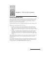
Chapter 1 The LS 4071 Scanner
Scanning Made Easy
The LS 4071 scanner lets you scan a bar code and transmit the data to a base
station up to 10 feet (3 meters) away, without a physical cable to limit your
movement. Instead, the scanner communicates with the base station
through a low power radio transmission.
The base station also serves as a charging station for the scanner’s battery pack.
There are two systems from which to choose.
• LS 4074 - An LS 4071 scanner and an RL474 base station. This system
allows you to communicate with an RS-232 host with a direct connect
cable, or to most other terminal types by using a Symbol Synapse™ Smart
Cable.
• LS 4075 - An LS 4071 scanner and an RL475 base station. This system is
compatible with the entire line of IBM 468X/469X terminals. Like the
RL474, this base station also accommodates the full line of Synapse Smart
Cables.
Additionally, there are different laser classes and transmission frequencies
for various global locations. Ask your Symbol representative for specific
information.
The LS 4071 successfully reads most code symbologies, densities, and colors,
produced by a wide range of printing techniques, and scans at the rate of 36
scans per second. See the LS 4071 Decode Zone on page 3-4.
1-1
LS 4071 Product Reference Guide
Rechargeable Battery Pack
In the handle of the scanner, there is a rechargeable NiCad battery pack. This
provides all power to the scanner during normal operation. It provides 250 mA
hours, which is sufficient for normal operation during a typical 12-hour shift.
When fully depleted, the battery pack can be recharged to full charge within 2
hours, with the LS 4071 inserted into the RL 47X base station. Alternatively,
the battery module can be recharged in the Universal Four-Slot Charger/
Recharger in approximately 1 1/2 hours.
1-2
The LS 4071 Scanner
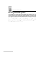
The Base Station
The base station receives scan data from the scanner via an RF transmission
and acknowledges receipt with an audible beep. It then transmits that data to
the host device through an attached cable. It also acts as a holder for the
scanner.
The base station serves as a charging stand capable of charging the scanner’s
battery pack (in the handle). The charging stand has a charge status indicator
light.
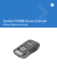
Figure 1-1. Scanner and Base Station
1-3
LS 4071 Product Reference Guide
1-4
Chapter 2 Set Up
Unpacking
Remove the scanner from its packing and inspect it for damage. If the scanner
was damaged in transit, call the Symbol Support Center at one of the telephone
numbers listed on page viii. KEEP THE PACKING. It is the approved shipping
container and should be used if you ever need to return your equipment for
servicing.
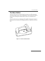
Setting Up the Base Station
1. Place the base station on a horizontal surface. Remember the scanner’s
operating range is approximately 10 feet (3 meters). It is preferable to have
the scanner and base station in line of sight. Placing the base station near
any large metal mass (e.g., a filing cabinet) may interfere with scanner/base
station communications. The base station may be placed on a shelf below a
counter. This placement, however, may also result in less than optimum
scanner/base station communications.
2. Connect an interface or adapter cable (for Synapse cables) to the base
station.
3. If using a direct connect interface cable, it should be connected to the
appropriate connector on the host. See Connecting to a Host on page 2-5.
Interface or
Adapter Cable
Power Cable
Figure 2-1. Host and Power Cables
2-1
LS 4071 Product Reference Guide
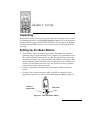
4. The Synapse adapter cables have a flying power lead. Connect this lead to
the receptacle in the Synapse cable, as shown below. See the Synapse guide
for details.
Synapse
Adapter Cable
Flying Power Lead
Figure 2-2. Synapse and Adapter Cable
5. Connect an appropriate power supply to the power receptacle on the base
station. You will hear three beeps and the indicator light on the base station
will blink, signifying successful power-up.
2-2
Set Up
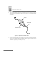
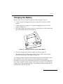
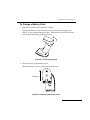
Charging the Battery
Before its first use, the LS 4071 batteries must be charged. To do so:
1. Connect the power supply to the power input jack on the RL 47X base
station.
2. Connect the power supply to a receptacle supplying AC power of the
proper voltage level.
3. Insert the scanner into the base station, so that the nose of the scanner and
tip of the handle seat into the receptacles.
Figure 2-3. Placing the Scanner into the Base Station
4. Check the charge status indicator light. See table on page 4-6.
5. The battery pack will fully charge within 2 hours. When fully charged,
proceed with pairing, as described on page 2-4.
As a charging stand, the base station recharges batteries in the scanner when
the scanner is in the cradle. The status of the scanner battery module
determines the charge rate. If the battery module is at or near full charge, the
base station supplies a trickle charge. If the battery module is at less than full
charge, there is a programmed charge. Note that the scanner can be removed
from the base station at any time.
2-3
LS 4071 Product Reference Guide
Battery Life
When batteries begin to run down, the scanner emits 4 high tone beeps. You
then have about 10 scans remaining. Although NiCad batteries are
rechargeable, they do have a limited life. In typical applications, the batteries
should last about two years. As they begin to age, batteries do not hold a charge
as long as when they were fresh; you have to charge them more often. New
battery packs can be obtained from Symbol Technologies. See your Symbol
representative for more information.
Pairing the Scanner with the Base Station
The wireless “connection” between the scanner and base is the low power
radio transmission through an RF transmitter in the scanner, and an RF receiver
in the base station. The actual communication consists of unidirectional
message packets from the scanner to the base. However, the scanner and base
station must be paired for this communication to work between the two
devices.
Each base station is assigned a unique address in the factory. To pair the
scanner with the base station:
• Scan the PAIRING bar code on the RL 47X base. The bar code is located
in the well in which the scanner head rests. An additional pairing bar
code can be found on the bottom of the base.
• Successful pairing is indicated by a warble beep from the scanner, then
the base. If either beep is not heard, the pairing was unsuccessful.
The scanner and base should be configured with the same set of parameters.
Scanning the bar code below ensures that the scanner’s parameters are sent to
the base.
2-4
Set Up
Connecting to a Host
With some terminal types, the LS 4071 is unable to answer host terminal polls
until the appropriate host type is selected. This may result in an error message
generated by the host. To correct this situation, select the proper parameter set
and initialize the host terminal. See Chapter 2 for more information.
RS-232C
Plug the cable from the RL 474 base station into the appropriate port on the host
device.
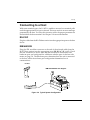
IBM 468X/9X
Plug the SDL modular connector at the end of the selected cable from the
RL 475 base station into the appropriate port (5B, 9B, 9C, 9E, or 17). Check
that the connection is secure. Note that the unit may be connected to one
hardware port, and configured for a different software port via the bar code
menus on page 5-8. The hardware ports determine how the unit is connected
to the host, while the software port configuration determines how it
communicates.
LS 4071
IBM 4683/84/93/94 Cash Register
Base
Figure 2-4. Typical System Configuration
2-5
LS 4071 Product Reference Guide
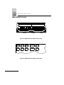
IBM 468X/9X (Contd)
PORT 5B
PORT 9B
PORT 17
Figure 2-5. IBM 4683 Rear Panel With Cover Removed
9B
5B
17
Figure 2-6. IBM 4684 Rear Panel With Cover Removed
2-6
Set Up
IBM 468X/9X (Contd)
5B
9C
9B
Figure 2-7. IBM 4693 Rear Panel With Cover Removed
PORT 9E
Figure 2-8. IBM 4694 Rear Panel With Cover Removed
Wand Emulation, OCIA, OCR, Keyboard Wedges
See the instructions packed with the appropriate Synapse cable. Adapter cable
required. See Figure 2-2.
2-7
LS 4071 Product Reference Guide
2-8
Chapter 3 Scanning
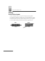
Ready, Test, Scan
1. Ready
Make sure connections are secure.
2. Test
Aim the scanner away from you and press the trigger. When you press
the trigger, the scanning beam is energized for approximately 3.0
seconds (default).
3. Scan
Make sure the symbol you want to scan is within the scanning range. See
the LS 4071 Decode Zone diagram on page 3-4.
The scanner has read the symbol when:
• The yellow LED on the rear of the scanner turns green for a short period
of time after the scanning beam turns off.
The data has been successfully sent to the base station when:
• You hear a short, high tone beep from the base (if default beeper settings
are selected).
• The yellow LED on the base blinks.
3-1
LS 4071 Product Reference Guide
Aiming
Scan the Entire Symbol
• Your scan beam must cross every bar and space on the symbol.
• The larger the symbol, the farther away you should hold the scanner.
• Hold the scanner closer for symbols with bars that are close together.
• A short, high tone beep from the base indicates a good decode.
3-2
RIGHT
WRONG
012345
012345
Scanning
Hold at an Angle
Do not hold the scanner directly over the bar code. Laser light reflecting directly
back into the scanner from the bar code is known as specular reflection. This
strong light can “blind” the scanner and make decoding difficult. The area
where specular reflection occurs is known as a “dead zone.”
You can tilt the scanner up to 65° forward or back and still achieve a successful
decode. Simple practice quickly shows what tolerances to work within.
Figure 3-1. Maximum Tilt Angles and Dead Zone
3-3
LS 4071 Product Reference Guide
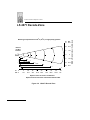
LS 4071 Decode Zone
In. Cm.
15 38.1
Nose of
LS 4071
Scanner
1
5 Mil
4.75
7.5 Mil
.5
9
80% UPC
100% UPC
0
0
11
16
20 Mil Minimum Element Width
1
In. 0
Cm. 0
35
55 Mil Minimum Element Width
3
5
12.7
10
25.4
15
38.1
20
50.8
25
63.5
30
76.2
45
35
88.9
40
101.6
45
114.
Depth of Field in Inches / Centimeters
Depth of field as a function of minimum element width.
Figure 3-2. LS 4071 Decode Zone
3-4
25.4
5
12.7
0
0
5
12.7
10
25.4
15
38.1
26
40 Mil Minimum Element
2
10
Width of Field in Inches / Centimeters
NOTE: Typical performance at 68o F ( 20o C) on high quality symbols.
Scanning
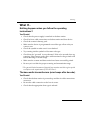
What If...
Nothing happens when you follow the operating
instructions?
You Should
• Check that the power supply is attached to the base station.
• Check for loose cable connections at the base station and host device.
• Check the scanner’s battery pack.
• Make sure the device is programmed to read the type of bar code you
want to scan.
• Check the symbol to make sure it is not defaced.
• Try scanning similar symbols of the same code type.
• Check that the “gas tank” is not exhausted.* Wait a few seconds, then try
scanning. If the scanner works, allow sufficient time for the gas tank to fill
before returning to normal usage.
• Make sure the scanner and base station have been successfully paired.
• Be sure you’re within the proper scanning and transmission range.
* The gas tank limits the amount of time the laser remains on within a given period
to conform to the requirements of IEC 825 Class 1.
The base emits transmit errors (error beeps after decode).
You Should
• Check that the base station is powered up and that its cable connections
are secure.
• Be sure the cable connection to the host is secure.
• Check that the appropriate host type is selected.
3-5
LS 4071 Product Reference Guide
What If...
The base emits no beeps.
You Should
• Check that you are within scanning transmit range.
• Check that the scanner is successfully paired with the base station.
• Be sure the base is powered-up.
Note: If after performing these checks the symbol still
does not scan, contact your distributor or call the
Symbol Support Center. See page viii for the
telephone number.
Programming the System
An LS 4071 is programmed by scanning sequences of bar codes; see Chapter 5.
3-6
Chapter 4 Maintenance and
Specifications
Maintenance
• Do not allow any abrasive material to touch the scanner window.
• Remove any dirt particles with a damp cloth.
• Wipe the scanner window using a damp cloth, and if necessary, a non-
ammonia based detergent.
• Do not spray water or other cleaning liquids directly into the scanner
window.
• If the contacts between the scanner and base become dirty, clean them
with either a pencil eraser or a cotton swab dampened with alcohol.
• Change the battery pack when the batteries no longer provide 12 hours of
scanning in typical usage. This should occur after 2 years or more,
depending on your daily use.
4-1
LS 4071 Product Reference Guide
Changing Battery Packs
Once a battery is fully charged, it will generally last up to 12 hours without
being returned to the base. By returning it to the base during the day, you
extend this time.
If you have a high volume environment and need fully charged batteries more
often, you can charge other battery packs on the Universal Four-Slot Battery
Charger. This way a charged battery pack is available when needed. In this
case, simply remove the depleted battery pack and replace it with a freshly
charged one.
User instructions are in the Universal Four-Slot Battery Charger Quick
Reference Guide.
Figure 4-1. Battery Pack
4-2
Maintenance and Specifications
To Change a Battery Pack:
1. Remove boot from lower handle of scanner.
Gently pull the boot from the back of the scanner. Avoid using sharp
objects, as they might damage the boot. Slide the back of the boot off the
scanner and remove by pushing forward.
Figure 4-2. Removing the Boot
2. Remove battery compartment cover.
Slide the battery cover toward the back of the unit.
To Remove
Figure 4-3. Removing the Battery Cover
4-3
LS 4071 Product Reference Guide
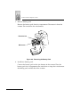
3. Remove battery pack.
Remove the battery pack from its compartment. Disconnect it from the
scanner. Do not remove the wire harness.
Disconnect here
Wire harness
Figure 4-4. Removing the Battery Pack
4. Install new battery pack.
Connect the battery pack to the wire harness in the scanner. Place the
battery pack in its compartment. Be careful not to crimp the wire between
the battery pack and the ribs of the scanner.
4-4
Maintenance and Specifications
5. Install battery pack cover.
Place the cover on the bottom of the scanner and gently push forward until
it engages (snaps into place).
To Replace
Figure 4-5. Replacing the Battery Cover
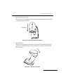
6. Re-install boot.
Slide boot onto the front of the base of the scanner. Be sure the charging
contacts are visible through the front of the boot. Gently stretch the boot
back into place.
Figure 4-6. Replacing the Boot
4-5
LS 4071 Product Reference Guide
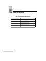
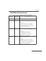
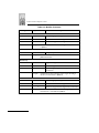
Charge Status LED Indications
On the base station, there is a yellow LED indicator which uses flashing
patterns to display the charger status, as shown in the table below.
Table 4-1. Charge Status LED Indications
Yellow LED
4-6
Status
Off
The scanner is not properly inserted or the battery
is not functioning properly.
Blinking Slowly
The scanner is properly seated in the base station
and trickle charging has begun.
Blinking Rapidly
The battery is actively fast charging. Charging will
be complete in less than 1 hour.
On
Battery charging is complete.
Maintenance and Specifications
Accessories
Required Accessories
LS 4071 scanners are sent as a package with required accessories, listed in the
Product Ordering Guide. Optional accessories are available at extra cost.
Optional Accessories
Optional accessories, listed in the Product Ordering Guide, include various
stands and holders, which are supplied at extra cost. Additional units of
standard accessories may also be purchased at extra cost.
4-7
LS 4071 Product Reference Guide
Technical Specifications
Table 4-2. Technical Specifications
Item
Description
Decode Capability
The LS 4071 can be programmed to decode the following
code types: UPC/EAN, Bookland EAN, Code 39, Code 39
Full ASCII, Trioptic Code 39, Code 93, Codabar, Interleaved
2 of 5, Code 128, EAN 128, Discrete 2 of 5, and MSI Plessey. Set
code length(s) for any linear code type. The LS 4071 can autodiscriminate between all of the above code types except for
Code 39 and Code 39 Full ASCII. Transmission of decoded
information depends on the capabilities of the attached
terminal.
Beeper Operation
(Base and Scanner)
User-selectable: Enabled, Disabled.
Scan Repetition Rate
36 (± 3) scans/sec (bidirectional)
Roll (Skew) Tolerance
± 25° from normal
Pitch
± 65° from normal
Yaw
± 60° from normal
Decode Depth of Field
See Decode Zone
Print Contrast Minimum
20% absolute dark/light differential, measured at the
wavelength of the laser diode.
Ambient Light Immunity
Artificial Lighting
Sunlight
4-8
200 ft. candles
8000 ft. candles
2153 lux
86112 lux
(@8 in. (20 cm) on low density bar codes)
Maintenance and Specifications
Table 4-2. (Continued)Technical Specifications
Item
Description
Operating Temperature
32° to 104°F
0° to 40°C
Storage Temperature
-40° to 140°F
-40° to 60°C
Humidity
5% to 95% (non-condensing)
Durability (Scanner)
4-ft. drop to concrete 1.2 m
Dimensions
See figure below
Laser Classifications
CDRH Class II
IEC Class 1
IEC 825 Class 2
Top
Side
8.9 in.
22.6 cm
5.3 in.
14.5 cm
8.9 in.
22.6 cm
3.5 in.
8.9 cm
Figure 4-7. Scanner/Base Approximate Dimensions
4-9
LS 4071 Product Reference Guide
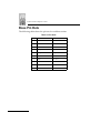
Base Pin Outs
The following table shows the pin outs for each base station.
Table 4-3. Pin Outs
Pin
4-10
RL474
RL475
1
Reserved
Reserved
2
Power Out
Power Out
3
Ground
Ground
4
Synapse Data
Synapse Data
5
Synapse Clock
Synapse Clock
6
RxD
Not used
7
TxD
Not used
8
DTR
Not used
9
CTS
B IBM
10
RTS
A IBM
Maintenance and Specifications
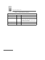
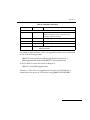
Beeper Indications
Table 4-4. Beeper Indications
Standard Use
Beeper Sequence
Emitted
From
Indication
Short high tone
Scanner &
Base
A bar code symbol was decoded (if decode beeper is
enabled).
4 Beeps - long low tone
Base
A transmission error has been detected in a scanned
symbol. The data is ignored. This occurs if a unit is
not properly configured. Check option settings.
5 Beeps - low tone
Base
Convert or format error.
Lo/hi/lo tone
Scanner
ADF transmit error.
Hi/hi/hi/lo tone
Base
RS-232 receive error.
4 Beeps - short hi
Scanner
Low battery.
3 Beeps - short hi
Base
Scanner/Base communications error. Rescan last
bar code.
Short high tone
Scanner
Correct entry scanned or correct menu sequence
performed.
Lo/hi tone
Scanner
Input error, incorrect bar code or “Cancel” scanned,
wrong entry, incorrect bar code programming
sequence; remain in program mode.
Hi/lo tone
Scanner
Keyboard parameter selected. Enter value using bar
code keypad.
Hi/lo/hi/lo tone
Scanner &
Base
Successful program exit with change in the
parameter setting.
Parameter Menu Scanning
4-11
LS 4071 Product Reference Guide
Table 4-4. (Continued) Beeper Indications
Code 39 Buffering
Hi/lo tone
Scanner
New Code 39 data was entered into the buffer.
3 Beeps - long high tone
Scanner
Code 39 buffer is full.
Lo/hi/lo tone
Scanner
The buffer was erased, or there was an attempt to
transmit an empty buffer. When the Code 39 buffer
was empty, the scanner read a command to clear or
to transmit a Code 39 buffer.
4 Beeps - long low tone
Scanner
Error in data transmission.
Lo/hi tone
Scanner
A successful transmission of buffered data.
4-12
Chapter 5 Parameter Menus
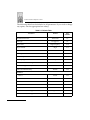
Operational Parameters
The LS 4071 is shipped with the default settings beginning on page 5-2. These
default values are stored in non-volatile memory and are preserved even when
the scanner is powered down. You can change these default values by scanning
the appropriate bar codes included in this manual. These new values replace
the standard default values in memory. The default parameter values can be
recalled by scanning the SET ALL DEFAULTS bar code on page 5-7.
Even if the default parameters suit your needs, you still must select a terminal
type. The base automatically identifies the host type on power-up. It makes this
determination provided the host is powered-up before the base is attached to
it. You must then select the appropriate terminal type for that host. For
example, if the base is connected to an IBM 4683, after you hear the power-up
beeps, you must then select the proper port. The same applies to all other host
types.
5-1
LS 4071 Product Reference Guide
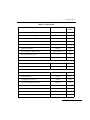
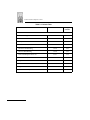
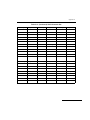
The following table lists the defaults for all parameters. If you wish to change
any option, scan the appropriate bar code(s).
Table 5-1. Default Table
Parameter
Default
Page
Number
Set Default Parameter
All Defaults
5-7
Host Type
See page 5-1
5-8
High Frequency
5-12
Beeper Volume
High
5-13
Laser On Time
3.0 seconds
5-14
Base Beep After Good Decode
Enable
5-15
Scanner Beep After Good Decode
Disable
5-16
Base Beep Type
Beep 1
5-17
Transmit “No Read” Message
Disable
5-18
1
5-19
Disable
5-22
UPC-A
Enable
5-23
UPC-E
Enable
5-23
EAN-8
Enable
5-24
EAN-13
Enable
5-24
Bookland EAN
Disable
5-25
Decode UPC/EAN Supplementals
Ignore
5-26
7
5-27
Beeper Tone
Linear Code Type Security Levels
Bi-directional Redundancy
UPC/EAN
Decode UPC/EAN Supplemental Redundancy
5-2
Parameter Menus
Table 5-1. Default Table
Parameter
Default
Page
Number
Transmit UPC-A Check Digit
Enable
5-28
Transmit UPC-E Check Digit
Enable
5-28
UPC-A Preamble
System Character
5-29
UPC-E Preamble
System Character
5-30
Convert UPC-E to A
Disable
5-31
EAN-8 Zero Extend
Disable
5-32
Type is EAN-13
5-33
UPC/EAN Security Levels
0
5-34
UPC/EAN Coupon Code
Disable
5-36
Code 128
Enable
5-37
UCC/EAN-128
Disable
5-38
Code 39
Enable
5-40
Trioptic Code 39
Disable
5-41
Set Length(s) for Code 39
2 to 55
5-43
Code 39 Check Digit Verification
Disable
5-44
Transmit Code 39 Check Digit
Disable
5-45
Code 39 Full ASCII Conversion
Disable
5-46
Buffer Code 39
Disable
5-47
Convert Code 39 to Code 32
Disable
5-50
Convert EAN-8 to EAN-13 Type
Code 128
Code 39
5-3
LS 4071 Product Reference Guide
Table 5-1. Default Table
Parameter
Default
Page
Number
Disable
5-51
4-55
5-52
Enable
5-54
14
5-55
I 2 of 5 Check Digit Verification
Disable
5-57
Transmit I 2 of 5 Check Digit
Disable
5-58
Convert I 2 of 5 to EAN 13
Disable
5-59
Disable
5-60
12
5-61
Disable
5-63
5-55
5-65
CLSI Editing
Disable
5-66
NOTIS Editing
Disable
5-67
Code 93
Code 93
Set Length(s) for Code 93
Interleaved 2 of 5
Interleaved 2 of 5
Set Length(s) for I 2 of 5
Discrete 2 of 5
Discrete 2 of 5
Set Length(s) for D 2 of 5
Codabar
Codabar
Set Lengths for Codabar
5-4
Parameter Menus
Table 5-1. Default Table
Parameter
Default
Page
Number
Disable
5-68
Any Length
5-70
One
5-71
Disable
5-72
Mod 10/Mod 10
5-73
None
5-75
0
5-76
7013
(<CR/LF> for serial)
5-77
Data as is
5-78
ASCII Data
5-80
MSI Plessey
MSI Plessey
Set Length(s) for MSI Plessey
MSI Plessey Check Digits
Transmit MSI Plessey Check Digit
MSI Plessey Check Digit Algorithm
Data Options
Transmit Code ID Character
Pause Duration
Prefix/Suffix Values
Scan Data Transmission Format
Transmit ASCII/Intermediate Data
5-5
LS 4071 Product Reference Guide
Table 5-1. Default Table
Parameter
Default
Page
Number
Standard
5-11
Baud Rate
9600
5-82
Parity
None
5-83
Disable
5-85
Hardware Handshaking
None
5-87
Software Handshaking
None
5-89
Host Serial Response Time-out
2 Sec.
5-92
RTS Line State
Low
5-93
Stop Bit Select
1
5-94
ASCII Format
8-Bit
5-95
Disable
5-96
0
5-97
RS-232C
RS-232 Host Type
Check Receive Errors
Beep on <BEL>
Intercharacter Delay
5-6
Parameter Menus
Set Default Parameter
Scanning this bar code returns all parameters to the values listed in the default
table beginning on page 5-2.
SET ALL DEFAULTS
5-7
LS 4071 Product Reference Guide
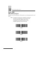
Host Type
IBM 46XX Host Types
To select one of the following as a POS Interface, scan the appropriate bar code
below.
Note: To properly communicate with 468X/9X terminals,
the driver corresponding to the port being used
must be loaded and enabled when you are
configuring your terminal system. See your
terminal’s operating manual for details.
Port 5B
Port 9B
Port 17
5-8
Parameter Menus
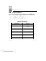
Host Type
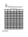
RS-232C Host Types
Three RS-232C hosts are set up with their own parameter default settings.
Selecting the ICL, Fujitsu or Nixdorf RS-232C terminal sets the defaults listed
below. These defaults take precedence over Standard RS-232 defaults. So, if
you’ve selected Fujitsu RS-232C, then select the Standard RS-232 defaults,
the Fujitsu defaults still take precedence. To return to the factory set
defaults, scan the SET ALL DEFAULTS bar code on page 5-7.
Table 5-2. Terminal Specific RS-232C
Parameter
Standard
ICL
FUJITSU
NIXDORF
Mode A/
Mode B
Transmit Code ID
No
Yes
Yes
Yes
Data Transmission Format
Data as is
Data/Suffix
Data/Suffix
Data/Suffix
Suffix
CR/LF
CR
CR
CR
Baud Rate
9600
9600
9600
9600
Parity
None
Even
None
Odd
Hardware Handshaking
None
RTS/CTS
Option 3
None
RTS/CTS
Option 3
Software Handshaking
None
None
None
None
Serial Response Time-out
2 Sec.
9.9 Sec.
2 Sec.
9.9 Sec.
Stop Bit Select
One
One
One
One
ASCII Format
8-Bit
8-Bit
8-Bit
8-Bit
Beep On <BEL>
Disabled
Disabled
Disabled
Disabled
RTS Line State
Low
High
Low
*Low = No
data to send
*In the Nixdorf Mode B, if CTS is Low, transmission of scan data is disabled. When CTS is High,
bar code data is transmitted to the host.
5-9
LS 4071 Product Reference Guide
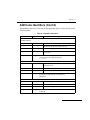
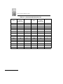
Host Type
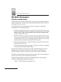
RS-232C Host Types
Selecting the ICL, Fujitsu, or Nixdorf RS-232C terminal enables the
transmission of Code ID Characters as listed below. These Code ID Characters
are not programmable and are separate from the Transmit Code ID feature. The
Transmit Code ID feature should not be enabled for these terminals.
Table 5-3. Terminal Specific Code ID Characters
ICL
5-10
FUJITSU
NIXDORF
UPC-A
“A”
“A”
“A”
UPC-E
“E”
“E”
“C0”
EAN-8
“FF”
“FF”
“B”
EAN-13
“F”
“F”
“A”
Code 39
“C” <len>
None
“M”
Codabar
“N” <len>
None
“N”
Code 128
“L” <len>
None
“K”
I 2 of 5
“I” <len>
None
“I”
Code 93
None
None
“L”
D 2 of 5
“H” <len>
None
“H”
UCC/EAN 128
“L” <len>
None
“P”
MSI/Plessey
None
None
“O”
Bookland EAN
“F”
“F”
“A”
Trioptic
None
None
None
Parameter Menus
Host Type
RS-232C Host Types
To select an RS-232C Host Interface, scan one of the following bar codes.
STANDARD RS-232C
ICL RS-232C
NIXDORF RS-232C Mode A
NIXDORF RS-232C Mode B
FUJITSU RS-232C
5-11
LS 4071 Product Reference Guide
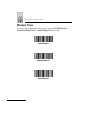
Beeper Tone
To select a decode beep frequency (tone), scan the LOW FREQUENCY,
MEDIUM FREQUENCY, or HIGH FREQUENCY bar code.
LOW FREQUENCY
MEDIUM FREQUENCY
HIGH FREQUENCY
5-12
Parameter Menus
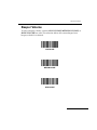
Beeper Volume
To select a beeper volume, scan the LOW VOLUME, MEDIUM VOLUME, or
HIGH VOLUME bar code. This selection affects the scanner beeper, base
beeper, or both if so selected.
LOW VOLUME
MEDIUM VOLUME
HIGH VOLUME
5-13
LS 4071 Product Reference Guide
Laser On Time
This parameter sets the maximum time decode processing continues during a
scan attempt. It is programmable in 0.1 second increments from 0.5 to 9.9
seconds.
To set a Laser On Time, scan the bar code below. Next scan two numeric bar
codes beginning on page 5-98 that correspond to the desired time on. Time less
than 1.0 second 1414must have a leading zero. For example, to set a Time On of
.5 seconds, scan the bar code below, then scan the “0” and “5” bar codes. If
you make an error, or wish to change your selection, scan CANCEL on page
5-100
LASER ON TIME
5-14
Parameter Menus
Base Beep After Good Decode
Scan this symbol if you want the base unit to beep after a good decode.
BASE BEEP AFTER GOOD DECODE
Do Not Beep After Good Decode
Scan this symbol if you do not want the base unit to beep after a good decode.
The beeper still operates during parameter menu scanning and indicates error
conditions.
DO NOT BEEP AFTER GOOD DECODE
5-15
LS 4071 Product Reference Guide
Scanner Beep After Good Decode
Scan this symbol if you want the scanner to beep after a good decode.
SCANNER BEEP AFTER GOOD DECODE
Do Not Beep After Good Decode
Scan this symbol if you want the scanner not to beep after a good decode. The
beeper still operates during parameter menu scanning and indicates error
conditions.
DO NOT BEEP AFTER GOOD DECODE
5-16
Parameter Menus
Base Beep Type
Select the type of beep for the base unit. This parameter is useful when two or
more systems are installed in proximity to each other. Unique beep patterns can
be set up to distinguish each system’s receipt of bar code data.
Beep 1
Beep 2
Beep 3
Beep 4
Beep 5
5-17
LS 4071 Product Reference Guide
Transmit “No Read” Message
When enabled, if a symbol does not decode, “NR” is transmitted. Any prefixes
or suffixes which have been enabled are appended around this message.
ENABLE NO READ
Do Not Transmit “No Read” Message
When disabled, if a symbol does not read, nothing is sent to the host.
DISABLE NO READ
5-18
Parameter Menus
Linear Code Type Security Level
(Does not apply to Code 128)
The LS 4071 offers four levels of decode security for linear code types (e.g. Code
39, Interleaved 2 of 5). Higher security levels are selected for decreasing levels
of bar code quality. As security levels increase, the scanner’s aggressiveness
decreases.
Select the security level appropriate for your bar code quality.
Linear Security Level 1
The following code types must be successfully read twice before being
decoded:
Code Type
Length
Codabar
All
MSI Plessey
4 or less
D 2 of 5
8 or less
I 2 of 5
8 or less
LINEAR SECURITY LEVEL 1
5-19
LS 4071 Product Reference Guide
Linear Code Type Security Level (Cont’d)
Linear Security Level 2
The following code types must be successfully read twice before being
decoded:
Code Type
All
Length
All
LINEAR SECURITY LEVEL 2
Linear Security Level 3
Code types other than the following must be successfully read twice before
being decoded. The following codes must be read three times:
Code Type
Length
MSI Plessey
4 or less
D 2 of 5
8 or less
I 2 of 5
8 or less
LINEAR SECURITY LEVEL 3
5-20
Parameter Menus
Linear Code Type Security Level (Cont’d)
Linear Security Level 4
The following code types must be successfully read three times before being
decoded:
Code Type
All
Length
All
LINEAR SECURITY LEVEL 4
5-21
LS 4071 Product Reference Guide
Bi-directional Redundancy
This parameter is only valid when a Linear Code Type Security Level (see
page 5-19) is enabled. When this parameter is enabled, a bar code must be
successfully scanned in both directions (forward and reverse) before being
decoded.
ENABLE BI-DIRECTIONAL REDUNDANCY
DISABLE BI-DIRECTIONAL REDUNDANCY
5-22
Parameter Menus
Enable/Disable UPC-E/UPC-A
To enable or disable UPC-E or UPC-A, scan the appropriate bar code below.
ENABLE UPC-E
DISABLE UPC-E
ENABLE UPC-A
DISABLE UPC-A
5-23
LS 4071 Product Reference Guide
Enable/Disable EAN-8/EAN-13
To enable or disable EAN-8 or EAN-13, scan the appropriate bar code below.
ENABLE EAN-8
DISABLE EAN-8
ENABLE EAN-13
DISABLE EAN-13
5-24
Parameter Menus
Enable/Disable Bookland EAN
To enable or disable EAN Bookland, scan the appropriate bar code below.
ENABLE BOOKLAND EAN
DISABLE BOOKLAND EAN
5-25
LS 4071 Product Reference Guide
Decode UPC/EAN Supplementals
Supplementals are additionally appended characters (2 or 5) according to
specific code format conventions (e.g., UPC A+2, UPC E+2, EAN 8+2). Three
options are available.
• If UPC/EAN with supplemental characters is selected, UPC/EAN
symbols without supplemental characters are not decoded.
• If UPC/EAN without supplemental characters is selected, and the
LS 4071 is presented with a UPC/EAN plus supplemental symbol, the
UPC/EAN is decoded and the supplemental characters ignored.
• An autodiscriminate option is also available. If this option is selected,
choose an appropriate Decode UPC/EAN Supplemental Redundancy
value from the next page. A value of 5 or more is recommended.
Note: To minimize the risk of invalid data transmission,
select whether to read or ignore supplemental
characters.
DECODE UPC/EAN WITH SUPPLEMENTALS
IGNORE UPC/EAN WITH SUPPLEMENTALS
AUTODISCRIMINATE UPC/EAN SUPPLEMENTALS
5-26
Parameter Menus
Decode UPC/EAN Supplemental Redundancy
With Autodiscriminate UPC/EAN Supplementals selected, this option adjusts
the number of times a symbol without supplementals is decoded before
transmission. The range is from two to 20 times. Five or above is recommended
when decoding a mix of UPC/EAN symbols with and without supplementals,
and the autodiscriminate option is selected.
Scan the bar code below to select a decode redundancy value. Next scan two
numeric bar codes beginning on page 5-98. Single digit numbers must have a
leading zero. If you make an error, or wish to change your selection, scan
CANCEL on page 5-100.
DECODE UPC/EAN
SUPPLEMENTAL REDUNDANCY
5-27
LS 4071 Product Reference Guide
Transmit UPC-A/UPC-E Check Digit
Scan the appropriate bar code below to transmit the symbol with or without
the UPC-A or UPC-E check digit.
TRANSMIT UPC-A CHECK DIGIT
DO NOT TRANSMIT UPC-A CHECK DIGIT
TRANSMIT UPC-E CHECK DIGIT
DO NOT TRANSMIT UPC-E CHECK DIGIT
5-28
Parameter Menus
UPC-A Preamble
Three options are given for lead-in characters for UPC-A symbols transmitted
to the host device: transmit system character only, transmit system character
and country code (“0” for USA), and no preamble transmitted. The lead-in
characters are considered part of the symbol.
NO PREAMBLE
(<DATA>)
SYSTEM CHARACTER
(<SYSTEM CHARACTER> <DATA>)
SYSTEM CHARACTER & COUNTRY CODE
(< COUNTRY CODE> <SYSTEM CHARACTER> <DATA>)
5-29
LS 4071 Product Reference Guide
UPC-E Preamble
Three options are given for lead-in characters for UPC-E symbols transmitted
to the host device: transmit system character only, transmit system character
and country code (“0” for USA), and no preamble transmitted. The lead-in
characters are considered part of the symbol.
NO PREAMBLE
(<DATA>)
SYSTEM CHARACTER
(<SYSTEM CHARACTER> <DATA>)
SYSTEM CHARACTER & COUNTRY CODE
(< COUNTRY CODE> <SYSTEM CHARACTER> <DATA>)
5-30
Parameter Menus
Convert UPC-E to UPC-A
This parameter converts UPC-E (zero suppressed) decoded data to UPC-A
format before transmission. After conversion, data will follow UPC-A format
and be affected by UPC-A programming selections (e.g., Preamble, Check
Digit).
Scanning DO NOT CONVERT UPC-E TO UPC-A allows you to transmit
UPC-E (zero suppressed) decoded data.
CONVERT UPC-E TO UPC-A
(ENABLE)
DO NOT CONVERT UPC-E TO UPC-A
(DISABLE)
5-31
LS 4071 Product Reference Guide
EAN Zero Extend
If this parameter is enabled, five leading zeros are added to decoded EAN-8
symbols to make them compatible in format to EAN-13 symbols.
Disabling this parameter returns EAN-8 symbols to their normal format.
ENABLE EAN ZERO EXTEND
DISABLE EAN ZERO EXTEND
5-32
Parameter Menus
Convert EAN-8 to EAN-13 Type
When EAN Zero Extend is enabled, this parameter gives you the option of
labeling the extended symbol as either an EAN-13 bar code, or an EAN-8 bar
code.
When EAN Zero Extend is disabled, this parameter has no effect on bar code
data.
TYPE IS EAN-13
TYPE IS EAN-8
5-33
LS 4071 Product Reference Guide
UPC/EAN Security Level
The LS 4071 offers four levels of decode security for UPC/EAN bar codes.
Increasing levels of security are provided for decreasing levels of bar code
quality. There is an inverse relationship between security and scanner
aggressiveness, so be sure to choose only that level of security necessary for
any given application.
UPC/EAN Security Level 0
This is the default setting which allows the scanner to operate in its most
aggressive state, while providing sufficient security in decoding “in-spec”
UPC/EAN bar codes.
UPC/EAN SECURITY LEVEL 0
UPC/EAN Security Level 1
As bar code quality levels diminish, certain characters become prone to misdecodes before others (i.e., 1, 2, 7, 8). If you are experiencing mis-decodes of
poorly printed bar codes, and the mis-decodes are limited to these characters,
select this security level.
UPC/EAN SECURITY LEVEL 1
5-34
Parameter Menus
UPC/EAN Security Level (Cont’d)
UPC/EAN Security Level 2
If you are experiencing mis-decodes of poorly printed bar codes, and the misdecodes are not limited to characters 1, 2, 7, and 8, select this security level.
UPC/EAN SECURITY LEVEL 2
UPC/EAN Security Level 3
If you have tried Security Level 2, and are still experiencing misdecodes, select
this security level. Be advised that selecting this option is an extreme measure
against mis-decoding severely out of spec bar codes. Selection of this level of
security significantly impairs the decoding ability of the scanner. If this level of
security is necessary, you should try to improve the quality of your bar codes.
UPC/EAN SECURITY LEVEL 3
5-35
LS 4071 Product Reference Guide
UPC/EAN Coupon Code
When enabled, this parameter will decode UPC-A, UPC-A with 2
supplemental characters, UPC-A with 5 supplemental characters, and UPC-A/
EAN128 bar codes. UPC-A with supplemental characters need not be enabled.
ENABLE UPC/EAN COUPON CODE
DISABLE UPC/EAN COUPON CODE
5-36
Parameter Menus
Enable/Disable Code 128
To enable or disable Code 128, scan the appropriate bar code below.
ENABLE CODE 128
DISABLE CODE 128
5-37
LS 4071 Product Reference Guide
Enable/Disable UCC/EAN-128
To enable or disable UCC/EAN-128, scan the appropriate bar code below. (See
Appendix A for details on UCC/EAN-128.)
ENABLE UCC/EAN-128
DISABLE UCC/EAN-128
5-38
Parameter Menus
Lengths for Code 128
No length setting is required for Code 128. The default setting is Any Length.
5-39
LS 4071 Product Reference Guide
Enable/Disable Code 39
To enable or disable Code 39, scan the appropriate bar code below.
ENABLE CODE 39
DISABLE CODE 39
5-40
Parameter Menus
Enable/Disable Trioptic Code 39
Trioptic Code 39 symbols always contain six characters. Trioptic Code 39 and
Code 39 Full ASCII cannot be enabled simultaneously. If you get an error beep
when enabling Trioptic Code 39, disable Code 39 Full ASCII and try again. To
enable or disable Trioptic Code 39, scan the appropriate bar code below.
ENABLE TRIOPTIC CODE 39
DISABLE TRIOPTIC CODE 39
5-41
LS 4071 Product Reference Guide
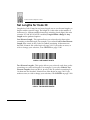
Set Lengths for Code 39
Lengths for Code 39 may be set for any length, one or two discrete lengths, or
lengths within a specific range. The length of a code refers to the number of
characters (i.e., human readable characters), including check digit(s) the code
contains. If Code 39 Full ASCII is enabled, Length Within a Range or Any
Length are the preferred options.
One Discrete Length - This option allows you to decode only those codes
containing a selected length. For example, if you select Code 39 One Discrete
Length, then scan 1, 4, only Code 39 symbols containing 14 characters are
decoded. Numeric bar codes begin on page 5-98. If you make an error, or
wish to change your selection, scan CANCEL on page 5-100.
CODE 39 - ONE DISCRETE LENGTH
Two Discrete Lengths - This option allows you to decode only those codes
containing two selected lengths. For example, if you select Code 39 Two
Discrete Lengths, then scan 0, 2, 1, 4, only Code 39 symbols containing 2 or
14 characters are decoded. Numeric bar codes begin on page 5-98. If you
make an error, or wish to change your selection, scan CANCEL on page 5-100.
CODE 39 - TWO DISCRETE LENGTHS
5-42
Parameter Menus
Set Lengths for Code 39 (Cont’d)
Length Within Range - This option allows you to decode a code type
within a specified range. For example to decode Code 39 symbols
containing between 4 and 12 characters, first scan Code 39 Length Within
Range. Then scan 0, 4, 1 and 2 (single digit numbers must always be preceded
by a leading zero). Numeric bar codes begin on page 5-98. If you make an
error, or wish to change your selection, scan CANCEL on page 5-100.
CODE 39 - LENGTH WITHIN RANGE
Any Length - Scanning this option allows you to decode Code 39 symbols
containing any number of characters.
CODE 39 - ANY LENGTH
5-43
LS 4071 Product Reference Guide
Code 39 Check Digit Verification
When enabled, this parameter checks the integrity of a Code 39 symbol to
ensure it complies with specified algorithms.
Only those code 39 symbols which include a modulo 43 check digit are
decoded when this parameter is enabled.
ENABLE CODE 39 CHECK DIGIT
DISABLE CODE 39 CHECK DIGIT
5-44
Parameter Menus
Transmit Code 39 Check Digit
Scan this symbol if you want to transmit the check digit with the data.
TRANSMIT CODE 39 CHECK DIGIT
(ENABLE)
Do Not Transmit Code 39 Check Digit
Scan this symbol if you want to transmit the data without the check digit.
DO NOT TRANSMIT CODE 39 CHECK DIGIT
(DISABLE)
5-45
LS 4071 Product Reference Guide
Enable/Disable Code 39 Full ASCII
To enable or disable Code 39 Full ASCII, scan the appropriate bar code below.
When enabled, the ASCII character set assigns a code to letters, punctuation
marks, numerals, and most control keystrokes on the keyboard.
The first 32 codes are non-printable and are assigned to keyboard control
characters such as BACKSPACE and RETURN. The other 96 are called
printable codes because all but SPACE and DELETE produce visible characters.
Code 39 Full ASCII interprets the bar code special character ($ + % /) preceding
a Code 39 character and assigns an ASCII character value to the pair. For
example, when Code 39 Full ASCII is enabled and a +B is scanned, it is
interpreted as b, %J as ?, and $H emulates the keystroke BACKSPACE.
Scanning ABC$M will output the keystroke equivalent of ABC ENTER. Refer
to the ASCII table in Appendix A.
Code 39 Full ASCII and Trioptic Code 39 cannot be enabled simultaneously. If
you get an error beep when enabling Code 39 Full ASCII, disable Trioptic Code
39 and try again.
The scanner does not autodiscriminate between Code 39 and Code 39 Full
ASCII.
ENABLE CODE 39 FULL ASCII
DISABLE CODE 39 FULL ASCII
5-46
Parameter Menus
Code 39 Buffering (Scan & Store)
When you select the scan and store option, all Code 39 symbols having a
leading space as a first character are temporarily buffered in the unit to be
transmitted later. The leading space is not buffered.
Decode of a valid Code 39 symbol with no leading space causes transmission
in sequence of all buffered data in a first-in first-out format, plus transmission
of the “triggering” symbol. See the following pages for further details.
When the scan and transmit option is selected, decoded Code 39 symbols
without leading spaces are transmitted without being stored in the buffer.
Scan and Store affects Code 39 decodes only. If you select scan and store, it is
recommended that you configure the scanner to decode Code 39 symbology
only.
BUFFER CODE 39
(ENABLE)
DO NOT BUFFER CODE 39
(DISABLE)
5-47
LS 4071 Product Reference Guide
Code 39 Buffering (Scan & Store)
While there is data in the transmission buffer, deleting Code 39 buffering
capability via the parameter menu is not allowed. The buffer holds 200 bytes of
information.
To allow disabling of Code 39 buffering, first force the buffer transmission
(see Transmit Buffer) or clear the buffer. Both the CLEAR BUFFER and
TRANSMIT BUFFER bar codes are length 1. Be sure Code 39 length is set to
include length 1.
Buffer Data
To buffer data, Code 39 buffering must be enabled, and a symbol must be read
with a space immediately following the start pattern.
• Unless symbol overflows the transmission buffer, the unit gives lo/hi
beep to indicate successful decode and buffering. See Overfilling
Transmission Buffer.
• Unit adds the message, excluding the leading space to the transmission
buffer.
• No transmission occurs.
Clear Transmission Buffer
To clear the transmission buffer, read a symbol which contains only a start
character, a dash (minus), and a stop character.
• Unit issues a short hi/lo/hi beep to signal that the transmission buffer has
been erased, and no transmission has occurred.
• Unit erases the transmission buffer.
• No transmission occurs.
CLEAR BUFFER
5-48
Parameter Menus
Code 39 Buffering (Scan & Store)
Transmit Buffer
To transmit the buffer, read a symbol containing either the first or second
condition:
1. Only a start character, a plus (+), and a stop character.
• The unit signals that the transmission buffer has been sent (a lo/hi beep).
• Unit sends the buffer.
• Unit clears the buffer.
TRANSMIT BUFFER
2. A Code 39 bar code with leading character other than a space.
• The unit signals a good decode and buffering of that decode has occurred
by giving a hi/lo beep.
• Unit transmits the buffer.
• Unit signals that the buffer has been transmitted with a lo/hi beep.
Overfilling Transmission Buffer
If the symbol just read will result in an overflow of the transmission buffer:
• Unit indicates that the symbol has been rejected by issuing three long,
high beeps.
• No transmission occurs. Data in buffer is not affected.
Attempt to Transmit an Empty Buffer
If the symbol just read was the transmit buffer symbol and the Code 39 buffer
is empty:
• A short lo/hi/lo beep signals that the buffer is empty.
• No transmission occurs.
• The buffer remains empty.
5-49
LS 4071 Product Reference Guide
Convert Code 39 to Code 32
Scan this symbol if you want to convert Code 39 to Code 32.
CONVERT CODE 39 TO CODE 32
(ENABLE)
Note: Code 39 must be enabled in order for this
parameter to function.
Do Not Convert Code 39 to Code 32
Scan this symbol if you do not want to convert Code 39 to Code 32.
DO NOT CONVERT CODE 39 TO CODE 32
(DISABLE)
5-50
Parameter Menus
Enable/Disable Code 93
To enable or disable Code 93, scan the appropriate bar code below.
ENABLE CODE 93
DISABLE CODE 93
5-51
LS 4071 Product Reference Guide
Set Lengths for Code 93
Lengths for Code 93 may be set for any length, one or two discrete lengths, or
lengths within a specific range. The length of a code refers to the number of
characters (i.e., human readable characters), including check digit(s) the code
contains.
One Discrete Length - This option allows you to decode only those codes
containing a selected length. For example, if you select Code 93 One Discrete
Length, then scan 1, 4, only Code 93 symbols containing 14 characters are
decoded. Numeric bar codes begin on page 5-98. If you make an error, or
wish to change your selection, scan CANCEL on page 5-100.
CODE 93 - ONE DISCRETE LENGTH
Two Discrete Lengths - This option allows you to decode only those codes
containing two selected lengths. For example, if you select Code 93 Two
Discrete Lengths, then scan 0, 2, 1, 4, only Code 93 symbols containing 2 or
14 characters are decoded. Numeric bar codes begin on page 5-98. If you
make an error, or wish to change your selection, scan CANCEL on page 5-100.
CODE 93 - TWO DISCRETE LENGTHS
5-52
Parameter Menus
Set Lengths for Code 93 (Cont’d)
Length Within Range - This option allows you to decode a code type
within a specified range. For example to decode Code 93 symbols
containing between 4 and 12 characters, first scan Code 93 Length Within
Range. Then scan 0, 4, 1 and 2 (single digit numbers must always be preceded
by a leading zero). Numeric bar codes begin on page 5-98. If you make an
error, or wish to change your selection, scan CANCEL on page 5-100.
CODE 93 - LENGTH WITHIN RANGE
Any Length - Scanning this option allows you to decode Code 93 symbols
containing any number of characters.
CODE 93 - ANY LENGTH
5-53
LS 4071 Product Reference Guide
Enable/Disable Interleaved 2 of 5
To enable or disable Interleaved 2 of 5, scan the appropriate bar code below.
ENABLE INTERLEAVED 2 OF 5
DISABLE INTERLEAVED 2 OF 5
5-54
Parameter Menus
Set Lengths for Interleaved 2 of 5
Lengths for I 2 of 5 may be set for any length, one or two discrete lengths, or
lengths within a specific range. The length of a code refers to the number of
characters (i.e., human readable characters) the code contains and includes
check digits.
One Discrete Length - This option allows you to decode only those codes
containing a selected length. For example, if you select I 2 of 5 One Discrete
Length, then scan 1, 4, the only I 2 of 5 symbols decoded are those containing
14 characters. Numeric bar codes begin on page 5-98. If you make an error,
or wish to change your selection, scan CANCEL on page 5-100.
I 2 of 5 - ONE DISCRETE LENGTH
Two Discrete Lengths - This option allows you to decode only those codes
containing two selected lengths. For example, if you select I 2 of 5 Two Discrete
Lengths, then scan 0, 2, 1, 4, the only I 2 of 5 symbols decoded are those
containing 2 or 14 characters. Numeric bar codes begin on page 5-98. If you
make an error, or wish to change your selection, scan CANCEL on page 5100.
I 2 of 5 - TWO DISCRETE LENGTHS
5-55
LS 4071 Product Reference Guide
Set Lengths for Interleaved 2 of 5 (Cont’d)
Length Within Range - This option allows you to decode a code type within
a specified range. For example to decode I 2 of 5 symbols containing between
4 and 12 characters, first scan I 2 of 5 Length Within Range. Then scan 0, 4, 1
and 2 (single digit numbers must always be preceded by a leading zero).
Numeric bar codes begin on page 5-98. If you make an error, or wish to
change your selection, scan CANCEL on page 5-100.
I 2 of 5 - LENGTH WITHIN RANGE
Any Length - Scanning this option allows you to decode I 2 of 5 symbols
containing any number of characters.
Note: Selecting this option may lead to misdecodes for
I 2 of 5 codes.
I 2 of 5 - ANY LENGTH
5-56
Parameter Menus
I 2 of 5 Check Digit Verification
When enabled, this parameter checks the integrity of an I 2 of 5 symbol to
ensure it complies a specified algorithm, either USS (Uniform Symbology
Specification), or OPCC (Optical Product Code Council).
DISABLE
USS CHECK DIGIT
OPCC CHECK DIGIT
5-57
LS 4071 Product Reference Guide
Transmit I 2 of 5 Check Digit
Scan this symbol if you want to transmit the check digit with the data.
TRANSMIT I 2 of 5 CHECK DIGIT
(ENABLE)
Do Not Transmit I 2 of 5 Check Digit
Scan this symbol if you want to transmit the data without the check digit.
DO NOT TRANSMIT I 2 of 5 CHECK DIGIT
(DISABLE)
5-58
Parameter Menus
Convert I 2 of 5 to EAN-13
This parameter converts a 14 character I 2 of 5 code into EAN-13, and transmits
to the host as EAN-13. In order to accomplish this, the I 2 of 5 code must be
enabled, one length must be set to 14, and the code must have a leading zero
and a valid EAN-13 check digit.
CONVERT I 2 of 5 to EAN-13
(ENABLE)
DO NOT CONVERT I 2 of 5 to EAN-13
(DISABLE)
5-59
LS 4071 Product Reference Guide
Enable/Disable Discrete 2 of 5
To enable or disable Discrete 2 of 5, scan the appropriate bar code below.
ENABLE DISCRETE 2 OF 5
DISABLE DISCRETE 2 OF 5
5-60
Parameter Menus
Set Lengths for Discrete 2 of 5
Lengths for D 2 of 5 may be set for any length, one or two discrete lengths, or
lengths within a specific range. The length of a code refers to the number of
characters (i.e., human readable characters) the code contains, and includes
check digits.
One Discrete Length - This option allows you to decode only those codes
containing a selected length. For example, if you select D 2 of 5 One Discrete
Length, then scan 1, 4, the only D 2 of 5 symbols decoded are those containing
14 characters. Numeric bar codes begin on page 5-98. If you make an error,
or wish to change your selection, scan CANCEL on page 5-100.
D 2 of 5 - ONE DISCRETE LENGTH
Two Discrete Lengths - This option allows you to decode only those codes
containing two selected lengths. For example, if you select D 2 of 5 Two
Discrete Lengths, then scan 0, 2, 1, 4, the only D 2 of 5 symbols decoded are
those containing 2 or 14 characters. Numeric bar codes begin on page 5-98.
If you make an error, or wish to change your selection, scan CANCEL on
page 5-100.
D 2 of 5 - TWO DISCRETE LENGTHS
5-61
LS 4071 Product Reference Guide
Set Lengths for Discrete 2 of 5 (Cont’d)
Length Within Range - This option allows you to decode a code type
within a specified range. For example to decode D 2 of 5 symbols containing
between 4 and 12 characters, first scan D 2 of 5 Length Within Range. Then
scan 0, 4, 1 and 2 (single digit numbers must always be preceded by a leading
zero). Numeric bar codes begin on page 5-98. If you make an error, or wish to
change your selection, scan CANCEL on page 5-100.
D 2 of 5 - LENGTH WITHIN RANGE
Any Length - Scanning this option allows you to decode D 2 of 5 symbols
containing any number of characters.
Note: Selecting this option may lead to misdecodes for
D 2 of 5 codes.
D 2 of 5 - ANY LENGTH
5-62
Parameter Menus
Enable/Disable Codabar
To enable or disable Codabar, scan the appropriate bar code below.
ENABLE CODABAR
DISABLE CODABAR
5-63
LS 4071 Product Reference Guide
Set Lengths for Codabar
Lengths for Codabar may be set for any length, one or two discrete lengths, or
lengths within a specific range. The length of a code refers to the number of
characters (i.e., human readable characters) the code contains. It also includes
any start or stop characters.
One Discrete Length - This option allows you to decode only those codes
containing a selected length. For example, if you select Codabar One Discrete
Length, then scan 1, 4, the only Codabar symbols decoded are those containing
14 characters. Numeric bar codes begin on page 5-98. If you make an error,
or wish to change your selection, scan CANCEL on page 5-100.
CODABAR - ONE DISCRETE LENGTH
Two Discrete Lengths - This option allows you to decode only those codes
containing two selected lengths. For example, if you select Codabar Two
Discrete Lengths, then scan 0, 2, 1, 4, the only Codabar symbols decoded
are those containing 2 or 14 characters. Numeric bar codes begin on page 5-98.
If you make an error, or wish to change your selection, scan CANCEL on
page 5-100.
CODABAR - TWO DISCRETE LENGTHS
5-64
Parameter Menus
Set Lengths for Codabar (Cont’d)
Length Within Range - This option allows you to decode a code type
within a specified range. For example to decode Codabar symbols containing
between 4 and 12 characters, first scan Codabar Length Within Range. Then
scan 0, 4, 1 and 2 (single digit numbers must always be preceded by a leading
zero). Numeric bar codes begin on page 5-98. If you make an error, or wish to
change your selection, scan CANCEL on page 5-100.
CODABAR - LENGTH WITHIN RANGE
Any Length - Scanning this option allows you to decode Codabar symbols
containing any number of characters.
CODABAR - ANY LENGTH
5-65
LS 4071 Product Reference Guide
CLSI Editing
If enabled, this parameter strips the start and stop characters and inserts a
space after the first, fifth, and tenth characters of a 14-character Codabar
symbol.
Note: Symbol length does not include start and stop
characters.
ENABLE CLSI EDITING
DISABLE CLSI EDITING
5-66
Parameter Menus
NOTIS Editing
If enabled, this parameter strips the start and stop characters from a decoded
Codabar symbol.
ENABLE NOTIS EDITING
DISABLE NOTIS EDITING
5-67
LS 4071 Product Reference Guide
Enable/Disable MSI Plessey
To enable or disable MSI Plessey, scan the appropriate bar code below.
ENABLE MSI PLESSEY
DISABLE MSI PLESSEY
5-68
Parameter Menus
Set Lengths for MSI Plessey
Lengths for MSI Plessey may be set for any length, one or two discrete lengths,
or lengths within a specific range. The length of a code refers to the number of
characters (i.e., human readable characters) the code contains, and includes
check digits.
One Discrete Length - This option allows you to decode only those codes
containing a selected length. For example, if you select MSI Plessey One
Discrete Length, then scan 1, 4, the only MSI Plessey symbols decoded are
those containing 14 characters. Numeric bar codes begin on page 5-98. If you
make an error, or wish to change your selection, scan CANCEL on page 5-100.
MSI Plessey - ONE DISCRETE LENGTH
Two Discrete Lengths - This option allows you to decode only those codes
containing two selected lengths. For example, if you select MSI Plessey Two
Discrete Lengths, then scan 0, 2, 1, 4, the only MSI Plessey symbols decoded
are those containing 2 or 14 characters. Numeric bar codes begin on page 5-98.
If you make an error, or wish to change your selection, scan CANCEL on
page 5-100.
MSI Plessey - TWO DISCRETE LENGTHS
5-69
LS 4071 Product Reference Guide
Set Lengths for MSI Plessey (Cont’d)
Length Within Range - This option allows you to decode a code type within a
specified range. For example to decode MSI Plessey symbols containing
between 4 and 12 characters, first scan MSI Plessey Length Within Range.
Then scan 0, 4, 1 and 2 (single digit numbers must always be preceded by a
leading zero). Numeric bar codes begin on page 5-98. If you make an error,
or wish to change your selection, scan CANCEL on page 5-100.
MSI Plessey - LENGTH WITHIN RANGE
Any Length - Scanning this option allows you to decode MSI Plessey symbols
containing any number of characters.
Note: Selecting this option may lead to misdecodes for
MSI Plessey codes.
MSI Plessey - ANY LENGTH
5-70
Parameter Menus
MSI Plessey Check Digits
These check digits, at the end of the bar code verify the integrity of the data. At
least one check digit is always required. Check digits are not automatically
transmitted with the data.
ONE MSI Plessey CHECK DIGIT
TWO MSI Plessey CHECK DIGIT
5-71
LS 4071 Product Reference Guide
Transmit MSI Plessey Check Digit
Scan this symbol if you want to transmit the check digit with the data.
TRANSMIT MSI Plessey CHECK DIGIT
(ENABLE)
Do Not Transmit MSI Plessey Check Digit
Scan this symbol if you want to transmit the data without the check digit.
DO NOT TRANSMIT MSI Plessey CHECK DIGIT
(DISABLE)
5-72
Parameter Menus
MSI Plessey Check Digit Algorithm
When the two MSI Plessey check digits option is selected, an additional
verification is required to ensure integrity. Either of the two following
algorithms may be selected.
MOD 10/MOD 11
MOD 10/MOD 10
5-73
LS 4071 Product Reference Guide
Transmit Code ID Character
A code ID character identifies the code type of a scanned bar code. This may be
useful when the scanner is decoding more than one code type. In addition to
any single character prefix already selected, the code ID character is inserted
between the prefix and the decoded symbol.
The user may select no code ID character, a Symbol Code ID character, or an
AIM Code ID character. The Symbol Code ID characters are listed below; see
Appendix A for AIM Identifiers.
A = UPC-A, UPC-E, EAN-8, EAN-13
B = Code 39
C = Codabar
D = Code 128
E = Code 93
F = Interleaved 2 of 5
G = Discrete 2 of 5, or Discrete 2 of 5 IATA
J = MSI Plessey
K = UCC/EAN-128
L = Bookland EAN
M = Trioptic Code 39
5-74
Parameter Menus
Transmit Code ID Character (Cont’d)
SYMBOL CODE ID CHARACTER
AIM CODE ID CHARACTER
NONE
5-75
LS 4071 Product Reference Guide
Pause Duration
This parameter allows a pause to be inserted at any point in the data
transmission. Pauses are set by scanning a two digit number (i.e. two bar
codes), and are measured in 1/10 second intervals. For example, scanning bar
codes “0” and “1” will insert a 1/10 second pause; “0” and “5” will give you a
1/2 second delay. Numeric bar codes begin on page 5-98. If you make an
error, or wish to change your selection, scan DATA FORMAT CANCEL on
page 5-77.
PAUSE DURATION
5-76
Parameter Menus
Prefix/Suffix Values
A prefix/suffix may be appended to scan data for use in data editing. These
values are set by scanning a four digit number (i.e. four bar codes) that
corresponds to key codes for various terminals. See Appendix A for conversion
tables. Numeric bar codes begin on page 5-98. If you make an error, or wish
to change your selection, scan CANCEL on page 5-100.
SCAN PREFIX
SCAN SUFFIX
DATA FORMAT CANCEL
5-77
LS 4071 Product Reference Guide
Scan Data Transmission Format
To change the Scan Data Transmission Format, scan the SCAN OPTIONS bar
code below. Then select one of four options. When you have made your
selection, scan the ENTER bar code on the next page. If you make a mistake,
scan the DATA FORMAT CANCEL bar code on the next page.
SCAN OPTIONS
DATA AS IS
<DATA> <SUFFIX>
5-78
Parameter Menus
Scan Data Transmission Format (Cont’d)
<PREFIX> <DATA>
<PREFIX> <DATA> <SUFFIX>
ENTER
DATA FORMAT CANCEL
5-79
LS 4071 Product Reference Guide
Transmit ASCII/Intermediate Data
Intermediate data is required to communicate with Wand and Scanner
Emulation synapse cables. All other configurations require ASCII data output
(default). To select either option, scan the appropriate bar code below.
ASCII DATA
INTERMEDIATE DATA
5-80
Parameter Menus
RS-232C Parameters
Baud Rate
Baud rate is the number of bits of data transmitted per second. The scanner's
baud rate setting should match the data rate setting of the host device. If not,
data may not reach the host device or may reach it in distorted form.
BAUD RATE 300
BAUD RATE 600
BAUD RATE 1200
BAUD RATE 2400
5-81
LS 4071 Product Reference Guide
RS-232C Parameters
Baud Rate
BAUD RATE 4800
BAUD RATE 9600
BAUD RATE 19,200
5-82
Parameter Menus
RS-232C Parameters
Parity
A parity check bit is the most significant bit of each ASCII coded character.
Select the parity type according to host device requirements.
If you select ODD parity, the parity bit has a value 0 or 1, based on data, to
ensure than an odd number of 1 bits are contained in the coded character.
ODD
If you select EVEN parity, the parity bit has a value 0 or 1, based on data, to
ensure than an even number of 1 bits are contained in the coded character.
EVEN
5-83
LS 4071 Product Reference Guide
RS-232C Parameters
Parity
Select MARK parity and the parity bit is always 1.
MARK
Select SPACE parity and the parity bit is always 0.
SPACE
If no parity is required, select NONE.
NONE
5-84
Parameter Menus
RS-232C Parameters
Check Receive Errors
Select whether or not the parity, framing, and overrun of received characters
are checked. The type of parity used is selectable through the PARITY
parameter.
CHECK FOR RECEIVED ERRORS
DO NOT CHECK FOR RECEIVED ERRORS
5-85
LS 4071 Product Reference Guide
RS-232C Parameters
Hardware Handshaking
The data interface consists of an RS-232C port. The port has been designed to
operate either with or without the hardware handshaking lines, RTS, Request to
Send, and CTS, Clear to Send.
If Standard RTS/CTS handshaking is selected, scan data is transmitted
according to the following sequence:
• The base reads the CTS line for activity. If CTS is asserted, the base waits
up to two seconds for the host to negate the CTS line. If, after two seconds
(default), the CTS line is still asserted, the base sounds a transmit error
and any scanned data is lost.
• When the CTS line is negated, the base asserts the RTS line and waits up
to two seconds for the host to assert CTS. When the host asserts CTS, data
is transmitted. If, after two seconds (default), the CTS line is not asserted,
the base sounds a transmit error and discards the data.
• When data transmission is complete, the base negates RTS 10 msec after
sending the last character.
• The host should respond by negating CTS. The base checks for a negated
CTS upon the next transmission of data.
During the transmission of data, the CTS line should be asserted. If CTS is
deasserted for more than 50 ms between characters, the transmission is
aborted, the base sounds a transmission error, and the data is discarded.
If the above communications sequence fails, the base issues an error indication.
In this case, the data is lost and must be rescanned.
If Hardware Handshaking and Software Handshaking are both enabled,
Hardware Handshaking will take precedence.
Note: The DTR signal is jumpered active.
5-86
Parameter Menus
RS-232C Parameters
Hardware Handshaking
Scan the bar code below if no Hardware Handshaking is desired.
NONE
Scan the bar code below to select Standard RTS/CTS Hardware Handshaking.
STANDARD RTS/CTS
When RTS/CTS Option 1 is selected, the base asserts RTS before transmitting
and ignores the state of CTS. The base deasserts RTS when the transmission is
complete.
RTS/CTS OPTION 1
5-87
LS 4071 Product Reference Guide
RS-232C Parameters
Hardware Handshaking
When Option 2 is selected, RTS is always high or low (user-programmed logic
level). However, the base waits for CTS to be asserted before transmitting data.
If CTS is not asserted within two seconds (default), the base issues an error
indication and discards the data.
RTS/CTS OPTION 2
When Option 3 is selected, the base asserts RTS prior to any data transmission,
regardless of the state of CTS. The base waits up to two seconds (default) for
CTS to be asserted. If CTS is not asserted during this time, the base issues an
error indication and discards the data. The base deasserts RTS when
transmission is complete.
RTS/CTS OPTION 3
5-88
Parameter Menus
RS-232C Parameters
Software Handshaking
This parameter offers control of the data transmission process in addition to, or
instead of, that offered by hardware handshaking. There are five options.
If Software Handshaking and Hardware Handshaking are both enabled,
Hardware Handshaking takes precedence.
None
When this option is selected, data is transmitted immediately.
NONE
ACK/NAK
When this option is selected, after transmitting data, the base expects either an
ACK or NAK response from the host. Whenever a NAK is received, the base
transmits the same data again and waits for either an ACK or NAK. After three
unsuccessful attempts to send data when NAKs are received, the base issues an
error indication and discards the data.
The base waits up to the programmable Host Serial Response Time-out to
receive an ACK or NAK. If the base does not get a response in this time, it issues
an error indication and discards the data. There are no retries when a time-out
occurs.
ACK/NAK
5-89
LS 4071 Product Reference Guide
RS-232C Parameters
Software Handshaking
ENQ
When this option is selected, the base waits for an ENQ character from the host
before transmitting data. If an ENQ is not received within two seconds, the
base issues an error indication and discards the data. The host must transmit
an ENQ character at least every two seconds to prevent transmission errors.
ENQ
ACK/NAK with ENQ
This combines the two previous options.
ACK/NAK with ENQ
5-90
Parameter Menus
RS-232C Parameters
Software Handshaking
XON/XOFF
An XOFF character turns the base transmission off until the base receives an
XON character. There are two situations for XON/XOFF:
• XOFF is received before the base has data to send. When the base has data
to send, it then waits for an XON character before transmission. The base
waits up to two seconds to receive the XON. If the XON is not received
within this time, the base issues an error indication and discards the data.
• XOFF is received during a transmission. Data transmission then stops
after sending the current byte. When the base receives an XON character,
it sends the rest of the data message. The base waits indefinitely for the
XON.
XON/XOFF
5-91
LS 4071 Product Reference Guide
RS-232C Parameters
Host Serial Response Time-out
This parameter specifies how long the base waits for an ACK, NAK or CTS
before determining that a transmission error has occurred. This only applies
when in one of the ACK/NAK Software Handshaking modes, or RTS/CTS
Hardware Handshaking option.
The delay period can range from 0.0 to 9.9 seconds in .1 second increments.
After scanning the bar code below, scan two numeric bar codes beginning on
page 5-98. If you make an error, or wish to change your selection, scan
CANCEL on page 5-100.
HOST SERIAL RESPONSE TIME-OUT
5-92
Parameter Menus
RS-232C Parameters
RTS Line State
This parameter is used to set the idle state of the Serial Host RTS line. To select
LOW RTS line state, scan the bar code below.
HOST: LOW RTS
To select HIGH RTS line state, scan the bar code below.
HOST: HIGH RTS
5-93
LS 4071 Product Reference Guide
RS-232C Parameters
Stop Bit Select
The stop bit(s) at the end of each transmitted character marks the end of
transmission of one character and prepares the receiving device for the next
character in the serial data stream. The number of stop bits (one or two)
selected depends on the number the receiving terminal is programmed to
accommodate. Set the number of stop bits to match host device requirements.
1 STOP BIT
2 STOP BITS
5-94
Parameter Menus
RS-232C Parameters
ASCII Format
This parameter allows the base to interface with devices requiring a 7-bit or 8bit ASCII protocol.
7-BIT
8-BIT
5-95
LS 4071 Product Reference Guide
RS-232C Parameters
Beep on <BEL>
When this parameter is enabled, the base issues a beep when a <BEL>
character is detected on the RS-232C serial line. <BEL> is issued to gain a user's
attention to indicate an illegal entry or other important event.
BEEP ON <BEL> CHARACTER
(ENABLE)
DO NOT BEEP ON <BEL> CHARACTER
(DISABLE)
5-96
Parameter Menus
RS-232C Parameters
Intercharacter Delay
Select the intercharacter delay option matching host requirements. The
intercharacter delay gives the host system time to service its receiver and
perform other tasks between characters. The delay period can range from no
delay to 99 ms in 1 ms increments. After scanning the bar code below, scan two
bar codes beginning on page 5-98 to set the desired time-out. If you make an
error, or wish to change your selection, scan CANCEL on page 5-100.
IINTERCHARACTER DELAY
5-97
LS 4071 Product Reference Guide
Numeric Bar Codes
For parameters requiring specific numeric values, scan the appropriately
numbered bar code(s).
0
1
2
3
5-98
Parameter Menus
Numeric Bar Codes (Cont’d)
4
5
6
7
5-99
LS 4071 Product Reference Guide
Numeric Bar Codes (Cont’d)
8
9
Cancel
If you make an error, or wish to change your selection, scan the bar code below.
CANCEL
5-100
Appendix A
The following topics are addressed in this appendix:
UCC/EAN-128 . . . . . . . . . . . . . . . . . . . . . . . . . . . . A-2
AIM Code Identifiers . . . . . . . . . . . . . . . . . . . . . . . A-4
ASCII Character Set . . . . . . . . . . . . . . . . . . . . . . . . A-8
A-1
LS 4071 Product Reference Guide
UCC/EAN-128
UCC/EAN-128 is a convention for printing data fields with standard Code 128
bar code symbols. UCC/EAN-128 symbols are distinguished by a leading FNC
1 character as the first or second character in the symbol. Other FNC 1
characters are used to delineate fields.
When EAN-128 symbols are read, they are transmitted after special formatting
strips off the leading FNC 1 character and replaces other FNC 1 characters with
the ASCII 29 GS control character.
When AIM symbology identifiers are transmitted, the modifier character
indicates the position of the leading FNC 1 character according to AIM
guidelines. For example, ]c1 indicates a UCC/EAN-128 symbol with a leading
FNC1 character.
Standard Code 128 bar codes which do not have a leading FNC 1 may still be
used, but are not encoded according to the EAN-128 convention. Standard
Code 128 and UCC/EAN-128 may be mixed in an application. The LS 4071
autodiscriminates between these symbols and can enable or disable one or
both code types via bar code menus. The following table indicates the behavior
of the LS 4071 in each of the four possible parameter settings.
A-2
Appendix A
UCC/EAN-128 (Continued)
Table A-1. Reading Standard Code128 & UCC/EAN 128
Standard
Code 128
UCC/EAN128
Effect and Example
Disable
Disable
No Code 128 symbols can be read.
Disable
Enable
Read only symbols with leading FNC 1.
Examples:
FNC1ABCDFNC1E
will be read as ABCD29E
will be read as ABCD29E
FNC1FNC1ABCDFNC1E will be read as ABCD29E
ABCDFNC1E can not be read
ABCDE can not be read
AFNC1BCDFNC1E
Enable
Disable
Read only symbols without leading FNC 1.
Examples:
FNC1ABCDFNC1E can not be read
AFNC1BCDFNC1E can not be read
FNC1FNC1ABCDFNC1E can not be read
ABCDFNC1E will be read as ABCD29E
ABCDE will be read as ABCDE
Enable
Enable
Read both types of symbols.
Examples:
FNC1ABCDFNC1E will be read as ABCD29E
AFNC1BCDFNC1E will be read as ABCD29E
FNC1FNC1ABCDFNC1E will be read as ABCD29E
ABCDFNC1E will be read as ABCD29E
ABCDE will be read as ABCDE
A-3
LS 4071 Product Reference Guide
AIM Code Identifiers
Each AIM Code Identifier contains the three-character string ]cm where:
] =
c =
m =
Flag Character (ASCII 93)
Code Character (see Table A-2)
Modifier Character (see Table A-3)
Table A-2. Code Characters
A-4
Code Character
Code Type
A
Code 39, Code 39 Trioptic
C
Code 128
E
UPC/EAN, Bookland EAN
F
Codabar
G
Code 93
H
Code 11
I
Interleaved 2 of 5
M
MSI Plessey
S
D2 of 5, IATA 2 of 5
Appendix A
AIM Code Identifiers (Cont’d)
The modifier character is the sum of the applicable option values based on the
following table.
Table A-3. Modifier Characters
Code Type
Option Value
Option
Code 39,
Trioptic Code 39
0
No Check character or Full ASCII processing
1
Reader has checked one check character
2
Reader has stripped check character
4
Reader has performed Full ASCII character
conversion
Example:
A Full ASCII bar code with check character W, A+I+MI+DW,
can be transmitted as ]A7AimId where
7 = (1+2+4).
Code 128
0
Standard data packet, No Function code 1 in first
symbol position
1
Function code 1 in first symbol character position
2
Function code 1 in second symbol character position
Example:
A Code (EAN) 128 bar code with Function 1 character in the
first position, FNC1 Aim Id is transmitted as
]C1AimId
I 2 of 5
0
No check digit processing.
1
Reader has checked check digit
2
Reader has stripped check digit before transmission
Example:
An I 2 of 5 bar code without check digit, 4123, is transmitted
as ]I04123
A-5
LS 4071 Product Reference Guide
Table A-3. Modifier Characters
Code Type
Option Value
Option
Codabar
0
No check digit processing.
1
Reader has checked check digit
2
Reader has stripped check digit before transmission
Example:
A Codabar bar code without check digit, 4123, is transmitted
as ]F04123
0
No options specified at this time. Always transmit 0
Code 93
Example:
A Code 93 bar code 012345678905 is transmitted as
]G00012345678905
MSI Plessey
0
Single check digit checked
1
Two check digits checked
2
All check digits stripped check digit before
transmission
Example:
An MSI Plessey bar code 4123, with a single check digit
checked, is transmitted as ]M04123
D 2 of 5
A-6
0
No check digit processing
1
Reader has checked check digit
2
Reader has stripped check digit before transmission
Example:
A D 2 of 5 bar code 4123, with the check digit stripped before
transmission, is transmitted as ]S24123
Appendix A
Table A-3. Modifier Characters
Code Type
Option Value
Option
UPC/EAN, Bookland EAN
0
Standard packet in full EAN country code format,
which is 13 digits for UPC-A and UPC-E (not
including supplemental data)
1
Two digit supplement data only
2
Five digit supplement data only
4
EAN-8 data packet
Example:
A UPC-A bar code 012345678905 is transmitted as
]E00012345678905
According to AIM standards, a UPC with supplemental bar code is transmitted
in one of the following formats:
]E0 (UPC chars) (terminator) ]E2 (supplemental) (terminator) or
]E2 (supplemental) (terminator) ]E0 (UPC chars) (terminator)
In the LS 400X, however, the format is changed to:
]E0 (UPC chars) ]E2 (supplemental)
Therefore, a UPC with two supplemental characters, 01234567890510, is
transmitted to the host as a 21-character string, ]E00012345678905]E110.
A-7
LS 4071 Product Reference Guide
Table A-4. ASCII Character Set
ASCII
Value
Full ASCII
Code 39
Encode Char.
Keystroke
ASCII
Value
Full ASCII
Code 39
Encode Char
Keystroke
1000
%U
CTRL 2
1024
$X
CTRL X
1001
$A
CTRL A
1025
$Y
CTRL Y
1002
$B
CTRL B
1026
$Z
CTRL Z
1003
$C
CTRL C
1027
%A
CTRL [
1004
$D
CTRL D
1028
%B
CTRL \
1005
$E
CTRL E
1029
%C
CTRL ]
1006
$F
CTRL F
1030
%D
CTRL 6
1007
$G
CTRL G
1031
%E
CTRL -
1008
$H
CTRL H
1032
Space
Space
1009
$I
CTRL I
1033
/A
!
1010
$J
CTRL J
1034
/B
‘
1011
$K
CTRL K
1035
/C
#
1012
$L
CTRL L
1036
/D
$
1013
$M
CTRL M
1037
/E
%
1014
$N
CTRL N
1038
/F
&
1015
$O
CTRL O
1039
/G
‘
1016
$P
CTRL P
1040
/H
(
1017
$Q
CTRL Q
1041
/I
)
1018
$R
CTRL R
1042
/J
*
1019
$S
CTRL S
1043
/K
+
1020
$T
CTRL T
1044
/L
,
1021
$U
CTRL U
1045
-
-
1022
$V
CTRL V
1046
.
.
1023
$W
CTRL W
1047
/
/
A-8
Appendix A
Table A-4. (Continued) ASCII Character Set
ASCII
Value
Full ASCII
Code 39
Encode Char.
Keystroke
ASCII
Value
Full ASCII
Code 39
Encode Char
Keystroke
1048
0
0
1073
I
I
1049
1
1
1074
J
J
1050
2
2
1075
K
K
1051
3
3
1076
L
L
1052
4
4
1077
M
M
1053
5
5
1078
N
N
1054
6
6
1079
O
O
1055
7
7
1080
P
P
1056
8
8
1081
Q
Q
1057
9
9
1082
R
R
1058
/Z
:
1083
S
S
1059
%F
;
1084
T
T
1060
%G
<
1085
U
U
1061
%H
=
1086
V
V
1062
%I
>
1087
W
W
1063
%J
?
1088
X
X
1064
%V
@
1089
Y
Y
1065
A
A
1090
Z
Z
1066
B
B
1091
%K
[
1067
C
C
1092
%L
\
1068
D
D
1093
%M
]
1069
E
E
1094
%N
^
1070
F
F
1095
%O
_
1071
G
G
1096
%W
‘
1072
H
H
1097
+A
a
A-9
LS 4071 Product Reference Guide
Table A-4. (Continued) ASCII Character Set
ASCII
Value
Full ASCII
Code 39
Encode Char.
Keystroke
ASCII
Value
Full ASCII
Code 39
Encode Char
Keystroke
1098
+B
b
1113
+Q
q
1099
+C
c
1114
+R
r
1100
+D
d
1115
+S
s
1101
+E
e
1116
+T
t
1102
+F
f
1117
+U
u
1103
+G
g
1118
+V
v
1104
+H
h
1119
+W
w
1105
+I
i
1120
+X
x
1106
+J
j
1121
+Y
y
1107
+K
k
1122
+Z
z
1108
+L
l
1123
%P
{
1109
+M
m
1124
%Q
|
1110
+N
n
1125
%R
}
1111
+O
o
1126
%S
~
1112
+P
p
1127
A-10
Undefined
Appendix A
Table A-4. (Continued) ASCII Character Set
ALT Keys
Keystroke
ALT Keys
Keystroke
ALT Keys
Keystroke
2064
ALT 2
2075
ALT K
2086
ALT V
2065
ALT A
2076
ALT L
2087
ALT W
2066
ALT B
2077
ALT M
2088
ALT X
2067
ALT C
2078
ALT N
2089
ALT Y
2068
ALT D
2079
ALT O
2090
ALT Z
2069
ALT E
2080
ALT P
2091
ALT [
2070
ALT F
2081
ALT Q
2092
ALT \
2071
ALT G
2082
ALT R
2093
ALT ]
2072
ALT H
2083
ALT S
2094
ALT 6
2073
ALT I
2084
ALT T
2095
ALT -
2074
ALT J
2085
ALT U
Misc. Key
Keystroke
Misc. Key
Keystroke
Misc. Key
Keystroke
3001
PA 1
3009
CMD 7
3017
°
3002
PA 2
3010
CMD 8
3018
1/2
3003
CMD 1
3011
CMD 9
3019
¶
3004
CMD 2
3012
CMD 10
3020
§
3005
CMD 3
3013
¥
3021
|
3006
CMD 4
3014
£
3022
0/00
3007
CMD 5
3015
¤
3008
CMD 6
3016
¬
A-11
LS 4071 Product Reference Guide
Table A-4. (Continued) ASCII Character Set
PF Keys
Keystroke
PF Keys
Keystroke
PF Keys
Keystroke
4001
PF 1
4009
PF 9
4017
PF 17
4002
PF 2
4010
PF 10
4018
PF 18
4003
PF 3
4011
PF 11
4019
PF 19
4004
PF 4
4012
PF 12
4020
PF 20
4005
PF 5
4013
PF 13
4021
PF 21
4006
PF 6
4014
PF 14
4022
PF 22
4007
PF 7
4015
PF 15
4023
PF 23
4008
PF 8
4016
PF 16
4024
PF 24
F Keys
Keystroke
F Keys
Keystroke
F Keys
Keystroke
5001
F1
5014
F 14
5027
F 27
5002
F2
5015
F 15
5028
F 28
5003
F3
5016
F 16
5029
F 29
5004
F4
5017
F 17
5030
F 30
5005
F5
5018
F 18
5031
F 31
5006
F6
5019
F 19
5032
F 32
5007
F7
5020
F 20
5033
F 33
5008
F8
5021
F 21
5034
F 34
5009
F9
5022
F 22
5035
F 35
5010
F 10
5023
F 23
5036
F 36
5011
F 11
5024
F 24
5037
F 37
5012
F 12
5025
F 25
5038
F 38
5013
F 13
5026
F 26
5039
F 39
A-12
Appendix A
Table A-4. (Continued) ASCII Character Set
Numeric
Keypad
Keystroke
Numeric
Keypad
Keystroke
Numeric
Keypad
Keystroke
6042
*
6049
1
6056
8
6043
+
6050
2
6057
9
6044
Undefined
6051
3
6058
Enter
6045
-
6062
4
6059
Num Lock
6046
.
6063
5
6060
00
6047
/
6064
6
6048
0
6065
7
Extended
Keypad
Keystroke
Extended
Keypad
Keystroke
Extended
Keypad
Keystroke
7001
Break
7008
Backspace
7015
Up Arrow
7002
Delete
7009
Tab
7016
Dn Arrow
7003
Pg Up
7010
Print Screen
7017
Left Arrow
7004
End
7011
Insert
7018
Right Arrow
7005
Pg Dn
7012
Home
7019
Back Tab
7006
Pause
7013
Enter
7007
Scroll Lock
7014
Escape
A-13
LS 4071 Product Reference Guide
A-14
Appendix B Glossary
ASCII - American Standard Code for Information Interchange. A 7 bit code
representing 128 letters, numerals, punctuation marks, and control
characters. It is a standard data transmission code in the U.S.
BIT - Binary digit. One bit is the basic unit of binary information. Generally,
eight consecutive bits compose one byte of data. The pattern of 0 and 1 values
within the byte determines its meaning.
BOOKLAND EAN - A specially-formatted European Article Numbering
symbol with 13 characters (EAN-13), the first 3 of which are “978.”
BYTE - On an addressable boundary, eight adjacent binary digits (0 and 1)
combined in a pattern to represent a specific character or numeric value. Bits
are numbered from the right, 0 through 7, with bit 0 the low-order bit. One byte
in memory can be used to store one ASCII character.
CDRH - Center for Devices and Radiological Health. A federal agency
responsible for regulating laser product safety. This agency specifies various
laser operation classes based on power output during operation.
CDRH CLASS I - This is the lowest power CDRH laser class. Class 1 lasers are
safe when used in accordance with the user instructions. They are inherently
safe (so that the maximum possible exposure level cannot be exceeded under
any condition), or are safe by virtue of their engineering design.
CHECK DIGIT - A digit used to verify a correct symbol decode. The scanner
inserts the decoded data into an arithmetic formula and checks that the
resulting number matches the encoded check digit. Check digits are required
for UPC but are optional for other symbologies. Using check digits decreases
the chance of substitution errors when a symbol is decoded.
CODABAR - A discrete self-checking code with a character set consisting of
digits 0 to 9 and six additional characters: (- $ : / , +).
B-1
LS 4071 Product Reference Guide
CODE 128 - A high density symbology which allows the controller to encode
all 128 ASCII characters without adding extra symbol elements.
CODE 3 OF 9 (CODE 39) - A versatile and widely used alphanumeric bar code
symbology with a set of 43 character types, including all uppercase letters,
numerals from 0 to 9, and 7 special characters (- . / + % $ and space). The code
name is derived from the fact that 3 of 9 elements representing a character are
wide, while the remaining 6 are narrow.
CODE 93 - An industrial symbology compatible with Code 39 but offering a
full character ASCII set and a higher coding density than Code 39.
CONTINUOUS SYMBOLOGY - A bar code or symbol in which all spaces
within the symbol are parts of characters. There are no intercharacter gaps in a
continuous code. The absence of gaps allows for greater information density.
DECODE - To recognize a bar code symbology (e.g., UPC/EAN) and then
analyze the content of the specific bar code scanned.
DECODE ALGORITHM - A decoding scheme that converts pulse widths into
data representation of the letters or numbers encoded within a bar code
symbol.
DISCRETE SYMBOLOGY - A bar code or symbol in which the spaces
between characters (intercharacter gaps) are not part of the code.
DISCRETE 2 OF 5 - A binary bar code symbology representing each character
by a group of five bars, two of which are wide. The location of wide bars in the
group determines which character is encoded; spaces are insignificant. Only
numeric characters (0 to 9) and START/STOP characters may be encoded.
EAN - European Article Number. This European/International version of the
UPC provides its own coding format and symbology standards. Element
dimensions are specified metrically. EAN is used primarily in retail.
HOST COMPUTER - A computer that serves other terminals in a network,
providing such services as computation, database access, supervisory
programs, and network control.
B-2
Appendix B
IEC - International Electrotechnical Commission. This international agency
regulates laser safety by specifying various laser operation classes based on
power output during operation.
IEC CLASS I (IEC 825 Class I) - This is the lowest power IEC laser
classification. Conformity is ensured through a software restriction of 25
seconds of laser operation within any 100 second window and an automatic
laser shutdown if the scanner's oscillating mirror fails.
INTERCHARACTER GAP - The space between two adjacent bar code
characters in a discrete bar code.
INTERLEAVED BAR CODE - A bar code in which characters are paired
together, using bars to represents the first character and the intervening spaces
to represent the second.
INTERLEAVED 2 OF 5 - A binary bar code symbology representing character
pairs in groups of five bars and five interleaved spaces. Interleaving provides
for greater information density. The location of wide elements (bar/spaces)
within each group determines which characters are encoded. This
continuous code type uses no intercharacter spaces. Only numeric (0 to 9)
and START/STOP characters may be encoded.
LASER - An acronym for Light Amplification by Stimulated Emission of
Radiation. The laser is an intense light source. Light from a laser is all the same
frequency, unlike the output of an incandescent bulb. Laser light is typically
coherent and has a high energy density.
LASER DIODE - A semiconductor type of laser connected to a power source
to generate a laser beam. This laser type is a compact source of coherent light.
PARAMETER - A variable that can have different values assigned to it.
PROGRAMMING MODE - The state in which a scanner is configured for
parameter values. See SCANNING MODE.
QUIET ZONE - A clear space, containing no dark marks, which precedes the
start character of a bar code symbol and follows the stop character.
B-3
LS 4071 Product Reference Guide
REDUNDANCY - A decoding method which requires a bar code be
recognized redundantly on a number of sweeps of the scan beam before a
decode is declared. While slowing the time-to-decode, redundancy can help
lower the possibility of a mis-decode of poorly printed symbols.
SCANNER - An electronic device used to scan bar code symbols and produce
a digitized pattern that corresponds to the bars and spaces of the symbol. Its
three main components are:
1. Light source (laser or photoelectric cell) - illuminates a bar code.
2. Photodetector - registers the difference in reflected light (more light
reflected from spaces).
3. Signal conditioning circuit - transforms optical detector output into a
digitized bar pattern.
SCANNING MODE - The scanner is energized, programmed, and ready to
read a bar code.
SCANNING SEQUENCE - A method of programming or configuring
parameters for a bar code reading system by scanning bar code menus.
SELF-CHECKING CODE - A symbology that uses a checking algorithm to
detect encoding errors within the characters of a bar code symbol.
START/STOP CHARACTER - A pattern of bars and spaces that provides the
scanner with start and stop reading instructions and scanning direction. The
start and stop characters are normally to the left and right margins of a
horizontal code.
SYMBOL - A scannable unit that encodes data within the conventions of a
certain symbology, usually including start/stop characters, quiet zones, data
characters, and check characters.
SYMBOLOGY - The structural rules and conventions for representing data
within a particular bar code type (e.g. UPC/EAN, Code 39).
B-4
Appendix B
TRIOPTIC CODE 39 - A specially-formatted Code 39 symbol which uses a “$”
as the start/stop character (normal Code 39 uses a “*” to delimit the symbol).
This symbol generally contains 8 characters, 2 of which are the start/stop
character.
UPC - Universal Product Code. A relatively complex numeric symbology. Each
character consists of two bars and two spaces, each of which can be any of
four widths. The standard symbology for retail food packages in the United
States.
UCC/EAN-128 - (United Code Council/European Article Number) A
specially-formatted Code 128 symbol of any length which has a Function Code
“1” (FNC1) character in the first or second position of the symbol. FNC1
characters in the first two positions are never transmitted: FNC1 characters in
any other position are transmitted as ASCII 29.
B-5
LS 4071 Product Reference Guide
B-6
Index
Index
A
accessories
optional . . . . . . . . . . . . . . . . . . . . . . . . 4-7
required . . . . . . . . . . . . . . . . . . . . . . . . 4-7
AIM Code Identifiers. . . . . . . . . . . . A-4, A-5
aiming . . . . . . . . . . . . . . . . . . . . . . . . . . . . . 3-2
hold at an angle . . . . . . . . . . . . . . . . . 3-3
scan the entire symbol. . . . . . . . . . . . 3-2
ambient light immunity
artificial light. . . . . . . . . . . . . . . . . . . . 4-8
sunlight . . . . . . . . . . . . . . . . . . . . . . . . 4-8
ASCII Character Set . . . . . . . . . . . . . . . . . A-8
B
bar codes
base beep . . . . . . . . . . . . . . . . . . . . . . 5-15
base beep type . . . . . . . . . . . . . . . . . 5-17
beeper tone . . . . . . . . . . . . . . . . . . . . 5-12
beeper volume . . . . . . . . . . . . . . . . . 5-13
bi-directional redundancy . . . . . . . 5-22
CLSI editing . . . . . . . . . . . . . . . . . . . 5-66
code 39 buffering . . . . . 5-47, 5-48, 5-49
code 39 check digit verification . . . 5-44
convert code 39 to code 32 . . . . . . . 5-50
convert EAN-8 to EAN-13 type . . . 5-33
convert I 2 of 5 to EAN-13. . . . . . . . 5-59
convert UPC-E to UPC-A . . . . . . . . 5-31
EAN zero extend . . . . . . . . . . . . . . . 5-32
enable/disable Bookland EAN . . . 5-25
enable/disable codabar. . . . . . . . . . 5-63
enable/disable code 128 . . . . . . . . . 5-37
enable/disable code 39 . . . . . . . . . . 5-40
enable/disable code 39 full ASCII. 5-46
enable/disable code 93 . . . . . . . . . . 5-51
enable/disable discrete 2 of 5. . . . . 5-60
enable/disable EAN-8/EAN-13 . . 5-24
enable/disable interleaved 2 of 5 . 5-54
enable/disable MSI plessey . . . . . . 5-68
enable/disable trioptic code 39. . . 5-41
enable/disable UCC/EAN-128. . . 5-38
enable/disable UPC-E/UPC-A. . . 5-23
host type . . . . . . . . . . 5-8, 5-9, 5-10, 5-11
I 2 of 5 check digit verification . . . 5-57
laser on time. . . . . . . . . . . . . . . . . . . 5-14
lengths for Code 128 . . . . . . . . . . . . 5-39
lengths for code 128 . . . . . . . . . . . . 5-39
linear code security . . . . 5-19, 5-20, 5-21
MSI plessey check digit alg.. . . . . . 5-73
MSI plessey check digits . . . . . . . . 5-71
NOTIS editing . . . . . . . . . . . . . . . . . 5-67
numeric bar codes . . . . 5-98, 5-99, 5-100
pause duration. . . . . . . . . . . . . . . . . 5-76
prefix/suffix values . . . . . . . . . . . . 5-77
RS-232C parameters
ASCII format . . . . . . . . . . . . . . 5-95
baud rate. . . . . . . . . . . . . .5-81, 5-82
beep on BEL . . . . . . . . . . . . . . . 5-96
check receive errors . . . . . . . . 5-85
handshaking 5-86, 5-87, 5-88, 5-89,
. . . . . . . . . . . . . 5-90, 5-91
intercharacter delay . . . . . . . . 5-97
parity. . . . . . . . . . . . . . . . .5-83, 5-84
RTS line state . . . . . . . . . . . . . . 5-93
serial response time-out . . . . . 5-92
stop bit select . . . . . . . . . . . . . . 5-94
scan data xmission format . . .5-78, 5-79
scanner beep . . . . . . . . . . . . . . . . . . 5-16
set default . . . . . . . . . . . . . . . . . . . . . . 5-7
set lengths for codabar . . . . . .5-64, 5-65
set lengths for code 39 . . . . . .5-42, 5-43
set lengths for code 93 . . . . . .5-52, 5-53
set lengths for D 2 of 5 . . . . . .5-61, 5-62
set lengths for I 2 of 5 . . . . . . .5-55, 5-56
set lengths for MSI plessey . .5-69, 5-70
transmit code ID character. . . . . . . 5-75
UPC/EAN coupon code . . . . . . . . 5-36
UPC/EAN security level . . . .5-34, 5-35
UPC/EAN supp . . . . . . . . . . . . . . . 5-26
UPC/EAN supp redundancy . . . . 5-27
UPC-A Preamble . . . . . . . . . . . . . . . 5-29
Index-1
LS 4071 Product Reference Guide
UPC-E Preamble. . . . . . . . . . . . . . . . 5-30
xmit "no read" . . . . . . . . . . . . . . . . . . 5-18
xmit code 39 check digit . . . . . . . . . 5-45
xmit code ID character . . . . . . . . . . 5-74
xmit I 2 of 5 check digit . . . . . . . . . . 5-58
xmit MSI plessey check digit . . . . . 5-72
xmit UPC-A/UPC-E check digit . . 5-28
base pin outs . . . . . . . . . . . . . . . . . . . . . . . 4-10
base station . . . . . . . . . . . . . . . . . . . . . 1-3, 2-1
battery compartment cover . . . . . . . . . . . 4-3
battery life . . . . . . . . . . . . . . . . . . . . . . . . . . 2-4
battery pack. . . . . . . . . . . . . . . . . . . . . . . . . 1-2
changing . . . . . . . . . . . . 4-2, 4-3, 4-4, 4-5
beeper indications . . . . . . . . . . . . . . . . . . 4-11
beeper operation . . . . . . . . . . . . . . . . . . . . 4-8
boot. . . . . . . . . . . . . . . . . . . . . . . . . . . . 4-3, 4-5
Bullets . . . . . . . . . . . . . . . . . . . . . . . . . . . . . vii
C
charge status indicator light . . . . . . . . . . . 1-3
charge status LED indications . . . . . . . . . 4-6
charging the battery. . . . . . . . . . . . . . . . . . 2-3
connecting to a host . . . . . . . . . . . . . . . . . . 2-5
IBM 468X/9X . . . . . . . . . . . . . . . . . . . 2-5
Keyboard Wedges . . . . . . . . . . . . . . . 2-7
OCIA . . . . . . . . . . . . . . . . . . . . . . . . . . 2-7
OCR . . . . . . . . . . . . . . . . . . . . . . . . . . . 2-7
RS-232C . . . . . . . . . . . . . . . . . . . . . . . . 2-5
Wand Emulation . . . . . . . . . . . . . . . . 2-7
conventions
notational. . . . . . . . . . . . . . . . . . . . . . . vii
D
dead zone . . . . . . . . . . . . . . . . . . . . . . . . . . 3-3
decode capability . . . . . . . . . . . . . . . . . . . . 4-8
decode depth of field. . . . . . . . . . . . . . . . . 4-8
default table . . . . . . . . . . . . . . . . . . . . . . . . 5-2
dimensions . . . . . . . . . . . . . . . . . . . . . . . . . 4-9
durability. . . . . . . . . . . . . . . . . . . . . . . . . . . 4-9
Index-2
G
glossary. . . . . . . . . . . . . . . . . . . . . . . . . . . . B-1
H
humidity . . . . . . . . . . . . . . . . . . . . . . . . . . . 4-9
I
information, service . . . . . . . . . . . . . . . . . .vii
L
laser classification . . . . . . . . . . . . . . . . . . . 4-9
LED . . . . . . . . . . . . . . . . . . . . . . . . . . . .3-1, 4-6
LS 4071 Decode Zone . . . . . . . . . . . . .3-1, 3-4
LS 4074 . . . . . . . . . . . . . . . . . . . . . . . . . . . . 1-1
LS 4075 . . . . . . . . . . . . . . . . . . . . . . . . . . . . 1-1
M
maintenance . . . . . . . . . . . . . . . . . . . . . . . . 4-1
maximum tilt angles . . . . . . . . . . . . . . . . . 3-3
N
notational conventions . . . . . . . . . . . . . . . .vii
P
pairing. . . . . . . . . . . . . . . . . . . . . . . . . .2-3, 2-4
parameter menus . . . . . . . . . . . . . . . . . . . 5-1
pitch. . . . . . . . . . . . . . . . . . . . . . . . . . . . . . . 4-8
print contrast minimum . . . . . . . . . . . . . . 4-8
R
ready, test, scan . . . . . . . . . . . . . . . . . . . . . 3-1
Related Publication . . . . . . . . . . . . . . . . . . .vii
RL 475 base station . . . . . . . . . . . . . . . . . . 1-1
RL474 base station. . . . . . . . . . . . . . . . . . . 1-1
RL474 pin outs . . . . . . . . . . . . . . . . . . . . . 4-10
RL475 pin outs . . . . . . . . . . . . . . . . . . . . . 4-10
roll tolerance . . . . . . . . . . . . . . . . . . . . . . . 4-8
Index
Index
S
scan repetition rate. . . . . . . . . . . . . . . . . . . 4-8
scan the entire symbol. . . . . . . . . . . . . . . . 3-2
Scanning Made Easy . . . . . . . . . . . . . . . . . 1-1
service information . . . . . . . . . . . . . . . . . . vii
Set . . . . . . . . . . . . . . . . . . . . . . . . . . . . . . . . 5-55
specular reflection . . . . . . . . . . . . . . . . . . . 3-3
symbol support center. . . . . . . . . . . . . . . .viii
synapse adapter cable . . . . . . . . . . . . . . . . 2-2
T
technical specifications . . . . . . . . . . . . . . . 4-8
temperature
operating . . . . . . . . . . . . . . . . . . . . . . . 4-9
storage . . . . . . . . . . . . . . . . . . . . . . . . . 4-9
trickle charge. . . . . . . . . . . . . . . . . . . . . . . . 2-3
U
UCC/EAN-128 . . . . . . . . . . . . . . . . . A-2, A-3
Universal 4-Slot Battery Charger. . . . . . . 4-2
unpacking . . . . . . . . . . . . . . . . . . . . . . . . . . 2-1
W
what if . . . . . . . . . . . . . . . . . . . . . . . . . . . . . 3-5
nothing happens. . . . . . . . . . . . . . . . . 3-5
the base emits no beeps. . . . . . . . . . . 3-6
the base emits transmit errors . . . . . 3-5
Y
yaw. . . . . . . . . . . . . . . . . . . . . . . . . . . . . . . . 4-8
Index-3
Tell Us What You Think...
We’d like to know what you think about this Manual. Please take a moment to fill
out this questionaire and fax this form to: (516) 738-3318, or mail to:
Symbol Technologies, Inc.
One Symbol Plaza M/S B-4
Holtsville, NY 11742-1300
Attn: Technical Publications Manager
IMPORTANT: If you need product support, please call the appropriate customer
support number provided. Unfortunately, we cannot provide customer support at
the fax number above.
User’s Manual Title:______________________________________________________
(please include revision level)
How familiar were you with this product before using this manual?
Very familiar
Slightly familiar
Not at all familiar
Did this manual meet your needs? If not, please explain.______________________
_______________________________________________________________________
What topics need to be added to the index, if applicable? _____________________
_________________________________________________________________
What topics do you feel need to be better discussed? Please be specific. __________
______________________________________________________________________
What can we do to further improve our manuals? ___________________________
_________________________________________________________________
Thank you for your input – We value your comment