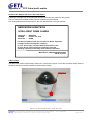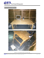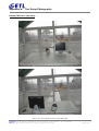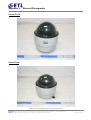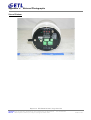
1
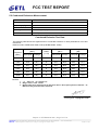
ETL Inc.
#371-51, Gasan-dong, Geumcheon-gu, Seoul, 153-803, Korea
FCC VERIFICATION CERTIFICATE
Report Issue Date
August 21, 2009
Test Report No.
ETLE080219.158.1
Test Site
FCC Registration Number: 95422
Applicant
NEW BORN HIGHTECH
Contact Person
Wang, Young-sin / R&D Assistant manager
Tel: +82-2-862-7914
Fax: +82-2-862-7920
Manufacturer
NEW BORN HIGHTECH
Product Type
INTELLIGENT DOME CAMERA
Model
NSD-S360
Multiple Model
NSD-S300, NSD-S230, NSD-S680, NSD-H350, NSD-S330,
NSD-S370, NSD-S230IP, NSD-S300IP, NSD-S330IP,
NSD-S360IP, NSD-S370IP, NSD-S680IP
FCC Rule Part(s)
Part 15 Subpart B
Classification
All Other devices
Limit Apply
FCC Part 15.107 & 15.109 Class A
The device bearing the trade name and model specified above has been shown to
comply with the applicable technical standard as indicated in the measurement report
and was tested in accordance with the measurement procedures specified in ANSI
C63.4-2003.
I attest to the accuracy of data and all measurement reported herein were performed
by me or were made under my supervision and are correct to the best of my
knowledge and belief. I assume full responsibility for the completeness of these
measurements and vouch for the qualification of all persons taking them.
Yo Han, Park
Chief Engineer
www.etl.re.kr
Electromagnetic Emission
FCC MEASUREMENT REPORT
VERIFICATION OF COMPLIANCE
FCC Part 15 Verification Measurement
PRODUCT
:
INTELLIGENT DOME CAMERA
MODEL/TYPE NO
:
NSD-S360 / NONE
Multiple Model Name
:
NSD-S300, NSD-S230, NSD-S680, NSD-H350, NSD-S330,
NSD-S370, NSD-S230IP, NSD-S300IP, NSD-S330IP,
NSD-S360IP, NSD-S370IP, NSD-S680IP
:
APPLICANT
NEW BORN HIGHTECH
Byucksan/Kyungin Digital Valley 2 1218~1220, 481-10 Gasan-dong,
Geumcheon-gu, Seoul, Korea
Attn.: Wang, Young-sin / R&D Assistant manager
:
MANUFACTURER
NEW BORN HIGHTECH
Byucksan/Kyungin Digital Valley 2 1218~1220, 481-10 Gasan-dong,
Geumcheon-gu, Seoul, Korea
FCC CLASSIFICATION
:
All Other devices
FCC RULE PART(S)
:
FCC Part 15 Subpart B
FCC PROCEDURE
:
ANSI C63.4-2003
TEST REPORT No.
:
ETLE080219.158.1
DATES OF TEST
:
February 20, 2008 to March 04, 2008
REPORT ISSUE DATE
:
August 21, 2009
TEST LABORATORY
:
ETL Inc. ( FCC Registration Number : 95422)
This INTELLIGENT DOME CAMERA, Model NSD-S360 has been tested in accordance with the
measurement procedures specified in ANSI C63.4-2003 at the ETL Test Laboratory and has been shown to
be complied with the electromagnetic radiated emission limits specified in FCC Rule Part15 Subpart B:
I attest to the accuracy of data. All measurement herein was performed by me or was made under my
supervision and is correct to the best of my knowledge and belief. I assume full responsibility for the
completeness of these measurements and vouch for the qualifications of all persons taking them.
The results of testing in this report apply to the product/system which was tested only. Other similar
equipment will not necessarily produce the same results due to production tolerance and measurement
uncertainties.
Yo Han, Park / Chief Engineer
ETL Inc.
#371-51, Gasan-dong, Geumcheon-gu, Seoul, 153-803, Korea
Tel: 82-2-858-0786 Fax: 82-2-858-0788
This report only responds to the tested sample and may not be reproduced, except in full, without written approval of the ETL Inc.
FCC TEST REPORT
Table of Contents
FCC Measurement Report
1. Introduction
2. Product Information
3. Description of Tests
4. Test Condition
5. Test Results
5.1 Summary of Test Results
5.2 Conducted Emissions Measurement
5.3 Radiated Emissions Measurement
6. Sample Calculation
7. List of test Equipment used for Measurement
Appendix A. FCC Label and Location
Appendix B. Test Setup Photographs
Appendix C. External Photographs
Appendix D. Internal Photographs
Report no. ETLE080219.158.1, Page 2 of 18
Head Office: # 371-51 Gasan-dong, Geumcheon-gu, Seoul, 153-803, Korea Tel : 82-2-858-0786
EMC Lab : #584 Sangwhal-ri, Ganam-myeon, Yoju-gun, Gyeonggi-do, 469-885, Korea
Fax : 82-2-858-0788
ETLQP-21-F23-0
FCC TEST REPORT
FCC MEASUREMENT REPORT
Scope – Measurement and determination of electromagnetic emission(EME) of radio frequency devices
including intentional radiators and/or unintentional radiators for compliance with the technical rules and
regulations of the U.S Federal Communications Commission(FCC)
General Information
Applicant Name
: NEW BORN HIGHTECH
Address
: Byucksan/Kyungin Digital Valley 2 1218~1220, 481-10
Gasan-dong, Geumcheon-gu, Seoul, Korea
Attention
: Wang, Young-sin / R&D Assistant manager
z
EUT Type :
INTELLIGENT DOME CAMERA
z
Model Number :
NSD-S360
z
S/N :
NONE
z
Frequency Range :
X-TAL Æ 18,432 MHz; 17,734475 MHz; 14,31818 MHz
z
FCC Rule Part(s) :
FCC Part 15 Subpart B
z
Test Procedure :
ANSI C63.4-2003
z
FCC Classification :
All Other devices
z
Dates of Tests :
February 20, 2008 to March 04, 2008
z
Place of Tests :
ETL Inc.Testing Lab. (FCC Registration Number : 95422)
Radiated Emission test;
584, Sangwhal-Ri, Ganam-myeon, Yoju-gun,
Gyeonggi-do, Korea
Conducted Emission test;
371-51, Gasan-dong, Geumcheon-gu, Seoul, 153-803, Korea
z
Test Report No. :
ETLE080219.158.1
Report no. ETLE080219.158.1, Page 3 of 18
Head Office: # 371-51 Gasan-dong, Geumcheon-gu, Seoul, 153-803, Korea Tel : 82-2-858-0786
EMC Lab : #584 Sangwhal-ri, Ganam-myeon, Yoju-gun, Gyeonggi-do, 469-885, Korea
Fax : 82-2-858-0788
ETLQP-21-F23-0
FCC TEST REPORT
1. INTRODUCTION
The measurement test for radiated and conducted emission test were conducted at the ETL Inc. The site is
constructed in conformance with the requirements of the ANSI C63.4-2003 and CISPR Publication 16. The ETL
has site descriptions on file with the FCC for 3 m and 10 m site configurations. Detailed description of test
facility was found to be in compliance with the requirements of Section 2.948 FCC Rules according to the ANSI
C63.4-2003 and registered to the Federal Communications Commission (Registration Number : 95422 ).
The measurement procedure described in American National Standard for Method of Measurement of RadioNoise Emission from Low-Voltage Electrical and Electronic Equipment in the Range of 9 kHz to 40 GHz (ANSI
C63.4-2003) was used in determining radiated and conducted emissions from the NEW BORN HIGHTECH
Model: NSD-S360.
Report no. ETLE080219.158.1, Page 4 of 18
Head Office: # 371-51 Gasan-dong, Geumcheon-gu, Seoul, 153-803, Korea Tel : 82-2-858-0786
EMC Lab : #584 Sangwhal-ri, Ganam-myeon, Yoju-gun, Gyeonggi-do, 469-885, Korea
Fax : 82-2-858-0788
ETLQP-21-F23-0
FCC TEST REPORT
2. PRODUCT INFORMATION
2.1 Equipment Description
The Equipment Under Test (EUT) is the NEW BORN HIGHTECH (model: NSD-S360)
The model NSD-S360 is basic model that was tested.
Model
Fitted variety zoom module
Effective Pixels No.
NSD-S360
(Basic model)
x36
410k
NSD-S300
x30
410k
NSD-S230
x23
410k
NSD-S680
x26
680k
NSD-H350
x35
410k
NSD-S330
x33
410k
NSD-S370
x37
410k
NSD-S230IP
x23
410k
NSD-S300IP
x30
410k
NSD-S330IP
x33
410k
NSD-S360IP
x36
410k
NSD-S370IP
x37
410k
NSD-S680IP
x26
680k
2.2 General Specification
• Optical zoom: 36× Zoom
• Digital zoom: Maximum 432× Zoom
• Focal length: F= 3,4 mm ~ 122,4 mm
• Expression of X, Y coordinates
• Cam memory easy to Back up & Up-Grade Firmware by DATA
• Auto compensation Pan/Tile position
• Preset and Function title setting possible (OSD function)
• Max Pan speed 400°/sec with Turbo key pressed
• Support variety surveillance mode (Pattern, Vector Scan, Tour, Group)
• Support Multiple Protocol
• Fitted variety zoom module (22×, 23×, 26×, 30×, 35×, 36×)
• Auto Tracking function (Option)
Report no. ETLE080219.158.1, Page 5 of 18
Head Office: # 371-51 Gasan-dong, Geumcheon-gu, Seoul, 153-803, Korea Tel : 82-2-858-0786
EMC Lab : #584 Sangwhal-ri, Ganam-myeon, Yoju-gun, Gyeonggi-do, 469-885, Korea
Fax : 82-2-858-0788
ETLQP-21-F23-0
FCC TEST REPORT
Effective Pixels No
Signal System
Pick-up Device
Horizontal Resolution
CAMERA
S/N Ratio
Min Illuminance
Lens
Optical Zoom
Digital Zoom
Preset
Preset Speed
Max Pan Speed
Max Tilt Speed
PAN/TILT
Panning Range
Tilting Range
Control Method
Digital Flip
Cam ID Control
Zone Function
Cam ID Change By Data
Cam Power On/Off By Data
Memory Back Up by Data
Camera Up-Grade by easy Data
Expression of X,Y coordinates
Self Check Up Function
Set Memory Pop-Up Function
Function
Zoom/Pan/Tilt Speed Coordination
Home Position
Alarm Input
SCAN
GROUP
TOUR
PATTERN
SWING
VECTOR SCAN
Operating Temp
Power Supply
Power Type
Weight
Dimension
Approx 410k
DSP / NTSC / PAL
1/4” Ex-view HAD CCD
540TV Lines
More Than 50dB
1,4lux, 0,01lux (ICR ON)
F = 3,4 mm ~ 122,4 mm
Tele - Wide ×36
Up – Down ×12(432×)
512 Position
Pan 360°, Tilt 180°/Sec
Pan 400°/Sec with Turbo key pressed
Tilt 180°/Sec
1° ~ 360° / Endless
0° ~ 180°
RS-422/485
On/Off
999 Connect
Yes (One Button Push)
Yes (With NK-2003TX)
Yes (With NK-2003TX)
Yes
Yes
Yes
Yes
Yes
Yes
Yes
5 Input 1 lelay Output
8 Programmable
6 Group
8 Tour
6 Pattern (360sec)
Yes
Yes
-10 ℃ ~ 60 ℃
DC 24 V / AC 24 V
SMPS
1,7 kg
Ø150 X 173 (H)
Report no. ETLE080219.158.1, Page 6 of 18
Head Office: # 371-51 Gasan-dong, Geumcheon-gu, Seoul, 153-803, Korea Tel : 82-2-858-0786
EMC Lab : #584 Sangwhal-ri, Ganam-myeon, Yoju-gun, Gyeonggi-do, 469-885, Korea
Fax : 82-2-858-0788
ETLQP-21-F23-0
FCC TEST REPORT
3. DESCRIPTION OF TESTS
3.1 Conducted Emission Measurement
Conducted emissions measurements were made in accordance with section 11, "Measurement of Information
Technology Equipment" of ANSI C63.4-2003. The measurements were performed over the frequency range of
0,15 MHz to 30 MHz using a 50 Ω / 50 uH LISN as the input transducer to a Spectrum Analyzer or a Test
Receiver. The measurements were made with the detector set for "Peak" amplitude within a bandwidth of 9 kHz
or for "quasi-peak" within a bandwidth of 9 kHz.
The line-conducted emission test is conducted inside a shielded anechoic chamber room with 1 m x 1,5 m x
0,8 m wooden table which is placed 0,4 m away from the vertical wall and 1,5 m away from the side wall of the
chamber room. Two LISN are bonded to the shielded room. The EUT is powered from the LISN and the support
equipment is powered from the other LISN. Power to the LISNs are filtered by a noise cut power line filters. All
electrical cables are shielded by braided tinned steel tubing with inner φ 1,2 cm. If the EUT is a DC-powered
device, power will be derived from the source power supply it normally will be powered from and these supply
lines will be connected to the LISN. Non-inductive bundling to a 1 m length shortened all interconnecting cables
more than 1 m. Sufficient time for the EUT, support equipment, and test equipment was allowed in order for
them to warm up to their normal operating condition. The RF output of the LISN was connected to the EMI Test
Receiver to determine the frequency producing the maximum emission from the EUT. The frequency producing
the maximum level was reexamined using to set Quasi-Peak mode by manual, after scanned by automatic Peak
mode from 0,15 MHz to 30 MHz. The bandwidth of the spectrum analyzer was set to 9 kHz. The EUT, support
equipment, and interconnecting cables were arranged and manipulated to maximize each emission.
Photographs of the worst-case emission can be seen in photographs of conducted emission test setup in
Appendix B.
Report no. ETLE080219.158.1, Page 7 of 18
Head Office: # 371-51 Gasan-dong, Geumcheon-gu, Seoul, 153-803, Korea Tel : 82-2-858-0786
EMC Lab : #584 Sangwhal-ri, Ganam-myeon, Yoju-gun, Gyeonggi-do, 469-885, Korea
Fax : 82-2-858-0788
ETLQP-21-F23-0
FCC TEST REPORT
3.2 Radiated Emission Measurement
Radiated emission measurements were made in accordance with section 11, "Measurement of Information
Technology Equipment" of ANSI C63.4-2003. The measurements were performed over the frequency range of
30 MHz to 1 GHz using antenna as the input transducer to a spectrum analyzer or a field intensity meter. The
measurements were made with the detector set for "Quasi-peak" within a bandwidth of 120 kHz.
Preliminary measurements were made at 3 m using broadband antennas, and spectrum analyzer to
determined the frequency producing the maximum emission in shielded room. Appropriate precaution was taken
to ensure that all emission from the EUT were maximized and investigated. The system configuration, mode of
operation, turntable azimuth and height with respect to the antenna were noted for each frequency found. The
spectrum was scanned from 30 MHz to 1 000 MHz using Log-Bicon antenna. Above 1 GHz, linearly polarized
double ridge horn antennas were used. Final measurements were made open site at 10 m. The test equipment
was laced on a wooden turn-table. Sufficient time for the EUT, support equipment, and test equipment was
allowed in order for them to warm up to their normal operating condition. Each frequency found during pre-scan
measurements was re-examined by manual. The detector function was set to CISPR Quasi-peak mode and the
bandwidth of the receiver was set to 120 kHz or 1 MHz depending on the frequency of type of signal. The EUT,
support equipment and interconnecting cables were re-configured to the set-up producing the maximum
emission for the frequency and were placed on top of a 0,8 m high nonmetallic 1 m x 1,5 m table. The EUT,
support equipment, and interconnecting cables were re-arranged and manipulated to maximize each emission.
The turntable containing the system was rotated; the antenna height was varied 1 m to 4 m and stopped at the
azimuth or height producing the maximum emission. Each emission was maximized by: varying the mode of
operation to the EUT and/or support equipment and changing the polarity of the antenna, whichever determined
the worst-case emission.
Photographs of the worst-case emission can be seen in Photographs of the worst-case emission test setup
can be seen in Appendix B.
Report no. ETLE080219.158.1, Page 8 of 18
Head Office: # 371-51 Gasan-dong, Geumcheon-gu, Seoul, 153-803, Korea Tel : 82-2-858-0786
EMC Lab : #584 Sangwhal-ri, Ganam-myeon, Yoju-gun, Gyeonggi-do, 469-885, Korea
Fax : 82-2-858-0788
ETLQP-21-F23-0
FCC TEST REPORT
4. TEST CONDITION
4.1 Test Configuration
The device was configured for testing in a typical fashion (as a customer would normally use it). During the
tests, the following conditions and configurations were used.
4.2 EUT operation
Operating Mode
The worst operating condition
- Camera image display mode
X
- Camera image display mode and lens angle point auto mode
◎
◎ : Worst case investigated during the test.
4.3 Support Equipment Used
Following peripheral devices and interface cables were connected during the measurement:
Description
Model Name
Serial No.
Manufacturer
LCD TV Monitor
OR940S
NONE
ORION
Adapter
(for LCD TV Monitor)
DA-48M12
Y321207211003819700
Asian Power Devices Inc.
DC power supply
E3616A
KR64301658
HP
Report no. ETLE080219.158.1, Page 9 of 18
Head Office: # 371-51 Gasan-dong, Geumcheon-gu, Seoul, 153-803, Korea Tel : 82-2-858-0786
EMC Lab : #584 Sangwhal-ri, Ganam-myeon, Yoju-gun, Gyeonggi-do, 469-885, Korea
Fax : 82-2-858-0788
ETLQP-21-F23-0
FCC TEST REPORT
4.4 Type of Cables Used
- Power Supply Type: DC 24 V
Device from
Device to
Type of Cable(Port)
Length(m)
Type of shield
EUT
LCD TV Monitor
Video Out
>3,0
Shielded
EUT
Termination
RS-485/422
>3,0
Unshielded
EUT
Termination
AUX
>3,0
Unshielded
EUT
Termination
SENSOR
>3,0
Unshielded
EUT
DC power supply
AC/DC Input
1,0
Unshielded
LCD TV Monitor
Adapter
DC Input
1,2
Shielded
Device from
Device to
Type of Cable(Port)
Length(m)
Type of shield
EUT
LCD TV Monitor
VIDEO OUT
>3,0
Shielded
EUT
Termination
RS-485/422
>3,0
Unshielded
EUT
Termination
AUX
>3,0
Unshielded
EUT
Termination
SENSOR
>3,0
Unshielded
EUT
Power socket
AC/DC Input
1,0
Unshielded
LCD TV Monitor
Adapter
DC Input
1,2
Shielded
- Power Supply Type: AC 24 V
Report no. ETLE080219.158.1, Page 10 of 18
Head Office: # 371-51 Gasan-dong, Geumcheon-gu, Seoul, 153-803, Korea Tel : 82-2-858-0786
EMC Lab : #584 Sangwhal-ri, Ganam-myeon, Yoju-gun, Gyeonggi-do, 469-885, Korea
Fax : 82-2-858-0788
ETLQP-21-F23-0
FCC TEST REPORT
4.5 The setup drawing(s)
- Power Supply Type: DC 24 V
DC power
supply
LCD TV Monitor
EUT
- Power Supply Type: AC 24 V
EUT
LCD TV Monitor
: Data Line
: Power Line
: Termination
: Adapter
Report no. ETLE080219.158.1, Page 11 of 18
Head Office: # 371-51 Gasan-dong, Geumcheon-gu, Seoul, 153-803, Korea Tel : 82-2-858-0786
EMC Lab : #584 Sangwhal-ri, Ganam-myeon, Yoju-gun, Gyeonggi-do, 469-885, Korea
Fax : 82-2-858-0788
ETLQP-21-F23-0
FCC TEST REPORT
5. TEST RESULTS
5.1 Summary of Test Results
The measurement results were obtained with the EUT tested in the conditions described in this report. Detailed
measurement data and plots showing the maximum emission of the EUT are reported.
FCC Rules
Measurement Required
Result
15.107
Conducted Emissions Measurement
Passed by 20,70 dB
15.109
Radiated Emissions Measurement
Passed by
8,80 dB
The data collected shows that the NEW BORN HIGHTECH INTELLIGENT DOME CAMERA, NSD-S360 complies
with technical requirements of above rules part 15.107 and 15.109 Class A.
The equipment is not modified anything, mechanical or circuits to improve EMI status during a measurement.
No EMI suppression device(s) was added and/or modified during testing.
Report no. ETLE080219.158.1, Page 12 of 18
Head Office: # 371-51 Gasan-dong, Geumcheon-gu, Seoul, 153-803, Korea Tel : 82-2-858-0786
EMC Lab : #584 Sangwhal-ri, Ganam-myeon, Yoju-gun, Gyeonggi-do, 469-885, Korea
Fax : 82-2-858-0788
ETLQP-21-F23-0
FCC TEST REPORT
5.2 Conducted Emissions Measurement
EUT
INTELLIGENT DOME CAMERA / NSD-S360 (S/N: N/A)
Limit apply to
FCC Part 15.107 Class A
Power Supply Type
AC 24 V
Test Date
March 03, 2008
Operating Condition
Camera image display mode and lens angle point auto mode
Result
Passed by 20,70 dB
Conducted Emission Test Data
The following table shows the highest levels of conducted emissions on both polarizations of hot and
neutral line.
Detector mode: CISPR Quasi-Peak mode (6 dB Bandwidth: 9 kHz)
Result
[dB㎶]
Frequency
[MHz]
Quasi-peak
Average
0,270
52,5
26,7
0,380
53,6
0,490
Phase
(*L/**N)
Limit
[dB㎶]
Margin
[dB]
Quasi-peak
Average
Quasi-peak
Average
H
79,0
66,0
26,6
37,3
40,3
H
79,0
66,0
25,4
25,7
52,7
28,7
H
79,0
66,0
26,3
37,3
0,805
52,3
37,3
H
73,0
60,0
20,7
22,7
3,260
45,3
30,7
H
73,0
60,0
27,7
29,3
16,250
38,7
26,5
H
73,0
60,0
34,4
33,5
NOTES:
1.
2.
3.
* H : HOT Line , **N : Neutral Line
Margin value = Limit – Result
Measurement were performed at the AC Power Inlet in the frequency band of 150 kHz ~ 30
MHz according to the FCC Part 15 Class A.
Test Engineer : Hyung-min, Choi
Report no. ETLE080219.158.1, Page 13 of 18
Head Office: # 371-51 Gasan-dong, Geumcheon-gu, Seoul, 153-803, Korea Tel : 82-2-858-0786
EMC Lab : #584 Sangwhal-ri, Ganam-myeon, Yoju-gun, Gyeonggi-do, 469-885, Korea
Fax : 82-2-858-0788
ETLQP-21-F23-0
FCC TEST REPORT
Line: HOT Line
Limit:
Quasi-Peak
Average
Line: Neutral Line
Quasi-peak
Average
Report no. ETLE080219.158.1, Page 14 of 18
Head Office: # 371-51 Gasan-dong, Geumcheon-gu, Seoul, 153-803, Korea Tel : 82-2-858-0786
EMC Lab : #584 Sangwhal-ri, Ganam-myeon, Yoju-gun, Gyeonggi-do, 469-885, Korea
Fax : 82-2-858-0788
ETLQP-21-F23-0
FCC TEST REPORT
5.3 Radiated Emissions Measurement
EUT
INTELLIGENT DOME CAMERA / NSD-S360 (S/N: N/A)
Limit apply to
FCC Part 15.109 Class A
Power Supply Type
DC 24 V
Test Date
March 03, 2008
Operating Condition
Camera image display mode and lens angle point auto mode
Result
Passed by 8,80 dB
Radiated Emission Test Data
The following table shows the highest levels of radiated emissions on both polarizations of horizontal and vertical.
Detector mode: CISPR Quasi – Peak mode (6 dB Bandwidth: 120 kHz)
Frequency
[MHz]
Reading
[dBµV]
Polarization Ant. Factor Cable Loss
Result
(*H/**V)
[dB/m]
[dB]
[dBµV/m]
Limit
[dBµV/m]
Margin
[dB]
48,41
9,38
V
9,65
2,07
21,10
39,00
17,90
114,53
19,47
V
10,14
2,99
32,60
43,50
10,90
128,83
18,31
V
10,86
3,23
32,40
43,50
11,10
143,17
18,89
V
11,36
3,45
33,70
43,50
9,80
171,82
20,29
V
10,59
3,82
34,70
43,50
8,80
229,07
7,94
V
10,67
4,59
23,20
46,44
23,24
NOTES:
1.
2.
3.
4.
* H: Horizontal polarization, ** V: Vertical polarization
Result = Reading + Antenna factor + Cable loss
Margin value = Limit - Result
The measurement was performed for the frequency range 30 MHz ~ 1 000 MHz according to the
FCC Part 15.109 Class A.
Test Engineer: Hyung-min, Choi
Report no. ETLE080219.158.1, Page 15 of 18
Head Office: # 371-51 Gasan-dong, Geumcheon-gu, Seoul, 153-803, Korea Tel : 82-2-858-0786
EMC Lab : #584 Sangwhal-ri, Ganam-myeon, Yoju-gun, Gyeonggi-do, 469-885, Korea
Fax : 82-2-858-0788
ETLQP-21-F23-0
FCC TEST REPORT
EUT
INTELLIGENT DOME CAMERA / NSD-S360 (S/N: N/A)
Limit apply to
FCC Part 15.109 Class A
Power Supply Type
AC 24 V
Test Date
February 29, 2008
Operating Condition
Camera image display mode and lens angle point auto mode
Result
Passed by 9,70 dB
Radiated Emission Test Data
The following table shows the highest levels of radiated emissions on both polarizations of horizontal and vertical.
Detector mode: CISPR Quasi – Peak mode (6 dB Bandwidth: 120 kHz)
Frequency
[MHz]
Reading
[dBµV]
Polarization Ant. Factor Cable Loss
Result
(*H/**V)
[dB/m]
[dB]
[dBµV/m]
Limit
[dBµV/m]
Margin
[dB]
114,53
20,67
V
10,14
2,99
33,80
43,50
9,70
128,84
18,41
V
10,86
3,23
32,50
43,50
11,00
143,17
18,79
V
11,36
3,45
33,60
43,50
9,90
157,48
7,79
V
11,35
3,66
22,80
43,50
20,70
171,81
18,09
V
10,59
3,82
32,50
43,50
11,00
200,43
15,05
V
9,84
4,01
28,90
43,50
14,60
NOTES:
1.
2.
3.
4.
* H: Horizontal polarization, ** V: Vertical polarization
Result = Reading + Antenna factor + Cable loss
Margin value = Limit - Result
The measurement was performed for the frequency range 30 MHz ~ 1 000 MHz according to the
FCC Part 15.109 Class A.
Test Engineer: Hyung-min, Choi
Report no. ETLE080219.158.1, Page 16 of 18
Head Office: # 371-51 Gasan-dong, Geumcheon-gu, Seoul, 153-803, Korea Tel : 82-2-858-0786
EMC Lab : #584 Sangwhal-ri, Ganam-myeon, Yoju-gun, Gyeonggi-do, 469-885, Korea
Fax : 82-2-858-0788
ETLQP-21-F23-0
FCC TEST REPORT
6. SAMPLE CALCULATION
Sample Field Strength Calculation
The field strength is calculated by adding the Antenna Factor and Cable Factor.
The basic equation with a sample calculation is as follows:
FS = RA + AF + CF
Where FS = Field Strength
RA = Receiver Amplitude
AF = Antenna Factor
CF = Cable Attenuation Factor
dB(μV) = 20 log10 (uV) : Equation
Example
: @ 171,82 MHz
Class A Limit
= 43,50 dBuV/m
Reading
= 20,29 dBuV
Antenna Factor + Cable Loss
Total
Margin
= 10,59 + 3,82 = 14,41 dBuV/m
= 34,70 dBuV/m
= 43,50 – 34,70 = 8,80 dB
= 8,80 dB below Limit
Report no. ETLE080219.158.1, Page 17 of 18
Head Office: # 371-51 Gasan-dong, Geumcheon-gu, Seoul, 153-803, Korea Tel : 82-2-858-0786
EMC Lab : #584 Sangwhal-ri, Ganam-myeon, Yoju-gun, Gyeonggi-do, 469-885, Korea
Fax : 82-2-858-0788
ETLQP-21-F23-0
FCC TEST REPORT
7. List of test equipments used for measurements
Test Equipment
Model
Mfg.
Serial No.
Cal. Due Date
EMI TEST Receiver
ESVS 10
R&S
835165/001
08.05.03
EMI TEST Receiver
ESHS 30
R&S
840190/002
09.02.25
LISN
3816-2
EMCO
1001
08.10.04
LISN
3816-2
EMCO
1002
08.10.04
LogBicon Antenna
VULB9165
Schwarzbeck
2023
08.09.03
Turn-Table
DETT-03
Daeil EMC
-
N/A
Antenna Master
DEAM-03
Daeil EMC
-
N/A
Report no. ETLE080219.158.1, Page 18 of 18
Head Office: # 371-51 Gasan-dong, Geumcheon-gu, Seoul, 153-803, Korea Tel : 82-2-858-0786
EMC Lab : #584 Sangwhal-ri, Ganam-myeon, Yoju-gun, Gyeonggi-do, 469-885, Korea
Fax : 82-2-858-0788
ETLQP-21-F23-0
Appendix A.
FCC Label and Location
Product Label Sample with FCC Label information
Following is a sample copy of the label that will be placed on the rear cabinet of the product.
The FCC Label and compliance statement are marked in the product label.
The warning statement and Information to the User are described in the user manual.
NEW BORN HIGHTECH
INTELLIGENT DOME CAMERA
Model No. : NSD-S360
POWER
: DC 24 V; AC 24 V
Serial No. : NONE
This device complies with part 15 of the FCC Rules. Operation
is subject to the following two conditions:
(1) This device may not cause harmful interference, and
(2) This device must accept any interference received,
including interference that may cause undesired operation.
Manufacturer: NEW BORN HIGHTECH
Made in Korea
Label Location
The label shown shall be permanently affixed at a conspicuous location on the device and be readily visible to
the user at the time purchase.(Labeling requirements per 2.925)
Label here
Report no. ETLE080219.158.1, Page A1 of A1
Head Office: # 371-51 Gasan-dong, Geumcheon-gu, Seoul, 153-803, Korea Tel : 82-2-858-0786
EMC Lab : #584 Sangwhal-ri, Ganam-myeon, Yoju-gun, Gyeonggi-do, 469-885, Korea
Fax : 82-2-858-0788
ETLQP-21-F23-0
Appendix B. Test Setup Photographs
Conducted Emission Test Setup
Report no. ETLE080219.158.1, Page B1 of B2
Head Office: # 371-51 Gasan-dong, Geumcheon-gu, Seoul, 153-803, Korea Tel : 82-2-858-0786
EMC Lab : #584 Sangwhal-ri, Ganam-myeon, Yoju-gun, Gyeonggi-do, 469-885, Korea
Fax : 82-2-858-0788
ETLQP-21-F23-0
Appendix B. Test Setup Photographs
Radiated Emission Test Setup
Report no. ETLE080219.158.1, Page B2 of B2
Head Office: # 371-51 Gasan-dong, Geumcheon-gu, Seoul, 153-803, Korea Tel : 82-2-858-0786
EMC Lab : #584 Sangwhal-ri, Ganam-myeon, Yoju-gun, Gyeonggi-do, 469-885, Korea
Fax : 82-2-858-0788
ETLQP-21-F23-0
Appendix C. External Photographs
View of Front
View of Rear
Report no. ETLE080219.158.1, Page C1 of C2
Head Office: # 371-51 Gasan-dong, Geumcheon-gu, Seoul, 153-803, Korea Tel : 82-2-858-0786
EMC Lab : #584 Sangwhal-ri, Ganam-myeon, Yoju-gun, Gyeonggi-do, 469-885, Korea
Fax : 82-2-858-0788
ETLQP-21-F23-0
Appendix C. External Photographs
View of Bottom
Report no. ETLE080219.158.1, Page C2 of C2
Head Office: # 371-51 Gasan-dong, Geumcheon-gu, Seoul, 153-803, Korea Tel : 82-2-858-0786
EMC Lab : #584 Sangwhal-ri, Ganam-myeon, Yoju-gun, Gyeonggi-do, 469-885, Korea
Fax : 82-2-858-0788
ETLQP-21-F23-0
Appendix D. Internal Photographs
Inside view of EUT
Report no. ETLE080219.158.1, Page D1 of D1
Head Office: # 371-51 Gasan-dong, Geumcheon-gu, Seoul, 153-803, Korea Tel : 82-2-858-0786
EMC Lab : #584 Sangwhal-ri, Ganam-myeon, Yoju-gun, Gyeonggi-do, 469-885, Korea
Fax : 82-2-858-0788
ETLQP-21-F23-0