1
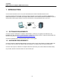
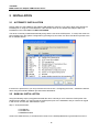
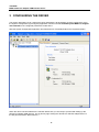
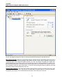
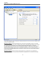
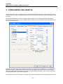
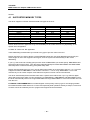
7TS7USB
IGSS Simatic PC Adapter USB Interface Driver
User’s Manual
Seven Technologies
7-Technologies A/S * Bistruphave 3 * DK-3460 Birkerød * Denmark
Phone: +45 45 900 700 * Fax: +45 45 900 701 * CVR no. DK 73 63 41 13
E-mail: [email protected] World Wide Web: http://www.7t.dk
7TS7USB
IGSS Simatic PC Adapter USB Interface driver
DISCLAIMER
:
This is an unpublished work, the copyright of which vests in
SEVEN TECHNOLOGIES A/S.
All rights reserved.
The information contained herein is the property of SEVEN
TECHNOLOGIES and is supplied without liability for errors or omissions.
No part may be reproduced or used except as authorised by contract or
other written permission.
The copyright and the foregoing restriction on reproduction and use extend
to all media in which the information may be embodied.
- 1-
7TS7USB
IGSS Simatic PC Adapter USB Interface driver
CONTENTS:
1
2
3
4
5
6
INTRODUCTION ................................................................................................................. 3
1.1
Software Requirements .......................................................................................... 3
1.2
Hardware Requirements ......................................................................................... 3
INSTALLATION ................................................................................................................... 4
2.1
Automatic Installation.............................................................................................. 4
2.2
Manual Installation .................................................................................................. 4
CONFIGURING THE DRIVER ............................................................................................ 6
CONFIGURING THE OBJECTS ....................................................................................... 11
4.1
Supported Memory Types .................................................................................... 12
PERFORMANCE AND THROUGHPUT ........................................................................... 13
ERROR CODES ................................................................................................................ 14
- 2-
7TS7USB
IGSS Simatic PC Adapter USB Interface driver
1 INTRODUCTION
This document describes how to set up and troubleshoot the IGSS 7TS7USB Interface Driver.
The driver implements the Simatic S7 protocol stack required to use a Simatic PC Adapter USB with the
IGSS SCADA system. The Simatic PC Adapter USB enables communication between a standard PC (with a
USB interface) and Simatic S7/300, S7/400 and S7/1200 PLC using the MPI/DP port on the PLC.
1.1 SOFTWARE REQUIREMENTS
The driver requires "SIMATIC PC Adapter USB Software" (Version 2.0 or higher) from Siemens to be
installed on the PC. This driver is delivered with the Simatic PC Adapter USB or it might be downloaded from
Siemens using this link: http://support.automation.siemens.com.
The driver is designed to be used with IGSS version 8.0 and higher.
1.2 HARDWARE REQUIREMENTS
The driver requires a standard USB interface on the PC used to connect the Simatic PC Adapter USB to the
PC. Please refer to Simatic PC Adapter USB documentation for cabling, setup and wiring instructions.
The driver also requires a Simatic PC Adapter USB device (Siemens part number 6ES7972-0CB20-0XA0).
Any S7/300, S7/400 or S7/1200 series PLC with an MPI port.
- 3-
7TS7USB
IGSS Simatic PC Adapter USB Interface driver
2 INSTALLATION
2.1 AUTOMATIC INSTALLATION
Please make sure that "SIMATIC PC Adapter USB Software" (Version 2.0 or higher) driver from Siemens is
installed prior to using the 7TS7USB driver. If the Siemens driver for the Simatic PC Adapter USB is not
installed then the 7TS7USB driver WILL NOT WORK.
The driver is normally installed automatically along with the rest of the IGSS system. To verify if the driver has
been installed open the System Configuration (sysconfig.exe) and check if a driver with ID:86 is present in the
list of available drivers:
If the driver is present then you can proceed to the next section: “Configuring the Driver”, otherwise install the
driver using the manual installation procedure described below.
2.2 MANUAL INSTALLATION
Using the following step-by-step guide will install the driver manually on a PC where the IGSS system has
already been installed. You need to stop the IGSS system prior to the installation and you need to be logged
in with a user account with “Administrator” rights.
Step 1: Verify that the files:
7TS7USB.DLL
7TS7USBc.DLL
COMMDRV86.REG
exists in the GSS\ directory. If the files doesn’t exists run the IGSSUpdateClient to get the files from the 7T
- 4-
7TS7USB
IGSS Simatic PC Adapter USB Interface driver
WEB server – or contact 7T Support ([email protected]) to get the files via e-mail.
Step 2: Double-click on the COMMDRV86.REG file to import the registry settings needed for the system to
recognize the driver.
The driver is now installed.
- 5-
7TS7USB
IGSS Simatic PC Adapter USB Interface driver
3 CONFIGURING THE DRIVER
This section describes how to configure the driver parameters. All parameters must be configured by using
the System Configuration (sysconfig.exe) application. Please note that the IGSS system MUST be stopped
and restarted for the configured parameters to take effect.
Start the System Configuration application and add the driver 7TS7USB (ID:86) to the requested station.
When the driver has been added to the relevant station then you are ready to proceed with setting up the
Simatic PC Adapter USB network. This is done by right clicking the "Simatic S7 USB PC Adapter driver" in
the left pane and select "New Interface...":
- 6-
7TS7USB
IGSS Simatic PC Adapter USB Interface driver
On the “PC Adapter Parameters” page you specify the network parameters for the MPI network:
MPI network baudrate: Select the required MPI network baudrate which the PC adapter should use when it
is connected to the MPI network (typically the MPI network will only consist of the PC Adapter and the PLC).
The default value is 187,5 kb/sec for all MPI networks. If you are connecting to a ProfiBus DP network with
another baudrate that 187,5 kb/sec then be sure to follow the Siemens general guidelines for setting correct
BUS parameters otherwise connecting the PC Adapter might cause your network to fail. If you are not sure
which baudrate to use then select 187,5 kb/sec, or use your Siemens Programming tool (Step7) to see what
parameters has been set for MPI port on the PLC.
Highest station address: Select this highest station address (also sometimes just called HSA) for the MPI
network. The default value is 31. If you are not sure which HSA to use then select 31, or use your Siemens
Programming tool (Step7) to see what parameters has been set for MPI port on the PLC.
- 7-
7TS7USB
IGSS Simatic PC Adapter USB Interface driver
MPI Address: Select the MPI address which the PC adapter should have on the MPI network. Normally this
can be set to 1, but it is VERY important that the PC Adapter is not configured with the same MPI address as
any of the other nodes on the network since an MPI address MUST BE UNIQUE. Also be sure to select the
MPI address of the PC Adapter to a value less than the HSA.
Telegram retries: Here you can specify the number of telegram reties the driver should use before issuing a
communication fault. The default value is 3 which suit most applications. If you experience frequent
communication faults you might try to increase this parameter. Please be aware that the UDP/IP protocol
doesn’t guarantee delivery, and might thus be subject to lost telegrams on the network without send and/or
receiver will know about it.
Once you have set up the MPI network parameters for the PC Adapter you are ready to proceed with setting
up the PLC node. Right-click on the “Channel 0 (POLLED)” tag in the left mode tree view and select “New
Node…” in the popup menu:
The “Node Properties” appears.
- 8-
7TS7USB
IGSS Simatic PC Adapter USB Interface driver
On the “Node Properties” page you specify the network parameters for the PLC which the PC Adapter should
connect to on the MPI network.
MPI Network Address: Select the MPI address of the PLC which the PC adapter connect to on the MPI
network (i.e. the PLC which you want to read/write values from/to). Normally the MPI address of the PLC will
be 2 unless you have changed this using the Simatic Programming Software (Step7) to change the
preconfigured MPI address of the PLC. It is VERY important that the PLC Adapter is not configured with the
same MPI address as any of the other nodes - including the PC Adapter - on the network since an MPI
address MUST BE UNIQUE. Also be sure to select the MPI address of the PLC to a value less than the HSA.
If you are not sure which MPI address the PLC has then you can use some of the tools included in Step7 to
identify the MPI address.
MPI Network Segment: Select the network segment parameter. This parameter is only applicable to
segmented networks and it is only provided for backwards compatibility and is not used by the 7TS7USB
- 9-
7TS7USB
IGSS Simatic PC Adapter USB Interface driver
driver. Set this value to the default value: 1.
CPU Slot Number: This parameter MUST be set to the slot number where the PLC CPU is located in the
rack. Normally this will be 2 or 3 for S7/400 systems and 2 for S7/300 systems, but it does depend on the
actual PLC configuration and especially on how many slots the PLC power supply occupies in the rack. If you
are not sure which slot number the CPU is located in then use the Hardware setup tool in Step7 to identify
this parameter.
CPU Rack Number: This parameter MUST be set to the rack number where the PLC CPU is located.
Normally this will be 0. If you are not sure which rack number the CPU is located in then use the Hardware
setup tool in Step7 to identify this parameter.
- 10 -
7TS7USB
IGSS Simatic PC Adapter USB Interface driver
4 CONFIGURING THE OBJECTS
Once the driver and the PLC nodes have been defined, IGSS Objects and Atoms can be linked to process
variable in the PLC. Various different types of PLC memory can be accessed for read/write operations using
the driver.
By using the “Edit Mapping” tab in the object properties dialog you can specify the binding between the
object’s atoms and the PLC process variables. Start by selecting an atom and select the 7TS7USB driver in
the “Driver” drop down list:
Now select the desired PLC node number and continue by setting be desired Data Area. Then specify the
Data Block Number, Addressing and Offset within the selected Data Area. Note that the corresponding
Mnemonic is displayed and updated as you select the appropriate parameters. This is a help to make sure
you always bind to the correct process variable.
Continue this process for each atom on the object and save the parameters by clicking the OK button when
- 11 -
7TS7USB
IGSS Simatic PC Adapter USB Interface driver
finished.
4.1 SUPPORTED MEMORY TYPES
The driver supports a number of different data area types in the PLC:
Data Area
DB (Data Block)
DI (Instance Data Block)
Q (Output)
I (Input)
T (Timer Value)
C (Counter Value)
M (Flags)
Q (Output)
I (Input)
16-Bit
R/W
R/W
R/W
R/W
R/W
R/W
R/W
R/W
R/W
8-Bit
R/W
R/W
R/W
R/W
N/A
N/A
R/W
R/W
R/W
1-Bit
R/W
N/A
N/A
N/A
N/A
N/A
N/A
N/A
N/A
Please observe that the applicable range and availability for each Data Area will vary depending on the
specific PLC configuration.
R: Read. W: Write. N/A: Not Applicable.
These addressing methods allow you to bind to any type of process value in the PLC.
Please note that if you want to bind to a 32 bit (DWORD) value then use word addressing and specify the
external type as one of the supported 32 bit types, then the system will automatically do the correct
addressing.
If you e.g. want to bind to a floating point process value at DB50.DBD4 you should specify: DB50.DBW4 and
select the external type FLOAT. Then the Driver will automatically fetch both DB50.DBW4 and DB50.DBW6
and interpret the content as a floating point (IEEE float) value.
Please note that all bit types are *only* one bit values when written as a command to the PLC. I.e. if you bind
a digital command to DB50.DBX4.1 and send the command “->1” then *only* DB50.DBX4.1 is set. This
means that you can’t send complex commands that require more than one bit to be set/reset.
The driver automatically fetches at least 8 bits when a specific bit is referenced. If you e.g. define a digital
object which mimics the state of 3 bits combined (e.g. DB50.DBX6.1, DB50.DBX6.5 and DB50.DBX6.7) then
the driver automatically fetches the range DB50.DBX6.0 through DB50.DBX6.7 to ensure that all bits are read
from the PLC.
IT IS HIGHLY RECOMMENTED to use Data Register as the primary memory type for exchanging variable
information between IGSS and the PLC. Read- and especially write operations directly to Output, Timers and
Counters cannot be verified by the PLC program and might thus lead to hazards.
- 12 -
7TS7USB
IGSS Simatic PC Adapter USB Interface driver
5 PERFORMANCE AND THROUGHPUT
The driver is designed for maximum throughput using the PC USB port. On a standard PC with a standard
USB port you should expect a throughput of 15+ request/response cycles pr. second.
IMPORTANT NOTICE: The IGSS communication engine optimizes communication throughput by seeking to
group data whenever possible. This means that if the communication engine is required to read e.g.
DB100.DBW2 and DB100.DBW88 then it will read data registers DB100.DBW2, DB100.DBW4, … ,
DB100.DBW88 as a block. This is much more efficient than reading the two data registers using two
separate read requests.
- 13 -
7TS7USB
IGSS Simatic PC Adapter USB Interface driver
6 ERROR CODES
This section describes the error codes specific to the IGSS 7TS7USB interface driver.
While troubleshooting communication- or addressing problems the Driver Test Application might be useful to
display error codes reported by the driver.
0x5601:
_7TS7USB_OPEN_DEVICE_FAILED
Cause: Failed to open handle to USB device.
Action: Check that the Simatic driver the adapter is installed and functional (Use Control Panel and Device
Manager in Windows). Check that the adapter diodes (USB, MPI and Power) are on. Check the driver log for
any additional information. Reset the USB adapter by disconnecting it from the MPI bus, wait a few seconds
and then reconnect it again.
Subcode: N/A
0x5602:
_7TS7USB_STARTUP_DEVICE_FAILED
Cause: Failed to send data to USB device.
Action: Check that the adapter is connected correctly. Check that the Simatic driver the adapter is installed
and functional (Use Control Panel and Device Manager in Windows). Check that the adapter diodes (USB,
MPI and Power) are on. Check the driver log for any additional information. Reset the USB adapter by
disconnecting it from the MPI bus, wait a few seconds and then reconnect it again.
Subcode: The subcode contains the standard Windows error code.
0x5603:
_7TS7USB_START_TOOL_FAILED
Cause: Failed to start the adapter
Action: Check that the adapter BUS parameters (i.e. MPI Address, HSA and Baudrate) are set correctly.
Check that the adapter diodes (USB, MPI and Power) are on. Check the driver log for any additional
information.
Subcode: The subcode contains the standard Windows error code.
0x5604:
_7TS7USB_LOAD_TOOL_1_FAILED
Cause: Failed to download parameters to the adapter
Action: Check the driver log for any additional information. Call or e-mail 7-Technologies Technical Support
Team for advice.
Subcode: The subcode contains the standard Windows error code.
0x5605:
_7TS7USB_LOAD_TOOL_2_FAILED
Cause: Failed to download parameters to the adapter
Action: Check the driver log for any additional information. Call or e-mail 7-Technologies Technical Support
Team for advice.
Subcode: The subcode contains the standard Windows error code.
0x5606:
_7TS7USB_LOAD_TOOL_3_FAILED
Cause: Failed to download parameters to the adapter
- 14 -
7TS7USB
IGSS Simatic PC Adapter USB Interface driver
Action: Check the driver log for any additional information. Call or e-mail 7-Technologies Technical Support
Team for advice.
Subcode: The subcode contains the standard Windows error code.
0x5607:
_7TS7USB_CONNECT_FAILED
Cause: Failed to connect Simatic PC Adapter USB device to the PLC on the MPI bus
Action: Check the driver log for any additional information. Call or e-mail 7-Technologies Technical Support
Team for advice.
Subcode: The subcode contains the standard Windows error code.
0x5608:
_7TS7USB_PDU_IO_FAILED
Cause: Failed to send/receive S7 telegram to/from the PLC.
Action: Check the driver log for any additional information. Call or e-mail 7-Technologies Technical Support
Team for advice.
Subcode: The subcode contains the standard Windows error code.
0x5609:
_7TS7USB_WRONG_SIZE_CODE_READ
Cause: Unsupported size code (only bits/bytes and words supported)
Action: Check addresses in configuration
Subcode: Size code
0x560A:
_7TS7USB_WRONG_TYPE_CODE_READ
Cause: Unsupported type code (only DB/DI/A/E/TIM/CNT/MERKER supported)
Action: Check addresses in configuration
Subcode: Type code
0x560B:
_7TS7USB_S7_NO_DATA_REPLY
Cause: Received PDU with no data
Action: Check that requested data area exists
Subcode: N/A
0x560C: _7TS7USB_S7_PDU_FORMAT_ERROR
Cause: Received PDU with unexpected format
Action: Check driver Log file for additional information
Subcode: N/A
0x560D: _7TS7USB_S7_PDU_SEQ_ERROR
Cause: Received PDU with unexpected sequence number
Action: Check that MPI bus is working OK. If problem persists contact 7T technical support.
Subcode: N/A
0x560E:
_7TS7USB_WRONG_SIZE_CODE_WRITE
- 15 -
7TS7USB
IGSS Simatic PC Adapter USB Interface driver
Cause: Unsupported size code (only bits/bytes and words supported)
Action: Check addresses in configuration
Subcode: Size code
0x560F: _7TS7USB_WRONG_TYPE_CODE_WRITE
Cause: Unsupported type code (only DB/DI/A/E/TIM/CNT/MERKER supported)
Action: Check addresses in configuration
Subcode: Type code
0x0028: PLC System Error
Cause: This error type is reported if the PLC returns an error upon a read/write request from the driver. The
reason for this type of error depend on the specific error code returned from the PLC. The most common
errors are:
0x0006:
0x000A:
0x0005
0x0007
0x0001
0x8000
0x8001
0x8101
0x8103
0x8104
0x8105
0x8106
0x8107
0x810A
0x8301
0x8404
0x8500
0x8702
0xd201
0xd202
0xd203
0xd204
0xd205
0xd206
0xd207
0xd209
0xd20e
0xd210
0xd240
0xd241
0xd401
0xd402
0xd406
0xd409
The CPU does not support reading a bit block of length <> 1
The desired item is not available in the PLC. E.g. reading from a non existing DB or a DB which
is too short
The desired address is beyond limit for this PLC
Write data size error
No data from I/O module
Function already occupied
Not allowed in current operating status
Hardware fault
Object access not allowed
Context is not supported
Invalid address
Data type not supported
Data type not consistent
Object does not exist
Insufficient CPU memory ?
Severe error ?
Incorrect PDU size
Address invalid
Block name syntax error
Syntax error function parameter
Syntax error block type
No linked block in storage medium
Object already exists
Object already exists
Block exists in EPROM
Block does not exist
No block present
Block number too big
Unfinished block transfer in progress
Protected by password
Invalid SZL ID
Invalid SZL index
Diagnosis: info not available
Diagnosis: DP error
- 16 -