1
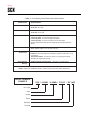
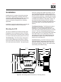
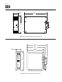
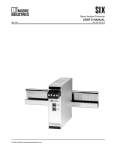
SCX
Signal Current Isolator
USER’S MANUAL
November 1991
© 1991 by Moore Industries-International, Inc.
No. 109-701-00 E
Table of Contents
Introduction
1
Description
1
Calibration
3
Installation
5
Maintenance
8
HR.
DELIVERY
8
4
UnitedStates/Canada
TOLLFREE
1-800-999-2900
United Kingdom
FREEPHONE
0800 525107
Australia
TOLLFREE
008 251928
Ask for the STAR Center
16650 Schoenborn Street
Sepulveda, California 91343, U.S.A.
Tel: (818) 894-7111 • Tlx: 65-1322
FAX: (818) 891-2816
CONNECT (MacNet): MIISEPULVEDA
1 Lloyds Court, Manor Royal, Crawley
W. Sussex RH10-2QU, United Kingdom
Tel: 0293 514488 • Tlx: 87667
FAX: 0293 536852
Moore Industries’ STAR* Center has a
wide variety of quality instrumentation
in stock and ready to ship.
• Signal Transmitters
• Temperature Transmitters
• P/I and I/P Converters
• Isolators and Converters
• Indicators and Displays
• Alarm Trips
• Integrators and Totalizers
• Power Transducers
• Instrument Power Supplies
• Racks, Rails and Enclosures
Most instruments can be customized
to meet your needs. Even then, you’ll
never have to wait more than a few days.
Moore Industries
3/18 Resolution Drive, Caringbah
New South Wales 2229, Australia
Tel: (02) 525-9177 • Tlx: 790-75914
FAX: (02) 525-7296
CENTER
* Support, Technical Assistance, and Repair (our Quick-Ship Facility)
SCX
Page 1
Introduction
Options
Moore Industries’ Signal Current Isolator (SCX) is a
process instrument that accepts a process variable
current input and provides an isolated current output.
The SCX is available with the following options:
This manual contains descriptive, calibration, and
installation information for the SCX. Notes are
presented in this manual to help you avoid minor
inconveniences while calibrating or installing this
instrument.
Description
The SCX accepts a 4-20 or 10-50 milliampere (mA)
input and outputs a proportional, isolated process
variable signal of the same value. Units with 10-50
mA inputs can be factory-configured to output 4-20
mA (not with ECD Housings). Units configured with
4-20 mA inputs have 4-20 mA outputs only. The
input and output are factory configured to user
specifications.
Power requirements for the SCX vary depending on
the combined input/output configuration of the unit.
Table 1 listed the voltage drops (requirements)
considerations for the SCX.
The SCX has no visual indicators, but does have one
adjustment; the TRIM potentiometer (pot). The TRIM
pot is located on the front panel and is used to adjust
the output signal for a precise span value.
The SCX is available in three basic housing styles;
the hockey-puck (HP), DIN-style, and economy DINstyle (ECD). Functionally they are identical. The
housing style you select should be based on the
application and the environment in which the unit is
to be used.
Table 1 contains the operational and performance
specifications of the SCX.
RF Option — RFI and EMI protection to 50 V/m –
abc -0.1% of full-scale when tested according to
SAMA standard PMC 33.1 (not available for ECD
Housings).
RTB Option — Removable terminal block for DINstyle units only.
WTD Option — Water-tight enclosure for ECD
housed units meeting NEMA 4 and SAA Type N
(IP65) requirements.
For information on availability of other SCX options,
contact your local Moore Industries’ Sales Representative.
Serial/Model Number. Moore Industries uses a
serial number-based tracking system to maintain
historical records on each individual product that we
sell or service. The model number contains important configuration information about the product to
which it corresponds. Together, the serial and model
numbers provide the factory, and the user, with
information regarding the unit’s history and functional
configuration.
If service information is required, you must provide
the factory with the unit’s serial number. Providing
the model number is also important when technical
assistance is required. The serial and model numbers for PC units is etched into a stainless steel tag
on the front of the unit. For DIN-style and ECD units,
these numbers are printed on a label and affixed to
the side of each unit.
The model number contains information about the
configuration of the unit as it was shipped from the
factory. The following model number example
identifies the significance of each field of the SCX
model number.
SCX
Page 2
Table 1. SCX Operational and Performance Specifications
Charateristic
Input
Specifications
4-20 mA, into 275ý
10-50 mA, into 150ý
Output
4-20 mA, into 0-250ý
10-50 mA, into 0-100ý
Power
Supplied as input, loop excitation:
5.5 V loop power, for 4-20 mA input and output
8.5 V loop power, for 10-50 mA input and output
4.5 V loop power, for 10-50 mA input and 4-20 mA output
(Power requirements listed are the voltage drops caused by the SCX
alone.)
Controls
Performance
Environmental
Ratings
Multiturn potentiometer, front panel
Trim: Adjusts output to ±1% of span accuracy
Accuracy: ±0.075% of span
Isolation: Input and output are transformer isolated to 500 Vrms, no dc
connections
Temperature Affect: ±0.018%/°C (±0.01%/°F) per degree change;
±0.005% per degree gain change
Ambient Operating Temperature: –29 to 82 °C (–20 to 180 °F)
NOTE: Refer to the Installation Section of this manual for the unit’s outline dimensions.
MODEL NUMBER
EXAMPLE
Unit Type
Input
Output
Power
Option(s)
Housing
SCX / 4-20MA / 4-20MA / 5.5VLP / -RF [HP]
SCX
Page 3
Calibration
Calibration Setup
Every SCX is calibrated and tested at the factory
prior to shipment. Before placing an SCX into
service, you should set it up for a bench check and
verify that it responds to known inputs in a predictable manner. A bench check will indicate if the SCX
is ready to be placed into service or if it needs to be
re-calibrated. To bench check and calibrate an SCX
properly, your must use test equipment that allows
you to vary the input and monitor the output. The
equipment and setup requirements are described in
the Calibration Setup subsection later in this section.
Since the SCX has no visual indicators, its operational performance must be verified with calibration
equipment. The equipment required to bench check
and calibrate the SCX is listed in table 2. The
accuracy of the equipment used is very important. If
uncalibrated test equipment is used, the input you
apply and output readings you observe will be
unreliable, and the actual performance of the SCX
unpredictable.
SCX Controls
The SCX has one control; the Trim pot. This potentiometer is located on the front panel (all housing
styles) and is labeled “TRIM”. This adjustment
changes the gain of the output span. This single
adjustment varies the zero- and 100-percent output
values equally so that you can adjust the signal to
have the same amount of offset at both extremes.
With the Trim adjustment you can set the 16 mA
span for 4-20 mA outputs with very high precision.
The same is true for the 40 mA span of the 10-50 mA
outputs.
Although the SCX can be calibrated in its installation
location, typically it is easier to work with the calibration equipment in a laboratory setting (e.g., a technicians workbench).
Figure 1 illustrates the hookup requirements for
bench check and calibration of the SCX. The
terminal designations for each connection are clearly
marked on the front panel of each unit. The SCX
uses four terminals; +IN and –IN for the input signal
and +OUT and –OUT for the isolated output signal.
All housing styles use a compression-screw principle
to make individual wire connections. HP and ECD
housed units provide wire access through the top
and bottom of the terminal locations with compression screws accessed at the front of the unit. For
standard DIN-style units the wire and screw access
are both on the same plane (i.e., the front surface) of
the unit.
Table 2. SCX Calibration Equipment
Equipment
Adjustable Current
Source
Voltmeter & Load
Resistor
Milliammeter
Screwdriver
Characteristics
Capable of simulating specified input range (4-20 or 10-50 mA)
and voltage requirements (see table 1)
Voltmeter, accuracy of 0.05% or better; Load resistor, 250ý for 420 mA output, 100ý for 10-50 mA output, tolerance of ±0.02%
Accuracy of 0.05% or better
Slotted-tip, head width no greater than 2.54 mm (0.1 inch)
SCX
Page 4
MILLIAMMETER
+
–
+
+OUT
ADJUSTABLE
CURRENT
SOURCE
+
+IN
DC
VOLTMETER
SCX
–
–IN
–
–OUT
(SEE NOTE 2)
(SEE NOTE 1)
NOTES:
1. Check unit's model number for input and output configuration.
2. For a 1-5 Vdc reading, use a 250 resistor for 4-20 mA
outputs or a 100 resistor for 10-50 mA output.
Figure 1. SCX Calibration Hookup
Calibration Procedure
Before beginning this procedure, check the model
number of the unit to be calibrated to verify the
power requirement of the unit and what the input and
output are configured for. The following procedure is
suitable for all SCX’s.
Refer to table 2 for a list of calibration equipment and
use figure 1 for hookup requirements.
1. Connect SCX and calibration equipment as
shown in figure 1.
2. Apply power and allow SCX to warm-up for 5
minutes.
3. Set adjustable input source for median input
based on input configuration (12 mA for 4-20 mA
input; 30 mA for 10-50 mA input).
4. Monitor output with voltmeter to verify proportional output reading is present (3 Vdc).
NOTE
If your unit is configured for 10-50 mA
input and 4-20 mA output, an input of 30
mA should produce an output reading 12
mA (3 Vdc).
5. Adjust TRIM pot, as required, to bring the
median output reading to match the (appropriate)
median input.
6. Set adjustable input source for zero-percent
input as stated in model number.
7. Verify zero-percent output (1 Vdc, ±3 mV)
corresponds to zero-percent input.
8. Set adjustable input source for 100-percent input
as stated in model number.
9. Verify 100-percent output (5 Vdc, ±3 mV) corresponds to 100-percent input.
10. If zero- or 100-percent output reading do not
correspond to appropriate inputs, repeats steps 3
through 9.
11. When output readings are stable and consistent,
remove power and disconnect calibration equipment. Calibration is complete.
If you have difficulty performing the calibration
procedure, contact Moore Industries’ Customer
Service Department for assistance.
SCX
Page 5
Installation
ends of the spring clips toward one another, the unit
can be positioned in the base. When released, the
spring clips apply adequate outward pressure to hold
the HP unit in the enclosure. If the basic HP Housing
is equipped with flange plates (FL Housing), it can be
mounted on flat surfaces or relay tracks. Figure 2 is
an outline dimension drawing of the HP Housing.
The spring clips have no dimensional significance so
they are not shown, but the flange plates do (see
figure 2).
Installing the SCX consists of physically mounting
the unit and completing the necessary electrical
connections. Before installing the SCX, you should
check its model number and bench check it to
ensure it is properly configured for the intended
application.
Installation is generally made easier by mounting the
unit before making the electrical connections.
The DIN-style Housing. The DIN-style Housing is
designed to mount directly on standard G-type
(EN50035) or Top-hat (EN50022) DIN rails. At the
rear of this unit are the lips and grooves for mounting
on a rail. This unit is mounted by positioning it so
that the upper portion of the DIN-rail mating elements
hook either under or over (depending on the rail
type) the top of the rail, then, rotate the front of the
unit downward. Figure 3 is an outline dimension
drawing of the DIN-style SCX.
Mounting the SCX
The SCX is available in three basic housing styles.
Regardless of the housing style chosen, mounting
the SCX in an area free of excessive dust, moisture,
or corrosive elements will prolong the life of the unit.
The HP Housing. The HP Housing is designed to
mount inside explosion-proof enclosures. Spring
clips on the basic HP Housing are used to hold the
unit in the base of the enclosure. By squeezing the
The ECD Housing. The ECD Housing is a plastic
DIN-style housing. This housing mounts on the Gtype and Top-hat DIN rails in the same manner as
the DIN-style Housing. Figure 4 is an outline dimension drawing of the ECD Housing.
49 mm
(1.92 in)
75.4 mm
(2.97 in)
62.2 mm
(2.45 in)
38 mm
(1.50 in)
55 mm
(2.17 in)
SC
SIGNAL
CURRENT ISOLATOR
72.6 mm
(2.86 in)
82.5 mm
(3.25 in)
GND
61 mm
(2.40 in)
+IN
–IN
1
3
2
+OUT
µ
5
4
6
TRIM
–OUT
MOORE INDUS
Figure 2. HP Housing Outline Dimensions (FL Housing shown)
SCX
Page 6
25.4mm
(1 in)
+IN
–IN
+OUT
107 mm
(4.2 in)
–OUT
SC
80 mm
(3.15 in)
TRIM
–T
µ
+T
MOORE INDUSTRIES
Figure 3. DIN-style Housing Outline Dimensions
90.17 mm
(3.55 in)
85 mm
(3.35 in)
23 mm
(.91 in)
74 mm
(2.90in)
+
–
IN
IN
SC
SIGNAL
CURRENT
ISOLATOR
79 mm
(3.10 in)
TRIM
™
+
–
OUT
OUT
Figure 4. ECD Housing Outline Dimensions
SCX
Page 7
Making the Electrical Connections
tion of the unit. When preparing to place the SCX
into service, it is important for you to know the
voltage available in the process, and what the
voltage drop is of the SCX. You must also factor in
the voltage drop of the device the SCX outputs to.
Refer to table 1 for the power requirements of the
SCX.
The electrical connections for the SCX are made to
individual, compression-screw terminals. The +IN
and –IN terminals are for the input signal. The +OUT
and –OUT terminals are for the isolated output
signal. Each of these terminals is clearly marked on
the unit.
Figure 5 is a typical hookup diagram for the SCX
when it is used to isolate a 2-wire process loop
signal. Figure 6 is a typical hookup for isolating
signal from a 4-wire instrument.
The ends of each termination wire should be striped
appropriately 6.25 mm (0.25 inch) to expose bare
conductor wire. If “stranded” signal wire is used, DO
NOT apply solder to the termination area. For lowlevel signals, we recommend shielded, twisted-pair
wire. When shielded wire is used, ground the shield
as near to the unit as possible, but NOT to its case.
DIN Unit Test Points. The DIN-style Housing has
two test points, marked “+T” and “–T”, on the front
panel. These test points can be used to monitored
the units output without affecting the process loop.
To use these test points, connect a dc voltmeter
across them and convert the meter reading using this
equation: 0.1 Vdc = 10 mA.
The 4-20 or 10-50 mA input signal comes from a
process operation. The power requirements for the
SCX differ depending on the input/output configura-
+OUT
–IN
+OUT
2-WIRE
TRANSMITTER
+
SCX
–OUT
+IN
–OUT
–
CURRENT
DRIVEN
DEVICE
(SEE NOTE )
–
+
DC POWER
SOURCE
NOTE:
Check model number for unit's input and output
configuration and power requirements.
Figure 5. Typical Installation Hookup for a 2-wire Loop Input
SCX
Page 8
+IN
+OUT
INPUT
SIGNAL
+OUT
+IN
4-WIRE
TRANSMITTER
–IN
+
–
+
–
+
SCX
–OUT
AC OR DC
POWER
SOURCE
–IN
–OUT
–
CURRENT
DRIVEN
DEVICE
(SEE NOTE)
NOTE:
Check model number for unit's input and output
configuration and power requirements.
Figure 6. Typical Installation Hookup Using a 4-wire Input Device
Maintenance
Once the SCX is properly calibrated and installed, it
will operate reliably for extended periods of time.
Routine maintenance of the SCX is limited to keeping the unit clean and ensuring terminal connections
are secure and free of oxidation. We recommend
that you visually inspect the unit at least once every
six months to ensure its physical condition is acceptable.
Periodically, you may wish to check the performance
of the SCX to ensure that it is operating within the
desired parameters. To check its operational
performance, take the unit off line and set it up for a
bench check as described in the Calibration Section
of this manual. Perform the calibration procedures
contained therein to verify the operating condition of
the unit.
The schedule for in-service bench checks depends
on your facility’s maintenance practices and on the
unit’s performance. We recommend that you bench
check the SCX approximately once a year. But, if
there is no indication of variation in performance, you
may elect to let the SCX remain on-line for longer
periods.
If an operational problem arises with the SCX,
contact Moore Industries’ Customer Service Department at 1-800-999-2900 or your local Sales Representative for assistance. To return a unit, follow the
instructions on the back cover of this manual.
Declaration of Conformity
EMC Directive 89/336/EEC
Manufacturer’s Name:
Manufacturer’s Address:
Moore Industries-International, Inc.
16650 Schoenborn Street
North Hills, CA 91343-6196
USA
Declares that the product(s):
Product Name:
SCX
MODEL
Model Number(s):
SCX
SCX
/
INPUT
*
*
/
OUTPUT
/
*
*
POWER
*
*
/
OPTIONS
*-CE1
*-CE
/ HOUSING
HP
DIN, ECD
*Indicates any input, output power and option as stated on the product data sheet.
Conforms to the following EMC specifications:
EN50081-2, 1993, Generic Emissions Standard, Industrial Environment.
EN50082-2, 1995, Generic Immunity Standard, Industrial Environment.
Supplemental Information:
1
RF filters are required for the CE Option.
Janurary 22, 1999
Date
______________________________
Fred Adt
Quality Assurance Director
_____________________________________
Robert Stockham
Moore Industries-International, Inc.
European Contact: Your Local Moore Industries Sales and Service Office
RETURN PROCEDURES
To return equipment to Moore Industries for repair, follow these four steps:
1. Call Moore Industries and request a Returned Material Authorization (RMA) number.
Warranty Repair –
If you are unsure if your unit is still under warranty, we can use the unit’s serial number
to verify the warranty status for you over the phone. Be sure to include the RMA
number on all documentation.
Non-Warranty Repair –
If your unit is out of warranty, be prepared to give us a Purchase Order number when
you call. In most cases, we will be able to quote you the repair costs at that time.
The repair price you are quoted will be a “Not To Exceed” price, which means that the
actual repair costs may be less than the quote. Be sure to include the RMA number on
all documentation.
2. Provide us with the following documentation:
a) A note listing the symptoms that indicate the unit needs repair
b) Complete shipping information for return of the equipment after repair
c) The name and phone number of the person to contact if questions arise at the factory
3. Use sufficient packing material and carefully pack the equipment in a sturdy shipping
container.
4. Ship the equipment to the Moore Industries location nearest you.
The returned equipment will be inspected and tested at the factory. A Moore Industries
representative will contact the person designated on your documentation if more information is
needed. The repaired equipment, or its replacement, will be returned to you in accordance with
the shipping instructions furnished in your documentation.
WARRANTY DISCLAIMER
THE COMPANY MAKES NO EXPRESS, IMPLIED OR STATUTORY WARRANTIES (INCLUDING ANY WARRANTY OF MERCHANTABILITY OR OF FITNESS
FOR A PARTICULAR PURPOSE) WITH RESPECT TO ANY GOODS OR SERVICES SOLD BY THE COMPANY. THE COMPANY DISCLAIMS ALL WARRANTIES ARISING FROM ANY COURSE OF DEALING OR TRADE USAGE, AND
ANY BUYER OF GOODS OR SERVICES FROM THE COMPANY ACKNOWLEDGES THAT THERE ARE NO WARRANTIES IMPLIED BY CUSTOM OR
USAGE IN THE TRADE OF THE BUYER AND OF THE COMPANY, AND THAT
ANY PRIOR DEALINGS OF THE BUYER WITH THE COMPANY DO NOT IMPLY THAT THE COMPANY WARRANTS THE GOODS OR SERVICES IN ANY
WAY.
ANY BUYER OF GOODS OR SERVICES FROM THE COMPANY AGREES
WITH THE COMPANY THAT THE SOLE AND EXCLUSIVE REMEDIES FOR
BREACH OF ANY WARRANTY CONCERNING THE GOODS OR SERVICES
SHALL BE FOR THE COMPANY, AT ITS OPTION, TO REPAIR OR REPLACE
THE GOODS OR SERVICES OR REFUND THE PURCHASE PRICE. THE
COMPANY SHALL IN NO EVENT BE LIABLE FOR ANY CONSEQUENTIAL OR
INCIDENTAL DAMAGES EVEN IF THE COMPANY FAILS IN ANY ATTEMPT
TO REMEDY DEFECTS IN THE GOODS OR SERVICES , BUT IN SUCH CASE
THE BUYER SHALL BE ENTITLED TO NO MORE THAN A REFUND OF ALL
MONIES PAID TO THE COMPANY BY THE BUYER FOR PURCHASE OF THE
GOODS OR SERVICES.
United States • [email protected]
Tel: (818) 894-7111 • FAX: (818) 891-2816
Australia • [email protected]
Tel: (02) 8536-7200 • FAX: (02) 9525-7296
© 2007 Moore Industries-International, Inc.
ANY CAUSE OF ACTION FOR BREACH OF ANY WARRANTY BY THE
COMPANY SHALL BE BARRED UNLESS THE COMPANY RECEIVES
FROM THE BUYER A WRITTEN NOTICE OF THE ALLEGED DEFECT OR
BREACH WITHIN TEN DAYS FROM THE EARLIEST DATE ON WHICH THE
BUYER COULD REASONABLY HAVE DISCOVERED THE ALLEGED DEFECT OR BREACH, AND NO ACTION FOR THE BREACH OF ANY WARRANTY SHALL BE COMMENCED BY THE BUYER ANY LATER THAN
TWELVE MONTHS FROM THE EARLIEST DATE ON WHICH THE BUYER
COULD REASONABLY HAVE DISCOVERED THE ALLEGED DEFECT OR
BREACH.
RETURN POLICY
For a period of thirty-six (36) months from the date of shipment, and under
normal conditions of use and service, Moore Industries ("The Company") will
at its option replace, repair or refund the purchase price for any of its manufactured products found, upon return to the Company (transportation charges
prepaid and otherwise in accordance with the return procedures established
by The Company), to be defective in material or workmanship. This policy
extends to the original Buyer only and not to Buyer's customers or the users
of Buyer's products, unless Buyer is an engineering contractor in which case
the policy shall extend to Buyer's immediate customer only. This policy shall
not apply if the product has been subject to alteration, misuse, accident, neglect or improper application, installation, or operation. THE COMPANY
SHALL IN NO EVENT BE LIABLE FOR ANY INCIDENTAL OR CONSEQUENTIAL DAMAGES.
Belgium • [email protected]
Tel: 03/448.10.18 • FAX: 03/440.17.97
The Netherlands • [email protected]
Tel: (0)344-617971 • FAX: (0)344-615920
China • [email protected]
Tel: 86-21-62491499 • FAX: 86-21-62490635
United Kingdom • [email protected]
Tel: 01293 514488 • FAX: 01293 536852
Specifications and Information subject to change without notice.


![ECT[DIN] [DIN] - Moore Industries International](http://vs1.manualzilla.com/store/data/005778735_1-93255c4f7d497ff32afcfe496e72d982-150x150.png)