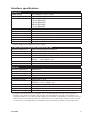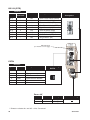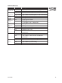
1
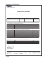
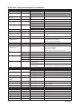
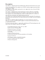
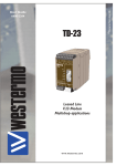
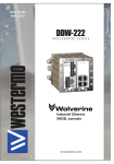
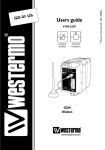
TDW-33
6619-2201
DIN-rail
Tele V.90 modem
www.westermo.com
© Westermo Teleindustri AB • 2006
User Guide
Legal information
The contents of this document are provided “as is”. Except as required by applicable
law, no warranties of any kind, either express or implied, including, but not limited to,
the implied warranties of merchantability and fitness for a particular purpose, are made
in relation to the accuracy and reliability or contents of this document. Westermo
reserves the right to revise this document or withdraw it at any time without prior
notice.
Under no circumstances shall Westermo be responsible for any loss of data or income
or any special, incidental, and consequential or indirect damages howsoever caused.
More information about Westermo can be found at the following Internet address:
http://www.westermo.com
2
6619-2201
Safety
Before installation:
This modem is for restricted access area use only.
Read this manual completely and gather all information on the unit. Make sure
that you understand it fully. Check that your application does not exceed the safe
operating specifications for this unit.
This unit should only be installed by qualified personnel.
This unit should be built-in to an apparatus cabinet, or similar, where access is
restricted to service personnel only.
The power supply wiring must be sufficiently fused, and if necessary it must be
possible to disconnect manually from the power supply. Ensure compliance to
national installation regulations.
This unit uses convection cooling. To avoid obstructing the airflow around the unit,
follow the spacing recommendations (see Cooling section).
Before mounting, using or removing this unit:
Prevent access to hazardous voltage by disconnecting the unit from power supply.
Warning! Do not open connected unit. Hazardous voltage may occur within this
unit when connected to power supply or TNV circuits.
Care recommendations
Follow the care recommendations below to maintain full operation of unit and to fulfil
the warranty obligations.
This unit must not be operating with removed covers or lids.
Do not attempt to disassemble the unit. There are no user serviceable parts inside.
Do not drop, knock or shake the unit, rough handling above the specification may cause
damage to internal circuit boards.
Do not use harsh chemicals, cleaning solvents or strong detergents to clean the unit.
Do not paint the unit. Paint can clog the unit and prevent proper operation.
Do not expose the unit to any kind of liquids (rain, beverages, etc). The unit is not waterproof. Keep the unit within the specified humidity levels.
Do not use or store the unit in dusty, dirty areas, connectors as well as other mechanical
part may be damaged.
If the unit is not working properly, contact the place of purchase, nearest Westermo
distributor office or Westermo Tech support.
Maintenance
No maintenance is required, as long as the unit is used as intended within the specified
conditions.
The unit interior doesn’t contain any user settable items, all configuration is performed
via the DTE interface with AT-commands.
6619-2201
3
Agency approvals and standards compliance
Type
Approval / Compliance
EMC
EN 61000-6-2, Immunity industrial environm
EN 55024, Immunity IT equipment
EN 61000-6-3, Emission residential environments
FCC part 15 Class B
EN 50121-4, Railway signalling and telecommunications apparatus
IEC 62236-4, Railway signalling and telecommunications apparatus
Safety
EN 60950-1, IT equipment
PSTN
ETSI TS103 021-1, ETSI TS103 021-2, ETSI TS103 021-3
FCC Part 15.105 Notice:
4
This equipment has been tested and found to comply with the
limits for a Class B digital device, pursuant to Part 15 of the
FCC Rules. These limits are designed to provide reasonable protection against harmful interference in a residential installation.
This equipment generates, uses and can radiate radio frequency
energy and, if not installed and used in accordance with the
instructions, may cause harmful interference to radio communications. However, there is no guarantee that interference will not
occur in a particular installation. If this equipment does cause
harmful interference to radio or television reception, which can
be determined by turning the equipment off and on, the user is
encouraged to try to correct the interference by one or more of
the following measures:
… Reorient or relocate the receiving antenna
… Increase the separation between the equipment and receiver
… Connect the equipment into an outlet on a circuit different
from that to which the receiver is connected
… Consult the dealer or an experienced radio/TV technician
for help.
6619-2201
Declaration of Conformity
Westermo Teleindustri AB
Declaration of conformity
The manufacturer
Westermo Teleindustri AB
SE-640 40 Stora Sundby, Sweden
Herewith declares that the product(s)
Type of product
Model
DIN-rail Tele and Leased Line
modem
TDW-33
Art no
3619-0001
Installation manual
6619-2201
is in conformity with the following EC directive(s).
No
Short name
89/336/EEG
73/23/EEG
Electromagnetic Compatibility (EMC)
Low Voltage Directive - LVD
References of standards applied for this EC declaration of conformity.
No
Title
Issue
EN 61000-6-2
EN 55024
EN 61000-6-3
EN 60950
EN 50121-4
IEC 62236-4
Immunity for industrial environments
Information technology equipment – Immunity
Emission standard for industrial environments
Safety of information technology equipment
Railway signalling and telecommunications apparatus
Railway signalling and telecommunications apparatus
2 (2001)
1 (1998)
1 (2001)
6 (2000)
The last two digits of the year in which the CE marking was affixed:
06
Herewith declares that product(s) listed above is in conformity with
No
FCC part 15
Title
Issue
Radio frequency devices
Hans Levin
Technical Manager
03th October 2006
Postadress/Postal address
Tel.
Telefax
Postgiro
Bankgiro
Org.nr/
Corp. identity number
Registered office
S-640 40 Stora Sundby
016-428000
016-428001
52 72 79-4
5671-5550
556361-2604
Eskilstuna
Sweden
Int+46 16428000
Int+46 16428001
6619-2201
5
Type tests and environmental conditions
Electromagnetic Compatibility
Phenomena
Test
ESD
EN 61000-4-2
Test levels
± 6 kV
± 8 kV
20 V/m 80% AM (1 kHz), 80 – 2000 MHz
20 V/m pulse modulated 200 Hz, 900 ± 5 MHz
± 2 kV
± 2 kV
± 2 kV line to earth, ± 2 kV line to line
± 2 kV line to earth, ± 1 kV line to line
± 2 kV line to earth, ± 2 kV line to line
10 V 80% AM (1 kHz), 0.15 – 80 MHz
10 V 80% AM (1 kHz), 0.15 – 80 MHz
100 A/m, 50 Hz, 16.7 Hz & 0 Hz
300 A/m, 6.4 / 16 μs pulse
10 & 5 000 ms, interruption
10 & 500 ms, 30% reduction
100 & 1 000 ms, 60% reduction
100 V 50 Hz line to earth
250 V 50 Hz line to line
10 & 100 ms, interruption
10 ms, 30% reduction
10 ms, 60% reduction
+20% above & –20% below rated voltage
Class B
Class B
Class B
Class B
Class B
2 kVrms 50 Hz 1 min
RF field AM
modulated
RF field 900 MHz
Fast transient
IEC 61000-4-3
Surge
EN 61000-4-5
RF conducted
EN 61000-4-6
Power frequency
magnetic field
Pulse magnetic field
Voltage dips
and interruption
EN 61000-4-8
Enclosure
Signal ports
Power ports
Signal ports unbalanced
Signal ports balanced
Power ports
Signal ports
Power ports
Enclosure
EN 61000-4-9
EN 61000-4-11
Enclosure
AC power ports
Mains freq. 50 Hz
Mains freq. 50 Hz
Voltage dips
and interruption
EN 61000-4-16
SS 436 15 03
EN 61000-4-29
Signal ports
Signal ports
DC power ports
Radiated emission
EN 55022
FCC part 15
EN 55022
FCC part 15
EN 55022
EN 60950
Enclosure
Conducted emission
Dielectric strength
Environmental
Temperature
Humidity
ENV 50204
EN 61000-4-4
AC power ports
AC power ports
DC power ports
Signal port to other
isolated ports
Power port to other
isolated ports
Operating
Storage & Transport
Operating
Storage & Transport
Operating
MIL-HDBK- 217F Operating
Altitude
Reliability prediction
(MTBF)
Service life
Vibration
IEC 60068-2-6
Operating
Operating
Shock
IEC 60068-2-27
Operating
Packaging
Enclosure
UL 94
Dimension W x H x D
Weight
Degree of protection IEC 529
Cooling
Mounting
6
Description
Enclosure contact
Enclosure air
Enclosure
PC / ABS
Enclosure
3 kVrms 50 Hz 1 min
2 kVrms 50 Hz 1 min (@ rated power <60 V)
–25 to +70°C
–40 to +70°C
5 to 95% relative humidity non condensing
5 to 95% relative humidity non condensing
2 000 m / 70 kPa
10 year
7.5 mm, 5 – 8 Hz
2 g, 8 – 500 Hz
15 g, 11 ms
Flammability class V-1
35 x 121 x 119 mm
0.21 kg
IP 21
Convection
Horizontal on 35 mm DIN-rail
6619-2201
Description
The TDW-33 is designed to function reliably within industrial environments and in areas
of high level interference. The modem has an RS-232 interface supporting terminal data
rates up to 115 kbit/s.
The TDW-33 is a V.90 modem meaning that it can support data rates of up to 56 kbit/s
on the PSTN line side.
The modem is equipped with transient protection on the line side and a “watchdog”
that monitors and automatically resets the modem in the event of a fault. These functions together with remote configuration make the modem perfect for installation at
unmanned sites and prevent the need of costly service trips.
The modem also has password protection, dial-back security and caller ID answering to
ensure that only authorised users can communicate with the modem and any connected
equipment.
The TDW-33 is ideal for industrial applications as it mounts easily on to a 35 mm
DIN-rail, runs from 12–36 VDC power supplies, has screw terminal connections and
is tri galvanically isolated.
For ease of setup the modem is supported by the Westermo TD-tool configuration software. Drivers for Windows setup are also supplied.
… Extended temperature range –25°C to +70°C
… Data rate up to 56 kbit/s (V.90)
… Terminal rate up to 115.2 kbit/s
… DTR and incoming data dialling
… Watchdog
… Secure call back and access
… Industrial environment transient protection on all interfaces
… Up to 11 data bits
… Tri-Galvanic isolation (interface/line/supply)
… Caller ID presentation and answering
… Remote configuration
6619-2201
7
Remote configuration
The TDW-33 can be configured from a remote modem. To configure a TDW-33 any GSM,
ISDN or PSTN modem can be used.
The modem used to configure is referred as the “local modem”. To enable remote configuration use the command AT*WRAA.
Please make sure that the remote TDW-33 is connected to the PSTN network and is
powered up.
…
…
…
…
…
Connect the local modem to it’s media (ISDN, PSTN or GSM).
Connect the PC’s com-port to the DTE interface of the local modem.
Connect the power supply.
Start a terminal emulation program (i.e. Windows Hyper-Terminal).
Configure the local modem data rate and word format.
1. If the local modem is a GDW-11/12 a normal GSM data connection should be
used.
2. If the local connection is ISDN, configure with the B channel protocol as V110
9600 bit/s
3. If the local connection uses some analogue modem , the modem has to be configured for V32 modulation and a line speed of 9600 bit/s.
… Set up a connection to the remote TDW-33 to be configured by using the normal dial command: ATD<No><CR>. When connected send the remote escape
sequence <++++>. The called remote TDW-33 will acknowledges by requesting
the remote password. Enter the correct password (default: no password, just
return). Next configure the remote TDW-33 using AT-commands. The password
for remote configuration is defined with AT*WRAP – Remote access password
… Configure the parameter on the remote TDW-33 from your terminal program
and save the settings with AT&W.
… Hang up the connection using the ATH command.
8
6619-2201
Interface specifications
Power LV
Rated voltage
Operating voltage
Rated current
Rated frequency
Inrush current I2t
Startup current*
Polarity
Isolation to
Connection
Connector size
Shielded cable
12 to 48 VDC or 12 to 27 VAC
10 to 60 VDC or 10 to 30 VAC
150 mA @ 12 VDC
70 mA @ 24 VDC
40 mA @ 48 VDC
150 mA @ 12 VAC
70 mA @ 24 VAC
DC / AC 48 – 62 Hz
0.25 A2s
0.30 Apeak
Polarity independent
All other ports 3 kVrms 50 Hz 1 min
Detachable screw terminal
0.2 – 2.5 mm2 (AWG 24-12)
Not required
* External supply current capability for proper startup.
Public Switched Telephone Network (PSTN)
Electrical specification
Data rate
Protocol
Protection
Isolation to
Connection
Shielded cable
Public Switched Telephone Network
300 bit/s – 33.6 kbit/s
Bell103, Bell212, V.21, V.22, V.22Bis, V.23C, V.32, V.32Bis, V.34, V.90
Installation Fault Tolerant (up to ±60 V)
Power port 3 kVrms 50 Hz 1 min
RS-232
2 kVrms 50 Hz 1 min
RJ-11C
Not required
RS-232
Electrical specification
Data rate
Data format
Protocol
Retiming
Transmission range
Isolation to
Connection
Connector size
Shielded cable
Conductive housing
EIA/TIA-232
1 200 bit/s – 115.2 kbit/s
7 or 8 data bits, Odd, even or none parity, 1 or 2 stop bits; Σ 9-12 bits
Transparent
Yes
Cable length < 15 m
Power port 3 kVrms 50 Hz 1 min
PSTN line 2 kVrms 50 Hz 1 min
9-pin D-sub female (DCE) and Detachable screw terminal (DCE )
Detachable screw terminal 0.2 – 2.5 mm2 (AWG 24 – 12)
Not required *
Isolated to all other circuits
* To minimise the risk of interference, a shielded cable is recommended when the cable is located inside 3 m
boundary to the rails and connected to this port. The cable shield should be properly connected (360°) to an
earthing point within 1 m from this port. This earthing point should have a low impedance connection to the conductive enclosure of the apparatus cabinet, or similar, where the unit is built-in. This conductive enclosure should
be connected to the earthing system of an installation and may be directly connected to the protective earth.
6619-2201
9
RS-232 (DTE)
Position
D-sub
Screw
terminal*
No. 1
–
No. 2
2
No. 3
1
No. 4
3
No. 5
5
No. 6
4
No. 7
–
No. 8
–
No. 9
–
Direction*
NC
Out
In
In
NC
Out
NC
NC
NC
Description
D-sub
description
Data Carrier Direct (DCD)
Received Data (RD)
Transmitted Data (TD)
Data Terminal Ready (DTR)
Signal Ground (SG)
Data Set Ready (DSR)
Request To Send (RTS)
Clear To Send (CTS)
Ring Indicator (RI)
1
2
3
4
5
6
7
8
9
LED Indicators
(for details see next page)
PSTN
Position
RJ-11C Direction* Description
a
b
c
d
e
f
In/Out
In/Out
Product marking
PSTN
NC
NC
PSTN Transmit/ Receive
PSTN Transmit/ Receive
NC
NC
Power LV
Position Direction*
No. 1
In
No. 2
In
Description
–Voltage
+Voltage
Product marking
* Direction relative this unit. NC = Not Connected
10
6619-2201
LED Indicators
LED
TD
Transmit data
RD
Receive data
RTS
Request
to send
DCD
Data carrier
detect
DTR
Data carrier
detect
REL
Reliable mode
LINE
PWR
Power
6619-2201
Status
OFF
ON / FLASH
OFF
ON / FLASH
OFF
ON
OFF
ON
OFF
ON
OFF
ON
FLASH
OFF
ON
FLASH
OFF
ON
FLASH
Description
No data
The modem receiving data on the DTE interface
No data
The modem transmitting data on the DTE interface
RTS signal is inactive
RTS signal is active
DCD signal is inactive
DCD signal is active, modem has detected a carrier
or the signal is set to always ON
DTR signal is inactive
DTR signal is active
Reliable mode is OFF, direct or normal mode
Reliable mode is ON
Reliable mode with error correction and
compression
The modem is on-hook
The modem is off-hook with a established
connection
The modem is off-hook and negotiating
The modem has no power
The modem is up and running
The modem is in the power-on selftest
11
Mounting
This unit should be mounted on 35 mm DIN-rail, which is
horizontally mounted inside an apparatus cabinet, or similar.
Snap on mounting, see figure.
CLICK!
Cooling
This unit uses convection cooling. To avoid obstructing the airflow around the unit, use the following spacing rules. Minimum
spacing 25 mm (1.0 inch) above /below and 10 mm (0.4 inches)
left /right the unit. Spacing is recommended for the use of unit
in full operating temperature range and service life.
10 mm *
(0.4 inches)
25 mm
* Spacing (left/right) recommended for
full operating temperature range
25 mm
Removal
Press down the black support at the top of the unit. See figure.
12
6619-2201
Windows configuration tool TD-Tool
The TD-Tool is a PC – application program with a graphical interface for easy
configuration of the complex functions found in the TDW-33.
Please refer to TD-Tool for a complete description of the functionality of the
Windows program.
Configuration
The TDW-33 can be configured both from the local DTE interface and remotely over the
PSTN network. Independently if the local or remote interface is used the configuration
can be made with AT-commands or with a PC-based application configuration tool. Basic
configurations can also be made with DIPswitches locally
AT-Commands
The most commonly used commands are listed below in short format.
Please refer to the document “TDW-33 and TD-36 AT-Command Guide” for a complete
list of all the available AT-commands and a detailed description of the serial AT-command
interface.
A – Answer a call
Syntax:
ATA
&An – Dial Abort Option
Syntax:
AT&A<n>
Parameters:
<n>
0:
Enables Abort (Default)
1:
Disable Abort
&B – DTR Dial Option
Syntax:
&B<n>
Parameters:
<n>
0: Disable DTR/TX Hotcall ( Default )
1: Enable DTR Hotcall
2: Enable TX Hotcall (buffered data)
6619-2201
13
&C –DCD Option
Syntax:
AT&C<n>
Parameters:
<n>
0:
DCD remains ON at all times
1:
DCD follows the state of a carrier
D and DL – Dial command
Syntax:
ATD<nb> where <nb> represents a dial string composed of dial characters and dial
modifiers.
&D – DTR Control
Syntax:
AT&D<n>
Parameters:
<n>
0:
The DTR signal is ignored (Default)
1:
Modem switches from data to command mode when DTR switches
from ON to OFF
2:
Upon DTR switch from ON to OFF, the call is hang up
3:
DTR drop causes the modem to perfom a soft reset.
E – Echo
Syntax:
ATE<n>
Parameters:
<n>
0:
Characters are not echoed
1:
Characters are echoed
&F – Restore Factory Configuration
Syntax:
AT&F<n>
Parameters:
<n>
0:
Restore factory configuration 0
1:
Restore factory configuration 1
14
6619-2201
H – Disconnect ( Hang-Up )
Syntax:
ATH<n>
Parameters:
<n>
0:
The modem will release the line if the modem currently is on-line.
1:
If on-hook, the modem will go off-hook and enter command mode.
+ICF – Fixed DTE format
Syntax:
AT+ICF=<format>
AT+ICF=?
AT+ICF?
Parameters:
<format>:
0
Auto
4,4
7N2
5,1
7E1
5,0
7O1
3,4
8N1
2,1
8E1
2,0
8O1
4,1
7E2
4,2
7O2
1,4
8N2
1,1
8E2
1,2
8O2
6619-2201
15
+IPR – Fixed DTE rate
Syntax:
AT+IPR=<rate>
AT+IPR=?
AT+IPR?
Parameters:
<rate>: baud rates that can be used by the DCE
0
(enables autobauding)
300
600
1200
2400
4800
9600
19200
38400
57600
115200
&K – DTE-DCE flow control
Syntax:
AT&K<n>
Parameters:
<n>
0
Disables Flow Control ( Default )
3:
Enables RTS/CTS
4:
Enables XON/XOFF
5:
Enables transparent XON/XOFF
16
6619-2201
M – Speaker Control
Syntax:
ATM<n>
Parameters:
<n>
0:
Speaker OFF
1:
Speaker is on during call estabilishment, but OFF when receiving a carrier.
(Default)
2:
Speaker is always ON
3:
Speaker is off when receiving a carrier and during dialing, but on during
answering.
+MS – Select Modulation
Syntax:
+MS=<carrier>,<automode>,<min_tx_rate>,<max_tx_rate>,<min_rx_rate>,<max_rx_rate>
+MS= ?
+MS ?
Parameters:
<carrier>
V21
300 bit/s
V22
1200 bit/s
V22B
1200 or 2400 bit/s
V23C
1200/75, 75/1200 bit/s PSTN-mode dialled connections
V23HDX 1200/1200 bit/s half duplex PSTN
V32
4800 or 9600 bit/s
V32B
4800, 7200, 9600, 12000 or 14400 bit/s
V34
2400,4800,7200,9600,12000,14400,16800,19200,21600,24000,26400,28800,
31200, 33600, 33600 bit/s
V90A
up to tx=33600, rx= 56000 bit/s (client mode)
V90D
up to tx=56000, rx=33600 bit/s (server mode)
B103
300 bit/s
B212
1200 bit/s
<automode>
0:
Disable
1:
Enable
< min_xx_rate >, < max_xx_rate >
Minimum and maximum data rate depending on modulation used.
6619-2201
17
\N – Select Operating mode
Syntax:
AT\N<n>
Parameters:
<n>
0:
Selects normal speed buffered mode
1:
Selects DIRECT mode
2:
Selects reliable mode. The modem will attempt a LAPM connection and then
an MNP connection. Failure to make a reliable connection results the modem
hanging up.
3:
Selects reliable mode. Failure to make a reliable connection results the modem
falling back to speed buffered mode.
4:
Selects LAPM error-correction mode. Failure to an LAPM error-correction
connection results the modem hanging up.
5:
Selects MNP error-correction mode. Failure to an MNP error-correction connection results in the modem hanging up.
Q – Result Code Control
Syntax:
ATQ<n>
Parameters:
<n>
0:
DCE transmits result codes
1:
Result codes are suppressed and not transmitted
S0 – Automatic answer
Syntax:
ATS0=<value>
Parameters:
<value>
0-255 rings to answer on
18
6619-2201
V – Result format
Syntax:
ATV<n>
Parameters:
<n>
0
(Information responses):
0
(Result codes):
1
(Information responses):
1
(Result codes):
<text><CR><LF>
<numeric code><CR>
<CR><LF><text><CR><LF>
<CR><LF><verbose code><CR><LF>
W – Connect message control
Syntax:
ATW<n>
Parameters:
<n>
0:
Upon connection, the modem reports only the DTE speed.
1:
Upon connection, the modem reports the line speed, the error correction
protocol, and the DTE speed respectively.
2:
Upon connection, the modem reports the DCE speed
&W – Store system setting
Syntax:
AT&W<n>
Parameters:
<n>
0:
Store the current configuration as profile 0
1:
Store the current configuration as profile 1
6619-2201
19
Application examples
… TDW-33 connected to TDW-33 with DTR signal call
PSTN
Network
Configure the units
AT&F
AT&W
Set the unit to factory default
Store default settings
Set up the connection – The dialling modem
AT&Z0=nnn
AT&S0
AT&B1
AT&W
Switch DTR from
OFF to ON
Store the number of the remote modem in the dialling TDW-33
Set DSR signal always high (if this signal is used to trig the DTR)
Activates automatic DTR dialling if DTR switches from low (OFF)
to high (ON).
Save settings
The modem will now dial the phone number stored in the first location
of the AND phonebook.
Set up the connection – The answering modem
ATA
Enter the answer command when RING comes from the network or
set up ATS0=1 to auto answer on 1 RING signal (or more than 1).
NOTE: If no valid DTR signal can be provided by external application, the modems DSR signal can
be used to trig the transmission. Connect the DSR signal via a relay, or other potential
free contact, to the DTR signal. A 10 kohm pull down resistor should also be connected
between the DTR and a signal that is always low e.g. the DCD can be used if the modem
is used only for SMS sending:
Relay
DTR
External
application
DSR
DCD
20
10 kohm
May be required in harsh environments.
6619-2201
… Frequently used settings for PLC-systems
PSTN
Network
Most PLC-systems and other industrial applications where modems are used require the
same changes to the standard settings.
The most commonly encountered problems concern speed, parity and control signals
from the connected equipment.
If this action does not solve the problem the modem’s answering codes and possible
echoing of commands might be the source of the difficulty.
Below follows a list of commands that might resolve the problems. The commands may
of course be placed on one single command line if desired.
Configure the TDW-33 connected to the PLC
AT&F
ATV0
ATQ1
ATE0
AT&C1
AT&K0
AT&A1
AT&W
6619-2201
Set the unit to factory default.
Gives the answering codes in short format. (digits)
No result codes are sent on the RS-232/V.24 connection.
Commands that are sent from the terminal/computer etc.
are not echoed back to the RS-232/V.24 connection.
DCD will follow the carrier on the line.
No handshaking.
Character abort option on.
Store default settings.
21
… TDW-33 – Secure Call-back
The TDW-33 is connected to a PLC which one want to restrict access to. The TDW-33
can support access control through the Secure Callback function. In this example password and callback to a predefined number is chosen. The modem in the calling end is
here chosen to be a PSTN modem, but can be any of the PSTN, ISDN or GSM modem
from the Westermo product range.
The DTE serial speed between the PLC – TDW-33 and TD-36 – PC is assumed to be
9600 8N1 but can be chosen to fit the actual system requirement.
PSTN
Network
Configure the TDW-33
AT&F
AT+IPR=9600
AT+ICF=3,4
ATS0=1
ATQ1E0&C1&K0&A1
AT&W
AT*WCB=4
AT*WCBTAB=1,”+4670428000”,
”n3Y9kA6otYZu8”
AT*WCBTIME=10
22
Set the unit to factory default
DTE baudrate 9600
Character framing 8 data, 1 stop, parity none
Auto answer after first ring
Suitable for PLC communication
Store default settings
Callback enabled, Password and callback number stored
in one or more positions of wcbtab
Define callback number 1
When password 1 is entered number +4670428000 will
be called
Define delay time between hangup and callback
The TD-36 will wait 10 s after hangup to callback
to allow the analogue modem to hangup
6619-2201
Configure the TD-36
AT&F
AT+IPR=9600
AT+ICF=3,4
ATS0=1
AT&W
Set the unit to factory default
DTE baudrate 9600
Character framing 8 data, 1 stop, parity none
Auto answer after first ring
Store default settings
Set up the connection
The dialling modem
TD-36
ATD0705123456
NO CARRIER
The answering modem
TDW-33
TDW-33 answers the call
and requests to TDW-33
TDW-33 verifies the password
to the passwords stored and
if true compare dissconnects.
Wait 10s
CONNECT 9600
TDW-33 dials +4670428000
CONNECT 9600
CONNECT 9600
6619-2201
Comment
Dial the number to TDW-33
Operator/system at
TD-36 enters
Password: n3Y9kA6otYZu8
The connection is broken and
TDW-33 waits the programmed
10s for TDW-33 to disconnect
The number programmed
corresponding to the password
is dialled, preferable it’s the
number to the TD-36
Connection is established
between the PC at TD-36
and the PLC at TDW-33
23
… TDW-33 – Silent answering on predefined number
The TDW-33 is connected to a power meter which is remotely monitored. The TDW-33
shares the PSTN line with normal telephones which is preferred not to give a ring signal
when the meter is read.
The TDW-33 is configured to answer calls on the Caller ID received, the valid numbers
to answer is programmed into the TDW-33. There exists a number of standards for sending Caller ID check which standard is used by your operator. The TDW-33 supports the
major implementations of Caller ID. In this example the DTMF Caller ID version is used.
Note that some implementations doesn’t give the possibility to make a silent answer
since the Caller ID is sent between first and second ring signal.
The modem in the calling end is here chosen to be a PSTN modem, but can be any of
the PSTN, ISDN or GSM modem from Westermo product range.
PSTN
Network
Configure the TDW-33 connected to the power meter
AT&F
AT+IPR=9600
AT+ICF=3,4
ATS0=0
ATQ1E0&C1&K0&A1
AT&W
AT*WACCTAB=1,”016428000”
AT*WACCTAB=2,”016480250”
AT*WCID=3,3
24
Set the unit to factory default
DTE baudrate 9600
Character framing 8 data, 1 stop, parity none
No auto answer on Ring signals
Suitable for PLC communication
Save settings
Set the valid A-numbers for automatic answering
Set Caller ID to A-number answer with DTMF coded numbers
6619-2201
Subsidiaries
Westermo Data Communications AB
SE-640 40 Stora Sundby
Phone: +46 (0)16 42 80 00
Fax: +46 (0)16 42 80 01
[email protected]
Westermo OnTime AS
Gladsvei 20 0489 Oslo, Norway
Phone +47 22 09 03 03 • Fax +47 22 09 03 10
E-mail: [email protected]
Westermo Data Communications GmbH
Goethestraße 67, 68753 Waghäusel
Tel.: +49(0)7254-95400-0 • Fax.:+49(0)7254-95400-9
E-Mail: [email protected]
Westermo Data Communications S.A.R.L.
9 Chemin de Chilly 91160 CHAMPLAN
Tél : +33 1 69 10 21 00 • Fax : +33 1 69 10 21 01
E-mail : [email protected]
Westermo Data Communications Ltd
Talisman Business Centre • Duncan Road
Park Gate, Southampton • SO31 7GA
Phone: +44(0)1489 580 585 • Fax.:+44(0)1489 580586
E-Mail: [email protected]
Westermo Teleindustri AB have distributors in several countries, contact us for further information.
REV.B 6619-2201 2006.10 Mälartryck AB, Eskilstuna, Sweden
Westermo Teleindustri AB • SE-640 40 Stora Sundby, Sweden
Phone +46 16 42 80 00 Fax +46 16 42 80 01
E-mail: [email protected]
Westermo Web site: www.westermo.com