1
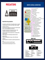
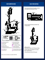
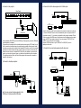
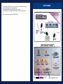
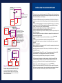
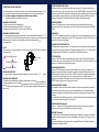
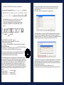
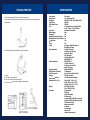
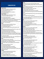
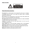
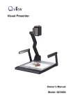
GENEE TECHNOLOGIES
INDIA PRIVATE LIMITED
®
An ISO 9001:2008 certified company
Classroom for the Future
6100
®
6100
Classroom for the Future
Tel: 0124-4934500
@ Email: [email protected]
Website: www.genee-india.com, www.geneeworld.com
WWW
Plot No. 698, Udog Vihar, Phase V, Gurgaon, Harana-122016, India
Fax: 0124-4934521
User manual
PRECAUTIONS
REMOTE CONTROL & CONNECTIONS
POWER (Control the visualiser On/Off)
SAVE (Save captured images)
RECALL (Display saved images)
EXIT (Exit RECALL mode)
LAMP (Control the arm lights and back light)
FREEZE (Freeze the image)
NEG (Display film negatives)
MIRROR (V-Reverse the image)
SPLIT (Image split function)
D./S. (Switch between static mode and dynamic mode)
XGA (Switch between XGA (1024 x 768) and SVGA (800 x 600) mode)
B&W (Switch between color mode and B&W mode)
TITLE (Freeze the top 1/8 of the screen)
PROJECTOR POWER (Control the projector On/Standby)
PROJECTOR INPUT (Projector input signal selection)
TEXT (Switch between image/text mode)
AUTO (To auto white balance and auto focus)
TELE/ IDE (Increase and decrease the magnification)
FAR/NEAR (Focus near or far)
VOL+/VOL- (Increase or decrease the volume)
CCD/PC1/PC2 (CCD/RGB input signal selection)
VIDEO (Video input signal selection)
RED +/- (Increase/decrease the red hue)
BLUE +/- (Increase/decrease the blue hue)
BRIGHT +/- (Increase/decrease the brightness)
SCROLL / (Move the image up/down)
Please follow these precautions:
To prevent fire or shock hazard, do not expose the unit to rain or moisture.
To prevent electrical shock, do not open the cabinet. Refer to qualified
personnel for service only.
Do not use the unit continuously for more than 24 hours with camera auto
focus on. It may cause damage to the camera lens.
Be careful not to spill water or other liquids onto the unit, or allow
combustible or metallic objects to get inside the cabinet.
Unplug the visualiser from the wall outlet when it is not being used for a
long period of time.
Clean the cabinet with a soft cloth lightly moistened with a mild
detergent solution.
Clean the lens carefully with an air spray or soft dry cloth to avoid
scratching it.
When the lamps flash or become dark, they should be replaced with new
ones.
Avoid switching arm lights and back light frequently.
Remove the camera lens cap before power the unit on.
NOTE: FREEZE, TITLE, D./S. and SPLIT functions
are only available on PROJECTOR OUT port.
REAR PANEL
7
OUT
OUT
AUDIO VIDEO
S-VIDEO
IN
8
IN
AUDIO VIDEO
AUDIO
S-VIDEO AUDIO IN
OUT -COMPUTER- IN
PROJECTOR
OUT-12V- IN
Panel
PANEL
SIDESide
18
PROJECTOR MIC
USB
RGB IN
AUDIO IN
2) VIDEO OUT
1) AUDIO OUT
5) VIDEO IN
4) VIDEO AUDIO IN
8) PC AUDIO IN
7) S-VIDEO IN
11) COMPUTER IN
10) COMPUTER OUT
13) PROJECTOR RS232 Connector
16) RGB IN
15) USB Connector
18) COMPUTER RS-232 Connector
RS232
3) S-VIDEO OUT
6) S-VIDEO AUDIO IN
9) PROJECTOR Connector
12) POWER OUT/IN 14) MIC IN
17) RGB AUDIO IN
BASIC PREPARATIONS
PARTS IDENTIFICATION
1. Use one hand to hold the base of the visualiser, use the other
hand to carefully lift up the camera stand of the unit.
Camera
Camera stand
Arm lights
Button instruction
Connectors
2. Open the arm lights and rotate the camera head until they
are in proper positions.
Back light
Remote control slot
Connectors
Stage
Operation panel
Arm lights
CCD/PC1/PC2
6100
6100
Mir
Frz
Neg
VIDEO
Title
Far
Ppw
Pin
POWER (Control the visualiser On/Off)
Mir (V-Reverse the image)
Frz (Freeze the image)
Neg (Display film negatives)
Title (Freeze the top 1/8 of the screen)
D./S. (Switch between static mode and dynamic mode)
Far/Near (Focus far or near)
Split (Image Split function)
POWER
+
LAMP
T
W
AUTO
Ppw (Control the projector On/Standby)
Pin (Projector input signal selection)
/ (Move the image up/down) (Optional)
CCD/PC1/PC2 (CCD/RGB input signal selection)
VIDEO (VIDEO input signal selection)
LAMP (Control the arm lights and back light)
AUTO (To auto adjust white balance and auto focus)
T/ (Increase and decrease the magnification)
Remarks: Frz, Title, D./S. and Split functions are only available on PROJECTOR OUT.
3. Making connections:
Before making any connection, turn off all the power, including
power of the visualiser and the equipment to be connected.
Step 1: Connect power source.
First connect the power cord to the 12V IN connector.
4: Connect to the projector.
6: Connect to the first video equipment with S-Video input.
Rear Panel
OUT
OUT
AUDIO VIDEO
IN
S-VIDEO
AUDIO VIDEO
S-Video Cable
S-Video out
IN
AUDIO
S-VIDEO AUDIO IN
PROJECTOR
OUT -COMPUTER- IN
OUT-12V- IN
Audio out
Video equipment
Rear Panel
OUT
AUDIO
RS232 Cable
Side Panel
RGB IN
AUDIO IN
AUDIO
VIDEO
AUDIO
S-VIDEO
AUDIO IN
RS232
Connect visualiser’s PROJECTOR port to the RGB IN port of the projector port with the RGB cable
provided together the visualiser.
If you need control a projector with the visualiser, please use the projector RS232 cable (6-pin to
9-pin) to make the connection between the projector and the visualiser. Some projector models
may require a converter cable in addition to this standard RS232 cable to connect to the projector
control port, for the pin locations and shape of some projectors’ control port connector may be
different from the connector of a standard RS232 cable. After the visualiser is connected to the
projector, you can control projector’s power on, standby and input selection with the visualiser.
(For projectors other than Hitachi, the Code Writing program that comes with the visualiser is
required for this function.)
Video Cable
Video out
Audio out
Video equipment Audio out
Rear Panel
Rear Panel
OUT
IN
OUT
VIDEO
S-VIDEO
AUDIO
AUDIO
OUT
IN
IN
IN
VIDEO AUDIO
S-VIDEO
VIDEO
S-VIDEO AUDIO
AUDIO IN VIDEO
PROJECTOR
AUDIO
OUTS-VIDEO
-COMPUTER- AUDIO
IN
Projector Color monitor
Video in
Video in
Rear Panel
AUDIO VIDEO
S-VIDEO
AUDIO VIDEO
AUDIO
S-VIDEO AUDIO IN
PROJECTOR
OUT -COMPUTER- IN
OUT-12V- IN
Side Panel
To the
Monitor
PROJECTOR MIC
USB Connector
RGB Output
USB
Side Panel
RGB IN
AUDIO IN
RS232
RS232
Cable
Computer
PROJECTOR MIC
USB
RGB IN
PROJECTOR MIC
USB
RGB IN
AUDIO IN
AUDIO IN
RS232
RS-232 cable
USB cable
Note: You can connect a laptop computer to the
RGB IN port of side panel with a RGB cable.
OUT-12V- IN
Video out
AUDIO
IN
IN
Video Cable
Projector Color monitor
IN
-COMPUTER-
7: Connect to the second video equipment with video input.
OUT
OUT
OUT
Output of the S-Video signal from the visualiser to the projector is already done in the step
2, where the RGB cable comes out from the visualiser and goes to the projector. After the
connections as steps 2, 3, 4 are made, input signals from the computer visualiser CCD and
S-Video are going to the RGB1 input on the projector and will be displayed on the projector
screen as RGB1. These signals can be seen in turn when pressing “CCD/PC1/PC2” and
“VIDEO” on the control panel of the visualiser.
Remarks: RGB IN signal can not go to S-VIDEO OUT or VIDEO OUT port to be
displayed on the screen.
Video equipment
5: Connect to a desktop computer.
OUT
PROJECTOR
Audio input
Screen
Projector
USB
S-VIDEO
Projector
(or amplifier/speaker equipment)
RGB Input
PROJECTOR MIC
VIDEO
IN
IN
OUT
RS 232 connector
RS232
of the computer
Side Panel
USB connector
of the computer
USB cable
RS-232 cable
RS 232 connector
of the computer
USB connector
of the computer
IN
OUT-12VIN
PROJECTOR
OUT
-COMPUTER-
IN
OUT-12V- IN
SETUP GUIDE
Use the computer RS232 cable (9-pin to 9-pin) to make the connections shown below
to control the visualiser from an external computer.
USB connection enables capturing still images / video streams
from the visualiser to the computer. Special software is required for this operation.
8. Turn on the power by pressing the “POWER” button.
Plug
in here
Plug monitor/pc in here
INSTALLING VISUALISER SOFTWARE
Set up 1
USB
Set up 1
RGB in
projector
comp in
The simplest set-up, using
the RGB lead, to project
images on to a screen.
PROJECTOR
Set up 2
LAPTOP 2
USB
RGB
RGB in
?
projector
USB
comp in
RGB
MAIN PC/
LAPTOP
PROJECTOR
connected to
interactive board
Set up 3
Set up 2
This set-up allows you to
toggle between the Visualiser,
the PC / laptop running
the interactive whiteboard
and an optional, second
(non-interactive) computer
input. The USB lead can be
connected to either computer
depending on which one you
wish to capture Visualiser
images on to.
USB
1. Insert the CD-ROM that comes with your visualiser into the CD-ROM drive. If Autorun is
enabled on your system, then the Software Setup window will be displayed automatically as
below.
If it does not start automatically, after inserting the CD-ROM, Click [Start] -> [My Computer],
and double click (the CD-ROM drive letter might be different among different computer
systems), then the above screen will appear immediately.
2. Click the Install Code-Writing Program button to install Code-Writing Program.
3. Click the Install DirectX9.0 button to install Microsoft DirectX 9.0.
4. Click the Install Capture Program button to install the program that captures images in the
AVI or Bitmap format.
5. Click the Install USB Driver button to install the driver designed for the visualiser and will
be used by the Capture Program.
6. After the installation is finished, then click the Exit button to exit the Software Setup
window.
7. Shut down your computer when prompted so the changes will take effect.
8. Use the USB cable to connect your computer to the visualiser before your computer is
restarted.
9. Turn on the visualiser.
Remarks: DirectX9.0 is not necessary to install, it is mainly for computer print screen function.
Please pay attention to the following:
10. Computer hardware requirement: CPU: Pentium 4, RAM: 256M or above, USB 2.0 port,
Hard disk 40G or more.
(front)
USB
11. Operating system: Windows 2000 or above. If the operating system is Windows 2000,
should install SP4. If the operating system is Windows XP, should install SP1.
projector
12. Must use the high-speed USB cable provided together with the visualiser.
comp in
13. When connect the visualiser to a desktop computer with the high-speed USB cable
provided together with visualiser, we recommend using the USB port on the rear of the
mainframe as the USB port on the front of the computer might have interference.
USB RGB
PROJECTOR
This function is to snap and display images with the USB interface, which includes displaying
static and dynamic pictures, snapping dynamic images and playback the dynamic images with
the Windows Media Player or its own player.
PC/LAPTOP
14. You need to install the USB driver again when you change a computer’s
USB port. If this port has installed USB 2.0 driver, then no need to install USB driver again.
Set up 3
15. When you open capture program, but can not capture the image, please set the signal
input source: click “Option” “Video Crossbar”, and then set INPUT as S-Video IN.
SET UP GUIDE
This set-up allows you toggle between the Visualiser and the
interactive desktop, using the CCD/PC1/PC2 button (no input
on PC2). Any Visualiser still-image can be captured to the
desktop using the ‘VideoCap’ software (on the Genee Vision
disk), or moving image using programs such as ‘Movie Maker’
which comes with Windows XP.
Copy the folder “Mac Driver” into Mac hard disk, open the folder and double-click Empia 1.0.0b2.
zip, the “setup” file appears. Follow dialog-box messages, click “next” and finish installation.
Note: 1. Please connect Mac computer and visualiser when installing
2. Please use USB2.0 from visualiser accessories.
PROJECTOR INPUTS SELECTION
When the projector is connected to several input sources, use the “Pin” button to switch signal
inputs of the projector. (On the remote control, press the “PROJECTOR INPUT” button) Note: Please
connect the projector RS232 cable between the projector and the visualiser first. If you cannot switch
projector inputs by pressing this button, you need to manually program the RS232 code into the
visualiser. See the section “Controlling Projector with Visualiser” for detailed instruction.
WORKING ON THE STAGE
1. Place your material on the working surface.
2. Select the enlargement required with the “ T” and “W” keys.
3. Adjust the focus with the “Near” and “Far” keys or “AUTO” key.
IMAGE REVERSION
Press the “Mir” button once to V-reverse the image and the vertically mirrored image will be
displayed. Press the “Mir” button again to exit. (On the remote control, please press the “MIRROR”
button)
WORKING OUTSIDE THE STAGE
For showing 3-dimensional objects, just place them on the working surface and adjust the “ T” or
“W” and “AUTO” keys. If the object is too big for the stage or you want to show it from the side, just
place it behind or in front of the unit and tilt the camera by hand (please take off the
close-up lens first).
IMAGE SPLIT
Press “SPLIT”, the image will be split into two images. One is the current captured image the other
is a frozen image of the last image, Press the “SPLIT” button again to exit. Note: This function is not
available on S-Video and Video output.
USB CAPTURE FOR MAC COMPUTER
LIGHT
The arm lights are on when the power is on. Each time you press the “LAMP” buttons, the lighting
changes as below.
The arm lights turn on
Rotate 330 degrees
vertically
The back light turns on
All the lights turn off
ADJUSTING IMAGE SIZE
In order to reduce or enlarge the image size displayed on the screen, press the “ T” or “ ” button.
WORKING WITH NEGATIVES
The visualiser is automatically set to display normal materials on the screen when the power
W is on.
To display negatives, turn on the backlight by pressing the “LAMP” key, and then press the “Neg”
button to display the film negatives. Press the “Neg” button again to display normal materials in the
colour mode.
DYNAMIC/STATIC MODE SWITCH
To display dynamic images, Press the “D./S.” button to switch to the Dynamic mode, the image will
be clear and has no choppy strobe effect. To display still images, press the “D. / S.” button switch to
the Static mode.Note: This function is not available on S-Video and Video output.
TITLE FUNCTION
Press the “Title” button once, the image split into two parts, the upper 1/8 part of the image will
freeze and stay on top 1/8 of the screen. Press “Title” button again to exit the Title mode. Note: This
function is not available on S-Video and Video output.
IMAGE SAVE AND RECALL
Press the “SAVE” button once to save one captured images, it can save up to 7 images. After 7
images are saved, the 8th image will replace the previous 1st image and will become the new 1st
saved image.(On the remote control) Press the “RECALL” button once to display the saved images,
then press the numerical button to show the corresponding image. For example: Press “2” to
display the second image. At this status, the function under each numeric key is not available. Press
“RECALL” again to exit this mode. (On the remote control)
INFRARED REMOTE CONTROL
The visualiser’s remote control can control the camera from different angels. Please note that an
infrared remote control can only be used up to a certain distance to the unit. Objects situated
between the visualiser and the infrared remote control and a weak battery may interfere with the
reception.
On the left side of the visualiser stage, there is a built-in remote control storage compartment where
you can store the remote control when you not use it.
IMAGE SCROLLING (Optional)
Press the “ ” button to scroll the image down to display the upper part of the image. Press the “
button to scroll the image up to display the lower part of the image.
USB PORT (Optional)
The USB port can be used to transfer still images from the visualiser to a computer. No additional
computer hardware is required. In this way, the visualiser can be used as a 3-D scanner for your
computer.
Connect the visualiser to your computer with the supplied USB cable. The Visualiser Software is
available on the supplied CD-ROM.
SWITCHABLE RGB INPUTS
Use the “CCD/PC1/PC2” button to switch between CCD and different RGB signals. Each time
the “CCD/PC1/PC2” button is pressed, it provides seamless transitions among different sources
such as Camera (CCD), COMPUTER(IN) and RGB (IN). Notes: COMPUTER OUT always outputs
COMPUTER IN signals.
FOCUSING
When the visualiser is turned on the focus automatically adjusts to the stage, it is not
necessary to readjust the focus if you are only working with flat materials (text, photos, etc.).
Only 3D object require a focus adjustment. Press the “AUTO” button to auto focus. Press the
“FAR” or “NEAR” button once to focus manually.
PROJECTOR ON/STANDBY
Press the “POWER” button to turn on the visualiser’s power and press the “Ppw” button to
turn the projector power on. To turn the projector standby after use, press the “Ppw” button
more than 2 seconds, and then the projector enters to the stand-by mode. (On the remote
control, press the “PROJECTOR POWER” button) Note: Please connect the projector RS232
cable between the projector and the visualiser first. If you cannot switch projector inputs by
pressing this button, you need to manually program the RS232 code into the visualiser. See
the section “Controlling Projector with Visualiser” for detailed instruction.
FREEZING IMAGE
Press the “Frz” button to freeze the image. When the output signal is RGB, in order to show
a still image on the screen, press the “Frz” button. The frozen image can’t be adjusted (Zoom
in/out, color adjustment, etc.). Note: This function is not available on S-Video and Video
output.
PROJECTOR INPUTS SELECTION
When the projector is connected to several input sources, use the “Pin” button to switch signal
inputs of the projector. (On the remote control, press the “PROJECTOR INPUT” button)
Note: Please connect the projector RS232 cable between the projector and the visualiser first.
If you cannot switch projector inputs by pressing this button, you need to manually program
the RS232 code into the visualiser. See the section “Controlling Projector with Visualiser” for
detailed instruction.
IMAGE REVERSION
Press the “Mir” button once to V-reverse the image and the vertically mirrored image will
be displayed. Press the “Mir” button again to exit. (On the remote control, please press the
“MIRROR” button)
IMAGE SPLIT
Press “SPLIT”, the image will be split into two images. One is the current captured image the
other is a frozen image of the last image, Press the “SPLIT” button again to exit. Note: This
function is not available on S-Video and Video output.
DYNAMIC/STATIC MODE SWITCH
To display dynamic images, Press the “D./S.” button to switch to the Dynamic mode, the image
will be clear and has no choppy strobe effect. To display still images, press the “D. / S.” button
switch to the Static mode.
BRIGHTNESS ADJUSTMENT
If the image effect is not satisfactory, you can adjust the brightness to get a better image
effect. Use the “BRIGHT +” or “BRIGHT -” button to adjust the brightness. To increase the
brightness, press the “BRIGHT +” button. To decrease it, press the “BRIGHT -” button. To go
back to the initial brightness press the “AUTO” button.
WHITE BALANCE ADJUSTMENT
Each time the lighting condition changes, the user should adjust the white balance of the
CCD. Press the “AUTO” button to adjust the white balance automatically.
AUTO ADJUSTMENT
One of the visualiser’s special functions is auto adjustment. Press the “AUTO” button to auto
adjust the white balance and the focus. The whole process takes about 10 seconds.
TEXT/IMAGE MODE
Press the “TEXT” button to switch between image/text modes. Todisplay a text file, switch to
the text mode to get a clearer text effect. (On the remote control)
COLOR AND B&W MODE SWITCH
Press “B&W” once to enter the Black & White mode; Press again to return to the Color mode.
SWITCHABLE VIDEO INPUTS
Press the “VIDEO” button to switch among S-Video and Video signals.
SWITCHABLE RGB INPUTS
Use the “CCD/PC1/PC2” button to switch between CCD and different RGB signals. Each
time the “CCD/PC1/PC2” button is pressed, it provides seamless transitions among different
sources such as Camera (CCD), COMPUTER(IN) and RGB (IN). Notes: COMPUTER OUT
always outputs COMPUTER IN signals.
PROJECTOR ON/STANDBY
Press the “POWER” button to turn on the visualiser’s power and press the “Ppw” button to
turn the projector power on. To turn the projector standby after use, press the “Ppw”
button more than 2 seconds, and then the projector enters to the stand-by mode. (On the
remote control, press the “PROJECTOR POWER” button)Note: Please connect the projector
RS232 cable between the projector and the visualiser first. If you cannot switch projector
inputs by pressing thisbutton, you need to manually program the RS232 code into the
visualiser. See the section “Controlling Projector with Visualiser” for detailed instruction.
CONTROLLING THE VISUALISER
FROM A COMPUTER
You can control the visualiser from a computer connected with an RS232 connector.
1. Connect the computer and the visualiser with the computer RS-232 cable (9-pin to 9-pin).
2. Select [Start] -> [Program] -> [VideoCap]
3. Click “Control Panel” under “Capture”.
D. Select the COM port COM1 or COM2 and you can control
the visualiser by clicking the buttons on the menu.
Toolbar:
Control: Control the visualiser by a computer through RS232 cable.
Capture one frame: CONTROLLING THE PROJECTOR
WITH THE VISUALISER
The code writing software is used to inputting projector’s control code, then can control
various projector with the visualiser.
1. Connect the visualiser to the projector with the RGB, VIDEO, S-VIDEO cables.
2. Connect the RS232 cable to the computer’s connector. The visualiser’s RS232 port is
located on its right side.
3. After completion of the connection, turn on the visualiser, click [start] ->
[All Programs] -> Visualiser ->
and the following dialog box appears as below:
When the indicator of “Current RS-232 Connection Status” is green, that means the
connection between the visualiser and the computer’s RS232 connector is good. If the
indicator is red, please check if the RS232 cable is connected correctly. When all the
cables are connected correctly, please click “Projector” to select your projector model
under the drop-down list, then click “Send”. If you cannot find your particular projector
model in the “Projector”, please do the following:
Capture the current preview image and save it to the desired path.
Full Screen: Full screen display the preview content, left double click to exit.
Start Capture: Start to video capture
Stop Capture: Stop video capture
VIDEO DISPLAY AND CAPTURE (Optional)
You can capture and control images on the visualiser from a computer connected
with a USB connector.
Click [Start] -> [Program] -> [VideoCap] -> “VideoCapx.xx” (x.xx is software’s
version) to open the software.
1. Static Images Snap
Click “Capture”—>“Capture Frame”, input the file name in dialog box, or you can
click
icon on the toolbar, then input file name in dialog window. The image file
is JPG format.
2. Snap Video Stream
Click “Capture”—> “Start Capture”, input the file name in dialog box, or click
icon on the toolbar, then input the file name in dialog box. If you want to set the
time limit for the capture, select “Capture” ->“Set Time Limit“ to set the time
limit. Click “Start Capture” to start capture, and click “Stop Capture” or
icon on
the toolbar to stop capture. (If you have set the time limit, it will stop automatically when the time is up.) The video file is AVI format.
3. Set the Frame Rate
Click [Capture] -> [Set Frame Rate], and click open “Choose Frame Rate” to set
the frame rate.
4. Set Time Limit
Click [Capture] -> [Set Time Limit] to set the time limit while capturing video.
When the indicator of “Current RS-232 Connection Status” is green, that means the
connection between the visualiser and the computer’s RS232 connector is good. If the
indicator is red, please check if the RS232 cable is connected correctly. When all the
cables are connected correctly, please click “Projector” to select your projector model
under the drop-down list, then click “Send”. If you cannot find your particular projector
model in the “Projector”, please do the following:
1 Select “Baud rate” and “parity” and input the projector control code. (The baud
rate, parity and control code is supplied by projector’s manufacturer, please refer to the
projector’ manual)
The input format of projector’s control code is as follows:
If the data is in the numerical value format, please input data directly, block them off
with comma, do not distinguish lowercase and uppercase.
For example: the “POWER ON” code in Hitachi projector manual is :
01 00
BA D2
BE EF 03 06 00
6. If you can not use buttons on the operation panel to control the projector, please
use Code-Writing software’s projector control code testing function to check if the
control code is correct.
Click “Projector” button, the following dialog box appears as below:
01 00
00 60
In the POWER ON box, Input : be, ef, 03, 06, 00, ba, d2, 01, 00, 00,
60, 01, 00. Then use the same input rule to input other code.
b. If the data is in the character string format, input ‘character string’.
For example: the “POWER ON” code in the SHARP C40/50 projector
manual is :
P
O
(“-“ is space
W
E
-
-
-
1
Connect the visualiser to a computer with a RS232 cable (Please disconnect the projector
from the RS232 port first) and select the Baud Rate and Parity based on the projector’s
Baud Rate, then click the “TEST” button to pop up the Projector Code Test dialog box, input
the Baud Rate and Parity based on the projector’s Baud rate, then click “Open”.
is enter.)
In the POWER ON box, input ’POWR 1’, 0d, 0a
(Remarks: There are 3 spaces after POWER, 0d, 0a is enter.)
Input other codes in the same way.
4. If the data is in the numerical value and character format, then synthesize the
above-mentioned formats.
3. Once done, click “Add” to add your projector model, then Click “Send”. Afterward,
click “Ok”. Now, you can use the visualiser to control your projector.
5. Connect the visualiser’s projector control port to the RS232 port with a RS232
cable. Please disconnect the computer from the RS232 port first. Then use
buttons on the operation panel to control the projector.
5
6
4
3
21
The visualiser provides a 6-pin to 9-pin RS232 cable. If this cable does not match
to your projector’s RS232 port, an additional RS232 cable is needed. This additional
RS232 cable can be made based on the pin location of the projector’s RS232 control
port. The pin locations of the visualiser are: the pin 1 is RXD (Received Data); the
pin 5 is TXD (Transmitted Data); the pin 4 is GND (Ground). Other pins are not
defined. The pin location information of the projector is provided by the projector’s
manufacturer. The projector’s RS232 control port normally has RXD pin, TXD pin and
GND pin, the name may be different. The parallelism of each data pin is shown as
follows:
Visualiser’s RXD pin------------Projector’s TXD pin
Visualiser’s TXD pin------------Projector’s RXD pin
Visualiser’s GND pin------------Projector’s GND pin
Click the projector control buttons on the visualiser’s operating panel to check if the control
code that the program received is the same as the sending code. If the receiving code is
same to the sending code, the input codes are correct. If the visualiser cannot control the
projector, please do the following.
1. Check to see if the source control codes of projector are correct.
2. Check to make sure the connection between the visualiser and the projector is correct.
SET UP GUIDE
FOLDING THE UNIT
1. Fold the right arm light down first onto the base, then the
left arm down. Rotate the camera head clockwise until the camera head is parallel to the
camera stand.
2. Carefully fold the camera stand down to the front panel.
Cautions:
a. Don’t lay the unit down flat.
b. Don’t try to stand it on its rear or sides.
c. Don’t try to pick up this unit by pulling the camera stand.
NOT THIS WAY
SPECIFICATION
Color system Pickup device Resolution Total Pixels RGB Output Pixels Lens Focus/Iris White balance Image split Negative/positive conversion Black/white and color selection Image Freeze Mirror Lights Input connectors Output connectors Operating system
USB connector (Optional) RS-232 connector USB port Power requirements Dimension (W x D x H) Weight Accessory PAL system
1/4″professional CCD
XGA (1024 x 768), SVGA (800 x 600)
470,000
780,000
22 x optical zoom, 10 x digital zoom
F=1.6~3.7mm / f=3.9~85.8 mm
Auto/manual selectable
Auto
Yes
Yes
Yes
Yes
Yes
Arm light: 1.5 W LED lamps x 2
Back light: LED lamp
C-Video: RCA jack 1
S-Video: 4 pin mini Din 1
Audio: Mini jack 2
MIC: Mini jack 1
PC Audio: Mini jack 2
RGB:DB15FLC 2
RGB DB15FLC 2
C-Video: RCA jack 1
S-Video: 4 pin mini Din 1
Audio: Mini jack 1
Windows 2000/XP
25 frames/sec
9-pin, D-Sub, male/6-pin PS/2
USB 2.0 (Optional)
12V/4A external AC adapter
Folded: 20.0″ x 16.1″ x 4.7″
Setup: 20.0″ x 20.9″ x 22.4″
Packing: 25.6″ x 21.2″ x 9.1″
N.W: 5.5Kg (12.1lbs)
G.W : 7.5Kg (16.5 lbs)
AC power cord
RGB cable
Audio/Video cable
S-Video cable
Computer RS232 cable (9-pin to 9-pin)
Projector RS232 cable (6-pin to 9-pin)
USB cable (Optional)
Audio convert cable
AC adapter
User’s manual
Software CD
Infrared remote control
EXAMPLES OF USES
Religious Education
• Share resources easily by placing underneath visualiser and projecting.
• Grab lesson objective and hold at the top of the screen.
• Use to share good examples of pupil’s work
• Use to instantly capture examples of pupil’s’ work for assessment.
• Use to display images of artefacts.
Design & Technology
• Share resources easily by placing underneath visualiser and projecting.
• Grab lesson objective and hold at the top of the screen.
• Use to share good examples of pupil’s work
• Use to instantly capture examples of pupil’s’ work for assessment.
• Use zoom facility to view objects in more detail i.e. PCB. Combine with split screen and freeze
frame to view both sides of an object then remove object from underneath camera.
• Work live underneath camera to demonstrate a technique or process – capture using Windows
Movie maker for use as a teaching resource.
Science
• Share resources easily by placing underneath visualiser and projecting.
• Grab lesson objective and hold at the top of the screen.
• Use to share good examples of pupil’s work.
• Demonstrate practical investigations underneath camera so that whole class can view on
screen.
• Capture demonstration using Windows Movie maker and play back as part of plenary or post on
VLE as a learning resource for pupils to access after the lesson.
• Use to instantly capture examples of pupil’s work for assessment.
• Angle camera out of doors to view habitats i.e. pond or bird nesting site.
• Place an experiment which involves time lapse i.e. growing seeds or decaying food underneath
camera and take snapshots at regular intervals to show changes taking place. Drop into Windows
Photo Story to play back in sequence.
• Use zoom facility to view small objects in more detail i.e. plants. Combine with split screen facility to hold image of a plant whilst identifying in a reference book.
Drama
• Use to mock up stage sets and view from different angles.
• Use camera as a web cam to either display a live performance on a big screen or to capture in
Windows Movie maker for viewing or critical analysis at a later time.
• Use with 2Simple 2 Animate to create simple animation movies with sound and dialogue.
PHSE
• Grab lesson objective and hold at the top of the screen.
• Use to share good examples of pupil’s work
• Use to instantly capture examples of pupil’s’ work for assessment.
• Use as a webcam to capture extracts of drama for replay and discussion.
• Lower arm and capture modelled scenes then use story board software to produce short film to
include music and spoken voice.
Geography
• Share resources easily by placing underneath visualiser and projecting.
• Grab lesson objective and hold at the top of the screen.
• Use to share good examples of pupil’s work
• Use to instantly capture examples of pupil’s’ work for assessment.
• Use zoom facility to view artefacts in more detail i.e. rocks or soil samples.
Literacy
• Share teaching resources easily by placing underneath visualiser and projecting.
• Easily grab parts of text and place into whiteboard software or Word for further discussion and
annotation.
• Pupils use ‘Windows Photo Story’ with captured images to create stories - could also add spoken
dialogue to create a speaking and listening task.
• Instantly share good examples of pupil’s work as part of plenary.
• Use split screen facility to easily compare 2 texts.
• Use negative facility to reverse text i.e. white on black for ease of reading.
• Place text underneath visualiser then freeze frame so that whole class can view text after book is
removed.
• Place book being read underneath camera and use pointer or finger to allow pupils to follow text
being read.
• Grab lesson objective and hold at the top of the screen.
• Use a live example as a stimulus for writing i.e. show a text message for a task to write a set of
instructions. Capture in Windows Movie Maker and play back as many times as needed, pausing to
discuss language and vocabulary to be used.
MFL
• Share resources easily by placing underneath visualiser and projecting.
• Grab lesson objective and hold at the top of the screen.
• Use to share good examples of pupil’s work
• Use to instantly capture examples of pupil’s’ work for assessment.
• Lower arm and capture modelled scenes then use story board software to produce short film to
include music and spoken voice.
Numeracy
• Share resources easily by placing underneath visualiser and projecting.
• Grab lesson objective and hold at the top of the screen.
• Use mirror feature when teaching reflection or symmetry.
• Place coins or counters on surface then split screen. Work live on right hand side of screen to
demonstrate by moving counters how to divide up the number.
• Use a live example to demonstrate a particular operation i.e. show an apple being cut up to
demonstrate fractions. Capture in Windows Movie maker then play back and pause as appropriate
to discuss/annotate.
• Use to show 3D shapes so that everybody can see shape.
• Use to instantly capture examples of pupil’s’ work for assessment.
• Use to share good examples of pupil’s work
ICT
• Share resources easily by placing underneath visualiser and projecting.
• Grab lesson objective and hold at the top of the screen.
• Use to share good examples of pupil’s work.
• Use to demonstrate equipment that is usually too small for everybody to see i.e. handset for voting system, PDA screen, camera, GPS.
• Use to instantly capture examples of pupil’s work for assessment.
Art
• Share resources easily by placing underneath visualiser and projecting.
• Grab lesson objective and hold at the top of the screen.
• Use to share good examples of pupil’s work
• Use to instantly capture examples of pupil’s’ work for assessment.
• Angle camera to view artefacts from different angles.
• Use colour on/off facility to study effects of colour on tone/shade/impact.
• Work live underneath camera to demonstrate a technique or process – capture using Windows
Movie maker for use as a teaching resource.
• Use negative feature to view images in differing formats.
• Use split screen to show and compare two objects or two paintings.