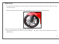
1
Sport 250RR
User Manual
1
Preface
Congratulations on the purchase of your new Megelli. We thank you for choosing our product and take this opportunity
to welcome you to Megelli motorcycles.
This booklet is an integral part of your motorcycle and should remain with the bike for the duration of its life.
We ask you to read the contents and ensure you are familiar with the maintenance, controls and safety aspects of the
bike prior to riding. Should you have any questions regarding its function or operation, please contact a Megelli
authorized dealer.
The content of the manual represents the Sport 250RR motorcycle. Megelli reserves the right to introduce changes to
the product as part of its commitment to a program of continuous improvement.
2
Contents
Page
Introduction...............................
¾
7
Bike detail
Identification .............................
8
Delivery……………….……....
10
¾
¾
PDI
Records
Controls/Features………..........
11
Safety-General ..........................
26
Safety/Pre-Ride Checks……….
27
¾
¾
Rider
Bike
3
Contents
Operation...................................
¾
¾
¾
¾
¾
¾
¾
¾
¾
¾
Starting the Engine
Stopping the Engine
Running in
Riding
Braking
Gear selection/Riding
Steering lock
Side Stand
Fuel Tank
Seat Removal
30
30
32
33
34
35
36
37
38
39
40
Maintenance..............................
¾
¾
¾
¾
Service Schedule
Access
Engine
Chain Adjustment
41
42
43
44
45
4
Contents
¾
¾
¾
¾
¾
¾
¾
¾
¾
Brakes
Clutch
Suspension
Lubrication
Battery, Electrical
Lights
Air Filter
Wheels/Steering
Tyres
47
51
52
54
55
57
62
63
65
Technical Specification………….
¾
¾
¾
¾
¾
¾
¾
Engine
Transmission
Electrical
Dimensions
Chassis/Wheels/Tyres
Capacities
Fluid Grade
66
66
67
68
69
70
71
72
5
Contents
Cleaning/Care………………....
73
Storage…………………….......
75
Warnings…………………… ...
76
Environmental……………… ...
77
Parts…………………………...
78
Warranty……………………....
79
6
Introduction
The Megelli bike conforms to legislation of construction, operation, design and emissions, as required for use on public
highways.
There is provision for a single rider plus a pillion. It is equipped with a 4-stoke, air cooled engine with a battery
operated electric start function. The transmission has 6 manually selected gears with a chain drive to the rear sprocket.
The frame has a twin trellis construction with alloy outriggers and a tubular constructed rear swing arm.
Hydraulic 38mm forks are utilized for the front suspension with a mono-shock absorber for the rear.
Braking is via hydraulically operated front and rear disc brakes.
7
Identification
Each bike has an individual chassis number which is engraved on the headstock of the frame:
and a unique engine number engraved on the casing of the engine:
8
Identification
These numbers correspond to the details on the Pe-Delivery Instruction (PDI) and Warranty Manual.
It is advisable to make a note of these numbers and keep them in a safe location for future reference.
There is also a plate riveted to the chassis with details specific to the individual model and bike:
(Note: This plate may be in a different format in regions outside of Europe)
9
Delivery
Prior to receiving your new Megelli motorcycle, the supplying dealer will have conducted a Pre-Delivery Inspection
(PDI) of the bike. Please ensure you are entirely satisfied with the condition of the motorcycle, the terms of the
warranty, service schedule and the operation of the controls has been explained. A copy of the form with a list of
completed checks will be passed to you once it has been signed and dated by both the dealer and purchaser of the bike.
You should also remember your responsibility to ensure any legal requirements to permit usage on the highway are in
place before riding. For example tax, insurance, number plates, etc.
10
Controls/Features
R/H Side View
KEY
1. R/H Rear View Mirror
2. Instrument Panel
3. Lockable Fuel Cap
4. Rider Seat
5. Pillion Seat
6. R/H Pillion Footrest
7. Rear Suspension
8. R/H Rider Footrest
9. Rear Brake Pedal
10. Oil Level
11. Front Brake Lever
11
Controls/Features
L/H Side View
3
○
KEY
1. L/H Rear View Mirror
2. Steering Lock
3. Battery (under fuel tank)
4. Air Filter (under seat unit)
5. L/H Pillion Footrest
6. Gear Lever
7. L/H Rider Footrest
8. Side Stand
9. Chain
12
Controls/Features
Left-Hand Switch/Handlebar Assembly
KEY
1. Hand Grip
2. Clutch Lever
3. High-Low Beam Switch
4. Indicator Toggle
5. Horn Switch
6. Choke Lever
13
Controls/Features
Clutch Lever:
To disengage the clutch allowing gear selection, pull the lever towards the hand grip.
To engage drive, release the lever smoothly to prevent transmission damage .
14
Controls/Features
High-Low Beam Switch:
Position 1=Low Beam
Position 2=High Beam
Indicator Toggle:
Position 1=Turn Left
Position 2=Turn Right
Push to Cancel
15
Controls/Features
Horn:
Push button to activate
Choke Lever:
Move the lever in direction A to activate the choke
Move the lever in Direction B to disengage the choke
16
Controls/Features
Right-Hand Switch /Handlebar Assembly.
KEY
1. Throttle Grip
2. Starter Button
3. Light Switch
4. Engine Kill Switch
5. Front Brake Lever
17
Controls/Features
Light Switch:
Position 1=Lights Off
Position 2=Side Lights On
Position 3=Headlight On
Note. Operation may vary in countries
where their laws require.
18
Controls/Features
Throttle:
Rotate anti-clockwise to increase the revs
Rotate clockwise to reduce the revs.
Starter Button:
Press to activate starter. Release as soon as engine fires
19
Controls/Features
Kill Switch:
Switch to ‘Run’ position for engine to start/run
Switch to ‘Kill’ position to stop engine in an emergency
Front Brake Lever:
Pull lever towards handlebar with a smooth, but positive action to
apply the front brake.
20
Controls/Features
21
Controls/Features
Ignition Switch/Keys:
2 keys are supplied .
Position A=Ignition Off.
Position B=Ignition On-Circuits Activated.
Position C=Steering Lock-Push and turn anti-clockwise with
steering on full lock.
▲
Warning - Do not switch ignition off while riding.
Rev Counter:
Indicates the number of revolutions per minute (rpm).
!Caution - Never run the engine with the rpm in the red sector- a
red warning light will illuminate.
!Caution - Refer to the ‘Running in’ section for maximum rpm.
Green Turn Indicator:
Flashes when L/H or R/H indicator position is selected.
22
Controls/Features
Odometer/Tachometer:
Records accumulative distance traveled. Note: this should be set as either miles or km’s depending on relevant country
requirements.
Trip Meter:
Records distanced traveled and can be re-set to zero when required.
Press adjust button to access from odometer→trip meter →max record.
Blue Full Beam Lamp:
Illuminates blue when the high beam position is selected.
Amber Low Fuel Warning:
Illuminates when there is approximately. 1 litre of fuel remaining in the tank.
Blue Full
Digital Speed
Beam
Lamp
Amber Low Fuel
Warning
Trip Meter
23
Controls/Features
Clock Digital display:
¾ Press the ‘select’ button for 3 seconds to enter the hour adjusting mode.
¾ Pressing the ‘select’ button repeatedly will increase the hour digit (24 hour clock).
¾ Press the ‘adjust’ button to enter the minute adjusting mode.
¾ Pressing the ‘select’ button repeatedly will increase the minute digit.
¾ Press the ‘adjust’ button to save and exit the clock setting mode and return to the main screen.
Neutral Light:
When the neutral position is selected, the ‘N’ green light will illuminate.
Odometer:
Records the accumulative distance traveled. Note this should be set as either miles or km’s depending on relevant
country requirements.
24
Controls/Features
Trip Meter:
Records distance traveled.
¾ Press the ‘adjust’ button to enter the Trip Meter display.
¾ Press the ‘adjust’ button for 3 seconds to set the display to zero.
¾ Press the ‘adjust’ button twice to return to the main screen.
Max Record:
Records the maximum speed traveled.
¾ Press the ‘adjust’ button twice to enter the maximum speed display.
¾ Press the ‘adjust’ button for 3 seconds to set the display to zero.
¾ Press the ‘adjust’ button once to return to the main screen.
Battery Light:
Illuminates red when there is insufficient charge to the battery.
25
Safety-General
▲ Warning-Never touch engine or exhaust when they are still hot.
▲ Warning-Always keep body extremities and clothing away from any moving part.
▲ Warning-Do not expose unprotected skin to fluids used in the motorcycle. When
working with such fluids, always use protective clothing.
! Caution - Motorcycles are heavy and should be handled with care to avoid injury.
Always seek assistance when required.
26
Safety/Pre-Ride Checks
Safety First:
Rider-Prior to riding the bike.
¾
¾
¾
Ensure you have received adequate training on riding skills and knowledge of highway rules and regulations.
Familiarize yourself with the controls of the bike and ensure that you have fully read and understood the manual.
If you are unclear or unsure of any aspect, seek the assistance of a qualified Megelli agent or instructor.
¾
Protective clothing should be worn while riding the bike. This should include an approved helmet
and appropriate apparel.
¾
No additional items should be carried on the bike which may impede access or operation of the controls or make
the bike un-balanced.
27
Safety/Pre-Ride Checks
¾
¾
¾
¾
¾
¾
¾
¾
¾
¾
Always ride within your limits and experience.
Always keep your feet placed on the footrests and your hands on the handlebar grips.
Pillion passengers must always keep feet placed on the footrests.
Do not attempt to alter settings on the instrument console while riding.
Do not overload the bike. Adjust tyre pressures and suspension settings to suit the loading of the bike.
(see tyres pressure, suspension settings & loading capacities).
Do not ride while under the influence of drugs, alcohol or any medication which may adversely affect your
reactions.
Take account of the road conditions and ride accordingly, reducing speed if necessary.
Ensure the bike is road worthy and all lights are clear from dirt.
Adjust the rear view mirrors to suit the rider.
Do not ride off-road.
28
Safety/Pre-Ride Checks
Bike-Prior to riding the bike on every journey, check:¾ Ensure sufficient fuel to complete journey or reach the next fueling station.
¾ Oil level (see page 44).
¾ Brake fluid level(see page 49&50).
¾ Tyre pressure (page 70).
¾ Tyre tread and condition(see page 65).
¾ Lights, indicators and horn are functioning correctly.
¾ Brake operation/Brake pad wear (see page 35 & 47).
¾ Steering is smooth from lock to lock.
¾ Suspension is operational without fluid leaks.
¾ Chain adjustment/lubrication(see page 45 & 46).
¾ Side Stand is fully retracted (see page 38).
¾ Ensure the bike has not been modified in any way including the addition of accessories
other than official Megelli items.
¾ All fixings are in place and secure.
¾ As the engine warms, gradually move the choke lever to the ‘Off’ position.
29
Operation
Starting the Engine
When the bike is new refer to page 33 for running in guide.
To start the engine, follow the following procedure:
¾
¾
¾
¾
¾
¾
¾
¾
Ensure there is adequate ventilation.
Conduct all safety and routine maintenance checks (refer to Safety/Pre-Ride Checks).
Release the steering lock mechanism (refer to Steering Lock, page 37).
Mount the bike.
Switch the ‘Kill Switch’ to run/on position (page 32).
Insert the ignition key and turn to the ‘On’ position.
Allow the self check system to complete its cycle.
Check the ‘Green Neutral’ indicator light is illuminated and roll the bike forward ensuring the transmission is in
the neutral position.
30
Operation
¾
¾
¾
¾
When starting from cold, move the choke lever to the ‘On’ position. If the engine is warm, leave the choke lever in
the ‘Off’ position.
Push the starter button and apply the throttle (turn anti-clockwise) when engine fires.
As soon as engine fires, release the starter button and allow the bike to idle (turn the throttle fully clockwise).
Should the engine not start after 10 seconds, release the starter button and repeat the procedure after waiting for 10
seconds.
As the engine warms; gradually move the choke lever to the ‘off ’ position.
31
Operation
Stopping the Engine
When you have completed the ride and wish to switch the engine off, follow the procedure:
¾
¾
¾
¾
¾
¾
Park the bike in a position where the heat from the engine and exhaust will not cause any damage or the
likelihood of people/children touching these parts is minimal.
Select an area of level ground which is firm to avoid the side stand sinking under the weight of the bike.
Select neutral position and check the green neutral indicator is illuminated.
Turn the key to the ‘off’ position.
Move the side stand to the down/park position and gently lean the bike on the stand.
Apply the steering lock-refer to page (page:37).
32
Operation
Running In
When an engine is new, it must be ‘run in’ for a period to reduce the amount of wear on the engine, transmission and
brakes. This allows the moving parts to become polished and ‘bedded in’, which will extend the life of the engine.
During this period, also avoid harsh acceleration.
▲ Warning. For the first 300 km’s (200 miles) do not operate the engine for long periods above 4500 rpm.
During the running in period, or when replacement brake pads are fitted, avoid harsh, prolonged or excessive braking.
This will allow the pads to be ‘bedded in’ and the braking performance will be improved.
▲ Warning. During the running in period, greater pressure on the brake levers will achieve the same
braking performance.
33
Operation
Riding
While riding, always ride within your ability and take account of the conditions, including road surfaces and the
weather.
!Caution Remember visibility can be reduced in poor weather conditions and braking distances increase on wet and
slippery road surfaces.
The style and manner in which you ride will affect aspects such as fuel consumption and the amount of wear on
components of the bike. By avoiding excessive acceleration, engine revs and shifting quickly up through the gears the
fuel consumption will be reduced and this will also reduce the wear on the engine, brakes and tyres.
34
Operation
Braking
¾
¾
¾
Avoid oil, grease or any lubricant contaminating the friction surfaces of the braking system as this will adversely
affect the braking performance.
If the bike has been ridden in wet conditions, been washed or has not been used for a long period allowing
corrosion of the discs, apply the brakes gently, several times to clear the friction surfaces.
Apply both the front and rear brakes to improve braking performance and reduce the chance of a wheel locking &
skidding.
▲Warning. Always check operation of the braking system prior to riding.
35
Operation
Gear Selection/Riding
Prior to riding, ensure the spring activated side stand is fully retracted to its stowage position.
To select the gears, disengage the clutch (pull fully towards the hand grip) and move the gear selector from the neutral
position, down, to 1st gear position. Release the clutch leversmoothly while applying the throttle at the same time.
36
Operation
Steering Lock
Always apply the steering lock when the bike is left unattended to reduce the risk of theft. The lock is located on the
headstock and is applied by the ignition key
To operate the lock, turn the steering fully to the left and then insert the ignition key. Depress the key and turn
anti-clockwise to apply the lock.
To release the lock, insert the key and turn it clockwise and remove the key. The steering is now free to be turned.
37
Operation
Side Stand
The side stand supports the bike when not being ridden. The stand returns automatically to its stowage position when
the bike is moved upright and the weight is removed from the stand.
▲ Warning - Ensure no part of your body is in the arc that the stand swings through on itsreturn to the stowage
position as it returns with considerable force.
! Caution - Check the stand returns fully to its stowage position before riding.
Riding with the stand fully or partially down is unsafe.
To apply the stand, move the stand fully forward with your foot against the pressure of the spring. At the same time,
gently lean the bikes onto the stand until it takes the full weight.
Always turn the steering fully to the left.
38
Operation
Fuel Tank
To open the fuel cap, lift the hinged fuel cap cover through 90°and insert the key. Turn the key anti-clockwise to
release the lock allowing the cap to be opened.
To close the fuel cap, push the cap into position and turn the key clockwise, engaging the lock.
The key can now be removed and the cover closed.
▲ Warning - Ensure the cap is correctly closed before riding.
39
Operation
Seat Removal
To remove the seat, insert the key into the seat lock and turn clockwise to release the lock. Lift and pull the rear seat
towards the rear of the bike as a single operation.
To replace the seat, align the guides at the front of the seat with their respective locations.
Lower and move the seat forward as a single operation until fully forward. At this point, press firmly at the back of the
seat until it clicks and then remove the key.
!Caution - ensure the seat is correctly fitted before riding the bike.
40
Maintenance
It is essential your Megelli bike is serviced by an authorized Megelli retailer in accordance to the schedule. In addition
to this, basic checks and adjustment should be made periodically by the rider.
! Caution-If you are unsure of how to perform any adjustments/checks or do not have the correct tools, consult a
Megelli technician.
Your bike should also be kept clean and free from dirt, and also be correctly lubricated.
! Caution – Do not use high pressure washer systems to clean your bike as this could cause water ingress into
electrical and fuel systems. It may also remove essential lubricants.
41
Maintenance
Service Schedule
For the services to be conducted by an authorized Megelli dealer, please refer to the separate Service/Warranty booklet.
Additional checks are required periodically as part of the routine maintenance and are listed in this manual.
42
Maintenance
Access
Once the seat has been removed (see seat removal page 40) all areas which require daily or weekly attention are
accessible without the need to remove any further panels or bodywork.
43
Maintenance
Engine
¾ Oil level
This should be checked daily. Ensure the bike is on level ground and upright for this operation. The oil level must be
between Up and Low marks.
▲Warning If the oil level is either too high or too low, the engine may be seriously damaged.
44
Maintenance
Chain Adjustment
1) Secure the bike so the rear wheel is clear of the ground and can turn freely.
2) Loosen the rear axle.
3) Loosen the locking nuts from the chain adjuster.
4) Screw the adjusting bolts, allowing the rear wheel to move further from the bike, thus tightening the chain.
Adjustment should be equal on both sides. Marks on the swing arm assist in this operation.
5) Correct tension is achieved when the chain can be flexed 15-25mm at point A.
45
Maintenance
▲ Warning If the chain is incorrectly adjusted, the motorcycle may be damaged and the life expectancy of the chain
reduced.
46
Maintenance
Brakes
1) The brake linings should be free from corrosion.
2) Check the thickness of the brake pads. If there is less than 1.75mm of friction material left, the pads should be
replaced by a Megelli authorized dealer.
4.15
Rear Brake Disk Pads
Front Brake Disc Pads
3.60
47
Maintenance
3) Check the thickness of the brake discs. If they are damaged or the thickness is less than 3.5mm, have them replaced
by a Megelli authorized dealer.
48
Maintenance
Front Brake Fluid Check:
4) The front brake fluid level must be checked daily. With the bike on level ground and upright, the fluid level in the
front master cylinder reservoir must be between the minimum, and maximum marks.
If the level is low, check the system for leaks. To add fluid, remove the lid secured by 2 screws.
Always use fluid from a sealed source.
49
Maintenance
Rear Brake Fluid Check
The fluid level on the rear reserve (incorporated into the rear master cylinder) must be central in the viewing glass.
REMOVE SCREWS TO ADD FLUID
If the level is low, check the system for leaks. To add fluid, remove the lid secured by 2 screws.
Always use fluid from a sealed source.
50
Maintenance
Clutch
The clutch lever should have 2-3mm of free play (movement before the clutch starts to be activated).
To adjust the cable:
1) Loosen the locking nut
2) Turn the adjusting nut to achieve correct free play.
3) Tighten lock nut
▲ Warning An incorrectly adjusted clutch will reduce its life expectancy and affect the performance of the
motorcycle
51
Maintenance
Suspension
The suspension should be checked for leaks and general condition.
The rear suspension can be altered to suit the individual rider and loading of the bike.
Spring adjustment:
a) Using a 2.5mm allan key, release the locking screw on the adjusting nut.
b) Using an appropriate special tool, turn the adjusting nut clockwise to increase the pre-load
suspension)or anti-clockwise to decrease the pre-load(soften the suspension):
1) Locking screw
2) Adjusting nut
3) Tool for turning adjusting ring
(harden the
52
Maintenance
Suspension
Using a pump designed for high pressure associated with shock absorbers, add or reduce the air pressure.
Recommended air pressure is 150psi.
!Caution - the shock absorber contains pressurized gases and the spring is under considerable pressure. It is important
to exercise caution when handling this component. If in doubt, contact a Megelli dealer.
53
Maintenance
Lubrication
Chain - Adequate lubrication of the drive chain is crucial to maintaining its working life expectancy.
▲ Warning Insufficient lubrication will increase the chance of the chain seizing and causing further problems with
potential financial and safety consequences.
Use a lubricant specifically for chains which can be supplied by Megelli outlets. The frequency of lubrication is
dependant on the amount of use and the conditions the bike is ridden in. As a guide, a weekly lubrication is required for
a bike used regularly, but every time after washing or riding in the rain.
Cables - The cables should be checked, prior to each ride, ensuring they operate smoothly.
They should have lubricant on them at all times and not be operated dry.
Linkage - All linkage joints and pivot points (including levers &side stand) must be lubricated to maintain a smooth
operation.
54
Maintenance
Battery/Electrical
Battery - Your Megelli bike is fitted with a sealed battery which doesn’t require any maintenance.
If the bike has not been used for a month, it should be charged by a battery charger suited to a sealed type of battery.
If the bike is not to be used for periods in excess of 2 months, it should be removed and stored fully charged, in a cool
and dry place.
The battery should be charged every 2 months to maintain a full charge.
▲Warning Batteries contain acid and should be handled with care.
▲Warning Expired batteries should be disposed of in accordance with local legislation.
! Caution
When conducting repairs, in particular electrical repairs, always disconnect the battery.
55
Maintenance
Battery/Electrical
Fuse - The electrical circuit is protected by a fuse. The electrical circuit is protected by a fuse. The fuse is installed on
top of starter relay where located inside of fuel tank left panel. To access the fuse by removing the fuel tank left panel.
If the fuse has blown, always replace it with a fuse of the same rating(20A) If it continues to blow, have the bike
checked by a Megelli dealer to establish the reason and take action to prevent recurrence.
Fuse
Spare Fuse
For any further electrical issues, with the exception of lights, please consult a Megelli dealer.
56
Maintenance
Bulbs
Headlight - This is fitted with a halogen bulb. It is important it is not touched with bare skin or be contaminated with
any form of grease. Any such contamination will reduce the performance and the life expectancy of the bulb.
!Caution - bulbs do become very hot and you should not work with them until they have cooled!
▲ Warning - do not replace the bulb with a higher wattage unit
▲ Warning - do not place any tinted cover or decal over the lens.
To replace the bulb:1) Disconnect the electrical plug
2) Remove the headlight rubber cover
3) Unclip the bulb and remove
4) Fit a new bulb and secure it using the reverse order of removal.
57
Maintenance
Bulbs
Side Light
1) Remove light holder with bulb still fixed.
2) Pull the bulb from the holder and replace with new bulb.
3) Replace using the reverse of removal.
58
Maintenance
Bulbs
Indicator:
The indicators use LED, and can only be replaced as an assembly.
Removal:
1) Disconnect the electrical connector.
2) Pull the unit off the rubber mount.
Replacement:
1) Feed wire through rubber mount and connect to main wiring connector.
2) Push unit into rubber mount.
59
Maintenance
Bulbs
Tail/Brake Light
! Caution - ensure the exhaust is cool prior to working on the rear light.
The tail/brake light uses LED’s and can only be replaced as an assembly.
Removal:
1) Remove seat (page 40).
2) Disconnect electrical connector.
3) Remove 2 nuts securing the light shroud and assembly.
4) Pull the light assembly to rear to remove.
Replacement:
-use the reverse procedure of removal.
60
Maintenance
Bulbs
License Plate Light
! Caution - ensure the exhaust is cool prior to working on the rear light.
1) Remove fixing bolt securing the assembly and unplug the cable/wiring .
2) Replace the assembly complete.
61
Maintenance
Air Filter
The air filter is located under the seat. To access the filter, remove the seat (see page 38) .
Remove the lid from the air clearer assembly which is secured by 4×screws. The filter can then be lifted out of the
assembly.
Under normal operating conditions, the filter requires no maintenance outside of the normal servicing schedule. If
however, the bike is used in conditions where the filter is contaminated with foreign material, it may require additional
inspection.
Filter inspection - Remove retaining screws from the air filter housing. Remove the element and inspect for
contamination. Contamination can be removed by using low pressure air stream or gently tapping the filter.
▲Warning -Do not use high pressure air stream or hit the filter aggressively against a hard surface as it may damage
the component and not function correctly.
If there is excessive contamination, replace the element.
▲Warning -Do not operate the bike without a filter correctly in place.
62
Maintenance
Wheels/Steering
¾
Prior to every ride, the steering should be checked to ensure there is a smooth action turning the handlebars
from one full lock to the other.
¾
To check the steering bearings, apply the front brake to prevent the wheel from turning. Rock the bike to and fro,
feeling for any movement/play in the bearings.
63
Maintenance
¾ To check the wheel bearings, raise the respective wheel off the ground and ensure the bike is stable. The wheel
should rotate freely.
¾ Grip the wheel and rock from side to side, checking for movement/free play at the hub/bearings.
If there is any free play, have the bike checked by a Megelli dealer.
¾ Inspect the rims before each ride for any form of damage. Any dents, cracks or defects should be checked by a
Megelli dealer.
64
Maintenance
Tyres
The condition of the tyres should be checked prior to every ride.
¾
¾
¾
¾
Check tyres for damage including cuts, splits or bulges
Check air pressure (see capacities)
Ensure there is sufficient tread to meet legal requirements
Check there are no foreign bodies embedded in the tyres
▲ Warning – Riding with a defective tyre may impair the handling and performance of the motorcycle resulting in
serious safety issues
65
Technical Specification
Note: Specifications are subject to change without prior notice.
Engine
Cylinder Arrangement
Single Cylinder
Cooling system
Liquid Cooled
Compression Ratio
11.5:1
Carburetor Type
TK MV34
Idle Speed(rpm)
1500±100
Valve Train
SOHC
Lubrication System
Forced and Wet Sump
Maximum Speed
140KM/h
Oil Capacity
1500ml
Starter System
Electric System
66
Technical Specification
Transmission
Clutch
Wet Type and Multi-Plates
Gear Box
6 Speed Gear Change
Gear Ratios-1st
-2nd
-3rd
-4th
-5th
-6th
2.583
1.800
1.333
1.100
0.958
0.880
Primary Reduction
2.909
Final Reduction
2.846(37/13)
Gear Shift pattern
1-N-2-3-4-5-6
Final Drive Type
Chain
Final Drive
Cushioned
Sprocket
520-37T
67
Technical Specification
Electrical
Generator
12 pole three-phase full-wave DC Generator
Ignition
C.D.I
Starter
Electrical Starter
Battery
12V8AH Sealed Maintenance Free
Spark plug
RG6YC
Fuse
20A
Bulb – Headlight(high beam)
Headlight(dipped)
Tail Light
Rear Brake Light
Indicator
Side
License Plate
12V 55W
12V 55W
12V 0.23W-LED
12V 0.58W-LED
12V 2W- LED
12V 5W
12V 5W
68
Technical Specification
Dimensions
Overall Height
1060mm
Overall Length
1990mm
Overall Width
780mm
Seat Height
800mm
Wheel Base
1350mm
Ground Clearance
150mm
Weight(Dry)
135Kg
Maximum Weight
280Kg
69
Technical Specification
Chassis
Frame - Type
- Steering Head Angle
Multi Twin Spar Trellis Configuration
30 Degree
Suspension -Front
- Rear
Conventional
Fast Ace – Mono-Shock
Wheel-Front Rim
-Rear Rim
Cast Aluminium Rim 2.75 - 17
Cast Aluminum Rim 3.50-17
Tyre-Front
-Rear
-Front Tyre Pressure
-Rear Tyre Pressure
CST 100/70-17TL-Tubeless
CST 130/70-17TL- Tubeless
200Kpa (28P.S.I.)
220Kpa (32 P.S.I.)
Chain-Pitch
- Number of Links
520
104
70
Technical specification
Capacities
Fuel Tank-Full
-Reserve
11 litre
1 litre
Engine Sump
1.5 litre
Brake Fluid
DOT4 or DOT3
71
Technical specification
Fluid Grade
Fuel
Unleaded with min. octane #90
Oil
SJ 5W-40
Brake
DOT4 or DOT3
Chain Lubricant
Bespoke chain lubricant or SAE 80 or 90 weight gear oil
72
Cleaning/Care
Regular cleaning will extend the life of your Megelli motorcycle and help retain its value.
Before cleaning your motorcycle we recommend you cover the exhaust pipe to prevent water entering and causing
damage.
Wash the motorcycle with a soft sponge and plenty of warm water. A mild solution designed for cleaning motorcycles
may be used to aid the cleaning process. Ensure the sponge and water is clean and not contaminated with abrasives as
this may damage/ scratch the surface of the bike, particularly plastic bodywork and the transparent wind shield. Rinse
with clean warm water and finally dry with a polishing cloth or chamois leather.
Using a chain and or engine cleaner/ degreasing agent will assist in the removal of excess grease/ Lubricant. These
must be used according to the manufacture’s instructions and any detrimental effect is out of the control of Megelli.
73
Cleaning/Care
▲ Warning Avoid applying polish/wax or any substance to the contact points eg seat, handlebar grips which will
make them slippery.
! Caution When using proprietary cleaners, ensure they do not have an adverse effect on the area being cleaned.
﹗Caution Do not use a high pressure washer as this may cause damage to the seals, drive chain and the electrical
system..
﹗Caution Always carry out a brake test after cleaning as the braking systems may still be damp which may lengthen
the baking distance.
74
Storage
If the motorcycle is not going to be used for more than 30 days, it is advisable to perform the following to ensure it
does not deteriorate.
¾
¾
¾
¾
¾
¾
¾
¾
¾
Wash and thoroughly clean the bike (see Cleaning/ Care section).
Fill the tank with fuel .
Ensure the bike is dry .
Ensure the chain and all moving parts are sufficiently lubricated (see lubrication section).
Apply a protective wax, avoiding all contact points eg seat, handlebar grips, foot rests etc.
Fully inflate the tyres (see capacities ). If possible remove the weight from the wheels by the use of a bike stand.
Remove and charge the battery. The charge on the battery should be topped up every month using a suitable
battery charger.
Store in a dry well ventilated building.
If a cover is used, ensure it is designed for motorcycles, preventing a build up of moisture.
75
Warning
¾
¾
¾
¾
After storage, replace the battery.
Clean the bike .
Perform the standard pre-ride checks.
Start the bike and initially ride at low speed to ensure all aspects of the bike are functioning correctly
76
Care for the Environment
By riding a Megelli you are already using an environmentally friendly form of transport and contributing to congestion
reduction. Megelli is conscious of the effect transport has on the environment and strives to produce efficient
motorcycles during their working life and also in the production process.
We respectfully ask owners of Megelli motorcycle to ride efficiently, conserving fuel where possible and care for the
environment. All waste oils, fluids and replaced components should be disposed of in accordance with local legislation.
77
Parts
Genuine Megelli parts should always be used to replace any items on your Megelli motorcycle. Use of non-genuine
parts may have an adverse effect on the performance of the bike and their use will invalidate any warranty.
Genuine parts can be sourced from authorized Megelli dealers and can be viewed at
www.megelli-parts.com
78
Warranty
The terms of the warranty offered with Megelli motorcycles are detailed within the ‘Warranty information and Service
Schedule’ booklet which should accompany the motorcycle for the duration of its life. The terms explained in this
booklet must be adhered to so in the event any item requires replacing or rectification, it can be conducted within these
terms, with the minimum of disruption.
79
Maintenance Schedule Summary
The following tables indicate the minimum intervals for checks and lubrication. – marked X.
Further details can be
found in the specific section in the manual.
Table 1: lubrication
Interval
Items
Throttle Cable
6,000 kms (4,000 miles)
OR 6 months
X
Throttle
Clutch Cable
Drive Chain
12,000 kms (8,000 miles)
OR 12 months
X
X
Every 1000kms (600 miles) OR week OR after
washing or use in rain
Brake Pedal Collar
X
Gear change Collar
X
Steering bearing
10,000 kms (6000 miles) OR 12 months
Swingarm Spacers
10,000 kms (6000 miles) OR 12 months
80
Maintenance Schedule Summary
Table 2: Checks
Period
Items
Cylinder Head bolts and
Exhaust pipe bolts
Cam Chain
Initial 1,000kms (600 miles)
OR 3 months
4,000kms (2500 miles)
OR 12 months
X
X
Tighten
Tighten
Air Cleaner
Valve Gap
3000km
X
Spark Plug
Fuel Hose
X
X
X
X
Replace every four years
Oil
X
Oil Filter
X
X
Carburetor
X
X
Clutch
X
X
Fuel Filter
7,000kms (4500 miles)
OR 24 months
Every 3000km (2000 miles)
X
Replace
81
Maintenance Schedule Summary
Table 2: Checks (continued)
Period
Items
Drive Chain
Brake Hoses
Initial 1,000kms (600 miles)
OR 3 months
4,000kms (2500 miles)
OR 12 months
X
X
X
X
Replace every 4 years
Brake Oil
Replace every 2 years
Brakes
X
X
Tyres
X
X
Steering System
X
X
X
X
X
X
Front
and
suspension
Bolts and Nuts
7,000kms (4500 miles)
OR 24 months
Rear
82
WWW.
.COM
83