1
2050
Communication System
Configurator 4.0.9
Configuration Utility
Program User Manual
sonotechnique
Radio STUDIO
2050 Comunication System Configurator 4.0.9 Configuration Utility Program User Manual
Table of Contents
Page
1.
Loading, Creating and Saving Configuration File. . . . . . . . . . . . . . . . . . . . . 1
2.
Configure menu . . . . . . . . . . . . . . . . . . . . . . . . . . . . . . . . . . . . . . . . . . . 2
3.
Hardware Setup Window. . . . . . . . . . . . . . . . . . . . . . . . . . . . . . . . . . . . . . 3
4.
AutoMute Setup Window. . . . . . . . . . . . . . . . . . . . . . . . . . . . . . . . . . . . . . 4
5.
Signalization Setup Window. . . . . . . . . . . . . . . . . . . . . . . . . . . . . . . . . . . . 6
6.
Routing Setup Window . . . . . . . . . . . . . . . . . . . . . . . . . . . . . . . . . . . . . . . 7
7.
Timer Setup Window . . . . . . . . . . . . . . . . . . . . . . . . . . . . . . . . . . . . . . . . . 8
8.
Midi Setup Window . . . . . . . . . . . . . . . . . . . . . . . . . . . . . . . . . . . . . . . . . . 9
9.
Switch Programming Manager Window . . . . . . . . . . . . . . . . . . . . . . . . . . . 10
8.
Remote Programming Manager Window . . . . . . . . . . . . . . . . . . . . . . . . . . 13
9.
Events Programming Manager Window . . . . . . . . . . . . . . . . . . . . . . . . . . . 13
10. Local Inputs Programming Manager Window . . . . . . . . . . . . . . . . . . . . . . . 14
11. Group’s Programming Manager Window . . . . . . . . . . . . . . . . . . . . . . . . . . 15
12. Tallies (Auto) Programming Window . . . . . . . . . . . . . . . . . . . . . . . . . . . . . . 16
13. DCA Programming Manager Window . . . . . . . . . . . . . . . . . . . . . . . . . . . . . 16
14. Manual Programming Menu . . . . . . . . . . . . . . . . . . . . . . . . . . . . . . . . . . . . 18
15. Saving Your Work. . . . . . . . . . . . . . . . . . . . . . . . . . . . . . . . . . . . . . . . . . . 18
16. Online System Configuration . . . . . . . . . . . . . . . . . . . . . . . . . . . . . . . . . . . 18
17. Serial Port Configuration . . . . . . . . . . . . . . . . . . . . . . . . . . . . . . . . . . . . . . 18
18. Sending Configuration to 2050 System. . . . . . . . . . . . . . . . . . . . . . . . . . . . 19
19. Sending New Firmware to 2050 System. . . . . . . . . . . . . . . . . . . . . . . . . . . 20
Credits
Author: Paul Delisle, Product Designer
sonotechnique
2050 Comunication System Configurator 4.0.9 Configuration Utility Program User Manual
The “Configurator 4.0.x” is an utility program needed to create, manage & upload/download a
configuration file required by the 2050 system to do what you expect of it. Although this
program is used to connect with the 2050 frame, it will work on a configuration file stored on
your PC, therefore this program is usually used offline until time to connect for uploading.
This Document will explain the menus & some other features.
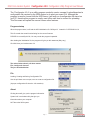
Program startup
When the program start, it will load the 2050 initialization file “2050sys.ini” located in C:\CPD2050\V4.0.9
This file contain the actual function listing for the current firmware
PLEASE do not modify this file, You may render the program inoperable.
After loading the initialization file, the program will give you this statement (May vary).
Click OK when you’ve taken note of it.
The main window show 3 pull-down menus.
File, Configure & Connect
They are described below.
File
Loading, Creating and Saving Configuration File
Use the pull down menu to open, save or create a configuration file.
(A proper configuration file has the .s19 extension).
About
Clicking about will give you the program information.
System info is a windows utility that give you
information about your computer.
NOT about the 2050 system.
Page 1
sonotechnique
2050 Comunication System Configurator 4.0.9 Configuration Utility Program User Manual
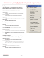
Configure
This is where you will go through each sub menu to define the
hardware that you have and also define the function(s) for each
switches, GPI, Events, etc
Here is an short explanation for the different sub menus.
Hardware setup.
Define the hardware that is installed on your 2050 system.
Automute / Mic Group.
Assignment of microphones for Studio, CRM & usage.
Signalizations.
Assignment of microphones for signalizations( ex: On air light)
Routing Setup.
Definitions of default bus monitoring.
Timer Setup.
Timer options configuration.
Midi Setup.
Configuration of the system Midi parameters.
Switches Programming.
This is where you assign functions to turret switches.
Remote Programming.
This is where you would assign functions to the remote switches.
Events Programming.
This is where you assign functions when define system events
occur.
Local Input Programming.
This is where you assign functions to the system GPI inputs.
The Main GPI & the first optional 2059 card (If present).
Optional GPI (65-128).
This is where you would assign functions to the other
Groups Programming.
If 4 functions per switch is not enough, you might want to use
Groups. Each of the 48 groups can hold another 4 functions.
Tallies (Auto).
Used to attach tallies to programmed switches.
DCA setup.
You assign volume control & define fixed level here.
sonotechnique
Page 2
2050 Comunication System Configurator 4.0.9 Configuration Utility Program User Manual
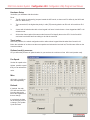
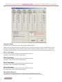
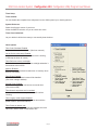
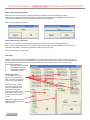
Hardware Setup
You define your hardware with this window.
Facts:
1The ID number is assigned by jumpers located the 2053 cards, so the turret ID is define by the 2053 card
that it is attached to).
2-
The Lowest the ID, the highest the priority in calls (TB) meaning that the an ID0 call will override an ID 3
call.
3-
A turret with 44 switches but with a timer keypad is in fact a 24 switch turret + timer keypad and NOT a 44
switches turret.
4-
All the other frame cards of the same model have an ID to identify them to the CPU. So the first 2054
card must have theID0 and has nothing to do with the turret ID0.
Turret setup.
Define the presence, the switch configuration with or without timer keypad & decide what Xbus Control it will
follow, the activation of an xbus mute the turret speaker and activate the local red led, The Xbus are define on the
Automute window.
Optional card(s) presence.
Let you define the presence of optional cards. As you see there is a minimum of one 2054 card (monitor card).
Fan Speed.
Set the fan speed at the
highest possible speed
that you can tolerate the
noise.
Misc.
All On tally = Any Mic on.
Well, self explanatory.
Refresh.
If checked, the main
CPU will send the DCA
& routing data to the
frame card regardless if
there a change.
If unchecked, the data
will be sent only if there
a change. (The update
Cycle time been
Page 3
sonotechnique
2050 Comunication System Configurator 4.0.9 Configuration Utility Program User Manual
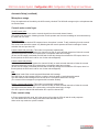
Automute Setup
You define your automatic mutes and some grouping with this window.
There is in fact 4 mute control signals, called Xbus 1 to 4. It is this mute control bus that is activated when one of
the define microphone(s) is ON. By default the 2054 card ID 0 Path A is attached to Xbus 1 and so on as shown.
The Optional 2054 cards ID 2 & 3 should be attached to one of those Xbus control line to be automatically muted.
Xbus 1 Automute.
You check the microphones that when ON will activate the Xbus 1.
(By default, it will mute the 2054 card ID0 path A).
Xbus 2 Automute.
You check the microphones that when ON will activate the Xbus 2.
(By default, it will mute the 2054 card ID0 path B).
Xbus 3 Automute.
You check the microphones that when ON will activate the Xbus 3.
(By default, it will mute the 2054 card ID1 path A).
Xbus 4 Automute.
You check the microphones that when ON will activate the Xbus 4.
(By default, it will mute the 2054 card ID1 path B).
Microphone Group A.
You may group microphones here to be used in the Mic group Mute/ON functions.
Although there is mention of more then one group, only Group A is presently available.
sonotechnique
Page 4
2050 Comunication System Configurator 4.0.9 Configuration Utility Program User Manual
Automute Setup (contitued)
Microphone usage.
Every microphones that is handle by the 2050 must by checked. The 2050 will manage only the microphones that
are checked here.
Console mute control type.
Via 2053 insert point.
The 2053 slate channel are used to mute the signal from the console channel inserts.
This mode is not interactive. Meaning that the console operator won’t have a knowledge of mutes activation by
the 2050 and vice versa.
Latched contacts.
The 2050 will activate latched GPI outputs when a microphone is muted. To tally monitoring from the console.
This mode is not interactive master only. Meaning that the console operator will have knowledge of mutes
activation but can’t put them ON.
Pulsed contact with mute tally. (This mode is not presently implemented)
Bidirectional mode. The 2050 monitor the channel mute tally on each selected channels to follow the console
operator and activate pulsed GPI outputs when a microphone state has to change.
(In fact, the GPI output is activated, the 2050 wait for the tally change then release the GPI output, there is a
timeout period, the 2050 won’t wait for ever for the acknowledgment).
Pulsed contact with ON tally.
Bidirectional mode. The 2050 monitor the channel ON tally on each selected channels to follow the console
operator and activate pulsed GPI outputs when a microphone state has to change.
(In fact, the GPI output is activated, the 2050 wait for the tally change then release the GPI output, there is a
timeout period, the 2050 won’t wait for ever for the acknowledgment).
Midi.
Bidirectional mode if the console support bidirectional midi message.
The 2050 listen to midi message from the console to track the state on each selected channels.
The 2050 transmit midi message to the console when a microphone state has to change.
(The content of the messages are programmable in another window)
Distinct contacts with ON tally. (This mode is not presently implemented)
Bidirectional mode. The 2050 monitor the channel ON tally on each selected channels to follow the console
operator and activate distinct GPI outputs when a microphone state has to change.
One GPI output for channel ON and another GPI output for channel OFF.
Pulse contact setup.
In Pluse contact with tally mode, this is the amount of time that the CPU will wait for a tally response.
70 is the default value. Don’t change this value unless directed to do so.
Other value may render the system unstable.
Page 5
sonotechnique
2050 Comunication System Configurator 4.0.9 Configuration Utility Program User Manual
Signalization Setup
You define your signalization options with this window.
Only The Auto ONAir 1 is directly attached to frame DB9 Sign connector.
The Other Auto ONAir will generate events that can be used to trigger other functions.
Those events programming are managed in the Event manager window.
Auto OnAir Light 1.
If any of the checked microphones is ON, The DB9 sign red light output will be activated.
An event will also be generated.
Auto OnAir Light 2 / 3 & 4.
If any of the checked microphones is ON, an event will be generated.
Options.
Enabled red light flashing.
The Red light output on the Sign. Connector will flash instead of bean solid.( Valid for OnAir 1 only)
Enabled auto green light.
With this option checked, the Green light output on the Sign. Connector will activate when the OnAir 1 is OFF.
Enabled flashing tallies when automated function are engaged.
With this option checked, If a equivalent function is programed on a turret switch, the tally of that switch will flash
If the automated version will engage. (Those functions includes the Onair signalizations and the monitor muting)
sonotechnique
Page 6
2050 Comunication System Configurator 4.0.9 Configuration Utility Program User Manual
Routing Setup
You define your power up default audio routing with this window.
For each monitoring, select the default source.
Ext A & Ext B are available for the 2054 cards only and only locally to the card itself.
2053 Slate Configuration.
Each present 2053 card can be either a slate channel or an external call in / external call out.
This is selected by the check box.
2053 ID8 & up are always programmed as slate channels.
Notes:
A slate channel represent that the input is always routed to the output and that you can TB to it.
The TB signal will mixed with the dimmed channel signal.
In external call in / external call out mode, the input is NOT routed to the output.
The external in signal is routed to programmed destination when the related function is activated.
The external call output generate the TB out signal when the related function is activated.
Slate Safety Control.
You can have a slate channel (If checked) to follow a master Enable/Disable Function. So when this function is disabled.
Pressing the slate key won’t have any effect. You can also decide what is the power up default.
Enabled is the factory default. This is available only on the first 8, 2053 cards slate channels.
Page 7
sonotechnique
2050 Comunication System Configurator 4.0.9 Configuration Utility Program User Manual
Timer Setup
Timer enabled.
You can disable the complete timer subsystem from the 2050 system by un checking this box
System Reference.
Select the reference source of your timer.
All but the SMPTE selection, let you to enter a time value.
Timer Clear Authorized.
Let you decide in which timer state you can actually clear the timer.
Other Options
Time Code Calculator Enabled.
Let you use the calculator function (See timer manual).
On the fly time value entry Enabled.
Let you use enter timer value even if the timer is running.
(It will stop the timer off course)
Timer Roll over to zero at midnight.
If checked the timer will pass to zero at midnight otherwise it
will continue with 24:00:00
Memory Enabled.
Time vale can be stored and recalled from 10 memory when
this box is checked.
Timer Event Enabled.
If checked the time related events will be handled.
(See event manager window).
Second Timer Enabled.
If checked the upper row can become a second timer.
(See timer manual).
Timer doesn’t stop when zero is reached.
If checked the timer won’t stop at zero, it will continue
counting
Timer Legacy mode support disabled.
If checked the timer value entry has to be done with the
preset function. (See timer manual)
Timer Preset on bottom row.
If checked and with the preset function engaged, the timer
Value entry will be shown on the bottom row.
sonotechnique
Page 8
2050 Comunication System Configurator 4.0.9 Configuration Utility Program User Manual
Midi Setup
With this window, you will define the content of the midi messages sent and receive to activate mute.
Note that those midi messages are manage only if the selected console type is midi.
You will also define the content of the midi user message.
Those message can be sent regardless of the console type.
So select the midi function that you want to program. Select the status byte, the midi channel, enter the desired
Value then click on load.(You must click load for each midi function)
If for all the Mic Mute/ON functions the inputs & outputs messages are the same please check the
“Mute inputs same as outputs” checkbox.
If possible you should configure your console not to send an echo of sent midi message.
If the console is sending and echo, please check the “Echo Compensation” checkbox.
Page 9
sonotechnique
2050 Comunication System Configurator 4.0.9 Configuration Utility Program User Manual
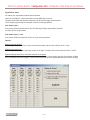
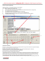
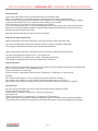
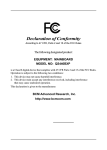
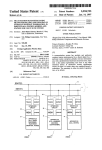
Switch Programming Manager
With this window, you will assign functions to turret switches.
Lets explain the sections of this window first.
1Click to select the turret that you want to program.
2Click to select the switch that you want to program.(The selected switch will be in a larger font).
3The available functions are listed here.
4The selected functions for the selected switch are listed here
5Click to Add or remove a function.(The function must be highlighted first)
6Each 2053 card has a GPI input that can be program like a switch with few exceptions.
7Load default timer functions.
1
3
4
7
5
2
6
Important Information
Because of memory limitation, the function list is limited to 256. So to get more functions, the system will employ
the main, second, third & fourth function system.
Example: in the function 187 (see above) the main function would be Monitoring Bus 1 Alternate,
the Second function {F2} would be monitoring Bus 1 Interlock
the third function {F3} would be Monitoring Bus 3 Alternate &
the Fourth {F4} would be monitoring Bus 3 Interlock.
To activate the second, you must have the “second function” function 255 just before the wanted function in the
selected functions list. This second function will rise a flag that the following function will clear after execution.
So if you want 2 consecutive second function, you must insert the function 255 twice just before each function.
To access the third function use function 253 and for the fourth function use function 254.
In the example above, the fourth function would be activated in this case because of the preceding function 254.
sonotechnique
Page 10
2050 Comunication System Configurator 4.0.9 Configuration Utility Program User Manual
Momentary, Alternate & Interlock functions
Momentary function are executed while the switch is pressed in case of turret switches, while the GPI input is
active in the case of local inputs or while the event is valid in the case of events.
Example : Function 051 “Microphone 1 Muted, Momentary”
Pressing the switch will muted the microphone, releasing it will unmute it.
Alternate functions are push ON/ push OFF functions, they are executed when pressing the switch once then
released when the switch is pressed again. Same with GPI inputs not really usable with events.
Example : Function 061 “Microphone 1 Muted, Alternate”
Pressing the switch once will muted the microphone, pressing the switch a second time will unmute it.
Interlock functions. You need a minimum of 2 switches to implement the interlock functions. It means that a
switch is program to activate a function and another switch is program to deactivate it or activate something else.
Example 1:
Switch A program with Function 071 “Microphone 1 Muted, Interlock”
Switch B program with Function 081 “Microphone 1 ON, Interlock”
Pressing the switch A will muted the microphone, pressing the switch B will unmute it.
Example 2: (this example also show the second & fourth function usage
Switch A program with Function 255 “F2” + Function 207
“Card 2054 ID0 Path A Monitoring Bus 1 Alternate / F2 {Bus 1 Interlock} / F3 {Bus 3 alt} / F4 {Bus 3 Interlock}”
Pressing this switch will activate Monitoring of Bus 1
Switch B program with Function 255 “F2” + Function 208
Card 2054 ID0 Path A Monitoring Bus 2 Alternate / F2 {Bus 2 Interlock} / F3 {Bus 4 alt} / F4 {Bus 4 Interlock}”
Pressing this switch will activate Monitoring of Bus 2
Switch C program with Function 254 “F4” + Function 207
“Card 2054 ID0 Path A Monitoring Bus 1 Alternate / F2 {Bus 1 Interlock} / F3 {Bus 3 alt} / F4 {Bus 3 Interlock}”
Pressing this switch will activate Monitoring of Bus 3
Switch D program with Function 254 “F4” + Function 208
Card 2054 ID0 Path A Monitoring Bus 2 Alternate / F2 {Bus 2 Interlock} / F3 {Bus 4 alt} / F4 {Bus 4 Interlock}”
Pressing this switch will activate Monitoring of Bus 4
Switch E program with Function 255 “F2” + Function 209
“Card 2054 ID0 Path A Monitoring Ext A Alternate / F2 {Ext A Interlock} / F3 {Ext B alt} / F4 {Ext B Interlock}”
Pressing this switch will activate Monitoring of External A
Switch F program with Function 254 “F4” + Function 209
“Card 2054 ID0 Path A Monitoring Ext A Alternate / F2 {Ext A Interlock} / F3 {Ext B alt} / F4 {Ext B Interlock}”
Pressing this switch will activate Monitoring of External B
Individual vs All Functions restriction.
Some function are available in individual form or ALL form. Example:
The function 061 “Microphone 1 Muted, Alternate” can be programmed on a switch on a guest turret switch while
the function 069 “All Microphones Muted, Alternate” can be programmed on the host turret.
In this case it will work. The guest can put his microphone on or off. But the host will override the selection if he
presses the all microphone on/off function.
Exception for monitoring functions.
In the case of monitoring selection, it would not work. The All function will take precedence all the time over
individual selection.
Page 11
sonotechnique
2050 Comunication System Configurator 4.0.9 Configuration Utility Program User Manual
Group Function.
As you have notice there is only 4 functions that can be executed per switch.
Well, it’s not exactly true. If you need more then 4 functions you can use the grouped functions.
There are 48 of those groups which have their content program in the “group programming manager” window
A group function take the room of 1 function but could contain up to 4 functions.
So it means that you could have 16 functions program to one switch.
In fact, you could go higher then 16 since you can program groups within groups, but it would become hard to
follow and can cause a software feedback (A group function programmed with another group function that is
already programmed with the first group).
Note that functions within groups may not activate their tallies.
External Call Input programming.
When programming a GPI input to activate a call from the external world via the 2051 card.
You must first program the function 026 “External In (2051) is calling, Followed by destination”
Then program a standard call function which represent the destination.
When programming a GPI input to activate a call from the external world via the 2053 ID0 card.
You must first program the function 252 “F2” + the function 027
“Calling Slate 2053 ID0 / F2{ External in is calling, Followed by destination}”
Then program a standard call function which represent the destination.
Dummy functions.
When a function doesn’t generate a tally, like the call functions, you can manage to transfer tally information with
the use of dummy functions. It is a flashing tally only
There are 4 of those in function 252
“Dummy Function 1, Momentary (Tally will flash) / F2{Dummy 2} / F3{Dummy 3} / F4{Dummy 4}”
Example:
On a switch on the producer 1 turret, you program the function call host + Dummy 1
On a switch on the producer 2 turret, you also program the function call host + Dummy 1
When either of the producers is calling the host, the corresponding switch on the other turret will flash.
Dummy events.
You can’t get tally information out via GPI output unless their function generate an event.
For that purpose the function 246
“Dummy event 1, Alternate / F2{event 2} / F3{event 3} / F4{event 4}”
and function 247
“Dummy event Interlock 1 / F2{Interlock 2} / F3{Interlock 3} / F4{Interlock 4}”
where created to be programmed in addition to existing functions to activate Dummy events when activated.
Those Dummy Events can then be programmed to activate GPI outputs in the events programming manager.
sonotechnique
Page 12
2050 Comunication System Configurator 4.0.9 Configuration Utility Program User Manual
Remote Programming Manager.
This windows is not presently available since the remote turret is not presently available.
Events Programming Manager.
This windows is use to program function when certain events occurs.
The events listing is self explanatory.
Select one by clicking on it, then select the desired function(s).
Page 13
sonotechnique
2050 Comunication System Configurator 4.0.9 Configuration Utility Program User Manual
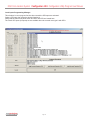
Local Inputs Programming Manager.
This windows is use to program function when certain the GPI Inputs are activated.
Select a GPI input, then select the desired function(s).
Notice that the frame front panel switch and 2051 card GPI are located here.
The First 8 GPI Inputs (& outputs) are not available when the console mute type is with GPI’s
sonotechnique
Page 14
2050 Comunication System Configurator 4.0.9 Configuration Utility Program User Manual
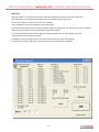
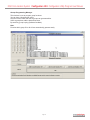
Groups Programming Manager.
This windows is use to program group functions.
You can have 4 functions per group.
Only the function within the first 12 groups can generate tallies.
Select a group then add the desired functions.
By careful by group looping (Software feedback)
Note:
Function within group 25 to 48 will not automatically generate a tally.
Page 15
sonotechnique
2050 Comunication System Configurator 4.0.9 Configuration Utility Program User Manual
Tallies programming (automatic).
Each time you close the Turret or group programming windows you have the following windows.
This is a sub program that will look into each programmed switch and assign the related tally in a table. This
information is needed by the 2050 to generate the tallies at the right place.
Click Go to proceed then click Done.
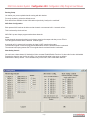
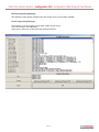
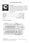
DCA Setup.
There is a lot of DCA (Digital Control Amplifier) in the 2050 system. Each of them can be control by 4 type of
Controller. The first are the turret potentiometers, second are the 2050 chassis front panel potentiometers, third
are fixed value determined once via this program and fourth is no control at all, the DCA will be muted.
This window elements are
1The DCA that be controlled.
2The possible controller.
3Potentiometer selection.
4Fixed value selector.
Fixed value notes:
The Hexadecimal value is
shown on the bottom of the
fader. The value in decibel is
shown in the green window.
For DCA that are used for
Trim & Dim, the trim value
must be considered when
selecting the dim value.
Example: if the 2053 aux in
level is set to -6db, for a dim
of -15 db you would select
-21db.
1
3
2
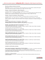
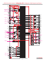
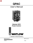
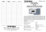
On the next page you will the
2050 Block diagram with the
4
DCAs location.
sonotechnique
Page 16
2050 Comunication System Configurator 4.0.9 Configuration Utility Program User Manual
Control Bus
Stereo bus 4
Stereo bus 3
Stereo bus 2
Stereo bus 1
DCA
Stereo Mix bus 4
1
Stereo Mix bus 3
TB
Mic
Power
Routing
Stereo Mix bus 2
Level
Call bus 2
TX
Call bus 1
Control
1
Stereo Mix bus 1
RX
Rs485
Tx
Call Mix bus 2
2
1
Call Mix bus 1
2053 Mic Level
Turret Phone
DCA
2053 Trim Level
2053 Dim Level
Turret
Power
Rs485
Rx
Side tone
enable
Main
Phones
Dim/
Split
DCA
1
DB25
Connector
N/C
1
2053 Call Level
1
Analog Slate/Call
Input 1
1
Analog Slate/Call
Output 1
1
Analog Slate/Call
Input 2
1
Analog Slate/Call
Output 2
1
Analog Slate/Call
Input 3
1
Analog Slate/Call
Output 3
1
Analog Slate/Call
Input 4
1
Analog Slate/Call
Output 4
Dim
TB
Speaker
Turret Speaker
DCA
DCA
1 GPI/
1 GPO
2053 Aux In
Level
2053 Slate
Dim Level
Slate
enable
DCA
DCA
1
Control
Dim
Slate in/
Ext call in
1
Slate
enable
DCA
Dim
DB9
Connector
Slate out/
Ext call out
DB25
Connector
Slate
enable
1
2053 Call Out
Level
DCA
Dim
Slate
enable
1 of possible 16
2053 Turret audio card + Slate I/O
Control
Routing
Level
Monitor A
(L&R) Inputs
Dim
2
Slate
enable
Monitor B
(L&R) Inputs
2
Routing
2054 Trim
Level
2054 Dim
Level
2054 Monitor
A DCA
Routing
DCA
2
Dim/
Trim
DCA
2054 Call
Level
DB9
Connector
2057 Quad Slate/Call card
1 of possible 4 “Option”
4
Headphones
Level Controls
1
Headphones
Output 1
Level
DCA
2056 Call
Level
DCA
Dim/
Trim
Dim
2054 Monitor
B DCA
Control
4 GPI/
4 GPO
Level
Dim
DB25
Connector
Monitor A
(L&R) Outputs
Control
Monitor B
(L&R) Outputs
DCA
2
DCA
1
DB25
Connector
DCA
DCA
1 of possible 4
2054 Monitor card
Level
Dim/
Trim
Control
DCA
1
Routing
2051 Master
Call Bus 1
Headphones
Output 2
DCA
Headphones
Output 3
2056 Trim
& Dim Level
Caller 1 Level
Dim/
Trim
DCA
1
Headphones
Output 4
2056 Quad Headphones Amp card
1 of possible 4 “Option”
Stereo Input
Bus 1
2
Stereo output
Bus 2
2
DB25
Connector
2051 Ext in
Level
2051 Ext out
Level
Stereo Input
Bus 3
2
Stereo Input
Bus 4
2
Ext call in
1
DCA
DB9
Connector
Ext call out
1 GPI/
1 GPO
1
DCA
Control
2051 Mix Bus card
Part of 2050 Base system
Audio Block Diagram
Page 17
sonotechnique
2050 Comunication System Configurator 4.0.9 Configuration Utility Program User Manual
Manual Programming Menu
This menu us used for manual switches and tallies programming. (Not available)
At this point, you should save your work
Click on Save as from the File Pull Down Menu
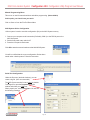
2050 System Online Configuration
Online system is used to send the configuration (file) to the 2050 System memory
1. Connect your computer serial connection (Preferably COM 1) to the RS232 port on the
2050 front panel.
2. Set the front panel rotary switch to F
3. Press the front panel reset button
Click GO to start the communication terminal with 2050 System.
You will be notified that the current configuration file has been
saved under a backup name. Follow the instruction.
Serial Port Configuration
Under the file menu (terminal windows), you can
create a log file. (Not recommended)
The 2050 System terminal is set to com1 by default.
To change this, open the Properties dialogue
window and select your COM port.
When properly set, click on Port Open. You will see
the following message.
sonotechnique
Page 18
2050 Comunication System Configurator 4.0.9 Configuration Utility Program User Manual
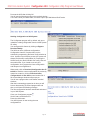
Do reset the 2050 after clicking OK.
You will see the following prompt on the terminal window.
If You don’t check your serial cable, it must be a pin to pin Db9 Male to Db9 Female.
Sending Configuration to 2050 System
The Configurator program will, by default, ask you to
upload the existing configuration from the 2050 System
for safety.
You can bypass this feature by clicking on Bypass
Download Safety.
The 2050 can store 2 different configurations.
Configuration A and B. If required they can be
activated by programming the frame config switches to
do so. At power up or following a reset. the system will
always load the main configuration (A). Pressing the
Switch Config A or B will load this new config. Note a 3
seconds timeout. If you intend to use only one
configuration, don’t program the frame config switch
and always use configuration A.
When ready, click on Download Configuration A or B
to 2050 to send the current configuration file previously
opened or created, or click on Download other
configuration A or B to 2050 to send another file. A
file access dialogue windows will prompt you.
You will see a progress bar on the bottom terminal
windows.
After the incrementing progress bar is done you will
have a decrementing 30 second progress bar and
then you will have the following message.
The new configuration has been transferred and saved
in your 2050 System.
Close your Configurator program .
Set the rotary switch back to 0.
Press the reset button.
Your 2050 System is now running the new
configuration A.
Page 19
sonotechnique
2050 Comunication System Configurator 4.0.9 Configuration Utility Program User Manual
Sending New Firmware to 2050 System
You may have to upgrade your 2050 firmware in the future to get more features.
Here are the steps.
Click on the firmware access menu.
You will be asked to type in the access code. (The access code is cpd2050 in lower case ).
The Configurator program will by default ask you to upload the existing firmware from the
2050 system for safety.
You can bypass this feature by clicking on Bypass Download Safety.
When ready, click on Download new firmware to 2050 to send
the new firmware. A file access dialogue windows will prompt you.
You will see a progress bar on the bottom terminal windows.
After few minutes you will have the following message.
The new firmware has been transferred in your 2050 System.
You can close your Configurator program at this point.
Set the rotary switch back to 0 on the 2050.
Press the reset button on the 2050.
Your 2050 System is now running with the new firmware.
Request existing Firmware version
To know what firmware version you presently running. Click on Firmware version ?
You will see the program header with the firmware revision.
sonotechnique
Page 20
2050 Comunication System Configurator 4.0.9 Configuration Utility Program User Manual
NOTES
Page 21
sonotechnique
2050 Comunication System Configurator 4.0.9 Configuration Utility Program User Manual
All requests and comments should be sent to:
Paul Delisle
Technical Director
Sonotechnique PJL Inc.
200 Gince Street
St. Laurent, Québec Canada H4N 2W6
Tel.: (514) 332-6868 ext. 230
Fax: (514) 332-5537
eM: [email protected]
Other locations
248 The Esplanade
Toronto, Ontario Canada M5A 4J6
Tel.: (416) 947-9112
Toll Free: 800-449-5919
eM: [email protected]
4001 2nd Avenue
Burnaby, BC Canada V5C 3X1
Tel.: (604) 298-2200
Fax: (604) 298-2274
eM: [email protected]
Http://www.sonotechnique.ca
All rights reserved