1
Autodesk NavisWorks Manage 2009
User Manual
Autodesk, Inc.
Autodesk NavisWorks Manage 2009: User Manual
Autodesk, Inc.
Copyright © 2007 Autodesk, Inc.
Revision 6.1.46140
Autodesk, Inc. reserves the right to make changes in specification at any time and without notice. The information furnished by
Autodesk, Inc. in this publication is believed to be accurate; however, no responsibility is assumed for its use, nor for any
infringement of patents or other rights of third parties resulting from its use.
Autodesk, NavisWorks, AutoCAD, Revit, Inventor, and 3ds Max are registered trademarks or trademarks of Autodesk, Inc. All other
brand names, product names or trademarks belong to their respective holders. All rights reserved.
LightWorks, the LightWorks logo, LWA and LWA-Enabled are registered trademarks of LightWork Design Ltd. The LWA-Enabled
logo, Interactive Image Regeneration, IIR, A-Cubed, Feature-Following Anti-Aliasing and FFAA are all trademarks of LightWork
Design Ltd. All other trademarks, images and logos remain the property of their respective owners. Copyright of LightWork Design
Ltd. 1990-2006, 2007.
This software is based in part on the work of the Independent JPEG Group.
Contains a modified version of Open CASCADE libraries. See the license file "OpenCascadeLicense.txt" in the NavisWorks
installation directory. Source code is available from download.autodesk.com/us/navisworks/OpenCascade.zip.
Contents
Part 1. Welcome to Autodesk NavisWorks Manage 2009 ............................................................... 1
Chapter 1. Autodesk NavisWorks Manage 2009 Readme ....................................................... 2
Installing Autodesk NavisWorks Manage 2009 ............................................................... 2
Customer Involvement Program ....................................................................................2
Product Notes .............................................................................................................3
Autodesk Freedom ......................................................................................................3
Resources ...................................................................................................................3
Known Problems in Autodesk NavisWorks Manage 2009 ............................................... 4
Credits ........................................................................................................................4
Chapter 2. New Features ..................................................................................................... 5
Part 2. Installation ........................................................................................................................7
Chapter 3. Quick Start to Stand-Alone Installation .................................................................. 8
How to Prepare for Installation ...................................................................................... 8
How to Review System Requirements ................................................................... 8
How to Understand Administrative Permission Requirements ................................. 8
How to Install Multiple or Bundled Products ........................................................... 8
How to Locate Your Autodesk NavisWorks Manage 2009 Serial Number ................ 8
How to Avoid Data Loss During Installation ........................................................... 9
How to Install and Run Autodesk NavisWorks Manage 2009 .......................................... 9
How to Install Autodesk NavisWorks Manage 2009 ................................................ 9
How to Register and Activate NavisWorks ............................................................. 9
How to Launch NavisWorks .................................................................................. 10
How to Launch NavisWorks in Another Language .................................................. 10
Chapter 4. Move to NavisWorks from a Previous Release ...................................................... 11
Chapter 5. Install NavisWorks for an Individual User .............................................................. 12
The NavisWorks Installation Wizard .............................................................................. 12
System Requirements ..................................................................................................12
Install NavisWorks .......................................................................................................13
Register and Activate NavisWorks ................................................................................ 16
Add or Remove Features ............................................................................................. 17
Reinstall or Repair Autodesk NavisWorks Manage 2009 ................................................ 17
Uninstall Autodesk NavisWorks Manage 2009 ............................................................... 18
Chapter 6. Install NavisWorks for Multiple Users .................................................................... 20
Quick Start to Network Installation ................................................................................ 20
How to Prepare for Deployment ............................................................................ 20
How to Set Up a License Server ........................................................................... 21
How to Set Up and Distribute the Program ............................................................ 25
System Requirements for a Deployment ....................................................................... 28
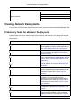
Creating Network Deployments ....................................................................................30
Preliminary Tasks for a Network Deployment ......................................................... 30
Use the Installation Wizard to Set Up a Deployment ............................................... 32
Point Users to the Administrative Image ................................................................ 39
Uninstall the Program ...........................................................................................40
Chapter 7. Installation Troubleshooting ................................................................................. 41
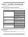
What are the minimum system requirements? ............................................................... 41
How can I check my graphics card driver to see if it needs to be updated? ...................... 41
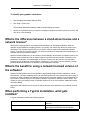
What is the difference between a stand-alone license and a network license? ................. 42
What is the benefit to using a network licensed version of the software? .......................... 42
When performing a Typical installation, what gets installed? ........................................... 42
Where are my product manuals? .................................................................................. 43
Deployment Issues ......................................................................................................43
iv
Autodesk NavisWorks Manage 2009
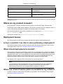
Is there a checklist I can refer to when performing a deployment? ........................... 43
Where should deployments be located? ................................................................ 43
Where can I check if service packs are available for my software? .......................... 43
Networking Issues .......................................................................................................44
Where do I find my server name? ......................................................................... 44
If I choose to create a log file, what kind of information does the log file contain? ..... 44
Maintenance Issues .....................................................................................................44
Is it possible to change the installation folder when adding or removing features? .... 44
When should I reinstall the product instead of a repair? .......................................... 44
Do I need my original disk to reinstall my software? ............................................... 44
When I uninstall my software, what files are left on my system? .............................. 44
Part 3. Basic NavisWorks Functionality ......................................................................................... 46
Chapter 8. Overview ............................................................................................................47
Chapter 9. File Management ................................................................................................ 48
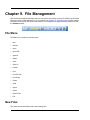
File Menu ....................................................................................................................48
New Files ....................................................................................................................48
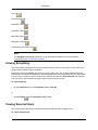
Refreshing Files ..........................................................................................................49
Opening Files ..............................................................................................................49
Opening Files via URL ................................................................................................. 50
Appending Files ...........................................................................................................50
Merging Files ...............................................................................................................51
Saving Files ................................................................................................................51
Saving and Renaming Files .......................................................................................... 52
Publishing Files ...........................................................................................................52
Printing .......................................................................................................................52
Printing the Current Viewpoint .............................................................................. 52
Previewing Printouts ............................................................................................53
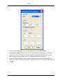
Setting up printouts ..............................................................................................53
Deleting Files ..............................................................................................................54
Emailing Files ..............................................................................................................54
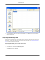
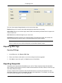
Importing Files .............................................................................................................55
Importing PDS Tags .............................................................................................55
Importing PDS Display Sets ................................................................................. 56
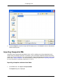
Importing Viewpoints XML ....................................................................................57
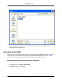
Importing Search XML .........................................................................................58
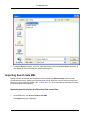
Importing Search Sets XML .................................................................................. 59
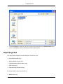
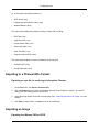
Exporting Files .............................................................................................................60
Exporting to a Piranesi EPix Format ...................................................................... 61
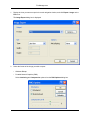
Exporting an Image ..............................................................................................61
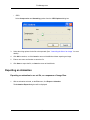
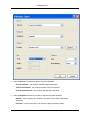
Exporting an Animation ........................................................................................63
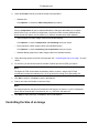
Controlling the Size of an Image ........................................................................... 65
Exporting PDS Tags ............................................................................................66
Exporting Viewpoints ...........................................................................................66
Exporting Current Search .....................................................................................67
Exporting Search Sets .........................................................................................67
Exporting Viewpoints Report .................................................................................67
Exporting to Autodesk DWF ................................................................................. 68
Exporting to Google Earth KML ............................................................................ 68
Quitting NavisWorks ....................................................................................................71
Chapter 10. Converting Files ................................................................................................ 72
File Readers ................................................................................................................72
NWF Files ...........................................................................................................73
NWD Files ...........................................................................................................73
NWC Files ...........................................................................................................74
DWG and DXF Files ............................................................................................ 76
DWF Files ...........................................................................................................80
Bentley AutoPLANT Files .....................................................................................82
v
Autodesk NavisWorks Manage 2009
3DS Files ............................................................................................................84
DGN and PRP Files ............................................................................................. 85
MAN Files ...........................................................................................................88
PDS Files ............................................................................................................90
IGES Files ...........................................................................................................91
STEP Files ..........................................................................................................93
Inventor Files .......................................................................................................95
VRML world files ..................................................................................................96
Riegl Scan Files ..................................................................................................98
Faro Scan Files ...................................................................................................100
Leica Scan Files ..................................................................................................101
Z+F Scan Files ....................................................................................................102
ASCII Laser Scan Files ........................................................................................ 104
STL Stereolithography files ...................................................................................105
AVEVA Review RVM and RVS files ...................................................................... 106
IFC files ..............................................................................................................109
Sketchup SKP files ..............................................................................................111
File Exporters ..............................................................................................................113
AutoCAD .nwc Exporter .......................................................................................114
Revit .nwc Exporter ..............................................................................................116
MicroStation .nwc Exporter ...................................................................................119
Viz and Max .nwc Exporter ................................................................................... 121
ArchiCAD .nwc Exporter .......................................................................................125
CAD Previewing ..........................................................................................................127
NavisWorks Navigator for AutoCAD ...................................................................... 127
Chapter 11. Publishing .........................................................................................................129
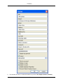
Publishing from NavisWorks .........................................................................................129
Publishing from AutoCAD .............................................................................................131
Publishing from MicroStation ........................................................................................132
Freedom .....................................................................................................................134
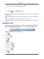
Chapter 12. Navigating ........................................................................................................139
Navigation Modes ........................................................................................................139
Walking ...............................................................................................................140
Looking Around ...................................................................................................140
Zooming ..............................................................................................................141
Zooming to a Box ................................................................................................ 141
Panning ..............................................................................................................142
Orbiting ...............................................................................................................142
Examining ...........................................................................................................142
Flying ..................................................................................................................143
Spinning on a Turntable ....................................................................................... 143
Navigation Tools ..........................................................................................................144
Viewing Everything ..............................................................................................145
Viewing Selected Items ........................................................................................145
Focusing .............................................................................................................146
Perspective Camera ............................................................................................146
Orthographic Camera ...........................................................................................146
Collision Detection ...............................................................................................147
Gravity ................................................................................................................148
Crouching ...........................................................................................................149
Third Person View ...............................................................................................149
Preset Viewpoints ................................................................................................150
Straighten ...........................................................................................................151
Set World Up .......................................................................................................151
Camera Tilt .................................................................................................................152
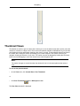
Thumbnail Views .........................................................................................................153
Using a SpaceBall .......................................................................................................155
vi
Autodesk NavisWorks Manage 2009
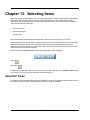
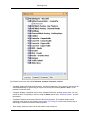
Chapter 13. Selecting Items ................................................................................................. 157
Selection Trees ...........................................................................................................157
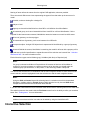
Interactive Selection .....................................................................................................159
Select Mode ........................................................................................................160
Select Box Mode .................................................................................................160
Selection Commands ...........................................................................................161
Selection and Search Sets ........................................................................................... 162
Saving Selection and Search Sets ........................................................................ 162
Recalling Selection and Search Sets ..................................................................... 163
Managing Selection Sets ......................................................................................163
Selection Resolution ....................................................................................................165
Selection Options ........................................................................................................166
Chapter 14. Finding .............................................................................................................168
Properties ...................................................................................................................168
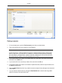
Finding Items ...............................................................................................................169
Quick Find ...................................................................................................................171
Finding Comments .......................................................................................................172
Chapter 15. Editing ..............................................................................................................175
Holding and releasing objects ....................................................................................... 175
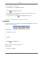
Undo/Redo ..................................................................................................................176
Hiding Items ................................................................................................................178
Making items required ..................................................................................................178
Hiding Unselected Items ..............................................................................................178
Overriding Item Properties ............................................................................................179
Overriding Color ..................................................................................................179
Overriding Transparency ......................................................................................179
Overriding Transforms .........................................................................................180
Overriding Hyperlinks ...........................................................................................181
Resetting Overriden Properties .....................................................................................181
Resetting Colors and Transparencies .................................................................... 181
Resetting Hyperlinks ............................................................................................181
Resetting Items' Positions ....................................................................................181
Resetting All Overriden Properties ................................................................................ 182
Resetting All Colors and Transparencies ............................................................... 182
Resetting All Items' Hyperlinks .............................................................................. 182
Revealing All Items ..............................................................................................182
Making All Items Unrequired ................................................................................. 182
Resetting All Items' Positions ................................................................................ 183
Custom Properties .......................................................................................................183
Add User Data Tab .............................................................................................. 183
Rename User Data Tab ....................................................................................... 183
Add New Property ................................................................................................184
Edit Property Value ..............................................................................................184
Rename Property ................................................................................................185
Delete Property ...................................................................................................185
Delete User Data Tab .......................................................................................... 185
Setting a File's Units and Transform .............................................................................. 186
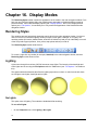
Chapter 16. Display Modes .................................................................................................. 188
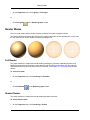
Rendering Styles .........................................................................................................188
Lighting ...............................................................................................................188
Render Modes .....................................................................................................193
Display Primitives ................................................................................................194
Background Color ................................................................................................196
Culling Options ............................................................................................................196
Orientation Options ......................................................................................................198
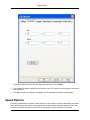
Speed Options .............................................................................................................199
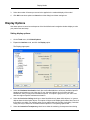
Display Options ...........................................................................................................201
vii
Autodesk NavisWorks Manage 2009
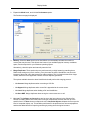
Performance Options ...................................................................................................202
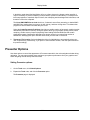
Presenter Options ........................................................................................................204
Chapter 17. Viewpoints ........................................................................................................207
Saving Viewpoints .......................................................................................................207
Recalling Viewpoints ....................................................................................................207
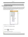
The Viewpoints Control Bar .......................................................................................... 208
The Viewpoint Shortcut Menus ..................................................................................... 209
The Viewpoints Control Bar Shorcut Menu ............................................................ 209
Viewpoints ..........................................................................................................210
Viewpoint Animations ...........................................................................................210
Folders ...............................................................................................................211
Editing Viewpoints .......................................................................................................211
Viewpoints Options ......................................................................................................214
Chapter 18. Sectioning .........................................................................................................218
Sectioning a model ......................................................................................................218
Linking Sections ..........................................................................................................220
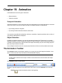
Chapter 19. Animation .........................................................................................................222
The Animation Toolbar .................................................................................................222
The Viewpoints Control Bar .......................................................................................... 223
Creating Viewpoint Animations .....................................................................................224
Editing Viewpoint Animations ........................................................................................225
Animation Cuts ............................................................................................................226
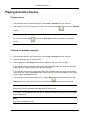
Playing Back Animations ..............................................................................................226
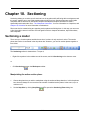
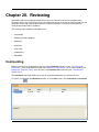
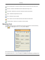
Chapter 20. Reviewing .........................................................................................................228
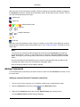
Commenting ................................................................................................................228
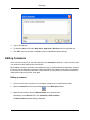
Adding Comments ...............................................................................................229
Editing Comments ...............................................................................................231
Deleting Comments .............................................................................................232
Redlining .....................................................................................................................233
Adding Redlines ..................................................................................................233
Adding Redline Tags ............................................................................................235
Finding Redline Tags ...........................................................................................236
Editing Redline Tags ............................................................................................237
Measuring ...................................................................................................................237
Measuring Tools ..................................................................................................238
Snapping ............................................................................................................240
Transforming Objects ...........................................................................................241
Measure Options .................................................................................................243
Hyperlinks ...................................................................................................................244
Adding Hyperlinks ................................................................................................245
Displaying Hyperlinks ...........................................................................................246
Following Hyperlinks ............................................................................................247
Editing Hyperlinks ................................................................................................247
Deleting Hyperlinks ..............................................................................................249
Hyperlinks Options ...............................................................................................250
Smart Tags .................................................................................................................254
Smart Tags Options .............................................................................................254
Collaboration ...............................................................................................................257
SwitchBack .................................................................................................................260
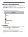
Chapter 21. Object Manipulation ........................................................................................... 262
Using Snapping ...........................................................................................................262
Highlighting Objects .....................................................................................................263
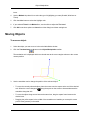
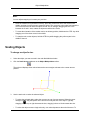
Moving Objects ............................................................................................................265
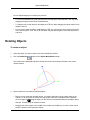
Rotating Objects ..........................................................................................................266
Scaling Objects ...........................................................................................................267
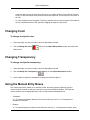
Changing Color ...........................................................................................................268
Changing Transparency ...............................................................................................268
viii
Autodesk NavisWorks Manage 2009
Using the Manual Entry Boxes ...................................................................................... 268
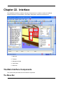
Chapter 22. Interface ...........................................................................................................270
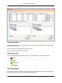
The Main Interface Components ................................................................................... 270
The Menu Bar .....................................................................................................270
The Toolbars .......................................................................................................271
The Main Navigation Window ............................................................................... 272
The Control Bars .................................................................................................272
The Status Bar ....................................................................................................273
View Menu ..................................................................................................................274
Control Bars ........................................................................................................275
Workspaces ........................................................................................................275
Customizing Toolbars ..........................................................................................277
Workspace Toolbar ..............................................................................................284
Customizing the Main Window .............................................................................. 285
Stereo Rendering ................................................................................................288
Scene Statistics ...................................................................................................289
Units ...........................................................................................................................290
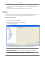
Profiles .......................................................................................................................291
Search Directories .......................................................................................................292
Chapter 23. Tools ................................................................................................................293
Comparing Models .......................................................................................................293
Chapter 24. Options .............................................................................................................296
File Options .................................................................................................................296
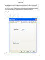
Location Options ..........................................................................................................296
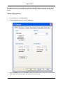
Environment Options ...................................................................................................297
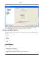
Global Options .............................................................................................................298
Configuring Global Options ...................................................................................299
Importing and Exporting Global Options ................................................................ 301
Chapter 25. DataTools .........................................................................................................305
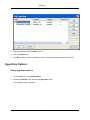
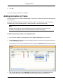
Adding Database Links ................................................................................................305
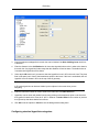
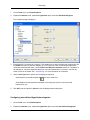
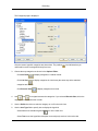
Configuring Database Links ..........................................................................................307
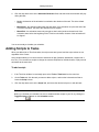
Managing Database Links ............................................................................................310
Full Tag List ................................................................................................................314
Chapter 26. Getting Help ...................................................................................................... 317
Help Topics .................................................................................................................317
What's This? ...............................................................................................................318
NavisWorks on the Web ............................................................................................... 318
License .......................................................................................................................319
Customer Involvement Program ....................................................................................321
System Info .................................................................................................................322
About NavisWorks .......................................................................................................322
Part 4. Using Presenter ................................................................................................................ 324
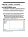
Chapter 27. Overview of Presenter ....................................................................................... 325
Working with the Presenter Window .............................................................................. 325
The Rendering Style Toolbar ........................................................................................ 326
Using the Presenter Archives ....................................................................................... 326
The User Archive .................................................................................................327
Additional Archives ..............................................................................................327
Chapter 28. Rendering Scenes ............................................................................................. 329
Setting Up And Rendering A Scene .............................................................................. 329
Exporting Rendered Output ..........................................................................................329
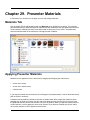
Chapter 29. Presenter Materials ........................................................................................... 333
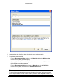
Materials Tab ..............................................................................................................333
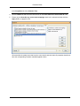
Applying Presenter Materials ........................................................................................333
Removing Presenter Materials ......................................................................................334
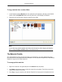
Organizing and Managing Materials .............................................................................. 335
Editing Presenter Materials ...........................................................................................337
ix
Autodesk NavisWorks Manage 2009
Advanced Materials .....................................................................................................341
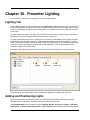
Chapter 30. Presenter Lighting ............................................................................................. 344
Lighting Tab ................................................................................................................344
Adding and Positioning Lights ....................................................................................... 344
Organizing and Managing Lights ................................................................................... 346
Editing Lights ...............................................................................................................348
Shadow Casting ..........................................................................................................351
Advanced Lighting .......................................................................................................352
Soft Shadows ......................................................................................................352
Physically Accurate Lights ....................................................................................352
Volumetric Lights .................................................................................................353
Image-based Lighting ...........................................................................................353
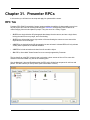
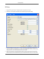
Chapter 31. Presenter RPCs ................................................................................................ 356
RPC Tab .....................................................................................................................356
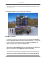
Chapter 32. Rendering Effects .............................................................................................. 360
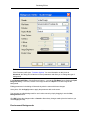
Effects Tab ..................................................................................................................360
Background Effects ......................................................................................................360
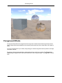
Foreground Effects ......................................................................................................363
Chapter 33. Rendering Styles ............................................................................................... 365
Rendering Tab .............................................................................................................365
Rendering Styles .........................................................................................................365
Predefined Rendering Styles ........................................................................................366
Auto Exposure .............................................................................................................367
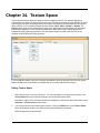
Chapter 34. Texture Space ................................................................................................... 369
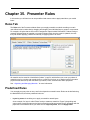
Chapter 35. Presenter Rules ................................................................................................ 372
Rules Tab ...................................................................................................................372
Predefined Rules .........................................................................................................372
Custom Rules ..............................................................................................................373
Applying Presenter Rules .............................................................................................375
The Presenter Rules Example ...................................................................................... 375
Part 5. Object Animation .............................................................................................................. 379
Chapter 36. Overview ..........................................................................................................380
Basic terminology ........................................................................................................380
Scope .........................................................................................................................380
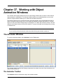
Chapter 37. Working with Object Animation Windows ............................................................ 382
The Animator Window ..................................................................................................382
The Animator Toolbar ..........................................................................................382
The Scene View ..................................................................................................384
The Timeline View ...............................................................................................386
The Manual Entry Bar .......................................................................................... 388
The Scripter Window ....................................................................................................389
The Script View ...................................................................................................390
The Event View ...................................................................................................392
The Action View ..................................................................................................393
The Properties View .............................................................................................395
Chapter 38. Creating Animations .......................................................................................... 397
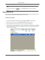
Animation Scenes ........................................................................................................397
Adding Scenes ....................................................................................................397
Deleting Scenes ..................................................................................................397
Organizing Scenes ..............................................................................................398
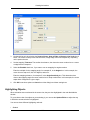
Animation Sets ............................................................................................................399
Adding Animation Sets .........................................................................................399
Updating Animation Sets ......................................................................................400
Manipulating Geometry Objects ............................................................................401
Cameras .....................................................................................................................410
Adding Cameras ..................................................................................................410
Manipulating Camera Viewpoints ..........................................................................411
x
Autodesk NavisWorks Manage 2009
Section Plane Set ........................................................................................................411
Adding Section Plane Sets ................................................................................... 411
Manipulating Sectional Cuts .................................................................................411
Keyframes ...................................................................................................................412
Capturing Keyframes ...........................................................................................412
Editing Keyframes ................................................................................................413
Playing Animation Scenes ............................................................................................417
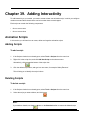
Chapter 39. Adding Interactivity ............................................................................................ 418
Animation Scripts .........................................................................................................418
Adding Scripts .....................................................................................................418
Deleting Scripts ...................................................................................................418
Organizing Scripts ...............................................................................................419
Events ........................................................................................................................419
Adding Events .....................................................................................................420
Testing Events .....................................................................................................420
Configuring Events ..............................................................................................420
Actions ........................................................................................................................424
Adding Actions ....................................................................................................424
Testing Actions ....................................................................................................424
Configuring Actions ..............................................................................................424
Enabling Scripting ........................................................................................................429
Chapter 40. Animation Exercise ............................................................................................ 430
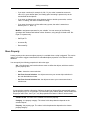
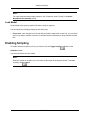
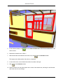
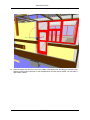
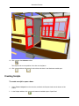
Opening a Gatehouse Door .......................................................................................... 430
Animating a Door .................................................................................................430
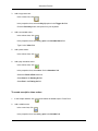
Creating Scripts ...................................................................................................433
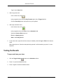
Testing the Results ..............................................................................................435
Part 6. Using TimeLiner ................................................................................................................ 436
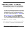
Chapter 41. Overview of TimeLiner ....................................................................................... 437
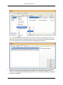
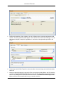
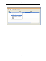
Working with the TimeLiner Window ............................................................................. 437
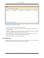
The Tasks Tab ....................................................................................................438
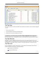
The Links Tab .....................................................................................................442
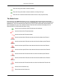
The Configure Tab ...............................................................................................444
The Rules Tab .....................................................................................................446
The Simulate Tab ................................................................................................446
The Select Link Dialog ......................................................................................... 448
Field Selector Dialog ............................................................................................448
The Simulation Settings Dialog ............................................................................. 450
The Overlay Text Dialog ....................................................................................... 456
Getting Started ............................................................................................................458
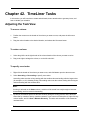
Chapter 42. TimeLiner Tasks ................................................................................................ 463
Adjusting the Task View ............................................................................................... 463
User Columns .............................................................................................................464
Creating Tasks ............................................................................................................464
Adding Tasks Manually ........................................................................................465
Adding Tasks Automatically ..................................................................................465
Editing Tasks ...............................................................................................................466
Deleting Tasks .............................................................................................................468
Attaching Tasks to Geometry ........................................................................................ 468
Attaching Tasks Manually .....................................................................................469
Using Rules to Attach Tasks ................................................................................. 470
Validating Project Schedule ..........................................................................................472
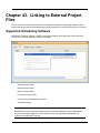
Chapter 43. Linking to External Project Files .......................................................................... 474
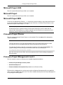
Supported Scheduling Software ....................................................................................474
Microsoft Project 2000 .........................................................................................475
Microsoft Project ..................................................................................................475
Microsoft Project MPX ..........................................................................................475
Primavera Project Planner ....................................................................................475
xi
Autodesk NavisWorks Manage 2009
Primavera Project Management 4 and 5 ................................................................ 475
Asta Power Project ..............................................................................................476
Adding and Managing Links ......................................................................................... 476
Adding Links .......................................................................................................476
Editing Links ........................................................................................................477
Deleting Links ......................................................................................................477
Building Tasks from Links ............................................................................................. 478
Synchronizing Tasks with Project Changes ................................................................... 478
Chapter 44. 4D Simulation ................................................................................................... 480
Playing Simulations .....................................................................................................480
Configuring Simulations ...............................................................................................480
Simulation Playback .............................................................................................480
Simulation Appearance ........................................................................................481
Chapter 45. Export ...............................................................................................................483
Chapter 46. TimeLiner Options ............................................................................................. 484
Chapter 47. Adding Animation .............................................................................................. 485
Overview .....................................................................................................................485
Adding Animation to an Entire Schedule ........................................................................ 485
Adding Animation to Tasks ........................................................................................... 489
Adding Scripts to Tasks ................................................................................................ 490
Part 7. Using Clash Detective ....................................................................................................... 491
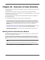
Chapter 48. Overview of Clash Detective .............................................................................. 492
Working with the Clash Detective Window ..................................................................... 492
The Batch Tab .....................................................................................................493
The Rules Tab .....................................................................................................494
The Select Tab ....................................................................................................495
The Results Tab ..................................................................................................497
The Report Tab ...................................................................................................500
Getting Started ............................................................................................................502
Chapter 49. Clash Batches ................................................................................................... 503
Running Clash Tests ....................................................................................................503
Managing batches of clash tests ................................................................................... 503
Merging clash tests from multiple files ........................................................................... 503
Importing clash tests ....................................................................................................503
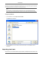
Exporting clash tests ....................................................................................................504
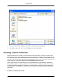
Creating custom clash tests .......................................................................................... 506
Chapter 50. Clash Rules ...................................................................................................... 508
Using Default Clash Rules ............................................................................................ 508
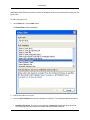
Adding Custom Clash Rules ......................................................................................... 508
Managing Clash Rules .................................................................................................511
Chapter 51. Selecting Items for Testing ................................................................................. 513
Selecting Items for a Clash Test ................................................................................... 513
Selecting Clash Test Options ........................................................................................ 513
Time-Based and Soft Clash Testing .............................................................................. 514
Time-Based Clashing ...........................................................................................514
Soft Clashing .......................................................................................................516
Time-Based Soft Clashing ....................................................................................517
Running a Clash Test ................................................................................................... 518
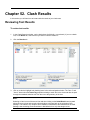
Chapter 52. Clash Results .................................................................................................... 519
Reviewing Test Results ................................................................................................519
Time-Based and Soft Clash Testing Results .................................................................. 521
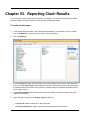
Chapter 53. Reporting Clash Results .................................................................................... 525
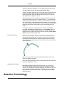
Glossary .....................................................................................................................................528
Index ..........................................................................................................................................535
xii
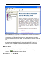
Part 1. Welcome to Autodesk
NavisWorks Manage 2009
Autodesk NavisWorks Manage 2009 software provides 3D construction project professionals with the
control and peace of mind of advanced interference management, analysis and coordination. 3D design
data created in building information modeling (BIM) applications such as the Revit family of products can
be combined with other design models and comprehensively reviewed, regardless of file size or format.
In this documentation you can find information on:
•
Installation
•
Basic NavisWorks Functionality
•
Presenter
•
Object Animation
•
TimeLiner
•
Clash Detective
Chapter 1. Autodesk NavisWorks Manage
2009 Readme
This section contains late-breaking information about Autodesk NavisWorks Manage 2009. For new and
updated information about all Autodesk© products, visit our website at http://www.autodesk.com.
Installing Autodesk NavisWorks Manage 2009
Release Version with Beta
If you have previously installed any beta version (including RC versions) of Autodesk NavisWorks
Manage 2009, you must completely uninstall these pre-release versions before installing the retail
version. Instructions to do this are posted on the beta portal in the Beta Readme files.
Exporters for 64 bit CAD systems
Autodesk NavisWorks Manage 2009 includes exporters for 64 bit versions of 3D Studio Max (9, 2008,
2009) and AutoCAD based products (2008, 2009). These exporters are packaged as a separate product
within the installer called "Autodesk NavisWorks 2009 (64 bit exporters)". This product will only be
available for installation on a 64 bit operating system and will be installed by default.
The 64 bit exporters require Autodesk NavisWorks Manage 2009 to be installed for full functionality.
Autodesk NavisWorks Manage 2009 should not be uninstalled without also uninstalling "Autodesk
NavisWorks 2009 (64 bit exporters)".
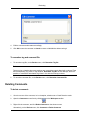
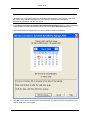
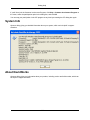
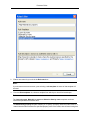
Customer Involvement Program
During the first week of Autodesk NavisWorks Manage 2009 use, a new window will appear to invite you
to join the Customer Involvement Program (CIP). By joining, NavisWorks will send anonymous data to
Autodesk related to the use of the application.
We strongly encourage you to participate in the program, and assure you there is no risk to your privacy.
We hope you will help us improve our product through this effort.
What does CIP track?
•
Number of minutes you are running the software.
•
Number of sessions that end due to stability issues.
•
Menu actions triggered.
•
Import/export actions (including file extension used).
•
Scene statistics after a load or import (number of objects, faces, vertices etc.).
•
Machine configuration (resolution, hard disks).
•
Other Autodesk products installed.
•
Plug-in (DLLS) installed with NavisWorks.
2
Autodesk NavisWorks Manage 2009
Readme
What does CIP not track?
•
There is no way for CIP to track any information related to the user.
•
There is also no way to track information outside of Autodesk products.
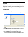
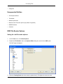
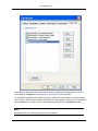
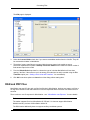
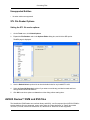
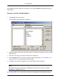
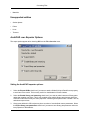
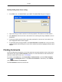
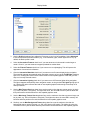
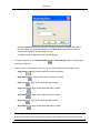
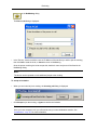
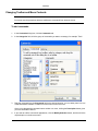
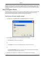
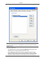
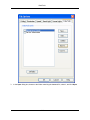
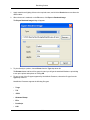
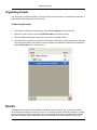
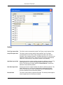
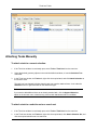
To turn CIP on and off:
•
Turn CIP on or off by going to Help > Customer Involvement Program.
The dialog will appear, allowing you to switch it on or off.
Product Notes
Supported file formats and applications
•
For an up to date list of supported file formats and applications go to NavisWorks Product Center.
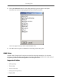
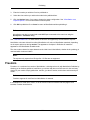
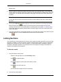
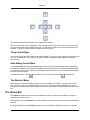
Autodesk Freedom
•
A free 3D viewer for NavisWorks NWD and Autodesk DWF files, Freedom is the answer for those
without design software or specialist skills that want to explore a project model.
•
Freedom offers an unrestricted, easy to use interface for real-time navigation of even the largest 3D
models complete with textures and materials, as well as animation playback, hyperlinks and saved
viewpoints.
•
Click here to install Freedom.
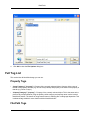
Resources
•
NavisWorks is provided with a number of sample models, which are installed in the Examples
directory within the Autodesk NavisWorks Manage 2009 installation directory
•
NavisWorks has a powerful API (Application Programming Interface) that allows developers to
customize the product. The API documentation and example files are installed in the API directory
within the Autodesk NavisWorks Manage 2009 installation directory
•
NavisWorks has support for ArchVision's RPCs for use with Presenter, and is provided with a number
of sample RPC files. The sample RPCs are installed in the
Presenter\lads\layla_data\textures\RPC directory within the Autodesk NavisWorks
Manage 2009 installation directory.
•
NavisWorks has support for Image Based Lighting through the use of High Dynamic Range Images
(HDRIs). The LightWorks User site has a number of resources for users of HDR Images:
3
Autodesk NavisWorks Manage 2009
Readme
Access the LightWork Design HDRI Resource Page
Access the LightWork Design HDRI Starter Collection
•
Microsoft .NET Framework
Earlier versions of Revit (Building 8 / Structures 2) require the .NET Framework version 1.1 to be
separately installed. If the .Net Framework version 1.1 is not installed an error message will be
displayed when Revit is started. You can download a copy of the .Net Framework version 1.1 by
searching for ".Net Framework version 1.1 redistributable package" in the downloads section of
Microsoft's website.
•
Adobe Reader
This is free software that enables the viewing and printing of Adobe's Portable Document Format
(PDF) files.
NavisWorks documentation is stored in PDF format, therefore, requiring this viewer to read them.
Download Adobe Reader
Known Problems in Autodesk NavisWorks Manage 2009
For an up-to-date list of outstanding issues in Autodesk NavisWorks Manage 2009, visit the NavisWorks
website at www.autodesk.com/navisworks.
Credits
Autodesk kindly acknowledges the following contributors to the NavisWorks example models:
•
National Ice Centre model courtesy of Design and Property services, Nottingham City Council,
Nottingham, England.
•
Scorpion TKX890 Snowmobile model courtesy of Scorpion Recreational Products, L.L.C. Manistee,
Michigan, USA
•
City of Bath model courtesy of the Centre for Advanced Studies in Architecture, University of Bath,
England.
•
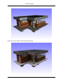
Gatehouse model courtesy of Dr. David Kerr, Taylor Woodrow, Taywood House, 345 Ruislip Road,
Southall UB1 2QX, England.
•
Eircom Park model courtesy of HBG Construction Ltd., Merit House, Colindale, London NW9 5AF,
England. Architects: RHWL Partnership, 77 Endell St. London WC2H 9DZ, England. Client: IMG
Ireland, 5 Clare St. Dublin 2 Ireland.
•
KLM model courtesy of Laing Ltd, Maxted House, 13 Maxted Road, Hemel Hempstead HP2 7DX,
England.
4
Chapter 2. New Features
Autodesk NavisWorks Manage 2009 contains many new features and enhancements.
Interface Enhancements
•
Object Animation
Animate objects across an animation timeline using simple but powerful object manipulation and
animation tools.
Interact with objects whilst they interact with the viewer, all via new simple but powerful scripting tools.
Link object movement with TimeLiner for precise object movement scheduling based on project tasks,
for more informative and realistic 4D process planning.
Link object movement with Presenter for enhanced worksite realism in exported photo-realistic
animations.
Link object movement with Clash Detective to automatically check for interferences between static and
moving objects, for example a door colliding with an obstructing column.
Link object movement with both TimeLiner and Clash Detective together for full time-based
interference checking. Scheduling the moving of a crane on-site could coincide with the delivery of
construction materials, all simulated in Autodesk NavisWorks Manage 2009, all checked for
scheduling and interference issues, all adding up to a powerful, automated workspace simulation and
planning tool.
•
.NET GUI Modernization
Up-to-date look and feel including new icons, improved control bar docking and tabbed control bars.
•
Workspaces
Allow predefined default window and menu layouts, as well as full customization and sharing of
layouts across multiple PCs.
•
New editor for Global Options.
A change from complex tabs to a logical tree structure, making finding options much simpler. Also
making global options sharable across multiple PCs through import and export.
Licensing Enhancements
•
FlexLM Licensing
The capability of check-in / check-out of licenses, timed-out licenses to automatically return
checked-out licenses after a set period of time.
•
Autodesk Standalone Licensing
Support for the well-known and well-documented Autodesk standard licensing technology.
5
New Features
Operating System Support
•
Microsoft Vista Support
Full support for Microsof's latest operating system.
•
64-bit Support
Support for 64-bit versions of both XP and Vista.
File Formats
•
3D Text Support
Visualization of 3D text from AutoCAD and MicroStation.
•
Parametric Support
Increasing cylinder accuracy, and dramatically reducing the memory footprint of file formats containing
them. Of key benefit to the MicroStation exporter and DGN file reader.
•
Object Animation Playback
Playback of object animations inside NWD and NWC files that have been created in Autodesk
NavisWorks Manage 2009 or Autodesk NavisWorks Simulate 2009.
•
File Format Updates
AutoCAD 2009 (32-bit and 64-bit)
Revit 2009
MAX 2008 and 2009
MAX 9 (32-bit and 64-bit)
VIZ 2008 and 2009
Inventor 2009
ArchiCAD 11
Faro 4.1
MicroGDS 10
Primavera v6
6
Part 2. Installation
This section provides step-by-step installation instructions for Autodesk NavisWorks Manage 2009. In
particular, you will learn how to:
•
Install stand-alone versions of the program
•
Install network-licensed or multi-seat stand-alone versions of the program
•
Upgrade the program
•
Troubleshoot your installation
Chapter 3. Quick Start to Stand-Alone
Installation
This section provides step-by-step instructions about how to install Autodesk NavisWorks Manage 2009
on your system. You should read the entire Standalone Installation Guide if you have any questions that
are not addressed in this Quick Start section.
For information about installing network-licensed or multi-seat stand-alone versions of the program, see
the Network Installation Guide.
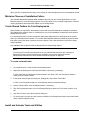
How to Prepare for Installation
Before you install Autodesk NavisWorks Manage 2009, you must review the system requirements,
understand administrative permission requirements, locate your Autodesk NavisWorks Manage 2009
serial number, and close all running applications. After you complete these tasks, you can install
Autodesk NavisWorks Manage 2009.
How to Review System Requirements
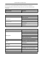
Make sure that the computer on which you install Autodesk NavisWorks Manage 2009 meets the system
requirements. If your system does not meet the system requirements, many problems can occur, both
within Autodesk NavisWorks Manage 2009 and at the operating system level.
To review the system requirements, see “ System Requirements ”.
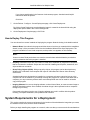
How to Understand Administrative Permission Requirements
To install Autodesk NavisWorks Manage 2009, you must have administrator permissions. You do not
need to have domain administrative permissions. See your system administrator for information about
administrative permissions.
To run Autodesk NavisWorks Manage 2009, you do not need administrator permissions. You can run the
program as a limited user.
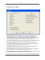
How to Install Multiple or Bundled Products
Some Autodesk packages are comprised of multiple products or are part of multi-product bundles. The
Installation wizard for packages that are comprised of multiple products gives you the option to choose
which products you want to install. During the install process, you’ll be informed whether a copy of the
software is already installed or you’ll be warned if your system does not meet the minimum system
requirements for the product. Each product is displayed on its own tabbed panel and you can individually
configure them to specifically fit your needs.
If you’ve purchased a package that is a multi-product bundle, such as am educational or institutional
packages, you may have a package that includes several Autodesk products. For these bundled
packages, an Installer Disk contains information for all the products in the package. The Installer Disk
helps manage all of the products being installed.
How to Locate Your Autodesk NavisWorks Manage 2009 Serial
Number
8
Quick Start to Stand-Alone Installation
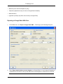
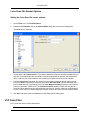
When you are activating Autodesk NavisWorks Manage 2009, you are prompted for your serial number.
Your serial number is located on the outside of the product package. Make sure to have this number
available before you activate the program so that you don't have to stop in the middle of the installation.
How to Avoid Data Loss During Installation
The Autodesk NavisWorks Manage 2009 installation process may stop if some applications (such as
Microsoft® Outlook® or virus-checking programs) are running. Close all running applications to avoid
possible data loss.
How to Install and Run Autodesk NavisWorks Manage
2009
To use the product, you must install the product, register and activate it, and then launch it.
How to Install Autodesk NavisWorks Manage 2009
Autodesk NavisWorks Manage 2009 ships on single DVD. The installation process has been streamlined
by means of the Installation wizard.
1.
Insert the NavisWorks DVD into your computer's media drive.
The Installation wizard launches in the language that best matches the settings on your computer.
If the Installation wizard does not start automatically, double-click Setup.exe at the root of the
NavisWorks DVD.
2.
In the NavisWorks Installation wizard, click Install Products.
3.
Follow the directions on each installation page.
Note:
When you select Install without making any changes, the Installation wizard asks you to confirm
you want to continue installing using the default configuration. If you select Yes, a Typical
installation takes place.
For more information about installing NavisWorks, see “ Install NavisWorks ”.
How to Register and Activate NavisWorks
After NavisWorks is installed, you can initiate the registration process by launching the product. When you
launch NavisWorks, the Product Activation wizard is displayed. Follow the directions in the Product
Activation wizard to register the product.
Make sure you have your product serial number available. You cannot register and activate NavisWorks
without it.
Note:
9
Quick Start to Stand-Alone Installation
If you are upgrading from an earlier release of NavisWorks, use your new serial number when
you register and activate the new release.
For more information about registering NavisWorks, see “ Register and Activate NavisWorks ”.
How to Launch NavisWorks
Assuming that you've followed all of the previous steps outlined in this Quick Start section, you can
launch NavisWorks and start taking advantage of its new and updated features.
You can start NavisWorks in the following ways:
•
Desktop shortcut icon. When you install NavisWorks, a NavisWorks shortcut icon is placed on your
desktop. Double-click the NavisWorks icon to start NavisWorks.
•
Start menu. On the Start menu, click Programs (Windows XP) or All Programs (Windows Vista)
Autodesk > Autodesk NavisWorks Manage 2009 > Autodesk NavisWorks Manage 2009.
•
Location where NavisWorks is installed. If you have administrative permissions, you can run
NavisWorks in the location where you installed it. If you are a limited-rights user, you must run
NavisWorks from the Start menu or from the desktop shortcut icon. If you want to create a custom
shortcut, make sure that the Start In directory for the shortcut points to a directory where you have
write permissions.
How to Launch NavisWorks in Another Language
To run NavisWorks in another of the supported languages, you need to add one of the language selector
arguments to the desktop shortcut.
1.
Right-click the NavisWorks desktop shortcut, and click Properties on the shortcut menu to open the
NavisWorks Properties dialog box.
2.
On the Shortcut tab, enter a space in the Target field after ..\roamer.exe", and then enter one of the
following arguments:
3.
-lang enu
Enter this for English localization
-lang deu
Enter this for German localization
-lang jpn
Enter this for Japanese localization
-lang rus
Enter this for Russian localization
-lang chs
Enter this for Chinese (PRC) localization
Click OK to save the changes.
10
Chapter 4. Move to NavisWorks from a
Previous Release
If you have a previous version of NavisWorks installed on your system, you can install Autodesk
NavisWorks Manage 2009 and keep other versions of the program on the same system. This is called a
side-by-side installation.
If you've purchased a version of Autodesk NavisWorks Manage 2009, which is labeled as an upgrade,
you are required to uninstall the previous version within 120 days of installing Autodesk NavisWorks
Manage 2009. See your license agreement for more information.
11
Chapter 5. Install NavisWorks for an
Individual User
This section provides instructions for installing and activating your Autodesk products for an individual
user on a stand-alone computer. For information about installing network-licensed or multi-seat
stand-alone versions of the program, see the Network Installation Guide.
The NavisWorks Installation Wizard
The Autodesk NavisWorks Manage 2009 Installation Wizard contains all installation-related material in
one place. From the Installation wizard, you can access user documentation, install the product and
supplemental tools, view support solutions, and learn about deploying your product on a network.
Note:
Autodesk NavisWorks Manage 2009 ships on a single DVD. Insert the Autodesk NavisWorks
Manage 2009 DVD in your DVD drive to start the installation process. Follow the prompts to
complete the installation. As long as the DVD is in the drive, you can access documentation by
clicking the documentation link.
•
Review installation documentation before you install. Click the Read the Documentation link to
launch the Help system, and read the Welcome to Autodesk NavisWorks Manage 2009 and
Installation sections.
•
Install Autodesk NavisWorks Manage 2009. From the Installation wizard, click Install Products.
Follow the on-screen instructions to complete the installation.
System Requirements
Before you install your product on a stand-alone computer, make sure that your computer meets the
minimum system requirements. See the following table for hardware and software requirements.
Hardware and software requirements
Hardware/Software
Requirement
Windows©XP© Professional, SP 2 (recommended)
Windows XP Home, and Professional, SP 2
Windows Vista Ultimate
Windows Vista Enterprise
Operating system
Windows Vista Business
Windows Vista Home Premium
Windows Vista Home Basic
Web browser
Microsoft© Internet Explorer 6.0, SP 1 (or later)
AMD©Athlon©, 3.0 GHz or faster (minimum)
Intel©Pentium© IV, 3.0 GHz or faster
(recommended)
Processor
12
Install NavisWorks for an Individual User
Hardware and software requirements
512 MB (minimum)
Memory (RAM)
2 GB or greater (recommended)
128 meg, 1024 x 768 VGA, True Color (minimum)
Display card
256 meg or greater - 1280 x 1024 32-bit color video
display adapter, True Color (recommended)
Hard disk
Installation 800 MB
Pointing device
MS-Mouse compliant
DVD-ROM
Any speed (for installation only)
Open GL©-compatible 3D video card
Printer or plotter
Optional hardware
Modem or access to an Internet connection
Network interface card
Install NavisWorks
This section contains information for installing Autodesk NavisWorks Manage 2009 on a stand-alone
computer. You must have administrative permissions to install NavisWorks.
Your DVD is required to install NavisWorks. Insert the Autodesk NavisWorks Manage 2009 DVD to start
the installation process. Follow the prompts to complete the installation.
To install NavisWorks using default values on a stand-alone
computer
This is the fastest means of installing NavisWorks on your system. Only default values are used which
means it is a typical installation being installed to C:\Program Files\Autodesk NavisWorks
Manage 2009.
1.
Insert the Autodesk NavisWorks Manage 2009 DVD into your computer's DVD drive.
The Autodesk NavisWorks Manage 2009 Installation wizard launches in the language that best
matches the settings on your computer.
If the Installation wizard does not start automatically, double-click Setup.exe at the root of the
NavisWorks DVD.
2.
In the Installation wizard, click Install Products.
3.
Select the product you want to install and click Next.
4.
Review the Autodesk software license agreement for your country or region. You must accept this
agreement to proceed with the installation. Choose your country or region, click I Accept, and then
click Next.
Note:
If you do not agree to the terms of the license and want to terminate the installation, click Cancel.
13
Install NavisWorks for an Individual User
5.
On the Personalize the Products page, enter your serial number and user information and click Next.
The information you enter here is permanent and is displayed in the Autodesk NavisWorks Manage
2009 window (accessed by Help > About) on your computer. Because you can't change this
information later without uninstalling the product, make sure you enter the correct information now.
6.
On the Review - Configure - Install page, click Install to begin installing. Then select Yes, to continue
installing using the default configuration.
The wizard does the following:
•
Uses a Typical installation, which installs the most common application features.
To see which features are included in a Typical installation, refer to “ When performing a Typical
installation, what gets installed? ”.
•
Installs NavisWorks to the default install path of C:\Program Files\Autodesk NavisWorks
Manage 2009 .
7.
On the Installation Complete page, select View the Autodesk NavisWorks Manage 2009 Readme if
you want to launch the Autodesk NavisWorks Manage 2009 Help system.
8.
Click Finish.
To install NavisWorks using using configured values on a
stand-alone computer
With this installation method, you can fine-tune exactly what gets installed by using the Configure option.
You can alter the installation type, the installation path and the license type.
1.
Insert the Autodesk NavisWorks Manage 2009 DVD into your computer's DVD drive.
The Autodesk NavisWorks Manage 2009 Installation wizard launches in the language that best
matches the settings on your computer.
If the Installation wizard does not start automatically, double-click Setup.exe at the root of the
NavisWorks DVD.
2.
In the Installation wizard, click Install Products.
3.
Select the product you want to install and click Next.
4.
Review the Autodesk software license agreement for your country or region. You must accept this
agreement to proceed with the installation. Choose your country or region, click I Accept, and then
click Next.
Note:
If you do not agree to the terms of the license and want to terminate the installation, click Cancel.
14
Install NavisWorks for an Individual User
5.
On the Personalize the Products page, enter your serial number and user information and click Next.
The information you enter here is permanent and is displayed in the Autodesk NavisWorks Manage
2009 window (accessed by Help > About) on your computer. Because you can't change this
information later without uninstalling the product, make sure you enter the correct information now.
6.
On the Review - Configure - Install page, click Configure to make configuration changes such as
changing the installation type, or changing the installation path.
7.
On the Select License Type page, select Stand-Alone License, and then click Next.
8.
On the Select the Installation Type page, you can choose to make the following configuration
changes:
•
Select Features To Install - use the check boxes to select only the features you want to install:
Autodesk NavisWorks Manage 2009 - contains full set of Autodesk NavisWorks Manage
2009 files.
API - contains the Component Object Model interface for customising and extending the
NavisWorks functionality.
Sample RPC's - contains several Rich Photorealistic Content files for the Presenter tool.
Example NWD files - contains various feature sample files.
PDF manual - contains the Autodesk NavisWorks Manage 2009 user guide in PDF
format.
Note:
To view or print any files with an extension of .pdf, Adobe® Reader must be installed on your
computer. If you do not have Adobe Reader, you can download the latest version by visiting
http://www.adobe.com.
Exporter Plugins - contains various exporter plugins. These plugins enable models to be
exported into native Autodesk NavisWorks Manage 2009 file format from within the
corresponding 3rd party software. By default, the Installation wizard will enable the
exporter plugins for all 3rd party products installed on your PC.
Note:
For some plugins, you must have the 3rd party software installed on your PC to be able to select
them.
•
Product Install Path - use the browse button to select the drive and location where Autodesk
NavisWorks Manage 2009 will be installed.
If you are enabling exporter plugins for the 3rd party software, which is not installed on your PC,
you must use this field to browse to the correct location in the software installation directory.
Click Next to proceed with the configuration process.
15
Install NavisWorks for an Individual User
9.
On the Configuration Complete page, click Configuration Complete to return to the Review Configure - Install page. Then, click Install.
10. On the Installation Complete page, select View the Autodesk NavisWorks Manage 2009 Readme if
you want to launch the Autodesk NavisWorks Manage 2009 Help system.
11. Click Finish.
You have successfully installed Autodesk NavisWorks Manage 2009. You are now ready to register your
product and start using the program. To register the product, start Autodesk NavisWorks Manage 2009
and follow the on-screen instructions.
Note:
Autodesk does not recommend or support the distribution of an Autodesk product using imaging
software. However, if you plan to use this method of distribution, please review the instructions
detailed in Distribute the Product Using Imaging Software in the Network Installation Guide.
Register and Activate NavisWorks
The first time you start Autodesk NavisWorks Manage 2009, the Product Activation wizard is displayed.
You can either activate NavisWorks at that time or run NavisWorks and activate it later. Until you register
and enter a valid activation code for Autodesk NavisWorks Manage 2009, you are operating the program
in trial mode and the Product Activation wizard is displayed for 30 days from the first time that you run the
program. If after 30 days of running Autodesk NavisWorks Manage 2009 in trial mode you have not
registered and provided a valid activation code, your only option is to register and activate Autodesk
NavisWorks Manage 2009. You will not be able to run in trial mode after the 30 days expires. Once you
register and activate Autodesk NavisWorks Manage 2009, the Product Activation wizard is no longer
displayed.
The fastest and most reliable way to register and activate your product is by using the Internet. Simply
enter your registration information and send it to Autodesk over the Internet. Once you submit your
information, registration and activation occur almost instantly.
To register and activate Autodesk NavisWorks Manage 2009:
1.
Click Start menu > Programs (Windows XP) or All Programs (Windows Vista) > Autodesk > Autodesk
NavisWorks Manage 2009 > Autodesk NavisWorks Manage 2009.
2.
In the Autodesk NavisWorks Manage 2009 Product Activation wizard, select Activate the Product,
and then click Next.
This starts the Register Today process.
3.
Click Get an Activation Code.
4.
Click Next and follow the on-screen instructions.
If you do not have Internet access, or if you want to use another method of registration, you can register
16
Install NavisWorks for an Individual User
and activate Autodesk NavisWorks Manage 2009 in one of the following ways:
•
Email. Create an email message with your registration information and send it to Autodesk.
•
Fax or Post/Mail. Enter your registration information, and fax or mail the information to Autodesk.
Add or Remove Features
You can add or remove Autodesk NavisWorks Manage 2009 features at any time. For example, you may
have chosen a Custom installation option when you first installed NavisWorks, but now you want to add
features that you did not install originally. Or you may no longer need to use all of the features that were
installed originally. You can add or remove features by using the Add or Remove Programs dialog box.
To add or remove features:
1.
In the Control Panel, double-click Add or Remove Programs.
2.
In the Add or Remove Programs dialog box, click Autodesk NavisWorks Manage 2009, and then click
Change/Remove in Windows XP or Uninstall/Change in Vista.
The Autodesk NavisWorks Manage 2009 Installation wizard re-opens in Maintenance Mode.
3.
Click Add or Remove Features.
4.
On the Add/Remove Features page, select a feature to install or uninstall. The icons to the left of the
selections give you an indication of the action that will be taken.
- indicates a feature that was originally not installed.
- indicates a currently installed feature or a feature that you want to add.
- indicates an originally installed feature that is chosen for removal.
Note:
If you need to revert to the Autodesk NavisWorks Manage 2009 features that you selected in your
original installation, click Cancel.
Click Next.
5.
On the Update Autodesk NavisWorks Manage 2009 Installation page, click Next.
6.
On the Update Complete page, you are informed when the updates have been performed. Click
Finish.
Reinstall or Repair Autodesk NavisWorks Manage 2009
If you accidentally delete or alter files that are required by Autodesk NavisWorks Manage 2009,
17
Install NavisWorks for an Individual User
NavisWorks might not perform correctly, and you might receive error messages when you try to execute a
command or find a file. You can attempt to fix this problem by reinstalling or repairing Autodesk
NavisWorks Manage 2009. The reinstallation or repair uses the features that were part of the installation
type you chose when you initially installed the program.
To reinstall or repair Autodesk NavisWorks Manage 2009:
1.
In the Control Panel, double-click Add or Remove Programs.
2.
In the Add or Remove Programs dialog box, click Autodesk NavisWorks Manage 2009, and then click
Change/Remove in Windows XP or Uninstall/Change in Vista.
The Autodesk NavisWorks Manage 2009 Installation wizard re-opens in Maintenance Mode.
3.
Click Repair Autodesk NavisWorks Manage 2009.
4.
On the Select Repair or Reinstall page, click one of the following, and then click Next:
•
Repair My Autodesk NavisWorks Manage 2009 Installation. This option replaces all registry
entries that NavisWorks initially installed and restores Autodesk NavisWorks Manage 2009 to its
default state.
•
Reinstall My Autodesk NavisWorks Manage 2009 Installation. This option repairs the registry
and reinstalls all files from the original installation. Use this option if the Repair My Autodesk
NavisWorks Manage 2009 Installation option does not solve the problem.
5.
On the Repair Autodesk NavisWorks Manage 2009 page, click Next to start the process.
6.
On the Repair Complete page, you are informed when the repairs have been performed. Click Finish.
Uninstall Autodesk NavisWorks Manage 2009
When you uninstall Autodesk NavisWorks Manage 2009, all components are removed. This means that
even if you've previously added or removed components, or if you've reinstalled or repaired Autodesk
NavisWorks Manage 2009, the uninstall removes all NavisWorks installation files from your system.
To uninstall Autodesk NavisWorks Manage 2009:
1.
In the Control Panel, double-click Add or Remove Programs.
2.
In the Add or Remove Programs dialog box, click Autodesk NavisWorks Manage 2009, and then click
Change/Remove in Windows XP or Uninstall/Change in Vista.
The Autodesk NavisWorks Manage 2009 Installation wizard re-opens in Maintenance Mode.
3.
Click Uninstall.
4.
On the Uninstall Autodesk NavisWorks Manage 2009 page, click Next to remove NavisWorks from
the system.
18
Install NavisWorks for an Individual User
5.
When informed that the product has been successfully uninstalled, click Finish.
Note:
Even though Autodesk NavisWorks Manage 2009 is removed from your system, the software
license remains. If you reinstall Autodesk NavisWorks Manage 2009 at some future time, you will
not have to register and re-activate the program.
19
Chapter 6. Install NavisWorks for Multiple
Users
This section provides step-by-step instructions for installing network-licensed or multi-seat stand-alone
versions of the Autodesk NavisWorks Manage 2009.
Quick Start to Network Installation
Network deployment of this program requires careful planning and execution. If you are not familiar with
network administration and deployment, you should read the entire Network Installation Guide before you
attempt to deploy and administer the program over a network.
How to Prepare for Deployment
To prepare for a deployment, you need to choose an installation type and a license server model.
How to Choose an Installation Type
When you set up your deployment, you need to choose the type of installation to deploy. In the Autodesk
NavisWorks Manage 2009 Installation wizard, you specify one of the following installation types:
•
Network License installation. With this type of installation, you install the program to workstations
with the files and registry entries that allow the program to communicate with the Network License
Manager. You also define the configuration of the Network License Manager so that the licenses can
be accessed. Workstations running the program based on a network installation do not require
individual activation. Licensing of this program is managed by at least one license server.
The main advantage is that you can install Autodesk NavisWorks Manage 2009 on more systems than
the number of licenses you have purchased (for example, purchasing 25 licenses but installing on 40
workstations). At any one time, Autodesk NavisWorks Manage 2009 runs on the maximum number of
systems for which you have licenses. This means you get a true floating license.
•
Multi-Seat Stand-Alone installation (Stand-Alone option). Choose this type of installation for
stand-alone installations where a single serial number is used for multiple seats. Multi-seat
stand-alone installations do not rely upon a Network License Manager to manage product licenses;
however, you can still use the Autodesk NavisWorks Manage 2009 Installation wizard to create
administrative images and create deployments. Registration and activation is more automated for
multi-seat stand-alone installations. After the first activation using the multi-seat stand-alone serial
number, activation occurs automatically for all workstations based on this deployment, as long as your
systems are connected to the Internet.
•
Stand-Alone installation (Stand-Alone option). Choose this type of installation for stand-alone
installations where a single serial number is used for a single seat. Like a multi-seat stand-alone
installation, you do not use the Network License Manager to manage product licensing, but
installation, registration, and activation occurs on each workstation.
If you choose one of the Stand-Alone installation types, you can proceed to “How to Set Up and Distribute
the Program”.
How to Choose a License Server Model
20
Install NavisWorks for Multiple Users
If you chose the Network Installation option, you need to decide which license server model to use to
distribute the product licenses.
Note:
If you are deploying a stand-alone or multi-seat stand-alone installation type, you do not use a
license server model. Proceed to “How to Set Up and Distribute the Program”.
For the network installation, use one of the following license server models:
•
Single license server model. The Network License Manager is installed on a single server, so
license management and activity is restricted to this server. A single license file represents the total
number of licenses available on the server.
•
Distributed license server model. Licenses are distributed across more than one server. A unique
license file is required for each server. To create a distributed license server, you must run the
Network License Manager on each server that is part of the distributed server pool.
•
Redundant license server model. You use three servers to authenticate a single license file. One
server acts as the master, while the other two provide backup if the master server fails. With this
configuration, licenses continue to be monitored and issued as long as at least two servers are still
functional. The license file on all three servers is the same. You must install the Network License
Manager on each server.
Each of these license server models is described in detail in the Network Licensing Guide. It is strongly
recommended that you read that guide before you deploy the program. You can find the Network
Licensing Guide by clicking the Documentation link at the lower left corner of the Autodesk NavisWorks
Manage 2009 Installation wizard
How to Set Up a License Server
If you are planning to have users run the program using network licenses, you need to use the Network
License Manager and the Network License Activation utility.
The Network License Manager helps you configure and manage license servers. The Network License
Activation utility helps you get licenses and register them over the Internet.
How to Install the Network License Manager
The Network License Manager is used to configure and manage the license servers.
To install your Network License Manager:
1.
In the Autodesk NavisWorks Manage 2009 Installation wizard, click Install Tools and Utilities.
2.
On the Select the Products to Install page, select Autodesk Network License Manager and click Next.
3.
Review the Autodesk software license agreement for your country or region. You must accept this
agreement to proceed with the installation. Choose your country or region, click I Accept, and then
click Next.
Note:
21
Install NavisWorks for Multiple Users
If you do not agree to the terms of the license and want to terminate the installation, click Cancel.
4.
On the Review - Configure - Install page, review your product selection and the current settings. If
you don't want to make any changes, click Install. If you want to change the install type or installation
path, click Configure.
5.
On the Select the Installation Type page, accept the default installation path (C:\Program
Files\Autodesk Network License Manager\) or Browse to specify a different path. If you
enter a path that does not exist, a new folder is created using the name and location you provide.
Click Next.
Note:
Do not install the Network License Manager on a remote drive. When you install the Network
License Manager files, you must provide a path to a local drive. You must specify the drive letter;
the universal naming convention (UNC) is not supported.
6.
On the Configuration Complete page, click Configuration Complete to return to the confirmation
page.
7.
On the Review - Configure - Install page, click Install.
8.
When the Installation Complete page displays, click Finish.
How to Install and Use the Network License Activation Utility
With the Network License Activation utility, you can obtain licenses over the Internet, which saves time
and effort in setting up a network-licensed version of the program. In addition, you can register your
product, get automated support by email if you cannot obtain a license over the Internet, and save and
migrate license files automatically.
To install your Network License Activation utility:
1.
In the Autodesk NavisWorks Manage 2009 Installation wizard, click Install Tools and Utilities.
2.
On the Select the Products to Install page, select Autodesk Network License Activation Utility and
click Next.
3.
Review the Autodesk software license agreement for your country or region. You must accept this
agreement to proceed with the installation. Choose your country or region, click I Accept, and then
click Next.
Note:
If you do not agree to the terms of the license and want to terminate the installation, click Cancel.
4.
On the Review - Configure - Install page, review your product selection and the current settings. If
you don’t want to make any changes, click Install. If you want to change the install type or installation
path, click Configure.
22
Install NavisWorks for Multiple Users
5.
On the Select the Installation Type page, either accept the default installation path (C:\Program
Files\Autodesk Network License Manager\Network License Activation
Utility\enu\) or Browse to specify a different path. If you enter a path that does not exist, a new
folder is created using the name and location you provide. Click Next.
6.
On the Configuration Complete page, click Configuration Complete to return to the confirmation
page.
7.
On the Review - Configure - Install page, click Install.
8.
When the Installation Complete page displays, click Finish.
To use your Network License Activation utility:
1.
Click Start menu > Programs (Windows XP) or All Programs (Windows Vista) > Autodesk > Network
License Manager > Autodesk NavisWorks Manage 2009 Network License Activation Utility.
2.
On the Obtain a Network License page, review how this utility works and the requirements for using
it, and then click Next.
3.
On the Server Information page, enter the product serial number.
Note:
If you are modifying an existing license file or obtaining a new license for an existing product, your
previously entered information might be displayed. Make sure that the serial number that is
displayed is the one you want to license. If it is not, enter the correct product serial number.
4.
In the License Server Model section, click a license server model. For more information about each
license server model, click the ? button.
5.
In the Server Host Name box, enter a server host name or click the [...] button to locate the name of
each server you plan to use.
6.
In the Host ID box, for each server host name you entered in the previous step, click Lookup to have
the utility automatically locate the host ID for the server, or enter the host ID manually.
Note:
If your server has more than one network adapter, select the one that corresponds to a physical
network adapter. To determine which adapters are physical, enter ipconfig /all at a Windows
command prompt and view the Description field above each physical address. If there is more
than one physical network adapter, you can use any one of them, as long as it was listed when
you ran ipconfig /all. Logical devices such as VPN adapters, PPP adapters, and modems may be
listed but are not usable for licensing.
7.
If you chose Distributed Server in the License Server Model section, the Seats box is displayed. In
the Seats box, enter the number of seats for each license server, and then click Next.
8.
On the Confirm Server Information page, review the server information you entered, and click Next.
9.
If the Register and License Your Autodesk Product page is displayed, do all of the following, and
23
Install NavisWorks for Multiple Users
then click Next.
In the This Product Is To Be Registered To option, select Company or Individual.
In the Select Country or Region section, select your country or region of residence.
In the Is This an Upgrade section, select Yes or No.
10. If the Registration Information page is displayed, enter your registration information, and then click
Next.
11. If the Confirm Information page is displayed, review your registration information, and then click Next.
12. If the Connecting page is displayed, click Next to connect to the Internet to obtain your network
license.
13. On the Licenses Received page, in the Save License File for [computer name] dialog box, enter the
location where you want to save your license file, or click Browse to navigate to the location.
14. If you have an existing license file from another Autodesk product, select one of the following options:
•
Insert the New License Information Into It. The new license information is added into the
existing license file.
•
Overwrite the Existing License File. The entire contents of the existing license file is replaced
with the new license information. Select this option only if you no longer require any part of the
existing license file contents.
15. Click Next.
16. On the License Activation Successful page, click Print to save a printed copy of the license
information, or click Done to complete the transaction and exit the Network Activation utility.
How to Configure Your License Server
You configure a license server so that you can manage the Autodesk product licenses you received when
you ran the Network License Activation utility. Configure the license server with the lmtools.exe utility.
You should be logged in with Administrator rights when working with the LMTOOLS utility.
To configure your license server:
1.
Do one of the following:
•
Click Start menu > Programs (Windows XP) or All Programs (Windows Vista) > Autodesk >
Network License Manager > LMTOOLS.
•
Right-click the LMTOOLS icon (Windows Vista) on the desktop and click Run As Administrator.
24
Install NavisWorks for Multiple Users
2.
In the Lmtools program, on the Service/License File tab, select the Configure Using Services option.
3.
Click the Config Services tab.
4.
On the Config Services tab, in the Service Name list, select a service name or do one of the
following:
•
If a service name is selected, verify that it is the one you want to use to manage licenses.
•
If no service name exists, enter the service name you want to use to manage licenses.
Note:
If you have more than one software vendor using FLEXlm® for license management, the Service
Name list contains more than one option.
5.
In the Path to Lmgrd.exe File box, enter the path to the Network License Manager daemon
(lmgrd.exe), or click Browse to locate the file.
By default, this daemon is installed in the \Program Files\Autodesk Network License
Manager folder.
6.
In the Path to the License File box, enter the path to your license file, or click Browse to locate the
file.
7.
In the Path to the Debug Log File box, enter a path to create a debug log, or click Browse to locate
an existing log file.
8.
To run lmgrd.exe as a service, select Use Services.
9.
To automatically start lmgrd.exe when the system starts, select Start Server at Power Up.
10. Click Save Service to save the new configuration under the service name you selected on the Config
Services tab. Then click Yes.
11. Click the Start/Stop/Reread tab.
12. On the Start/Stop/Reread tab, do one of the following:
•
If a service has not yet been defined for Autodesk, click Start Server to start the license server.
•
If a service for Autodesk is already defined and running, click ReRead to refresh the Network
License Manager with any changes made to the license file or Options file.
The license server starts running and is ready to respond to client requests.
13. Close lmtools.exe.
How to Set Up and Distribute the Program
Once you have prepared for deployment and you have used the Network License Manager and the
Network License Activation utility, you are ready to set up and distribute this program by using the
25
Install NavisWorks for Multiple Users
Autodesk NavisWorks Manage 2009 Installation wizard and choosing a deployment method.
How to Create a Network Share
A network share is an installation folder that you make available to users' computers on a network. You
point users to this location to install the program. Create a network share that will be used by the
Autodesk NavisWorks Manage 2009 Installation wizard during the creation of a client deployment.
You must have Full Control permissions set for your shared folder when you are creating your
deployment images. Read permissions are necessary to access the network share and administrative
permissions on the workstation where the program is deployed.
To create your network share:
1.
On the desktop of a network server, create a folder named Autodesk.
2.
Right-click the Autodesk folder and click Share and Security (or Sharing).
3.
In the [folder name] Properties dialog box, Sharing tab, select Share This Folder.
4.
Specify a Share Name, such as Autodesk or MyDeployments, if necessary.
5.
Click the Permissions button. In the Permissions dialog box make sure Full Control is active. Click
OK.
In Vista, right-click the Autodesk folder and then click Share. In the Properties dialog box select
Sharing and then Advanced Sharing to share the folder. Click the Permissions button to make sure
Full Control is active. Click OK.
These steps are important when creating your deployment images.
6.
Click OK or Close to close the Properties dialog box.
7.
For each product you plan to install, create a subfolder in the Autodesk folder. Name each folder with
the pertinent product name.
How to Use the Installation Wizard to Set Up a Deployment
You can create a deployment directly from the Autodesk NavisWorks Manage 2009 Installation wizard.
From the deployment, users can install the program on their computers.
Note:
The following procedure illustrates just one of the ways you can set up a deployment. This
procedure details a single-server network deployment with a Typical client setup type and no
customizations. For further information about setting up deployments, see Use the Installation
Wizard to Set Up a Deployment.
To use the Installation wizard to create a default deployment:
26
Install NavisWorks for Multiple Users
1.
In the Autodesk NavisWorks Manage 2009 Installation wizard, click Create Deployments.
2.
On the Begin Deployment page, you need to specify the following: administrative image location and
deployment name.
In the administrative image field, enter an existing shared network location where you
want to create an administrative image, or click the Browse button to navigate to a
location where there is a shared network location. Users install the program from this
location. If you do not know how to create a network share, see “How to Create a
Network Share”.
In the deployment name field, enter the new deployment's name. The name you enter
here is the name of the shortcut your users will access to install the product.
Click Next.
3.
On the Select the Products to Include in the Deployment page, choose the products you want to
deploy and click Next.
4.
Review the Autodesk software license agreement for your country or region. You must accept this
agreement to proceed with the installation. Choose your country or region, click I Accept, and then
click Next.
Note:
If you do not agree to the terms of the license and want to terminate the installation, click Cancel.
5.
On the Product and User Information page, enter your serial number and user information and click
Next.
Note:
The information you enter here is permanent and is displayed in the Autodesk NavisWorks
Manage 2009 window (accessed by Help > About) on your computer. Because you can't change
this information later without uninstalling the product, make sure you enter the correct information
now.
6.
On the General Deployment Settings page, choose if you want the deployment to create a network
log and/or a client log, run the client installation in silent mode, and if you want users to participate in
the Customer Involvement program.
When you choose to create a network log file, you also have to specify where the log file
is created by entering either a valid UNC (universal naming convention) path or
hard-coded path on your network. The network log file is optional.
Note:
The folder where the network log resides must be a shared folder where users who install the
program have Change permissions. Otherwise, successes or failures for user installations cannot
be written to the log file.
Choose whether you want a client log file created.
If you want to prevent users from changing installation settings when they install, select
Silent mode.
27
Install NavisWorks for Multiple Users
If you choose participation in the Customer Involvement program, Autodesk sends helpful
information about the product.
Click Next.
7.
On the Review - Configure - Create Deployment page, click Create Deployment.
By clicking Create Deployment, an administrative image is created in the shared folder using the
deployment options listed in the Current Settings field.
8.
On the Deployment Complete page, click Finish.
How to Deploy This Program
You can choose from several methods of deploying the program. Network sharing is the default method.
•
Network Share. Users launch the program with the shortcut icon that you created with the Installation
wizard, in step 3 of the procedure How to Use the Installation Wizard to Set Up a Deployment. The
program is installed on users' local computers, and a product icon appears on their desktop.
Note:
Users must have Read permissions to access the network share and administrative permissions
on the workstation where this program is installed.
•
Scripting. Installation scripts are most useful for stand-alone installation of programs on computers
that are connected to a network. Scripts are also useful for installing service packs, extensions, and
object enablers on a network.
•
Group Policy Objects (GPOs). With group policy objects, this program can be advertised to any
Windows XP or Windows Vista computer that is part of a Windows 2003 Server Active Directory
environment.
Autodesk products are designed to be installed on a computer so that any user who logs on to the
computer can run the software. If you attempt to assign this program for a specific user rather than a
computer, you may encounter problems when a second specified user tries to install or uninstall a
copy of the program.
•
Imaging Software.You can use imaging software, such as Norton Ghost, to create a master image to
distribute Autodesk products. Once created, the master image is then replicated to other computers
throughout your facility.
Care needs to be taken since the use of imaging software can result in conflicts with the product
licensing, incomplete installations, and problems with activation.
System Requirements for a Deployment
This section contains the system requirements for the location of the administrative image that you create,
the network license server, and the client workstation.
Before you begin installing the program on a network, make sure that your servers and client workstations
28
Install NavisWorks for Multiple Users
meet the minimum recommended hardware and software requirements for a deployment.
See the following tables for administrative image, license server, and client workstation system
requirements.
Hardware and software requirements for the location of the administrative image
Hardware/Software
Requirement
Hard disk
1.5 GB (recommended)
Hardware and software requirements for the the network license server
Hardware/Software
Requirement
Windows Vista 32-bit
Windows XP 32-bit
Operating system
Windows 2003 Server Edition
AMD©Athlon©, 3.0 GHz or faster (minimum)
Computer/processor
Intel©Pentium© IV, 3.0 GHz or faster
(recommended)
Network interface card
Compatible with existing Ethernet network
infrastructure
Communication protocol
TCP/IP
Hardware and software requirements for client machine
Hardware/Software
Requirement
Windows©XP© Professional, SP 2 (recommended)
Windows XP Home, and Professional, SP 2
Windows Vista Ultimate
Windows Vista Enterprise
Operating system
Windows Vista Business
Windows Vista Home Premium
Windows Vista Home Basic
Web browser
Microsoft© Internet Explorer 6.0, SP 1 (or later)
AMD©Athlon©, 3.0 GHz or faster (minimum)
Intel©Pentium© IV, 3.0 GHz or faster
(recommended)
Processor
512 MB (minimum)
Memory (RAM)
2 GB or greater (recommended)
128 meg, 1024 x 768 VGA, True Color (minimum)
Display card
256 meg or greater - 1280 x 1024 32-bit color video
display adapter, True Color (recommended)
Hard disk
Installation 800 MB
Pointing device
MS-Mouse compliant
DVD-ROM
Any speed (for installation only)
29
Install NavisWorks for Multiple Users
Hardware and software requirements for client machine
Open GL©-compatible 3D video card
Printer or plotter
Optional hardware
Modem or access to an Internet connection
Network interface card
Creating Network Deployments
In this section, you’ll find more detailed information about using the Autodesk NavisWorks Manage 2009
Installation wizard to create or modify deployments.
Preliminary Tasks for a Network Deployment
Installing this program on a network requires careful planning and execution. The deployment checklist
gives you a quick summary of the type of information you should be familiar with during your
deployments.
Deployment Checklist
You have reviewed the system requirements. You
must make sure that your network, servers, and
client workstations meet the system requirements.
See “System Requirements for a Deployment”.
You have closed all other programs and disabled
anti-virus software. See “Minimize Chances of
Installation Failure”.
You have identified where deployments will reside
such as a shared folder for each program you plan
to deploy. See “Create Shared Folders for Your
Deployments”.
You have installed and activated any supporting
tools and utilities. See “Install and Activate Tools
and Utilities”.
You have specified whether you want to create log
files that contain deployment and installation data,
run silent mode, and participate in the Customer
Involvement Program. See “Specify Log File
Locations”.
You understand the type of license you’ve
purchased. If you plan a network license
deployment, you should also be familiar with the
type of license server model you want to use and
the license server names. See “Select a License
Type (optional)”.
You know which features you want to include with
the installation. See “Select the Installation Type
(optional)”.
You know how you’re going to personalize the
programs during registration. Using consistent
registration data is very important. See “Register
the Product”.
30
Install NavisWorks for Multiple Users
When you have completed these tasks, you are ready to create a deployment from the Installation wizard.
Minimize Chances of Installation Failure
The Autodesk NavisWorks Manage 2009 installation process may stop if some applications, such as
Microsoft Outlook or virus checking programs, are running when you are creating a deployment. Close all
running applications and temporarily disable virus checking utilities.
Create Shared Folders for Your Deployments
Shared folders are required for both network license and multi-seat stand-alone methods of installation.
The shared folder (network share) is created before you run the Installation wizard and is where product
deployments are stored.
It is recommended that you name the network share folder Deployments on the desktop of the system
where you want deployments stored. You can then add subfolders inside the shared Deployments folder
that clearly convey the name of product you plan to deploy. This is also beneficial if you plan to deploy
multiple products.
Any subfolders that are placed inside a shared folder are automatically shared.
Note:
You must have Full Control permissions set for your shared folder when you are creating your
deployment images. Read permissions are necessary to access the network share and
administrative permissions on the workstation where the program is deployed.
To create a shared folder:
1.
On a network server, create a folder named Deployments.
2.
Right-click the Deployments folder and click Share and Security (or Sharing).
In Vista, right-click the Deployments folder and then click Share. Click the Permissions button to
make sure Full Control is active.
3.
In the [folder name] Properties dialog box, Sharing tab, select Share This Folder.
In Vista, in the Properties dialog box, select Sharing and then Advanced Sharing.
4.
Specify a Share Name, such as MyDeployments, if necessary.
5.
Click the Permissions button. In the Permissions dialog box make sure Full Control is active. Click
OK.
6.
Click OK or Close to close the Properties dialog box.
7.
For each product you plan to install, create a subfolder in the Deployments folder. Name each folder
with the pertinent product name.
Install and Activate Tools and Utilities
31
Install NavisWorks for Multiple Users
Several supporting tools and utilities are necessary if you plan to have users run the programs with
network licenses. Ancillary programs you might install include:
•
Network License Manager
•
Network License Activation Utility
•
SAMreport Lite
Refer to the Network Licensing Guide for detailed information about how to set up your license servers.
The Network Licensing Guide is available on the Documentation link of the Autodesk NavisWorks
Manage 2009 Installation wizard.
Use the Installation Wizard to Set Up a Deployment
The deployment process is initiated from the Installation wizard. Deployments are created from which
users can install the program on their computers. You make choices during the deployment process to
create various client deployment images and deployment types that meet user requirements and
company needs.
Note:
Because the deployment process provides you with numerous options for creating and
customizing your deployments, there are many deployment pages you need to complete and
choices you must make. You should set aside ample time to complete the deployment process in
one sitting.
Start the Deployment Process
Once you start the Installation wizard, you initiate the deployment process to set up a deployment.
To start the deployment process:
•
In the Autodesk NavisWorks Manage 2009 Installation wizard, click Create Deployments.
Create a Deployment
A deployment contains a Microsoft Transform (MST) file that modifies the default behavior of the
installation program. As you begin a deployment, you need to select the location of your Administrative
image, and a deployment name.
To create a deployment:
1.
In the Installation wizard, click Create Deployments.
2.
On the Begin Deployment page, enter the location of your Administrative image or click the Browse
button to locate your image. Enter your deployment’s name.
32
Install NavisWorks for Multiple Users
Note:
The deployment location should be a shared network folder. To create a shared folder, see
“Create Shared Folders for Your Deployments”.
3.
On the Select the Products to Include in the Deployment page, select the products and click Next.
4.
Review the Autodesk software license agreement for your country or region. You must accept this
agreement to proceed with the deployment. Choose your country or region, click I Accept, and then
click Next.
Note:
If you do not agree to the terms of the license and want to terminate the installation, click Cancel.
5.
On the Product and User Information page, enter the serial number and required personalization
data. Click Next.
6.
On the General Deployment Settings page, choose whether or not you want to create a network log
and its location, and a client log. You can also run the client’s installation in silent mode and if you
want users to participate in the Customer Involvement Program. Click Next.
7.
If you do not want to make configuration changes on the Review - Configure - Install page, click
Create Deployment. Then select Yes, to continue installing using the default configuration.
8.
Select the Register products online link to register and activate your product, or click Finish and
register and activate later.
Enter Product and User Information
The Product and User Information page is used to personalize the program for your company. The
information you enter here is permanent and is displayed in the About Autodesk NavisWorks Manage
2009 window (accessed by Help > About) on all workstations that install your deployment. Because you
can't change this information later without uninstalling, make sure you enter the correct information now.
You must also enter your product serial number in order to run the product. The product serial number is
located on the product packaging. The serial number must contain a three-digit prefix followed by an
eight-digit number.
To enter your serial number and personal information:
1.
On the Product and User Information page, enter your product serial number and the required
personalization data.
Note:
Although it is required that you enter information in each box on this page, you can enter any
information that you want to convey to users who install the deployment.
2.
Click Next.
33
Install NavisWorks for Multiple Users
Specify Log File Locations
The program has two types of log files with which you can monitor information about deployments and
installations.
•
Network log. The network log file keeps a record of all workstations that run the deployment. On the
General Deployment Settings page of the deployment process, you choose whether or not to create a
network log file. The log lists the user name, workstation name, and the status of the installation. Refer
to this file for status information and details about problems that users encountered during installation
(for example, low disk space or inadequate permissions). The network log is named with the same
name you chose for your deployment. You can specify where the log file is created by entering either
a valid UNC (universal naming convention) path or hard-coded path on your network, for example
\\MyComputer\Autodesk\Autodesk NavisWorks Manage 2009.
Note:
The folder where the network log resides must be a shared folder where users who install the
program have Change permissions. Otherwise, successes or failures for user installations cannot
be written to the log file.
•
Client log. The client log contains detailed installation information for each workstation. This
information may be useful in diagnosing installation problems. The client log is located in the \Temp
directory of each client workstation.
To specify a log file location:
1.
While creating a deployment, on the General Deployment Settings page, select the check box next to
the Create Network Log box. Enter the name of the folder where you want the network log to be
located.
2.
If you want to create a client log, select the Create Client Log option.
3.
Click Next.
What Is Silent Mode?
When silent mode is active and a user initiates the deployment, the installation proceeds without any
explicit user input. No dialog boxes are presented that require interaction from the user. This includes all
error and warning dialog boxes. Check the log file for errors that may occur in the event of installation
problems.
Customer Involvement Program (CIP)
If you choose to have your clients participate in the Customer Involvement Program, Autodesk
NavisWorks Manage 2009 will automatically send Autodesk information about system configuration, what
features you use most, any problems that you encounter, and other information helpful to the future
direction of the product.
Select a License Type (optional)
34
Install NavisWorks for Multiple Users
When you set up your deployment, you choose the type of installation to deploy based on the type of
software license you purchased: stand-alone or network. You also select the network license server
model you want to use to distribute product licenses.
Specify the license type to use during deployment
Stand-Alone license (a single serial number for a single seat). For a stand-alone license, you install,
register, and activate the program on each workstation.
Network license. With this type of installation, you install the program to workstations with the files and
registry entries that allow the program to communicate with the Network License Manager. You also
define the configuration of the Network License Manager so that the licenses can be accessed.
Workstations running the program based on a network installation do not require individual activation.
Licensing of this program is managed by at least one license server.
To deploy a stand-alone license:
1.
While creating a deployment, on the Select the License Type page, select Stand-alone license.
2.
Click Next.
Specify the license server model during deployment
If you choose the Network license option, you need to decide which license server model to use to
distribute your product licenses - single, distributed or redundant license server model.
If you are deploying a stand-alone or multi-seat stand-alone installation type, you do not use a license
server model. For more information on server models, see “How to Choose a License Server Model”.
To deploy a network license using a single license server model:
1.
While creating a deployment, on the Select the License Type page, select the Network License
option.
2.
Select Single License Server as the license server model you want to use with the Network License
Manager.
If you have already used the Network License Manager to create a license server model, you must
select the same license server model in this step. If you have not yet used the Network License
Manager to create a license server model, make sure that you select the same settings in the
Network License Manager that you choose here.
For detailed information about license server models, see “License Server Models” in the Network
Licensing Guide, located on the Documentation link of the Installation wizard.
3.
Enter the server name of the server that will run the Network License Manager, or click the Browse
button to locate the server. Click Next.
35
Install NavisWorks for Multiple Users
To deploy a network license using a distributed license server model:
1.
While creating a deployment, on the Select the License Type page, select the Network License
option.
2.
Select Distributed License Server as the license server model you want to use with the Network
License Manager.
If you have already used the Network License Manager to create a license server model, you must
select the same license server model in this step. If you have not yet used the Network License
Manager to create a license server model, make sure that you select the same settings in the
Network License Manager that you choose here.
For detailed information about license server models, see “License Server Models” in the Network
Licensing Guide, located on the Documentation link of the Installation wizard.
3.
Enter the name of one of the servers that will run the Network License Manager, or click the Browse
button to locate the server. Click Add to add the server to the Server Pool. Once all the servers are
added to the Server Pool list, use the Move Up and Move Down buttons to arrange the servers in the
order you want them to be searched by a user's workstation. You must enter at least two servers.
Click Next.
To deploy a network license using a redundant license server model:
1.
While creating a deployment, on the Select the License Type page, select the Network License
option.
2.
Select Redundant License Server as the license server model you want to use with the Network
License Manager.
If you have already used the Network License Manager to create a license server model, you must
select the same license server model in this step. If you have not yet used the Network License
Manager to create a license server model, make sure that you select the same settings in the
Network License Manager that you choose here.
For detailed information about license server models, see “License Server Models” in the Network
Licensing Guide, located on the Documentation link of the Installation wizard.
3.
In the First Server Name field, enter a server name of one server that will run the Network License
Manager, or click the Browse button to locate the server. Enter the server names for the remaining
two servers that you will use in the redundant server pool. Click Next.
Note:
If you are not sure how to obtain the server host name, see “Plan Your License Server
Configuration” in the Network Licensing Guide, located on the Documentation link of the
Installation wizard.
36
Install NavisWorks for Multiple Users
Select the Installation Type (optional)
As part of making your deployment choices, you can choose which features are included with the
installation, and specify where the product is installed on each workstation.
You choose the location where program files are installed on the client workstation in the Product Install
Path. To help decide where the product is installed, a chart of drives and disk space is provided.
To deploy a custom installation and specify a product location:
1.
During the deployment, on the Select the Installation Type page select the features that you want to
install in the Select Features to Install list.
Your choices are as follows:
Autodesk NavisWorks Manage 2009
Contails full set of Autodesk NavisWorks
Manage 2009 files
API
Contains the Component Object Model
interface for customising and extending the
NavisWorks functionality
Sample RPC's
Contails several Rich Photorealistic Content
files for the Presenter tool
Example NWD files
Contails various feature sample files
PDF manual
Contails the Autodesk NavisWorks Manage
2009 user guide in PDF format.
Exporter Plugins
Currently, you cannot change any of the
settings. By default, the exporter plugins for all
3rd party products installed on a client PC will
be automatically enabled.
2.
Enter the path on the client workstation where you want to install the program, for example
C:\Program Files\Autodesk NavisWorks Manage 2009, or click the Browse button to
specify the install location.
3.
Click Next.
Final Review and Complete Setup
To complete your deployment setup, confirm the settings you selected.
To confirm and complete the setup of a network deployment:
1.
After making all your deployment settings, on the Review - Configure - Create Deployments page,
scroll the list of current settings and verify your installation selections.
2.
If you want to change any selections you made for the deployment, click the Configure button.
37
Install NavisWorks for Multiple Users
3.
If you want a hardcopy of the installation information displayed on this page, click the Print button.
4.
If you are ready to complete the deployment, click Create Deployment.
5.
On the Deployment Complete page, click Finish.
To confirm and complete the setup of a multi-seat stand-alone deployment:
1.
After making all your deployment settings, on the Review - Configure - Create Deployments page,
scroll the list of current settings and verify your installation selections.
2.
If you want to change any selections you made for the deployment, click the Configure button.
3.
If you want a hardcopy of the installation information displayed on this page, click the Print button.
4.
If you are ready to complete the deployment, click Create Deployment.
5.
On the Deployment Complete page, click Register Products Online.
6.
Registration at this stage ensures that consistent data is being used to streamline product activation.
When a user installs from this deployment and runs the product, registration data is automatically
referenced and the product gets activated. See “Register the Product”.
7.
Click Finish.
You have created an Autodesk product deployment with precise options that are specific to your group of
users. You can now inform those using this deployment where the administrative image is located so that
they can install the program.
Register the Product
It is very important that the registration data (for example, your company name and contact information)
you supply when registering and activating your products is consistent across all Autodesk products that
you install. If you enter this data incorrectly or inconsistently, you can run into activation problems.
The way products are registered depends upon the type of license you selected while creating the
deployment. In order to receive an activation code, your product must be registered.
To register a network licensed deployment:
1.
On the Start menu (Windows), click All Programs (or Programs) > Autodesk > Network License
Manager > Autodesk NavisWorks Manage 2009 Network License Activation Utility.
2.
On the Obtain a Network License page, review how this utility works and the requirements for using
it, and then click Next.
3.
Follow the on-screen instructions to complete the registration and activation.
38
Install NavisWorks for Multiple Users
To register a multi-seat stand-alone licensed deployment:
1.
On the Deployment Complete page, click Register Products Online.
The Register Today page is displayed. You complete Register Today at this point so that all users
have the same default registration information.
2.
In the Register Today wizard, follow the on-screen instructions to complete the registration.
Note:
This process only registers the product. If users are connected to the Internet, activation occurs
automatically when the product is started.
Modify a Deployment (optional)
After a deployment is created, it may be necessary to modify the deployment for some client workstations.
You can apply a patch or select various custom files that are not part of the base administrative image.
You can also perform modifications such as changing the installation directory from drive C to drive D.
To modify a deployment:
1.
Open the shared network folder where you originally chose to place your product deployment.
2.
In the Tools folder, double-click the Create and Modify a Deployment shortcut.
This re-opens the Installation wizard.
3.
Click through the deployment pages and make the necessary changes.
4.
After all the modifications have been made, click Create Deployment.
Point Users to the Administrative Image
When you have completed the deployment process, you are ready to have users install the newly created
or modified deployment. You need to notify your users of the shortcut that was created in the
administrative image. The shortcut is the same name that you chose in “Create a Deployment”.
To point users to the administrative image:
•
The simplest method of notifying users how to install the deployment is to email them with
instructions about using the shortcut. At a minimum, the instructions need to include the location of
the deployment and instructions about double-clicking the shortcut to the deployment.
39
Install NavisWorks for Multiple Users
Uninstall the Program
When you uninstall Autodesk NavisWorks Manage 2009, all components are removed in the process.
This means that even if you have previously added or removed components, or if you have reinstalled or
repaired the program, uninstalling removes all program installation files from your system.
Note:
If you plan to modify an administrative image at a later date (for example, by adding a patch to it),
do not remove that image.
To uninstall the program:
1.
In the Windows Control Panel, click Add or Remove Programs.
2.
In the Add/Remove Programs window, select Autodesk NavisWorks Manage 2009, and then click
Change/Remove.
3.
When the Installation wizard opens, choose Uninstall Autodesk NavisWorks Manage 2009.
4.
On the Uninstall Autodesk NavisWorks Manage 2009 page, click Next to remove NavisWorks from
the system.
5.
When informed that the product has been successfully uninstalled, click Finish.
40
Chapter 7. Installation Troubleshooting
This section outlines common issues and their solutions that may arise while performing a general
installation of your product.
What are the minimum system requirements?
Before you install your product on a stand-alone computer, make sure that your computer meets the
minimum system requirements.
Hardware and software requirements
Hardware/Software
Requirement
Windows©XP© Professional, SP 2 (recommended)
Windows XP Home, and Professional, SP 2
Windows Vista Ultimate
Windows Vista Enterprise
Operating system
Windows Vista Business
Windows Vista Home Premium
Windows Vista Home Basic
Web browser
Microsoft© Internet Explorer 6.0, SP 1 (or later)
AMD©Athlon©, 3.0 GHz or faster (minimum)
Intel©Pentium© IV, 3.0 GHz or faster
(recommended)
Processor
512 MB (minimum)
Memory (RAM)
2 GB or greater (recommended)
128 meg, 1024 x 768 VGA, True Color (minimum)
Display card
256 meg or greater - 1280 x 1024 32-bit color video
display adapter, True Color (recommended)
Hard disk
Installation 800 MB
Pointing device
MS-Mouse compliant
DVD-ROM
Any speed (for installation only)
Open GL©-compatible 3D video card
Printer or plotter
Optional hardware
Modem or access to an Internet connection
Network interface card
How can I check my graphics card driver to see if it needs
to be updated?
It is recommended that you verify and update your graphics card driver to optimize your program. Use the
following procedure to identify your current graphics card driver.
41
Installation Troubleshooting
To identify your graphics card driver:
1.
Start Autodesk NavisWorks Manage 2009.
2.
Click Help > System Info.
The Autodesk NavisWorks Manage 2009 information dialog box opens.
3.
Review the information about your system including the graphics card driver and driver version, and
click OK to close the dialog.
What is the difference between a stand-alone license and a
network license?
Stand-alone licensed products are registered and activated to an individual workstation. While the
software can be installed on multiple systems in your facility, the license only allows one system to be
operational. The Portable License Utility can be used if a license needs to be transferred to another
system. If you need to run more systems, you need to purchase more stand-alone licensed products, or
consider converting to network licenses.
Network licensed products rely on the Network License Manager to keep track of software licenses. The
software can be installed and run on multiple systems, up to the maximum number of licenses you’ve
purchased. The Network License Manager "checks out" licenses until they are all in use. No further
systems can run the program until a license is "checked in." If you need to run more systems, you can
purchase additional licenses for the Network License Manager to maintain.
What is the benefit to using a network licensed version of
the software?
Network licensed products are recommended for large drafting/design facilities, classrooms, and lab
environments. The main advantage is that you can install products on more systems than the number of
licenses you have purchased (for example, purchasing 25 licenses but installing on 40 workstations). At
any one time, products will run on the maximum number of systems for which you have licenses. This
means you get a true floating license. If software needs to be run on more systems, additional licenses
can be purchased.
Registration and activation occurs only once and the licenses are maintained on your Network License
Server.
When performing a Typical installation, what gets
installed?
A Typical installation includes the following features:
Autodesk NavisWorks Manage 2009
Contails full set of Autodesk NavisWorks Manage
2009 files
API
Contains the Component Object Model interface for
customising and extending the NavisWorks
42
Installation Troubleshooting
functionality
Sample RPC's
Contails several Rich Photorealistic Content files for
the Presenter tool
Example NWD files
Contails various feature sample files
PDF manual
Contails the Autodesk NavisWorks Manage 2009
user guide in PDF format.
Additionally, the Installation wizard will automatically enable the exporter plugins for all 3rd party products
installed on your PC.
Where are my product manuals?
All documentation created for Autodesk products are built in two different formats: PDF and CHM.
CHM files are made available during installation; click the Documentation link in the Installation wizard. To
access CHM files after the product is installed, use the Help system in the product.
PDF files are available after the product is installed; they are located in the \Autodesk NavisWorks
Manage 2009\Manuals folder.
CHM files are installed to the \Autodesk NavisWorks Manage 2009 folder.
Deployment Issues
This section outlines common issues and their solutions with regards to software deployments.
Is there a checklist I can refer to when performing a deployment?
The Network Installation Guide contains a complete section that describes preliminary actions and the
entire deployment process. See “Preliminary Tasks for a Network Deployment”.
Where should deployments be located?
Shared folders are required for both network license and multi-seat stand-alone methods of installation.
The shared folder (network share) is created before you run the Installation wizard and is where product
deployments are stored. It is recommended that you name the network share folder Deployments on the
desktop of the system where you want deployments stored. You can then add subfolders inside the
shared Deployments folder that clearly convey the names of products you plan to deploy.
Any subfolders that are placed inside a shared folder are automatically shared.
Note:
You must have Full Control permissions set for your shared folder when you are creating your
deployment images. Read permissions are necessary to access the network share and
administrative permissions on the workstation where the program is deployed.
Where can I check if service packs are available for my software?
To find out if a patch or Service Pack is available for your product, visit the Autodesk Product Support
page at http://support.autodesk.com.
43
Installation Troubleshooting
Networking Issues
This section outlines common issues and their solutions with regards to performing a network installation
or configuring your network license servers.
Where do I find my server name?
When installing a network licensed product, you must specify the name of the server that will run the
Network License Manager. If you don’t know the server name, you can quickly find it by opening a
Windows command prompt on the system that will be the Network License Manager. At the prompt, enter
ipconfig /all and note the Host Name entry.
If I choose to create a log file, what kind of information does the
log file contain?
There are two types of log files that can be generated that monitor information about deployments and
installations.
The Network log file keeps a record of all workstations that run the deployment. The log lists the user
name, workstation name, and the status of the installation. Refer to this file for status information and
details about problems that users may have encountered during installation.
The Client log file contains detailed installation information for each workstation. This information may be
useful in diagnosing installation problems. The client log is located in the \Temp directory of each client
workstation.
Maintenance Issues
This section outlines common issues and their solutions with regards to adding and removing features,
reinstalling or repairing your installation, and uninstalling products.
Is it possible to change the installation folder when adding or
removing features?
Once your product is installed, you cannot change the installation path from the Add/Remove Features
page. Changing the path while adding features results in program corruption, so it is not an option.
When should I reinstall the product instead of a repair?
You should reinstall your product if you accidentally delete or alter files that are required by the program.
Missing or altered files adversely affect the performance of your product and cause error messages when
you try to execute a command or find a file.
If an attempt to repair an installation fails, reinstalling is the next best option.
Do I need my original disk to reinstall my software?
When performing a reinstall of the product, you do not need to have the original DVD on hand. Installation
data is cached locally on your drive and that data is reused when reinstalling.
When I uninstall my software, what files are left on my system?
If you uninstall the product, some files remain on your system such as files you created or edited.
44
Installation Troubleshooting
Your license file also stays on your workstation when you uninstall your product. If you reinstall on the
same workstation, the license information remains valid and you do not have to reactivate the product.
45
Part 3. Basic NavisWorks Functionality
The core functionality of Autodesk NavisWorks Manage 2009 enables 3D CAD file aggregation and
real-time navigation of digital projects of any size, and provides a comprehensive project review toolkit. In
this section, you will learn how to:
•
Work with files
•
Navigate and explore your designs
•
Take and publish model snapshots
•
Create visualizations and real-time walkthroughs
•
Review your design
•
Customize NavisWorks
Chapter 8. Overview
The basis of Autodesk NavisWorks Manage 2009 is its ability to walk through any size model in real time.
NavisWorks guarantees a user-defined frame rate using a unique algorithm which automatically
calculates which items to render first during navigation, based on the size of items and distance from the
viewpoint. Items which NavisWorks does not have time to render are, therefore, sacrificed or "dropped
out" in the name of interactivity. These items are, of course, rendered when navigation ceases. The
amount of drop-out depends on several factors including: hardware (in particular graphics card and driver
performance), as well as the size of the NavisWorks navigation window and the size of the model. If you
wish to reduce drop-out during navigation, you have the option to reduce frame rate and, therefore, trade
it off against drop-out.
When working with truely large "supermodels" in NavisWorks, you will require a sufficient amount of RAM
to load and review the data. NavisWorks employs JetStream technology which optimizes the usage of the
available RAM. Before running out of memory, NavisWorks will page unnecesary data to the hard disk,
freeing up space for loading to continue. JetStream technology also enables the user to commence
navigating the supermodel, before it has completely loaded into memory.
NavisWorks is large address aware, utilizing any additional memory assignment following the 3GB switch
available on Windows XP systems.
To start NavisWorks, double-click the NavisWorks icon on the desktop, or go to Start > Programs >
Autodesk > Autodesk NavisWorks Manage 2009 > Autodesk NavisWorks Manage 2009. The
following sections will describe the interface in more detail.
NavisWorks contains full context-sensitive Help. Click
, and click the toolbar button or menu option
to display the appropriate Help topic. Or, alternatively, go to the Help menu.
47
Chapter 9. File Management
With Autodesk NavisWorks Manage 2009 you can open a wide variety of native 3D CAD file types without
having to have the CAD application on your machine. See Chapter 10, Converting Files for more detailed
information on these file formats and their options. File management all happens with the File menu and
the Standard toolbar.
File Menu
The File menu includes the following items:
•
New
•
Refresh
•
Open
•
Open URL
•
Append
•
Merge
•
Save
•
Save As
•
Publish
•
Print
•
Print Preview
•
Print Setup
•
Delete
•
Send
•
Import
•
Export
•
Recent Files
•
Exit
New Files
This option resets NavisWorks and closes existing files.
48
File Management
To create a new file:
•
On the File menu, click New
or
•
Click New
on the Standard toolbar.
Refreshing Files
When working in NavisWorks, it is possible that others may be working on the CAD files you are currently
reviewing. For example, if you are coordinating various disciplines on a project, then you may have an
overall .nwf file referencing numerous design files. During the iterative stages of the project, any member
of the design team could potentially be modifying their CAD files. To ensure the data you are reviewing is
current, NavisWorks provides a refresh function to reload any files that have been modified since
commencing the review session. This feature does not reload all of the files you have loaded, merely
those modified since last opening them.
To refresh your scene with the latest versions of the currently loaded model files:
•
On the File menu, click Refresh
or
•
Click Refresh
on the Standard toolbar.
Opening Files
With Autodesk NavisWorks Manage 2009 you can open a wide variety of native CAD file types without
having to have the CAD application on your machine. See Chapter 10, Converting Files for more detailed
information on these file formats and their options. To open a model file:
•
On the File menu, click Open
or
•
Click Open
on the Standard toolbar.
Note:
The standard Open dialog use of Shift and Control keys allows multiple files to be selected and
appended to the current set of models.
49
File Management
Opening Files via URL
With Autodesk NavisWorks Manage 2009 you can open NavisWorks published .nwd files via the Internet.
Having uploaded your .nwd file to a web server, this file can then be opened directly from within
NavisWorks. Utilizing JetStream technology, it will not be necessary for the entire file to be downloaded
before navigation can commence - between 10% and 50% will be sufficient for this, depending on the file
structure. (The greater the hierarchical structure of the model, the closer to 50% will be required for
navigation to commence. Similarly, the lesser the hierarchical structure of the model, the closer to 10%
will be required).
To open a file via a URL:
•
On the File menu, click Open URL.
Appending Files
NavisWorks enables you to build up a complex scene from smaller models by appending, or uniting,
multiple model files together, which can be of any type that Autodesk NavisWorks Manage 2009 supports.
(See Chapter 10, Converting Files for more detailed information on these file formats and their options).
Each file has its own units and when appending more files to the scene, each file is automatically scaled
to match the units of the first file loaded into the scene. Each file type has a default unit associated with it
that it uses when loading files of that type. You can change this associated unit on the Units tab of the
Global Options dialog (see “ Units Options ” for more detailed information). However, once a file is
loaded, you can change its unit scaling by clicking File Units and Transform on the Edit menu. See “
Setting a File's Units and Transform ” for more information.
The combined set of models may be published as a single NavisWorks .nwd file using the NavisWorks
Publisher. These models can then be viewed with NavisWorks Freedom™ free viewer. See “ Publishing
from NavisWorks ” for more information.
You can also save the combined set of models as an .nwf file. No geometry is saved in this format, but a
list of appended files, along with their path relative to the .nwf file is saved, along with any overrides,
comments, redlines, viewpoints or other NavisWorks specific information. See “ Saving Files ” for more
information on saving files.
To append a file:
•
On the File menu, click Append
or
•
Click Append
on the Standard toolbar.
Note:
The standard Open dialog use of Shift and Control keys allows multiple files to be selected and
appended to the current set of models.
50
File Management
Merging Files
When merging multiple .nwf files, that each comprise the same reference files, NavisWorks will only load
a single set of the combined models, along with all review markup (such as tags, viewpoints or
comments) from each .nwf file. Any duplicate geometry or markup will be removed when merged. See “
NWF Files ” for more information on .nwf files.
Merging a file:
1.
Open the first file to be merged, (see “ Opening Files ” for information on how to do this).
2.
On the File menu, click Merge
or
Click Merge
3.
on the Standard toolbar.
Browse to and select the file, or files, to be merged.
Note:
The standard Open dialog use of Shift and Control keys allows multiple files to be selected and
merged with the currently loaded model.
Merging TimeLiner Data
If two or more merged files contain TimeLiner data, limited merging can be done with this data. Three
scenarios are handled:
•
If the two TimeLiner data sets are identical, then merging of files can occur without issue.
•
If the two TimeLiner data sets are completely unrelated, merging of data in this context will not be
successful.
•
If the two TimeLiner data sets contain the same Primary link, then the data set with the most recent
link (i.e. the newest file date) is chosen over the other. If the Primary links are different, then the data
set with the highest number of tasks will be used, and links will be re-attached wherever possible.
For more information on TimeLiner, see Chapter 41, Overview of TimeLiner .
Saving Files
When you have finished reviewing a model or a set of models and are exiting NavisWorks, you are
prompted to save. When saving to a NavisWorks .nwf file, only a list with pointers to the files currently
loaded is saved, along with the scene's environment, the current view, clash results (if available) and
viewpoints. If you want to take a snapshot of the scene, including all geometry, then you need to publish
an .nwd file. See “ Publishing Files ” for information on how to do this.
51
File Management
Saving a file:
1.
On the File menu, click Save
or
Click Save
on the Standard toolbar.
2.
Enter a name and location for the file, if you wish to change the existing name.
3.
Click Save to save the file or Cancel to return to NavisWorks without saving.
Saving and Renaming Files
This is exactly the same as the Save option (see “ Saving Files ”, but it gives you the opportunity to
rename the file that you are saving.
Saving a file with a new name:
1.
On the File menu, click Save As.
2.
Enter a new name and location to store the file.
3.
Click Save to save the file or Cancel to return to NavisWorks without saving.
Publishing Files
Publishing a NavisWorks .nwd file takes a snapshot of the current scene that cannot then be changed
(i.e. files cannot be deleted from a published .nwd file). The file can also be used with the NavisWorks
Freedom™ free viewer. This command is only available if you have the NavisWorks Publisher option.
See “ Publishing from NavisWorks ” for more information.
Printing
You can print a hard copy of the current viewpoint to any printer or plotter.
Printing the Current Viewpoint
When the print option is selected, it prints the current viewpoint scaled to fit and centered on the page.
Note:
If you would prefer to export an image for printing, see “ Exporting an Image ” for more
52
File Management
information.
Printing the current viewpoint:
1.
On the File menu, click Print
or
Click Print
2.
on the Standard toolbar.
Check the printer settings are as required, and click OK to print the viewpoint or Cancel to return to
NavisWorks without printing anything.
Note:
The maximum image size is 2048x2048 pixels.
The Properties button controls printer-specific ink and paper settings.
Previewing Printouts
Before you print out a copy of the model you are working on, you may wish to see how it will appear.
Previewing a model before printing:
1.
On the File menu, click Print Preview.
2.
Use Zoom In and Zoom Out to do just that with the preview image.
3.
Click Print, OK to confirm and print the image, or click Close to return to NavisWorks.
Setting up printouts
This option enables the setting up of paper size and orientation options.
Changing the print setup:
1.
On the File menu, click Print Setup.
The Print Setup dialog box is displayed.
2.
Make changes as required to the paper, orientation, and click the Properties button to change
printer-specific settings.
53
File Management
3.
Click OK to print the image, or click Cancel to return to NavisWorks.
Deleting Files
This option deletes the selected files from the scene. It is only available when more than one file is
appended in the scene.
Note:
You cannot delete files from within a "published" NavisWorks .nwd file (see “ Publishing Files ”.
You can only delete appended files, whether they were appended manually, or within an .nwf file.
To delete a file:
•
On the File menu, click Delete.
Note:
It is not possible to undo this command.
Emailing Files
NavisWorks is a communication tool, and the Send option makes it easy for you to send your current
model along with its viewpoints. The Send option uses your current email exchange service and will
prompt you to set one up if it cannot find one.
Sending an email will first save the current working file, so you are guaranteed to always send the latest
review.
To send a file by email from within NavisWorks:
•
On the File menu, click Send
or
•
Click Send
on the Standard toolbar.
This accesses your email package, and sends the current file as an email attachment.
Receiving 3D Mail
If an .nwf file is received, NavisWorks will search for the appended files first using the absolute path that
the sender originally saved the file with. This is useful if a team is on a local network and the files can be
found using the Universal Naming Convention (UNC). Otherwise, a team not sharing a server can
organize a project using the same file hierarchy and drive letter and NavisWorks can find the files this
way.
54
File Management
If NavisWorks is unable to find the files, then the recipient can save the attached .nwf in a directory where
all the appended files are located. The .nwf can then look for these files relative to its own location.
This way, you are able to move a whole sub-directory from your projects directory to a completely new
location. Save the .nwf file in this new place and it will be able to search for the files from here.
Importing Files
The import option inputs Intergraph PDS review data, including:
•
PDS Tags (.tag)
•
PDS Display Sets (.dst)
It is also possible to import data that has been exported from previous NavisWorks sessions, including:
•
Viewpoints XML (.xml)
•
Search XML (.xml)
•
Search Set XML (.xml)
•
Clash Test XML (.xml)
See “ Exporting Files ” for more information on exporting data from NavisWorks.
Importing PDS Tags
Tag information from Intergraph PDS contains a unique ID, saved viewpoint and corresponding
comments. Tag information created in NavisWorks may also be exported to be used in Intergraph PDS.
See “ Exporting Files ” for more information.
Importing PDS tag files:
1.
On the File menu, click Import > PDS Tags.
The Import dialog box is displayed.
55
File Management
2.
Locate and Open the .tag file to import the PDS tag data, or click Cancel to return to NavisWorks
without importing a file.
Importing PDS Display Sets
Display sets from Intergraph PDS contain detailed criteria, defining item selections. When imported into
NavisWorks, .dst files create search sets in the Selection Sets control bar. See “ Selection and Search
Sets ” for more information on search sets.
Importing PDS display sets to create search sets:
1.
On the File menu, click Import > PDS Display Sets.
The Import dialog box is displayed.
56
File Management
2.
Locate and Open the .dst file to import the PDS display sets, or click Cancel to return to NavisWorks
without importing a file.
Importing Viewpoints XML
Viewpoints can be imported into NavisWorks via an .xml file, enabling you to bring viewpoints into the
current scene from another model file. For example, if you are working on different versions of the same
model, you can save viewpoints in one version of the file, export them and then import them into the other
version. See “ Saving Viewpoints ” for more information on saving viewpoints and “ Exporting Viewpoints ”
for more information on exporting viewpoints to an .xml file.
Importing viewpoints and associated data:
1.
On the File menu, click Import > Viewpoints XML.
The Import dialog box is displayed.
57
File Management
2.
Locate and Open the viewpoints .xml file to import the viewpoints, or click Cancel to return to
NavisWorks without importing a file.
Importing Search XML
Search criteria can be imported into NavisWorks which populates the Find Items control bar. The search
can then be run on the current model, finding any items that match the specific criteria. See “ Finding
Items ” for more information on searching the model for items based on their properties.
Importing search criteria into the Find Items control bar:
1.
On the File menu, click Import > Search XML.
The Import dialog box is displayed.
58
File Management
2.
Locate and Open the search .xml file to import the search criteria into the Find Items control bar, or
click Cancel to return to NavisWorks without importing a file.
Importing Search Sets XML
Search sets can be imported into NavisWorks which populates the Selection Sets control bar with
pre-defined search sets. Selecting an imported search set will define the current Find Items criteria and
search the current model accordingly. See “ Finding Items ” for more information on searching the model
for items based on their properties.
Importing search sets into the Selection Sets control bar:
1.
On the File menu, click Import > Search Sets XML.
The Import dialog box is displayed:
59
File Management
2.
Locate and Open the search sets .xml file to import the search sets into the Selection Sets control
bar, or click Cancel to return to NavisWorks without importing a file.
Exporting Files
The export option outputs the current viewpoint in one of four ways:
•
Piranesi EPix format (.epx)
•
Windows Bitmap format (.bmp)
•
Portable Network Graphics format (.png)
•
JPEG format (.jpg)
•
Rendered image formats (various)
It is also possible to export an animation to:
•
Windows AVI (.avi)
60
File Management
Or, as a sequence of individual frames, to:
•
JPEG format (.jpg)
•
Portable Network Graphics format (.png)
•
Windows Bitmap (.bmp)
The export option additionally outputs a variety of review data, including:
•
PDS Tags (.tag)
•
Viewpoints XML (.xml)
•
Current Search XML (.xml)
•
Search Sets XML (.xml)
•
Clash Test XML (.xml)
•
Viewpoint Report HTML (.html)
The export option outputs a number of additional review file types:
•
Autodesk DWF (.dwf)
•
Google Earth KML (.kml)
Exporting to a Piranesi EPix Format
Exporting an .epx file for rendering in Informatix’s Piranesi:
1.
On the File menu, click Export > Piranesi EPix.
2.
Click the Browse button to locate a destination and enter a new filename to export, if you wish to
change from the existing filename and location.
3.
Select the sizing options for the file to be exported. (See “ Controlling the Size of an Image ” for more
details).
4.
Click Save to export the file, or Cancel to return to NavisWorks.
Exporting an Image
Exporting to a Bitmap, PNG or JPEG
61
File Management
1.
Display the view you want to export in the main navigation window, and click Export > Image on the
File menu.
The Image Export dialog box is displayed.
2.
Select the format of the image you wish to export:
•
Windows Bitmap
•
Portable Network Graphics (PNG)
Select Interlacing and Compression options from the PNG Options dialog box:
62
File Management
•
JPEG
Select Compression and Smoothing options from the JPEG Options dialog box:
3.
Select the sizing options for the file to be exported. (See “ Controlling the Size of an Image ” for more
details).
4.
Click OK to continue, or click Cancel to return to NavisWorks without exporting an image.
5.
Enter a new name and location to store the file.
6.
Click Save to export the file, or Cancel to return to NavisWorks.
Exporting an Animation
Exporting an animation to an .avi file, or a sequence of image files:
1.
With an animation selected, on the File menu, click Export > Animation.
The Animation Export dialog box will be displayed.
63
File Management
2.
Select the Source from which you wish to export the animation.
Current Animation - the currently selected viewpoint animation.
TimeLiner Simulation - the currently selected TimeLiner sequence.
Current Animator Scene - the currently selected object animation.
3.
Select the Renderer with which you wish to render the exported animation.
OpenGL - quickly renders your animation; this option is also ideal for previewing
animations.
Presenter - use this option when you require the highest rendering quality.
64
File Management
4.
Select the Format in which you wish the output to be exported in:
•
Windows AVI
Click Options... to select the Video Compression you require.
Note:
Clicking Compression will open a standard Windows™ dialog box that allows you to choose
which codec to use, as well as its configuration. Only those codecs currently installed will be
shown and the PC that the .avi file will be run on will also need the same codec installed.
•
JPEG (sequence of static images, taken from individual frames)
Click Options... to set the Compression and Smoothing levels you require.
•
PNG (sequence of static images, taken from individual frames)
Click Options... to set the Interlacing and Compression levels you require.
•
Windows Bitmap (sequence of static images, taken from individual frames)
5.
Select the sizing options for the file to be exported. See “ Controlling the Size of an Image ” for more
details.
6.
For AVI files, you should also enter the number of frames per second (FPS) you require.
Note:
The higher the FPS, the smoother the animation will be. However, using a high FPS will
considerably increase the rendering time. 10-15 fps should be enough for a good quality AVI.
7.
Click OK to continue, or Cancel to return to NavisWorks.
8.
Enter a new name and location to store the file(s).
Note:
For image sequences, the name will contain the first integer of a 'counter', e.g. 001. Subsequent
frames will be automatically incremented by one, e.g. 002, 003, 004 and so on.
9.
Click Save to export the file(s), or Cancel to return to NavisWorks.
Controlling the Size of an Image
65
File Management
The size of the exported image/animation can be set in various ways:
Explicit allows you full control of the width and height (the dimensions are in pixels).
Aspect Ratio allows you to set the height, and the width is automatically calculated from the aspect ratio
of your current view.
Use View takes the width and height of your current view.
Anti-Aliasing smoothes the edges of the exported images. The higher the number, the smoother the
image, but the longer they take to export. 4x should be adequate for most situations.
Note:
There is a maximum size of 2048 x 2048 pixels, for NavisWorks OpenGL output.
Exporting PDS Tags
Exporting PDS tags
1.
On the File menu, click Export > PDS Tags.
2.
Enter a new filename and location, if you wish to change from those suggested.
3.
Click Save to export the .tag file, or Cancel to return to NavisWorks.
Exporting Viewpoints
Viewpoints can be exported from NavisWorks to an .xml file. These viewpoints contain all associated
data, including camera positions, sections, hidden items and material overrides, redlines, comments, tags
and collision detection settings.
Once the viewpoint data is exported to this text-based file format, it can either be imported into other
NavisWorks sessions, or it can be accessed and used in other applications. For example, you may want
to set up the same viewpoints in your CAD application.
66
File Management
Exporting viewpoints:
1.
On the File menu, click Export > Viewpoints XML.
2.
Enter a new filename and location, if you wish to change from those suggested.
3.
Click Save to export the .xml file, or Cancel to return to NavisWorks.
Exporting Current Search
The search criteria specified in the Find Items dialog box can be exported to an .xml file. This can then be
imported into other NavisWorks sessions. For example, if you have specified a complicated search
criteria, containing various logic statements, that relates to all projects you work on, then this feature
allows you to specify it once and use it on all projects.
Exporting current search:
1.
From the File menu, choose Export > Current Search XML.
2.
Enter a new filename and location, if you wish to change from those suggested.
3.
Click Save to export the .xml file, or Cancel to return to NavisWorks.
Exporting Search Sets
Saved search sets can be exported from NavisWorks as an .xml file. These can then be imported into
other NavisWorks sessions and re-used. For example, if you have a number of generic searches that you
perform on all of your projects, this feature allows you to specify the searches once and use them on all
projects.
Exporting search sets:
1.
On the File menu, click Export > Search Sets XML.
2.
Enter a new filename and location, if you wish to change from those suggested.
3.
Click Save to export the .xml file, or Cancel to return to NavisWorks.
Exporting Viewpoints Report
An .html file can be exported containing a JPEG of all of the saved viewpoints and associated data,
including camera position and comments.
67
File Management
Note:
To customize the appearance or layout of the html file, you will need to edit the
viewpoints_report_lang.xsl file, where lang is a code representing your language. The installed
file is located in the stylesheets subdirectory of the NavisWorks install directory. You can copy
the edited file to the stylesheets subdirectory of any of the NavisWorks search directories.
See “ Search Directories ” for more information.
Exporting viewpoints report:
1.
On the File menu, click Export > Viewpoints Report HTML.
2.
Enter a new filename and location, if you wish to change from those suggested.
3.
Click Save to export the report, or Cancel to return to NavisWorks.
Exporting to Autodesk DWF
Autodesk DWF files can be exported from NavisWorks. The exporter creates a .dwf file containing:
•
All geometry
•
All materials
•
Per-vertex colors
•
Properties (where available)
Exporting a DWF file:
1.
On the File menu, click Export > Autodesk DWF.
2.
Enter a new filename and location, if you wish to change from those suggested.
3.
Click Save to export the file, or Cancel to return to NavisWorks.
Exporting to Google Earth KML
Google Earth KML files can be exported from NavisWorks. The exporter creates a compressed KML file
with the extension .KMZ and supports the export of:
•
Triangles
•
Lines
68
File Management
•
Materials (colour and flat transparency only)
•
Viewpoints (adjustments may occur due to Google Earth limitations)
•
Model Hierarchy
•
Hyperlinks (currently only URLs work correctly in Google Earth)
Exporting to Google Earth KML files:
1.
On the File menu, click Export > Google Earth KML.... This brings up the following dialog box.
2.
Select Export model relative to terrain height to put Google Earth in a mode where all heights are
measured from the surface of the ground. When this is off all heights are measured from sea-level.
Note:
69
File Management
When positioning a model relative to sea level, the height of the Google Earth reference points
must also be measured relative to sea level. When positioning a model relative to the ground, the
Google Earth reference points must be measured relative to the ground.
Google Earth always places new placemarks at an altitude of zero, irrespective of whether that is
relative or absolute.
3.
4.
Collapse on export allows different levels of collapsing parts of the model hierarchy in the exported
file.
•
None ensures the whole heirarchy is exported
•
All objects collapses everything into one node
•
Files collapses each file into one node
•
Layers collapses each layer into one node
Limit number of Polygons should be enabled to restrict the amount of geometry exported into the
output file. Geometry is selected on the basis of taking the most obvious objects in preference to the
fine detail. If the exported file is too large for Google Earth to display, try enabling this and reducing
the number of polygons. View, Scene Statistics in NavisWorks shows the number of triangles
and/or lines in the current project. By setting a polygon limit you are choosing to export only some of
these items.
Note:
Google Earth's ability to handle large numbers of polygons is far more limited than NavisWorks.
Hence it is worth noting that currently Google Earth will consider 1,000,000 polygons as being a
big model.
5.
The Origin position values are the first pair of reference points on the Google Earth surface, and
must always be defined. The NavisWorks reference point will always be positioned to exactly overlay
the Google Earth reference point.
Second and Third reference points can be used, and if enabled then the position and orientation of
the model can be more accurately defined.
6.
Use the Import buttons to read-in saved placemark locations from KML files exported from Google
Earth.
The Origin Import button differs slightly from the other two; if the KML file contains multiple
placemarks, this button will offer the user the choice of importing second and third reference points if
available. The other two buttons will only import a single reference point.
7.
The Pick buttons allow the reference point locations to be selected in the main 3D view.
These points must be visible in the main 3D view prior to exporting, as once the KML Options dialog
box is open you will not be able to navigate before picking.
Note:
You may wish to use View, Split to split the main 3D view enabling you to have separate views of
each reference point.
70
File Management
Quitting NavisWorks
Quitting NavisWorks:
1.
On the File menu, click Exit
2.
If the model has been changed since opening it, NavisWorks will ask you whether you want to save
any changes. Respond appropriately and NavisWorks will then close.
71
Chapter 10. Converting Files
With Autodesk NavisWorks Manage 2009 you can open a wide variety of native CAD file types without
having to have the CAD application on your machine. Files read by NavisWorks include .dwg, .dgn, .dxf
and Inventor. For a full list of CAD files that NavisWorks can open, please refer to the web site
www.autodesk.com/navisworksmanage. This site will also explain which entities are read by NavisWorks
and which are ignored, as well as any object property information that is converted. It is possible to load
multiple files of different formats into the same scene in NavisWorks and set their units and origins
appropriately. There are also a number of options to help optimize native CAD file reading.
In addition to these native CAD files, Autodesk NavisWorks Manage 2009 also reads its own native .nwc
(NavisWorks Cache), .nwf (NavisWorks File review) and .nwd (published NavisWorks Data) file formats.
Some file formats, such as those from Autodesk's Viz and Graphisoft's ArchiCAD cannot be read directly
by NavisWorks but there are exporters available to export to the NavisWorks .nwc file format from these
applications. See “ File Exporters ” for more details.
File Readers
As well as the NavisWorks file formats, .nwf, .nwd and .nwc, NavisWorks can open a variety of native
CAD and scanning applications' formats:
•
.dwg
•
Bentley AutoPLANT .dwg, .mdb
•
.dxf
•
.dwf
•
.3ds
•
.dgn
•
.man
•
PDS files
•
.iges
•
.step
•
Inventor parts & assemblies
•
VRML world files (.wrl;.wrz)
•
Riegl Scan data (.3dd)
•
Faro Scan data (.fls, .flw, .iQscan;.iQmod;.iQwsp)
•
Leica Scan data (.pts;.ptx)
•
Z+F Scan data (.zfc;.zfs)
•
ASCII Laser Scan data (.asc;.txt)
72
Converting Files
•
STL Stereolithography data (.stl)
•
AVEVA Review (.rvm)
•
IFC files (.ifc)
•
Sketchup (.skp)
NWF Files
.nwf files can be saved by NavisWorks in order to save a current review of the scene. No geometry is
saved in this format, but a list of appended files, along with their path relative to the .nwf file is saved,
along with any overrides, comments, redlines, viewpoints or other NavisWorks specific information. .nwf
files are useful when the CAD files are still changing throughout the design period, as the latest files are
loaded each time the .nwf file is opened.
NWD Files
.nwd files are files published by NavisWorks Publisher and are snapshots of the model at a certain time.
See “ Publishing from NavisWorks ” for more information on this.
NWD Options
NavisWorks allows you to enable and disable geometry compression and select whether the precision of
certain options should be reduced when saving (or publishing) .nwd files. Geometry compression results
in less memory being required and therefore smaller .nwd files.
Setting NWD options:
1.
On the Tools menu, click Global Options.
2.
Expand the Model node in the Options Editor dialog box, and click the NWD option.
The NWD page is displayed.
73
Converting Files
3.
Clear the Enable check box if you do not require any geometry compression.
4.
Select the Coordinates check box if you want to reduce the precision of coordinates.
Enter the value to which you wish coordinates to be precise to in the Precision box. The larger the
value, the less precise coordinates will be and the smaller the .nwd will be.
5.
Select the Normals check box to reduce the precision of normals.
6.
Select the Colors check box to reduce the precision of colors.
7.
Select the Texture Coordinates check box to reduce the precision of texture coordinates.
8.
Click OK to set these options or Cancel to exit the dialog without setting them.
NWC Files
Cache files (.nwc) are used when reading native CAD files, such as files from AutoCAD or MicroStation.
By default, when Autodesk NavisWorks Manage 2009 opens a native CAD file, it first checks in the same
directory whether there is a NavisWorks cache file present with the same name as the CAD file but with a
.nwc extension. If there is, and this cache file is newer than the native CAD file, then NavisWorks will
open this file instead as it has already been converted to NavisWorks format and therefore will open much
quicker. If, however, there is no cache file present, or the cache file is older than the native CAD file, then
NavisWorks will have to open the CAD file and convert it. At this point, it will by default write a cache file
in the same directory and with the same name as the CAD file, but with the .nwc extension, for speeding
up the opening of this file in future.
See “ File Exporters ” for more information on why you might want to use the .nwc file exporters, which
CAD applications you can export from and how.
74
Converting Files
NWC Options
NavisWorks allows you to enable and disable the reading and writing of cache files.
This describes the default process. The options here enable you to enable and disable the reading and
writing of cache files. For example, you may want to disable reading cache files to ensure that
NavisWorks converts every native CAD file each time it is read, even though this is a slower process.
Also, you may want to disable the writing of cache files in order to save on disk space and clutter, even
though the cache files are generally many times smaller than the original native CAD files.
Setting NWC options:
1.
On the Tools menu, click Global Options.
2.
Expand the Model node in the Options Editor dialog box, and click the NWC option.
The NWC page is displayed.
3.
Clear the Read Cache check box if you want to ignore any existing caches when opening a native
CAD file.
4.
Clear the Write Cache check box if you do not wish to write a cache file the next time a native CAD
file is loaded.
5.
Clear the Enable check box if you do not require any geometry compression when .nwc files are
written.
6.
Select the Coordinates check box if you want to reduce the coordinate precision.
Enter the value to which you want coordinates to be precise to in the Precision box. The larger the
75
Converting Files
value, the less precise coordinates will be and the smaller the .nwc will be.
7.
Select the Normals check box to reduce the precision of normals.
8.
Select the Colors check box to reduce the precision of colors.
9.
Select the Texture Coordinates check box to reduce the precision of texture coordinates.
10. Click OK to set these options or Cancel to exit the dialog without setting them.
DWG and DXF Files
NavisWorks's .dwg and .dxf file reader uses Autodesk's ObjectDBX™ technology and so is guaranteed to
read all object geometry and information for those third party applications that utilize the ObjectDBX
Framework.
The reader currently supports all surface (shaded) entities (3D faces, rectangular meshes, polyface
meshes, circles, extruded lines and so on), including Proxy Graphics and custom objects such as ACIS
based entities (3D Solid, Region), lines, points and snap points. Complex entities (shapes, dimensions,
text) are not supported. The structure of the drawing is preserved including xrefs, blocks, inserts,
AutoCAD color index, layers, views and active viewpoint. Entities are colored using the AutoCAD Color
Index (ACI), so will match those in an AutoCAD "shaded" view.
There is also an .nwc file exporter for AutoCAD - see “ AutoCAD .nwc Exporter ” for more details.
Note:
The reader supports files from all products based on AutoCAD 2009 and earlier.
Supported Entities
•
All 2D and 3D geometry, including arcs, lines, polylines with non-zero thickness, ACIS objects (regions
and solids), polygon and polyface meshes, 3D faces and surfaces.
•
Points and snap points.
•
Lines, polylines, circles, arcs with zero thickness.
•
Named views.
•
Layers.
•
Colors.
•
Blocks, inserts and multiple inserts.
•
Groups.
•
External references (xrefs).
•
Hyperlinks.
•
Text or multi-line text.
76
Converting Files
•
Entity handles.
•
Attributes.
•
Textures.
•
File properties.
Unsupported Entities
•
Lights
•
Splines
•
Multi-lines
•
Linetypes
•
Dimensions and leaders
•
Raster bitmaps
•
Construction lines (xlines and rays)
•
Hatching
DWG and DXF File Reader Options
Setting the .dwg and .dxf file reader options:
1.
On the Tools menu, click Global Options.
2.
Expand the File Readers node in the Options Editor dialog box, and click the DWG/DXF/SAT
option.
The DWG/DXF/SAT page is displayed.
77
Converting Files
3.
Enter the Faceting Factor (the value must be greater than 0). The higher the value, the more
NavisWorks will facet rounded entities and, therefore, the smoother they will appear. See Faceting
Factor for more information.
4.
Enter the Max Facet Deviation. This will facet entities to within the specified tolerance. See Max
Facet Deviation for more information.
5.
Select the Split by Color check box if you want to be able to select parts of compound entities in
NavisWorks. For example, a window object from Architectural Desktop may be split into a frame and
a pane. If this check box is not selected, then you will only be able to select the window object as a
whole, whereas if you select this check box, you will be able to select the individual pane and frame.
However, the names of the pane and frame will be based on their color.
6.
From the Default Decimal Units drop-down list, choose the type of units that NavisWorks will use
when opening .dwg and .dxf files that were created with decimal drawing units. Note that .dwg and
.dxf files do not specify the units they were created in. If the units turn out to be wrong, they can be
easily changed using the File Units and Transform option (see “ Setting a File's Units and
Transform ” for more details).
7.
Select the Merge 3D Faces check box if you want to reduce the complexity of the model as seen in
the selection tree by interpreting adjoining faces with the same color, layer and parent as a single
item. To keep the entities as separate items in NavisWorks, clear the check box.
8.
Select the Merge Lines check box if you want to reduce the complexity of the model as seen in the
selection tree by interpreting joining lines with the same color, layer and parent as a single item. To
keep the entities as separate items in NavisWorks, clear the check box.
9.
Select the Convert Off check box if you want to read layers that are switched off in .dwg and .dxf
files. They will be converted but hidden in NavisWorks.
10. Select the Convert Frozen check box if you want to read layers that are frozen in .dwg and .dxf files.
78
Converting Files
They will be converted but hidden in NavisWorks.
11. Select the Convert Entity Handles check box if you want to read entity handles as a property
attached to the item in NavisWorks.
12. Select the Convert Groups check box if you want to retain the groups from .dwg and .dxf files,
adding another selection level to the selection tree. See Chapter 13, Selecting Items for more
information on selecting objects and the selection tree.
13. Select the Convert XRefs check box if you want to convert any external reference files contained
within the .dwg file. Clear this check box to get more control over which files you append into
NavisWorks.
14. Select the Merge XRef Layers check box if you wish to merge the layers of external reference files
into those of the main .dwg file. Leaving this unchecked will keep the external reference file separate
within the selection hierarchy of NavisWorks.
15. Select the Convert Views check box if you want to convert the named views from the file into
NavisWorks viewpoints.
16. Select the Convert Points check box if you want to read any points from .dwg and .dxf files. See “
Display Options ” for more information on how to display these in NavisWorks.
17. Select the Convert Lines check box if you want to read any lines and arcs from .dwg and .dxf files.
See “ Display Options ” for more information on how to display these in NavisWorks.
18. Select the Convert Snap Points check box if you want to read any snap points from .dwg and .dxf
files. See “ Display Options ” for more information on how to display these in NavisWorks.
19. The Loader Version drop-down list allows selection of which version of ObjectDBX is used when
loading AutoCAD files. This allows you to select support for the correct version of object enablers that
may be used within the file. Please note that once any particular version of ObjectDBX is loaded,
which occurs during reading of a .dwg or .dxf file, that the version in use will not change until
NavisWorks is restarted.
20. Select the Load Material Definitions check box if you want to load material definitions into
NavisWorks from Autodesk Architectural Desktop .dwg files.
21. Select the Use ADT Standard Configuration check box to force reading of Autodesk Architectural
Desktop .dwg files using the Standard display configuration. If unchecked, geometry and materials
will be read in according to whether they are displayed in the currently saved display configuration.
22. Select the Convert Hidden ADT Spaces check box to perform conversion of space objects that lack
any visible 3D geometry in ADT (for example if they lack floor or ceiling thicknesses). This will result
in corresponding hidden objects appearing in NavisWorks. The normal behavior for space objects
that have visible 3D geometry in ADT is unaffected.
23. The Material Search Paths edit box may contain file paths in a semi-colon separated list that will be
searched for texture files used in Autodesk Architectural Desktop materials. Default Autodesk paths
are automatically searched and need not be entered.
24. The Render Type drop-down list enables you to specify the render style used for objects when
loading .dwg files.
Selecting the Automatic option means NavisWorks will use the render style saved in the .dwg file. If
geometry does not appear correctly, adjust the render style by selecting the Rendered, Shaded, or
Wireframe option from the drop-down list, as appropriate
79
Converting Files
25. Clicking the Advanced button will open a dialog which giving you the option to read object
information from various third party applications that are built on AutoCAD.
Check those applications you wish to read information from.
26. Click OK to set these options or Cancel to exit the dialog without setting them.
DWF Files
Autodesk's DWF (Design Web Format) was specifically developed by Autodesk as a file format for
architects, engineers, and GIS professionals to share design data. The NavisWorks file reader reads all
3D geometry, as well as textures and properties. A full list is given below.
Supported Entities
•
All 3D geometry
•
Texture maps.
•
Texture coordinates
•
Colors (per-vertex, per-face)
•
Property fields
80
Converting Files
•
Categories
Unsupported Entities
•
2D lines/plot sections
•
Thumbnails
•
Marked-up sketches
•
More than one 3D section per file (any others are ignored)
•
NURBS Surfaces
•
Cameras
DWF File Reader Options
Setting the .dwf file reader options:
1.
On the Tools menu, click Global Options.
2.
Expand the File Readers node in the Options Editor dialog box, and click the DWF option.
The DWF page is displayed.
3.
Enter the Faceting Factor (the value must be greater than 0). The higher the value, the more
81
Converting Files
NavisWorks will facet rounded entities and therefore the smoother they will appear. See Faceting
Factor for more information.
4.
Enter the Max Facet Deviation. This will facet entities to within the specified tolerance. See Max
Facet Deviation for more information.
5.
Select the Extract textures check box to load in textures and environment maps associated with the
file. Environment maps will not automatically be set in the scene, and will need to be manually set up
in Presenter.
6.
Click OK to set these options or Cancel to exit the dialog without setting them.
Bentley AutoPLANT Files
Bentley AutoPLANT is based on AutoCAD and as such uses the .dwg file format to store model
geometry. Any settings related to the .dwg file format also affect files from AutoPLANT.
AutoPLANT Object Properties can be stored in external database .mdb files, and NavisWorks supports
these files through the DataTools functionality. By default NavisWorks and DataTools are both set up to
support AutoPLANT .dwg and .mdb files, and will be looking for Equipment, Nozzle and Piping Data.
Setting DataTools:
1.
On the Tools menu, click File Options.
2.
In the File Options dialog box, click the DataTools tab.
82
Converting Files
The settings for these three sets of data can be edited by selecting the appropriate item in the list
and clicking on the Edit button. See Chapter 25, DataTools for more information.
For AutoPLANT properties to be loaded correctly an .mdb file must be located in the same directory
as the .dwg file, with the same filename followed by the .mdb extension. If this file exists, NavisWorks
will automatically pick it up and use it to show appropriate properties in the Properties window.
Note:
NavisWorks does not currently support per-project properties.
83
Converting Files
3DS Files
3DS is a common file format that is supported by many CAD applications. The NavisWorks file reader
reads all 2D and 3D geometry as well as texture maps. The hierarchy defined by the keyframe data from
keyframe 0 is preserved, including instancing. Entities are positioned based on keyframe 0.
Autodesk NavisWorks Manage 2009 does not read .max files, but instead has exporters for Viz and Max.
Entity support is the same as for the 3ds reader. See “ Viz and Max .nwc Exporter ” for more information.
Textures from .3DS files come through into NavisWorks Presenter, though you should bear in mind that
.3DS files contain file names in the 8.3 DOS format only and that various formats are not yet supported in
Presenter (see below).
Supported Entities
•
All 2D and 3D geometry
•
Cameras
•
Groups
•
Texture maps in the formats: 8-bit color-mapped, 16-bit and 24-bit true color, uncompressed or Run
Length Encoded .tga, .bmp, .jpg, .lwi (LightWork Image).
•
Colors (from material color, not wireframe color - ambient, diffuse, shininess, transparency and self
illumination)
Unsupported Entities
•
Keyframes (objects are currently taken from keyframe 0)
•
Texture maps in the formats: gray-scale .tga, .tif, .gif, .png.
•
Other maps (e.g. opacity maps, reflections etc.)
•
Wireframe meshes
•
Lines, splines
•
Points
•
Background images
3DS File Reader Options
Setting the .3ds file reader options:
1.
On the Tools menu, click Global Options.
2.
Expand the File Readers node in the Options Editor dialog box, and click the 3DS option.
84
Converting Files
The 3DS page is displayed.
3.
Select the Convert Hidden check box if you want to read hidden entities from the .3ds file. They will
be converted but hidden in NavisWorks.
4.
The paths of texture map files are not stored with the texture maps in the model so enter a
semi-colon separated list of paths in Bitmap File Search Paths that the reader will search in when it
finds texture maps in the model.
5.
From the Default Units drop-down list, choose the type of units that NavisWorks will use when
opening .3ds files. If the units turn out to be wrong, the model can be easily rescaled using the File
Transform option (see “ Setting a File's Units and Transform ” for more details).
6.
Click OK to set these options or Cancel to exit the dialog without setting them.
DGN and PRP Files
NavisWorks can read 3D .dgn and .prp files from Bentley's MicroStation, but does not support .cel files or
2D .dgn files. Reference files and instances of cells are respected and the selection tree reflects this file
structure.
There is also an .nwc file exporter for MicroStation - see “ MicroStation .nwc Exporter ” for more details.
Note:
The reader supports files from MicroStation 95, SE and /J. It does not support MicroStation
Modeller and any versions of MicroStation before 95.
The DGN reader additionally does not support auxiliary coordinate systems.
85
Converting Files
Supported Entities
•
All 2D and 3D geometry including shapes, complex shapes, meshes, cones, surfaces, B-spline
boundaries, solids, SmartSolids and Feature Solids, lines, arcs and ellipses.
•
Splines and B-spline curves.
•
Lights.
•
Levels.
•
Cells and shared cells and their instancing.
•
Colors and ambient, diffuse and shininess properties of materials from .pal and .mat palette and
material files.
•
Texture maps.
•
Reference files including aliases.
•
Dynamic drawing of parametric models when loading/exporting DGN and PRP files.
•
3D text used for notes and labels is now converted and displayed by default.
•
Family, Part and Texture information from TriForma, and PDS object information from .drv files.
•
DMRS and database linkage and association ID's.
Unsupported Entities
•
Raster bitmaps.
•
Dimensions and leaders.
DGN File Reader Options
Setting the .dgn file reader options:
1.
On the Tools menu, click Global Options.
2.
Expand the File Readers node in the Options Editor dialog box, and click the DGN option.
The DGN page is displayed.
86
Converting Files
3.
Enter the Faceting Factor (the value must be greater than 0). The higher the value, the more
NavisWorks will facet rounded entities and therefore the smoother they will appear. See Faceting
Factor for more information.
4.
Enter the Max Facet Deviation. This will facet entities to within the specified tolerance. See Max
Facet Deviation for more information.
5.
Select the Convert Hidden Items check box if you want to read hidden entities from the .dgn file.
They will be converted but hidden in NavisWorks.
6.
Select the Show Hidden Items check box if you want to show all entities in the .dgn file whether they
are set as hidden or not. This option will only work if Convert Hidden Items is also selected.
7.
Select the Convert Lines and Arcs check box if you want to read lines, splines, curves, arcs, circles
or ellipses from the .dgn file.
8.
Select the Merge Lines and Arcs check box if you want to reduce the complexity of the model as
seen in the selection tree by interpreting adjoining lines etc. with the same color, level and parent as
a single item. Clear this check box if you want to leave these elements as separate items in
NavisWorks.
9.
Select the Convert Text check box if you want to read text from the .dgn file. Text will be converted
into smart tags in NavisWorks.
10. Enter the Shape Merge Threshold into the box. See Shape Merge Threshold for more information
on Shape Merge Threshold.
11. Select the Convert References check box if you want to read reference files from the .dgn file.
12. Select the Ignore Unres. References check box if you want to ignore unresolved reference files
from the .dgn file. If this check box is cleared, then you will be presented with a dialog to find any
unresolved reference files at a run time.
87
Converting Files
13. Select the Use Level Symbology check box if you want to use the level symbology from
MicroStation so that items in NavisWorks take their color from level rather than the default element
color in MicroStation.
14. MicroStation has the concept of a “global origin”, which is where (0, 0, 0) is located (assuming there
are no active ACSs). Changing this global origin in MicroStation doesn't actually move anything; it
simply changes the reporting of coordinates. However, when attaching references in MicroStation,
you can tell it to align global origins.
Select the Align Global Origins check box if you want to use this functionality when loading DGN
files into NavisWorks. When two DGN files are appended together with this check box selected, their
global origins will be in the same place.
15. Select the Use Materials check box if you want to use MicroStation's materials in place of its colors
in NavisWorks. If you choose not to export materials, NavisWorks will assign the same colors as in
the MicroStation scene. Assigning materials will assign the same textures, diffuse, ambient and
specular colors to the elements as in the MicroStation scene.
16. Enter a semi-colon separated list of paths in Material Search Paths that the reader will search in for
MicroStation palette (.pal) and material (.mat) files in order to convert its materials.
17. Select the Convert PDS Data check box if you want to read object information from Intergraph's
Plant Design System™ while reading the .dgn files. PDS information is read from Intergraph's .drv
files. NavisWorks looks for a .drv file with the same base name as the .dgn file in the same directory.
18. Select the Convert TriCAD Data check box if you want to read object information from Triplan's
TriCAD™ while reading the .dgn files.
19. Select the Convert TriForma Data check box if you want to read object information from Bentley's
TriForma™ while reading the .dgn files.
20. Enter a semi-colon separated list of paths in TriForma Dataset Search Paths that the reader will
search for Triforma data set files. User defined datasets will need their directories adding to this list.
21. Enter a View Number if you want to use a specific view for loading. The loader will use the level
visibility of this view when converting items. If you want to use the first active view, set this value to 0.
22. Click OK to set these options or Cancel to exit the dialog without setting them.
MAN Files
NavisWorks can read .man files from Informatix's MicroGDS™ version 6.0 or later. MicroGDS™ projects
are not supported. The workaround is to first export the desired project window as a .man file.
MicroGDS Renderer materials are shown in their flat-shaded colors in NavisWorks Shaded display. In Full
Render or Presenter rendering, the full shaders are used. Only the standard LightWorks shaders are
available - those which are unique to MicroGDS are not available inside NavisWorks - a compromise is
made for shaders which are not available inside NavisWorks.
•
height band color shader is treated as plain grey
•
wrapped random color shader is treated as a plain color using the flat-shaded color from MicroGDS
•
wrapped stencil transparency is ignored
88
Converting Files
•
undulate, wrapped brick, wrapped grid and wrapped ripple displacement shaders are ignored
•
object axis texture space is equivalent to the NavisWorks Box texture space
•
auto axis and object xy axis texture spaces are treated as a Box texture space
•
grid background is treated as a plain background using the background color - no grid lines will
show
•
Foreground and Environment shaders are ignored
•
All other shaders, as of MicroGDS 7.2, are correctly imported into NavisWorks.
Note:
MicroGDS materials are specified in millimetres, and are converted into metres to make
NavisWorks materials, dividing distance parameters by 1000. Windows with Perspective Views
are read into NavisWorks as View objects.
Windows with Perspective Views are read into NavisWorks as Saved Viewpoints.
Supported Entities
•
Clump primitives.
•
Line primitives. The color of line primitives is determined by the first phase in which they appear in the
Principal Window. If they are not included in the Principal Window, they will have a color determined
by their style.
•
Light styles. Projector lights are treated as a Spot light without the transparent image.
•
Material styles, both plain and most LightWorks Renderer materials. Materials using wrapped images
locate their image files using the "Texture Path" specified below.
•
Views. Perspective Views are read in as if 3-point Perspective; parallel Views are not read. A Section
Plane in a MicroGDS View is set in the corresponding NavisWorks View.
•
Layers. All layers are read, and made visible according to their status in the Principal Window of the
MAN file.
•
Instances.
•
Object data structure.
Unsupported Entities
•
Text primitives.
•
Photo primitives.
MAN File Reader Options
89
Converting Files
Setting the MAN file reader options:
1.
On the Tools menu, click Global Options.
2.
Expand the File Readers node in the Options Editor dialog box, and click the MAN option.
The MAN page is displayed.
3.
Select the box Include line-geometry to include MicroGDS line-primitives into NavisWorks
4.
Set Facet circle. Adjust the number of facets used for arcs - enter the number of straight line
segments to facet a whole circle. (This corresponds to the MicroGDS Set Facet preference.)
5.
Texture Path. Enter the path to the folder containing images used in MicroGDS Materials. Materials
using image files will use this string as the base for relative paths. (This corresponds to the
MicroGDS Renderer Textures preference.)
6.
Select the Define Presenter Materials check box if you wish MicroGDS material-styles to be defined
as NavisWorks Presenter materials.
7.
Click OK to set these options or Cancel to exit the dialog without setting them.
PDS Files
NavisWorks allows you to load DRI files from the PDS Design Review package.
90
Converting Files
Setting the PDS file reader options:
1.
On the Tools menu, click Global Options.
2.
Expand the File Readers node in the Options Editor dialog box, and click the PDS option.
The PDS page is displayed.
3.
Select the Load Tags check box to load associated TAG files together with the DRI file.
4.
Select the Load Display Sets check box to load associated Display Set DST files with the DRI file.
5.
In the Input Files drop-down box select DGN Files to read the original DGN files, or NWC Files to
load the NWC cache versions of the files instead.
The last option is useful if you routinely perform a batch conversion of the DGN files into NWC files,
and would like to load the NWC files when reading a DRI file.
6.
Click OK to set these options or Cancel to exit the dialog without setting them.
IGES Files
NavisWorks uses the Open CASCADE libraries to read and tessellate .igs and .iges files up to and
including IGES 5.3.
Supported Entities
91
Converting Files
•
Groups
•
Colors
•
Planes
•
Parametric spline, ruled, B-spline, offset, bounded, trimmed and plane surfaces and surfaces of
revolution.
•
Tabulated cylinders
•
Solids and manifold solids
•
Shells
•
Faces
Unsupported Entities
•
Points
•
Lines
•
Circular or conic arcs
•
Compsite, parametric spline, B-spline, or offset curves
•
Boundaries
•
Attributes
IGES File Reader Options
Setting the IGES file reader options:
1.
On the Tools menu, click Global Options.
2.
Expand the File Readers node in the Options Editor dialog box, and click the IGES option.
The IGES page is displayed.
92
Converting Files
3.
Enter the Faceting Factor (the value must be greater than 0). The higher the value, the more
NavisWorks will facet rounded entities and therefore the smoother they will appear. See Faceting
Factor for more information.
4.
Enter the Max Facet Deviation. This will facet entities to within the specified tolerance. See Max
Facet Deviation for more information.
5.
Click OK to set these options or Cancel to exit the dialog without setting them.
STEP Files
NavisWorks uses the Open CASCADE libraries to read and tessellate .stp and .step files up to and
including AP214 CC2 and AP203.
Supported Entities
•
Assemblies
•
Colors
•
Planes
•
B-spline and rational B-spline, Bezier, conical, cylindrical, offset, rectangular trimmed, linear extrusion,
bounded, manifold, spherical, toroidal, uniform and quasi-uniform, surfaces.
•
Shells
•
Advanced and facetted boundary representations (BReps)
93
Converting Files
Unsupported Entities
•
Points
•
PCurves, B-spline, rational B-spline, Bezier, trimmed, uniform or quasi-uniform curves.
•
Circles or ellipses
•
Hyperbola
STEP File Reader Options
Setting the STEP file reader options:
1.
On the Tools menu, click Global Options.
2.
Expand the File Readers node in the Options Editor dialog box, and click the STEP option.
The STEP page is displayed.
3.
Enter the Faceting Factor (the value must be greater than 0). The higher the value, the more
NavisWorks will facet rounded entities and therefore the smoother they will appear. See Faceting
Factor for more information.
4.
Enter the Max Facet Deviation. This will facet entities to within the specified tolerance. See Max
Facet Deviation for more information.
5.
Click OK to set these options or Cancel to exit the dialog without setting them.
94
Converting Files
Inventor Files
Autodesk Inventor™ part (.ipt), assembly (.iam) and project (.ipj) files can be read by NavisWorks.
Drawing (.idw) files cannot be read.
Note:
The reader supports files from Autodesk Inventor 2009™ and earlier. Later versions should also
work, but haven't been tested. Autodesk Inventor 5™ (or higher) or Autodesk Inventor Design
Tracking 5™ (or higher) must be installed. Autodesk Inventor Design Tracking™ can be
downloaded from support.autodesk.com.
Supported Entities
•
All geometry
•
Assembly structure
•
Materials
Unsupported Entities
•
Material names
Inventor File Reader Options
Setting the Inventor file reader options:
1.
On the Tools menu, click Global Options.
2.
Expand the File Readers node in the Options Editor dialog box, and click the Inventor option.
The Inventor page is displayed.
95
Converting Files
3.
The Active Project text box displays the path of the current Inventor project. To change project,
open the corresponding project file or enter the path to it here.
4.
Click OK to set these options or Cancel to exit the dialog without setting them.
VRML world files
VRML world files can be read by NavisWorks.
Note:
The reader supports files in both VRML1 and VRML2 file formats.
Supported Entities
•
All 3D geometry including cuboids, cylinders, cones, spheres, elevation grids, extrusions, face and line
sets, and points.
•
All grouping nodes - however some limitations exist on certain types of group node (see below).
Partially Supported Entities
•
VRML2 Billboard nodes - children will be loaded but no billboarding will take place.
•
VRML2 Collision nodes - children will be loaded but no specification of collision detection occurs.
96
Converting Files
•
VRML1 WWWAnchor and VRML2 Anchor nodes - children will be loaded but any referenced VRML
world will not be loaded upon clicking objects.
•
VRML1 and VRML2 LOD nodes - the most detailed (i.e. first) child will always be loaded.
Unsupported Entities
•
All ROUTE definitions.
•
All sensor nodes.
•
All interpolator nodes.
•
Textures specified within the VRML file (VRML2 PixelTexture nodes and the image component of
VRML1 Texture2 nodes).
•
VRML2 Script nodes.
•
VRML2 MovieTexture nodes.
•
VRML2 Fog nodes.
•
VRML2 AudioClip and Sound nodes.
•
All text-related nodes (VRML1 AsciiText and VRML2 Text nodes, and FontStyle nodes).
VRML File Reader Options
Setting the VRML file reader options:
1.
On the Tools menu, click Global Options.
2.
Expand the File Readers node in the Options Editor dialog box, and click the VRML option.
The VRML page is displayed.
97
Converting Files
3.
Use the Default Units drop-down list to alter the default units for any loaded VRML world.
4.
Select the Override Normals check box if you want to override any provided normals and force
auto-generation within NavisWorks.
5.
Select the Override Orientation check box if you want to override any specified orientation of
vertices and force all to be assumed to be counter-clockwise.
6.
Select the Override Switch Statements check box if you want to override the standard behavior of
switch statements. Often VRML authors will use switch statements to contain geometry selectable by
scripts. Since Navisworks has no support for scripting, this option will allow some aspect of that
geometry to be exposed, although results are unlikely to be precisely as the author intended.
7.
Click OK to set these options or Cancel to exit the dialog without setting them.
Riegl Scan Files
Riegl™ scan files can be read by NavisWorks.
Note:
The reader supports files from all Riegl™ LMS scanners.
Supported Entities
•
Points
98
Converting Files
•
Triangles
Unsupported Entities
•
No other entities are supported.
Riegl Scan File Reader Options
Setting the Riegl Scan file reader options:
1.
On the Tools menu, click Global Options.
2.
Expand the File Readers node in the Options Editor dialog box, and click the Riegl option.
The Riegl page is displayed.
3.
Select the Use point color values check box if you want to extract color values from the input file.
4.
Select the Use point intensity values check box if you want to extract intensity values from the input
file.
5.
Select the Triangulate point data check box if you want to extract triangles from the input file. The
file will take much longer to load.
6.
Select the Apply scanner transformation check box if you want to display the image in global
coordinates (necessary when the file contains more than one frame) or in local coordinates, relative
99
Converting Files
to the scanner.
7.
Click OK to set these options or Cancel to exit the dialog without setting them.
Faro Scan Files
Faro™ scan files can be read by NavisWorks. iQmod and iQwsp files are workspace files that contain a
list of one or more associated iQscan files. The iQscan files must be located in a folder called 'Scans',
located in the same directory as the workspace file.
Note:
The reader supports files from all Faro™ scanners.
Supported Entities
•
Points
Unsupported Entities
•
No other entities are supported.
Faro Scan File Reader Options
Setting the Faro Scan file reader options:
1.
On the Tools menu, click Global Options.
2.
Expand the File Readers node in the Options Editor dialog box, and click the Faro option.
The Faro page is displayed.
100
Converting Files
3.
Point colors for Faro files can be set to None where the points come through as white, and
Intensity and Color where the points use the intensity or color values stored in the file.
It should be noted that if Point colors is set to a higher level in the Global Options than are available
in the file, then it will default to the highest available within the file. So for example if the Point colors
are set to color, but only intensities are available in the file, intensities will be shown in the main view.
4.
Click OK to set these options or Cancel to exit the dialog without setting them.
Leica Scan Files
Leica™ scan files can be read by NavisWorks.
Note:
The reader supports files from all Leica™ HDS scanners.
Supported Entities
•
Points
Unsupported Entities
•
No other entities are supported.
101
Converting Files
Leica Scan File Reader Options
Setting the Leica Scan file reader options:
1.
On the Tools menu, click Global Options.
2.
Expand the File Readers node in the Options Editor dialog box, and click the Leica option.
The Leica page is displayed.
3.
Set the value in the Sample rate box if you want to adjust the frequency of points extracted from the
input file. By increasing the rate, the number of points extracted will be reduced. This will have the
effect of reducing the image resolution, but increasing the speed with which the file is loaded.
4.
From the Point colors drop-down list, choose how the points are brought through when opening
Leica files. None brings through the points set to white. Raw Intensities uses the intensities set in
the file. Color uses the color settings in the file. Color-Mapped Intensity transforms point intensity
values to a spectrum of RGB colors. The Gamma Correction Level is used to alter the gamma
correction values whilst using the point intensities set in the file. Gamma values can range between
0.0 and 1.0 are useful to correct weighting of intensity values at the lower end of the intensity range.
5.
Click OK to set these options or Cancel to exit the dialog without setting them.
Z+F Scan Files
Z+F™ scan files can be read by NavisWorks.
Note:
102
Converting Files
The reader supports files from all Z+F™ IMAGER scanners.
Supported Entities
•
Points
Unsupported Entities
•
No other entities are supported.
Z+F Scan File Reader Options
Setting the Z+F Scan file reader options:
1.
On the Tools menu, click Global Options.
2.
Expand the File Readers node in the Options Editor dialog box, and click the Z+F option.
The Z+F page is displayed.
3.
Set the value in the Sample rate box if you want to adjust the frequency of points extracted from the
input file. By increasing the rate, the number of points extracted will be reduced. This will have the
effect of reducing the image resolution, but increasing the speed with which the file is loaded.
4.
Select the Remove spurious points check box if you want to ignore spurious points in the input file.
103
Converting Files
5.
From the Point intensity drop-down list, choose how the points are brought through when opening
Z+F files. None brings through the points set to white. Raw Intensities uses the intensities set in the
file. Color-Mapped Intensity transforms point intensity values to a spectrum of RGB colors. The
Gamma Correction Level is used to alter the gamma correction values whilst using the point
intensities set in the file. Gamma values can range between 0.0 and 1.0 are useful to correct
weighting of intensity values at the lower end of the intensity range.
6.
Click OK to set these options or Cancel to exit the dialog without setting them.
ASCII Laser Scan Files
ASCII Laser Scan files can be read by NavisWorks.
Note:
Most scanner software allows the user to export the point data in an ASCII text file. Providing that
the data is saved in the correct format, this data can be read by NavisWorks.
Supported formats for ASCII laser scan data are listed below. The data must be separated using
one of the following characters: comma, tab or space. The character used to signify a decimal
must be a point (period).
•
X, Y, Z
•
X, Y, Z, Intensity
•
X, Y, Z, Red, Green, Blue
•
X, Y, Z, Intensity, Red, Green, Blue
Intensity values are integers in the range 0-255 (Note: These will not be gamma corrected). Red,
Green and Blue values are also integers in the range 0-255.
Supported Entities
•
Points
Unsupported Entities
•
No other entities are supported.
ASCII Laser Scan File Reader Options
Setting the ASCII Laser Scan file reader options:
1.
On the Tools menu, click Global Options.
104
Converting Files
2.
Expand the File Readers node in the Options Editor dialog box, and click the ASCII Laser option.
The ASCII Laser page is displayed.
3.
Set the value in the Sample rate box if you want to adjust the frequency of points extracted from the
input file. By increasing the rate, the number of points extracted will be reduced. This will have the
effect of reducing the image resolution, but increasing the speed with which the file is loaded.
4.
Select the Use point intensity values check box if you want to extract intensity values from the input
file.
5.
Select the Use point color values check box if you want to extract color values from the input file.
6.
Click OK to set these options or Cancel to exit the dialog without setting them.
STL Stereolithography files
STL™ stereolithography files can be read by NavisWorks.
Note:
The reader only supports binary files. ASCII versions are unsupported.
Supported Entities
•
Triangles
105
Converting Files
Unsupported Entities
•
No other entities are supported.
STL File Reader Options
Setting the STL file reader options:
1.
On the Tools menu, click Global Options.
2.
Expand the File Readers node in the Options Editor dialog box, and click the STL option.
The STL page is displayed.
3.
Use the Default Units drop-down list to alter the default units for any loaded STL solid.
4.
Select the Override Normals check box if you want to override any provided normals and force
auto-generation within NavisWorks.
5.
Click OK to set these options or Cancel to exit the dialog without setting them.
AVEVA Review™ RVM and RVS files
The NavisWorks RVM Reader can read both binary and ASCII .rvm files exported from AVEVA's PDMS™
product. Attribute files are supported, output using either the "Dump Attributes" or "Datal" (also called
"OUTPUT") formats, with the file extensions .att, .attrib and .txt. RVS files are also supported.
106
Converting Files
Supported Entities
•
All geometry
•
Attributes stored on groups
•
Textures (via RVS file)
•
Cameras and camera tracks (via RVS file)
•
Clip planes (via RVS file)
•
Signs (via RVS file)
•
Tags (via RVS file)
•
Labels (via RVS file)
•
Translucency (via RVS file)
Unsupported Entities
•
Attributes stored on primitives
•
Lights
•
Object Animation
•
Smooth Animation
•
Groups
•
Autotags
RVM File Reader Options
Setting the RVM file reader options:
1.
On the Tools menu, click Global Options.
2.
Expand the File Readers node in the Options Editor dialog box, and click the RVM option.
The RVM page is displayed.
107
Converting Files
3.
Enter the Faceting Factor (the value must be greater than 0). The higher the value, the more
NavisWorks will facet rounded entities and therefore the smoother they will appear. See Faceting
Factor for more information.
4.
Enter the Max Facet Deviation. This will facet entities to within the specified tolerance. See Max
Facet Deviation for more information.
5.
Select the Convert attributes check box to attempt to load attribute files.
6.
Select the Search all attribute files check box to affect how attribute files are looked for and loaded.
If unchecked, the reader firstly looks for an attribute file with the same name as the RVM file in the
same directory, followed by all attribute files contained within any subdirectory with the same name
as the RVM file. The attribute file extensions searched are listed in the Attribute file extensions
box.
If the Search all attribute files check box is selected, the reader looks for a file using the method
above, but also tries all attribute files in the same directory as the RVM irrespective of filename.
7.
Attribute file extensions lists all extensions that will be considered for attribute conversion. This can
be edited and added to where necessary.
Note:
Using Dump Attributes may not bring through all attribute data. If more than one database is
used in the project, it is recommended that attributes be exported using the Datal method.
8.
Select the Generate texture coordinates check box to create texture coordinates for each point in
the model. This will affect how textures are applied to the geometry.
9.
Select the Keep empty groups check box to keep any groups in RVM file that do not contain
108
Converting Files
geometry. If unchecked, such groups will be discarded.
Note:
RVM files do not contain color information beyond a color number on each scene element. As
these colors are customisable; NavisWorks provides a color definition file to allow easy color
personalisation.
Two examples of this file are located in the RVM subdirectory inside the main NavisWorks install
directory:
colors.txt - these are a set of default Review™ colors (this file is used by NavisWorks).
PDMS_colors.txt - these are a set of the default PDMS™ colors (example file - this is not used
by NavisWorks)
To use a different set of colors, copy the colors.txt file into one of the NavisWorks search
directories, and edit the contents accordingly. The RVM Reader will search these directories on
startup and use the first colors.txt file it finds. See “ Search Directories ” for more information
10. Load RVS file should be selected if a corresponding RVS file should be searched for and loaded on
loading the RVM file. To work correctly, the RVS file must have the same name as the associated
RVM file, but with the .rvs extension.
11. RVS transparencies as materials should be selected if it is required to respect transparencies
coming through from the RVS files, treating them as materials within NavisWorks. If this is left
unchecked, RVS transparencies are ignored.
12. Click OK to set these options or Cancel to exit the dialog without setting them.
IFC files
The NavisWorks IFC Reader reads in stand-alone .ifc files.
Supported Entities
•
Faceted BReps
•
Extruded area solids
•
Geometric sets
•
Face-based and surface-based models
•
Simple, trimmed, and composite curves
•
Simple surfaces
•
Simple parametric, arbitrary and derived profiles
•
Boolean clipping results and element-level voiding and projection CSG operations
•
Basic styled and mapped items
109
Converting Files
•
Property sets, including simple and complex properties
Unsupported Entities
•
Voided BReps
•
Bounded half-space solids
•
Complex parametric profiles
•
BSpline curves
•
Curve styles
•
Swept surfaces
•
Textures and complex lighting
•
Loading of server-based IFC models
IFC File Reader Options
Setting the IFC file reader options:
1.
On the Tools menu, click Global Options.
2.
Expand the File Readers node in the Options Editor dialog box, and click the IFC option.
The IFC page is displayed.
110
Converting Files
3.
Enter the Faceting Factor (the value must be greater than 0). The higher the value, the more
NavisWorks will facet rounded entities and therefore the smoother they will appear. See Faceting
Factor for more information.
4.
Enter the Max Facet Deviation. This will facet entities to within the specified tolerance. See Max
Facet Deviation for more information.
5.
Select the Show Spatial Hierarchy check box to have the Selection Tree window show the IFC
model representation as a tree structure rather than a simple list of elements.
6.
Select the Convert Bounding Boxes check box to bring through and visualise bounding boxes.
7.
Select the Convert Spaces check box to bring through and visualise spaces.
8.
Select the Use Property-Based Colors check box to convert and use property-based colors. If it is
found that an ifc file is predominantly black when loaded, clear this box to revert back to using
ifc-standard colors.
9.
IFC elements can have multiple visual representations; bounding boxes (simplest), lines, styled lines,
polygons, and styled polygons (most complex). Loading and showing all of these representations can
lead to cluttered visuals and memory overheads. To manage this, Representation Detail can be set
to Highest Only to only load and show the most complex level of detail available whilst ignoring
simpler ones, Show Highest to load all representations, but only show the highest level of detail
available, or Show All to show everything available.
10. Click OK to set these options or Cancel to exit the dialog without setting them.
Sketchup SKP files
111
Converting Files
NavisWorks supports Sketchup through its native SKP file format.
Supported Entities
•
Geometry
•
Materials (face front material only)
•
Transparency
•
Groups
•
Components
•
Layers
•
Imported images
•
Transparency
Unsupported Entities
•
Text
•
Dimensions
•
Section planes
Sketchup SKP File Reader Options
Setting the SKP file reader options:
1.
On the Tools menu, click Global Options.
2.
Expand the File Readers node in the Options Editor dialog box, and click the SKP option.
The SKP page is displayed.
112
Converting Files
3.
Select the Convert Hidden Items check box if you want to read hidden entities from the .skp file.
They will be converted but hidden in NavisWorks.
4.
Select the Merge Faces check box if you want to reduce the complexity of the model as seen in the
selection tree by interpreting a body as a single item consisting of a group of faces. Leaving
unchecked leaves the faces as separate items in NavisWorks.
5.
Select the Merge Lines check box if you want to reduce the complexity of the model as seen in the
selection tree by interpreting ajoining lines with the same color, layer and parent as a single item.
Leaving unchecked leaves these entities as separate items in NavisWorks.
6.
Click OK to set these options or Cancel to exit the dialog without setting them.
File Exporters
Cache files can in some cases be exported from the CAD application itself. Currently, they can be written
directly from AutoCAD, Revit, MicroStation, ArchiCAD and Viz. There are two reasons you may want to
use cache files in this way:
1.
Autodesk NavisWorks Manage 2009 cannot read the native CAD file directly, in the case of
ArchiCAD, Viz and Revit, but you wish to view the files created in these applications.
2.
You wish to get a better quality file into NavisWorks. Although the direct file readers are adequate the
majority of the time, the exporters can get a better quality. So if you are missing some items, or some
items are being read wrongly by reading the native CAD files directly, then try exporting to an .nwc
file and reading this into NavisWorks instead.
113
Converting Files
There are .nwc file exporters for the following CAD applications:
•
Autodesk's AutoCAD
•
Autodesk's Revit
•
Bentley's MicroStation
•
Autodesk's Viz and Max
•
Graphisoft's ArchiCAD
AutoCAD .nwc Exporter
NavisWorks comes with ARX plugins for any AutoCAD™ based product, such as Architectural
Desktop™, that enable you to export an .nwc file directly from the CAD application in which it was
created. As long as AutoCAD is already installed on the computer when NavisWorks is installed, the ARX
plugin is installed with NavisWorks on a Custom Install or Full Install and ready for use.
Note:
If you install AutoCAD after NavisWorks, then install NavisWorks again, choosing the Custom
Install option and choose the relevant version of AutoCAD. The NavisWorks installer will find the
right place for the plugin and set up all relevant registry entries for you.
The .nwc exporter is available for any AutoCAD based product between AutoCAD 14 and 2009
releases.
You can also publish .nwd files directly from AutoCAD™ if you have the Publisher tool. For more details,
refer to “ Publishing from AutoCAD ”.
Exporting .nwc files from AutoCAD:
1.
Type nwcout at the command line.
2.
The standard Windows™ Save As dialog box is displayed, so choose the location and name of the
.nwc file to be exported.
3.
Click OK to export the file or Cancel to return to AutoCAD without exporting it.
See “ DWG and DXF Files ” for what entities are and are not supported by the AutoCAD exporter.
If, on typing nwcout at the command line, you get an error, you probably have to load the ARX plugin
manually. You should only have to do this once.
Loading the NavisWorks ARX Plugin
Loading the ARX plugin manually:
114
Converting Files
1.
Type ARX (followed by return) at the command line.
2.
Then type the letter l (followed by return) at the command line, for "Load".
3.
The Select ARX file dialog box will be displayed, so browse to the ARX plugin. By default, for
AutoCAD R14, this will be C:\Program Files\Common
Files\Autodesk\NavisWorks\2009\nwexport.arx, for AutoCAD 2000 based applications,
this will be C:\Program Files\Common
Files\Autodesk\NavisWorks\2009\NWExport2000\nwexport2000.arx, for AutoCAD 2004
based applications, this will be C:\Program Files\Common
Files\Autodesk\NavisWorks\2009\NWExport2004\nwexport2004.arx, and so on.
4.
Click OK to load the ARX plugin.
5.
You should now be able to use the nwcout command from AutoCAD to export an .nwc file.
The NavisWorks Partial Menu for AutoCAD
If you prefer to work from menus, there is a partial menu available to run this export command from, along
with the other NavisWorks ARX plugins.
Loading the NWExport partial menu:
1.
At the command line, type menuload (followed by return).
2.
The Menu Customization dialog box will be displayed, so change the Files of type to Menu
Template (*.mnu) and browse to the partial menu. By default, for AutoCAD R14, this will be
C:\Program Files\Common
Files\Autodesk\NavisWorks\2009\NWExport\LwNw_Export.mnu, for AutoCAD 2000 based
applications, this will be C:\Program Files\Common
Files\Autodesk\NavisWorks\2009\NWExport2000\LwNw_Export.mnu, and for AutoCAD
2004 based applications, this will be C:\Program Files\Common
Files\Autodesk\NavisWorks\2009\NWExport2004\LwNw_Export.mnu, and so on.
3.
Click Load and then Yes to the dialog box that appears.
You should now have a NavisWorks menu just before the Help menu and this will be reloaded into future
AutoCAD sessions. This menu contains 4 items:
•
Publish .nwd
See “ Publishing from AutoCAD ” for more details.
•
Export .nwc
See “ AutoCAD .nwc Exporter ” for more details.
•
NavisWorks Export Options
See “ AutoCAD .nwc Exporter Options ” for more details.
115
Converting Files
•
Navigator
See “ NavisWorks Navigator for AutoCAD ” for more details.
AutoCAD .nwc Exporter Options
Available from the NavisWorks menu, or by typing nwopt at the command prompt, this enables you to
configure various elements of the exported file to your choosing.
See “ DWG and DXF File Reader Options ” for details on what each of the options does.
Once you have set the options, future exports of .nwc and publishes of .nwd files will use these settings.
Revit .nwc Exporter
Autodesk NavisWorks Manage 2009 cannot read native Revit files directly, however, support for both
Revit Building and Revit Structures can be achieved through exporting a NavisWorks .nwc cache file,
which can then be read into NavisWorks.
Note:
Earlier versions of Revit (Building 8 / Structures 2) require the .NET Framework version 1.1 to be
separately installed. If the .Net Framework version 1.1 is not installed an error message will be
displayed when Revit is started. You can download a copy of the .Net Framework version 1.1 by
searching for ".Net Framework version 1.1 redistributable package" in the downloads section of
Microsoft's website.
Exporting .nwc files from Revit:
1.
Start Revit and load the project.
2.
Set the editing view to normal, and make sure the Modify tool is selected.
3.
Select the Tools > External Tools > Autodesk NavisWorks Manage 2009 menu option. If this
option is not available, check firstly that the Modify tool is selected, and secondly that the Revit
license is correct such that the product is not being used in Demo/Viewer mode.
A file selection dialog box is displayed.
116
Converting Files
4.
Select the location and filename you want to export to.
5.
Click on the NavisWorks settings button to change the export configuration.
The Revit Options dialog is displayed
117
Converting Files
6.
Convert element parameters can be set to None where none of the parameters are read,
Elements where all parameter fields are read from all found elements, or All where all parameters
from all found elements are read, as well as property tabs added for any elements referenced.
7.
Select the Convert element Ids check box to export the id numbers on each Revit element.
8.
Select the Try and find missing materials check box to search for an appropriate material where
one is expected but not found. This can help to improve the appearance of exported models.
9.
Export can be set to Entire scene where all geometry in the project is exported, Current view
where everything that is currently visible is exported, or Selection where only those items that are
currently selected are exported.
118
Converting Files
10. Click OK to export the file or Cancel to return to Revit without exporting it.
MicroStation .nwc Exporter
NavisWorks comes with MDL plugins for MicroStation™ 95, SE, /J and v8 that enable you to export .nwc
files directly from the CAD application in which it was created. As long as MicroStation is already installed
on the computer when NavisWorks is installed, the MDL plugin is installed with NavisWorks on a Custom
Install or Full Install and ready for use.
Note:
If you install MicroStation after NavisWorks, then install NavisWorks again, choosing the Custom
Install option and choose the relevant version of MicroStation. The NavisWorks installer will find
the right place for the plugin and set up all relevant registry entries for you.
You can also publish .nwd files directly from MicroStation™ if you have the Publisher tool. For more
details, refer to “ Publishing from MicroStation ”.
There are two steps to exporting .nwc files from MicroStation - first you have to load the MDL plugin into
MicroStation and then you have to export the file.
Loading the NavisWorks MDL Plugin
Loading the NWExport MDL plugin manually:
1.
Go to the Utilities > Key-in dialog box to load the application manually.
2.
Type "mdl load nwexport6" (without the quotes) and press return.
If you regularly export .nwc files from MicroStation, then you will not want to load the NWExport plugin
manually each time, so do the following:
Loading the NWExport MDL plugin automatically:
1.
Go to Workspace > Configuration.
2.
Choose Design Applications under Category.
3.
Choose NWEXPORT6 under Available Applications.
4.
Click Add and confirm that you want NWExport added to your default configuration.
5.
MicroStation will then automatically load NWExport in future sessions.
6.
Click OK.
119
Converting Files
Once NWExport plugin is loaded, you can export to .nwc using the nwcout command from the key-in
command line.
Exporting .nwc files from MicroStation:
1.
Type nwcout at the key-in prompt.
The MicroStation export dialog box is displayed.
2.
Select the location and filename you want to export to. The exporter will make a guess at a suitable
filename for you.
3.
Select the view number you wish to the model to be exported from.
4.
Click the Options button if you want to change the export configuration. See “ MicroStation .nwc
Exporter Options ” for more information on these options.
5.
Click OK to export the file or Cancel to return to MicroStation without exporting it.
Note:
MicroStation can also be customized to add NWExport commands to the menu bar using the
Workspace > Customize dialog box.
See “ DGN and PRP Files ” for what entities are and are not supported by the MicroStation exporter.
120
Converting Files
NavisWorks colors are derived from either MicroStation cell colors or MicroStation materials, depending
on the export options set during nwcout. The appearance of objects in Publisher will match the
appearance of a MicroStation shaded render.
The view number chosen for export determines the initial view in NavisWorks, whether level symbology is
used and which levels are hidden.
Note:
The exporter only exports from 3D dgn files - 2D files are not supported.
Quickly exporting files
If you want to export the current design file quickly, you can use the batchnwcout key-in. This will not
display the export dialog box, and it will not prompt you to overwrite any existing files. It simply replaces
the design file extension (usually .dgn) with .nwc when exporting.
Exporting from the command line
The MicroStation exporter can also be run from the command line. This is useful when you want to export
lots of files using an automated script.
It uses the msbatch.bat batch file that comes with MicroStation. To export a file from the command line,
you must first ensure that the MicroStation program directory is in your PATH environment variable.
The format of the command line exporter is:
msbatch nwexport6 [-f] FILE [OUTPUT]
FILE is the name of the DGN file you want to export. This is the only required option. If you want, you can
specify the name of the output file with the OUTPUT argument.
The command line exporter will only convert a file if it has changed since the last time you exported it.
This is useful for speeding up exporting of a large number of files. If you want to force the exporter to
re-export a file, use the -f option.
If the exporter encounters any problems, it will produce an error log in a file called nwdout.err.
MicroStation .nwc Exporter Options
Available from the NWExport dialog box, this enables you to configure various elements of the exported
file to your choosing.
See “ DGN File Reader Options ” for details on what each of the options does.
Once you have set the options, future exports of .nwc and publishes of .nwd files will use these settings.
Viz and Max .nwc Exporter
While NavisWorks cannot directly read .max files, there is a plugin for Viz versions from 3 to 2008 and
Max versions from 5 to 2009 that will export the model to an .nwc cache file that can then be read into
NavisWorks. Viz will be outlined here, although the process is exactly the same for Max.
As long as Viz is already installed on the computer when NavisWorks is installed, the plugin is installed
with NavisWorks on a Custom Install or Full Installand ready for use.
121
Converting Files
Note:
If you install Viz after NavisWorks, then install NavisWorks again, choosing the Custom Install
option and choose the relevant version of Viz. The NavisWorks installer will find the right place for
the plugin and set up all relevant registry entries for you.
See “ 3DS Files ” for information on the supported and unsupported entities for the Viz exporter.
Exporting .nwc files from Viz and Max:
1.
Go to File > Export.
The Export dialog box is displayed.
2.
Set the File Type to "NavisWorks File (*.nwc)" and choose the location and name of the .nwc file to
be exported.
3.
Click OK to export the file or Cancel to return to Viz without exporting it.
Note:
Any textures applied to the Viz model will be saved in a directory with the same name as the
exported file, but with a "_presenter_maps" suffix. All textures will be converted into .bmp files
and saved into this directory for use with NavisWorks.
Viz and Max .nwc Exporter Options
You have some control over the items that are exported from Viz to NavisWorks.
Setting the Viz and Max exporter options:
1.
Go to the Utilities tab and click the More button.
2.
Select NavisWorks from the list and click OK.
3.
The NavisWorks command panel containing four buttons will open.
122
Converting Files
4.
Click the Options Editor button.
The NavisWorks Options dialog box is displayed.
123
Converting Files
5.
Select the Convert Hidden Items check box if you want to export hidden entities from the Viz scene.
They will be exported but hidden in NavisWorks.
6.
Select the Convert User Properties check box if you want to attach any user properties you have
defined in Viz to the converted NavisWorks items.
7.
Select the Pre-Render Scene check box if you want to ensure that all texture maps are exported
with the model. In some rare cases, they can be missed, so if you experience this, try checking this
box. It will force Viz to do an internal render and so cache all texture maps.
124
Converting Files
ArchiCAD .nwc Exporter
While NavisWorks cannot directly read ArchiCAD files, there is an addon for ArchiCAD v6.5 through to
v11.0 that will export the model to an .nwc cache file that can then be read into NavisWorks. The export
add-on for ArchiCAD is available from both the 2D and 3D windows. All standard ArchiCAD elements and
library parts can be exported as long as they have a 3D representation, and any others will be ignored.
The exporter will save both standard materials and custom GDL script materials.
When saving from the 2D window the current story will be exported by default. An option may be set so
that the whole model will be exported. A default view will be determined from the bounding box of the
model.
When saving from the 3D window the view will become the default NavisWorks view (including window
settings such as cutaway planes).
Note:
Only visible layers will be exported.
Cutaway plane settings does not set the NavisWorks section plane, but exports items that are
physically reduced by the plane. It is advised to turn off the Enable library part instancing option
since all instances will show the same sectioning as the original item (usually the first library part
in the file), and this may lead to unexpected effects.
Exporting an .nwc file from ArchiCAD:
1.
With a model loaded choose File > Save As. An options dialog box will allow you to change settings
before the export process begins.
2.
Select "NavisWorks (*.nwc)" as the file type and type in a file name.
3.
Click OK to advance to the options dialog box.
4.
Click OK in the options dialog box to export the file or click Cancel to return to ArchiCAD without
saving anything.
Supported Entities
•
Global Unique Identifiers (GUIDs)
•
Custom parameters for library parts defined by GDL scripts
•
Storeys.
•
Library part instances
•
Cameras
•
Hotlinks
•
Sun attributes
125
Converting Files
•
Materials
Unsupported entities
•
Section planes
•
Points
•
Lines
•
Textures
ArchiCAD .nwc Exporter Options
The export options appear after choosing OK from the File > Save As menu.
Setting the ArchiCAD exporter options:
1.
Select the Export GUIDs check box if you want to attach a Globally Unique IDentifier as a property
to each item in the model. This is mainly useful for clash detection to track clashes.
2.
Select the Enable library part instancing check box if you want to make instances of library parts
rather than creating new items. This is only possible when multiple library part elements within the
ArchiCAD model have exactly the same properties. Instancing these parts means a smaller .nwc file,
and shorter export times.
3.
Library parts defined in GDL scripts may have a number of user-defined custom parameters. Select
the Export library part parameters check box if you want to save library part parameter values as
item properties in NavisWorks.
126
Converting Files
4.
Select the Export current story only check box if you want to only export the current story.
Otherwise all stories will be exported. This is only applicable to exports from 2D views, as 3D views
will export everything contained within the view.
CAD Previewing
NavisWorks comes with plugins for AutoCAD 2000 and above for quick and simple previewing of the
models that are being built in those applications. These previews help in setting up viewpoints within the
CAD application, and also for previewing what the model will look like inside NavisWorks Freedom™
once published.
NavisWorks Navigator for AutoCAD
NavisWorks comes with an ARX plugin for products based on AutoCAD 2000™ and above that enables
you to walk through your model in real time inside a dockable dialog in the AutoCAD interface. Not only
that, but it enables you to easily import and export viewpoints between Navigator and AutoCAD so that
you can quickly and easily get to where you want in the model.
Note:
NavisWorks Navigator is not available for AutoCAD R14 or previous versions.
If you install AutoCAD after NavisWorks, then install NavisWorks again, choosing the Custom
Install option and choose the relevant version of AutoCAD. The NavisWorks installer will find the
right place for the plugin and set up all relevant registry entries for you.
Navigating AutoCAD models in real time:
1.
Type nwnavigator at the command line, or go to NavisWorks > Navigator.
The Navigator dockable dialog box is displayed.
127
Converting Files
2.
Navigator is very similar to NavisWorks Freedom™ (see “ Freedom ”, except that it has three extra
buttons on the interface.
3.
Click on the NavisWorks™ button
to update the Navigator window with what's in the AutoCAD
window.
Note:
The Navigator window is not updated automatically when the AutoCAD model changes, so you
have to click on this button manually every time you want to navigate around the latest model.
4.
Click on the Export Viewpoint button
to update the current AutoCAD viewpoint with that in the
Navigator window.
5.
Click on the Import Viewpoint button
to update the Navigator viewpoint with that in the current
AutoCAD window.
If, on typing nwnavigator at the command line, you get an error, you probably have to load the ARX
plugin manually. See “ Loading the NavisWorks ARX Plugin ” for details on how to do this. You should
only have to do this once.
If you prefer to work from menus, there is a partial menu available to run this command from, along with
the other NavisWorks ARX plugins. See “ The NavisWorks Partial Menu for AutoCAD ” for more
information on how to use this menu.
128
Chapter 11. Publishing
NavisWorks supports the creation of highly compressed NWD files, with options to embed object property
information, and secure the files with password protection. The NWD file format can be viewed in the free
NavisWorks viewer, NavisWorks Freedom, or opened in NavisWorks for full design review. You can
publish files directly from NavisWorks or by exporting from AutoCAD™ or MicroStation™.
Publishing from NavisWorks
NavisWorks Publisher .nwd files are files published by NavisWorks Publisher and are snapshots of the
model at a certain time.
Publishing a NavisWorks .nwd File:
1.
On the File menu, click Publish.
The Publish dialog box is displayed
129
Publishing
2.
You can enter as much, or as little information as you wish. Title, Subject, Author, Publisher,
130
Publishing
Published For, Copyright, Keywords and Comments are all optional boxes to be completed by
you.
3.
Password gives you the opportunity to password protect nwd files. On clicking OK, you will be asked
to re-enter the password to ensure you have not mis-typed it.
4.
If the Display at password check box is selected, this will force NavisWorks or NavisWorks
Freedom to display the publication entries in a dialog on asking for the password so that the recipient
is able to know whose password to enter.
5.
If the Expires check box is selected, this will "time-bomb" the file so that it will not be openable in
NavisWorks or NavisWorks Freedom™ after the date set.
Note:
Evaluation copies of NavisWorks can publish .nwd files, however these files will have a
"time-bomb" set to the same expiry date as the evaluation software. To remove the expiry date
from an .nwd file created by an evaluation copy, you must re-publish the file with a full
NavisWorks license.
6.
If the May be re-saved check box is selected, this will allow NavisWorks to re-publish the file with
new publication information. If this check box is not selected, the publication information in the nwd
file will never be changeable.
7.
The check box Display on open, if selected, will force NavisWorks to display the publication entries
in a dialog on opening the file.
8.
If the Embed Textures check box is selected, all textures will be embeded in the published file;
separate texture files will no longer be created.
9.
The Embed Database Properties check box, if selected, force any properties accessed via an
external database to be embedded in the NWD. No database links will be stored in the file from this
point on.
10. The check box Prevent Object Property Export, if selected, will stop any native CAD package
object properties from being exported into the published file.
11. Click OK to go to the File Save dialog box where you can type in the name and location of the
published file, or Cancel to return to NavisWorks.
Note:
When publishing a scene, any RPCs included in that scene are not published to the
Presenter_maps directory or embedded in the NWD file. The size of the files and the fact that
most are licensed currently prohibits this.
Publishing from AutoCAD ™
NavisWorks Publisher comes with ARX plugins for any AutoCAD™ based product, such as Architectural
Desktop™, that enable you to publish an .nwd file directly from the CAD application in which it was
created.
Note:
131
Publishing
If you install AutoCAD after NavisWorks, then install NavisWorks again, choosing the Custom
Install option and choose the relevant AutoCAD. The NavisWorks installer will find the right place
for the plugin and set up all relevant registry entries for you.
The .nwd publisher is available for any AutoCAD based product between AutoCAD 14 and 2004
releases.
Publishing .nwd files from AutoCAD:
1.
Type nwdout at the command line, or go to NavisWorks > Publish .nwd.
2.
The standard Windows™ Save As dialog box is displayed, so choose the location and name of the
.nwd file to be published.
3.
Click OK to export the file or Cancel to return to AutoCAD without exporting it.
See “ AutoCAD .nwc Exporter ” for more information on publishing options, what to do if the menu is not
already loaded or you get an error on typing nwdout at the command line.
Publishing from MicroStation ™
NavisWorks Publisher comes with MDL plugins for MicroStation™ SE, 95, /J and v8 that enable you to
publish .nwd files directly from the CAD application in which it was created. As long as MicroStation is
already installed on the computer when NavisWorks is installed, this MDL plugin is installed with
NavisWorks and ready for use.
Note:
If you install MicroStation after NavisWorks, then install NavisWorks again, choosing the Custom
Install option and choose the relevant MicroStation. The NavisWorks installer will find the right
place for the plugin and set up all relevant registry entries for you.
There are two steps to publishing .nwd files from MicroStation - first you have to load the MDL application
into MicroStation and then you have to publish the file.
Loading the NWExport MDL plugin manually:
1.
Go to the Utilities > Key-in dialog box to load the application manually.
2.
Type "mdl load nwexport" (without the quotes) and press return.
3.
An options dialog box can be opened from this export dialog box to configure the file output.
If you regularly publish .nwd files from MicroStation, then you will not want to load the NWExport plugin
manually each time, so do the following.
132
Publishing
Loading the NWExport MDL plugin automatically:
1.
Go to Workspace > Configuration.
2.
Choose Design Applications under Category.
3.
Choose NWExport under Available Applications.
4.
Click Add and confirm that you want NWExport added to your default configuration.
5.
MicroStation will then automatically load NWExport in future sessions.
6.
Click OK.
Once NWExport plugin is loaded, you can publish to .nwd using the nwdout command from the key-in
command line.
Publishing .nwd files from MicroStation:
1.
Type nwdout at the key-in prompt.
The MicroStation export dialog is displayed.
2.
Enter the file name if it is to be different to the existing MicroStation file.
133
Publishing
3.
Enter the location you wish the file to be published to.
4.
Select the view number you wish to the model to be published from.
5.
Click the Options button if you want to change the export configuration. See “ MicroStation .nwc
Exporter Options ” for more information on these options.
6.
Click OK to publish the file or Cancel to return to MicroStation without publishing it.
Note:
MicroStation can also be customized to add NWExport commands to the menu bar using the
Workspace > Customize dialog.
See “ DGN and PRP Files ” for what entities are and are not supported by the MicroStation exporter.
NavisWorks colors are derived from either MicroStation cell colors or MicroStation materials, depending
on the export options set during nwdout. The appearance of objects in Publisher will match the
appearance of a MicroStation shaded render.
The view number chosen for export determines the initial view in NavisWorks, whether level symbology is
used and which levels are hidden.
Note:
The exporter only exports from 3D dgn files - 2D files are not supported.
Freedom
Freedom™ is a cut-down free version of NavisWorks. It is designed to work with NavisWorks Publisher by
allowing you to distribute published .nwd files to your clients and other non-CAD users for free and easy
viewing of your models. Simply publish the .nwd file, give them Freedom, and let them walk around your
model.
Note:
Freedom supports all .nwd files from NavisWorks v3 onwards.
It is available as a stand-alone viewer, or as an ActiveX control for insertion into web pages. Once
installed, Freedom looks like this:
134
Publishing
The available functionality includes all of the navigation modes; the view all, perspective and orthographic
modes; collision detection, gravity, auto crouch and third person modes; display of hyperlinks; and
restoring viewpoints and animation playback.
The buttons on the Freedom interface work in the same way as the NavisWorks buttons:
•
Open
Simply opens the standard Windows™ Open dialog box for you to choose an .nwd file to open into
Freedom.
•
Walk
Puts Freedom into Walk navigation mode.
•
Look Around
Puts Freedom into Look Around navigation mode.
•
Zoom
Puts Freedom into Zoom navigation mode.
•
135
Publishing
Puts Freedom into Zoom to Box navigation mode.
•
Pan
Puts Freedom into Pan navigation mode.
•
Orbit
Puts Freedom into Orbit navigation mode.
•
Examine
Puts Freedom into Examine navigation mode.
•
Fly
Puts Freedom into Fly navigation mode.
•
Turntable
Puts Freedom into Turntable navigation mode.
•
View All
Zooms to extents so that the whole model is visible in the Freedom window.
•
Perspective
Puts the Freedom view into perspective viewing mode. This is mutually exclusive with orthographic
mode.
•
Orthographic
Puts the Freedom view into orthographic viewing mode. This is mutually exclusive with perspective
mode.
•
Collision Detection
Toggles collision detection on/off.
•
Gravity
Toggles gravity on/off.
136
Publishing
•
Auto Crouch
Toggles automatic crouching on/off.
•
Third Person
Toggles the third person view on/off.
•
Hyperlinks
Toggles the display of hyperlinks on/off.
•
Stop
Stops the current animation playback.
•
Pause
Pauses the current animation playback.
•
Play
Plays the currently selected animation.
•
Viewpoints
This drop-down list shows all the viewpoints and animations that have been set up and published with
the .nwd file. Click on one of the viewpoints from the drop-down list to recall that viewpoint into the
Freedom window. Select an animation from the drop-down list and use the play, pause and stop
buttons to control its playback.
•
About
Shows the About box, providing version details and offers a link to the NavisWorks web site.
Note:
Once installed, Freedom can be copied and run, without additional installation, on other machines
running Windows 2000 or later. For this to work, the contents of the Freedom folder simply need
to be copied to a new location, perhaps a CD or a network location, which other people can then
have access to. An NWD file could be included to make it very simple to view the model. People
would simply need to double-click on the Freedom executable and open the accompanying model
file from that location.
Freedom is installed to:
C:\Program Files\Common Files\NavisWorks 6\DX\
137
Publishing
The entire contents of this folder will need to be copied to the new location.
138
Chapter 12. Navigating
NavisWorks enables intuitive and interactive navigation around your 3D models at a guaranteed frame
rate. The nine navigation modes give you complete flexibility to navigate around the model in real time. In
addition to these navigation modes, there are selection and measuring tools that further facilitate the
interrogation of model data.
The navigation tools allow you to do things such as focus on objects and change the view parameters.
There are also options to look from predefined views, set the world up vector to a direction different than
the one brought through from the CAD model.
The tilt bar enables you to tilt the model, or the camera (depending on if the navigation mode is
camera-centric or model-centric) and has the same effect as spinning the wheel on a mouse. Two
thumbnail views also give you a good overall view of the scene, allowing you to see whereabouts you are
in the whole model and quickly jump from one end to the other.
Navigation Modes
There are nine navigation modes to control how you move around the main navigation view - six
camera-centric modes and three model-centric modes. In a camera-centric mode, the camera moves
within the scene, whereas in a model-centric mode, model moves inside the scene. For example, the
Orbit and Examine modes essentially do the same thing, except that Orbit moves the camera around
the focal point and Examine moves the model around the focal point. Movement in each mode is based
on the cursor keys, the Shift and Control keys and mouse drags. The mouse wheel is also supported,
allowing quick and easy zooming or tilting, depending on the current navigation mode.
Note:
Dragging with the left mouse button while holding down the Control key performs the same
actions as dragging with the middle mouse button, which is useful if you only have a two-button
mouse.
The Shift and Control keys modify the movement, for example holding down Shift in Walk mode speeds
up movement, and holding down Control in this mode, glides the camera left/right and up/down.
Note:
Gliding the camera is opposite to panning the model. Gliding is a camera-centric motion and
panning is a model-centric motion.
Right-clicking on any item in the main navigation view or selection tree displays a context menu that
shows a list of commands relevant to a particular item.
Below is shown the Navigation Mode toolbar and the navigation modes available:
Walk
Look Around
139
Navigating
Zoom
Zoom Box
Pan
Orbit
Examine
Fly
Turntable
In addition to the Navigation Mode toolbar, you can use selection options on the Selection Tools
toolbar. These options are mutually exclusive to navigation just as redlining and measuring are. See “
Select Mode ” for more information on the selection tools.
Walking
Walk mode enables you to walk through the model on a horizontal plane ensuring that "up" is always
"up".
To walk through a model:
•
On the Viewpoint menu, click Navigation Mode > Walk
or
•
Click Walk
on the Navigation Mode toolbar.
Dragging the left mouse button, or using the cursor keys, spins the camera left and right and moves it
forwards and backwards.
Holding down the Shift key speeds up this movement.
Holding down the Control key glides the camera left and right and up and down. As walk mode is
camera-centric, this mode differs from the normal pan mode in that the camera is moved rather than the
model.
Spinning the mouse wheel tilts the camera up and down.
Looking Around
140
Navigating
Look around mode enables you to look around the model from the current camera position and gives the
effect that you are moving your head around.
To look around a model:
•
On the Viewpoint menu, click Navigation Mode > Look Around
or
•
Click Look Around
on the Navigation Mode toolbar.
Dragging the left mouse button, or using the cursor keys, looks left, right, up or down.
Holding down the Shift key speeds up this movement.
Holding down the Control key rotates the camera around its viewing axis.
Zooming
Zoom mode enables you to zoom into and out of the model. Cursor up zooms in and cursor down zooms
out.
To zoom:
•
On the Viewpoint menu, click Navigation Mode > Zoom
or
•
Click Zoom
on the Navigation Mode toolbar.
Dragging the left mouse button up and down, or using the up and down cursor keys, zooms in and out
respectively.
Zooming to a Box
The zoom-to-a-box mode enables you to drag a box so that the contents of the box fill the view.
To use the zoom box:
•
On the Viewpoint menu, click Navigation Mode > Zoom Box
or
•
Click the Zoom Box
on the Navigation Mode toolbar.
141
Navigating
Dragging a box with the left mouse button over the main navigation view fills the view with the contents of
the box.
Holding down the Shift or Control keys, or spinning the mouse wheel, temporarily puts this mode into
normal Zoom mode.
Panning
The pan mode enables you to pan the model rather than the camera.
To pan a model:
•
On the Viewpoint menu, click Navigation Mode > Pan
or
•
Click Pan
on the Navigation Mode toolbar.
Dragging the left mouse button pans the model up, down, left and right.
Holding down the Shift or Control keys, or spinning the mouse wheel, temporarily puts this mode into
normal Zoom mode.
Orbiting
The orbit mode enables you to orbit the camera around the model, ensuring that "up" is always "up". The
camera always orbits around the focal point of the model.
To orbit a model:
•
On the Viewpoint menu, click Navigation Mode > Orbit
or
•
Click Orbit
on the Navigation Mode toolbar.
Dragging the left mouse button, or using the cursor keys, rotates the camera around the model.
Holding down the Shift key or spinning the mouse wheel, temporarily puts this mode into normal Zoom
mode.
Holding down the Control key glides the camera left and right and up and down. As orbit mode is
camera-centric, this mode differs from the normal pan mode in that the camera is moved rather than the
model.
Examining
142
Navigating
The examine mode enables you to rotate the model about.
To examine a model:
•
On the Viewpoint menu, click Navigation Mode > Examine
or
•
Click Examine
on the Navigation Mode toolbar.
Dragging the left mouse button, or using the cursor keys, rotates the model about.
Holding down the Shift key or spinning the mouse wheel, temporarily puts this mode into normal Zoom
mode.
Holding down the Control key, temporarily puts this mode into normal Pan mode.
If the mouse is moving when you let go of the button, the model keeps spinning! Click on it to stop.
Holding the Shift key allows you to zoom in and out.
Flying
The fly mode enables you to fly around the model like in a flight simulator.
To fly through a model:
•
On the Viewpoint menu, click Navigation Mode > Fly
or
•
Click Fly
on the Navigation Mode toolbar.
Holding down the left mouse button moves the camera forward. As in a flight simulator, the left mouse
button banks left/right when dragged left or right and tilts up/down when dragged up or down.
The up and down cursor keys will zoom in and out respectively and the left and right cursor keys will spin
the camera left and right respectively.
Holding down the Shift key speeds up this movement.
Holding down the Control key rotates the camera around its viewing axis, while still moving forward.
Spinning on a Turntable
The turntable mode enables you to spin the model around the up vector. This navigation mode behaves
as though the model is sitting on a turntable, ensuring that "up" is always "up".
To use the turntable:
143
Navigating
•
On the Viewpoint menu, click Navigation Mode > Turntable
or
•
Click Turntable
on the Navigation Mode toolbar.
Dragging the left mouse button left and right, or using the left and right cursor keys, spins the turntable left
and right respectively.
Holding down the Shift key or spinning the mouse wheel, temporarily puts this mode into normal Zoom
mode.
Holding down the Control key, temporarily puts this mode into normal Pan mode.
Spinning the mouse wheel, or using the up and down cursor keys, tilts the turntable up and down, like the
tilt bar.
Navigation Tools
Navigational tools are a number of handy tools for altering, resetting or changing the type of the camera,
and the viewpoint displayed. These tools can be accessed from the Viewpoint > Navigation Tools
menu, or from the Navigation Tools toolbar:
Navigation Tools comprises the following functions:
View All
View Selected
Focus
Hold
Perspective Camera
Orthographic Camera
Collision Detection
Gravity
144
Navigating
Crouch
Third Person
Align With X-Axis
Align With Y-Axis
Align With Z-Axis
Straighten Camera
Set World Up to Current View
Note:
The Straighten and Set Up buttons are not on the toolbar by default, but can be added by
customizing it (see “ Customizing Toolbars ”).
Viewing Everything
This function dollies and pans the camera so that the entire model is in view, which is very useful if you
get lost inside a model or lose it completely.
Sometimes on doing a View All, you seem to just get a blank view. This is usually because there are
items that are very small in comparison to the main model located a long way away from the main model.
In these cases, it is best to click on an item in the selection tree and do a View Selected to at least find
your way back to the model before trying to figure out which items are "lost".
To view everything:
•
On the Viewpoint menu, click Navigation Tools > View All.
or
•
Click View All
on the Navigation Tools toolbar.
Viewing Selected Items
This function zooms the camera so that the selected item fills the main navigation view.
To view a selected item:
145
Navigating
•
On the Viewpoint menu, click Navigation Tools > View Selected
or
•
Click View Selected
on the Navigation Tools toolbar.
Focusing
This function puts the main navigation view into focus mode until the next click. Left-click on an item and
the view swivels so that the point clicked is in the center of the view. The point clicked becomes the focal
point for examine, orbit, turntable navigation modes.
To focus the camera:
•
On the Viewpoint menu, click Navigation Tools > Focus
or
•
Click Focus
on the Navigation Tools toolbar
or
•
Right-click on an item in the NavisWorks scene or Selection Tree, then choose Focus on Item from
the shortcut menu.
Perspective Camera
Uses a perspective camera to view with.
To select a perspective camera:
•
On the Viewpoint menu, click Navigation Tools > Perspective Camera
or
•
Click Perspective
on the Navigation Tools toolbar.
Orthographic Camera
Uses an orthographic camera to view with.
To select an orthographic camera:
146
Navigating
•
On the Viewpoint menu, click Navigation Tools > Orthographic Camera
or
•
Click Orthographic
on the Navigation Tools toolbar.
Note:
Orthographic cameras are not available with Walk and Fly navigation modes.
Collision Detection
This function defines you as a collision volume - a 3D object that can navigate around and interact with
the model, obeying certain physical rules that confine you within the model itself. In other words, you have
a mass and as such, cannot pass through other objects, points or lines in the scene.
You can walk over, or climb over objects in the scene that are up to half the height of the collision volume,
thus allowing you to walk up stairs, for example.
The collision volume, in its basic form, is a sphere (with radius = r), that can be extruded to give it height
(with height = h >= r). See diagram below:
The dimensions of the collision volume are user-definable settings for the current view or as a global
option. See “ Editing Viewpoints ” and “ Viewpoints Options ” for more information.
147
Navigating
Collision detection is only available when in either the walk or fly navigation mode.
To activate collision detection:
•
In Walk or Fly navigation mode, on the Viewpoint menu, click Navigation Tools > Collision
Detection
or
•
Click Collision Detection
on the Navigation Tools toolbar.
or
•
Press D to toggle collision detection on/off.
Note:
When Collision Detection is turned on, rendering prioritization is changed so that objects around
the camera or avatar are displayed with much higher detail than normal. The size of the region of
high detail is based on collision volume radius and speed of movement (needing to see what is
about to be walked into).
Gravity
This function only works in connection with collision detection.
Where collision detection gives you mass, gravity gives you weight. As such, you (as the collision volume)
will be pulled downwards whilst walking through the model scene (gravity is only available when in the
walk navigation mode).
This allows you to walk down stairs, for example, or follow terrain.
To activate gravity:
•
In the Walk navigation mode, on the Viewpoint menu, click Navigation Tools > Gravity
or
•
Click Gravity
on the Navigation Tools toolbar.
or
•
Press G to toggle gravity on/off.
148
Navigating
Crouching
This function only works in connection with collision detection.
When walking around the model with collision detection activated, you may encounter object that are too
low to walk under, a low pipe for example. This function enables you to crouch under any such objects.
With crouching activated, you will automatically crouch under any objects that you cannot walk under at
your specified height, thereby not impeding your navigation around the model.
If however, you are using collision detection to identify areas of the model that you cannot walk under,
(again, using a low pipe for example) then there is also a temporary crouch function to allow navigation to
proceed once the obstacle has been identified.
To activate crouching:
•
In Walk or Fly navigation mode, on the Viewpoint menu, click Navigation Tools > Crouch
or
•
Click Crouch
on the Navigation Tools toolbar.
or, if you only want to temporarily crouch
•
Hold down the Space bar to turn crouching on. Releasing it will turn it off again.
Third Person View
This function allows you to view from a third person perspective.
When third person is activated, you will be able to see an avatar which is a representation of yourself
within the 3D model. Whilst navigating you will be controlling the avatar's interaction with the current
scene.
Using third person in connection with collision detection and gravity makes this a very powerful function,
allowing you to visualize exactly how a person would interact with the intended design.
User definable settings are available for the current view and as global options, including avatar selection
and dimensions and third person positioning. See “ Editing Viewpoints ” and “ Viewpoints Options ” for
more information.
To view in third person:
•
On the Viewpoint menu, click Navigation Tools > Third Person
or
•
Click Third Person
on the Navigation Tools toolbar.
149
Navigating
or
•
Press T to toggle third person view on/off.
Note:
When Third Person mode is turned on, rendering prioritization is changed so that objects around
the camera or avatar are displayed with much higher detail than normal. The size of the region of
high detail is based on collision volume radius, speed of movement (needing to see what is about
to be walked into) and the distance of the camera behind the avatar (in order to see what the
avatar is interacting with).
Preset Viewpoints
The orthogonal viewpoints are preset inside NavisWorks and can be accessed from the Navigation
Tools toolbar and the Viewpoints menu.
Aligning With The X-Axis
This function toggles between Look From, Front and Look From, Back views.
To align the viewpoint with the x-axis:
•
On the Viewpoint menu, click Navigation Tools > Align X
or
•
Click Align X
on the Navigation Tools toolbar.
Aligning With The Y-Axis
This function toggles between Look From, Left and Look From, Right views.
To align the viewpoint with the y-axis:
•
On the Viewpoint menu, click Navigation Tools > Align Y
or
•
Click Align Y
on the Navigation Tools toolbar.
Aligning With The Z-Axis
This function toggles between Look From, Top and Look From, Bottom views.
150
Navigating
To align the viewpoint with the z-axis:
•
On the Viewpoint menu, click Navigation Tools > Align Z
or
•
Click Align Z
on the Navigation Tools toolbar.
Looking From a Preset Viewpoint
When this option is chosen the model is displayed from this viewpoint in the main navigation view. This is
equivalent to toggling the Align X, Align Y and Align Z buttons on the Navigation Tools toolbar.
Looking from a preset viewpoint:
1.
On the Viewpoint menu, click Look From.
2.
Choose any direction from Top, Bottom, Front, Left, Back and Right.
Straighten
This function straightens the camera to align with the world up vector when it is already close to the world
up vector.
To straighten the camera:
•
On the Viewpoint menu, click Navigation Tools > Straighten
or
•
Click Straighten
on the Navigation Tools toolbar.
Note:
This button is not on the toolbar by default, but can be added by customizing it (see “ Customizing
Toolbars ”).
Set World Up
These functions set the world up vector to align with the selected orientation.
To set the world up vector to the current view:
151
Navigating
•
On the Viewpoint menu, click Set World Up > Current View.
or
•
Click Set Up
on the Navigation Tools toolbar.
Alternatively, to set the world up vector to one of the orthogonal axes:
•
On the Viewpoint menu, click Set World Up and choose one of the pre-defined axes (+X Axis, -X
Axis, +Y Axis, -Y Axis, +Z Axis, or -Z Axis).
Note:
Navigation modes Walk, Turntable and Orbit all use the World Up vector, so navigation will occur
at whatever angle is set using this function.
This button is not on the toolbar by default, but can be added by customizing it (see “ Customizing
Toolbars ”).
Camera Tilt
The slider on this control bar provides direct control over the tilt angle of the camera, in degrees below
(negative) or above (positive) the horizontal at the base of the tilt bar.
This is particularly useful in walk mode to look up and down. If your mouse has a wheel, this can be used
to adjust the tilt angle.
To switch the Camera Tilt bar on and off:
•
On the View menu, click Control Bars > Camera Tilt.
The Camera Tilt control bar is displayed
152
Navigating
Thumbnail Views
Thumbnails are useful to get an overall view of where you are in the whole scene and to quickly move the
camera to a location in a large model. There are two thumbnails available in NavisWorks so you can have
one showing a section and another showing a plan view if you wish. The thumbnails show a fixed view of
the model, with a triangular marker representing your current viewpoint. This marker moves as you
navigate, showing the direction of your view. The marker may also be dragged by holding the left mouse
button over it and dragging to move the camera in the main navigation view.
Note:
The marker changes to a small dot when the thumbnail view is in the same plane as the camera
view.
To turn on the plan thumbnail:
•
On the View menu, click Control Bars > Plan Thumbnail.
or
•
Click Plan Thumbnail
on the Workspace toolbar.
The Plan View thumbnail is displayed
153
Navigating
To turn on the section thumbnail:
•
On the View menu, click Control Bars > Section Thumbnail.
or
•
Click Section Thumbnail
on the Workspace toolbar.
By default the Section Thumbnail shows the view from the front of the model and the Plan Thumbnail
shows a plan view. The thumbnail view can be manipulated by right-clicking on the view. You can select
from the following options: Look From, Edit Viewpoint, Update Viewpoint, Lock Aspect Ratio and
Refresh.
Manipulating a thumbnail's view:
1.
Right-click anywhere in the thumbnail to open the shortcut menu.
2.
Use the Look From menu item and choose from Top, Bottom, Front, Back, Left or Right to set the
thumbnail view to any of these pre-set viewpoints. You can also choose Current Viewpoint to set
the thumbnail view to the active navigation viewpoint.
3.
Choose Update Current Viewpoint to set the current active navigation viewpoint to be the same as
that of the thumbnail.
4.
Choose Edit Viewpoint if you want to set up the thumbnail's viewpoint by hand using the Edit
154
Navigating
Viewpoint dialog box(see “ Editing Viewpoints ” for more information on this).
5.
Choose Lock Aspect Ratio if you want the aspect ratio of the thumbnail to match that of the main
navigation view and remain matching even when the thumbnail dialog box is resized. This will usually
give gray strips either to the top and bottom, or to either side of the thumbnail view. See Aspect Ratio
for more information on aspect ratio.
6.
Choose Refresh to redraw the thumbnail based on the current setting. Thumbnail drawing uses
software OpenGL and so can take a couple of seconds for large models.
Using a SpaceBall
Note:
The term SpaceBall is used as a generic term for all 3D motion controllers from 3Dconnexion™,
including the SpaceBall, SpaceMouse and SpaceTraveler.
A SpaceBall can be used as an alternative to the mouse to move around the main navigation view. The
behavior of the SpaceBall corresponds to the currently selected Navigation Mode. If no mode is selected
on the Navigation Mode toolbar or if the selected mode is not a valid mode for the SpaceBall, then a
default navigation mode will be used. This enables the user to navigate with the SpaceBall whilst
performing other operations with the mouse. The default navigation mode can be set in the Options Editor
dialog box.
The speed of navigation is sensitive to the amount of force applied to the SpaceBall. However, the user
can also adjust the speed of translation and rotation by applying a factor to each of these in the Options
Editor dialog box. These options are offered in addition to the adjustments that can be made using the
Control Panel for the device which is supplied by the SpaceBall manufacturer with the installation.
Setting the SpaceBall behavior:
1.
On the Tools menu, click Global Options.
2.
Expand the Interface node in the Options Editor dialog box, and click the SpaceBall option.
The SpaceBall page is displayed.
155
Navigating
3.
Modify the Scale translation value if you want to increase or decrease the speed of translation.
4.
Modify the Scale rotation value if you want to increase or decrease the speed of rotation.
5.
Select the Default navigation mode from the drop-down list. This will be used when no valid
navigation mode is currently selected.
156
Chapter 13. Selecting Items
With large models it is potentially a very time-consuming process to select items of interest. NavisWorks
makes this a much simpler task by providing a range of functions for quickly selecting items both
interactively and by searching the model manually and automatically. The main groups of functionality
concerned with selecting items are:
•
The selection tree
•
Interactive selection
•
Selection sets
Also connected with selecting items is finding items, which is covered in Chapter 14, Finding .
In NavisWorks there is the concept of an active selection set (the currently selected items, or the current
selection) and saved selections sets. Selecting and finding items makes them part of the current
selection, so you can hide them or override their colors. At any time, the current selection can be saved
and named for retrieval in later sessions.
Below is shown the Selection Tools toolbar and the selection modes available:
Select
Select Box
In addition to the selection modes, you can also use three editing options on the Selection Tools toolbar.
See Chapter 15, Editing for more information on the editing tools.
Selection Trees
The selection tree is a tabbed control bar which displays a variety of hierarchical views of the structure of
the model, as defined by the CAD application in which the model was created.
157
Selecting Items
By default there are four tabs, called Standard, Compact, Properties and Sets:
•
"Standard" displays the default tree hierarchy, including all instancing. The contents of this tab can be
sorted alphabetically by right-clicking on any item in the tree and selecting Scene > Sort. It is not
possible to undo this action.
•
"Compact" displays a simplified version of the "Standard" hierarchy, omitting various items. You can
control the level of complexity of this tree using the Select options (see “ Selection Options ” for more
information).
•
"Properties" displays the hierarchy based on the items' properties. This enables simple manual
searching of the model by item property. See Chapter 14, Finding for a much more powerful way of
searching the model for items with certain properties.
•
"Sets" simply shows the same view as the selection sets control bar.
158
Selecting Items
Naming of items reflects the names from the original CAD application, wherever possible.
There are several different tree icons representing the types of item that make up the structure of a
model:
A model, such as a drawing file or design file.
A layer or level.
A group, such as a block definition from AutoCAD or cell definition from MicroStation.
An instanced group, such as an inserted block from AutoCAD or cell from MicroStation. If in the
imported file the instance was unnamed, NavisWorks names the instance to match its child's name.
An item of geometry, such as a polygon.
An instanced item of geometry, such as an instance from 3D Studio.
A composite object. A single CAD object that is represented in NavisWorks by a group of geometry
items.
A search. Behind the scenes, NavisWorks is searching the model for all items with a property of this
type and sets up the find specification to repeat this search if the selection set is saved. See “ Selection
and Search Sets ” for more information on this.
Each of these item types can be Hidden (gray), Unhidden (dark blue) or Required (red).
Note:
If a group is selected as Hidden or Required then all instances of that item will be hidden or
required. If you wish to operate on a single occurrence of an item then you should make the
instanced group (the level above, or the "parent", in the hierarchy) Hidden or Required.
You can use the selection tree in combination with the main navigation window to select items into the
current selection, which is highlighted in both the selection tree and the main navigation window.
Note:
Using the Shift and Control keys while selecting items in a selection tree will do the standard
Windows™ multiple selection: Control allows multiple selection item by item and Shift allows
multiple selection between the first and last items selected.
If you have the Clash Detective tool, the selection trees will be used for selecting items for the clash tests.
The selection trees are also used inside the Find Items control bar for the ability to refine your searches
better. See “ Finding Items ” for more information.
Note:
Additional customised selection tree tabs can be added by using the NavisWorks API.
Interactive Selection
159
Selecting Items
NavisWorks provides several methods to interactively select items into the current selection. You can use
the tabs in the selection tree, select items in the main navigation window with select and select box
modes and you can select other items with similar properties to an existing selection using the selection
commands.
Note:
Right-clicking on any item in the tree view or main view temporarily selects the item and displays
a context menu. You can click on the topmost menu item to permanently select the item. Presing
Esc deselects everything.
Select Mode
As standard, this mode is mutually exclusive to the navigation modes so that when you are selecting, you
cannot navigate and vice versa.
Note:
When using a SpaceBall in conjunction with the standard mouse control, the SpaceBall can be
configured for navigation and the mouse for selecting. See “ Using a SpaceBall ” for more
information.
Select mode allows you to click on an item in the main navigation window to select it. Once a single item
is selected, its properties will be shown in the Properties control bar.
You can select multiple items in the main navigation window using the familiar Windows™ methods of
holding down the Control key while selecting items. This will add them to the current selection.
Alternatively, if the items are already in the current selection, holding down Control while selecting them
again will remove them from the current selection.
Holding the Shift key whilst selecting items in the main navigation window will cycle through the selection
resolution, allowing you to get more specific with your selections. See Selection Resolution for more
information on this.
To select an item:
•
On the Edit menu, click Select > Select
or
•
Click Select
on the Selection Tools toolbar.
Select Box Mode
This mode, which can be used in conjunction with the normal select mode allows you to drag a box in the
main navigation window to select multiple items at once. This mode is also mutually exclusive to the
navigation modes so that when you are selecting, you cannot navigate and vice versa.
Dragging the box will select all items within the box. Holding down the Shift key while dragging the box
will select all items within and that intersect the box.
160
Selecting Items
You can select multiple items in the main navigation window using the familiar Windows™ methods of
holding down the Control key while selecting items. This will add them to the current selection.
Alternatively, if the items are already in the current selection, holding down Control while selecting them
again will remove them from the current selection.
To select multiple items using a draggable box:
•
On the Edit menu, click Select > Select Box
or
•
Click Select Box
on the Selection Tools toolbar.
Selection Commands
Selection commands enable you to quickly alter the current selection using logic. You can select multiple
items based on the currently selected items' properties, or quickly invert the set, select everything or
nothing.
Selecting items with selection commands:
1.
On the Edit menu, click Select.
2.
Choose the required selection command.
Standard selections are:
•
Select All
All items contained within the model are selected.
•
Select None
Deselects everything in the model.
•
Invert Selection
Every selected item becomes deselected and vice versa.
•
Selection Sets
Provides you with options to save and recall sets. See “ Selection and Search Sets ”.
•
Select Multiple Instances
Selecting an item then selecting Multiple Instances will select all instances (sometimes called
insertions) of that geometry group that occur in the model.
161
Selecting Items
•
Select Same Name
Every item with the same name as the selected item will also be selected.
•
Select Same Type
Every item of the same type as the selected item will also be selected.
•
Select Same (property)
Every item with the same property as the selected item will also be selected. The property can be
anything from Material, Hyperlink or any other searchable property attached to the item.
Note:
Selecting Same (property) works by comparing items' properties. If you have multiple items
selected when you perform a selection command of same name or type etc., all the types, names
and properties of the items in the current selection are compared with all items properties in the
scene. Those matching any of the current items selected will be selected.
Selection and Search Sets
Selection sets are useful for saving a group of items that you might want to regularly perform some action
on, such as hiding or changing transparency. They simply store a group of items for later retrieval. There
is no intelligence behind this set - if the model changes at all, the same items will be selected (assuming
they are still available in the model) when recalling the selection set.
Search sets work in a similar way, except that they save search criteria instead of the results of a
selection, so that you can re-run the search at a later date as and when the model changes. See
Chapter 14, Finding for information on searching the model for items.
Selection and search sets can be named and contain comments. They can also be highlighted with icons
in the main navigation window, so that when you click on one, the selection set is restored to the active
set and all the items within it are re-selected.
Saving Selection and Search Sets
Saving a selection set:
1.
Select all the items you want saving.
2.
On the Edit menu, click Select > Selection Sets > Add Current Selection.
or
Right-click on the Selection Sets control bar and click Save Current Selection on the shortcut
menu.
Saving a search:
162
Selecting Items
1.
Set up a search as explained in “ Finding Items ”.
2.
On the Edit menu, click Select > Selection Sets > Add Current Search.
or
Right-click on the Selection Sets control bar and click Save Current Search on the shortcut menu.
New selection sets and search sets are named "Selection SetX" where 'X' is the next available number
added to the list. A selection set is identified by this icon:
and a search set by this icon:
Note:
Saved selection and search sets can be renamed by slow clicking (clicking and pausing without
moving the mouse) on the set, or clicking on it and pressing F2.
Recalling Selection and Search Sets
To re-select items from a selection set:
•
On the Edit menu, click Select > Selection Sets and click the saved selection or search set from the
list.
or
•
In the Selection Sets control bar, simply click on the selection or search set from the list.
Note:
On recalling a selection set, all the items that were selected when the set was saved are
re-selected into the current selection.
On recalling a search set, the search that was saved into the set is re-run and any items matching
the specification are selected into the current selection.
Managing Selection Sets
As well as a tab on the selection tree, there is also a control bar dedicated to selection sets. To activate it,
click on
in the Workspace toolbar or on the View menu, click Control Bars > Selection Sets:
163
Selecting Items
This is the main management center for selection sets. All actions concerning selection sets are available
by right-clicking this control bar.
Right-clicking a blank space in the Selection Sets control bar opens a shortcut menu with the options to
Save Current Selection or Save Current Search, as outlined in “ Saving Selection and Search Sets ”.
This also gives access to the Add Folder and Sort options as detailed below.
Managing Selection Sets:
1.
Right-click a selection set.
2.
Click Add Folder to create a new folder above the selected item.
3.
Click Save Current Selection to save the current selection as a selection set in the list. This set will
contain the currently selected items.
4.
Click Save Current Search to save the current search as a selection set in the list. This set will
contain the current search criteria.
5.
Click Make Visible to make visible the items contained within the selected selection set.
6.
Click Add Comment to add a comment to the selection set. This command will display the Add
Comment dialog box. See “ Commenting ” for more information on comments.
7.
Click Edit Comment to edit a comment attached to the selected selection set. This command will
display the Edit Comment dialog box. See “ Commenting ” for more information on comments.
8.
Click Add Copy to create a copy of the selection set to the list. The copy will be named the same as
the selection set clicked on, but with a " - copy" suffix.
164
Selecting Items
9.
Click Update to set the selected selection set to the currently selected items, or if it's a search set, it
will update it with the current search.
10. Click Delete to delete the selected selection set.
11. Click Rename to rename the selected selection set.
12. Click Sort to sort the contents of the Selection Sets window alphabetically.
Using Folders to Manage Selection Sets:
Folders in the Selection Sets control bar work in a similar way to how they do in Microsoft Windows. They
can be created by right-clicking either on a blank space in the Selection Sets control, or on any visible
item in the list and selecting Add Folder from the shortcut menu. If the item selected is a folder, then the
new folder will be created inside, otherwise it will be created in the root of the control above the selected
item.
Items in the list can also be dragged and dropped into and out of folders, including folders themselves as
well as their contents, simply by selecting the item, holding the left mouse button down, moving over to
where the item should be placed, and letting go of the left mouse button. In this way it is possible to
create a variety of nested folders containing any number of folders, selection and search sets.
Selection Resolution
Selection resolution affects what geometry you select when selecting items in the main navigation window
using Select mode.
When you click on an item in Select mode, NavisWorks doesn't know what level of item to start selecting
at - do you mean the whole model, or the layer, or the instance, or group, or just the geometry? The
selection resolution tells NavisWorks what level in the selection tree to start selecting items at by default.
The options are:
•
Model
Selects the whole model.
•
Layer
Selects all items on a layer.
•
First Object
Selects the first item in the selection tree path that isn't a layer.
•
Last Unique
Selects the most specific item (furthest along the selection tree path) that is unique (not multiply
instanced).
•
Last Object
Selects the most specific item (furthest along the selection tree path) that is marked as a composite
object. If no composite object is found, the geometry is selected. This is the Default selection
resolution setting.
165
Selecting Items
•
Geometry
Selects the last item in the selection tree path (most specific, but may be multiply instanced).
If you find you have selected the wrong level of item, you can interactively "cycle" through the selection
resolution, without having to go to the options dialog or the selection tree. You do this by holding down
the Shift key when selecting an item. This selects an item one level more specific each time you select
the item until the resolution gets to "geometry", at which point it will revert back to "model". The selection
resolution remains as set in options for the next selection.
As well as being able to set the default selection resolution on the Selection page in the Options Editor,
a quicker way is to right-click on any item in the selection tree and choose the menu item Set Selection
Resolution to X, where X is one of the above selection resolutions.
Selection Options
Use the Selection options to configure how you select items in the NavisWorks scene. You can set the
level at which you select items (selection resolution), the distance from an item you have to be for it to be
selected (useful for lines and points) and also the color in which selected items are displayed.
Setting selection options:
1.
On the Tools menu, click Global Options.
2.
Expand the Interface node in the Options Editor dialog box, and click the Selection option.
The Selection page is displayed.
166
Selecting Items
3.
To set the color that selected items are displayed in, click the Color button. The default highlight
color is blue. Alternatively, clear the Enabled check box to disable selected item highlighting (items
won't change color when selected).
4.
In the Pick Radius box, enter the radius, in pixels, that an item has to be within in order for it to be
selected.
5.
In the Resolution box, choose the level of selection that you wish to use as the default, see selection
resolution.
6.
In the Compact Tree box, choose what level of detail you wish to see in the selection tree. Models
will restrict the tree to just displaying model files, Layers will restrict it down to the layer level and
Objects will show a similar tree to the Standard tree, but without the levels of instancing inserted
above an inserted block.
7.
Click OK to set the options or Cancel to exit the dialog box without setting them.
167
Chapter 14. Finding
Finding is a quick and powerful way of selecting items into the current selection based on items'
properties. These "searches" can then be saved (see “ Saving Selection and Search Sets ”) and re-run in
later sessions.
You can also find text inside comments using the Find Comments functionality.
Properties
The Properties control bar shows all the properties of a selected item. Properties are categorized into
categories such as Item and Material and this control bar has a tab for each property category of the
selected item. Whenever a single item is selected, this control bar will be updated to show the properties
of that item.
Note:
If more than one item is selected the Properties bar will only show the number of items selected
and won't show any property information.
The Properties control bar looks like this:
To activate it, click the Properties button
on the Workspace toolbar, or on the View menu, click
Control Bars > Properties.
Hyperlinks are also classed as a property category and so can be added and edited from this control bar
using the shortcut menu. See “ Hyperlinks ” for more details on hyperlinks.
168
Finding
NavisWorks will also convert many different CAD application object properties, such as those from
Architectural Desktop™ or MicroStation TriForma™.
Every property has a type associated with it, for example, an item's Name is a string, and so on. Internal
file properties, such as transform and geometry properties, are not shown by default. If you want to view
this information, use a developer profile by selecting the Show Internal Properties check box on the
Developer page of the Options Editor dialog box.
Properties can be brought in from an external database and shown inside database-specific tabs in the
Properties control bar. See Chapter 25, DataTools for more details on how to bring through object
properties using DataTools.
Finding Items
In NavisWorks, searching the model for items based on their properties is quick and simple using the
Find Items control bar. To access it, on the View menu, click Control Bars > Find Items, or click the
Find Items button
on the Workspace toolbar. Alternatively, click Edit > Find Items.
The Find Items control bar looks like this:
Notice that the selection trees occupy the left half of this bar, allowing you to refine your searches further
within a specific hierarchy. See “ Selection Trees ” for more information on the selection trees. Simply
click the selection tree tab that best suits your current search.
Finding items based on properties:
1.
If it's not already open, open the Find Items control bar as outlined above.
2.
Choose the selection tree tab that best suits your search. For example, if you know you are limiting
your find to within a specific selection set, then click the Sets tab.
3.
Choose the items where you want to start the find from. For example, if you know you want to search
169
Finding
the whole model, then choose the file or files from the Standard tab that comprise the model. You
could also select several selection sets to limit your find to these items in the sets.
Note:
You can right-click the selection tree and choose from Import Current Selection to quickly select
the items currently selected for the search, or conversely, Set As Current Selection to set the
current selection to that you have already selected in the find selection tree.
4.
The right-hand side of the bar contains a list box with four columns, Category, Property, Condition,
and Value. This is where the find specification is set up. In this list box, you define a series of
conditions which are, by default, logically ANDed together as follows:
•
Each condition is started by clicking the next available line under the Category column and from
the ensuing drop-down list, choosing which category the property you wish to search for is in.
Only the categories that are contained in the scene are available in the drop-down list.
•
After choosing the category, then choose the property you wish to test for in the Property
drop-down list which will then be available. Again, only the properties in the scene within the
category chosen will be available.
•
Then, from the following Condition drop-down list, choose the condition you wish to test for. This
will depend on the type of property you are searching for. For example, you can choose Contains
to search for a series of letters within a string. Wildcard means you can use wildcards in the
Value field to allow matching against any character or an arbitrary sequence of characters. The
symbol = means "exactly equals" and can be used for any type of property. The mathematical
symbols, <, >, <= and >= apply to number types and mean "less than", "greater than", "less than
or equal to", and "greater than or equal to" respectively. Also available are Defined and
Undefined to mean "anything" (in other words, it's there) and "nothing" (in other words, it's not
there) respectively.
•
Finally, if you didn't choose either Defined or Undefined in the Condition column, you have to
define the Value you want to match in the find. You can either type in a value freely in the text
box, or choose a pre-defined value from the drop-down list which shows all values in the model
available within the category and property you defined earlier. If you chose Wildcard in the
Condition column you can type in a value with wildcards. To match one single unspecified
character use the symbol ?, for example, a Value field of "b??ck" will match "brick" and "block".
To match any number of unspecified characters, use the symbol *, for example, a Value field of
"b*k" will match "bench kiosk", "brick" and "block". Similarly, a Value field of "*b*k*" will match
"bench kiosk", "brick" and "block" and also "Coarse bricks" and "block 2".
5.
Continue to add conditions to the find specification. Each condition you add will by default be logically
ANDed with the others. See the example below for a better explanation of the logic.
6.
You can logically negate any condition by selecting the condition, then right-clicking the list box and
choosing Negate Condition. See the example below for a better explanation of the logic.
7.
Instead of the condition being logically ANDed, you can also logically OR a condition by selecting the
condition, then right-clicking the list box and choosing Or Condition. All conditions following this
condition are logically ANDed together and will be logically ORed with all conditions preceding this
condition (which are in turn logically ANDed together). A small "plus" will appear next to an ORed
condition. See the example below for a better explanation of the logic.
8.
To delete the selected condition, right-click the list box and choose Delete Condition from the
shortcut menu. Alternatively, to delete all the conditions in the find specification, choose Delete All
170
Finding
Conditions from the shortcut menu.
9.
The shortcut menu that appears when right-clicking the list box also contains several Ignore
Category ... and Ignore Property ... options. See User Name and Internal Name for details on what
these mean.
10. Select the Match Case check box if you want the find to respect the upper and lower case letters in
strings. You can also define case sensitivity at the condition level by selecting the condition,
right-clicking the list box and choosing Ignore String Value Case from the shortcut menu. This will
then ignore that condition's case when making comparisons. The Match Case check box should gray
out, showing that some conditions are case sensitive and other are not.
11. Select the Prune Below Result check box if you want to stop searching a branch of the selection
tree as soon as an item that matches the find specification is found.
12. From the Search drop-down list, select the type of search you want to perform.
•
Default searches all items selected in the selection tree, along with the paths below these itesm,
for matches with the search.
•
Below Selected Paths only searches below the items selected in the selection tree for matches
with the search.
•
Selected Paths Only only searches within the items selected in the selection tree for matches
with the search.
13. Click Find First for the first item in the selection tree to match any of the find specification, Find Next
to find the next item in the tree, and Find All to find all items matching the specification.
14. You can click Abort Search at any time during a lengthy search to cancel the search.
15. Any items found will be selected in the selection tree and main navigation window.
Note:
A small "star" will appear next to any condition that does not have the default settings, such as if
you negate the condition or select one of the Ignore... items on the shortcut menu.
Find Item Example
Let's say, you have set up four conditions in the search called C1, C2, C3 and C4. If you want to search
for (C1 AND C2) OR (C3 AND NOT C4), then you would select condition 3 and choose Or Condition
from the shortcut menu, and then select condition 4 and choose Negate Condition from the shortcut
menu. So all conditions following the OR are ANDed together and this group of conditions is ORed with
the first group of conditions, which are also ANDed together. In other words, the precedence is NOT, then
AND, then OR.
Quick Find
As well as the more comprehensive and powerful Find Item feature (see “ Finding Items ”), NavisWorks
also offers a simpler and quicker Quick Find. This simply searches for a string (case insensitive) in all
property names and values attached to items in the scene.
171
Finding
Quickly finding items from a string:
1.
On the Edit menu, click Quick Find or press Ctrl-F. The Quick Find dialog box will appear:
2.
Type in the string you want to search for in all items' properties. This search is not case sensitive.
3.
Click Find Next to find the next item in the selection tree containing this string or Cancel to return to
NavisWorks.
4.
If any items contain properties with the string being searched for, the next one in the selection tree
will be highlighted and the search stopped.
5.
To repeat the search, simply press F3 or click Quick Find Next on the Edit menu. If any more items
contain properties with the string, the next one in the selection tree will be highlighted and the search
stopped.
Finding Comments
As well as finding items by property, you can also search the comments attached to items, clash results
and selection sets using the Find Comments control bar. For more information on what comments are
and how to attach them to items, see “ Commenting ”.
To access it, on the View menu, click Control Bars > Find Comments, or click the Find Comments
button
on the Workspace toolbar, or click Edit > Find Comments . Alternatively, on the Review
menu, click Comments > Find Comments.
The Find Comments control bar looks like this:
172
Finding
Finding comments:
1.
If it's not already open, open the Find Comments control bar as outlined above.
2.
Type in the text that you want to search for in the Text box.
Note:
You should use the "*" wildcard (without the quotes) to match an arbitrary series of letters either
before or after the text you enter here. For example, if you want to find all comments containing
the word "redline", you should enter "*redline*" in the box, otherwise you will only find comments
that contain only the "redline" word, which probably won't be many!
3.
If you want to restrict your search to comments made by a single author, then type in the name of
that author in the Author box.
4.
If you know the ID of the comment you want to find, enter this in the ID box.
5.
If you want to restrict your search to comments of a particular status, select the required status from
the Status drop-down list.
6.
Select the Match Case check box if you want the search to respect lower and upper case characters
in the search.
7.
You can refine the search further by clicking the Date Modified tab to select a date range within
which the comment must have been made.
173
Finding
8.
You can click the Source tab and select the relevant check boxes for Clash Detective, TimeLiner,
Selection Sets, Viewpoints or Redline Tags to restrict the search by the source that the comment
is attached to.
Note:
If the Text, Author, ID and Status boxes are left empty, the search will return all comments
within the Date Modified and Source restrictions.
9.
Click Find to search for the comments.
10. If any comments are found, they will be listed in the box at the bottom of the control bar. Selecting a
comment will also select the source of the comment. For example, selecting a comment which
originated from a saved viewpoint will select that viewpoint.
If new comments are added, the results list will be cleared.
174
Chapter 15. Editing
As NavisWorks is a design review tool, editing is restricted to simple temporary "overrides" of items'
properties, so that they can always be reset to the state they were in when imported from the CAD file.
You can override an item's position by holding onto the item while navigating and then dropping it in a
new position, or move it by overriding it's transform. Also you can edit an item's color, transparency, and
hyperlinks. In addition, you can hide and reveal items and make them required and unrequired to control
their drop out during navigation. Finally, you can also edit a file's transform, or in other words, its origin
location, scale, rotation and so on, so that it fits within the scene when appending multiple models from
potentially different sources and CAD applications.
Most editing is done from the Edit menu, which includes the following items:
•
Undo
•
Redo
•
Select
•
Quick Find
•
Quick Find Next
•
Find Items
•
Find Comments
•
Hidden
•
Required
•
Unselected Hidden
•
Override Item
•
Reset Item
•
Reset All
•
File Units and Transform
The three main editing functionalities not available from the Edit menu are hyperlinks, holding items and
object manipulation.
Holding and releasing objects
When navigating around a model in NavisWorks it is possible to "pick up" or hold selected items and
move around with them in the model. For example you may be viewing a plan for a factory and would like
to see different configurations of machine layouts.
Holding and releasing items:
175
Editing
1.
Select the item(s) to be held for moving.
2.
On the Viewpoint menu, click Navigation Tools > Hold
or
Click Hold
on the Navigation Tools toolbar.
3.
The selected item(s) are now held and will move with you through the model when you use the
normal navigation modes i.e. Walk, Pan etc.
4.
To release the held item, click Hold
on the Navigation Tools toolbar again.
To reset the item to its original position, see “ Resetting Items' Positions ”.
Undo/Redo
You can undo or redo your actions in NavisWorks. The Edit > Undo and Edit > Redo menu item states
what type of action you will undo/redo.
To undo an action:
•
On the Edit menu, click Undo
or
•
Press Ctrl-Z
or
•
Click Undo
on the Standard toolbar
Repeat as many times as required or your options allow.
To redo an action:
•
On the Edit menu, click Redo
or
176
Editing
•
Press Ctrl-Y
or
•
Click Redo
on the Standard toolbar
Repeat as many times as required, or your options allow.
Undo Options
You can set the amount of space you wish to allocate to the undo buffer. The default settings should be
adequate for most normal usage.
Setting undo options:
1.
On the Tools menu, click Global Options.
2.
Expand the General node in the Options Editor dialog box, and click the Undo option.
The Undo page is displayed:
3.
Set the amount of space you wish to allocate for saving undo/redo actions.
4.
If you want to return to the system default values, click the Defaults button.
5.
Click OK to set these options or Cancel to exit the dialog without setting them.
177
Editing
Hiding Items
This command hides the current selection and allows you to hide and reveal items by toggling on and off.
Note:
In the selection tree the object will appear gray when hidden.
Hiding an item:
1.
Select the item(s) that you want to hide (see Chapter 13, Selecting Items for more information on
how to do this).
2.
On the Edit menu, click Hidden
or
Click Hidden
on the Selection Tools toolbar.
Making items required
This option makes the current selection required for rendering which means that they will always be
rendered during navigation and not drop out. The command allows you to make an item required or
unrequired by toggling on and off.
Note:
A Required item may also be Hidden. In the selection tree the object will appear red when
required.
Making an item required:
1.
Select the item(s) that you want to make required (see Chapter 13, Selecting Items for more
information on how to do this).
2.
On the Edit menu, click Required
or
Click Required
on the Selection Tools toolbar.
Hiding Unselected Items
This command hides all items except those currently selected so that they are not drawn in the main view.
178
Editing
The command allows you to hide and reveal the hidden items by toggling on and off.
Note:
In the selection tree the items will appear gray when hidden.
Hiding all non-selected items:
1.
Select the item(s) that you want to remain visible (see Chapter 13, Selecting Items for more
information on how to do this).
2.
On the Edit menu, click Unselected Hidden.
or
Click Unselected Hidden
on the Selection Tools toolbar.
Overriding Item Properties
Various item properties, such as material (color and transparency) and hyperlinks, can be temporarily
overridden in the scene for design review. These overrides are saved into .nwf files for future use and any
material overrides can be optionally saved into viewpoints (see “ Viewpoints Options ”).
Overriding Color
This option allows a user-defined color to be added to an item in the scene. The old color is saved in case
it needs to be reset later.
Overriding an item's color:
1.
On the Edit menu, select Override Item > Override Color
or
Right-click the item and select Override Color.
2.
Select a color from the color-chooser and click OK.
Note:
Any materials applied with the Presenter tool will supersede any color overrides.
Overriding Transparency
This option allows a user-defined transparency to be added to an item in the scene. The old color is
saved in case it needs to be reset later.
179
Editing
Overriding an item's transparency:
1.
On the Edit menu, select Override Item > Override Transparency
or
Right-click the item and select Override Transparency.
2.
Use the slider to select level between opaque and transparent and click OK.
Note:
Any materials applied with the Presenter plugin will supersede any transparency overrides.
Overriding Transforms
This option allows a user-defined transform to be applied to the position of an item in the scene. The
original position of the item is saved in case it needs to be reset later.
Overriding an item's transform:
1.
Select the item(s) that you wish the transform to be applied to (see Chapter 13, Selecting Items for
more information on how to do this).
2.
On the Edit menu, select Override Item > Override Transform
or
Right click on the selected item(s) and select Override Transform... from the shortcut menu.
The Override Transform dialog box is displayed:
3.
Enter the XYZ values of the transform to be aplied to the item(s). For example, a transform of (0, 0,
1) will reposition an item by one unit in the Z direction.
4.
Click OK to apply the transform, or Cancel to return to NavisWorks without applying it.
180
Editing
Also see “ Transforming Objects ” for more information on interactively transforming objects.
Overriding Hyperlinks
As well as hyperlinks being converted from the native CAD files you open in NavisWorks, you can also
"override" an item's hyperlinks by attaching multiple additional hyperlinks to it. Because hyperlinks are
treated as a property by NavisWorks, they can be searched on with the Find Items tool and displayed in
the Properties bar. They are also saved into NavisWorks files so that as the model changes, the links
remain for you and others to view.
See “ Hyperlinks ” for more information on overriding hyperlinks.
Resetting Overriden Properties
Once an override has been applied to an item, you simply reset that override to return it to the value that
it had when the file was originally converted from the native CAD file.
Resetting Colors and Transparencies
This option restores the original items' color and transparency to the selected items.
Note:
You cannot reset an item's color separately from its transparency - they are always reset
together.
To reset color and transparency:
•
On the Edit menu, click Reset Item > Colors and Transparencies.
Resetting Hyperlinks
This option restores the original items' hyperlinks to the selected items and removes any hyperlinks that
have been added in the model since.
To reset hyperlinks:
•
On the Edit menu, click Reset Item > Reset Hyperlinks.
Resetting Items' Positions
This option restores the original items' positions to the selected items, after it has been moved using the
Hold Item command, Transformed, or Repositioned.
To reset an item's position:
•
On the Edit menu, click Reset Item > Reset Transform
181
Editing
or
•
Right-click the item and choose Reset Transform.
Resetting All Overriden Properties
Once an override has been applied to several items, you can reset them all at once to return them to the
values that they had when the file was originally converted from the native CAD file.
Resetting All Colors and Transparencies
This option restores all items in the scene to their original colors and transparencies.
Note:
Items' colors cannot be restored separately from their transparencies.
To reset all materials:
•
On the Edit menu, click Reset All > Colors and Transparencies.
Resetting All Items' Hyperlinks
This option restores all items hyperlinks to the original state that they were in when the model was
imported into NavisWorks.
To restore all items hyperlinks:
•
On the Edit menu, click Reset All > Reset All Hyperlinks.
Revealing All Items
This option reveals (unhides) all items.
To reveal all items:
•
On the Edit menu, click Reset All > Unhide All.
Making All Items Unrequired
This option makes all items unrequired so that no items are forced to be rendered during navigation.
To make all items unrequired:
•
On the Edit menu, click Reset All > Unrequire All.
182
Editing
Resetting All Items' Positions
This option restores the original positions of any items that have previously been held, transformed and
repositioned around the model.
To restore all items positions:
•
On the Edit menu, click Reset All > Reset Transforms.
Custom Properties
Property information brought into NavisWorks from a CAD application cannot be edited, with the
exception of color, transparency and hyperlinks, as described in the previous section. You can, however,
add your own custom information to any item in the model scene.
Add User Data Tab
This option allows a user-definable tab to be added to the Properties control bar.
Adding a new user data tab:
1.
If it's not already displayed, on the View menu, click Control Bars > Properties, or click Properties
on the Workspace toolbar, to open the Properties control bar.
2.
Select the item in the NavisWorks scene to which you wish the new data tab to be associated with.
3.
Right-click the Properties control bar and select Add New User data Tab.
Rename User Data Tab
This option allows a user-definable tab to be renamed in the Properties control bar.
Renaming a user data tab:
1.
If it's not already displayed, on the View menu, click Control Bars > Properties, or click Properties
on the Workspace toolbar, to open the Properties control bar.
2.
Select the user data tab you wish to rename.
3.
Right-click the Properties control bar and select Rename Tab.
4.
Enter a new name for the tab, then click OK, or click Cancel to return to NavisWorks without
renaming the tab.
183
Editing
Add New Property
This option allows a custom property to be added to a user data tab in the Properties control bar.
Adding a new property to a user data tab:
1.
If it's not already displayed, on the View menu, click Control Bars > Properties, or click Properties
on the Workspace toolbar, to open the Properties control bar.
2.
Select the user data tab you wish to add the new property to.
3.
Right-click the Properties control bar and select Insert New Property, then select the property type
you wish to add:
•
String. Select this property type if the value you wish to add is a string.
•
Boolean. Select this property type if the value you wish to add is Yes or No.
•
Float. Select this property type if the value you wish to add is a decimal value, for example 1.234.
•
Integer. Select this property type if the value you wish to add is a positive whole number (1, 2,
3,...), a negative whole number (-1, -2, -3,...), or zero (0).
Edit Property Value
This option allows the value of a custom property to be edited in the Properties control bar.
Editing the value of a custom property:
1.
If it's not already displayed, on the View menu, click Control Bars > Properties, or click Properties
on the Workspace toolbar, to open the Properties control bar.
2.
Select the user data tab containing the custom property whose value you wish to edit.
3.
Right-click the Property whose value is to be edited and select Edit Property Value.
Note:
For Boolean properties, select Set Value then Yes or No from the list.
4.
Enter the new value for the property, ensuring it is valid for the property type.
5.
Click OK to accept the edit, or Cancel to return to NavisWorks without editing the property value.
184
Editing
Rename Property
This option allows you to rename a custom property added to a user data tab in the Properties control
bar.
Renaming a custom property:
1.
If it's not already displayed, on the View menu, click Control Bars > Properties, or click Properties
on the Workspace toolbar, to open the Properties control bar.
2.
Select the user data tab containing the custom property you wish to rename.
3.
Right-click the Property to be renamed and select Rename Property.
4.
Enter the new name for the property then click OK, or Cancel to return to NavisWorks without
renaming the property.
Delete Property
This option allows you to delete a custom property added to a user data tab in the Properties control bar.
Deleting a custom property:
1.
If it's not already displayed, on the View menu, click Control Bars > Properties, or click Properties
on the Workspace toolbar, to open the Properties control bar.
2.
Select the user data tab containing the custom property you wish to delete.
3.
Right-click the Property to be deleted and select Delete Property.
Delete User Data Tab
This option allows you to delete a user data tab from the Properties control bar.
Deleting a user data tab:
1.
If it's not already displayed, on the View menu, click Control Bars > Properties, or click Properties
on the Workspace toolbar, to open the Properties control bar.
2.
Select the user data tab you wish to delete.
3.
Right-click the Properties control bar and select Delete User Data Tab.
185
Editing
Setting a File's Units and Transform
You may need to use this feature when working with Clash Detective and/or Presenter, where it's
important to have the model in the correct units and scale, to ensure clash results are accurate and
materials are applied correctly. You may also find this useful if you append several models from different
sources into the same scene and the scale, rotation and origin of some models need amending to match
the other models.
The first thing to try, however, before attempting to manually adjust the file's transform, is to check that
the units are ok. See “ Units ” for a discussion of units and how to adjust them.
Note:
If you select an item that is inside the file and do a File Transform on it, the whole file will be
transformed - not just the item selected. To transform a specific item within a file you will need to
use the Override Item Transform function.
Also, only single files can be transformed at one time - this command is not available if multiple
files/items are selected.
Setting a file's transform:
1.
In the selection tree, select the file that you wish to transform the scale, origin or rotation of.
2.
On the Edit menu, select File Units and Transform.
The File Units and Transform dialog box will appear:
186
Editing
3.
Move the model's location by entering model units for the x, y and z axis in Origin.
4.
The Reflected Transform check box only needs to be selected if a negative scale has been set.
5.
Change the rotation of an object by entering an angle of rotation and selecting the axis to rotate
about (by entering a value greater than 0). The object rotates about its origin point.
6.
Amend the size of the object by entering values greater than 0 (to proportionally scale an object
ensure the x, y and z scale values are equal). A negative value will, in effect, flip the object inside out.
7.
Click OK.
187
Chapter 16. Display Modes
The Rendering Styles toolbar controls the appearance of the model in the main navigation window. From
here you can control the lighting effect, the rendering type and enable or disable the different types of
primitives drawn. Linked with the display options (see “ Display Options ” later in this chapter) and file
options (see “ File Options ”, this enables you to fully control the appearance of the NavisWorks main
navigation window.
Rendering Styles
The rendering process interactively draws the scene's items in the main navigation window. You have a
choice of one of four interactive lighting modes (full lights, scene lights, head light, or no lights), four
rendering modes (full render, shaded render, wireframe or hidden line) and you can individually turn each
of the five primitive types (surfaces, lines, points, snap points and text) on and off.
The Rendering Style toolbar looks like this:
To access it, right-click any toolbar (for example, Standard) in the main navigation window, and click
Rendering Style on the shortcut menu.
Lighting
Lights come through from various CAD file formats as scene lights. The intensity of the head light and
scene lights can be set using the File Options under the Tools menu (see “ File Options ” for details on
this).
The spheres below demonstrate the effect the lighting styles have on them. In order from the left, these
are full lights, scene lights, head light and no lights.
No Lights
This option turns off lighting. The models are shaded with flat rendering.
To turn off all lights:
•
On the Viewpoint menu, click Lighting > No Lights
or
188
Display Modes
•
Click No Lights
on the Rendering Style toolbar.
Head Light
This option uses a single directional light located at the camera that always points in the same direction
as the camera. You can set the head lights properties using Head Light options.
To turn on the head light:
•
On the Viewpoint menu, click Lighting > Head Light
or
•
Click Head light
on the Rendering Style toolbar.
Head Light options
Sliders are available to change the intensity of the scene's ambient light and headlight.
The Ambient slider controls the general overall brightness of the scene while the Headlight slider
controls the brightness of the light located at the viewpoint.
Note:
Changes made in Head Light options will not be visible unless you have selected the Head Light
rendering style.
Changing head light intensity:
1.
On the Tools menu, click File Options.
2.
In the File Options dialog box, click the Head Light tab.
189
Display Modes
3.
Move the sliders to affect the ambient and head light intensities. You will see the effect your changes
have on the scene in the main navigation window, as long as head light is selected as the rendering
style.
4.
Click OK to set these options or Cancel to exit the dialog box without setting them.
Scene Lights
This option uses whatever lights are defined in the model, or two default opposing lights, if none are
available. You can set the scene lights properties using Scene Lights options.
To turn on scene lights:
190
Display Modes
•
On the Viewpoint menu, click Lighting > Scene Lights
or
•
Click Scene lights
on the Rendering Style toolbar.
Scene Lights Options
Sliders are available to change the intensity of the scene's lights.
The Ambient slider controls the general overall brightness of the scene when scene lights is selected as
the rendering style.
Note:
Changes made in Scene Lights options will not be visible unless you have selected the Scene
Lights rendering style.
Changing scene light intensity:
1.
On the Tools menu, click File Options.
2.
In the File Options dialog box, click the Scene Lights tab.
191
Display Modes
3.
Move the slider to affect the ambient intensity. You will see the effect your changes have on the
scene in the main navigation window, as long as scene lights is selected as the rendering style.
4.
Click OK to set these options or Cancel to exit the dialog box without setting them.
Full Lights
This option uses lights that have been defined with the Presenter tool.
To turn on full lights:
192
Display Modes
•
On the Viewpoint menu, click Lighting > Full Lights
or
•
Click Full lights
on the Rendering Style toolbar.
Render Modes
The four render modes affect how the items are rendered in the main navigation window.
The spheres below demonstrate the effect that the render modes have on their appearance. In order from
the left, these are full render, shaded, wireframe and hidden line.
Full Render
This option renders the model with smooth shading including any Presenter materials that have been
applied using NavisWorks Presenter or have been brought through from the native CAD file (although
NavisWorks does not convert all native CAD file's textures - see Chapter 10, Converting Files for more
details).
To select full render:
•
On the Viewpoint menu, click Rendering > Full Render
or
•
Click Full Render
on the Rendering Style toolbar.
Shaded Render
This option renders the model with smooth shading and without textures.
To select shaded render:
•
On the Viewpoint menu, click Rendering > Shaded
193
Display Modes
or
•
Click Shaded
on the Rendering Style toolbar.
Wireframe Render
This option renders the model in wireframe. As NavisWorks uses triangles to represent surfaces and
solids, all triangle edges are visible in this mode.
To select wireframe render:
•
On the Viewpoint menu, click Rendering > Wireframe
or
•
Click Wireframe
on the Rendering Style toolbar.
Hidden Line Render
This option renders the model in hidden line. This requires a two pass rendering algorithm so is
equivalent to rendering shaded and wireframe at the same time. The output is low quality as all the facet
edges in the model are visible.
To select hidden line render:
•
On the Viewpoint menu, click Rendering > Hidden Line
or
•
Click Hidden Line
on the Rendering Style toolbar.
Display Primitives
The second part of the rendering style toolbar allows you enable and disable the drawing of surfaces,
lines, points, snap points, and 3D text. Points are "real" points in the model, whereas snap points mark
locations on other primitives, for example the center of a circle, and are useful for snapping to when
measuring.
Surfaces
Surfaces are the triangles that make up the 2D and 3D items in the scene.
To toggle the rendering of surfaces on or off:
194
Display Modes
•
On the Viewpoint menu, click Display > Surfaces
or
•
Click Surfaces
on the Rendering Style toolbar.
Lines
As well as turning all lines on and off, it is possible to change the width of the lines. See “ Display Options
” for details on how to do this.
To toggle the rendering of lines on or off:
•
On the Viewpoint menu, click Display > Lines
or
•
Click Lines
on the Rendering Style toolbar.
Points
Points are real points in the model, for example, the points in a point cloud from a laser scan. As well as
turning all points on and off, it is possible to change the number of pixels used to draw them. See “
Display Options ” for details on how to do this.
To toggle the rendering of points on or off:
•
On the Viewpoint menu, click Display > Points
or
•
Click Points
on the Rendering Style toolbar.
Snap Points
Snap points are implied points in the model, for example, the center point of a sphere or end points of a
pipe. As well as turning all snap points on and off, it is possible to change the number of pixels used to
draw them. See “ Display Options ” for details on how to do this.
To toggle the rendering of snap points on or off:
•
On the Viewpoint menu, click Display > Snap Points
195
Display Modes
or
•
Click Snap Points
on the Rendering Style toolbar.
Text
Text is the 3D text saved in the scene.
To toggle the rendering of text on or off:
•
On the Viewpoint menu, click Display > Text
or
•
Click Text
on the Rendering Style toolbar.
Background Color
This option allows you to select or mix a background color for the main view. Setting the background color
is equivalent to setting a Plain Background on the Effects tab of the Presenter dialog box. This option is
only available if you have the NavisWorks Presenter tool.
Setting the background color:
1.
On the Tools menu, click Background Color.
2.
Select the color from the Windows™ color palette.
3.
Click OK to set the background color or Cancel to exit the dialog box without setting it.
Culling Options
There are three methods of culling objects in NavisWorks: backface, by area, and by near or far plane. All
of these options are configurable using the Culling tab of the File Options dialog box.
Backface culling only draws the front face of every polygon in NavisWorks, which is clearly faster.
Sometimes, however, the conversion process mixes up the front and back face of polygons and so you
have to tell NavisWorks to draw both sides in order to not see right through some objects.
Area culling options allow you to set the size of objects within a model that will not be displayed. For
example, if you were to set the value to 100 pixels any object within the model that would be drawn less
than 10x10 pixels in size will not be displayed.
Culling options by near and far plane allows some degree of control over the resolution of the axis
196
Display Modes
perpendicular to the screen. NavisWorks uses the near and far clip plane to maximize the resolution of
the model on screen. The near and far clip plane boxes dictate constraints for the near and far culling
planes.
Setting culling options:
1.
On the Tools menu, click File Options.
2.
In the File Options dialog box, click the Culling tab.
3.
Select the Enable check box under Area to enable the definition of the screen area (in pixels) below
which objects are culled and type in the number of pixels in the box.
197
Display Modes
4.
In the Near Clip Plane area, check the Automatically generated check box to tell NavisWorks to
constrain the near plane to give the best view of the model it possibly can. Alternatively, uncheck this
box to manually constrain the near clip plane. NavisWorks will put the near clip plane no further than
the value you type into the Furthest distance box.
5.
Similarly, in the Far Clip Plane area, select the Automatically generated check box to tell
NavisWorks to constrain the far plane to give the best view of the model it possibly can. Alternatively,
clear this check box to manually constrain the far clip plane. NavisWorks will put the far clip plane no
closer than the value you type into the Closest distance box.
6.
From the Backface drop-down list, select On to enable backface culling of all objects. Select Solid to
cull the backface of solid objects only. This is the default option and that which you are most likely to
require. If you find that parts of items are missing in the NavisWorks scene, you might want to disable
this option, by selecting Off.
7.
Click OK to set these options or Cancel to exit the dialog box without setting them.
Orientation Options
NavisWorks has a concept of orientation and provides a heads up directional display. For this to work
effectively, it is essential that the current model is orientated correctly.
To orientate the model:
1.
On the Tools menu, click File Options.
2.
In the File Options dialog box, click the Orientation tab.
198
Display Modes
The defaults take the positive Z-axis as Up and the positive Y-axis as North.
3.
If the models orientation is different to the defaults, enter XYZ values to correctly position the Up and
North directions.
4.
Click OK to accept your changes, or Cancel to return to NavisWorks without accepting them.
Speed Options
The basis of NavisWorks is its ability to walk through any size model in real time. NavisWorks guarantees
a user-defined frame rate using a unique algorithm which automatically calculates which items to render
first during navigation, based on the size of items and distance from the viewpoint. Items which
199
Display Modes
NavisWorks does not have time to render are therefore sacrificed or "dropped out" in the name of
interactivity. These items are, of course, rendered when navigation ceases. The amount of drop-out
depends on several factors including: hardware (in particular graphics card and driver performance), as
well as the size of the NavisWorks navigation window and the size of the model. If you wish to reduce
drop-out during navigation, you have the option to reduce frame rate and therefore trade it off against
drop-out. You can set the frame rate anywhere between 1 and 60 frames per second.
Setting the frame rate:
1.
On the Tools menu, click File Options.
2.
In the File Options dialog box, click the Speed tab.
200
Display Modes
3.
Select the number of frames per second to be applied to the rendered display of the model.
4.
Click OK to set these options or Cancel to exit the dialog box without setting them.
Display Options
Use these options to control several aspects of the NavisWorks main navigation window display to suite
your preferences and setup.
Setting display options:
1.
On the Tools menu, click Global Options.
2.
Expand the Interface node, and click the Display option.
The Display page opens.
3.
Select the Hardware Acceleration check box to allow NavisWorks to utilize any available OpenGL
hardware acceleration on your video card. If your video card drivers do not function well with
NavisWorks, then you may wish to disable this option. This option is grayed out if your video card
does not support OpenGL hardware acceleration.
4.
Select the Occlusion Culling check box to have NavisWorks only draw visible objects, i.e. ignores
objects that are behind other objects. This option will improve the display performance when much of
the model is not visible. For example, when you're walking down the corridor of a building. Occlusion
culling can only be utilized on a machine with an OpenGL 1.5 compliant graphics card.
5.
Select the Interactive Transparency check box to allow the rendering of transparent items during
201
Display Modes
interactive navigation. This may have an effect on performance - especially if your video card does
not support hardware accelerated OpenGL - and so by default transparent items are only drawn
when interaction has ceased.
6.
Select the Guarantee Frame Rate check box to enable the NavisWorks engine to maintain the user
defined frame rate set on the Speed tab of the File Options dialog box (see “ Speed Options ”). By
default the target rate is maintained while moving. When movement stops the complete model is
rendered. If the Guarantee Frame Rate check box is cleared, the complete model is always
rendered during navigation, no matter how long it takes.
7.
Select the Fill In Detail check box if you want NavisWorks to fill in any discarded detail when
navigation has ceased.
8.
Select the Batch Fill check box if you want NavisWorks to fill in detail in chunks rather than
gradually. By default this is disabled as gradual rendering is generally better but some video cards
may work better with batch fill enabled.
9.
In the Point Size box, enter a number between 1 and 9 to set the size (in pixels) of points drawn in
the main window. See “ Points ” for more information on points.
10. In the Line Size box, enter a number between 1 and 9 to set the width (in pixels) of lines drawn in the
main window. See “ Lines ” for more information on lines.
11. In the Snap Size box, enter a number between 1 and 9 to set the size (in pixels) of snap points
drawn in the main window. See “ Snap Points ” for more information on snap points.
12. Select the Enable Parametric Primitives check box to allow the dynamic rendering of parametric
models during interactive navigation. When this check box is selected, the level of detail will be
changed depending on the distance from the camera. When the check box is cleared, a default
representation of the primitive is used, and the level of detail does not change. Modifying this option
requires a restart of NavisWorks to take effect.
13. From the Mode drop-down list, select XYZ to turn on the XYZ indicator, or Compass to turn on the
north-south indicator, or Off to display neither.
14. Select the Show Position check box to show the absolute X, Y, Z position of the camera (or the
avatar's eye position if the avatar is visible). These position coordinates are shown at the bottom left
of the main view, and can be shown with or without the other Heads Up elements.
Note:
See Orientation Options for more information on correctly orientating your model file.
15. Click OK to set these options or Cancel to exit the dialog box without setting them.
Performance Options
Use these options to customize the performance of NavisWorks.
Setting Performance options:
1.
On the Tools menu, click Global Options.
202
Display Modes
2.
Expand the Model node, and click the Performance option.
The Performance page is displayed:
3.
Memory. Select the Auto check box for NavisWorks to automatically calculate the maximum
memory that may be used. This will take the lowest of your available physical memory or address
space, less that required for your Windows operating system.
Alternatively, clear this option and manually enter the limit.
4.
Merge Duplicates. These options improve performance by multiply instancing matching items.
Rather than storing every item in memory, if any items are the same, NavisWorks can store one
instance of them and 'copy' that instance into other positions. This is of particular benefit on larger
models, where there are significant numbers of these duplicate geometries.
The options available determine when NavisWorks should perform this merging process:
5.
•
On Convert. Merge duplicates when converting a CAD file.
•
On Append. Merge duplicates when a new file is appended to the current scene.
•
On Load. Merge duplicates when loading a file into NavisWorks.
•
On Save NWF. Merge duplicates when saving the current scene out to .nwf.
On Load. The Collapse on Convert box can be set to alter layers shown in the Selection Set
window on loading native CAD model files. Each type collapses the Selection Set tree up to the
specified level. So None does not collapse the tree, Composite Objects collapses the tree up to the
level of composite objects, etc. This enables performance to be prioritized over structure/properties
and has the added benefit of improving streaming by cutting down the logical structure.
203
Display Modes
It should be noted that whilst NavisWorks will try to collape items to the fewest number possible, it
may be necessary to prevent collapsing in some cases to preserve model fidelity. For example if an
item has properties or materials unique to itself, then collapsing would endanger this information, and
therefore it will not be collapsed.
The Close NWC/NWD files on load check box, if selected, turns off any streaming on loaded NWC
and NWD files, loading them into memory in their entirety, and then closing them. This allows other
programs to write to these files whilst they are in use.
Select the Create Parametric Primitives check box to enable creation of parametric models (models
described by formulae not vertices). Using this option allows you to get better looking visuals, faster
rendering, smaller memory footprint (especially when loading DGN and RVM files that contain
significant amounts of parametric data that will no longer need to be converted into vertices in
NavisWorks. Modifying this option will take effect when you next load or refresh file.
6.
Temporary File Location. Select the Auto check box for NavisWorks to automatically select your
user Temp directory. Alternatively, if you prefer to select another location, clear this option and enter
the path accordingly.
Presenter Options
Use these options to control the appearance of Presenter materials in the main navigation window during
navigation. You may want to adjust these settings to get optimum performance from your graphics card
when navigating around heavily textured scenes.
Setting Presenter options:
1.
On the Tools menu, click Global Options.
2.
Expand the Tools node, and click the Presenter option.
The Presenter page is displayed
204
Display Modes
3.
Use the Profile drop-down list to adjust the Presenter to your level of knowledge. Select Advanced
to use the advanced Presenter features (e.g., extra materials, lights, render styles and so on). By
default, the Basic profile is used.
4.
Select the Smoothed Textures check box if you want textures to look smooth but take longer to
render. Clear it if you want textures to appear pixelated but render faster.
5.
Select the Filtered Textures check box if you want to turn on mipmapping. This will improve the
appearance of textures in the distance.
6.
Clear the Interactive Materials check box if you want to turn off texture display during navigation.
The materials reappear automatically when navigation ceases, as long as the Full Render rendering
style is on. Clearing this check box will ease the load on less capable graphics cards and give less
drop out in heavily textured scenes.
7.
Clear the Interactive Lighting check box if you want to turn off Presenter lights during navigation.
The lights reappear automatically when navigation ceases, as long as the Full Lights lighting style is
on. Clearing this option will ease the load on less capable graphics cards and give less drop out in
heavily lit scenes.
8.
Use the Max Texture Size drop-down list to set the maximum size that any texture can be (in pixels,
e.g. 128 is 128 pixels x 128 pixels). The higher the value, the more MB in memory will be taken and
thus performance could be affected on less capable graphics cards.
9.
Use the Max Image Texture Size drop-down list to set the maximum size that any texture image can
be (in pixels, e.g. 256 is 256 pixels x 256 pixels). The higher the value, the more MB in memory will
be taken and thus performance could be affected on less capable graphics cards.
10. Similarly, use the Max Background Texture drop-down list to set the maximum size that the
background texture can be (in pixels, e.g. 256 is 256 pixels x 256 pixels). The higher the value, the
more MB in memory will be taken and thus performance could be affected on less capable graphics
205
Display Modes
cards.
11. Select the Blend Transparent Textures check box if you want better quality but slower rendering of
transparent items in the main navigation window. With this option off, items with transparency of
more than 50% are treated as completely transparent and not rendered at all.
12. Select the Use Texture Anti-Aliasing check box if you want procedural materials (such as some
bricks and tiles - you can tell a procedural material in Presenter because it has a ball style preview
icon) to be rendered using anti-aliasing. With this option on, it will take longer to open files containing
procedural textures, but the quality will be better.
13. Hardware Shading can only be utilized on machines with OpenGL 1.5 compliant graphics cards.
From the Hardware Shading drop-down list, select:
•
Interactive Shadows. Select this option to enable lights and shadows whilst navigating.
•
Passive Shadows. Select this option to disable lights and shadows whilst navigating, then turn
them on when navigation ceases.
•
Lighting. Select this option to turn lighting on with no shadows.
•
Off. Select this option to have no hardware shading enabled.
14. Select Hardware Bump Maps check box to display bump map textures interactively, whilst
navigating. This can only be utilized on a machine with an OpenGL 1.5 compliant graphics card.
Hardware Shading also needs to be enabled.
15. Select Hardware Marble check box to display hardware rendered marble materials in realtime. This
can only be utilized on a machine with an OpenGL 1.5 compliant graphics card. Hardware Shading
also needs to be enabled.
16. Click OK to set the options or Cancel to exit the dialog box without setting them.
206
Chapter 17. Viewpoints
Viewpoints are an important feature of NavisWorks. They not only allow you to save and return to views
of the model which are of importance, but they can also be used for design review audit trails and for
setting up animations of the model.
Saving Viewpoints
Viewpoints contain more than just the camera information - each viewpoint can also contain redlines and
comments. In fact, you can use viewpoints as a design review audit trail. They can be used as hyperlinks
in the main navigation window to click on and zoom to the viewpoint, which will also bring up the redline
and comments associated with it. The viewpoints, redlines and comments are all saved into an .nwf file
from NavisWorks, so even if the native CAD files are changing, the saved viewpoints remain the same
over the top, so you can see how the design has evolved. See Chapter 20, Reviewing for more
information on hyperlinks, comments and redlines and “ NWF Files ” for more information on the .nwf file
format.
Viewpoints also retain the section planes active at the time of viewpoint creation, which can be useful in
animating sliding sections. See “ Sectioning a model ” for more information on sections. Viewpoints can
optionally retain saved attributes too, so that on returning to a viewpoint, overridden colors,
transparencies and hidden items are reinstated. This can be used to great effect to create animations
where items appear and disappear from the scene in time. See “ Viewpoints Options ” for more
information on options, and Chapter 19, Animation for more information on animations.
To save a viewpoint:
•
On the Viewpoint menu, click Saved Viewpoints > Save Viewpoint.
or
•
Right-click the Viewpoints control bar and choose Save Viewpoint.
New viewpoints are named "ViewX" where 'X' is the next available number added to the list. This new
viewpoint will take all the attributes of the current viewpoint in the main navigation window.
Recalling Viewpoints
To return to a viewpoint
•
Click Viewpoint > Saved Viewpoints, and choose the saved viewpoint from the list.
or
•
In the Viewpoints control bar, simply click on the viewpoint from the list.
Note:
207
Viewpoints
On recalling viewpoints the navigation mode that was active when the viewpoint was created will
be re-selected. Any redlines and comments associated with the viewpoint will also be reinstated.
The Viewpoints Control Bar
Viewpoints allow you to keep a record of all the different views of a model so that you can jump to preset
viewpoints without having to navigate each time to reach an item. Viepoint animations are also saved with
the viewpoints, as they are simply a list of viewpoints treated as keyframes. In fact, viewpoint animations
can be made by simply dragging preset viewpoints onto an empty viewpoint animation. See “ Creating
Viewpoint Animations ” for more information on viewpoint animations. You can also organize your
viewpoints and viewpoint animations using folders.
The Viewpoints control bar is shown above. To open it,
•
On the View menu, click Control Bars > Viewpoints
or
•
Click Viewpoints
on the Workspace toolbar.
Icons are used to represent different elements:
represents a folder which may contain all other elements (including other folders).
208
Viewpoints
represents a viewpoint saved in orthographic mode.
represents a viewpoint saved in perspective mode.
represents a viewpont animation clip.
represents a cut inserted into a viewpoint animation clip.
You can select more than one viewpoint by either holding down the Control key and left-clicking, or by
left-clicking on the first item, and then clicking on the last item while holding down the Shift key. You can
drag viewpoints around the Viewpoints control bar, and reorganize into folders or animations.
There are no buttons on this control bar, and commands are actioned through context menus. Through
these menus, you can save and update viewpoints, create and manage viewpoint animations and create
folders to organize these viewpoints and viewpoint animations. You can also drag and drop viewpoints or
viewpoint animations onto viewpoint animations or folders, and holding down the Control key during this
operation will copy the element being dragged. This allows fairly complex hierarchies of viewpoint
animations and folders to be easily composed.
Viewpoints, folders and viewpoint animations can all be renamed by slow clicking (clicking and pausing
without moving the mouse) on the element, or clicking on it and hitting F2. Right-clicking on an element in
the Viewpoints control bar gives you a different shortcut menu, depending on the element, or if you've
right-clicked a blank space. The following section explains the different shortcut menus.
The Viewpoint Shortcut Menus
You get a different shortcut menu, depending on what element you right-click on in the Viewpoints
control bar:
•
Blank space
•
A saved viewpoint
•
A viewpoint animation
•
A folder
All shorcut menus share the Sort option, which sorts the contents of the Viewpoints control bar
alphabetically, including folders and their contents.
The Viewpoints Control Bar Shorcut Menu
Saving viewpoints, adding viewpoint animations and folders
1.
Right-click a blank space in the Viewpoints control bar.
2.
Choose Add Folder if you want to add another folder. A new folder will be created with its default
name ("FolderX") editable.
209
Viewpoints
Choose Save Viewpoint if you want to save the current viewpoint. A new viewpoint will be created
with its default name ("ViewX") editable.
Choose Add Empty Animation if you want to create a new viewpoint animation, ready for dragging
viewpoints onto. A new viewpoint animation will be created with its default name ("AnimationX")
editable. See “ Creating Viewpoint Animations ” for more information on viewpoint animations.
Viewpoints
Managing Viewpoints
1.
Right-click the viewpoint in the Viewpoints control bar.
2.
Choose Edit to manually edit the viewpoint's attributes (see “ Editing Viewpoints ”).
Choose Add Copy to create a copy of the viewpoint in the saved viewpoints list. The copy will be
named the same as the viewpoint clicked on, but with a " - copy" suffix. The main navigation window
will jump to this viewpoint.
Choose Add Comment to add a comment regarding this viewpoint. See “ Commenting ” for more
information on comments.
Choose Update to make the saved viewpoint the same as the current viewpoint.
Choose Delete to remove the viewpoint from the list of saved viewpoints.
Viewpoint Animations
Managing Viewpoint Animations
1.
Right-click the viewpoint animation, or any of its keyframes, in the Viewpoints control bar.
2.
Choose Save Viewpoint to add the current viewpoint as the last keyframe in the selected viewpoint
animation.
Choose Add Cut to add a cut to the end of the viewpoint animation. Cuts are pauses in the viewpoint
animation and are 1 second long by default.
Choose Add Copy to add a copy of the element. If you've right-clicked a viewpoint animation, the
whole animation will be copied and named the same but with a "- copy" suffix. If you've right-clicked a
cut or a keyframe, then the cut or keyframe will be copied.
Choose Add Comment to add a comment regarding this viewpoint. See “ Commenting ” for more
information on comments.
Choose Edit to edit the element. Editing a keyframe will open the Edit Viewpoint dialog box. See “
Editing Viewpoint Animations ” for more information on editing viewpoint animations, keyframes and
210
Viewpoints
cuts.
Choose Update to update all keyframes in the viewpoint animation with the current render style,
lighting and navigation mode. Choosing Update on a single keyframe will only update that frame with
the current modes.
Choose Delete to remove the viewpoint animation from the list of saved viewpoints, or in the case of
a keyframe or cut, to remove the keyframe or cut from the viewpoint animation.
If you've right clicked on a keyframe, you can also choose Update to make the keyframe the same
as the current viewpoint.
Folders
Managing Folders
1.
Right-click the folder in the Viewpoints control bar.
2.
Choose Save Viewpoint if you want to save the current viewpoint. A new viewpoint will be created in
the folder with its default name ("ViewX") editable.
Choose Add Animation if you want to create a new viewpoint animation, ready for dragging
viewpoints onto, in this folder. A new viewpoint animation will be created with its default name
("AnimationX") editable. See “ Creating Viewpoint Animations ” for more information on viewpoint
animations.
Choose Add Copy to create a copy of the folder in the saved viewpoints list. The copy will be named
the same as the folder clicked on, but with a " - copy" suffix.
Choose Add Folder if you want to add another folder underneath the selected folder. A new folder
will be created with its default name ("FolderX") editable.
Choose Add Comment to add a comment regarding this folder. See “ Commenting ” for more
information on comments.
Choose Update to update all viewpoints in the folder with the current render style, lighting and
navigation mode. Choosing Update on a single viewpoint will only update that viewpoint with the
current modes.
Choose Delete to remove the folder and all its contents from the list of saved viewpoints.
Editing Viewpoints
You can edit by hand any viewpoints attributes, including camera position, field of view, speed of motion
and saved attributes. All entries are measured in scene units (see “ Units ”).
If accessed from Viewpoint > Edit Current Viewpoint, the Edit Viewpoint dialog box allows editing of
the current viewpoint's attributes. Alternatively, if accessed via the saved viewpoints list by right-clicking
on a viewpoint or a keyframe and choosing edit, this dialog allows editing of the currently selected
viewpoint's or keyframe's attributes as outlined below:
211
Viewpoints
Editing a viewpoint
1.
To edit a saved viewpoint, right-click the viewpoint on the Viewpoints control bar and choose Edit
from the shortcut menu.
Alternatively, to edit the current main navigation viewpoint, go to Viewpoint > Edit Current
Viewpoint.
Or to edit a thumbnail's viewpoint, right-click on the thumbnail and choose Edit Viewpoint from the
shortcut menu.
The Edit Viewpoint dialog box is displayed.
212
Viewpoints
2.
Set the camera position's x-, y- and z- coordinates using the Position boxes.
3.
Set the focal point's x-, y- and z- coordinates of the camera using the Look At boxes.
4.
Enter the Vertical Field Of View and Horizontal Field Of View. If the units are set to degrees, then
these numbers should be between 0.1 and 90 and if in radians, between 0.002 and 3.124. See Field
Of View for more details on what field of view means.
5.
Enter the Roll of the camera about its viewing axis. This value is not editable where the world up
vector stays upright (i.e. in walk, orbit and turntable modes).
6.
Enter the speed of motion in a straight line for the viewpoint in the Linear Speed box (the minimum
value is 0 and the maximum is based on the size of the scene's bounding box).
7.
Enter the speed of turning for the viewpoint in the Angular Speed box.
8.
If the viewpoint being edited is a saved viewpoint (i.e., selected from the Viewpoint control bar),
selecting the check box of a saved attribute will store that attribute with the viewpoint. See “
Viewpoints Options ” for more details.
9.
Click the Settings button to open the Collision Detection dialog box:
213
Viewpoints
•
Select the Collision Detection check box to activate collision detection.
•
Select the Gravity check box to activate gravity.
•
Select the Auto Crouch check box to activate crouching.
•
In the Viewer, Radius text box, enter a value for the radius of the collision volume. See “ Collision
Detection ”.
•
In the Viewer, Height text box, enter a value for the height of the collision volume. See “ Collision
Detection ”.
•
In the Viewer, Eye Offset text box, enter a value for the distance below the top of the collision
volume, where the camera will focus upon when auto zoom is activated.
•
Select the Third Person, Enable check box to view from a third person perspective.
•
Select the Auto Zoom check box to automatically zoom from third person view into first person
view, whenever the line of vision is obscured by an item in the model scene.
•
From the Third Person, Avatar drop-down, select the avatar you wish to represent yourself as.
See “ Third Person View ”.
•
In the Third Person, Angle text box, enter the angle at which you wish to look at the avatar. For
example, zero degrees will be directly behind and 15 degrees will be looking down on the avatar
at a 15 degree angle.
•
In the Third Person, Distance text box, enter the distance behind the avatar, from which you
wish to view from.
•
Click OK to accept the settings, or Cancel to return to the Edit Viewpoint dialog without
changing the settings.
10. Click OK to set the viewpoint or Cancel to exit the dialog without setting it.
Viewpoints Options
Two view attributes can be saved with a viewpoint:
•
Hide/Required - whether items are hidden or required.
•
Override Materials - the color and transparency of items.
You can set a viewpoint to save either attribute by editing the viewpoint. To update changes to overridden
material or hide/required, use Update on the viewpoints shortcut menu. Be careful, though, as this also
updates the point of view as well, which may disrupt any redline information stored with the viewpoint.
By default these attributes are not stored with new saved viewpoints. If you do wish them to be saved by
default, then this can set in the Options Editor.
Setting the default viewpoints options:
214
Viewpoints
1.
On the Tools menu, click Global Options.
2.
Expand the Interface node, and click the Viewpoint Defaults option.
The Viewpoints page opens.
3.
Select the Save Hide/Required Attributes check box if you want to save the hidden and required
items with the viewpoints you save. This means that when returning to those viewpoints, the items
that were hidden when the viewpoint was saved will be hidden again and those that were drawn will
be drawn again. By default, this check box is clear, as it requires a relatively large amount of memory
to save this state information with each viewpoint. See “ Hiding Items ” for more information on
hidden items and “ Making items required ” for more information on making items required.
4.
Select the Override Material check box if you want to save the material overrides with the viewpoints
you save. This means that when returning to those viewpoints, the material overrides set when the
viewpoint was saved will be reinstated. By default, this check box is clear as it requires a relatively
large amount of memory to save this state information with each viewpoint. See “ Overriding Item
Properties ” for more information on overriding materials.
5.
Select the Override Model Linear Speed check box to be able to set a specific speed to navigate on
loading a model. Without this selected, the linear navigation speed is directly related to the size of the
model loaded.
6.
The Default Angular Speed can be set to any number of degrees per second. This affects the
speed at which the camera turns.
7.
Click OK to set the profile or Cancel to exit the dialog without setting it.
Collision detection settings can also be saved with a viewpoint, including whether collision detection,
gravity, crouching and third person view are enabled.
215
Viewpoints
You can set a viewpoint to save any of these settings by editing the viewpoint, in the same way as the
view attributes, above.
By default, all of the collision detection settings are disabled. If you wish to save your preferred collision
detection setting defaults, which will be used each time you open a model or a new NavisWorks session,
then these can be set in the Options Editor.
Setting the default collision detection options:
1.
On the Tools menu, click Global Options.
2.
Expand the Interface node, and click the Viewpoint Defaults option.
3.
Click the Settings button on the Viewpoints page.
The Default Collision Detection dialog box opens.
4.
Select the default options you wish NavisWorks to initialize with. See Editing Viewpoints for a
description of each of the available options.
216
Viewpoints
Note:
These default collision detection settings differ from the current viewpoint settings, in that these
do not alter the current scene. These settings will only be used when starting NavisWorks, or
opening a new model. To edit the collision detection settings in the current scene, see “ Editing
Viewpoints ”.
217
Chapter 18. Sectioning
Sectioning allows you to make up to 6 sectional cuts in any plane while still being able to navigate around
the scene, enabling you to see inside models without hiding any item. Section planes are stored inside
viewpoints and so can also be used within viewpoint animations and object animations to show a
dynamically sectioned model. See “ The Viewpoints Control Bar ” for more information on viewpoints, and
Chapter 19, Animation for more information on animations.
Slices can also be created using two opposing section planes and linking them. In this way you can move
a slice through the scene in real time and can again link this to viewpoint animations, object animations,
and viewpoints.
Sectioning a model
There are up to 6 section planes enabled at one time, but there is only one that is active. The section
plane that is active is numbered in the drop-down box. However, you can link section planes together to
form slices.
The Sectioning toolbar is shown above. To open it,
•
Right-click anywhere in the toolbar area of the screen, and click Sectioning on the shortcut menu.
or
•
Click Sectioning
on the Workspace toolbar.
Manipulating the active section plane:
1.
Choose the plane that you wish to manipulate using the numbered drop-down box. In this drop-down
box, there will always be one more than the number of enabled section planes in the scene, up to a
maximum of 6.
2.
Set the Step Size by clicking Step Size
. This opens the Sectioning Plane dialog box.
218
Sectioning
Select the Step Size check box, and enter the step value in the box below. This value is
then used when moving the section planes. If the Step Size check box is left clear, the
section planes will move at percentage intervals.
Click OK to close the dialog box, and save the changes.
3.
To switch the plane on, click Enable/Disable
on the Sectioning toolbar. Clicking it again,
switches the plane off.
4.
Once the plane is switched on, choose one of the 7 planes that this section plane will cut:
Align View
Align Bottom
Align Top
- aligns section plane with camera view plane.
- aligns section plane with bottom of model.
- aligns section plane with top of model.
Align Front
- aligns section plane with front of model.
Align Back
- aligns section plane with back of model.
Align Left
Align Right
- aligns section plane with left of model.
- aligns section plane with right of model.
Note:
Each plane for each section remembers its position, so the slider will move when you choose
219
Sectioning
another plane.
5.
Move the slider to interactively position the section plane to the required location. The number in the
edit box shows the position of the section plane from the origin and will be updated when moving the
section plane. You can also type in the location of the origin in this edit box for exact positioning of
the plane.
Note:
You can also use the cursor keys and mouse wheel for simple sliding of the section plane through
the model.
6.
Clicking the Set Range
button helps you to set a finer resolution for sectioning large models.
What this button does is limit the range of the section planes to the bounding box limits of the
currently selected items. For more information on selecting items, see Chapter 13, Selecting Items .
Clicking this button with nothing selected resets the section range to the limits of the whole model,
which is the default.
7.
If you have more than one section plane enabled, you can delete the currently active plane using the
delete
button. The next enabled plane will then become the active plane.
Linking Sections
You can add up to 6 section planes to the scene at once using the sectioning procedure. Once more than
one plane is enabled, you can then link them together. Linking opposing planes, such as top and bottom,
enables you to quickly 'slice' your model in real time. The slices can be used in viewpoints, viewpoint
animations, and object animations. The procedure below is an example of creating a horizontal slice
using the top and bottom section planes.
To slice the model:
1.
Set up the bottom section plane:
Select 1 in the drop-down list on the Sectioning toolbar.
Click
to enable the plane.
Click
to align the section plane with bottom of model.
Click
to set up the step size.
Use the slider bar to adjust the level of sectioning.
2.
Set up the top section plane:
220
Sectioning
Select 2 in the drop-down list on the the Sectioning toolbar.
Repeat the steps for creating the bottom section plane, but this time, click
to align
the section plane with top of model.
Note:
The model may disappear completely at this stage. If this happens, move the slider bar until it
becomes apparent where the plane is.
3.
If necessary, keep switching between planes 1 and 2 using the drop-down box, and configure the
planes' position to how far you want them separated in the slice.
4.
When happy with their separation, select section plane 2 and click the Link
button. This links
planes 2 and 1 together to form a slice.
5.
Use the slider bar to move the horizontal slice through the model.
6.
If you want, you can save this slice configuration into a viewpoint. See “ Saving Viewpoints ” for more
information on how to do this.
Thinking about linked sections and slices can be confusing. Just remember that when linking sections
together, the section plane direction currently in operation effectively moves the whole "box" around the
scene, keeping the other section planes relative to it.
221
Chapter 19. Animation
In NavisWorks there are two types of animation:
•
Object animation
•
Viewpoint animation
Viewpoint Animation
Viewpoint animation is a quick and efficient way of recording both your movement through the model and
views of the model. There are two ways to produce a viewpoint animation in NavisWorks:
•
By recording interactive navigation
•
By creating animated transitions between saved views.
You can also create slide show animations, which are, essentially, viewpoint transitions with a number of
cuts (pauses) added between viewpoints.
Object Animation
In addition to viewpoint animation, you can also animate and interact with 3D geometry in your model.
Although the ability to record animations and produce scripts necessary to interact with animated objects
is limited to users with access to the Animator and Scripter functionality, any user can actually play them
back once they have been recorded.
See the Object Animation section for step-by-step instructions on how to record animations and scripts.
The Animation Toolbar
The Animation toolbar in NavisWorks enables you to record, play and edit viewpoint animations. It can
also be used to play back object animations and enable/disable scripting.
Note:
Creating object animations and scripts is limited to users with access to the Animator and Scripter
functionality.
The Animation toolbar is shown below.
To open it, right-click anywhere in the toolbar area of the screen, and click Animation on the shortcut
menu.
Rewind
- rewinds the animation back to the beginning.
222
Animation
- steps back a single keyframe.
Reverse Play
Record
Pause
- plays the animation backwards.
- records the viewpoint animation.
- pauses the animation at the frame you press it at. You can then look
around and wonder off in the model, or step forwards and backwards through the
animation. To continue playing from where you paused, just press Play again.
Stop
- stops the animation playing and rewinds it back to the beginning.
Play
- plays the currently selected animation.
Step Forward
- steps one keyframe forwards.
Fast Forward
- fast forwards the animation to the end.
Animation Position slider
- controls the current playback
position.
Animation Position
- indicates the current playback position in
seconds.
Available Animations
- allows you to choose the animation
to play.
Toggle Scripts
- enables/disables animation scripts in your file.
The Viewpoints Control Bar
The viewpoint animations can be instantly recorded by pressing
on the Animation toolbar, and then
navigating through the model. Alternatively, you can build viewpoint animations frame by frame (viewpoint
by viewpoint) on the Viewpoints control bar, and then use it to save, edit, rearrange and manage your
viewpoint animations in folders, including inserting cuts and dragging and dropping viewpoint animations
onto other animations to build up a more complex viewpoint animation from simpler ones. At any time
during an animation playback, you can stop the viewpoint animation and have a real time look around
before restarting it. Once you are happy with the viewpoint animation, you can export it as an .avi file.
It is worth remembering that you can hide items in viewpoints, override colors and transparencies and set
223
Animation
multiple section planes and these will all be respected by a viewpoint animation. This way you can easily
create powerful viewpoint animations.
Creating Viewpoint Animations
There are two ways to create viewpoint animations in NavisWorks. You can either simply record your
real-time walk through, or you can assemble specific viewpoints for NavisWorks to interpolate into a
viewpoint animation later.
Viewpoint animation is controlled through the Tools > Animation menu, the Viewpoints control bar, and
the Animation toolbar.
Creating a viewpoint animation in real time:
1.
Click the Record button
on the Animation toolbar.
2.
Navigate around in the main navigation window while NavisWorks records your movement. You can
even move the section planes through the model during your navigation, and this will be recorded
into the viewpoint animation too.
3.
At any point during the navigation, you can click the Pause button
. This will pause the
recording while you maneuver into a new position. Click the Pause button again to continue
recording the viewpoint animation. The resulting viewpoint animation will contain a cut for the
duration of the pause.
4.
When finished, click the Stop button
.
5.
A new viewpoint animation called "AnimationX", where 'X' is the latest available number, will be
added to the Viewpoints control bar. The name will be editable at this point if you want to name it
yourself. This viewpoint animation will also become the current active animation in the Available
Animations drop-down box on the Animation toolbar.
While the above method is useful for creating quick viewpoint animations on the fly, sometimes you need
more control over the viewpoint camera. To do this in NavisWorks, you need to set up several viewpoints
and add them to an empty viewpoint animation. When playing back the animation, NavisWorks will then
interpolate between these viewpoints.
Creating an animation frame by frame:
1.
Right-click the Viewpoints control bar and select Add Empty Animation from the shortcut menu.
2.
A new viewpoint animation called "AnimationX", where 'X' is the latest available number, will be
added to the Viewpoints control bar. The name will be editable at this point if you want to name it
yourself. There will be no plus sign next to the viewpoint animation, showing that the viewpoint
animation is indeed empty.
3.
Create the viewpoints where you want the camera to move through during the animation and save
224
Animation
these into the Viewpoints control bar. These will become the frames for the animation. The more
frames you have, the smoother and more predictable the viewpoint animation will be. See “ Saving
Viewpoints ” for more information on creating viewpoints.
4.
When you have all the viewpoints, simply drag them onto the empty viewpoint animation you just
created. You can drag them on one-by-one, or select multiple viewpoints using the Control and Shift
keys and drag several on at once. If you drop them onto the viewpoint animation icon itself, then the
viewpoints will become frames at the end of the animation, but you can drop the viewpoints
anywhere on the expanded animation to put them where you wish.
5.
At this point, you can use the Animation Position slider on the Animation toolbar to move
backward and forward through the viewpoint animation to see how it looks.
6.
You can edit any of the viewpoints inside the viewpoint animation (see “ Editing Viewpoints ” for
details on this), or you can add more viewpoints, delete them, move them around, add cuts and edit
the animation itself (see “ Editing Viewpoint Animations ”) until you are happy with the viewpoint
animation.
7.
Once you have several viewpoint animations, you can drag and drop them onto a master viewpoint
animation to compose more complex combinations of animations, just like dragging and dropping
viewpoints onto an animation as a frame.
Editing Viewpoint Animations
Once a viewpoint animation is recorded, you can edit it to set the duration, the type of smoothing and
whether it loops or not.
Editing a viewpoint animation:
1.
Right-click the viewpoint animation you want to modify on the Viewpoints control bar, and click Edit
on the shortcut menu.
The Edit Animation dialog is displayed.
2.
Type in the duration in seconds in the Duration box.
3.
If you want the viewpoint animation to play back continuously, select the Loop Playback check box.
4.
From the Smoothing drop-down list, select the type of smoothing you want the viewpoint animation
225
Animation
to use. None means that the camera will move from one frame to the next without any attempt at
smoothing out the corners. The speed of movement between frames of an animation is dictated by
the angular and linear speeds of the individual frames and so choosing Synchronise angular/linear
speeds will smooth the differences between the speeds of each frame in the animation, resulting in a
less jerky animation.
5.
Click OK to set these options, or Cancel to return to NavisWorks leaving the viewpoint animation as
it was.
There is also nothing to stop you copying viewpoint animations (hold down the Control key when
dragging an animation on the Viewpoints control bar), dragging frames off the animation into a blank
space on the Viewpoints control bar to remove them from the viewpoint animation, editing individual
frames attributes, inserting cuts or dragging other viewpoints or viewpoint animations onto the existing
one, to continue developing your animations.
Animation Cuts
Cuts in a viewpoint animation are simply points where the camera pauses for a while. They are inserted
automatically when you click on Pause during the interactive recording of a viewpoint animation, or you
can insert them manually into an existing viewpoint animation.
Inserting pauses into a viewpoint animation:
1.
Right-click the frame below where you want to insert the cut, and click Add Cut on the shortcut
menu.
2.
Type in the name of the cut, or hit Enter to accept the default name, which will be "CutX", where 'X' is
the next available number.
3.
This default duration of a cut is 1 second. To alter the duration of this pause, right-click the cut, and
click Edit on the shortcut menu.
The Edit Animation Cut dialog is displayed
4.
Type in the duration of the pause in seconds.
5.
Click OK to set the duration or Cancel to return to NavisWorks without setting it.
Playing Back Animations
226
Animation
You can play back both pre-recorded object animation and viewpoint animation in the main navigation
window. The animation plays in real time; this means that the NavisWorks engine is still attempting to
maintain the guaranteed frame rate so some drop-out may still occur, just as in real-time navigation.
However, you can export the animations to an .avi file for playback with Windows Media Player™ and this
will render each frame without any drop-out. Of course, you don't have the option of pausing the playback
half way through to look around the mode using this method! See “ Exporting an Animation ” for details on
how to export an animation to .avi.
Playing back an animation:
1.
Select the animation you wish to play back from either the Viewpoints control bar, or from the
Available Animations drop-down list on the Animation toolbar.
2.
You can use the Animation Position slider to quickly move forwards and backwards through the
animation. Full left is at the beginning and full right is at the end. The text box next to the slider shows
the point in time (in seconds) through the animation that the camera is. You can type a number into
this box to set the camera at a certain point in the animation and play back from that point.
3.
For viewpoint animations, you may notice that the frame in the animation in the Viewpoints control
bar is highlighted when the animation is playing. You can click on any frame to set the camera to that
point in time in the viewpoint animation and continue playing back from there.
4.
Use the VCR buttons on the Animation toolbar to step and play forwards and backwards through the
animation.
Enabling Scripting:
•
To enable animation scripts in your file, click the Toggle Scripts
button on the Animation
toolbar.
You can now interact with your model. For example, if there is a scipt to open a door on pressing a
specific key on the keyboard, pressing this key will open the door.
227
Chapter 20. Reviewing
NavisWorks offers several design review tools to help you review a model and communicate those
reviews to others. Any reviewing you save in the model can also be saved into an .nwf file so that you can
reload the reviews into a later session when the model has changed, or to pass onto colleagues to
communicate design intent or problems.
The reviewing tools available in NavisWorks are:
•
Commenting
•
Redlining (including tagging)
•
Measuring
•
Hyperlinks
•
Smart Tags
•
Collaboration
•
SwitchBack
Commenting
Multiple comments can be attached to any item in the Viewpoints control bar (see “ The Viewpoints
Control Bar ”), or to Clash Detective results (see Chapter 52, Clash Results ), or to TimeLiner tasks (see
Chapter 42, TimeLiner Tasks ), or to any item in the Selection Sets control bar (see “ Selection and
Search Sets ”).
The Comments control bar allows you to view all comments attached to one of these sources.
To open it, click
on the Workspace toolbar, or on the View menu, click Control Bars > Comments.
228
Reviewing
When the source of the comments is recalled, such as a viewpoint, all comments attached to it appear in
the Comments control bar, showing the time and date, author, ID and status of each comment. The icon
on the far left represents the source type:
- selection set.
- search set.
or
or
or
- Clash Detective result.
or
- viewpoint.
or
- viewpoint animation.
- tag.
- TimeLiner.
With many comments attached to many sources in a model, you may want to find a particular comment
without having to manually search each possible source. See “ Finding Comments ” for details on how to
achieve this.
Note:
The first line of a comment is what is displayed in the top half of the Comments control bar and
can be treated like its "subject". To get multiple lines in a comment, hold down Control and press
Enter. This will give you a carriage return in the text box, rather than simulating a press of the OK
button.
Any new comments will automatically be given a unique ID, along with the date and author of the
comment and a status can be set. All of these are searchable criteria.
Once a comment is added, it can be edited or deleted.
Adding Comments
You can add as many comments as you wish to a source, either from the Comments control bar, or from
the source itself.
Adding a comment from the Comments control bar:
1.
Go to the source of the comment, be it a viewpoint, selection set or Clash Detective result.
2.
Open the Comments control bar by clicking
3.
Right-click the Comments control bar, and click Add Comment on the shortcut menu.
on the Workspace toolbar.
An empty Add Comment resizable dialog is displayed.
229
Reviewing
4.
Type in the comment.
5.
To assign a status, select either New, Active, Approved or Resolved from the drop-down list.
6.
Click OK to save the comment or Cancel to return to NavisWorks without saving it.
Adding a comment from the source (viewpoint, selection set or Clash Detective
result):
1.
Go to the source of the comment, be it a viewpoint, selection set or Clash Detective result.
2.
Right-click the source, and click Add Comment on the shortcut menu.
Alternatively, on the Review menu, click Comments > Add Comment.
An empty Add Comment resizable dialog is displayed.
230
Reviewing
3.
Type in the comment.
4.
To assign a status, select either New, Active, Approved or Resolved from the drop-down list.
5.
Click OK to save the comment or Cancel to return to NavisWorks without saving it.
Editing Comments
Once a comment is saved, you can edit it either from the Comments control bar, or from the source itself.
You can also renumber both tag and comment IDs.
When adding a new tag or comment to a NavisWorks scene, it will automatically be assigned a unique ID.
If however, you are Appending or Merging multiple NavisWorks files together, then there is the possibility
for the same ID to be used more than once. In this situation, you may choose to renumber all of the IDs,
making them unique to the scene, once again.
Editing a comment:
1.
Go to the source of the comment, be it a viewpoint, selection set or Clash Detective result.
2.
Open the Comments control bar by clicking
3.
Right-click the comment, and click Edit Comment on the shortcut menu.
on the Workspace toolbar.
Alternatively, on the Review menu, click Comments > Edit Comment.
The Edit Comment resizable dialog is displayed.
231
Reviewing
4.
Edit the comment and/or status accordingly.
5.
Click OK to save the comment or Cancel to return to NavisWorks without saving it.
To renumber tag and comment IDs:
1.
To renumber tag IDs, on the Review menu, click Renumber Tag IDs.
Note:
There may be a situation where two sessions are merged that contain identically numbered Tags
and corresponding Tag Views. In this situation, Renumber Tag IDs will also attempt, wherever
possible, to rename the associated Tag Views in line with the new tag numbers.
2.
To renumber comment IDs, on the Review menu, click Renumber Comment IDs.
Deleting Comments
To delete a comment:
1.
Go to the source of the comment, be it a viewpoint, selection set or Clash Detective result.
2.
Open the Comments control bar by clicking
3.
Right-click the comment, and click Delete Comment on the shortcut menu.
on the Workspace toolbar.
Alternatively, on the Review menu, click Comments > Delete Comment.
232
Reviewing
Redlining
Redlining allows you to add annotation directly over a viewpoint. It is mutually exclusive to the navigation
modes so that when you are redlining, you cannot navigate and vice versa.
You can also associate redlining with saved viewpoints in the Clash Detective results.
The redline tools, which can all be accessed from the Redline Tools control bar or from the Review >
Redline menu, are:
Text - adds text over a viewpoint.
Tag - adds a tag over a viewpoint.
Freehand - enables you to sketch over a viewpoint.
Line - draws a single line over a viewpoint.
Line String - draws a string of lines over a viewpoint.
Ellipse - draws an ellipse over a viewpoint.
Cloud - draws a cloud over a viewpoint
Erase - erases the selected redline.
Adding Redlines
The Redline Tools control bar is a dockable bar like all others in NavisWorks. It can be accessed by
clicking
on the Workspace toolbar or by clicking Tools > Redline.
Note:
Redlines can only be added to a saved viewpoint or to a clash result which has a saved
viewpoint. If a viewpoint is not selected, a warning is given if a redline tool is selected.
233
Reviewing
Redline Tags are the exception to this rule. If a viewpoint is not already saved, then adding a tag
will automatically save a viewpoint. See “ Adding Redline Tags ” for more information.
Adding a redline to a saved viewpoint:
1.
Go to a saved viewpoint, or a Clash Detective result with the Save Viewpoint check box selected on
the Results tab of the Clash Detective window.
2.
Ensure the Redline Tools control bar is displayed as outlined above.
3.
Type the thickness of the redlines into the Thickness edit box. The thickness applies to the redlines
you are about to draw and will not change any existing redline thicknesses.
Note:
Thickness does not affect redline text. This is a default size and weight.
4.
To change the color of the redline (they don't have to be red!), click on the Color button to open the
standard Windows™ color chooser. This color applies to the redlines you are about to draw and will
not change any existing redline colors.
5.
Click the icon with the desired type of redline to create it:
•
Choose the Text
redline tool to add text over the viewpoint. Click in the main navigation
window where you wish to start entering text.
The redline text dialog will be displayed.
Enter the text you wish to add, then click OK to add the text, or Cancel to return to NavisWorks
without adding it.
Note:
Text can only be added in a single line with this redline tool. To display text on multiple lines, you
will need to write each line individually.
•
234
Reviewing
redline tool to add a tag on the current view. See “ Adding Redline Tags ” for more
information.
•
Choose the Freehand
redline tool to sketch over the viewpoint. Simply click and drag the
left mouse button in the main navigation window to interactively sketch a redline.
•
Choose the Line
redline tool to draw single lines over the viewpoint. Alternately click the
start and end points of lines with the left mouse button in the main navigation window.
•
Choose the Line String
redline tool to draw a string of lines over the viewpoint. Clicking the
left mouse button in the main navigation window to add a new point in the line string. When the
string is complete, click the right mouse button to end the line and you can then start a new line
string.
•
Choose the Ellipse
redline tool to draw ellipses over the viewpoint. Click and drag a box in
the main navigation window with the left mouse button to outline the ellipse.
•
Choose the Cloud
redline tool to draw clouds over the viewpoint. With the left mouse
button, click points in the main navigation window in a clockwise direction to draw the arcs of the
cloud (if you go counter-clockwise, the arcs will be inverted!). Right click with the mouse button to
automatically close the cloud.
6.
Choose the Erase
redline tool to erase all redlines from the viewpoint.
Note:
You can also access all the redline tools from the Review > Redline menu.
Adding Redline Tags
Redline Tags combine the features of redlining, viewpoints and comments into a single, easy to use
review tool. This allows you to tag anything you want to identify in the model scene. A viewpoint will be
created and you can add a comment and status to the tag. For example, during a review session, you
may observe an item in the scene that is incorrectly sized or positioned. You can then tag this item,
identifying the problem. This tag information can be saved into a NavisWorks review file (*.nwf) and
distributed to the design team. The design team may then search the file, say for any tags of status 'new'.
Once any necessary modifications are made to the drawing files, these can be reloaded into the *.nwf file
and the tag status changed accordingly. You can review this latest version of the review file, ensure all
tags have been resolved and finally 'approve' them.
Adding a redline tag to the current viewpoint:
235
Reviewing
1.
Ensure the Redline Tools control bar is displayed as outlined in the previous section.
2.
Choose the Tag
3.
Click in the navigation window where you wish the tag to be attached to.
4.
Click again in the navigation window where you wish the tag ID to be positioned. Both points will be
joined by a leader line.
redline tool.
If the current viewpoint is not already saved, then it will be saved automatically and named 'Tag View
X', where X is the tag ID.
The Add Comment dialog will be displayed.
5.
Enter the text to be associated with the tag and set the tag status from the drop-down list.
6.
Click OK to save the tag, or Cancel to return to NavisWorks without saving it.
Finding Redline Tags
During a review session you may create tens, or hundreds of tags which are communicated and referred
to amongst the review team. It may therefore be necessary to locate tags by ID, status or author.
As redline tags utilize the Comments dialog, this allows you to use the Find Comments dialog to search
for tags with specific text or ID, of a particular status, or by author or date created. See “ Finding
Comments ” for more information on this search method.
NavisWorks also has additional review features specifically for finding tags.
Quick finding of redline tags:
1.
On the Review menu, click Tags > Find Tag By ID if you know the ID of the tag you wish to find.
236
Reviewing
The Find Tag dialog will be displayed.
Enter the tag ID, then click OK to find the tag, or Cancel to return to NavisWorks.
2.
Go to Review, Tags, Current Tag to select the current tag.
3.
Go to Review, Tags, First Tag to find the first tag.
4.
Go to Review, Tags, Last Tag to find the last tag.
5.
Go to Review, Tags, Previous Tag to find the tag preceding the current tag.
6.
Go to Review, Tags, Next Tag to find the tag following the current tag.
Editing Redline Tags
The comments and status assigned to a tag can be edited. As redline tags utilize the Comments dialog,
editing tags is the same as editing a comment. See Editing a Comment for more information.
If different users have been reviewing and redline tagging the same model file, each saving their own
.nwf, it is likely that some of their tag ID's will be the same. Using the Merge command to merge the
different .nwf files together, only one copy of the geometry would be loaded and any tag viewpoints of the
same name would be suffixed with the .nwf filename in brackets. All tag ID's however would be retained.
In this situation, it is possible to renumber all of the ID's to make them unique. Again, as redline tags
utilize the Comments dialog, renumbering tag ID's is the same as renumbering comment ID's. See
Renumbering Tag and Comment IDs for more information.
Measuring
Measuring allows you to measure between points on items in the model. All measurements are made in
the scene's units. For information on how to set the units, see “ Units Options ”.
Like redlining and selecting, it is mutually exclusive to the navigation modes so that when you are
measuring, you cannot navigate and vice versa.
The measure tools, which can all be accessed from the Measure Tools control bar or from the Review >
Measure menu, are:
Point to point - measures the distance between two points.
237
Reviewing
Point to multiple points - measures the distance between a base point and various other points.
Point line - measures a total distance between multiple points along a route.
Accumulate - calculates the sum total of several point-to-point measurements.
Angle - calculates an angle between two lines.
Area - calculates an area on a plane.
Clear - clears the view of all measurement lines and restarts the measurement.
Transform objects - enables you to reposition or rotate an object.
Measuring Tools
The Measure Tools control bar is a dockable bar like all others in NavisWorks. It can be accessed by
clicking
on the Workspace toolbar or by clicking Tools > Measure.
Use the buttons at the top to select the type of measurement you want to do.
For all measurements, the x-, y-, and z- coordinates of the Start point and End point are displayed in the
238
Reviewing
text boxes underneath the buttons, as are the Difference and the absolute Distance. If an accumulative
measure is being used, such as Point Line or Accumulate, Distance will show the accumulated
distance for all points registered in the measurement. All these measurements are shown in scene units.
All points will be represented in the main navigation window with a small cross, and all lines being
measured, by a simple line between points. You can use the Measure Options to choose how these are
displayed.
Note:
It goes without saying that you must click on a point on an item to register a point - clicking on the
background will not register anything, but it is worth noting that you can snap to certain points on
items - see “Snapping” for more details.
You can reset a measure command at any time by right clicking instead of left clicking in the main
navigation window. This will start the measure command again with no points registered, just as if
you had chosen a new measurement type.
Measuring between points on items:
1.
Ensure the Measure Tools control bar is displayed as outlined above.
2.
Click the icon with the desired option to start measuring geometry objects:
•
To simply measure the distance between two points, choose the Point to Point measurement
type
on the Measure Tools control bar and click on the start point and then the end point
with the left mouse button.
•
To lock the start point and then click on multiple different end points, choose the Point to
Multiple Points measurement type
on the Measure Tools control bar and click on the start
point. Every other click after the start point will then register a new end point, but you can right
click to reselect a start point.
•
To measure the distance along a path or route, choose the Point Line measurement type
on the Measure Tools control bar and simply click on a series of points along the path. The
Distance will display the total distance along the path from the start point. Right clicking will
enable you to select a new start point.
•
To calculate the sum total of several point-to-point measurements, choose the Accumulate
measurement type
on the Measure Tools control bar and click on start and end points
alternately. The Distance will show the sum of all point-to-point measurements since the first start
point. Right clicking will enable you to reset the distance to zero and restart the calculation.
•
To calculate an angle between two lines, choose the Measure Angle measurement type
on
the Measure Tools control bar and click on a point on the first line, followed by the intersection of
the two lines, followed by a point on the second line. The Angle will show the angle between the
three points. Right clicking will enable you to select a new first point.
•
To calculate an area on a plane, choose the Measure Area measurement type
239
on the
Reviewing
Measure Tools control bar and simply click on a series of points to describe the perimeter of the
area you wish to calculate. The Area will show the area of the perimeter described since the first
point, as projected onto the plane of the viewpoint. This means that all your points should lie on
the same plane for your area calculation to be perfectly accurate. Right clicking will enable you to
select a new first point.
•
To clear the view of all measurement lines and restart the measurement, choose the Clear button
on the Measure Tools control bar. This is the same as right clicking during a measurement.
Snapping
The Options Editor allows you to set the cursor to snap to the nearest vertex, edge or line end. Points
and snap points are automatically snapped to. Different cursors feed back what is being snapped to:
No snap, but a point on a surface is found.
A vertex, point, snap point or line end is found to snap to.
An edge is found to snap to.
Note:
The geometry in NavisWorks is tessellated with triangles, and therefore the cursor will snap to
edges that may appear to be in the middle of a face. Viewing the model in hidden line mode will
make it clear which vertex or edge the cursor is snapping to.
To adjust snapping:
1.
On the Tools menu, click Global Options.
2.
Expand the Interface node in the Options Editor dialog box, and click the Snapping option.
The Snapping page is displayed.
240
Reviewing
3.
Set the picking style by selecting the Snap to Vertex, Snap to Edge and Snap to Line Vertix check
boxes. The cursor will snap to the nearest vertex, triangle edge or line end respectively, depending
on the options chosen.
4.
Set the snapping Tolerance. The smaller the tolerance, the closer the cursor needs to be to a vertex
or edge before it snaps to it.
5.
Select the Enabled check box, if you want to turn on snapping for angular rotation.
Enter the multiplier for the snapping angle, for example 45, in the Angles box. In this example, the
cursor is set to snap to 45, 90, 135 degrees, and so on.
Enter the snapping tolerance, for example 5, in the Angle Sensitivity box. This determines how
close to the snapping angle the cursor needs to be for snap to take effect. In this example, the cursor
snaps within 5 degrees of a given angle.
6.
Click OK to set these options or Cancel to exit the dialog box without setting them.
Transforming Objects
The transform objects tool allows you to reposition or rotate an object, defined by points selected with the
measure tools. You can also manipulate geometry objects by using the Object Manipulation toolbar. For
more information, see Chapter 21, Object Manipulation
Repositioning objects:
1.
Select the object to be repositioned (see Chapter 13, Selecting Items for more information on how to
241
Reviewing
do this).
2.
Choose one of the measure tools, from Point to Point, Point Line or Accumulate.
3.
Select a base point on the selected object. This is the reference point on the object from which the
repositioning will be calculated.
4.
Select another point in the scene (or multiple points, depending on which measure tool you selected).
This is the point (or points) which the base point will be repositioned to.
Note:
You can only select a point on another object in the scene. Selecting a point in 'space' is not a
valid option. To reposition an object into 'space', you can override the items Transform. See “
Overriding Transforms ” for details on how to do this.
5.
Click Transform Objects
to reposition the object at the second point. If you used one of the
multiple point measure tools and selected multiple points in the scene, clicking Transform Objects
again will reposition the object to the next point, and so on.
NavisWorks also provides the ability to rotate an object.
Rotating objects:
1.
Select the object to be rotated (see Chapter 13, Selecting Items for more information on how to do
this).
2.
Choose the Measure Angle
3.
See diagram below:
measure tool.
242
Reviewing
Select three points (1, 2, 3). The second point (2) will be the position about which the selected object
(A) will be rotated. Lines from the first to the second point (1 to 2) and from the second to third point
(2 to 3) will define the angle by which the object will be rotated (in the above case, 90 degrees).
4.
Click Transform Objects
to rotate the object about the second point (rotate selected object by
90 degrees about point 2, which results in object rotating from point A to B).
5.
Click Transform Objects again to continue rotating the object about point 2, by the specified angle
(rotate selected object by 90 degrees about point 2 again, which results in object rotating from point
B to C).
See “ Resetting Items' Positions ” for information on returning an object back to its original position.
Measure Options
NavisWorks allows you to configure the appearance and selection style of the measure tools and the
measurement drawing in the main navigation window.
Setting measure options:
243
Reviewing
1.
On the Tools menu, click Global Options.
2.
Expand the Interface node in the Options Editor dialog box, and click the Measure option.
The Measure page is displayed:
3.
Set the Color and Line Thickness of the measure lines.
4.
Check the In 3D check box if you want to draw the measurements in 3D in the main view. They then
act as 3D lines in the scene which can be obscured by other geometry. If this box is unchecked, then
all measurement lines are drawn in 2D over the top of the all geometry.
5.
Click OK to set the options or Cancel to exit the dialog without setting them.
Hyperlinks
Hyperlinks are an extremely useful review tool to allow you to access non-graphical information through
the graphical interface of NavisWorks. As well as hyperlinks being converted from the native CAD files
you open in NavisWorks, you can also "override" an item's hyperlinks by attaching multiple additional
hyperlinks to it. Because hyperlinks are treated as a property by NavisWorks, they can be searched on
with the Find Items tool and displayed in the Properties bar. They are also saved into NavisWorks files
so that as the model changes, the links remain for you and others to view.
Hyperlinks are categorized so that you can switch them on and off by category, and they can be anything
internal (such as a viewpoints or selection set) or external (such as a web page, script, or spreadsheet) to
NavisWorks. By turning on hyperlinks in the main navigation window, you can simply click on the link to
activate it. Hyperlinks can be displayed as a text description, or as an icon and can also optionally have
leader lines pointing to points on the item to help you identify which item has the link attached.
To turn on hyperlinks:
244
Reviewing
•
Click Hyperlinks
on the Workspace toolbar
or
•
On the Tools menu, click Hyperlinks.
Adding Hyperlinks
An item can have multiple hyperlinks attached to it, although only the default hyperlink (the one at the top
of the list) can be displayed in the navigation window at one time. The default is the link that will be
followed when clicked.
Adding hyperlinks to an item
1.
Select a single item (see Chapter 13, Selecting Items for more details on how to do this) to which you
want to attach a hyperlink and click Review > Hyperlinks > Add Hyperlink on the menu.
Alternatively, right-click the item to which you want to attach a hyperlink and click Hyperlinks > Add
Hyperlink on the shortcut menu.
The Add Hyperlink resizable dialog is displayed
2.
Type in the name of the hyperlink into the Name text box.
3.
Type in, or browse to, the actual hyperlink value in the Link to file or URL. This is what will be linked
to when the hyperlink is clicked on.
245
Reviewing
4.
Choose the category that the hyperlink will belong to from the Category drop down. You can add
more categories than the default Hyperlink and Tag categories by simply typing in the name of your
category into this box. See “ Hyperlinks Categories ” for more information on categories.
5.
If you want the hyperlink to be attached to a specific point on the item, instead of the default center of
the item's bounding box, then click the Add button. A cross-hair cursor will appear in the main
navigation window, allowing you to select a point on the item where the hyperlink will be attached to.
See “ Attachment Points ” for more information on attachment points.
6.
Click the Clear All button if you want to delete all attachment points associated with this hyperlink
and revert to the hyperlink being attached to the center of the item's bounding box.
7.
Click OK to add this hyperlink to the item or Cancel to return to NavisWorks without attaching
anything.
Hyperlinks Categories
Hyperlinks can be categorized so that you can group them to distinctly display or not display in the main
navigation window at one time. The seven default categories are:
•
Hyperlink
•
Tag
•
Viewpoints
•
Clash Detective
•
TimeLiner
•
Selection sets
•
Redline tags
Tags are just hyperlinks that are displayed by name rather than by icon in the navigation window. The last
three of these categories are defined by NavisWorks and so you cannot assign a hyperlink to one of
these categories, other than by setting up a viewpoint, a selection set, or a Clash Detective result.
To add a new category, simply type in the name of the category into the Category box in the Add
Hyperlink dialog when you are adding or editing a hyperlink.
You can customize the display of both standard and user-defined categories in the Options Editor.
Displaying Hyperlinks
To turn on hyperlinks:
•
Click Hyperlinks
on the Workspace toolbar
or
246
Reviewing
•
Click Tools > Hyperlinks on the menu bar.
Hyperlinks are drawn as icons in the main navigation window and tags as text. Clicking a hyperlink in the
main navigation window will follow the link and right-clicking it will open a shortcut menu offering you the
options of Follow Hyperlink, Edit Hyperlink (see “ Editing Hyperlinks ”) or Select item containing
hyperlink, which will select the item onto which the hyperlink is attached.
Attachment Points
Hyperlinks and tags are by default attached to the center of their owner's bounding box, but you can
override this with more convenient attachment points. When adding or editing a hyperlink, you have the
option of adding attachment points, as described in “ Adding Hyperlinks ”. If you add more than one
attachment point, the hyperlink will be displayed attached to the closest attachment point to the camera
during navigation. This allows you to set up hyperlinks so that they are always available for following
when drawn in 3D mode during navigation, rather than disappearing behind objects. Leader lines will be
drawn from the attachment point to the hyperlink. The size of these lines can be defined in Hyperlinks
Options.
Following Hyperlinks
To follow a hyperlink, simply click on it in the main navigation window. If multiple hyperlinks are attached
to an item, the default hyperlink will be followed.
You can also follow one of the non-default hyperlinks attached to an item by selecting the item and
clicking Review > Hyperlinks and selecting the hyperlink from the list.
The default hyperlink can also be followed from the Properties control bar by selecting the item,
right-clicking any tab in the bar and clicking Follow Default Hyperlink on the shortcut menu.
Editing Hyperlinks
To edit a hyperlink:
1.
Select a single item (see Chapter 13, Selecting Items for more details on how to do this) from which
you want to edit a hyperlink, and click Review > Hyperlinks > Edit Hyperlinks on the menu bar.
Alternatively, right-click the item from which you want to edit a hyperlink, and click Hyperlinks > Edit
Hyperlinks on the shortcut menu.
The Edit Hyperlinks dialog is displayed.
247
Reviewing
2.
Select the hyperlink under the Name column.
3.
Click the Edit button.
The Edit Hyperlink dialog is displayed.
4.
Complete this dialog as outlined in “ Adding Hyperlinks ”.
5.
Move hyperlinks up and down the list using the Move Up and Move Down buttons, or by dragging
248
Reviewing
them to their new position in the list. This way you can prioritize a hyperlink to become the default
hyperlink that is followed when click on in the main navigation window.
6.
Click OK to confirm the edit or Cancel to return to NavisWorks leaving the hyperlink as it was.
Note:
You can also edit any original hyperlinks that have been converted from the native CAD files. If
you do this, save the changes in an .nwf file, then change the hyperlink in the original CAD file,
and reopen the .nwf file in NavisWorks, then your edit "overrides" will remain. If you haven't
edited the hyperlinks in NavisWorks, however, the updated links from the CAD file will appear.
Deleting Hyperlinks
You can delete all hyperlinks from the selected item by right-clicking any tab in the Properties control bar
and choosing Delete Hyperlinks on the shortcut menu.
You can reset all the hyperlinks on an item to those that were originally converted from the CAD file, by
clicking Edit > Reset Item > Reset Hyperlinks with an item selected. Likewise, you can reset all the
hyperlinks on all items in the scene to their original state by clicking Edit > Reset All > Reset All
Hyperlinks.
Deleting a single hyperlink from an item:
1.
Select a single item (see Chapter 13, Selecting Items for more details on how to do this) from which
you want to delete a hyperlink and click Review > Hyperlinks > Edit Hyperlinks on the menu bar.
Alternatively, right-click the item from which you want to delete a hyperlink and click Hyperlinks >
Edit Hyperlinks on the shortcut menu.
The Edit Hyperlinks dialog is displayed.
249
Reviewing
2.
Select the hyperlink under the Name column.
3.
Click the Delete button.
4.
Click OK to confirm deletion or Cancel to return to NavisWorks without the hyperlink deleted.
Hyperlinks Options
Setting hyperlinks options:
1.
On the Tools menu, click Global Options.
2.
Expand the Interface node, and click the Hyperlinks option.
The Hyperlinks page is displayed:
250
Reviewing
3.
Icons that appear overlapped in the main view can be hidden if the Hide Colliding Icons check box
is selected.
4.
Enter the distance in the Cull Radius box for how close hyperlinks have to be in order to be drawn in
the main view. Any hyperlinks further away than this distance will not be drawn. The default value of
0 means that all hyperlinks will be drawn.
5.
Select the In 3D check box if you want to draw the hyperlinks icons in 3D in the main view. They then
float in 3D space just in front of their attachment points to the items. If this box is unchecked, then all
hyperlink icons are drawn in 2D over the top of the all geometry.
Note:
In 3D mode hyperlinks can become hidden by other objects in the scene when you are
navigating.
6.
Enter the maximum number of icons to draw in the main view in the Max Icons box.
7.
Hyperlinks can be drawn with leader lines (arrows) pointing to the attachment point on the item that
the hyperlink is attached to. Enter the X- and Y- distance in Leader Offset for the number of pixels to
the right and up that these leader lines will use.
8.
Click OK to set the options or Cancel to exit the dialog without setting them.
Configuring standard hyperlinks categories:
251
Reviewing
1.
On the Tools menu, click Global Options.
2.
Expand the Interface node, expand the Hyperlinks option, and click Standard Categories.
The Categories page is displayed:
3.
Each hyperlink is a member of a category. This enables you to easily manage sets of hyperlinks. Use
the Visible check box to switch a category on or off in the main view. Some categories also have
comments associated with them. Use the Hide Icons Without Comments check box, if available, to
do exactly that - only draw hyperlinks that have a comment attached to it, so that you can see any
areas of issue in the model. See “ Commenting ” for more information on comments.
4.
Use the Icon Type field to specify how to display the hyperlink.
Select Icon to use a default hyperlink
icon in the main view.
Select Text to use the hyperlinks description as a tooltip style text box in the main view
instead of an icon.
5.
Click OK to set the options or Cancel to exit the dialog without setting them.
Configuring user-defined hyperlinks categories:
1.
On the Tools menu, click Global Options.
2.
Expand the Interface node, expand the Hyperlinks option, and click User-Defined Categories.
252
Reviewing
The Categories page is displayed:
Only the custom hyperlink categories are shown here. The padlock
icon indicates that you
cannot add or remove categories directly from here.
3.
Choose the way categories are shown in the Options Editor:
Click Grid View
to display categories in a tabular format.
Click List View
to display categories in a list format (the same way as the standard
categories are shown).
Click Records View
4.
Use
and
to display categories as records.
to navigate between the categories. If you selected Records View, this is the
only way to move between the records.
5.
Use the Visible check box to switch a category on or off in the main view.
6.
Use the Icon Type field to specify how to display the hyperlink.
Select Icon to use a default hyperlink
icon in the main view.
Select Text to use the hyperlinks description as a tooltip style text box in the main view
253
Reviewing
instead of an icon.
7.
Click OK to set the options or Cancel to exit the dialog without setting them.
Smart Tags
Smart tags pop up information on the item hovered over by the cursor in a tooltip style window, without
having to select the item itself. The smart tag will disappear after a few seconds. This is a useful way to
quickly get information about an item in the main navigation window when navigation has ceased. The
default information shown is the name and type of the item, but you can define which properties to show
using the smart tags options.
Note:
If the item hovered over doesn't have the property requested, smart tags will search up the
selection tree for a parent that does, so maximising the useful information you get.
To turn on smart tags:
•
Click Smart Tags
on the Workspace toolbar
or
•
On the Tools menu, click Smart Tags.
Smart Tags Options
Setting smart tags options:
1.
On the Tools menu, click Global Options.
2.
Expand the Interface node, and click the Smart Tags option.
The Smart Tags page is displayed.
254
Reviewing
3.
Select the Hide Category check box if you do not want to see category names included in the smart
tags tooltip.
4.
Click OK to set the options or Cancel to exit the dialog without setting them.
The default information displayed is the name and type of the item, but the actual information displayed
can be customized.
Customizing smart tags:
1.
On the Tools menu, click Global Options.
2.
Expand the Interface node, expand the Smart Tags option, and click Definitions.
The Definitions page is displayed.
255
Reviewing
3.
Choose the way smart tag definitions are shown in the Options Editor:
Click Grid View
to display definitions in a tabular format.
Click List View
to display definitions in a list format.
Click Records View
4.
Use
and
to display definitions as records.
to navigate between the definitions. If you selected Records View, this is the
only way to move between the records.
5.
For every smart tag definition, you can change the Category and Property by clicking on the item
and choosing the relevant entry from the drop-down list.
6.
To add a smart tag definition, click
7.
To delete a smart tag definition, select it, and click
8.
Click OK to set the options or Cancel to exit the dialog without setting them.
.
256
.
Reviewing
Collaboration
The NavisWorks Collaborate Bar enables multiple users to participate in a single design review session
across a Local Area Network (LAN). This utilizes the shared program features of Windows NetMeeting,
available to all Windows users.
To get access to the collaboration tools, right-click anywhere in the toolbar area of the screen, and click
Collaborate Bar on the shortcut menu.
All meeting participants require access to a NavisWorks .nwf or .nwd file, in a shared location. One of the
participants will 'host' the meeting and place a call to invite the others to join the meeting. Any of the
participants who have joined the meeting can take control and drive the session. All navigation performed
by the driver will be displayed in the main NavisWorks window on each participants machine. Any
viewpoints or markup (for example) added during the session can be updated on all participants
machines at the click of a button.
Note:
If a collaborative review session, as outlined here, is not conducted in single room, then additional
tele-conferencing provisions could be necessary. This may be using the NetMeeting Whiteboard,
or your own telephone system.
To start a collaboration session:
•
Open the NavisWorks file that you wish to collaborate on from a shared directory (see “ Opening Files
”).
•
Click Collaborate
on the Collaborate toolbar.
This will initialize Windows NetMeeting:
257
Reviewing
Note:
The first time Windows NetMeeting initializes, a setup wizard will take you through the setup
process. You will need to enter your name and email address. When using NetMeeting on a LAN
you do not need to log onto a directory server, as these will not be available to you.
To place a call, inviting attendees to join:
•
258
Reviewing
on the NetMeeting dialog.
The Place a call dialog is displayed:
•
In the To: box, enter the machine name or IP address of the machine you wish to join the meeting,
then click Call to send the invite, or Cancel to return to NetMeeting.
Once the person receiving the invite accepts this, both their name and yours will be listed in the
NetMeeting dialog.
Note:
The above can be repeated to invite additional people to the meeting.
To accept an invitation:
•
When you are invited to join a meeting, the incoming call dialog is displayed:
•
Click Accept to join the meeting, or Ignore to decline the invitation.
Note:
Once you have accepted a call, you will need to start your own collaboration session. See “
Collaboration ” on p. 257 for more information.
259
Reviewing
During a collaboration meeting, anyone in the call can take control of the session and become the 'driver'.
The driver will control navigation of the shared model on all machines in the call.
To become the driver:
•
Click Drive
on the Collaborate toolbar.
Note:
Upon clicking the drive button, all other users in the call will receive a message advising that you
are requesting control. They will have to answer Yes to this message if you are to drive
NavisWorks on their machine.
Although real-time navigation in NavisWorks can be performed on all machines in a call by one user, it is
not possible for review data such as saved viewpoints, comments and redlines, to be automatically
updated on all users' machines. This information can however be updated on their machines by
refreshing the model. This refresh process can be performed on one users machine and refresh all
machines in the call.
To refresh all attendees machines:
•
Click Refresh
on the Collaborate toolbar.
SwitchBack
SwitchBack allows the current view of the currently loaded file to be sent back to AutoCAD (version 2004
or later) or MicroStation-based CAD products.
Note:
The native CAD package must be installed on the same machine as NavisWorks for SwitchBack
to work.
AutoCAD (version 2004 or later)
•
For AutoCAD (version 2004 or later) or products based on it, first open the product in the usual
manner and load the nwexport application. This can be done easily by running the nwload command
in the command line. If SwitchBack needs to be available whenever AutoCAD is run, nwexport can
be added to the set of startup applications in AutoCAD.
•
Once the CAD package is running, and nwexport has been started, selecting an object in the scene
will allow the SwitchBack command to be selected either from the Review menu, from the right-click
shortcut menu of the object, or, if a Clash Detective tool is available, via the SwitchBack button on the
Results tab. Selecting SwitchBack then takes the current NavisWorks camera view back to the CAD
package.
Note:
260
Reviewing
See Chapter 52, Clash Results for more information on taking clash results back to the originating
CAD package.
•
Switching back to AutoCAD whilst an object is selected will not only set the view in AutoCAD, but
also select the object. Selection of objects is done by entity handle, therefore, you must have Convert
Entity Handles option enabled when files are loaded into NavisWorks.
•
Some objects cannot be selected in AutoCAD (for example, blocks) which may mean that running
SwitchBack may be unsuccessful with a given selected object. If this is the case try selecting further
up the object tree and trying again.
MicroStation (/J and v8)
•
For MicroStation (/J and v8) or products based on it, first prepare MicroStation by loading the
NavisWorks exporter "mdl load nwexport6".
•
To get nwexport to load automatically when MicroStation is run, add "nwexport6" to the list of mdl
applications run automatically on startup.
•
Once the NavisWorks exporter has been run, selecting an object in the scene will allow the
SwitchBack command to be selected either from the Review menu, from the right-click shortcut
menu of the object, or, if a Clash Detective tool is available, via the SwitchBack button on the
Results tab. Selecting SwitchBack then takes the current NavisWorks camera view back to the first
visible view in MicroStation.
Note:
See Chapter 52, Clash Results for more information on taking clash results back to MicroStation.
•
If you wish to override the view used by SwitchBack, use the "nwview <view number>" key-in
where view number is the visible window in MicroStation. This view setting is not saved between
sessions.
•
Switching back to MicroStation whilst an object is selected will not only set the view in MicroStation,
but also select the object. Selection of objects is done by element id (MicroStation v8) or DMRS value
(MicroStation /J).
261
Chapter 21. Object Manipulation
In this section you will learn how to modify position, rotation, size, color and transparency of geometry
objects in your model by using the Object Manipulation toolbar.
To open it, right-click anywhere in the toolbar area of the screen, and click Object Manipulation on the
shortcut menu.
All object manipulation is carried out the in the main NavisWorks window.
Note:
If objects are moved through the Object Manipulation toolbar, they are considered to be globally
moved, as if they’d been changed in the original CAD model.
Translate Item
Rotate Item
Scale Item
Modify Item Color
Modify Item Transparency
Snap Item
Manual Entry boxes
Using Snapping
When you manipulate geometry objects by changing their position, rotation or size you can use snapping
to control the precision of your operations in the main NavisWorks window. To turn on snapping mode,
click the Toggle Snapping
button on the Object Manipulation toolbar.
The snap works like a 'gravity' around the snap points. This enables you to snap the start position of the
selected visual tool to a relevant point on the screen, such as center, corner of bounding box, vertex of
geometry. Similarly, the end point of the translation, rotation or scale operation can also be snapped to a
desired point on the screen (for example, center of another geometry object).
You can adjust the way snapping works by using the Options Editor. For more information, see
“Snapping”.
262
Object Manipulation
Highlighting Objects
To get a clearer view of geometry objects in the main NavisWorks window, you can use the Options
Editor to adjust the way in which the current selection is highlighted.
You can use three different highlighting methods:
•
Shaded
•
Wireframe
•
Tinted
263
Object Manipulation
To adjust highlighting:
1.
On the Tools menu, click Global Options.
2.
Expand the Interface node in the Options Editor dialog box, and click the Selection option.
The Selection page is displayed.
3.
Locate the Highlight area, and select the Enabled check box to turn on highlighting of the selected
264
Object Manipulation
items.
4.
Use the Method drop-down list to select the type of highlighting you want (Shaded, Wireframe or
Tinted).
5.
Click the Color button to select the highlight color.
6.
If you selected Tinted in the Method box, use the slider to adjust the Tint Level.
7.
Click OK to set these options or Cancel to exit the dialog box without setting them.
Moving Objects
To move an object:
1.
Select the object you want to move in the main NavisWorks window.
2.
Click the Translate Item
button on the Object Manipulation toolbar.
The translation tool is displayed with three colored axes at the correct angles relevant to the current
camera position.
3.
Use the translation tool to change the position of the selected object:
•
To move the currently selected object, place the mouse over the square at the end of the desired
axis. When the cursor changes to
, drag the square on the screen to increase/decrease the
translation along that axis.
•
To move the object along several axes at the same time, drag the square frame between the
desired axes.
•
Dragging the yellow square in the middle of the translation tool enables you to snap this center
point to other geometry in the model.
Note:
265
Object Manipulation
You can adjust snapping to increase your precision.
•
To move the translation tool itself rather than the selected object, hold down the CTRL key while
dragging the square at the end of the desired axis.
•
To snap the tool to other objects, hold down the CTRL key while dragging the yellow square in the
middle of the tool.
•
For the point-to-point translation, hold down the CTRL key, and use the center square to drag the
tool to the start point. Then, with CTRL released, drag the square again to move the object to the
end point.
Rotating Objects
To rotate an object:
1.
Select the object you want to rotate in the main NavisWorks window.
2.
Click the Rotate Item
button on the Object Manipulation toolbar.
The rotation tool is displayed with three colored axes at the correct angles relevant to the current
camera position.
3.
Use the rotation tool to rotate the selected object:
•
Before you can rotate the selected objects, you need to position the origin (center point) of the
rotation. To do this, place the mouse over the square at the end of the desired axis. When the
cursor changes to
, drag the square on the screen to increase/decrease the translation along
that axis. This will move the rotation tool itself.
•
Dragging the yellow square in the middle of the rotation tool enables you to move it around, and
snap it to points on other geometry objects.
266
Object Manipulation
Note:
You can adjust snapping to increase your precision.
•
Once the rotation tool is positioned correctly, place the mouse over one of the curves in the
middle, and drag it on the screen to rotate the object. The curves are color-coded, and match the
color of the axis used to rotate the object around. So, for example, dragging the blue curve
between the X and Y axes, rotates the object around the blue Z axis.
•
To rotate the orientation of the rotation tool to an arbitrary position, hold down the CTRL key while
dragging one of the three curves in the middle.
•
To snap the tool to other objects, hold the CTRL key while dragging the yellow square in the
middle of the tool.
Scaling Objects
To change an object's size:
1.
Select the object you want to scale in the main NavisWorks window.
2.
Click the Scale Item
button on the Object Manipulation toolbar.
The scale tool displays three colored axes at the correct angles relevant to the current camera
position.
3.
Use the scale tool to resize the selected object:
•
To resize the selected object, place the mouse over one of seven squares. When the cursor
changes to
, drag the square on the screen to modify the size of the object. Typically,
dragging a square up or right increases the size, dragging it down or left decreases the size.
•
To resize the object across a single axis only, use colored squares at the end of the axes. To
267
Object Manipulation
resize the object across two axes at the same time, use yellow squares in the middle of the axes.
Finally, to resize the object across all three axes at the same time, use the square in the center of
the tool.
•
You can modify the center of scaling. To do this, place the mouse over the square in the middle of
the tool, and hold down the CTRL key while dragging the square on the screen.
Changing Color
To change an object's color:
1.
Select the object you want to modify in the main NavisWorks window.
2.
Click the Modify Item Color
button on the Object Manipulation toolbar, and choose the
desired color.
Changing Transparency
To change an object's transparency:
1.
Select the object you want to modify in the main NavisWorks window.
2.
Click the Modify Item Transparency
3.
Use the slider to adjust how transparent or opaque the selected object is.
button on the Object Manipulation toolbar.
Using the Manual Entry Boxes
The manual entry boxes enable you to translate, rotate, and scale geometry objects by typing in
numerical values, instead of using the visual tools in the main NavisWorks window. The boxes are
context-sensitive, and change depending on the currently selected manipulation tool.
•
Translation:
X, Y, Z represent translation distance in the current model unit, and cX, cY, cZ represent the
translation center point.
•
Rotation:
X, Y, Z represent degrees of rotation around that axis, and cX, cY, cZ represent the rotation center
268
Object Manipulation
point.
•
Scaling:
X, Y, Z represent a scaling factor (1 being the current size, 0.5 half, 2 being double, and so on), and
cX, cY, cZ represent the scaling center point.
So, for example, selecting
, and typing some numbers into the Manual Entry boxes will move the
object along the axis by the amount entered.
269
Chapter 22. Interface
The NavisWorks interface is intuitive and easy to learn and use. It contains a number of traditional
Windows elements, such as toolbars, control bars, dialog boxes, shortcut menus and so on.
1 - Menu bar
2 - Toolbars
3 - Navigation window
4 - Control bars
5 - Status bar
The Main Interface Components
This section briefly describes the main interface components.
The Menu Bar
270
Interface
The Menu bar contains all commands available in NavisWorks, grouped together by similar or 'like'
functionality. For example, all commands related to review functionality are located under the Review
menu, all commands related to user assistance are located under the Help menu and so on.
When a menu has a right-pointing arrow, such as
, there is a
submenu associated with that choice.
When a menu item is followed by a series of dots, such as
,
there is a dialog box associated with that choice.
The Toolbars
NavisWorks toolbars provide quick access to frequently used commands. Every button on a toolbar
includes a tooltip, which describes the function the button activates. Placing the mouse over a button
displays a brief instruction on how to use this feature in the Status bar.
You can rearrange, open and close toolbars:
•
To move a toolbar, click the dotted line at the edge of the toolbar, and drag it to a different location.
•
To open or close toolbars, right-click an empty area next to the last toolbar on the screen, and choose
from the list of available toolbars on the shortcut menu.
In addition to rearranging the existing NavisWorks toolbars, you can customize their appearance and
content, and create your own toolbars.
Note:
To quickly personalize a toolbar, click the Toolbar Options
button on the right, and click Add
or Remove Buttons on the shortcut menu.
When a NavisWorks toolbar button has a down-pointing arrow, such as
, a submenu toolbar is
associated with that choice. Click the triangle to open the menu, and select a specific option. As you
move through the menu, additional help is displayed in the Status bar. When the option is selected, it
becomes the current command and is displayed as a button in the toolbar. To repeat the command, click
the button in the toolbar. To choose a different command, click the triangle again.
Some toolbar buttons enable you to choose a program mode. For example, to look around your model,
you need to be in look around mode. To rotate the model, you need to be in examine mode and so on.
NavisWorks remains in the selected mode until instructed otherwise. To identify the mode you are in, look
at the buttons. If a button is highlighted and has a dark blue boarder around it, the corresponding mode is
currently active.
To leave the mode, either click the same button again or choose a different mode.
Some buttons are used to toggle the display of control bars, dialog boxes, and window panes (for
271
Interface
example, the Presenter window, the Animator window etc.). Again, if a button is highlighted and has a
dark blue boarder around it, it means that the corresponding display element is currently open.
As you open more toolbars on the screen, or resize the NavisWorks window, the toolbars may get
overlapped with each other to reduce the screen clutter. When this happens, some buttons will be hidden
under the overlaps. To quickly access the entire set of commands on a toolbar, click the chevron
button at the right end of the toolbar. The remaining commands available for that toolbar will appear.
The Main Navigation Window
The main navigation window (also referred to as 'main NavisWorks window' and 'main 3D navigation
view') is used to interact with 3D models.
You can control how much space the main navigation window uses compared to the control bars by
moving the
sliders from side to side. Alternatively, you could auto hide the control bars, or switch on
full screen mode.
The main navigation window can be split vertically, horizontally, or into four segments. For more
information, see “ Splitting the Main View ”.
Right-clicking in the main navigation window displays a shortcut menu of available commands. If you
right-click a single item, or select one or more items and right-click, this menu contains commands related
to the items. If you right-click an area that contains no items or data, the menu contains commands
related to the main navigation window.
The Control Bars
Most features are accessible from the control bars (also referred to as 'palettes'). To display a control bar,
click View > Control Bars on the menu bar, and then choose from the list of available control bars.
Alternatively, click the desired control bar button on the Workspace toolbar.
All control bars are dockable and resizable, and will automatically lock to specific locations near to where
they are moved.
Note:
Holding down the CTRL key when moving a control bar prevents it from auto docking.
Using the Docking Tool
When you drag a control bar or a window pane from its current location towards a new destination on the
interface, a docking tool appears.
272
Interface
The docking stickers point towards the four edges of the interface.
When the control bar you are dragging is close to the place where you want it to dock, move the mouse
over the corresponding area of the docking tool. You will see an outline of the control bar appear on the
interface. To dock the control bar there, release the mouse button.
Tiling Control Bars
You can tile control bars and window panes on the interface. To do this, drag a control bar you want to tile
over the control bar where you want it to be placed. When a rectangular outline appears, release the
mouse button.
Auto Hiding Control Bars
You can auto hide control bars and window panes; this keeps the control bars active while maximizing
the amount of available screen space. If auto-hide is active, the body of the control bar disappears when
you move the cursor out of it, leaving only the title bar visible. Move the cursor over the title bar to display
the entire control bar again.
To switch auto-hide on, click
on the title bar. To switch auto-hide off, click
on the title bar.
The Shortcut Menu
Right-clicking a control bar displays a shortcut menu of available commands. If you right-click a single
item, or select one or more items and right-click, this menu contains commands related to the items. If
you right-click an area that contains no items or data, the menu contains commands related to the control
bar.
The Status Bar
The Status bar appears at the bottom of the NavisWorks screen. As this is not a toolbar, it cannot be
customized or moved around.
The left-hand corner of the Status bar is used to display short instructions on how to use the NavisWorks
features.
In the right-hand corner of the Status bar there are four performance indicators, that give you constant
273
Interface
feedback as to how NavisWorks is performing on your machine.
•
The progress bar under the left hand icon (pencil) indicates how much of the current view is drawn, i.e.
how much drop-out there is in the current viewpoint. When the progress bar is at 100%, the scene is
completely drawn, with no drop-out. The icon will change color when it is working. Whilst the scene is
being drawn, the pencil will change to yellow. If there is too much data to handle and your machine
cannot process this quickly enough for NavisWorks, then the pencil will change to red, indicating a
bottleneck.
•
The progress bar under the central icon (disk) indicates how much of the current model is loaded from
disk, i.e. how much is loaded into memory. When the progress bar is at 100%, the entire model,
including geometry and property information, is loaded into memory. The icon will change color when
it is working. Whilst data is being read, the disk will change to yellow. If there is too much data to
handle and your machine cannot process this quickly enough for NavisWorks, then the disk will
change to red, indicating a bottleneck.
•
The progress bar under the right hand icon (web server) indicates how much of the current model is
downloaded, i.e. how much has been downloaded from a web server. When the progress bar is at 100
%, the entire model has been downloaded. The icon will change color when it is working. Whilst data
is being downloaded, the web server will change to yellow. If there is too much data to handle and
your machine cannot process this quickly enough for NavisWorks, then the web server will change to
red, indicating a bottleneck.
•
The field to the right of the icons reports the amount of memory currently being used by NavisWorks.
This is reported in Megabytes (MB).
View Menu
The View menu gives you control over the NavisWorks interface. It allows you to hide or reveal control
bars, use workspaces, and split the current view into several smaller views. It also allows you to display
statistics about the currently loaded scene.
The View menu includes the following items:
•
Control Bars
•
Workspaces
•
Split Vertical
•
Split Horizontal
•
Toggle Title Bars
•
Full Screen
•
Window Size
•
Stereo
•
Stereo Options
274
Interface
•
Scene Statistics
Control Bars
To display a control bar:
•
On the View menu, click Control Bars, and click one of the following:
Camera Tilt, Plan Thumbnail, Section Thumbnail, Viewpoints, Selection Tree, Selection Sets, Find
Items, Comments, Find Comments, or Properties.
Alternatively, use the buttons on the Workspace toolbar.
Workspaces
NavisWorks comes with several default workspaces. You can use these workspaces as-is or modify them
in accordance to your requirements.
Workspaces enable you to work in a custom, task-oriented design review environment. Each workspace
contains sets of toolbars and control bars with the tools required to perform a certain job, making it easy
to switch between layouts as necessary. For example, 'file aggregation', 'project review', 'object animation'
and 'Clash Detective' workspaces could be set up, saved and used as appropriate. The workspaces can
also be shared with other users. You could, for example, create separate workspaces for occasional and
'heavy-weight' NavisWorks users, or setup your own corporate standard.
When you first start NavisWorks a default workspace is used. You can choose a different workspace at
any time by clicking View > Workspaces, and then selecting the required workspace from the list.
Alternatively, click
on the Workspace toolbar, and click the desired workspace to open it.
To save the current interface layout to a new workspace:
1.
Configure your workspace. For example, you can close all toolbars except the Standard, Selection
Tools, Navigation Mode, and Workspace.
2.
On the View menu, click Workspaces > Save Workspace.
3.
In the Save Current Workspace dialog box, enter a name for the new workspace. You can also
select the name of an existing workspace to overwrite it with your modified configuration.
275
Interface
4.
Click Save.
To load a saved workspace into NavisWorks:
1.
On the View menu, click Workspaces > Load Workspace.
2.
In the Load Workspace dialog box, browse to the folder containing the workspace, select the
workspace, and click Open.
276
Interface
Customizing Toolbars
You can customize appearance and contents of the NavisWorks toolbars by using the Customize dialog
box.
To open the Customize dialog box:
•
Right-click any toolbar on the screen, and click Customize on the shortcut menu.
or
•
On the Tools menu, click Customize.
The Customize dialog box is displayed.
277
Interface
This dialog box has the following purposes:
•
Displaying/hiding toolbars. On the Toolbars tab, select the check box in front of a toolbar's name to
display it. Clear the check box to hide the toolbar.
•
Changing appearance of toolbars and menus.
•
Changing contents of toolbars and menus.
•
Customizing keyboard shortcuts.
Personalizing Appearance of Toolbars and Menus
To personalize appearance of toolbars and menus:
1.
In the Customize dialog box, click the Options tab.
278
Interface
2.
By default, the NavisWorks menus display all commands. If you want to show only basic and
frequently used commands on short versions of the menus, clear the Always Show Full Menus
check box.
If you want to show all commands on the menu after a brief delay when you rest the mouse pointer
on an open menu, select the Show Full Menus After a Short Delay check box.
3.
Click Large Icons to toggle the size of the toolbar buttons.
4.
Click List Font Names in Their Font to toggle the way the font names are shown in font lists.
5.
Click Show ScreenTips on Toolbars to toggle the display of tooltips when the mouse is over a
toolbar button.
If the tooltips are on, you can click Show Shortcut Keys in Screen Tips to toggle the display of
shortcut keys in tooltips.
6.
To modify the way menus are animated, click the drop-down button in the Menu Animations field,
and select one of the options.
7.
Optionally, click the Reset Menu and Toolbar Usage Data button to restore default settings.
8.
Close the dialog box.
279
Interface
Changing Toolbar and Menu Contents
Note:
You cannot use the procedures below to add/remove commands from shortcut menus.
To add commands:
1.
In the Customize dialog box, click the Commands tab.
2.
In the Categories field, click the group of commands you want to rearrange, for example 'Tools'.
3.
Drag the command from the Commands field to the desired location. You can either place it on one
of the NavisWorks toolbars or inside one of the menus on the menu bar.
Once you've dropped the command onto a toolbar or a menu, clicking the Description button gives
you more information about it.
4.
If you want to edit the command's appearance, click the Modify Selection button, and then click the
required option on the shortcut menu:
280
Interface
5.
•
Reset - resets the selected command to its default appearance.
•
Delete - deletes the selected command.
•
Name - specifies the name of the command. Place & (ampersand) in front of a letter you want to
use as a keyboard shortcut. Pressing ALT together with this letter will activate the command.
•
Default Style - uses the default style for the command.
•
Text Only - the command is shown as text (as it's entered in the Name field).
•
Image and Text - the command will use both text and image.
•
Begin a Group - adds a separator to the left of the command if it's added to a toolbar, or above
the command, if it's added to a menu.
Close the dialog box.
To delete commands:
1.
Open the Customize dialog box.
2.
Drag the command you want to remove from a menu or a toolbar until a cursor displays a small
cross.
3.
Release the left mouse button to delete the command.
4.
Close the dialog box.
To edit commands:
1.
Open the Customize dialog box.
2.
Select the command on a menu or on a toolbar.
3.
To change the command's position, simply drag it to a new place.
4.
To change the command's appearance:
In the Customize dialog box, click the Commands tab.
281
Interface
Click the Modify Selection button, and click the desired option on the shortcut menu.
5.
Close the dialog box.
To add a custom toolbar:
1.
In the Customize dialog box, click the Toolbars tab.
2.
Click the New button.
The New Toolbar dialog box is displayed.
3.
Enter a name for the toolbar in the Toolbar Name field and click OK. By default, new toolbars are
named "Custom X" where 'X' is the next available number added to the list.
If you need a more descriptive name, you can rename your toolbar later by clicking the Rename
button.
4.
In the Customize dialog box, click the Commands tab, and drag the desired commands to your new
toolbar. Alternatively, you can simply drag commands from other menus and toolbars.
5.
Close the dialog box.
To delete a custom toolbar:
1.
In the Customize dialog box, click the Toolbars tab.
2.
Select the toolbar you don't need, and press the Delete button.
3.
Close the dialog box.
Customizing Keyboard Shortcuts
282
Interface
To customize keyboard shortcuts:
1.
In the Customize dialog box, click the Toolbars tab.
2.
Click the Keyboard button.
The Customize Keyboard dialog box is displayed.
3.
In the Categories field, click the group that contains the command to which you want to assign a
shortcut.
4.
In the Commands field, click the actual command.
If the command has a shortcut assigned to it, it is displayed in the Current Shortcut field.
5.
In the Select a New Shortcut drop-down list, click the shortcut key combination you want to use.
6.
Click the Assign button.
283
Interface
Note:
Clicking Remove removes the shortcut assignment for the selected command, and clicking
Reset All restores the default shortcut assignments.
7.
Close the dialog box.
Workspace Toolbar
The Workspace toolbar gives you control over the NavisWorks interface. You can personalize this
toolbar, if you want.
Redline
Hyperlinks
Smart Tags
Measure
Viewpoints
Sectioning
Plan Thumbnail
Section Thumbnail
Selection Tree
Selection Sets
Comments
Find Comments
284
Interface
Find Items
Properties
Clash Detective
Presenter
TimeLiner
Animator
Scripter
Workspaces
Customizing the Main Window
You can split the main scene into a number of segments, each of which can be navigated separately. You
may find this useful when comparing lighting and rendering styles, or animating different parts of your
model etc.
You can also ajdust the size of the main window, or view the model in full screen mode.
Splitting the Main View
You can look at several views of your model simultaneously by splitting the main NavisWorks window.
To create a view and make it dockable:
1.
To split your current view horizontally, click View > Split Horizontal on the menu.
2.
To split your current view vertically, click View > Split Vertical on the menu.
3.
To adjust the default window split, hover the mouse over a vertical or a horizontal dividing line, and
drag the black sliders into the desired position.
4.
Click View > Toggle Title Bars on the menu.
All of your custom views now have title bars. By default, new views are named "ViewX" where 'X' is
the next available number.
285
Interface
The view windows with title bars are resizable, and can be docked and auto hidden the same way as
control bars.
Note:
The recording and playback of animations will occur in the most recently used view. Each
separate view remembers the navigation mode being used.
To delete views:
•
To delete views, switch on the title bars, and click
to close each window.
If you need to use different views, but don't want to have any splits in the main NavisWorks window,
consider moving your views elsewhere, for example, you can tile them on the Viewpoints control
bar.
Full Screen Mode
Selecting Full Screen or pressing the F11 key puts NavisWorks into Full Screen mode; the main 3D
286
Interface
navigation view takes up the full screen with no interface showing. Pressing the F11 key for a second time
turns full-screen mode off. Full screen mode will always go to full screen on the primary display. If two
monitors are available, the interface can be placed on one whilst the main 3D view renders in full screen
on the other.
Sizing of Navigation Window
NavisWorks allows you to specify the size of the main navigation window. This can be of particular use if
you are composing a scene for image or animation export. By setting the window size to the same
proportions as your intended output, you can visualize exactly how it will result.
Explicit sizing of the main navigation window:
1.
On the View menu, click Window Size. The Window Size dialog box is displayed.
2.
From the Type drop-down list, select the sizing type you wish to specify:
•
Select Use View to maximise the window size.
Or
•
Select Explicit and enter the exact width and height you wish the window to be.
Or
•
3.
Select Use Aspect Ratio and enter the height you require and the width will be automatically
calculated from the aspect ratio of the current view.
Click OK to set the window size, or Cancel to return to NavisWorks without changing it.
287
Interface
Stereo Rendering
Stereoscopic viewing in NavisWorks allows the viewing of the 3D model through stereo-enabled
hardware, including active and passive stereo viewing glasses in conjunction with both CRT screens and
dedicated projectors.
This feature requires the host computer have an OpenGL graphics card with stereo support. If this
hardware is available, and has the correct driver and display settings, stereo can be turned on by
selecting the View, Stereo menu option, otherwise this option will be greyed-out.
Note:
Some drivers require stereo to be explicitly enabled in the driver and may require lower color or
resolution settings before stereo becomes available.
Selecting this menu option puts the video output into stereo mode; the view will look blurred without the
correct glasses being worn. If the camera is in orthographic mode, it will need to be set to perspective for
the effect to work correctly.
Note:
As the view for each eye has to be rendered separately it is not possible to support incremental
filling in of detail in stereo mode. The detail appears when rendering is complete. Progress can be
seen using the bar in the status area, and it is still possible to interrupt and start interacting again
at any time.
Stereo Options
1.
Go to View, Stereo Options.... The options dialog will be displayed.
288
Interface
2.
Slide the Magnitude bar to vary the strength of the stereo effect.
3.
Sliding the Out of screen bar, when enabled, and when using a focal point based navigation mode
(examine, orbit, turntable, etc.), will position the model so that parts closer than the focal point appear
in front of the screen, with the rest behind. The slider controls the balance, moving objects more or
less out of the screen. When using any other navigation mode (walk, fly, etc.), the focal point is set so
that any avatar will be level with the screen. Objects between you and the avatar will appear in front
of the screen.
4.
Check the Swap Eyes check box to swap the left and right eyes over. This can be useful when
moving from CRT to a large screen projector and back.
5.
Click OK to set the options or Cancel to exit the dialog without setting them.
Scene Statistics
This displays a list of the files contributing to the scene, and the different graphic elements that make up
the scene, along with which of these have been processed or ignored when loaded.
Other useful statistics are the bounding box of the entire scene and the total number of primitives
(triangles, lines, points) in the scene.
To view scene statistics:
•
Go to View, Scene Statistics to display all the statistics about the current scene.
289
Interface
The number of each type of element is listed together with which have been ignored or processed in
creating the scene.
Units
NavisWorks has the concept of what unit the scene is presented in. This is most useful when measuring
items, setting tolerances for clash detection, or sizes of textures. There is a single scene unit that is set
from the Global Options dialog and this unit is used throughout the interface whenever appropriate.
There is a default unit setting for each file type so that when files are opened, they are scaled
appropriately to the scene's units. They can, of course, be rescaled after if the units turn out to be wrong
for the scene.
Units Options
Setting units options:
1.
On the Tools menu, click Global Options.
2.
Expand the Interface node in the Options Editor dialog box, and click the Display Units option.
The Display Units page is displayed.
3.
Choose the Linear Units from the list. You should be able to choose the exact format you wish.
4.
Choose the Angular Units from the list.
5.
Enter the number of decimal places you want to see throughout the interface for your units in the
Decimal Places box. If the unit chosen is a fractional unit, rather than decimal unit, then you have
290
Interface
the choice of what level of fraction to display the units from the Fractional Display Precision
drop-down list.
6.
Click OK to set the options or Cancel to exit the dialog without setting them.
Profiles
NavisWorks can be adjusted to your level of CAD technical knowledge. By default, a standard profile is
used. If necessary, you can use a developer profile to display additional object properties.
Using a developer profile:
1.
On the Tools menu, click Global Options.
2.
Expand the Interface node, and click the Developer option.
The Developer page is displayed
3.
Select the Show Internal Properties check box to display additional object properties.
Note:
Now the Geometry tab and Tranform tab will be shown in the Properties control bar for the
associated models and items.
4.
Click OK to set the profile or Cancel to exit the dialog box without setting it.
291
Interface
Search Directories
NavisWorks searches for a variety of configuration files in subdirectories of three standard directories.
These files can be overridden on a per user, all users or per installation basis. The search directories are :
•
Application Data\Autodesk NavisWorks Manage 2009 within the current user profile.
Usually C:\Documents and Settings\user\Application Data\Autodesk NavisWorks
Manage 2009 where user is the name of the current user.
•
Application Data\Autodesk NavisWorks Manage 2009 within the all users default profile.
Usually C:\Documents and Settings\All Users\Application Data\Autodesk
NavisWorks Manage 2009.
•
Within the NavisWorks install directory. Usually C:\Program Files\Autodesk NavisWorks
Manage 2009.
292
Chapter 23. Tools
The Tools menu in NavisWorks gives access to a series of useful tools and options.
The Tools menu includes the following items:
•
Clash Detective
•
Presenter
•
TimeLiner
•
Data Tools
•
Animator
•
Scripter
•
Compare
•
Redline
•
Hyperlinks
•
Smart Tags
•
Measure
•
Animation
•
Background Color
•
File Options
•
Customize
•
Global Options
Comparing Models
The Compare tool becomes available when exactly two items are selected. These can be any types of
item, but the compare tool is most useful when comparing two versions of the same model. During the
comparison, NavisWorks will start at each item and recursively travel down each path, as seen in the
standard selection tree, comparing each item it comes across in terms of the criteria requested.
When the comparison has finished, you have the option of saving the differences as Selection Sets with
comments describing the differences in more detail.
Comparing two items
1.
Select exactly two items in the scene (see Chapter 13, Selecting Items for more information on how
to do this).
293
Tools
2.
On the Tools menu, click Compare.
The Compare dialog box is displayed.
3.
In the Find Differences In section of the dialog, check all the boxes of the criteria that you want
NavisWorks to compare for differences between the two items. Overridden Material and
Overridden Transform relate to changing the color and/or transparency in NavisWorks and
changing a file's origin, scale or rotation since loading into NavisWorks, so these are unchecked by
default. All the other criteria relate to properties of items from the original CAD model.
4.
Check Save as selection set if you want to save the selected items that you are comparing between
as a selection set. You can then use this for later comparisons between the same items.
5.
Check Save each difference as set if you want to save the resulting differences found in the
comparison between the two items as a selection set for later analysis. The selection set will also
have a comment attached detailing the differences in more depth.
6.
Check Remove old results if you want to remove any selection sets resulting from a previous
comparison, in order to reduce confusion when looking at the results.
7.
Check Hide matches if you want to hide all items that turn out to be the same in the comparison,
when the comparison finishes. To show them again, reset all hidden items.
8.
Check Highlight results if you want to highlight each resulting difference with a color override, when
the comparison finishes. Reset the color using the reset material command.
9.
Click OK to start the comparison, or Cancel to return to NavisWorks without making any comparison.
294
Tools
At any time during the comparison, you can click on Cancel on the Exporting dialog to abort the
comparison.
The colors of the resulting highlights are as follows:
•
White for items that match;
•
Red for differences between items;
•
Yellow for things found in the first item that aren't in the second;
•
Cyan for things found in the second item that aren't in the first.
295
Chapter 24. Options
There are two types of options: File Options and Global Options. These are both accessed from the
Tools menu. File options are saved in NavisWorks files (.nwf or .nwd) and reinstated when opening it.
Global options, on the other hand, are set for all NavisWorks sessions.
File Options
These options are saved into NavisWorks files and re-loaded when opening these files into NavisWorks.
They are predominantly concerned with the appearance of the model and the speed of navigation around
it.
To get to the File Options dialog, go to Tools, File Options. You will get a tabbed dialog box offering one
of the following five file options:
•
Culling. See “ Culling Options ”.
•
Orientation. See “ Orientation Options ”.
•
Speed. See “ Speed Options ”.
•
Head light. See “ Head Light options ”.
•
Scene lights. See “ Scene Lights Options ”.
•
DataTools. See “ Adding Database Links ”.
Location Options
These options enable centralized sharing of global NavisWorks settings, workspaces, datatools, avatars,
Clash Detective rules, Presenter archives, custom Clash Detective tests, object animation scripts etc. The
settings can be shared across an entire project site, or across a specific project group depending on the
required level of granularity.
Setting location options:
1.
On the Tools menu, click Global Options.
2.
Expand the General node in the Options Editor dialog box, and click the Locations option.
The Locations page is displayed:
296
Options
3.
In the Project Directory field, browse to the directory that contains the NavisWorks settings specific
to your project group.
4.
In the Site Directory field, browse to the directory that contains the NavisWorks settings standard
across the entire project site.
5.
Click OK to save the changes or Cancel to exit the dialog without saving them.
Note:
When you run NavisWorks for the first time, the settings are picked up from the installation
directory. Subsequently, NavisWorks examines the current user profile and the all users profile on
the local machine, and then checks the settings in the Project directory and the Site directory.
The files in the Project directory take precedence.
Environment Options
Setting environment options:
1.
On the Tools menu, click Global Options.
2.
Expand the General node in the Options Editor dialog box, and click the Environment option.
The Environment page is displayed:
297
Options
3.
Enter the desired number into the Maximum Recently Used Files to specify how many file shortcuts
NavisWorks can remember. By default, shortcuts to the 4 most recently opened files can be
displayed.
4.
Click OK to save the changes or Cancel to exit the dialog without saving them.
Global Options
These options are persistent across NavisWorks sessions and are not saved into NavisWorks files.
The Options Editor can be accessed via the Tools menu, or it can be launched as a separate
application. To do this, go to Start > Programs > Autodesk > Autodesk NavisWorks Manage 2009 >
Options Editor. The options are grouped together, and presented in a tree structure, making it quicker to
find and change them.
298
Options
Options can be exported and imported, making it quick and easy for project managers, or systems
administrators, to ensure the NavisWorks settings on all machines are identical.
Configuring Global Options
The options are presented in the dialog box in a hierarchical tree structure. The following categories are
available:
•
General
•
Model
•
Interface
•
File Readers
•
Tools
General Options
You can configure:
•
Buffer Size. See “ Undo Options ”.
•
File Locations. See “ Location Options ”.
•
Number of Recent File Shortcuts to Store. See “Environment Options”.
299
Options
Model Options
You can configure:
•
NavisWorks Performance. See “ Performance Options ”.
•
NWD File Parameters. See “ NWD Options ”.
•
NWC File Parameters. See “ NWC Options ”.
Interface Options
You can configure:
•
Display Units. See “ Units Options ”.
•
Selection and Highlighting Parameters. See “ Selection Options ”, and “Highlighting Objects”.
•
Measurement Parameters. See “ Measure Options ”.
•
Snapping. See “Snapping”.
•
Viewpoints. See “ Viewpoints Options ”.
•
Hyperlinks. See “ Hyperlinks Options ”.
•
Smart Tags. See “ Smart Tags Options ”.
•
Profiles. See “ Profiles ”.
•
Display Parameters. See “ Display Options ”.
•
SpaceBall Parameters. See “ Using a SpaceBall ”
File Readers Options
You can configure:
•
3DS. See “ 3DS File Reader Options ”.
•
ASCII Laser Scan. See “ ASCII Laser Scan File Reader Options ”.
•
DGN. See “ DGN File Reader Options ”.
•
DWF. See “ DWF File Reader Options ”.
•
DWG/DXF/SAT. See “ DWG and DXF File Reader Options ”.
•
Faro Scan. See “ Faro Scan File Reader Options ”.
•
IFC. See “ IFC File Reader Options ”.
•
IGES. See “ IGES File Reader Options ”.
300
Options
•
Inventor. See “ Inventor File Reader Options ”.
•
Leica Scan. See “ Leica Scan File Reader Options ”.
•
MAN. See “ MAN File Reader Options ”.
•
PDS. See “ PDS Files ”.
•
Riegl Scan. See “ Riegl Scan File Reader Options ”.
•
RVM. See “ RVM File Reader Options ”.
•
SKP. See “ Sketchup SKP File Reader Options ”.
•
STEP. See “ STEP File Reader Options ”.
•
STL. See “ STL File Reader Options ”.
•
VRML. See “ VRML File Reader Options ”.
•
Z+F. See “ Z+F Scan File Reader Options ”.
Tools Options
•
Presenter. See “ Presenter Options ”.
•
TimeLiner. See Chapter 46, TimeLiner Options .
•
Scripter. See “ Send Message ”.
•
Animator. See “ The Manual Entry Bar ”.
Importing and Exporting Global Options
To export Global Options:
1.
On the Tools menu, click Global Options.
2.
In the Options Editor dialog box, click the Export button.
The Select Options to Export dialog box is displayed:
301
Options
3.
Select the check boxes for all options you want to be exported (or 'serialized'). If an option cannot be
exported, it is greyed out.
Note:
To quickly select/deselect all options for a given category, use the top-level check boxes. For
example, selecting the General check box, instantly selects all options under this node.
4.
Click OK to export the settings.
5.
In the Save As dialog box, enter a name for the settings file. You can also select the name of an
existing settings file to overwrite it with your modified configuration.
302
Options
6.
Click Save.
7.
Click OK to close the Options Editor.
To import Global Options:
1.
On the Tools menu, click Global Options.
2.
In the Options Editor dialog box, click the Import button.
3.
In the Open dialog box, browse to the folder containing the settings file, select it, and click Open.
303
Options
4.
Click OK to close the Options Editor.
304
Chapter 25. DataTools
This feature is used to link Object Property elements in NavisWorks to fields that exist in a table within a
database. Any database with a suitable ODBC driver is supported, and properties contained within
database tables can be brought through and shown on the Properties control bar. If an object in a scene
has associated database properties, clicking on that object will show the properties in a separate tab.
Data linked from a database can also be included in any searches using the Find tool, and can also be
used within Clash Detective as part of the clash criteria. See “ Finding Items ” for more details on how to
use the Find tool, and the Using Clash Detective section for more information on clashes and clash
criteria.
Adding Database Links
Databases are commonly used to store large amount of data, such as equipment specifications,
catalogue data, and maintenance manuals.
The DataTools functionality enables you to create and configure links between the stored data files, and
the model files. You can have as many links as you wish, but they all should have unique names.
Adding a database link:
1.
On the Tools menu, click File Options.
2.
In the File Options dialog box, DataTools tab, click the New button.
305
DataTools
3.
In the New Link dialog box, enter a Name for the new link, e.g., 'Service Information'. This is the
name of the tab that will appear on the Properties control bar.
306
DataTools
You are now ready to configure the database link.
4.
Click OK to save the link and return to the File Options dialog box.
Configuring Database Links
To configure a database link:
1.
On the Tools menu, click File Options.
2.
In the File Options dialog box, DataTools tab, select the link you want to configure in the DataTool
Links area, and click the Edit button.
307
DataTools
Note:
If you haven't added any links yet, click the New button, and follow the procedure for adding
database links first.
3.
Configure the ODBC Driver:
In the Edit Link dialog box, select the appropriate ODBC Driver to define the type of the
database to link to, for example 'Microsoft Access Driver (*.mdb).
Click the Setup button. The driver wizard will open, and guide you through the setup
options. If you have difficulties setting up your connection details, contact your database
administrator. When you finish, the box underneath will show the connection string. This
string can be modified, if necessary. For the list of tags you can use in the string, see “
308
DataTools
Full Tag List ”.
For example, if you want to select a database with a certain name (say, test.mdb) that is
always next to the model file (as in the resultant NWD/NWF not the original), type in:
DBQ=%pushpath(%poppath(%currentpath),"test.mdb");
DRIVER={Microsoft Access Driver (*.mdb)};
If you want to select a database with the same name as the original model file (say,
AutoPlant), type in:
DBQ=%join(%removeext(%removepath(%sourcepath)),".mdb");
DRIVER={Microsoft Access Driver (*.mdb)};
4.
Select the Hold Open for Application Lifetime check box, if you want to keep the database link
open until you exit NavisWorks.
5.
Specify which table in the database to query:
In the SQL String field, click after SELECT, and enter the selection statement, for
example: SELECT * FROM tblBoilerData WHERE "NWUniqueID" =
%prop("Entity Handle", "Value");
This statement instructs NavisWorks to select all columns from the tblBoilerData table,
whilst requiring that the column called NWUniqueID matches a category/property pair
called Entity Handle/Value. For the list of tags you can use in the SQL statement, see “
Full Tag List ”.
6.
Select which columns you want to display as link categories on the Properties control box:
Double-click the Fields Name field, type the exact name of the database column, for
example: "PartName", and press Enter.
The Display Name is automatically completed for you, but you can click it, and enter a
different name, if you want. The text entered here is the category name shown on the link
tab of the Properties control bar.
Repeat the above process to list all required categories in the Fields area of the dialog
box.
309
DataTools
7.
Click OK to save the changes.
Note:
The model is not linked to the external data source until you have activated the link.
Managing Database Links
All file-based connection information is saved inside the project NWF or NWD. The global connection
information is saved on the local machine. If the associated database is available on loading the
NWF/NWD file, the link will automatically establish itself when an object is selected. On selecting an
object, if the database is available, and there is data associated with the object, NavisWorks will create an
appropriate database tab in the Properties control and show the appropriate data as set up in the
connection details.
Object Properties can be extracted from a database connection and embedded as static data within the
published NWD file. See “ Publishing from NavisWorks ” for more information.
Activating Database Links
To use a database link, you need to activate it. To do this, click Tools > File Options, open the
DataTools tab, select the check boxes for all links you want to activate, and click OK.
Note:
You cannot activate links with insufficient or invalid configuration information.
310
DataTools
Exporting Database Links
To export a database link:
1.
On the Tools menu, click File Options.
2.
In the File Options dialog box, DataTools tab, select the link you want to export, and click the
Export button.
3.
In the Save As dialog box, browse to the desired folder, and enter a name for the datatools file. You
can also select the name of an existing datatools file to overwrite it with your modified configuration.
311
DataTools
4.
Click Save.
5.
Click OK to close the File Options dialog box.
Importing Database Links
To import a database link:
1.
On the Tools menu, click File Options.
2.
In the File Options dialog box, DataTools tab, and click the Import button.
312
DataTools
3.
In the Open dialog box, browse to the folder containing the datatools file, select it, and click Open.
313
DataTools
4.
Click OK to close the File Options dialog box.
Full Tag List
This section lists all NavisWorks tags you can use.
Property Tags
•
%prop("category","property") - Property of the currently selected object. Category is the name of
the tab in the property windows (e.g. Item or Entity Handle) and property is the name of the property in
that tab (e.g. Value or Layer).
•
%intprop("category","property") - Property of the currently selected object. This is the same as the
previous tag except instead of using the publicly visible category and property name use the internal
NavisWorks names. The benefit of using internal names is that they are not language dependent. This
is advanced tag suitable for users familiar with the NavisWorks API.
File/Path Tags
314
DataTools
•
%sourcepath – This tag represents the full path and filename that the currently selected object comes
from. Even when a collection of model files have been combined into a single NWD file this tag will still
remember the path and filename of the original model file.
•
%currentpath - This tag represents the full path and filename of the currently loaded model. If you
currently have an NWF or NWD loaded that contains many other models it will just return the path and
filename of the top level NWF/NWD.
File/Path Manipulation Tags
•
%removeext("text") – If the provided text includes a filename with an extension this tag will remove
the extension.
•
%removepath("text") – If the provided text includes a path and filename this tag will remove the path
and just return the filename.
•
%poppath("text") – If the provided text includes a path this tag will remove the top level. If it the text
also includes a filename that will count as the top level and be removed. For example,
%poppath(“c:\temp”) becomes c:\ and %popath(c:\temp\readme.txt”) becomes
c:\temp.
•
%pushpath("text1","text2") – If text1 is a path and text2 is a file or folder name then text2 will be
added onto the path in text1. For example, %pushpath(“c:\test”,”model.nwd”) becomes
c:\test\model.nwd.
String Manipulation Tags
•
%join("text","text") – This tag simply joins the two pieces of text together. For example,
%join(“c:\”,”model.nwd”) would return c:\model.nwd.
Note:
Tags must not contain white space between the brackets (unless enclosed by quote marks), so
%prop("EntityHandle","Value")
works, but
%prop("EntityHandle", "Value")
does not.
Examples
The examples below illustrate how tags could be used with SQL queries.
•
Selecting all columns from table Test whilst requiring that the column called Entity Handles matches a
category/property pair called Entity Handle/Value and the column called File Name matches the
original filename of the drawing:
315
DataTools
SELECT * FROM Test WHERE "Entity Handle" = %prop("Entity Handle","Value")
AND “File Name” = $removeext(%removepath(%sourcepath));.
Here the path and the extension of the file name are being stripped, so a file like
c:\model\3rdFloorDucts.dwg would come out as 3rdFloorDucts.
•
Selecting two columns from table Test whilst requiring that the column called Entity Handle matches a
category/property pair called Entity Handle/Value:
SELECT Name,Part FROM Test WHERE "Entity Handle" = %prop("Entity
Handle","Value");
•
Selecting all columns from table Test whilst requiring that the column called Value is within a certain
range given by two category/property pairs:
SELECT * FROM Test WHERE Value BETWEEN %prop("Pressure","Minimum") AND
%prop("Pressure","Maximum");
316
Chapter 26. Getting Help
The Help menu gives you access to useful resources about your system, your product and the
documentation. NavisWorks comes with full context-sensitive help as well as user guides in Adobe
Acrobat™ .pdf format. The Help menu contains:
•
Help Topics
•
What's This?
•
NavisWorks on the Web
•
License
•
Customer Involvement Program
•
System Info
•
About NavisWorks
If the online documentation and help does not answer your query, try www.autodesk.com/support. If the
website does not help answer your problem, you should contact the reseller from whom you purchased
the software.
Help Topics
NavisWorks contains full help documentation. This is structured in chapters, sections and procedures
which can be easily navigated on the Contents tab.
To open the NavisWorks help documentation, click Help > Help Topics on the menu bar.
The NavisWorks help window is displayed:
317
Getting Help
In the Contents tab, select an item to view its contents. Expand and contract the chapters and sections
(identified with a book icon) using the plus and minus icons to the left of them. The contents of the
selected item will be displayed in the right hand pane.
The Index tab has a full index of all NavisWorks help topics. Select the topic you are interested in
learning more about from the list, then click Display. The selected topic will be displayed in the right hand
pane.
Should you not be sure of the topic name that you are interested in learning more about, use the Search
tab to search on any keyword. Enter the keyword to be found, then click List Topics. Any topics within
the NavisWorks help containing the keyword you entered, will be listed. Select the topic you are
interested in and then click Display. The selected topic will be displayed in the right hand pane.
You can enclose a phrase in quotation marks to search on that exact phrase.
What's This?
NavisWorks contains full context-sensitive help. If you want to find out more about any item in the
interface. Click
and click over the toolbar button, window or menu command that you want to know
more about. The appropriate Help topic will then be displayed.
NavisWorks on the Web
318
Getting Help
To visit the NavisWorks pages on the Internet, click Help > NavisWorks on the Web on the menu bar.
License
Opens the Product Information dialog box, which enables you to view and manage your license
information:
License Agreement - opens the Autodesk Software License Agreement.
Update - enables you to update the serial number.
Save As - enables you to save the licese information as a .txt file.
Activate - enables you to activate the product.
For network license installations, it also allows you to borrow/return licence (see the
procedures below).
To borrow a license:
1.
Start NavisWorks, and click Help > License.
2.
In the Product Informationdialog box, click the Borrow License button.
319
Getting Help
Note:
This allows you to use license while not connected to the network (e.g. site visit) but means that
the license is not available to anyone else. If not explicitly returned the license will be
automatically returned on the date you specify.
3.
In the Borrow a License for Autodesk NavisWorks Manage 2009 dialog box, use the Calendar to
select the date you want to borrow the license until, and click the Borrow License button.
This date should be the longest time you will be unable to reach the network for.
4.
Click OK. Your license is now borrowed. Once borrowed, you can return the license whenever you
want or simply wait for it to expire.
320
Getting Help
To return a borrowed license:
1.
Start NavisWorks, and click Help > License.
2.
In the Product Informationdialog box, click the Return License button.
3.
Click the Return License button, and then Yes when asked if you want to return it.
You have now returned to the original state.
Note:
Refer to the Autodesk Network Licensing Guide and Autodesk Standalone Licensing Guide for
more information (accessible from the installer).
Customer Involvement Program
The Customer Involvement Program (CIP) is a program that dramatically improves the way Autodesk
designs software and measures performance and quality. It lets customers be involved in helping make
Autodesk products better meet their needs and the needs of the larger community of users.
CIP automatically collects information about software features usage, system configuration and software
errors from those customers that choose to participate. About once a day, a small file containing CIP
information is sent to Autodesk's servers. The CIP program DOES NOT send actual design information to
Autodesk so it is not possible for Autodesk to replicate your actual drawings or design information using
the CIP information.
321
Getting Help
If you'd like to join the Customer Involvement Program, click Help > Customer Involvement Program on
the menu, select the participation option in the dialog box, and click OK.
You can stop your participation in the CIP program at any time by accessing the CIP dialog box again.
System Info
Opens a dialog giving you detailed information about your system, which can be helpful in support
situations.
About NavisWorks
Opens a dialog giving you information about your product, including version and build number, which can
be helpful in support situations.
322
Getting Help
323
Part 4. Using Presenter
Presenter enables texture materials, lighting, Rich Photorealistic Content (RPC) and background effects
to be applied to your project model to enhance the real-time experience and export compelling
renderings. In this section, you will learn how to:
•
Render and output scenes
•
Apply and manage Presenter materials
•
Use lighting
•
Apply and manage RPC's
•
Use rendering effects
•
Use rendering styles
•
Manage textures
•
Set up rendering rules to apply materials to models
Chapter 27. Overview of Presenter
Presenter enables a great level of realism to be added to a design model by applying textures and
materials, backgrounds, lighting and effects.
Working with the Presenter Window
The Presenter window is used to set up materials and lights in your scene and render it with more realism
and effects. You can also use it to edit pre-defined materials and apply them to items in the scene, add
lights to the scene and set up rules for applying the materials to other files in the same project set up with
the same parameters. You can define and apply your materials and lights to a model and save the
settings into a NavisWorks .nwf file so that as the model is updated, the materials and lights remain the
same. Materials can also be brought through from CAD applications via the .3DS, .dwg and .dgn file
formats, or by exporting from 3D Studio Viz or Max. See Chapter 10, Converting Files for more details on
this.
By default, the Presenter window floats in the main NavisWorks window. Like all other floating windows,
Presenter window is dockable and resizable, and will automatically lock to specific locations near to
where it is moved. You can prevent it from docking while you drag it, by holding down Ctrl.
Note:
You can quickly dock and undock any floating window by double-clicking the window's control
bar.
To open the Presenter window, select Presenter from the Tools menu.
The Presenter window contains the following tabs:
•
Material - includes a variety of materials, which can be selected and applied to individual or groups of
325
Overview of Presenter
model items. You can also use this tab to create new materials, or customize existing materials.
•
Lighting - includes a variety of lighting options, which can be selected and applied to the model. You
can also customize lighting options, if you want.
•
RPC - Rich Photorealistic Content, RPC, can be added from various sources, including websites.
RPC's include images of people, trees, cars etc.
•
Effects- includes a variety of backgrounds and environments, which can be selected and applied to
the model scene. Some existing backgrounds can be customized, or new backgrounds can be
created. You can also add backgrounds and environments from other sources, such as websites.
•
Rendering - includes a variety of rendering styles, which can be selected and applied to the model. A
render style affects the way a scene is rendered. You can also use this tab to create new render
styles, or customize existing render styles.
•
Texture Space - defines the way in which a texture is applied to a model item, for example, applying a
cylindrical texture space to a pipe will provide a more natural effect.
•
Rules - enables materials to be applied to models according to user-define criteria. This can be used,
for example, to speed up the application of materials to groups of items.
The Materials, Lighting, Effects and Rendering tabs are divided into two panes. The left hand pane
contains the archives and the right hand pane contains the scene's palette, which defines what materials,
lighting, effects and render styles are used in the scene. Archives are shown in a tree structure and are
defined in the LightWorks Archive (.lwa) format.
The Rendering Style Toolbar
While Presenter can be used for photorealistic renderings, it can also be used for OpenGL interactive
rendering and once you've set up the scene with Presenter, you can view the materials and lights in
NavisWorks. There are special rendering styles to interactively preview the Presenter materials and lights
called Full Lights and Full Render on the Rendering Style toolbar:
For more information, see Chapter 16, Display Modes
Using the Presenter Archives
There are three pre-defined archives that are installed with Presenter:
•
The Recommended archives contain materials, lighting, effects and rendering styles that are
recommended for most users. These include materials, lights and effects that can be seen during
interactive navigation in NavisWorks and can be fully rendered with OpenGL. Of course, they will look
better when rendered photorealistically.
•
Additional materials, light studios, effects and render styles are available in the Standard archive.
These include materials that cannot be fully reproduced using OpenGL and therefore will not be seen
properly in interactive mode, or until a full photorealistic render is done.
•
Any materials, lights, effects and render styles from any archive can be used as a template starter for
your own definitions, but the Templates archive contains instances of each type of material, light,
326
Overview of Presenter
effect and render style, giving you quicker access.
Additional .lwa archives can be downloaded from http:\\www.lightworks-user.com. Although materials,
lights, effects and render styles cannot be edited in archives, once dragged into the scene's palette, they
can be edited and saved with the scene in a NavisWorks .nwf file, or published as a NavisWorks .nwd file.
You can save your own edits to materials into an .nwp file - see “ Organizing and Managing Materials ” for
more information on how to do this. Also, there is a User archive, which allow you to save your own
edited materials, lights, effects and render styles, for use in other scenes.
The User Archive
The User archive is accessible from each of the Materials, Lighting, Effects and Rendering tabs. On
each of the tabs the archives are named My Materials, My Lighting, My Effects and My Render Styles,
respectively. The principles are the same for each and will all be referred to as User archive, for the
purposes of this guide.
Managing the user archive
1.
To save a material, light, effect or render style to the user archive for use in other scenes, simply
drag that item from the scene's palette (right hand pane) onto the respective User archive.
2.
To create a new sub-folder in the User archive, right-click the archive and click New Directory on the
shortcut menu. You can rename this new folder by right-clicking it and choosing Rename from that
shortcut menu. You can make as many nested sub-folders as you wish in the User archive.
3.
To save the User archive to disk, right-click it and click Save Archives on the shortcut menu. This
will save any modified archives. You will also be prompted to save any modified archives when you
close NavisWorks.
4.
To remove a material, light, effect or render style from the respective User archive, right-click the
item to be removed, then click Delete on the shortcut menu.
5.
To remove a sub-folder you've created from the respective User archive, right-click the folder to be
removed, then click Delete on the shortcut menu.
Note:
You cannot delete the default User archive.
Additional Archives
Archives can be added within each of the Materials, Lighting, Effects and Rendering tabs. The
principles are the same for each.
Adding archives
1.
To download an archive from the LightWorks-User web site, right-click any archive (in the left hand
327
Overview of Presenter
pane) and click Download Archive on the shortcut menu. Then follow the instructions given on their
site.
2.
To import a downloaded archive into Presenter, right-click any archive (in the left hand pane) and
click Import Archive on the shortcut menu. The normal Windows™ Open File dialog will appear for
you to browse to and choose the .lwa file to import.
Deleting archives
•
To remove an archive that you have previously added, right-click the archive, then click Delete
Archive on the shortcut menu. Click Yes in the message box to confirm you wish to delete the
archive.
Note:
The archive will remain amongst your list of archives until you restart NavisWorks.
328
Chapter 28. Rendering Scenes
While the OpenGL rendering in the main navigation window is adequate for interactive walkthrough and
previewing renders, you will no doubt want to render your scenes and animations with full photorealistic
rendering at some point. You can render directly into the main window by simply clicking on the Render
button at the bottom of the Presenter window at any time.
Setting Up And Rendering A Scene
1.
Click Tools > Presenter on the menu bar to open the Presenter window.
2.
Drag and drop materials onto items in the model.
You can use the pre-defined materials, or create your own from the templates in the Materials tab
(see Chapter 29, Presenter Materials for more details on how to do this).
Or
Use the Rules tab to set up rules which define project-wide material application (see Chapter 35,
Presenter Rules for more details on this).
3.
Use the Texture Space tab to more accurately map materials onto items in the scene (see
Chapter 34, Texture Space for more details on this).
4.
Set up additional lighting using the Lighting tab (see Chapter 30, Presenter Lighting for more details
on how to do this).
5.
Background and foreground effects can be added to the scene with the Effects tab (see Chapter 32,
Rendering Effects for more details on these).
6.
Use the Rendering tab to select a rendering style for the render (see Chapter 33, Rendering Styles
for more details on these).
7.
At any point, you can click on the Render button to start NavisWorks Presenter rendering the scene
in the main navigation window. The rendering process can be stopped at any point by clicking on the
Stop button.
8.
Click on the Clear button to clear the render in the main navigation window and return to an OpenGL
interactive view.
Exporting Rendered Output
Scenes rendered in Presenter can be exported out as images, so they can be used in presentations, on
websites, in print and so on.
You can also export animated AVI presentations and instructional movies, in which the animated objects
move in photo-realistically rendered scenes.
Exporting a rendered image
329
Rendering Scenes
1.
Apply materials and lighting effects to the required scene, and click the Render button to achieve the
desired effect.
2.
When the scene is rendered, on the File menu, click Export > Rendered Image.
The Export Rendered Image dialog will appear:
3.
To print directly to a printer, choose Printer from the Type drop down list.
The Browse button and box will be grayed out and you will get the standard Windows™ print dialog
to set up the printer and options on clicking OK.
4.
To save to one of the file types supported by NavisWorks Presenter, choose the file type from the
Type drop down list.
NavisWorks Presenter supports the following file types:
•
Targa.
•
Tiff.
•
JPEG.
•
Windows Bitmap.
•
EPix.
•
PostScript.
•
LWI.
330
Rendering Scenes
•
HDR (High Dynamic Range Image).
•
OpenEXR (High Dynamic Range Image).
•
QuickTime VR Panoramic Movie.
Note:
The QTVR Panoramic Movie will effectively export 32 images, rotating about the current camera
position to form a 360 degree panorama. Best results are achieved when the camera has zero tilt
and is located in a position that has a 360 degree panoramic view, for example, in the center of a
room.
•
QuickTime VR Object Movie.
Note:
The QTVR Object Movie will effectively export an extensive number of images, (based on number
of pan frames x number of tilt frames, see QTVR Object Movie Settings dialog below) pivoting
the model about it's center point. Best results are achieved when the model is relatively small or
compact.
When choosing this file type, you will be required to enter a number of settings. See the QTVR
Object Movie Settings dialog below:
331
Rendering Scenes
The Pan Min and Pan Max settings define how far the model can be revolved (as though on a
turntable). The Pan Initial setting defines where you view the model from at the start (again, as
though on a turntable, 0 or 360 would be the same point at the opposite side and 180 would be
where the camera is now). The Pan Frame No. is the number of frames to be used to revolve the
model from Pan Min to Pan Max.
The Tilt Min and Tilt Max settings define how far the model can be tilted (backwards and
forwards from its current position). The Tilt Initial setting defines where you view the model from
at the start (assuming you are looking at the model straight, -90 would be from the bottom and 90
from the top). The Tilt Frame No. is the number of frames to be used to tilt the model from Tilt
Min to Tilt Max.
5.
Browse to a location and enter the name of the file you want to render to.
6.
See “ Controlling the Size of an Image ” for details on how to set the size of the rendered file. The
only difference between those options and the size options on this dialog is that you have a Use
Printer Page option here, which will size the image to the page setup size of the default printer.
If you choose Use View as the Size of the image file, then NavisWorks will save any existing render
from the main window, without having to render again from scratch.
7.
Click OK to export the rendered output, or click Cancel to return to NavisWorks without exporting it.
Once you have set up and rendered a scene as you wish, you can additionally create animation in that
scene. For more information, see Chapter 19, Animation . The rendering that you have set up will be
applied to each frame of the animation.
Exporting rendered animations
1.
On the File menu, click Export > Animation.
The Animation Export dialog box opens.
2.
To export a viewpoint animation, select Current Animation in the Source field.
To export a TimeLiner sequence, select TimeLiner Simulation in the Source field.
To export an object animation, select Current Animator Scene in the Source field.
3.
Set up the rest of the fields in the Animation Export dialog box, and click OK.
Note:
For more information on how to use this dialog, see “ Exporting an Animation ”.
332
Chapter 29. Presenter Materials
In this section you will learn how to apply, remove, and manage materials.
Materials Tab
Like the Lights, Effects and Rendering tabs, the Materials tab is divided into two panes. The left-hand
pane describes the pre-defined archives of materials that are installed and the right-hand pane shows the
current palette of materials that have been defined and are being used in the scene. The palette also
shows a small thumbnail of the material as it will appear when rendered.
Applying Presenter Materials
Materials can be applied to items in the scene by dragging-and-dropping the material onto:
•
an item in the scene;
•
an item in the selection tree;
•
a selection set.
If you drag the material from an archive then it will appear in the palette where it can be edited and saved
with the scene if necessary.
Presenter uses NavisWorks's selection resolution to decide which items to apply the material to when
dragging from an archive or palette onto the main view. When hovering over any item in the main view,
the proposed selection will turn the selection color (blue by default). When you drop the material onto the
current selection, it will be applied to all the items selected. If you drop the material onto an item that is
not currently selected, it will be applied to just that item.
333
Presenter Materials
You can also apply materials to items by selecting the items in the NavisWorks selection tree or scene
and then right-clicking the material in the palette and clicking Apply to selected items on the shortcut
menu.
Rules can also be used to apply materials to items based on their layer or color or selection set names,
for example. See Chapter 35, Presenter Rules for more information on this.
Applying a material to items
1.
Select the items directly in the main navigation window, or in the selection tree.
2.
Choose your material from an archive or palette, right-click this material and click Apply to selected
items on the shortcut menu to assign the material to those items selected. Note that the material will
only be applied to those items and not to every instance of the item, if it is a multiply instanced block
or cell. To assign the material to all instances of a multiply instanced block or cell in the scene, you
need to click Apply to all instances of selection on the shortcut menu.
3.
Alternatively, you can simply drag-and-drop a material from an archive or palette onto items in the
selection tree or main navigation window to assign those materials to the items. Note that the
selection resolution determines which items will receive the materials. See “ Selection Resolution ”
for more information on selection resolution.
Removing Presenter Materials
You can remove materials assigned to items either from the material or from the item:
Removing a material from items
1.
Right-click the item in the main navigation window, or in the selection tree and click Presenter >
Remove Material on the shortcut menu. This item on the menu will only be available if the
right-clicked item has any material assigned to it at that selection resolution in the tree - see the
section on Inheritance below.
Alternatively, right-click the material in the palette that you want to remove from items in the scene.
2.
On the shortcut menu, click Remove from all items to remove all assignments of the material from
all items in the scene.
3.
If you have items selected in the main navigation window or selection tree, then you can click the
Remove from selected items option on the shortcut menu to remove that material from only those
items you have selected in the scene.
Note:
Deleting the material from the palette will automatically remove that material from any items in the
scene which it was applied to.
334
Presenter Materials
Inheritance
Layers can have colors, just as geometry can. If a layer has a material, all its children in the selection tree
inherit this material, until one of the children is assigned its own material, at which point, all its children in
the selection tree inherit this material, and so on.
If you drag-and-drop materials onto layers, this works fine because only the layer picks up the material
and although its children inherit the material, they do not have it explicitly assigned to them.
Therefore, right-clicking on such a child will not allow you to remove the material because one was not
explicitly assigned in the first place.
However, if you use a rule to assign a material to a certain color, then all objects in the scene will get this
material explicitly assigned to them, including parent layers and child objects. If, with a selection
resolution of something like Geometry (which is more specific than a resolution of Layer), you right-click
a child object and click Remove Materials on the shortcut menu, then the material will be removed from
the child object, but not from the parent layer and there won't be any apparent difference.
To remove the material, you will therefore have to remove it from the parent object, in the above situation
this would be the layer.
Organizing and Managing Materials
In this section you will learn how to organize materials into folders, and how to manage the material
palettes.
Custom Folders
You can organize materials into custom folders for easy reference and management. By doing this, you
are, effectively, customizing a user archive.
To add a custom folder:
1.
Open the Presenter window, and click the Materials tab.
2.
Right-click the My Materials folder on the left pane, and click New Directory on the shortcut menu.
3.
Expand the My Materials folder, right-click the new folder, and click Rename on the shortcut menu.
4.
Type in the new name, for example 'GGK Project'.
To delete a custom folder:
1.
In the Presenter window, Materials tab, expand the My Materials folder on the left pane, and
right-click the folder you want to delete.
2.
Click Delete on the shortcut menu.
335
Presenter Materials
To copy materials into a custom folder:
1.
In the Presenter window, Materials tab, click a material on the right pane, and drag it to the desired
location under the My Materials folder on the left pane until a cursor displays a small plus.
2.
Release the left mouse button to drop the material into the folder.
Note:
You can also copy materials between the folders on the left pane by either dragging and dropping
them, or using the Copy and Paste options on the shortcut menu.
The Material Palette
The material palette is where you edit and manage your materials for your scene. Materials are taken
from the archives into the palette where they are edited. You can then save the palette into a NavisWorks
Palette file (.nwp) for use in other scenes too.
To manage palette materials:
1.
Right-click a material in the right-hand pane of the Materials tab (the palette).
2.
Click Delete on the shortcut menu to delete the material from the palette. This will also remove the
material from all items in the scene.
3.
Click Copy to copy the material to the clipboard. Right-click an empty space in the palette and click
336
Presenter Materials
Paste to paste a copy of the material with the same name suffixed with the next number in the list.
This process is useful if you want to test small tweaks to a material.
4.
Click Rename to rename the material. You can also select the material and press F2 to rename it.
5.
Click Regenerate Image to regenerate the thumbnail of the material in the palette with the current
attributes.
6.
Click Select all instances to select the items in the scene which have this particular material
assigned to them.
7.
Depending on whether items are selected in the scene and whether the material has been assigned
to any items, there will also be a couple of Apply and Remove items on the shortcut menu. See “
Applying Presenter Materials ” and “ Removing Presenter Materials ” for more details on these.
8.
Click Clear Palette to delete all the materials from the palette and also from all items in the scene.
9.
Click Load Palette to load a previously saved palette of materials into the current scene. This will
delete any materials currently in the palette. The standard File Open dialog box will appear, allowing
you to browse to an .nwp file.
10. Click Append Palette to load a palette from an .nwp file, while keeping all the existing materials in
the current palette. Any materials that are duplicated will be renamed with the .nwp file as an
extension.
11. Click Merge Palette to merge a palette from an .nwp file into the current scene. This is like
appending, but instead of adding and renaming any duplicate materials, merging will overwrite
existing materials of the same name.
12. Click Save Palette As to save your current palette of materials into a NavisWorks Palette (.nwp) file.
If you save the current scene using the usual File > Save method into an .nwf or .nwd file, the palette
will be saved too, but the independent .nwp file is useful if you want to transfer materials you've made
in one scene into other scenes.
Note:
If you publish an .nwd file, using the File > Publish command a _Presenter_Maps folder will be
created along with the .nwd file. This folder will contain any materials that are not contained in
Presenter runtime, which is used by both NavisWorks and NavisWorks Freedom, to view
materials.
13. Click Edit or simply double-click a material to open the Material Editor dialog box, allowing you to
edit its parameters. See “ Editing Presenter Materials ” for more information on this.
Editing Presenter Materials
Installed archive materials cannot be edited whilst they are in the archives, but you can edit materials in
the scene's palette. Edited materials will be saved with the NavisWorks model in an .nwd or .nwf file, or in
an .nwp palette file, or they can be added to your user archive, My Materials (see “ Custom Folders ”).
To edit a material, double-click it in the palette, or right-click it and click Edit on the shortcut menu. The
Material Editor dialog will appear, which will vary for different types of material. You can't add or remove
parameters on a material - merely edit those existing, so it is important to use the right type of material
template for the material you want to edit. The dialog for the Breeze block procedural texture is shown
below and this will be used as an example of how to edit a material.
337
Presenter Materials
Note:
If the Presenter profile (see “ Presenter Options ” for more information on this) is set to
Advanced, there are more tabs and parameters to edit in this dialog. In particular, there are
Reflectance, Transparency, Displacement, and 2D Texture Space tabs and at the top of each
tab is a Shader type which allows you to completely change the type of material and all other
parameters.
Editing the breeze block texture
338
Presenter Materials
1.
The three buttons at the top determine what sort of material preview you get:
•
Click on the Standard Preview button
to get a software generated photorealistic preview of
the material on the standard ball against checkered background, which is not interactive but will
show how the material will look when rendered photorealistically.
•
Click on the Active Preview button
to get an OpenGL interactive preview of the material on
the standard ball against checkered background. This is updated interactively while you change
the parameters and will resemble the quality of material shown in NavisWorks during navigation,
but will not be as high a quality as the photorealistic render.
•
Click on the Main Window Preview button
to close the preview window in the material
editor and instead preview the material on the item in the scene in NavisWorks's main navigation
window. This is updated interactively while you change the parameters and will be exactly the
material shown in NavisWorks during navigation, but will not be as high a quality as the
photorealistic render.
2.
For a simple material, there is only a single Material tab on the material editor, whereas for a texture
material, whether procedural (generated from an algorithm) or bitmap (generated from an image),
there is an extra tab called Texture.
The Material tab contains simple parameters that affect the material's color, scale, shininess and so
on. In the case of the breeze block, there are parameters for the overall scale of the material as well
as a block's width and height, the blocks' color and mortar color, its roughness and reflectivity. On a
bitmap texture, you would also define where the image is that becomes the texture map in the Image
File Name text box (see Creating a texture using your own image). On a glassy material, other
factors would affect the transparency and refraction properties of the glass. Some of these factors will
not be apparent in the interactive OpenGL window and will have to be rendered with the Render
button to be seen.
The Texture tab contains parameters that specifically affect a texture material's texture mapping
properties, such as its rotation, offset (origin) and S- and T- (sometimes called U- and V-) scales.
These parameter values are applied in relation to an origin point, (see “ Advanced Materials ” for
more information). There are S- and T- Reflect check boxes, which will show the reflection of the
image in either (or both) of these axis. Finally there is an Offset Center check box, that repositions
the origin to the center of the image (again, see “ Advanced Materials ” for more information). When
using the Main Window Preview, texture changes can be made instantly allowing interactive
positioning of materials on an object.
3.
At any time, click on the Apply button to apply the parameter edits to the material in the scene.
4.
Click OK to keep the changes made or Cancel to discard any changes made (since the last time you
clicked Apply at least).
Creating a texture using your own image
1.
From the Templates material archive, double click on the Plain Texture material. This will add the
material to the scene's palette and open the Material Editor.
339
Presenter Materials
2.
On the Material tab (or Color tab, if in Developer profile) click the Browse (...) button next to the
Image File Name text box. The Open Image File dialog is displayed:
340
Presenter Materials
3.
Browse to the location of and select your image file, then click Open.
4.
You may then need to adjust some of the texture parameters of the new material, for example its
scale, rotation, offset or reflection (if it's back to front). These may all be edited in the Texture tab.
See “ Editing Presenter Materials ” for more information on editing materials.
Advanced Materials
Internally a material is defined by four shaders from different classes - Color, Transparency, Reflectance
and Displacement. Each class of shader controls a different aspect of a material's behavior. There are
many types of shader in each class, each type being defined by its own set of parameters.
•
A color shader is used to define the color of a surface at any point in space. It may be as simple as a
plain color which specifies all parts of the surface to have a uniform color, or it may define complex
surface patterns such as marble or wood. Every material must have a color shader.
•
A transparency shader is used to define how transparent or opaque a surface is, and thus how much
light is able to pass through it. Transparency shaders range from a simple uniform transparency to
more complex regular or irregular eroded patterns that would be more difficult to represent using
modelling techniques. A material without a transparency shader is completely opaque.
•
The behavior of a surface in the presence light is represented by a reflectance shader which defines
341
Presenter Materials
how much light is reflected by the surface towards the viewer. Shaders of this class may be thought of
as defining a surface's "finish", and are used to model properties such as matte, metal and plastic.
•
Small surface perturbations can be supported by means of displacement shaders. Typically, a
displacement shader will give an otherwise smooth surface an irregular or indented appearance.
Displacement shaders are used to represent features that would be difficult, impossible, or inefficient if
conventional modelling techniques were used. For example, rough metal castings and the regular
indentations produced by pressed sheet metal can be simulated.
Normally the material editor displays a selection of the most important parameters from all shaders within
the material tab. If the user profile (see "Profiles" under "Interface" in the Basic NavisWorks Functionality
section for more information on this) is set to Developer, then all four shaders can be edited and changed
individually.
Some shaders are described as "wrapped". These define a flat, two dimensional material, like wall paper.
Wrapped materials need a texture space shader to define how they should be applied to (wrapped
around) a three dimensional object. Materials that include a wrapped shader can also include a texture
space shader. A special type of texture space shader, called a layout shader, can be used to transform
(rotate, stretch, offset) the two dimensional material before it is applied to the three dimensional object.
Transforms are based around an origin point, which by default, is the top left hand corner of the image
(refer to the diagram below, where the image is enscribed in the red square, which is then repeated. The
default origin is Point 1). Checking the Offset Center check box will reposition the origin to the center of
the image (Point 2). Finally, in Developer profile, you can edit the Decal Mode, choosing from either
Default or Normalized. Selecting Normalized will move the origin to the lower left corner of the image
(Point 3, with the Offset Center option un-checked). With both Normalized and Offset Center selected,
the origin will be repositioned in the center of the repeated image, directly below (Point 4).
342
Presenter Materials
In Presenter, materials that include a wrapped shader also have a layout texture space shader associated
with them. Normal texture space shaders are associated with objects.
Note:
A complete reference manual for all types of rendering styles is included with the NavisWorks
API, (see \API\COM\documentation\shaders.chm). The NavisWorks API is included with
NavisWorks and can accessed via the NavisWorks installer menu.
343
Chapter 30. Presenter Lighting
In this section you will learn how to apply, remove, and manage lights.
Lighting Tab
Like the Materials, Effects and Rendering tabs, the Lighting tab is divided into two panes - the archive on
the left and the palette on the right. The archive contains individual lights, as well as light studios. A light
studio is a combination of lights that work well together. The palette contains all the lights that are active
in the scene.
To apply a light to the scene, you drag it from an archive into the palette, at which point you can edit its
parameters if required. The light is added to those already in the scene.
To apply a light studio to the scene, you drag it from an archive into the palette. All the lights in the light
studio replace those already in the scene. Light Studios are applied to the scene intelligently. The light
studio is oriented and scaled to match the scene to which it is being applied. You can also expand a light
studio in the archive and drag the lights into the palette individually. If you do this the lights are not
oriented or scaled to match the scene.
Each light in the palette has a check box, which can be used to turn the light on or off in the scene.
The following sections will describe how to manage and edit lights for insertion into the scene.
Adding and Positioning Lights
Lights and light studios can be taken directly from the archives and applied to the scene by simply
dropping them into the palette. These can then be repositioned as you wish.
The Recommended archive contains five lights (Ambient, Distant, Eye, Point and Spot), a Standard
Light Studio, an Environment Light Studio, an Environment folder containing two Environment lights
344
Presenter Lighting
utilising HDRI-based light sources (see “ Image-based Lighting ” for more information), and an Exterior
folder, that contains three light studios for different city locations around the World (Clear Sky, Overcast
Sky and Sun Study).
If you are creating an external render of a building, for example, then you may find that one of the
Environment light studios can give a very realistic effect, using Image-based lighting to light the scene.
Alternatively, Exterior light studios may give you the effect you require. These do use physically accurate
lights however, which generally take longer to render the scene.
Alternatively, you may prefer to use the Standard Light Studio as a starting point and build up your
lighting from there, adding combinations of the basic recommended lights to create the desired effect..
The Standard archive contains a Default Eye Light studio (which is effectively rendering with a head
light); a folder of Exterior light studios which predominantly consist of studios that use a number of lights
to replicate the effect of a Sky light. Not using physically accurate lights means you don't have to turn on
Auto Exposure (see “ Auto Exposure ”) which can negatively impact on the basic recommended light
settings; a folder of Interior light studios for use in internal scenes; a folder of Object light studios which
are best suited to lighting smaller models, such as a vehicle or piece of machinery, for example; and a
folder of Projector light studios, which can be used to project an image onto an object in the scene.
The Templates archive contains all of the basic light shaders that are available. These can then be
edited (as can all lights) to create the exact lighting you require (see “ Editing Lights ” for more information
on editing lights).
Adding lights to the scene:
1.
From one of the archives in the left hand pane of the Lighting tab, choose the light you wish to add
to the scene.
2.
Drag the light and drop it into the palette (right hand pane of the Lighting tab). This will automatically
be added to the scene. To reposition the light within the scene, see Positioning lights in the scene.
Note:
If you drag a light studio into the palette, this will replace any existing lights with those that make
up the light studio.
As a general guide, the more lights there are in a scene, the longer it will take to render it
photorealistically. For external rendered scenes, you may consider using the Standard Light
Studio, (from the Recommended archive) as a starting point, then strategically add a couple of
Point and Spot lights around the scene, (Point lights are good to light up a dark area of the
scene, whilst Spot lights can add an element of drama and enhance realism).
Positioning lights in the scene:
1.
Having added a light to the scene (see Adding lights to the scene, double-click it, or right-click and
click Edit on the shortcut menu, to open the Light Editor, (see “ Editing Lights ”).
2.
Point, distant, spot and projector lights have a Location parameter. Distant and spot lights
additionally have a To parameter. You can type in x-, y-, and z- coordinates for these, or alternatively
345
Presenter Lighting
use the Pick button to interactively pick a point in the scene where the light and/or target is located.
The light is represented by a 3D wireframe sun icon in the scene and the target by a wireframe
sphere. The currently selected light is drawn in the selection color (see “ Selection Options ” for more
information on this).
Note:
NavisWorks does not allow you to pick a point in empty space so you must pick a point on the
model.
3.
Lights can be positioned interactively. The 3D wireframe sun icon, representing the light, has six bars
extending out along the x- axis, y- axis and z- axis. Hover the mouse cursor over one of the bars. The
cursor will change to a hand and the bars will extend further along that axis. Hold the left mouse
button down to hold on to the light and move it in either direction, along the extended bar. Release
the left mouse button to release the light in its new position. This can be performed for all three axis.
4.
Lights can also be positioned in the current location of the camera, which can be anywhere in the
scene. Navigate to the location where you wish the light to be positioned. Right-click the light in the
palette (right-hand pane of the Lighting tab) and click Position as Camera on the shortcut menu.
Note:
Not only will this position the light in the same location as the camera, if the light has a To
parameter, this will also be set to the focal (or Look At) point of the camera.
Organizing and Managing Lights
In this section you will learn how to organize lights into folders, and how to manage the lights palettes.
Managing Folders
You can organize lights into custom folders for easy reference and management. By doing this, you are,
effectively, customizing a user archive.
To add a custom folder:
1.
Open the Presenter window, and click the Lighting tab.
2.
Right-click the My Lighting folder on the left pane, and click New Directory on the shortcut menu.
3.
Expand the My Lighting folder, right-click the new folder, and click Rename on the shortcut menu.
4.
Type in the new name, for example 'GGK Project'.
To delete a custom folder:
346
Presenter Lighting
1.
In the Presenter window, Lighting tab, expand the My Lighting folder on the left pane, and
right-click the folder you want to delete.
2.
Click Delete on the shortcut menu.
To copy lighting effects into a custom folder:
1.
In the Presenter window, Lighting tab, click a lighting effect on the right pane, and drag it to the
desired location under the My Lighting folder on the left pane until a cursor displays a small plus.
2.
Release the left mouse button to drop the lighting effect into the folder.
Note:
You can also copy lighting effects between the folders on the left pane by either dragging and
dropping them, or using the Copy and Paste options on the shortcut menu.
The Lighting Palette
The palette is where you edit and manage your lights for your scene. Lights are taken from the archives
into the palette where they are edited.
To manage palette lights:
1.
Right-click a light in the right hand pane of the Lighting tab (the palette).
347
Presenter Lighting
2.
Click Delete to delete the light from the palette. This will also remove the light from the scene.
3.
Click Copy to copy the light to the clipboard. Right-click an empty space in the palette and click
Paste to paste a copy of the light with the same name suffixed with the next number in the list.
4.
Click Rename to rename the light. You can also select the light and press F2 to rename it.
5.
Click Clear Palette to delete all the lights from the palette and hence from the scene.
6.
Click Edit or simply double-click a light to open the Light Editor dialog box, allowing you to edit its
parameters. See “ Editing Lights ” for more information on this.
Editing Lights
You can edit a light in the palette by double-clicking it, or right-clicking and choosing Edit on the shortcut
menu.
There are six types of light visible in both OpenGL interactive renders and photorealistic renders:
1.
Ambient lights give a general background light to the scene and therefore only have intensity and
color parameters.
2.
Eye lights are located at the viewpoint and also only have intensity and color parameters.
3.
Point lights have a location but shine in all directions. They also have an intensity and color and
additionally can cast shadows (only available in a full photorealistic render).
4.
Distant lights are directional and so have a location and target. However, the location and target
merely set up an axis down which the light shines, as these light types are infinitely far away and
their beams are parallel. As well as intensity and color parameters, they can also cast shadows in a
photorealistic render.
5.
Spot lights are also directional and therefore have a location and target, as well as intensity, color
and shadow parameters. In addition, they also have parameters for affecting the light's fall off and
cone angle, as these light types are not infinitely far away, so do spread their light over a cone and
the intensity does diminish away from the light.
6.
Sun simulates the sun's light. The orientation of your model is defined by north and up directions.
The position of the sun is specified as azimuth and altitude. If the sun's mode includes "Position", you
can input your location on earth, the time (using local time zone) and date and Presenter will
calculate the sun's azimuth and altitude for you. If the sun's mode includes "Intensity", Presenter will
also calculate an accurate intensity for the sun based on position, time of year and atmospheric
conditions.
There are an additional three types of light visible only in photorealistic renders:
1.
Projector lights are used to project an image onto surfaces. You can define the file of the image to
be projected.
2.
Sky simulates the illumination from the sky (but not the direct contribution due to the sun itself). The
orientation of your model is defined by north and up directions. The position of the sun is specified as
"sun altitude" and "sun azimuth". Whilst the direct contribution of the sun is not included, its location
will determine the appearance of the sky hemisphere. If the intensity is left at 0, Presenter will
348
Presenter Lighting
calculate an accurate intensity for you based on the sun's position.
3.
A Goniometric light is one which can emit widely varying amounts of light energy in different
directions. One goniometric source could behave exactly like a point light, another could behave
exactly like a spot light, and a third could look nothing like either of those. A goniometric light gets its
intensity distribution function (how much light goes in any one direction) from an industry-standard
file. Presenter supports CIE (*.cie), IESNA (*.ies), CIBSE (*.cib) and ILUMDAT (*.ldt) files.
Note:
A complete reference manual for all light types is included with the NavisWorks API (see
\API\COM\documentation\shaders.chm). The NavisWorks API is included with NavisWorks and
can accessed via the NavisWorks installer menu.
Each light type has its own parameters, and the editor for a Point Light is shown here:
349
Presenter Lighting
Point, distant, spot and projector lights have a Location parameter. Distant and spot lights additionally
have a To parameter. See Positioning lights in the scene for more information.
Note:
If the Presenter profile (see “ Presenter Options ” for more information on this) is set to
Advanced, the dialog will include a full list of available parameters and allow you to change the
type of a light.
Point, distant, spot, sky, sun, projector and goniometric lights have a Shadows parameter. See Shadow
Casting for more information.
350
Presenter Lighting
Editing parameters in the dialog will interactively alter the scene with those changes.
At any time, click the Apply button to apply the parameter edits to the light in the scene.
You can save an edited light for use in other scenes by simply dragging it onto the My Lighting user
archive.
Click OK to keep the changes made or Cancel to discard any changes made (since the last time you
clicked Apply at least).
Shadow Casting
Checking the Shadows check box in the Light Editor of a light that supports shadows (Point, distant,
spot, sky, sun, projector and goniometric) result in the selected light casting shadows in the scene.
Shadows will only be visible in photorealistic renders; unless you are using a Hardware accelerated
OpenGL 1.5 compliant graphics card, in which case you can preview Interactive Shadows. See “
Presenter Options ” for details on how to display interactive shadows and lighting.
Note:
Enabling shadows on lights should be given due consideration. If you turn on shadows on all
lights, then you may find the effect very confusing and somewhat un-natural, especially if there
are many lights in a small scene. This will also have an affect on performance, during navigation
and general refreshing of the navigation window. You may wish to consider only enabling
shadows on a few strategically positioned lights, to create the effect you require.
In addition to choosing which lights in your scene will cast shadows, you may also select which items in
the scene should cast a shadow. Each item in the scene has its own shadow casting option.
The available shadow casting options available for an item, are:
•
Off. Choose this to disable shadows. The selected item will not cast a shadow from any light source.
•
On. Choose this to enable shadows. The selected item will cast a shadow from any light source that
has shadows enabled.
•
Inherit. Choose this to inherit the shadow casting option from the parent item. i.e. the selected item
will use the same option as the item directly above it in the Selection Tree path (see “ Selection Trees
” for more information on the selection tree and its structure). For example, if you turn shadow casting
On for a Group and the Geometry contained within that Layer is set to Inherit, then the Geometry will
cast shadows also, as it inherits the On option from its parent (the Group).
Note:
If all items in the scene are set to Inherit then the default setting is On.
To set an items shadow casting option:
•
Right-click an item in the scene, click Presenter on the shortcut menu and then choose the shadow
casting option you require.
Note:
351
Presenter Lighting
The item selected will depend on your Selection Resolution setting. See “ Selection Resolution ”
for more information.
or
•
Right-click an item in the Selection Tree (see “ Selection Trees ” for more information), click Presenter
on the shortcut menu, and then choose the shadow casting option you require.
Advanced Lighting
NavisWorks Presenter is capable of many advanced lighting effects, including soft shadows, physically
accurate lighting simulation, volumetric lighting effects and Image-based lighting.
Soft Shadows
NavisWorks Presenter includes shadows generated from pre-calculated shadow-maps for each shadow
casting light source. The use of shadow maps enables rapid rendering of shadows with soft or graduated
edges. The shadow resolution can be controlled to balance performance and image quality.
Soft shadows are only suitable for use with small models and are disabled by default. For large models
the generation of the shadow maps can use excessive amounts of time and memory. Soft shadows
generated for large models are often too vague and dispersed without using an excessively high
resolution, which uses even more memory and time.
Physically Accurate Lights
By default Presenter uses lights with unitless, or empirical intensities. These are physically meaningless
and are just chosen to give a visually pleasing result. Presenter can also use physically accurate
intensities. These are defined in real world units such as Candela, Lumen or Lux. However, once we start
using lights with real world intensities, we start to produce images with a real world variation in luminance
values.
By default Presenter uses lights whose intensity remains constant as you move further from the light. In
the real world intensity is reduced proportional to the inverse square of the distance from the light.
Changing a light's "Fall Off" parameter to "Inverse Square Law" will more accurately model a light's fall off
in intensity. However, once we start using lights with real world fall off, we start to produce images with a
real world variation in luminance values.
In the real world, the human eye is capable of resolving images in extremely varied lighting conditions,
ranging from bright sunshine reflecting off snow to a room lit only by a single candle. In computer graphics
on the other hand, we need to produce an image on a display device which has a very limited range of
luminance values. Therefore it is necessary to compress the range of luminance values found in a real
world scene into the displayable range in such a way as to produce a realistic looking image.
Photography, of course, has exactly the same problem. If a photographer (or camera) does not take into
account the light levels in a scene before calculating the exposure of the shot, the likely result will be an
image which is either over-exposed (everything is too bright) or under-exposed (everything is too dark). A
professional photographer will also use different speeds of film for different lighting conditions. The aim is
to produce an image on film that is representative of how that scene would have looked to a human
observer.
Presenter includes an "Auto Exposure" option (see “ Auto Exposure ”). When enabled, Presenter will
352
Presenter Lighting
render the image twice. Once to sample the range of luminance values in the output image, then a
second time to render the actual image with the luminance values adjusted to match the behavior of the
human eye.
In general, when using physically accurate lights, "Auto Exposure" should be on.
Volumetric Lights
Volumetric lighting allows effects such as the scattering of light, by fog or smoke, in a scene. Enable the
"Scattering" check box on each light. A "Scattering Medium" foreground effect must also be in use (see “
Foreground Effects ” for more information on how to setup foreground effects).
You may need to adjust the "Medium Density" and "Medium Ambient" parameters of the "Scattering
Medium" foreground effect to suit your model. If no volumetric effects are visible, the "Medium Density" is
too low. If the rendered image is entirely white, the "Medium Density" is too high.
The default medium is plain white. Optionally, a "density shader" may be set to any solid (not wrapped)
color shader, to create the effect of a non-uniform (inhomogeneous) medium. Examples of shaders that
can be used are "Blue Marble" and "Solid Clouds". A shader that has been designed explicitly for this
purpose is the "Turbulent" shader.
The key points when using volumetric lighting are:
•
Remember to turn the "Scattering" parameter of light sources on if you want to see their volumetric
effects.
•
Use "Medium Density" and "Medium Colour" to define brightness and colour of the lit medium.
•
Use a solid color shader set as "Density Shader" for simulation of density variations in the medium.
•
Decrease "Error Bound" if image appears spotty outside shadow areas.
•
Increase "Min LOD" parameter if areas with volumetric shadows appear spotty.
•
Set high "Error Bound" and small "Min LOD" for fast previews.
•
Use "Inverse Square Law" for your light's "Fall Off", together with auto exposure, for best results.
Image-based Lighting
Image-based lighting, simply put, is where an image is used to light a scene. In the real world, every
object is lit not only by light sources like the sun, lamps etc, but also by everything around. Standing in the
middle of a street, a person will be lit by the sun, the blue sky, the brown buildings and the grey floor.
Emulating this form of lighting clearly has the potential to create incredibly realistic images.
Images used in this lighting method are a special kind of image called a High Dynamic Range Image or
HDRI. This type of image has the capability of lighting a scene with incredible accuracy. In Presenter an
HDRI is wrapped around the scene as a sphere, and colour and brightness from the HDRI are cast onto
the 3D model to light it.
To give an example of the difference this can make, this is a before shot using normal lights
353
Presenter Lighting
and this is the same model lit with Image-based Lighting
354
Presenter Lighting
It is clear the difference this form of lighting can make to rendered images. And the enormous advantage
here is that it is much easier to set up than traditional lighting.
Image-based Lighting Setup
1.
On the Lighting Tab, click on the Recommended folder in the left hand side of the palette.
2.
Drag the Environment Light Studio into the palette on the right. This replaces all lights that were in
the palette with an Ambient and an Environment light containing our High Dynamic Range Image.
3.
Click on Render to render the scene using the default image contained in this Environment light. This
type of render can take slightly longer than traditional lighting methods, but the results are worth the
extra time invested.
4.
To use an alternative sample image, click on the Environment folder on the left to show another two
example environment lights; a Sky (used in the example above) and a City. Drag the City light over to
the right to replace the Environment light in the palette (which should be deleted before rendering).
5.
To manually insert a new HDRI, double click on the Environment icon in the palette, select the Edit...
button next to Environment, click on the "..." button next to Filename, and browse to the .hdr file
required. For this to work correctly, this HDRI must be a Light Probe HDRI. (Additional Light Probe
HDRIs are available from a variety of places on the Internet, including Dosch Design.) Click on OK in
both dialogs to set the new image to be the light source, and click Render to produce a newly lit
rendered scene.
355
Chapter 31. Presenter RPCs
In this section you will learn how to setup and apply rich photorealistic content.
RPC Tab
Presenter RPC (Rich Photorealistic Content) support enables the addition of photographic scenery into
any 3D project. RPC files can be bought directly from ArchVision, and typically come in libraries of
content ranging from trees and plants to people. They also come in a variety of types.
•
2D RPCs are single-direction 2D photographs that always face the camera, and are a single frame,
looking the same from every angle, and not animating.
•
3D RPCs are objects that have a high number of frames allowing the camera to move around the
object and see it from all angles.
•
2.5D RPCs are single-direction 2D photographs, but are animated. Animated RPCs will only animate
visually when exported as a rendered animation.
•
3.5D RPCs include animation and views from all around the object.
•
3D+ RPCs, often called "Smart Content" are not currently supported by Presenter.
The key benefit to using RPC content is that it only takes a short amount of time to fill a scene with
realistic content and it adds very little to the rendering time.
Like the Materials, Lights and Rendering tabs, the RPC tab is divided into two panes for archives and
palette. This tab is where you set up RPCs (Rich Photorealistic Content).
356
Presenter RPCs
RPC Setup
1.
Drag the RPC symbol from the Templates archive to the palette on the right.
2.
Double click on the symbol in the palette, which should bring up the options dialog.
3.
To select an RPC for use, click on the "..." button. This brings up a load dialog to browse to the
location of the RPC file. NavisWorks has a number of free example RPC files in the resources area
of the product CD. Once the file has been selected, click on OK.
4.
Make sure the settings on the options dialog are what is required. Often these will not need to be
altered, though they are self explanatory and can be experimented with at any time. If they require
357
Presenter RPCs
adjusting, simply double click on the RPC symbol in the palette again and alter them until correct.
5.
Click OK to continue.
This scene shows an example of some RPC people on and around a building.
RPC Manipulation
•
To position the RPC in the scene, either right-click the RPC in the palette and select Add Instance
which gives a target cursor with which to then click on a location in the 3D scene, or left-click and drag
the RPC icon from the palette on to the required position in the 3D scene.
•
To move an RPC within the scene, right-click it in the main view and select Pick Position. This
changes the cursor to a target for selection of an alternative location.
•
To delete an RPC from the scene, right-click it in the main view and select Remove.
•
Whilst navigating through the scene, RPCs will always turn to face the camera. If the RPC is 3D or
3.5D right-clicking and selecting Refresh will set it to the correct frame based on the current camera
position. Rendering the scene using the Render button will always refresh all RPCs.
Note:
When publishing a scene using Publisher, any RPCs included in that scene are not published to
the Presenter_maps directory or embedded in the NWD file. The size of the files and the fact that
358
Presenter RPCs
most are licensed currently prohibits this.
359
Chapter 32. Rendering Effects
In this section you will learn how to apply, remove, and manage background and foreground effects.
Effects Tab
Like the Materials, Lights and Rendering tabs, the effects tab is divided into two panes for archives and
palette. This tab is where you set up different background and foreground effects.
To set up an effect for the render, you simply drag a style from the archive to the palette. You can only
have one of each type of effect at once in the palette: that is, one background and one foreground style.
Note:
A complete reference manual for all types of foregrounds, backgrounds and rendering styles is
included with the NavisWorks API (see \COM\documentation\shaders.chm). The NavisWorks API
is included with NavisWorks and can accessed via the NavisWorks installer menu.
Background Effects
Background effects affect the background of the image when rendered and include plain colors,
graduated colors, procedural clouds and image files (tiled or scaled).
To set up a background for your render, simply drag your chosen background onto the palette on the right
hand side of the tab. Most backgrounds can be rendered interactively in OpenGL so you have a good
preview of how the background will be fully rendered.
To edit your chosen background effect, simply double-click the effect in the palette. The Background
Editor dialog will appear. Each editor will be different for each type of background. The Scaled Image
editor is shown here:
360
Rendering Effects
Note:
If the Presenter profile (see “ Presenter Options ” for more information on this) is set to
Advanced, the dialog will include the full list of parameters and allow you to change the type of
background.
In the Background Editor, click the Browse button (...) next to the File Name box to display the Open
Image File dialog. From here, browse to an image file and click Open to use that image as the
background.
Editing parameters in the dialog will interactively alter the scene with those changes.
At any time, click the Apply button to apply the parameter edits to the scene.
You can save an edited background for use in other scenes by simply dragging it onto the User,
Backgrounds archive.
Click OK to keep the changes made or Cancel to discard any changes made (since the last time you
clicked Apply at least).
Envrironment Backgrounds
361
Rendering Effects
Environment backgrounds are a special kind of background that move with the model and allow
reflections from reflective model parts. There are a number of different types of environment image types;
we recommend using Vertical Cross maps. These images are automatically placed on the inside of a
cube that then surrounds the scene. Due to the nature of the feature, edges and corners become
indistinguishable. A wide variety of environment maps are available for purchase on the internet.
The additional realism accessible through Environment backgrounds is possible through two drag and
drops.
1.
Load a model into NavisWorks and set the view to be outside so that the external scene is visible.
2.
Open the Presenter window and select the Effects tab.
3.
In the left-hand window, open the Recommended folder, open the Environments sub-folder and
then open the Panorama sub-folder. In here will be two environments, City and Sky. Drag Sky from
the left over to the palette on the right.
4.
Back in the Recommended folder, open the Backgrounds sub-folder, and drag the Environment
over to the palette on the right. Because this type of background is made up of two parts, the Sky
image and the background Environment shader that points at the image, these two elements will link
together automatically.
Once this is complete, moving around the model will see the background moving appropriately in
real-time. With a modern graphics card, if there are reflective surfaces in the scene, opening Tools,
Global Options, Presenter and setting Hardware to Lighting will show the newly set up background
reflected in all such surfaces.
Pressing the Render button will also show this background in the photorealistic output.
362
Rendering Effects
Foreground Effects
Foreground effects affect the foreground of the image when rendered and include fog and snow effect.
None of these effects are available as an interactive preview and can only be seen when a full render is
done.
To set up a foreground for your render, simply drag your chosen foreground onto the palette on the right
hand side of the tab.
To edit your chosen foreground effect, simply double click the effect in the palette. The Foreground
Editor dialog will appear. Each editor will be different for each foreground type. The Fog editor is shown
here:
363
Rendering Effects
Note:
If the Presenter profile (see “ Presenter Options ” for more information on this) is set to
Advanced, the dialog will include the full list of parameters and allow you to change the type of
foreground.
At any time, click the Apply button to apply the parameter edits to the scene.
You can save an edited foreground for use in other scenes by simply dragging it onto the User,
Foreground archive.
Click OK to keep the changes made or Cancel to discard any changes made (since the last time you
clicked Apply at least).
364
Chapter 33. Rendering Styles
In this section you will learn how to choose and apply rendering styles.
Rendering Tab
Like the Materials, Lights and Effects tabs, the Rendering tab is divided into two panes for archives and
palette. This tab is where you select in which style and how you wish the scene to be rendered. Each
archive has a number of different render styles to choose from.
Note:
A complete reference manual for all types of rendering styles is included with the NavisWorks
API, (see \API\COM\documentation\shaders.chm). The NavisWorks API is included with
NavisWorks and can accessed via the NavisWorks installer menu.
Rendering Styles
Rendering styles affect the way that the scene is rendered when a full photorealistic render is done (by
clicking on the Render button). None of these effects are available as an interactive preview.
To set up a rendering style, simply drag your chosen style onto the palette on the right-hand side of the
tab.
To edit your chosen rendering style, simply double-click the style in the palette. The Render Editor dialog
will appear. Each editor will be different for each type of rendering style. The High Quality editor is shown
here:
365
Rendering Styles
Note:
If the Presenter profile (see “ Presenter Options ” for more information on this) is set to
Advanced, the dialog box will include the full list of available parameters and allow you to change
the type of render style.
At any time, click the Apply button to apply the parameter edits to the scene.
Click OK to keep the changes made or Cancel to discard any changes made (since the last time you
clicked Apply at least).
You can save an edited rendering style for use in other scenes by simply dragging it onto the My Render
Styles archive.
Predefined Rendering Styles
366
Rendering Styles
The Recommended archive contains three predefined rendering styles:
•
High Quality. Choose this rendering style for the highest quality rendered output. This includes all
reflections and transparencies and anti aliasing on edges, reflections and shadows. Of the three
recommended rendering styles, this will take the longest to render. This is also the rendering style
used if no other is chosen. Use this style for the final export of your rendered output.
•
Low Quality. Choose this rendering style for a quick, low quality render. This includes no reflections
or anti aliasing. Use this style if you wish to quickly see the affects of materials and lighting you have
applied to the scene.
•
Medium Quality. Choose this rendering style for a medium quality render. This includes all reflections
and transparencies and anti aliasing only on shadows. You may use this style for a final preview of the
scene, prior to exporting your final rendered output.
The Standard archive contains twenty three rendering styles that simulate hand drawing and other
non-photorealistic styles. These styles use a mixture of shaded, vector and image based rendering
techniques. They are generally best suited to small models and small output images.
Note:
The Standard rendering styles require multiple stages to render a scene. These can therefore
often take a considerable time to render.
The Templates archive contains five main types of rendering style, which can be used to define your own
rendering styles:
•
Photorealistic (Raytrace). This archive contains photorealistic rendering styles, including High
Quality, Low Quality and Medium Quality as per the Recommended archive. These rendering
styles are fastest and use least memory where large parts of the model are obscured from any
particular viewpoint. For example, when inside a room within a building, the walls of the room will
obscure the rest of the building from view.
•
Photorealistic (Scanline). This archive contains photorealistic rendering styles, including High
Quality, Low Quality and Medium Quality as per the Recommended archive. These rendering
styles are fastest and use least memory where most of the model is visible from any particular
viewpoint. For example, when rendering an overview of a plant and process model, the majority of the
model can be seen as there are fewer walls, or similar, to obscure your view.
•
Simple Shaded. This template is a simple shaded rendering style, where advanced features such as
textures and transparency are not required.
•
Sketch. This archive contains twelve basic sketch rendering styles.
Note:
Sketch rendering styles require multiple stages to render a scene. These can therefore often take
a considerable time to render.
•
Vector. This template is a vector rendering style, which will render the scene in wireframe.
Auto Exposure
367
Rendering Styles
Check the Auto Exposure check box to render the scene with balanced brightness and contrast. This is
essential when using physically accurate lighting, such as a Sky or Sun light. If adding either of these
lights to your scene, you will be prompted to turn auto exposure on, if it is not already.
368
Chapter 34. Texture Space
Texture space describes the way in which a texture is applied to an item. For example, applying a
cylindrical texture space to a pipe will cause textures on the pipe to be rendered more naturally. An item's
texture space may have been assigned from the original CAD application and brought through from the
native CAD file, or set up within Presenter with the options of Box, Plane, Cylinder, or Sphere. The
Explicit option allows a user-defined texture space to be applied and will be available if the item had a
texture space applied to it in the original CAD application. Each texture space option applies some
imaginary bounding geometry around the item and "shrink-wraps" the texture as best it can to the
geometry underneath this bounding geometry.
If you've applied a texture to an item, Presenter will attempt to work out the best fit from the four texture
spaces available. If this isn't what you intended, then you can then edit this texture space:
Editing Texture Space
1.
Select the item (see “ Interactive Selection ” for more information on selecting items) and go to the
Texture Space tab in the Presenter window to choose another texture space.
Alternatively, right-click an item which has a texture applied to it and click a new texture space on the
Presenter > Texture Space shortcut menu.
2.
You can fine-tune an item's texture space further by clicking the Edit button on the Texture Space
tab of the Presenter window. The relevant texture space edit dialog will appear:
Either the plane texture space editor:
369
Texture Space
Or the cylindrical texture space editor:
Or the spherical texture space editor:
370
Texture Space
3.
Edit each of the individual parameters and click Apply to see the results of the edit. Clicking the Pick
button allows you to interactively pick a point in the model rather than individually typing in x-, y-, and
z- coordinates.
4.
Click OK to apply the edits and return to NavisWorks or click Cancel to return to NavisWorks without
applying the edits (any clicks on Apply will have already applied the edits however).
5.
Once edited, you can always reset a texture space to the NavisWorks-defined version by clicking the
Reset button.
6.
Click the Ortho button if you want NavisWorks to align the texture space with the nearest axis.
7.
Click the Fit button if you want NavisWorks to fit a single repeat of the texture to the item. This is of
particular use when you are mapping an image to the exact size of the item it's being applied to.
371
Chapter 35. Presenter Rules
In this section you will learn how to use predefined and custom rules to apply materials to your model
faster.
Rules Tab
The Rules tab of the Presenter window allows you to apply materials to models according to certain
user-defined criteria, rather than by dragging and dropping onto individual layers, groups or components.
For example, all layers that are floors can be assigned a material called "floorboards", without having to
manually drag-and-drop the material on to each floorboard. Each time the model is updated, the rules
then just need re-applying, rather than manually re-applying them to all items.
All materials can be saved in a NavisWorks "palette" (.nwp) file, which allows you to set up a palette of
materials once for a project and re-apply them to a model as it evolves, or to another model in the same
project that has been set up with the same layer names, colors, selection sets and/or properties.
See “ Organizing and Managing Materials ” for more information.
Predefined Rules
You can apply as many rules at once, as all rules depend on material names. Rules can be defined using
the NavisWorks API, but three predefined rules are:
•
Layers by name rule enables you to apply a material to named layers.
As an example, if a layer is called "Doors" and you rename a material to "Doors" (the spelling and
case must be exactly the same as the layer's name) then all layers named "Doors" will appear with the
properties of that material when you check the rule Layers by name, and click Apply Rules.
372
Presenter Rules
You can give multiple materials the name of different layers and apply this rule to all of the layers.
•
NavisWorks materials by name rule enables you to apply a material to named NavisWorks
materials. NavisWorks materials are not the same as NavisWorks Presenter materials - NavisWorks
materials merely refers to the color and transparency of the item as it comes through from the original
CAD file, whereas Presenter materials are those materials applied using the Presenter window, or are
more complex materials such as bitmaps converted from the original CAD file.
If a Presenter material has the same name as a NavisWorks material in the model (for example,
"AutoCAD Color Index 7"), then all items with this original NavisWorks material name in the scene
receive this Presenter material from the palette when you check the rule NavisWorks materials by
name, and click Apply Rules.
•
Selection Sets by name rule enables you to apply a material to selection sets. See “ Selection and
Search Sets ” for more information on setting up selection sets.
If a material has the same name as a selection set in the model, then all items in this selection set
receive this material from the palette when you check the rule Selection Sets by name, and click
Apply Rules.
Custom Rules
New custom rules may also be added and defined, using the Rules Editor:
Adding custom Presenter rules
1.
From the Rules tab of the Presenter window, click the New button.
The Rules Editor dialog is displayed:
373
Presenter Rules
2.
Enter a new name for your rule in the Rule name box.
Note:
If you choose not to enter a name, upon selecting a rule template the name of that template will
be used.
3.
From the Rule templates list, choose a template from which your rule will be based upon.
Note:
The Layers by name, Materials by name and Selection Sets by name templates are those
used for the predefined Presenter rules.
The Materials by property template enables you to specify a property within the model scene. If a
material has the same name as the specified property value in the model, then all items having that
374
Presenter Rules
property will receive this material from the palette when you check the rule Materials by property,
and click Apply Rules.
4.
5.
In the Rule description box, click on each of the underlined values to define your custom rule. The
customizable values available with the built in templates are:
•
Name. Use the name of the category or property as it is displayed in the interface
(recommended). You can also choose Internal Name which is that accessed via the API (for
advanced use only).
•
'<category>'. Choose from the available list, which category the property you wish to define is in.
Only the categories that are contained in the scene are available in the drop down.
•
'<property>'. Choose from the available list, which property you wish to define. Again, only the
properties in the scene within the chosen category will be available.
Click OK to add the new ignore rule, or Cancel to return to NavisWorks.
Applying Presenter Rules
To apply Presenter rules:
1.
Open the Presenter window, and click the Rules tab.
2.
Select the check boxes for all rules you want to apply . You can apply as many rules as you want, as
all rules depend on material names.
3.
The three check boxes on the right-hand side of the Presenter window, Rules tab, affect how these
rules are applied to the scene:
Select the Override current mappings check box if you want to override any existing mappings
from Presenter materials to items in the selection tree.
Select the Apply to current selection check box if you want to apply this rule only to the currently
selected items in the scene. Be aware that this is the default setting, so if your rule seems not to have
worked, check that you don't have this option checked with nothing selected in the scene.
Select the Apply to all instances check box if you want to apply this rule to all instances of any
multiply-instanced item affected by the rule.
4.
Click the Apply button.
The Presenter Rules Example
To follow this procedure, open the file called gatehouse_pub.nwd located under the
Examples\Gatehouse folder in the NavisWorks installation directory.
Let's assume, you wish to apply window glass material to all gatehouse items with material property of
375
Presenter Rules
'AutoCAD Color Index 9', and red brick material to all gatehouse items with material property of 'AutoCAD
Color Index 32'. The following procedure describes the necessary steps to achieve this, using the
Presenter rules.
To apply materials with the custom Presenter rules:
1.
Create a rule called 'Color Index 9', based on the materials by property template:
From the Rules tab of the Presenter window, click the New button.
Enter a name for the rule, Color Index 9.
Choose the Materials by property template.
Click on '<category>' and choose Material from the drop-down list.
Click on '<property>' and choose Name from the drop-down list.
Click OK to save the custom rule.
376
Presenter Rules
2.
Create another rule called 'Color Index 32' using the same settings as before.
3.
Set up the necessary materials:
From the Recommended, Glass archive on the Materials tab, drag the Window Glass
material into the palette (right-hand pane).
Select the Window Glass material and press F2 and rename it to AutoCAD Color Index
9. Press Enter to save the new name.
From the Recommended, Bricks archive on the Materials tab, drag the Red Brick
material into the palette, and rename it to AutoCAD Color Index 32.
Note:
The name of the Presenter material must match the name of the material as it comes through
from the original CAD file. You can view the material properties on the Properties control bar, or
377
Presenter Rules
on the Properties tab of the Selection Tree.
4.
Go to the Rules tab and select the check boxes for the Color Index 9 and Color Index 32 rules.
5.
Ensure only the Override any current exact mappings check box is selected and then click the
Apply button, to apply the rules.
All items within the model scene that have the color index 9 and color index 32 properties should now
have the corresponding Presenter materials applied to them.
378
Part 5. Object Animation
With Object Animation you can make your 3D geometry move and interact with you. In this section, you
will learn how to:
•
Work with Object Animation windows
•
Create animations
•
Create interaction scripts
Chapter 36. Overview
In Autodesk NavisWorks Manage 2009 you can animate your model and interact with it. For example, you
could animate how a crane moves around a site, or how a car is assembled or dismantled, and so on.
With a few mouse clicks, you can also create interaction scripts, which link your animations to specific
events, such as ‘On Key Press’ or ‘On Collision’. So, for example, a conveyor belt will move when you
press a button on your keyboard, the doors will open as you approach them in your model.
Animations created in Autodesk NavisWorks Manage 2009 can be played in all NavisWorks 2009
products, including Freedom.
Combining the Presenter functionality with Object Animation enables you to greatly enhance the realism
of your exported AVI movies, whether for marketing purposes or for instructional training.
Linking TimeLiner and Object Animation together enables the triggering and scheduling of object
movement based on start time and duration of project tasks, and can help you with workspace and
process planning. For example, a TimeLiner sequence may indicate that when a particular site crane
moves from its start point to its end point over the course of a particular afternoon, a workgroup working
nearby causes an obstruction along its route. This potential obstruction problem can be resolved before
going to site (e.g., the crane can be moved along a different route, the workgroup moved out of the way,
or the project schedule altered).
Linking Clash Detective and Object Animation together enables the checking of animated versus
animated or animated versus static object clashes. For example, linking a Clash Detective test to an
existing animation scene would automatically highlight clashes for both static and moving objects during
the animation, e.g. a crane rotating through the top of a building, a delivery lorry colliding with a
workgroup, etc.
It is also possible to link Clash Detective, TimeLiner, and Object Animation together to enable clash
testing of fully animated TimeLiner schedules. So, instead of visually inspecting a TimeLiner sequence to
make sure, for example, that the moving crane didn't collide with a workgroup, you can run a Clash
Detective test.
Basic terminology
An animation is a prepared sequence of changes to the model. The changes you can make in Autodesk
NavisWorks Manage 2009 are:
•
Manipulating geometry objects by modifying their position, rotation, size, color, and transparency. This
type of change is referred to as an animation set.
•
Manipulating viewpoints by using different navigation modes (such as orbiting or flying), or by using
existing viewpoint animations. This type of change is referred to as a camera.
•
Manipulating section planes either by moving them, or by turning them on and off. This type of change
is referred to as a section plane set.
A script is a collection of actions that you want to happen when certain event conditions are met.
Scope
Autodesk NavisWorks Manage 2009 supports both object animation and object interaction as follows:
380
Overview
•
Animation specified by keyframes with linear interpolation between keyframes (similar to viewpoints
animation).
•
Camera, section plane, object animation.
•
Multiple independently moving objects independently started.
•
Multiple animations of the same object in the same scene (for example, moving a crane, and then
lifting its arm).
•
Simple scripts (for example, to open and close a specified door).
•
Linking to TimeLiner to trigger off independent animations as tasks start.
•
Linking to TimeLiner with different TimeLiner tasks play to specific points in an animation (e.g. have
one animation that moves crane between all points on a site, any task can trigger animation to move
from current point to desired point).
•
Linking to Clash Detective to run clash tests at specific steps through an animation to check for
animated versus animated or animated versus static object clashes.
The following is not currently supported in NavisWorks:
•
Animation specified by anything other than objects, for example spline or path.
•
Animation of lights.
•
Moving a whole object and then creating an independent trigger to move part of object (e.g. move
whole crane and have button that triggers arm moving at any point).
•
Opening/closing of multiple doors without having to create a separate script and animation for each
door. Currently there are no cut-and-paste capabilities in scripting.
•
Linking to TimeLiner to have different TimeLiner tasks trigger animations that depend on each other
(e.g. one task moves crane to a specific point, another task moves arm of crane).
•
Real-time collision checking where you turn it on, play an animation and have animation stop when
moving object first hits something.
381
Chapter 37. Working with Object
Animation Windows
The Animator and Scripter windows are the two main floating windows that are used to create and edit
object animation in NavisWorks. The Animator window enables you to add animations to your model,
while the Scripter window enables you to make these animations interactive.
The floating windows can be moved and resized, and either floated in the main NavisWorks window or
docked. A docked window shares one or more edges with adjacent windows and toolbars. If a shared
edge is moved, the windows change shape to compensate. To undock and relocate a window, click and
drag the control bars at the top or side of the window. To prevent a window from docking while you drag
it, hold down Ctrl.
Note:
You can quickly dock and undock a window by double-clicking the window's control bar.
The Animator Window
To open the Animator window, select Animator from the Tools menu.
The Animator window contains the following components: the toolbar, the scene view, the timeline view,
and the manual entry bar.
The Animator Toolbar
The Animator toolbar is located at the top of the Animator window.
382
Working with Object Animation Windows
Use the toolbar buttons to create, edit and play animations.
Translate Animation Set
- puts Animator into translation mode. A visual tool for
controlling translation operations is displayed in the main NavisWorks window, and
enables you to modify the position of the geometry objects. This mode remains active
until you select a different manipulation mode from the toolbar.
Rotate Animation Set
- puts Animator into rotation mode. A visual tool for
controlling rotation operations is displayed in the main NavisWorks window, and enables
you to modify the rotation of the geometry objects. This mode remains active until you
select a different manipulation mode from the toolbar.
Scale Animation Set
- puts Animator into scale mode. A visual tool for controlling
scale operations is displayed in the main NavisWorks window, and enables you to modify
the size of the geometry objects. This mode remains active until you select a different
manipulation mode from the toolbar.
Change Color
- puts Animator into color mode. A color palette is shown in the
Manual Entry bar, and enables you to modify the color of the geometry objects.
Change Transparency
- puts Animator into transparency mode. A transparency
slider is shown in the Manual Entry bar, and enables you to modify the transparency of
the geometry objects.
Capture Keyframe
- allows you to take a snapshot of the current change to the
model as a new keyframe in the timeline view.
Toggle Snapping
- allows you to snap the start and end positions of the
translation, rotation, or scale operation to a relevant point in the animation set. The snap
only comes into effect when moving objects by dragging the visual tools in the main
NavisWorks window, and has no effect on numerical entry or keyboard control.
Scene Picker
- allows you to choose the active scene.
Time Position
- controls the current position of the time slider in
the timeline view.
Rewind
Step Back
- rewinds the animation back to the beginning.
- steps one second backwards.
383
Working with Object Animation Windows
Reverse Play
Pause
- plays the animation backwards.
- pauses the animation at the point you press it at. To continue playing from
where you paused, just press Play again.
Stop
- stops the animation playing and rewinds it back to the beginning.
Play
- plays the animation in the currently active scene.
Step Forward
- steps one second forwards.
Fast Forward
- fast forwards the animation to the end.
The Scene View
The scene view lists all scenes and scene components in a hierarchical list view. Use it to create and
organize animation scenes.
384
Working with Object Animation Windows
The Hierarchical List
You can use the list view to create and manage your animation scenes. The scene trees display the
scene components such as animation sets, cameras, and section planes in a hierarchical structure.
To work with an item in the list view, you must first select it. You can display a shortcut menu for any item
in the tree by right-clicking the item.
Selecting a scene component in the list view selects all the elements contained within that component in
the main NavisWorks window. For example, selecting an animation set in the list view automatically
selects all geometry objects contained within that animation set.
You can quickly copy and move items in the list view by dragging them. To do this, click the item you want
to copy or move, hold down the right mouse button, and drag the item to the desired location. When the
cursor changes to a black arrow, release the mouse button to display a shortcut menu. Click copy or
move, as appropriate.
Icons
Use the icons at the bottom of the scene view to add new items to the list view, to delete items from the
list view, and to reorder items.
Add
- opens a shortcut menu that enables you to add new items to the list view
with commands such as Add Scene, Add Camera and so on.
Delete
- deletes the currently selected item in the list view.
Note:
If you made a mistake, use the
Move Up
Move Down
button on the Standard toolbar to restore the deleted item.
- moves the currently selected item up in the list view.
- moves the currently selected item down in the list view.
Check Boxes
Use the check boxes in the scene view to control whether the corresponding item is active, whether it
loops, ping-pongs, and if it should run infinitely.
The Active check box enables you to specify the animations you want to be active in
your scene. Only active animations will play.
Note:
To make a scene active, select it in the Scene Picker on the Animator toolbar.
The Loop check box is available for scenes and scene animations. It enables you to
control the playback mode. Select this check box to use loop mode. When the animation
385
Working with Object Animation Windows
reaches the end, it will reset back to the start and run again.
The P.P. check box is available for scenes and scene animations. It enables you to
control the playback mode. Select this check box to use ping-pong mode. When the
animation reaches the end, it will run backwards until it reaches the start. Unless looping
mode is also selected, this will only happen once.
The Infinite check box is only available for scenes. Select this check box to make the
scene play indefinitely (i.e., until the Stop
button is pressed). If this check box is
clear, the scene will play until its end point is reached.
Note:
If a scene is set to infinite, it can not also loop or ping-pong; so if you select this check box, the
Loop and P.P. check boxes are not available for your scene.
The Timeline View
The timeline view shows the timelines with keyframes for animation sets, cameras, and section planes in
your scenes. Use it to visualize and edit the animations.
The Timescale Bar
At the top of the timeline view is the timescale bar in seconds. All timelines start at 0.
Use the
and
icons at the bottom of the scene view to zoom in and out on the timescale bar.
386
Working with Object Animation Windows
The default timescale shows around 10 seconds of animation on a standard screen resolution, zooming in
and out has an effect of doubling or halving the visible area. So, for example, zooming in will show around
5 seconds of animation, and zooming out will show around 20 seconds.
Note:
You can also zoom in and out with mouse wheel while hovering over the timeline.
Another way of changing the timescale is to use the Zoom box. For example, type in '1/4', and press
Enter to quarter the visible area. The value you enter is halved when you zoom in, and doubled when you
zoom out. You can return to the default timescale by clearing the box, and pressing Enter.
Keyframes
The keyframes are shown as black diamonds in the timelines. Right-clicking a keyframe displays a
shortcut menu that allows you to create and edit keyframes using commands such as Cut, Copy, Paste,
and Edit.
You can also change the time when a keyframe occurs by dragging the black diamond left or right in the
timeline view. As you drag a keyframe, it changes the color from black to a lighter grey.
Left-clicking a keyframe moves the time slider to that position.
Right-clicking a keyframe opens the shortcut menu with the following options:
•
Edit - enables you to edit the selected keyframe.
•
Go to Keyframe - moves the black time slider to this keyframe.
•
Cut, Copy, Paste - standard cut, copy, and paste commands. They only work inside the selected
timeline.
•
Delete - deletes the selected keyframe.
•
Interpolate - determines whether NavisWorks will automatically interpolate between the current and
the last keyframes. This is the default option. When disabled, there will be no gradual movement
between the two keyframes; instead the animation will instantly jump to the position/view of the
second keyframe when it's reached. Also, there will be no colored animation bar between the
keyframes.
Note:
387
Working with Object Animation Windows
If you right-click an area without a keyframe in it, the shortcut menu will contain only the Edit and
Paste options; and to use the paste option, you must have the keyframe data on the clipboard.
Animation Bars
The colored animation bars are used to visualise the keyframes in a timeline, and cannot be edited. Each
animation type is shown in a different color, and the animation bars for the scenes are grey. Typically, the
animation bar ends with the last keyframe. If an animation bar carries on in a faded color after the last
keyframe, this indicates that the animation will play indefinitely (e.g., loop animation).
Sliders
You can use two sliders in the timeline view:
•
Time Slider
The black vertical line is the time slider, representing the current position in the playback. This can be
adjusted by either using the VCR controls on the toolbar or by dragging the slider left or right in the
timeline view, or by selecting a timeline in the timeline view and using the left and right cursor keys. As
the time slider is moved, the model in the main NavisWorks window updates to reflect movements
caused by keyframes in the current scene as if the animation were playing back.
•
End Slider
The red vertical line is the end slider, representing the end point of the current active scene. It is
hidden if you selected the Infinite check box for the current scene in the scene view. By default, the
end slider set to the last keyframe in the scene and can’t be moved. You can switch on manual control
of the end slider in a scene by right-clicking it, and selecting the Manually Position Endbar option
from the shortcut menu. To manually adjust the slider, drag it left or right. This end marker will be used
as the animation end point when scenes are set to loop or ping-pong.
The Manual Entry Bar
The optional Manual Entry bar is located at the bottom of the Animator window, and enables you to
manipulate geometry objects by typing in numerical values, instead of using the visual tools in the main
NavisWorks window. The contents of the bar change depending on the button last selected from the
Animator toolbar. For example, if you clicked
, the Manual Entry bar will look something like this:
You can toggle the Manual Entry bar on and off by using the Options Editor.
To toggle the display of the Manual Entry bar:
1.
On the Tools menu, click Global Options.
2.
Expand the Tools node, and click the Animator option.
The Animator page is displayed:
388
Working with Object Animation Windows
3.
Use the Display Manual Entry check box to control whether the Manual Entry bar is shown in the
Animator window.
4.
Click OK to accept your changes, or Cancel to return to NavisWorks without accepting them.
The Scripter Window
To open the Scripter window, select Scripter from the Tools menu.
389
Working with Object Animation Windows
The Scripter window contains the following components: the script view, the event view, the action view,
and the properties view.
Note:
If you can't use any of the controls in the Scripter window, it means that you are in interaction
mode. To exit the mode, click the Toggle Scripts
button on the Animation toolbar.
The Script View
The script view contains animation scripts in your NavisWorks file. Use the script view to create and
organize animation scripts.
390
Working with Object Animation Windows
The Script Tree
The script tree displays all available scripts. The scripts can be organized into folders. This has no effect
on the way scripts are run in NavisWorks.
To work with an item in the script tree, you must first select it. You can display a shortcut menu for any
item in the tree by right-clicking the item.
Selecting a script in the tree displays the associated events, actions and properties information.
You can quickly copy and move items in the script tree. To do this, click the item you want to copy or
move, hold down the right mouse button, and drag the item to the desired location. When the cursor
changes to a black arrow, release the mouse button to display a shortcut menu. Click copy or move, as
appropriate.
Icons
Use the icons at the bottom of the script view to add new items to the tree and to delete items from the
tree.
391
Working with Object Animation Windows
Add New Script
- adds new scripts to the script tree.
Add New Folder
- adds new folders to the script tree.
Delete Item
- deletes the currently selected item in the script tree.
Note:
If you made a mistake, use the
button on the Standard toolbar to restore the deleted item.
Check Boxes
Use the Active check box in the script view to specify the scripts you want to use. If you
organized your scripts into folders, you can quickly turn the scripts on and off by using the
Active check box next to the top-level folder.
The Event View
The event view shows all events associated with the currently selected script. Use the event view to
define, manage, and test events.
Event Conditions
Events can be combined with a simple Boolean logic. To create an event condition you can use a
combination of brackets and AND/OR operators. The brackets and logic operators can be added by
right-clicking an event, and selecting the option from the shortcut menu. Alternatively, you can click in the
corresponding field in the event view, and use the drop-down button to select the desired option.
If you have more than one event in your script, by default the AND operator will be used. This means the
392
Working with Object Animation Windows
script only runs if all events have occurred.
Icons
Use the icons at the bottom of the event view to add, order, and delete events in the selected script.
On Start
On Timer
On Key Press
On Collision
- adds start events.
- adds timer events.
- adds key press events.
- adds collision events.
On Hotspot
- adds hotspot events.
On Variable
- adds variable events.
On Animation
Move Up
Move Down
Delete Event
- adds animation events.
- moves the currently selected event up in the event view.
- moves the currently selected event down in the event view.
- deletes the currently selected event.
Note:
If you made a mistake, use the
button on the Standard toolbar to restore the deleted item.
The Event View Shortcut Menu
Right-click in the event view to display a shortcut menu. The menu contains commands
that apply to the selected item, plus the commands that enable you to add new events.
The Action View
The action view shows the actions associated with the currently selected script. Use it to define, manage,
and test actions.
393
Working with Object Animation Windows
Actions are executed one after another in a script, so it is important to get the action sequence right.
However, Scripter does not wait for the current action to be completed before moving on to the next
action. So, for example, if there are two actions, one to start an animation, and the second one to show a
viewpoint, Scripter will execute both actions almost at the same time.
Note:
Using a pause action will stop the script for a specified amount of time before executing the next
action. Alternatively, you can create several scripts to execute actions separately.
Icons
Use the icons at the bottom of the action view to add, order, and delete actions in the selected script.
Play Animation
- adds play animation actions.
Stop Animation
- adds stop animation actions.
Show Viewpoint
- adds show viewpoint actions.
Pause
- adds pause actions.
Send Message
Set Variable
Store Property
Load Model
- adds send message actions.
- adds set variable actions.
- adds store property actions.
- adds load model actions.
394
Working with Object Animation Windows
Move Up
- moves the currently selected action up in the action view.
Move Down
Delete Action
- moves the currently selected action down in the action view.
- deletes the currently selected action.
Note:
If you made a mistake, use the
button on the Standard toolbar to restore the deleted item.
The Action View Shortcut Menu
Right-click in the action view to display a shortcut menu. The menu contains commands
that apply to the selected item, plus the commands that enable you to add new actions.
The Properties View
The properties view shows the properties for the currently selected event or action. Use it to configure the
behavior of events and actions in your scripts.
395
Working with Object Animation Windows
396
Chapter 38. Creating Animations
To animate your model, you need to create at least one scene, which will act as a container for your
animations.
Each scene can contain the following components:
•
One or more animation sets
•
A single camera animation
•
A single section plane set animation
Animation Scenes
In this section you will learn how to create, delete and organize animation scenes.
Adding Scenes
To add a scene:
1.
If the Animator window is not already open, select Tools > Animator from the menu bar.
2.
Right-click in the scene view, and click Add Scene on the shortcut menu.
Alternatively, click
3.
, and click Add Scene on the shortcut menu.
Click the default scene name, and type in a new name, for example 'Gatehouse Entrance'.
This will help you to identify the scene in future.
Deleting Scenes
To delete a scene:
1.
If the Animator window is not already open, select Tools > Animator from the menu bar.
Deleting a scene also deletes all of its components.
2.
Select the scene you want to delete, and click
397
.
Creating Animations
Note:
If you made a mistake, use the
button on the Standard toolbar to restore the deleted
scene.
Organizing Scenes
You can group the scenes and the scene elements into folders. This has no effect on playback, except
that the contents of a folder can be easily switched on/off to save time.
To add a scene folder:
1.
If the Animator window is not already open, select Tools > Animator from the menu bar.
2.
Right-click in the scene view, and click Add Scene Folder on the shortcut menu.
3.
Click the default folder name, and type in a new name, for example 'Gatehouse'.
4.
Select the scene you want to add to your new folder. Hold down the left mouse button, and drag the
mouse to the folder name. When the cursor changes to a black arrow, release the mouse button to
drop the scene into the folder.
398
Creating Animations
To organize scene components into folders:
1.
If the Animator window is not already open, select Tools > Animator from the menu bar.
2.
To add a subfolder to a scene, right-click it, and click Add Folder on the shortcut menu.
To add a subfolder to a scene element, right-click it, and click Add Folder on the shortcut menu.
3.
To rename a folder, click on it, and type in a new name, for example 'Doors'.
Animation Sets
An animation set contains a list of geometry objects to be animated, and a list of keyframes that describe
how it is to be animated. Your scene can have as many animation sets as you want, and you can also
have the same geometry objects in different animation sets within the same scene. The order of
animation sets within a scene is important, and can be used to control the final object position when the
same object is used in multiple animation sets.
Adding Animation Sets
An animation set can be based on the current selection in the main NavisWorks window, or on the current
selection set or current search set.
399
Creating Animations
To add an animation set based on current selection:
1.
If the Animator window is not already open, select Tools > Animator from the menu bar.
2.
Select the desired geometry objects in the main NavisWorks window, or from the Selection Tree
control bar.
3.
Right-click the scene name, and click Add Animation Set > From Current Selection on the
shortcut menu.
To add an animation set based on current search set or selection set:
1.
If the Animator window is not already open, select Tools > Animator from the menu bar.
2.
Select the desired search set or selection set from the Selection Sets control bar.
3.
Right-click the scene name, and click Add Animation Set > From Current Search/Selection Set on
the shortcut menu.
If you are adding an animation set based on a selection set, the contents of the animation set is
automatically updated if the contents of the source selection set change.
If you are adding an animation set based on a search set, the contents of the animation set will be
updated each time the model changes to include everything in the search set.
Note:
Any changes to search/selection sets during the animation playback are ignored.
If the model changes so that objects in a particular animation are missing, they will be automatically
removed from the animation set when the .nwd or .nwf is resaved.
Finally, if the selection or search sets are deleted rather than being lost, the corresponding animation set
will become a static selection of objects based on what it last contained.
Updating Animation Sets
An animation set can be manually updated; that is you can modify your current selection in the main
NavisWorks window, or the current selection set or current search set, and change the contents of your
animation set to reflect this. The keyframes are not affected by this operation.
To update an animation set based on current selection:
1.
If the Animator window is not already open, select Tools > Animator from the menu bar.
400
Creating Animations
2.
Select the desired geometry objects in the main NavisWorks window, or from the Selection Tree
control bar.
3.
Right-click the scene name, and click Update Animation Set > From Current Selection on the
shortcut menu.
To update an animation set based on current search set or selection set:
1.
If the Animator window is not already open, select Tools > Animator from the menu bar.
2.
Select the desired search set or selection set from the Selection Sets control bar.
3.
Right-click the scene name, and click Update Animation Set > From Current Search/Selection
Set on the shortcut menu.
Manipulating Geometry Objects
In this section you will learn how to modify position, rotation, size, color and transparency of geometry
objects in animation sets, and how to capture these changes in keyframes.
All object manipulation is carried out the in the main NavisWorks window. To change an object's position,
rotation and size, three visual manipulation tools are provided. These tools act like 3D objects in that the
axis rotate with the viewpoint. However, they are overlaid over the top of the 3D scene, and can’t be
obscured by other objects. When you hover over a grabable part of the tool, the cursor changes to a hand
icon.
Using Snapping
When you manipulate geometry objects by changing their position, rotation or size you can use snapping
to control the precision of your operations in the main NavisWorks window. To turn on snapping mode,
click the Toggle Snapping
button on the Animator toolbar.
The snap works like a 'gravity' around the snap points. This enables you to snap the start position of the
selected visual tool to a relevant point in the animation set, such as center, corner of bounding box, vertex
of geometry. Similarly, the end point of the translation, rotation or scale operation can also be snapped to
a desired point on the screen (for example, center of another geometry object).
You can adjust the way snapping works by using the Options Editor.
To adjust snapping:
1.
On the Tools menu, click Global Options.
2.
Expand the Interface node in the Options Editor dialog box, and click the Snapping option.
The Snapping page is displayed.
401
Creating Animations
3.
Set the picking style by selecting the Snap to Vertex, Snap to Edge and Snap to Line Vertix check
boxes. The cursor will snap to the nearest vertex, triangle edge or line end respectively, depending
on the options chosen.
4.
Set the snapping Tolerance. The smaller the tolerance, the closer the cursor needs to be to a vertex
or edge before it snaps to it.
5.
Select the Enabled check box, if you want to turn on snapping for angular rotation.
Enter the multiplier for the snapping angle, for example 45, in the Angles box. In this example, the
cursor is set to snap to 45, 90, 135 degrees, and so on.
Enter the snapping tolerance, for example 5, in the Angle Sensitivity box. This determines how
close to the snapping angle the cursor needs to be for snap to take effect. In this example, the cursor
snaps within 5 degrees of a given angle.
6.
Click OK to set these options or Cancel to exit the dialog box without setting them.
Highlighting Objects
When animation sets are selected in the scene view, they are also highlighted in the main NavisWorks
window.
To get a clearer view of an object as you animating it, you can use the Options Editor to adjust the way
in which the current selection is highlighted.
You can use three different highlighting methods:
•
Shaded
402
Creating Animations
•
Wireframe
•
Tinted
403
Creating Animations
To adjust highlighting:
1.
On the Tools menu, click Global Options.
2.
Expand the Interface node in the Options Editor dialog box, and click the Selection option.
The Selection page is displayed.
3.
Locate the Highlight area, and select the Enabled check box to turn on highlighting of the selected
404
Creating Animations
items.
4.
Use the Method drop-down list to select the type of highlighting you want (Shaded, Wireframe or
Tinted).
5.
Click the Color button to select the highlight color.
6.
If you selected Tinted in the Method box, use the slider to adjust the Tint Level.
7.
Click OK to set these options or Cancel to exit the dialog box without setting them.
Object Movement
To capture object movement:
1.
If the Animator window is not already open, select Tools > Animator from the menu bar.
2.
Select the desired animation set in the scene view.
The corresponding geometry objects are highlighted in the main NavisWorks window.
Note:
You can change the way the objects are highlighted.
3.
Click the Capture Keyframe
button on the Animator toolbar to create a keyframe with the
initial object state.
4.
In the timeline view, move the black time slider to the right to set the desired time.
5.
Click the Translate Animation Set
6.
Use the translation tool to change the position of the selected objects.
button on the Animator toolbar.
The translation tool displays three colored axes at the correct angles relevant to the current camera
position.
405
Creating Animations
To move all objects in the currently selected animation set, place the mouse over the square at the
end of the desired axis. When the cursor changes to
, drag the square on the screen to
increase/decrease the translation along that axis.
To move the objects along several axes at the same time, drag the square frame between the
desired axes.
Dragging the yellow square in the middle of the translation tool enables you to snap this center point
to other geometry in the model.
Note:
You can adjust snapping to increase your precision.
To move the translation tool itself rather than the actual animation set, hold down the CTRL key while
dragging the square at the end of the desired axis.
To snap the tool to other objects, hold down the CTRL key while dragging the yellow square in the
middle of the tool.
For the point-to-point translation, hold down the CTRL key, and use the center square to drag the
tool to the start point. Then, with CTRL released, drag the square again to move the object to the end
point.
7.
To capture the current object changes in a keyframe, click the Capture Keyframe
button on
the Animator toolbar.
Object Rotation
To capture object rotation:
1.
If the Animator window is not already open, select Tools > Animator from the menu bar.
2.
Select the desired animation set in the scene view.
The corresponding geometry objects are highlighted in the main NavisWorks window.
Note:
You can change the way the objects are highlighted.
3.
Click the Capture Keyframe
button on the Animator toolbar to create a keyframe with the
initial object state.
4.
In the timeline view, move the black time slider to the right to set the desired time.
5.
406
Creating Animations
button on the Animator toolbar.
6.
Use the rotation tool to rotate the selected objects.
The rotation tool displays three colored axes at the correct angles relevant to the current camera
position.
Before you can rotate the objects in the currently selected animation set, you need to position the
origin (center point) of the rotation. To do this, place the mouse over the square at the end of the
desired axis. When the cursor changes to
, drag the square on the screen to increase/decrease
the translation along that axis. This will move the rotation tool itself.
Dragging the yellow square in the middle of the rotation tool enables you to move it around, and snap
it to points on other geometry objects.
Note:
You can adjust snapping to increase your precision.
Once the rotation tool is positioned correctly, place the mouse over one of the curves in the middle,
and drag it on the screen to rotate the objects in the selected animation set. The curves are
color-coded, and match the color of the axis used to rotate the object around. So, for example,
dragging the blue curve between the X and Y axes, rotates the object around the blue Z axis.
To rotate the orientation of the rotation tool to an arbitrary position, hold down the CTRL key while
dragging one of the three curves in the middle.
To snap the tool to other objects, hold the CTRL key while dragging the yellow square in the middle
of the tool.
7.
To capture the current object changes in a keyframe, click the Capture Keyframe
the Animator toolbar.
Scaling Objects
407
button on
Creating Animations
To capture scaling changes:
1.
If the Animator window is not already open, select Tools > Animator from the menu bar.
2.
Select the desired animation set in the scene view.
The corresponding geometry objects are highlighted in the main NavisWorks window.
Note:
You can change the way the objects are highlighted.
3.
Click the Capture Keyframe
button on the Animator toolbar to create a keyframe with the
initial object state.
4.
In the timeline view, move the black time slider to the right to set the desired time.
5.
Click the Scale Animation Set
6.
Use the scale tool to resize the selected objects.
button on the Animator toolbar.
The scale tool displays three colored axes at the correct angles relevant to the current camera
position.
To resize all objects in the currently selected animation set, place the mouse over one of seven
squares. When the cursor changes to
, drag the square on the screen to modify the size of the
objects. Typically, dragging a square up or right increases the size, dragging it down or left
decreases the size.
To resize the objects across a single axis only, use colored squares at the end of the axes. To resize
the objects across two axes at the same time, use yellow squares in the middle of the axes. Finally,
to resize the objects across all three axes at the same time, use the square in the center of the tool.
You can modify the center of scaling. To do this, place the mouse over the square in the middle of
the tool, and hold down the CTRL key while dragging the square on the screen.
7.
To capture the current object changes in a keyframe, click the Capture Keyframe
408
button on
Creating Animations
the Animator toolbar.
Changing Color
To capture color changes:
1.
If the Animator window is not already open, select Tools > Animator from the menu bar.
2.
Select the desired animation set in the scene view.
The corresponding geometry objects are highlighted in the main NavisWorks window.
Note:
You can change the way the objects are highlighted.
3.
Click the Capture Keyframe
button on the Animator toolbar to create a keyframe with the
initial object state.
4.
In the timeline view, move the black time slider to the right to set the desired time.
5.
Click the Change Color
6.
Press the Color button on the Manual Entry bar, and choose the desired color.
7.
To capture the current object changes in a keyframe, click the Capture Keyframe
button on the Animator toolbar.
button on
the Animator toolbar.
Changing Transparency
To capture transparency changes:
1.
If the Animator window is not already open, select Tools > Animator from the menu bar.
2.
Select the desired animation set in the scene view.
The corresponding geometry objects are highlighted in the main NavisWorks window.
Note:
You can change the way objects are highlighted.
3.
409
Creating Animations
button on the Animator toolbar to create a keyframe with the initial object state.
4.
In the timeline view, move the black time slider to the right to set the desired time.
5.
Click the Change Transparency
6.
Use the Transparency slider on the Manual Entry bar to adjust how transparent or opaque the
selected objects are.
7.
To capture the current object changes in a keyframe, click the Capture Keyframe
button on the Animator toolbar.
button on
the Animator toolbar.
Cameras
A camera contains a list of viewpoints, and an optional list of keyframes to describe how the viewpoints
move. If no camera keyframes are defined, then the scene will use the current views in the main
NavisWorks window. If a single keyframe is defined, the camera will move to that viewpoint, and then
remain static throughout the scene. Finally, if multiple keyframes are defined, the camera is animated
accordingly.
Each scene can only have one camera in it.
Adding Cameras
You can add a blank camera, and then manipulate the viewpoints, or you can copy an existing viewpoint
animation straight into your camera.
To add a blank camera:
1.
If the Animator window is not already open, select Tools > Animator from the menu bar.
2.
Right-click the desired scene name, and click Add Camera > Blank Camera on the shortcut menu.
You are now ready to manipulate camera viewpoints.
To add a camera with existing viewpoint animation:
1.
If the Animator window is not already open, select Tools > Animator from the menu bar.
2.
Select the desired viewpoint animation from the Viewpoints control bar.
3.
Right-click the desired scene name, and click Add Camera > From Current Viewpoint Animation
on the shortcut menu.
410
Creating Animations
NavisWorks automatically adds all necessary keyframes to the timeline view.
Manipulating Camera Viewpoints
To capture camera viewpoints:
1.
If the Animator window is not already open, select Tools > Animator from the menu bar.
2.
Select the desired camera in the scene view.
3.
Click the Capture Keyframe
button on the Animator toolbar to create a keyframe with the
current viewpoint.
4.
In the timeline view, move the black time slider to the right to set the desired time.
5.
Use the buttons on the Navigation Mode toolbar to change your current viewpoint.
Alternatively, select one of the saved viewpoints from the Viewpoints control bar.
6.
To capture the current viewpoint changes in a keyframe, click the Capture Keyframe
button
on the Animator toolbar.
Section Plane Set
A section plane set contains a list of sectional cuts, and a list of keyframes to describe how they move.
Each scene can only have one section plane set in it.
Adding Section Plane Sets
To add a section plane set:
1.
If the Animator window is not already open, select Tools > Animator from the menu bar.
2.
Right-click the desired scene name, and click Add Section Plane on the shortcut menu.
You are now ready to manipulate sectional cuts.
Manipulating Sectional Cuts
411
Creating Animations
To capture sectional cuts:
1.
If the Animator window is not already open, select Tools > Animator from the menu bar.
2.
Select the desired section plane set in the scene view.
3.
Select the plane that you wish to manipulate from the drop-down list on the Sectioning toolbar.
Make sure it's not yet enabled.
4.
Set the step size by clicking on the Step Size
5.
Click the Capture Keyframe
button on the Sectioning toolbar.
button on the Animator toolbar to create a keyframe with the
current section cut.
6.
In the timeline view, move the black time slider to the right to set the desired time.
7.
Switch the section plane on by clicking the Enable/Disable button
8.
Use the Sectioning toolbar to chose one of the seven planes that this section plane will cut.
For example, click the Align Right
9.
on the Sectioning toolbar.
button.
Move the slider on the Sectioning toolbar to adjust the depth of your section cut.
Note:
You can find more information on how to create plane cuts in "Sectioning a Model" under
"Sectioning" in the Basic NavisWorks Functionality section.
10. To capture the current plane changes in a keyframe, click the Capture Keyframe
button on the
Animator toolbar.
Keyframes
In this section, you will learn how to capture and edit keyframes.
Capturing Keyframes
Keyframes are used to define position and properties of the changes to the model. New keyframes are
created by clicking the Capture Keyframe
button on the Animator toolbar. Every time you click
this button, NavisWorks will add a keyframe of the currently selected animation set, camera, or section
plane set at the current position of the black time slider.
412
Creating Animations
Conceptually, keyframes represent relative translations, rotations and scaling operations from the
previous keyframe or, in the case of the first keyframe, the model’s starting position. Keyframes are
relative to each other and to the model’s starting position. This means that if an object is moved in the
scene (when, for example, a new version of the model is opened, or if movement tools are used in
NavisWorks) the animation will be done relative to the new starting location rather the animation’s original
start position.
The translation, scaling and rotation operations are cumulative. This means if a particular object is in two
animation sets at the same time, both sets of operations are carried out. So if both are translating across
the X axis, for example, the object will move twice as far.
If there is no keyframe at the start of the timeline for an animation set, camera, or section plane set, then
the very start of the timeline acts like a hidden keyframe. So, for example, if you have a keyframe a few
seconds in, and the frame has the Interpolate option enabled, then over those first few seconds objects
would interpolate between their default starting position and those defined in the first keyframe.
Editing Keyframes
To edit a keyframe, you need to right-click it in the timeline view, and select the Edit option on the
shortcut menu. The procedures for editing keyframes for animation sets, cameras, and section planes
follow.
Editing Animation Sets
To edit a keyframe for an animation set:
1.
If the Animator window is not already open, select Tools > Animator from the menu bar.
2.
Right-click the desired keyframe in the timeline view, and select Edit on the shortcut menu.
3.
Use the Edit Key Frame dialog box to adjust the animation.
413
Creating Animations
The Time box enables you to reposition the time of this keyframe. The value is the number of
seconds since the start of the scene; it is not relative to the last keyframe.
The Interpolate check box determines whether NavisWorks will automatically interpolate between
the current and the last keyframes. This is the default option. When disabled, there will be no gradual
movement between the two keyframes; instead the animation will instantly jump to the position/view
of the second keyframe when it's reached. Also, there will be no colored animation bar between the
keyframes.
The rest of the boxes are similar to the controls on the Manual Entry bar, and enable you to the edit
the animation operations the keyframe represents. All values are relative to the previous keyframe,
or, if it's the first keyframe, relative to the model's starting position.
4.
Click OK to save your changes or Cancel to exit the dialog box.
Editing Cameras
To edit a keyframe for a camera:
414
Creating Animations
1.
If the Animator window is not already open, select Tools > Animator from the menu bar.
2.
Right-click the desired keyframe in the timeline view, and select Edit on the shortcut menu.
3.
Use the Edit Key Frame dialog box to adjust the animation.
The Time box enables you to reposition the time of this keyframe. The value is the number of
seconds since the start of the scene; it is not relative to the last keyframe.
The Interpolate check box determines whether NavisWorks will automatically interpolate between
the current and the last keyframes. This is the default option. When disabled, there will be no gradual
movement between the two keyframes; instead the animation will instantly jump to the position/view
of the second keyframe when it's reached. Also, there will be no colored animation bar between the
keyframes.
The rest of the boxes control position, orientation, etc. of the camera viewpoint. When you are
adjusting the vertical field of view, the horizontal field of view will be automatically adjusted, and vice
versa to match the aspect ratio in NavisWorks.
4.
Click OK to save your changes or Cancel to exit the dialog box.
Editing Section Planes
To edit a keyframe for a section plane set:
1.
If the Animator window is not already open, select Tools > Animator from the menu bar.
2.
Right-click the desired keyframe in the timeline view, and select Edit on the shortcut menu.
415
Creating Animations
3.
Use the Edit Key Frame dialog box to adjust the animation.
The Time box enables you to reposition the time of this keyframe. The value is the number of
seconds since the start of the scene; it is not relative to the last keyframe.
The Interpolate check box determines whether NavisWorks will automatically interpolate between
the current and the last keyframes. This is the default option. When disabled, there will be no gradual
movement between the two keyframes; instead the animation will instantly jump to the position/view
of the second keyframe when it's reached. Also, there will be no colored animation bar between the
keyframes.
The rest of the boxes enable you to manipulate the section plane manually. Active section planes are
listed in the center. The
and
icons enable you to add and delete section planes.
Distance is the distance of that section plane across the model. The Plane drop-down list enables
you to select the predefined vector that represents the angle of the section plane. If you select the
Define Custom option, you will be able to manually define the 'up' vector for the plane. The Enable
check box toggles the section plane on/off.
4.
Click OK to save your changes or Cancel to exit the dialog box.
416
Creating Animations
Playing Animation Scenes
To play a scene:
1.
If the Animator window is not already open, select Tools > Animator from the menu bar.
2.
Select the scene you want to play in the scene view, and click the Play
button on the Animator
toolbar.
Note:
You can also click the Play
button on the Animation toolbar to play back your animation
scenes.
To adjust the animation playback:
1.
If the Animator window is not already open, select Tools > Animator from the menu bar.
2.
Select the desired scene in the scene view.
3.
Use the Loop, P.P., and Infinite check boxes to adjust the way your scene will play.
If you want the scene to play back continuously, select the Loop check box. When the animation
reaches the end, it will reset back to the start and run again.
If you want the scene to play in ping-pong mode, select the P.P. check box. When the animation
reaches the end, it will run backwards until it reaches the start. This will only happen once, unless
you also select the Loop check box.
If you want the scene to play indefinitely (i.e., until the Stop
button is pressed), select the
Infinite check box. If this check box is clear, the scene will play until its end point is reached.
Note:
Selecting this check box disables the Loop and P.P. check boxes.
4.
If necessary, use the Active, Loop, and P.P. check boxes to adjust the playback of the individual
scene components.
Note:
Only active animations will play.
417
Chapter 39. Adding Interactivity
To add interactivity to your model, you need to create at least one animation script, in which you configure
certain events and the actions that are carried out when those events happen.
Each script can contain the following components:
•
One or more events
•
One or more actions
Animation Scripts
In this section you will learn how to create, delete and organize animation scripts.
Adding Scripts
To add a script:
1.
If the Scripter window is not already open, select Tools > Scripter from the menu bar.
2.
Right-click in the script view, and click Add New Script on the shortcut menu.
Alternatively, click
3.
at the bottom of the script view.
Click the default script name, and type in a new name, for example 'Abbey Entrance'.
This will help you to identify the script in future.
Deleting Scripts
To delete a script:
1.
If the Scripter window is not already open, select Tools > Scripter from the menu bar.
2.
Select the script you want to delete, and click
.
Note:
If you made a mistake, use the
button on the Standard toolbar to restore the deleted script.
418
Adding Interactivity
Organizing Scripts
You can group the scripts into folders. This has no effect on their execution, except that the contents of a
folder can be easily switched on/off to save time.
To add a script folder:
1.
If the Scripter window is not already open, select Tools > Scripter from the menu bar.
2.
Right-click in the script view, and click Add New Folder on the shortcut menu.
3.
Click the default folder name, and type in a new name, for example 'Doors'.
4.
Select the script you want to move into your new folder. Hold down the right mouse button, and drag
the mouse to the folder name. When the cursor changes to a black arrow, release the mouse button,
and click Move Here on the shortcut menu.
Events
An event is the occurrence of an incident or a situation, such as a mouse click, key press or collision,
which determines whether your script is run or not. Your script can have more than one event in it. When
you use several events in the same script, you need to ensure the Boolean logic makes sense, and the
brackets are properly closed. Additionally, until the combination of all event conditions in the script is
419
Adding Interactivity
satisfied, your script will not be executed.
Adding Events
To add an event:
1.
If the Scripter window is not already open, select Tools > Scripter from the menu bar.
2.
Select the desired script in the script view.
3.
Click the desired event type icon at the bottom of the event view. For example, click
to create a
start event.
Testing Events
To test an event:
1.
If the Scripter window is not already open, select Tools > Scripter from the menu bar.
2.
Select the desired script in the script view.
3.
Right-click the event you want to test in the event view, and click Test Event on the shortcut menu.
Configuring Events
To configure an event, select it in the event view, and then specify its properties in the properties view.
Start
A start event triggers a script as soon as scripting is enabled. If scripting is enabled when a file is loaded,
then any start events in the file will be triggered immediately. This is useful for setting up the initial
conditions of your script, such as giving initial values to variables, or moving the camera to a defined start
point.
You don't need to configure any properties for this event type.
Timer
A timer event triggers a script at predefined time intervals.
You can specify the following properties for this event type:
Interval - enter the length of time in seconds between timer triggering.
Regularity - select the event frequency from the drop-down list:
420
Adding Interactivity
•
Once After - an event will happen once only. Use this option when you want to have
an event that starts after a certain length of time.
•
Continuous - an event will be continuously repeated at specified time intervals. You
can use this, for example, to simulate cyclic work of a factory machine.
Key Press
A key press event triggers a script with a specific button on the keyboard.
You can specify the following properties for this event type:
Key - this is a read-only box showing the currently selected keyboard key.
Press Key - click this button, and then press a key on the keyboard to link the key to your
event. The Key box indicates the key you selected.
Trigger On - select how the event will be triggered from the drop-down list:
•
Key Up - an event is triggered after you press the key, and let go (that is, when your
finger releases the key).
•
Key Down - an event is triggered the moment you press the key (that is, when your
finger hits the key).
•
Key Pressed - an event is triggered while the key is pressed. This option allows you
to use a key press event together with Boolean operators. For example, you can AND
this event to a timer event.
Collision
A collision event triggers a script when the camera collides with a specific object.
You can specify the following properties for this event type:
Set - click this button, and use the shortcut menu to define the collision objects:
•
Clear - clears your currently selected collision objects.
•
Set From Current Selection - sets the collision objects to your current object
selection in the main NavisWorks window.
•
Set From Current Selection Set - sets the collision objects to your current search set
or selection set.
Show - this is a read-only box, showing the number of geometry objects selected as
collision objects.
Include the Effects of Gravity - select this check box if you want to include gravity in
collision detection. If this option is used, hitting floor when walking across it, for example,
will trigger your event.
421
Adding Interactivity
Hotspot
A hotspot event triggers a script when the camera is within a specific range of a hotspot.
You can specify the following properties for this event type:
Hotspot - select the hotspot type from the drop-down list:
•
Sphere - simple sphere from a given point in space.
•
Sphere on Selection - a sphere around a given selection. This option doesn't require
you to define the given point in space. This hotspot will move as the selected objects
move in the model.
Trigger When - select how the event will be triggered from the drop-down list:
•
Entering - an event is triggered when you cross into the hotspot. This is useful for
opening doors, for example.
•
Leaving - an event is triggered when you leave the hotspot. This is useful for closing
doors, for example.
•
In Range - an event is triggered when you are inside the hotspot. This option allows
you to use a hotspot event together with Boolean operators. For example, you can
AND this event to a timer event.
Position - the position of the hotspot point in millimeters. If the hotspot type you select is
Sphere on Selection, this field is not available.
Pick - enables you to pick the position of the hotspot point. If the hotspot type you select
is Sphere on Selection, this button is not available. Click the button, and then pick a point
for the hotspot in the main NavisWorks window.
Selection - the hotspot objects. If the hotspot type you select is Sphere, this button is not
available. Click the Set button, and choose an option on the shortcut menu:
•
Clear - clears the current selection.
•
Set From Current Selection - the hotspot is set to your current object selection in the
main NavisWorks window.
•
Set From Current Selection Set - the hotspot is set to your current search set or
selection set.
Show - this is a read-only field, which displays the number of geometry objects linked to
the hotspot. If the hotspot type you select is Sphere, this field is not available.
Radius - radius of hotspot, in millimeters.
Variable
A variable event triggers a script when a variable meets a predefined criterion.
422
Adding Interactivity
You can specify the following properties for this event type:
Variable - the alphanumeric name of the variable to be evaluated.
Value - an operand to use. Enter a value to be tested against your variable. Alternatively,
enter a name of another variable. Its value will be tested against the value in your
variable.
•
If you enter a number (for example 0, 400, 5.3), the value is treated as a numeric
value. If it’s got a decimal place, the floating-point formatting is preserved up to the
user-defined decimal places.
•
If you enter an alphanumeric string between single or double quote marks, such as
“hello” or ‘testing’, the value is treated as a sting.
•
If you enter an alphanumeric string without single or double quote marks, such as
counter1 or testing, the value is treated as another variable. If this variable has never
been used before, it's assigned a numerical value of 0.
•
If you enter the word true or false without any quotes, the value is treated as a
boolean (true = 1, false = 0).
Evaluation - operators used for variable comparison. You can use any of the following
operators with numbers and boolean values. However, comparing strings is limited to the
'Equals' and 'Not Equal To' operators only.
•
Equals
•
Greater Than
•
Greater Than or Equal To
•
Less Than
•
Less Than or Equal To
•
Not Equal To
Animation
An animation event triggers a script when a specific animation starts or stops.
You can specify the following properties for this event type:
Animation - animation that will trigger the event.
Trigger On - select how the event will be triggered from the drop-down list:
•
Starting - an event is triggered when the animation starts.
•
Ending - an event is triggered when the animation ends. This is useful for chaining
animations together.
423
Adding Interactivity
Actions
Your script can have more than one action in it. Actions are executed one after another, so it is important
to get the action sequence right. However, the Scripter does not wait for the current action to be
completed before moving on to the next action.
Adding Actions
To add an action:
1.
If the Scripter window is not already open, select Tools > Scripter from the menu bar.
2.
Select the desired script in the script view.
3.
Click the desired action type icon at the bottom of the action view. For example, click
to add a
play animation action.
Testing Actions
To test an action:
1.
If the Scripter window is not already open, select Tools > Scripter from the menu bar.
2.
Select the desired script in the script view.
3.
Right-click the action you want to test in the action view, and click Test Action on the shortcut menu.
Note:
When you test actions, all events are ignored.
Configuring Actions
To configure an action, select it in the action view, and then specify its properties in the properties view.
Play Animation
A play animation action specifies which animation to play back when a script is triggered.
You can specify the following properties for this action type:
Animation - select the animation to play from the drop-down list. If you don't have any
object animation in your NavisWorks file, this field is not available.
Pause at End - select this check box if you want the animation to stop at the end. If this
424
Adding Interactivity
check box is clear, the animation will snap back to the starting point when it ends.
Starting At - select the playback start from the drop-down list:
•
Start - the animation plays forwards from the beginning.
•
End - the animation plays backwards from the end.
•
Current Position - the animation plays from its current position, if the playback has
already started. Otherwise, the animation plays forwards from the beginning.
•
Specified Time - the animation plays from the segment defined in the Specific Start
Time field.
Ending At - select the playback end from the drop-down list:
•
Start - the playback ends at the beginning of the animation.
•
End - the playback ends at the end of the animation.
•
Specified Time - the playback ends at the segment defined in the Specific End Time
field.
Specific Start Time - the start position of a playback segment.
Specific End Time - the end position of a playback segment.
Stop Animation
A stop animation action specifies which currently playing animation to stop when a script is triggered.
You can specify the following properties for this action type:
Animation - select the animation to stop from the drop-down list. If you don't have any
object animation in your NavisWorks file, this field is not available.
Reset To - select the position of the stopped animation from the drop-down list:
•
Default Position - the animation returns to its starting point.
•
Current Position - the animation remains at its end position.
Show Viewpoint
A show viewpoint action specifies which viewpoint to use when a script is triggered.
You can specify the following property for this action type:
•
Viewpoint - select the viewpoint to show from the drop-down list. If you don't have any viewpoints in
your NavisWorks file, this field is not available.
425
Adding Interactivity
Pause Script
Actions are executed one after another in a script; however, Scripter does not wait for the current action
to be completed before moving on to the next. A pause action enables you to stop the script for a
specified amount of time before the next action is run. Alternatively, you can create several scripts to
execute actions separately.
You can specify the following property for this action type:
•
Delay - enter the time period in seconds.
Send Message
A send message action writes a message in a text file when a script is triggered.
You can specify the following property for this action type:
•
Message - enter the message that will be sent to a text file defined in the Options Editor.
You can output the Scripter variables in your message. To do this, use %variable_name% style.
To configure the message file:
1.
On the Tools menu, click Global Options.
2.
Expand the Tools node in the Options Editor dialog box, and click the Scripter option.
The Scripter page is displayed.
426
Adding Interactivity
3.
4.
Use the Message Level drop-down box to select the contents of the message file.
•
User - the message file only contains user messages (i.e., messages generated by message
actions).
•
Debug - the message file contains both user messages and debug messages (i.e., messages
generated internally by Scripter). Debugging enables you to see what is going on in more
complex scripts.
Enter the Path to Message File. If a message file doesn't exist yet, NavisWorks will attempt to
create one for you.
Note:
You can't use variables in the path.
5.
Click OK to accept your changes, or Cancel to return to NavisWorks without accepting them.
Set Variable
A set variable action assigns, increases or decreases a variable value when a script is triggered.
You can specify the following properties for this action type:
Variable Name - the alphanumeric name for the variable.
Value - an operand to assign.
427
Adding Interactivity
•
If you enter a number (for example 0, 400, 5.3), the value is treated as a numeric
value. If it’s got a decimal place, the floating-point formatting is preserved up to the
user-defined decimal places.
•
If you enter an alphanumeric string between single or double quote marks, such as
“hello” or ‘testing’, the value is treated as a sting.
•
If you enter the word true or false without any quotes, the value is treated as a
boolean (true = 1, false = 0).
Modifier - assignment operators for your variable. You can use any of the following
operators with numbers and boolean values. However, using strings is limited to the 'Set
Equal To' operator only.
•
Set Equal To
•
Increment By
•
Decrement By
Store Property
A store property action stores an object property in a variable when a script is triggered. This can be
useful if you need to trigger events based on embedded object properties or live data in a linked
database.
You can specify the following properties for this action type:
Set - click this button, and use the shortcut menu to define the objects, which are used to
get the property from:
•
Clear - clears the current selection.
•
Set From Current Selection - the objects are set to your current object selection in
the main NavisWorks window.
•
Set From Current Selection Set - the objects are set to your current search set or
selection set.
Note:
If your selection contains a hierarchy of objects, the top-level object will be automatically used to
get the property from. So, for example, if you selected a group called "Wheel", which includes two
subgroups called "Rim", and "Tyre", only the properties that relate to "Wheel" can be stored.
Variable to Set - the name of the variable to recieve the property.
Category - the property category. The values in this drop-down box depend on the
selected objects.
Property - the property type. The values in this drop-down box depend on the chosen
property category.
428
Adding Interactivity
Note:
For more information about object properties, see "Properties" under "Finding" in the Basic
NavisWorks Functionality section.
Load Model
A load model action opens a specified file when a script is triggered.
You can specify the following property for this action type:
•
File to Load - enter the path to the file that will be loaded to replace the current one. You may find it
useful if you want to present a selection of animated scenes contained in a range of different model
files.
Enabling Scripting
To enable animation scripts in your file, you need to click the Toggle Scripts
button on the
Animation toolbar.
You can now interact with your model.
Note:
When the scripts are enabled, you can't create or edit scripts in the Scripter window. To disable
scripting, click
again.
429
Chapter 40. Animation Exercise
To follow the procedures in this section, you need to open the file called gatehouse_pub.nwd located
under the Examples\Gatehouse folder in the NavisWorks installation directory.
Note:
If you can't see the Examples folder, it means that it's not been installed with NavisWorks. You
can use the Add/Remove Programs option in the Control Panel to change the installation
parameters.
Opening a Gatehouse Door
In this exercise you will animate a door in the Gatehouse model, and make it open and close when you
press a button on the keyboard.
Animating a Door
To create an animation of a door:
1.
Select Tools > Animator from the menu bar, and dock the Animator window at the bottom of the
screen.
2.
In the Animator window, click
3.
Click the added scene, and rename it to 'Gatehouse Door'.
4.
In the main NavisWorks window, select the front red door. You may need to adjust the view of the
gatehouse slightly. In the example below, a portion of the Gatehouse was selected first, and then the
rest of the model was hidden by pressing
on the Selection Tools toolbar.
, and click Add Scene on the shortcut menu.
430
Animation Exercise
5.
In the Animator window, click
, and click Add Animation Set > From Current Selection on the
shortcut menu.
6.
Rename the animation set to 'Door 1'.
7.
With the animation set selected in the scene view, click
on the Animator toolbar.
This captures the initial position of the door as a keyframe.
8.
In the timeline view, move the black time slider 3 seconds to the right.
9.
Click
on the Animator toolbar.
10. Place the mouse over the yellow square in the center of the rotation tool, and drag it to the left-hand
side of the door to act as a hinge.
431
Animation Exercise
11. Place the mouse over the blue curve in the middle of the rotation tool, and drag it to rotate the door
along the X axis until it looks open. In the example below, the door opens outside. You can make it
open inside, instead.
432
Animation Exercise
12. Click
on the Animator toolbar.
This captures the current position of the door as a keyframe.
13. Click
, and then click
. You should see the door in the Gatehouse model open.
Creating Scripts
To create a script to open a door:
1.
Select Tools > Scripter from the menu bar, and dock the Scripter window at the bottom of the
screen.
2.
In the Scripter window, click
, and rename the added script to 'Open Door'.
433
Animation Exercise
3.
Add a key press event:
In the events view, click
.
In the properties view, select the Key Up option in the Trigger On field.
Click the Press Key button, and press 1 on your keyboard.
4.
Add a set variable action:
In the actions view, click
.
In the properties view, enter door_open in the Variable Name field.
Type 1 in the Value field.
5.
Add a pause action:
In the actions view, click
6.
.
Add a play animation action:
In the actions view, click
.
In the properties view, select Door 1 in the Animation field.
Select the Pause at End check box.
Select Start in the Starting At field.
Select End in the Ending At field.
To create a script to close a door:
1.
In the Scripter window, click
2.
Add a variable event:
In the event view, click
, and rename the added script to 'Close Door'.
.
In the properties view, enter door_open in the Variable field.
434
Animation Exercise
Type 1 in the Value field.
3.
Add a key press event:
In the events view, click
.
In the properties view, select the Key Pressed option in the Trigger On field.
Click the Press Key button, and press 1 on your keyboard.
4.
Add a play animation action:
In the actions view, click
.
In the properties view, select Door 1 in the Animation field.
Select the Pause at End check box.
End in the Starting At field.
Start in the Ending At field.
5.
In the events view, right-click the first event (On Variable), and click Logic > End on the shortcut
menu.
When this script runs, if the door was previously opened, it will close when you press '1' on the
keyboard.
Testing the Results
To open and close your door:
1.
Click the Toggle Scripts
button on the Animation toolbar.
2.
Press '1' to open the Gatehouse door.
3.
Press '1' again to close the Gatehouse door.
435
Part 6. Using TimeLiner
TimeLiner enables you to link your 3D model to an external construction schedule for visual 4D planning.
In this section, you will learn how to:
•
Create and attach tasks
•
Link to external project files
•
Configure and play simulations
•
Use rules to map tasks to model geometry
•
Simulate your TimeLiner sequence throughout the duration of the project schedule
•
Export static images during a simulation
•
Control general TimeLiner options
•
Add object and viewpoint animations
Chapter 41. Overview of TimeLiner
The TimeLiner tool adds 4D schedule simulation to Autodesk NavisWorks Manage 2009. TimeLiner
imports schedules from a variety of sources; allows you to connect objects in the model with tasks in the
schedule; simulate the schedule showing the effects on the model, including planned against actual
schedules; and export images and animations based on the results of the simulation. TimeLiner will
automatically update the simulation if the model or schedule changes.
You can combine the functionality of the TimeLiner with other NavisWorks tools:
•
Linking TimeLiner and Object Animation together enables the triggering and scheduling of object
movement based on start time and duration of project tasks, and can help you with workspace and
process planning. For example, a TimeLiner sequence may indicate that when a particular site crane
moves from its start point to its end point over the course of a particular afternoon, a workgroup
working nearby causes an obstruction along its route. This potential obstruction problem can be
resolved before going to site (e.g., the crane can be moved along a different route, the workgroup
moved out of the way, or the project schedule altered). See Chapter 47, Adding Animation for more
information.
•
Linking TimeLiner and Clash Detective together enables the time-based clash checks on the project.
See Chapter 51, Selecting Items for Testing for further details on Time-based Clashing.
•
Linking TimeLiner, Object Animation, and Clash Detective together enables clash testing of fully
animated TimeLiner schedules. So, instead of visually inspecting a TimeLiner sequence to make sure,
for example, that the moving crane didn't collide with a workgroup, you can run a Clash Detective test.
Working with the TimeLiner Window
The TimeLiner window enables you to link items in the model to project tasks, and simulate project
schedules.
By default, the TimeLiner window floats in the main NavisWorks window. Like all other floating windows,
TimeLiner window is dockable and resizable, and will automatically lock to specific locations near to
where it is moved. You can prevent it from docking while you drag it, by holding down Ctrl.
Note:
You can quickly dock and undock any floating window by double-clicking the window's control
bar.
To open the TimeLiner window, select TimeLiner from the Tools menu.
437
Overview of TimeLiner
The TimeLiner window contains the following:
•
Tasks tab - enables you to create and manage project tasks.
•
Links tab - enables you to import tasks from a third-party scheduling software, such as MS Project,
Asta, and Primavera.
•
Configure tab - enables you to set up the task parameters, such as task types, appearance definitions
for tasks, and the default model appearance at start of the simulation.
•
Rules tab - enables you to create and manage TimeLiner rules. This can be used to automatically
attach all tasks to objects in your model according to user-defined criteria.
•
Simulate tab - enables you to set up and play simulations.
The Tasks Tab
The Tasks tab shows all of the tasks in your schedule, listed in a table format. You can use the scroll bars
at the right and at the bottom of the tab to move through the task records.
438
Overview of TimeLiner
The Task View
The tasks are shown in a multi-column table, which provides some flexibility in how records are displayed.
You can:
•
Move or resize columns
•
Sort column data in ascending or descending order
•
Add new user columns to the default column set
It is possible to move between entries in a manually editable task using the keyboard. Simply select a
task that has been set to be manually editable, and use Tab and Shift-Tab to move forwards and
backwards between fields. The keyboard can then be used to edit and set each entry where necessary.
The Task Hierarchy
NavisWorks TimeLiner supports a hierarchical task structure, as brought through from a link to your
scheduling software, e.g. Microsoft Project™ (see the Links tab for more information). The hierarchy can
be expanded or contracted by clicking on the plus or minus sign, respectively, to the left of the task.
The Task Icons
An icon is displayed to the left of each task name. These identify the current status of the task, with
relation to attached items and links to external schedules:
Task with no attached items.
Task with attached items.
439
Overview of TimeLiner
Task with link synchronized to external schedule.
Task with link synchronized to external schedule, including Task Type.
Task with link to external schedule that is either broken or old (unsynchronized).
The Status Icons
Each task has its own Status identified by an icon, representing planned against actual relationships.
Each icon shows two bars. The top bar represents the Planned dates, and the bottom bar represents the
Actual dates. If the Actual start and finish dates are the same as the Planned start and finish dates, the
bars are displayed in green. Any variations between Planned and Actual dates are displayed in red.
Missing Planned or Actual dates are shown in grey.
Actual start and end dates equal Planned start and end dates.
Actual end date before Planned start date.
Actual start date after Planned end date.
Actual start date before Planned start date and Actual end date after Planned
end date.
Actual start date before Planned start date and Actual end date equals Planned
end date.
Actual start date equals Planned start date and Actual end date after Planned
end date.
Actual start date equals Planned start date and Actual end date before Planned
end date.
Actual start date after Planned start date and Actual end date equals Planned
end date.
Actual start date before Planned start date and Actual end date before Planned
end date.
Actual start date after Planned start date and Actual end date after Planned end
date.
Actual start and end dates only.
Planned start and end dates only.
440
Overview of TimeLiner
The Active Check Box
The check box in the Active column enables you to turn a task on/off. If a task is turned off, then it will not
appear in the simulation. For hierarchical tasks, turning off the parent task will automatically turn off all
child tasks.
The Shortcut Menus
Right-clicking any column header, opens a shortcut menu that enables you to create and manage custom
columns, and change the sort order of tasks.
Add User Column - enables you to insert a custom column into the tasks table. You can
add as many custom columns as you want, but you can only have up to 10 different input
types.
Delete User Column - deletes the selected custom column from the tasks table.
Rename User Column - renames the selected custom column. By default, the column
has the same name as its input type. Changing the column name does not change the
input type.
Order - controls the tasks' sort order.
Right-clicking within the tasks area on the tab, opens a shortcut menu that enables you to work with tasks
in your schedule.
Add Task - adds a new task to the schedule.
Deletes Task - deletes the selected tasks from the schedule.
Detach Selection - detaches the currently selected items in the scene from the selected
tasks.
Attach Selection - attaches the currently selected items in the scene to the selected
tasks.
Append Selection - appends the currently selected items in the scene to the items
already attached to the selected tasks.
Note:
See Chapter 13, Selecting Items for more information on how to select items in NavisWorks.
Attach Search - attaches all items selected by the current Search to the selected tasks.
See “ Finding Items ” for more information on searching.
Attach Named Search - attaches all items selected by the named search currently
selected in the selection tree. For example, anything on the Sets or Properties tabs of
the Selection Tree.
Attach Selection Set - attaches all items contained within a Selection Set, to the
selected tasks. When you choose this option a list of all Selection and Search Sets saved
in the current scene is displayed. Choose the Selection or Search Set you wish to attach
to the tasks. See “ Selection and Search Sets ” for more information on using Selection
and Search Sets.
Display Attached Items - selects all items attached to the selected tasks in the main
441
Overview of TimeLiner
NavisWorks window and on the Selection Tree. The items will be highlighted based on
the selection options you have defined. See “ Selection Options ” for more information on
selection options.
Relink - relinks the selected task with your scheduling software. You will only be able to
relink the parent task, i.e. the task with the same name as the link. You will be prompted
to choose the link to attach the task to, as you may have more than one link set up.
Linked tasks are synchronized with the external schedule, and you cannot edit start and
end dates. See the Select Link dialog box for more information on linking tasks.
Unlink - breaks the link between the selected task and an external schedule, enabling
you to manually edit start and end dates. You will only be able to unlink the parent task,
i.e. the task with the same name as the link. However, your task is no longer
synchronized with the external schedule.
Note:
For editing of dates, it is recommended to do this in the scheduling software and then
Synchronize Tasks from Link.
Check - validates the schedule, by identifying items that have not been included in any
task, are duplicated in multiple tasks or, are in overlapping tasks.
Tools - enables you to quickly create your own schedule, based on model layers,
topmost items, or selection sets.
Add Comment - adds a comment to the task. See “ Commenting ” for more information
on comments.
Rename - renames the task. When the text field becomes active, enter the new name
then press Enter to save it.
You can use multi-selection (i.e. holding down Shift or Ctrl) to perform most commands on several tasks
at once. For example, should you need to delete all tasks, select the first task, then hold down Shift and
select the last task, then press Delete.
The Links Tab
The Links tab shows all of the links to external schedules in your project, listed in a table format.
442
Overview of TimeLiner
The Link View
The links are shown in a multi-column table. The columns show link name, source (e.g. Microsoft
Project™), project (e.g. my_schedule.mpp, and link status. Any further columns (there maybe none)
identify the fields from the external schedule which specify the task type, unique id, start date and end
date for each linked task.
You can move and resize columns, if necessary.
The Link Status
Synchronized
All linked tasks have the same values as the external schedule.
Old
Linked tasks have values that are out of date compared to the external
schedule. Synchronize Tasks from Link to update the tasks.
Status Not Available
Its not possible to determine whether tasks are Synchronized or Old. This
value only occurs for schedule sources that don't provide any way of
determining when a schedule was last updated.
Broken
The external schedule can not be accessed. The file may have been moved or
deleted, or required software may be missing or not functioning correctly.
TimeLiner will still function using the task values determined when the link was
last synchronized.
The Shortcut Menus
Right-clicking within the links area on the tab, opens a shortcut menu that enables you to add and
manage links to external project files.
Add Link - creates a new link to an external project file. Selecting this option will display
443
Overview of TimeLiner
a further menu, listing all project sources that may be connected to on the current
machine. See “ Supported Scheduling Software ” for more information on which sources
are available.
Delete Link - deletes the currently selected link.
Note:
Deleting the link to an external project file will not delete any tasks that have previously been
rebuilt in the TimeLiner Tasks tab.
Rebuild Task Hierarchy from Link - reads all of the tasks and associated data (as
defined in the Field Selector dialog) from the selected project file and adds these to the
Tasks tab.
Choose this option also to synchronize with the selected project file when new tasks have
been added to the project file. This will rebuild the task hierarchy in TimeLiner, containing
all of the latest tasks and data.
Synchronize Tasks from Link - updates all existing tasks in the Tasks tab, with the
latest associated data from the selected project file (e.g. Start and End dates).
Rebuild Task Hierarchy from All Links - reads all of the tasks and associated data (as
defined in the Field Selector dialog) from all project files listed in the Links tab and adds
these to the Tasks tab.
Choose this option also to synchronize with all project files when new tasks have been
added to the project files. This will rebuild the task hierarchy in TimeLiner, containing all
of the latest tasks and data.
Edit Link - enables you to edit the selected link. This will display the Field Selector
dialog, from which you can define new fields or re-define existing ones.
Rename - enables you to rename the link to something more appropriate. When the text
field becomes highlighted, enter the new name, then press Enter to save it.
Note:
Tasks in the external schedule will be ignored if they do not include both start and end dates, with
the start date being less than or equal to the end date.
The Configure Tab
The Configure tab allows you to define Task Types, Appearance Definitions and an Overall Start
Appearance for the simulation.
444
Overview of TimeLiner
The Task Types
The tasks types are shown in a multi-column table. You can move and resize table columns, if necessary.
TimeLiner comes with three predefined task types:
Construct - for tasks where the attached items are to be constructed. By default, during
a simulation, the objects are highlighted in green at the start of the task and are reset to
Model Appearance at the end of the task.
Demolish - for tasks where the attached items are to be demolished. By default, during a
simulation, the objects are highlighted in red at the start of the task and are hidden at the
end of the task.
Temporary - for tasks where the attached items are only temporary. By default, during a
simulation, the objects are highlighted in yellow at the start of the task and are hidden at
the end of the task.
You can customize the default task types, or create new ones, as necessary.
The Appearance Definitions
The appearance definitions are shown in a multi-column table. You can move and resize table columns, if
necessary.
TimeLiner comes with a set of ten predefined Appearance Definitions that you can use to configure the
task types. Appearances define a level of transparency and a color.
You can customize the default appearance definitions, or create new ones, as necessary.
The Shortcut Menus
445
Overview of TimeLiner
Right-clicking in the Task Types table opens a shortcut menu that enables you to manage task types:
Add - adds a new task type.
Delete - deletes the selected task type.
Rename - enables you to rename the selected task type.
Right-clicking in the Appearance Definitions table opens a shortcut menu that enables you to manage
appearance definitions:
Add - adds a new appearance definition.
Delete - deletes the selected appearance definition.
Rename - enables you to rename the selected appearance definition.
The Default Simulation Start Appearance
This drop-down box specifies a default appearance to apply to all objects in the model at the start of the
simulation. The default is Hide, which is ideal for simulating most construction sequences.
The Rules Tab
The Rules tab lists all currently available rules. These can be used to map Tasks to items in the model.
Each of the default rules can be edited and new rules may be added as necessary:
The Simulate Tab
The Simulate tab enables you to simulate your TimeLiner sequence throughout the duration of the
project schedule.
446
Overview of TimeLiner
The Playback Controls
Use the standard VCR buttons to step and play forwards and backwards through the simulation:
Rewind
will rewind the simulation back to the beginning.
Step Back
will step back a single step size.
Note:
See Setting the step size for more information.
Reverse Play
Pause
will play the simulation backwards.
will pause the simulation at the time you press it at. You can then look
around and interrogate the model, or step forwards and backwards through the
simulation. To continue playing from where you paused, just press Play again.
Stop
will stop the simulation playing and rewind back to the beginning.
Play
will play the simulation from the currently selected time.
Step Forwards
Forward
will step forwards a single step size.
will fast forward the simulation to the end.
447
Overview of TimeLiner
You can use the Simulation Position slider to quickly move forwards and backwards through the
simulation. Full left is at the beginning and full right is at the end.
The Date/Time box below the VCR buttons shows the point in time through the simulation. You can click
on the drop-down icon to the right of the date to display a calendar, from which you can select a date to
'jump' to.
The Settings Button
The Settings button opens the Simulation Settings dialog that enables you to define how the schedule is
simulated.
The Active Tasks
All Active Tasks are show in a multi-column table. You can move and resize table columns, if necessary.
You can view the current simulation time for each of the active tasks, and how close to completion they
are (Progress is displayed as a percentage). The Status of each active task is also displayed as an icon.
For simulations where Planned and Actual dates are available, the status provides a visual representation
as to whether there is any variance between the planned and actual dates. See TimeLiner task status for
more information.
The Select Link Dialog
When you relink a task to an external schedule you will be prompted to select which link to use, as your
project may be linked to multiple schedules.
Field Selector Dialog
The Field Selector dialog determines various options used when importing data from a Link. The options
available may be different for each type of link source.
448
Overview of TimeLiner
Options
Task Type import field
The field is used to automatically assign Task Types to each imported Task.
Unique ID import field
The field is used to uniquely identify each imported Task. This allows
synchronization to work even if major changes are made to the external
schedule in the scheduling software. The default behaviour is to use the most
appropriate field for each source. Some sources do not have a well defined
unique id, in which case you may need to choose a field manually.
Start Date import field
Some project sources support multiple start dates for different purposes. The
default behaviour is to use the most appropriate available date for each
source. This field may be used to define an Actual Start date, should it be
different to that selected by default.
End Date import field
Some project sources support multiple end dates for different purposes. The
default behaviour is to use the most appropriate available date for each
source. This field may be used to specifically define an Actual End date,
should it be different to that selected by default.
Planned Start
The field is used to identify a planned start date. This allows planned against
actual comparisons to be made and simulated.
449
Overview of TimeLiner
Planned End
The field is used to identify a planned end date. This allows planned against
actual comparisons to be made and simulated.
User 1 to 10
Ten user fields are available to link any custom data fields from the project
source.
The Simulation Settings Dialog
The Settings button provides access to the Simulation Settings dialog.
450
Overview of TimeLiner
It is possible to override the Start and End dates that the simulation runs between. Selecting the Override
Start / End dates check box enables the date boxes and allows you to choose the start and end dates.
By doing this, you can simulate small sub-section of the overall project. The dates will be shown on the
451
Overview of TimeLiner
Simulate tab. These dates will also be used when exporting animations.
You can define the Interval Size to use when stepping through the simulation using the playback
controls. The interval size can be set either as a percentage of the overall simulation duration or to an
absolute number of days or weeks, etc.
Use the drop-down list to select the interval unit, then use the Up and Down arrow buttons to increase or
decrease the interval size.
It is also possible to highlight all the tasks that are being worked on during the interval. By checking the
Show all tasks in interval check box, and for example setting the Interval Size to 5 Days, all tasks being
worked on during those 5 days will be set to their Start Appearance in the main view, including those that
begin and end within the bounds of the interval. The Simulation slider will show this by drawing a blue line
under the slider. If un-checked, tasks that begin and end within the bounds of the interval will not be
highlighted in this manner, and will need to overlap with the current date in order to be highlighted in the
main view.
You can define the overall Playback Duration for the complete simulation (the time needed to play it
through from start to finish). Use the Up and Down arrow buttons to increase or decrease the duration (in
seconds). You may also enter a duration directly into this field.
You can define whether the current simulation date should be overlaid on the main window, and if so
whether it should appear at the top or bottom of the screen. From the drop down, choose from None (to
display no overlay text), Top (to display the text at the top of the window), or Bottom (to display the text
at the bottom of the window).
You can Edit the information displayed in the overlay text using the Overlay Text dialog. This dialog also
makes it possible to alter the Font Type, Style and Size by clicking on the contained Font button.
You can add animation to an entire schedule, so that during the TimeLiner sequence playback,
NavisWorks will also play the specified viewpoint animation or camera.
452
Overview of TimeLiner
The following options can be selected in the Animation field:
•
No Link - no viewpoint animation or camera animation will be played.
•
Saved Viewpoints Animation - links your schedule to the currently selected viewpoint or viewpoint
animation.
•
Scene X - > Camera - links your schedule to a camera animation in the selected animation scene.
You can pre-record suitable animations for use with the TimeLiner simulation (see Chapter 19, Animation
). Using animation also affects the Animation Export.
TimeLiner supports Planned and Actual dates and provides five simulation Views. Each view will
playback the schedule depicting Planned and Actual relationships:
•
Actual. Choose this view to simulate the Actual schedule only (i.e. only use the Actual start and
Actual end dates).
•
Actual (Planned Differences). Choose this view to simulate the Actual schedule against the
Planned schedule. This view will only highlight the items attached to the task over the Actual date
range (i.e. between Actual Start and Actual End. See diagram below for graphical representation). For
time periods where the Actual dates are within the Planned dates (on schedule), the items attached to
the task will be displayed in the Task Type Start Appearance. For time periods where the Actual dates
are early, or late in comparison to the Planned dates (there is a variance), then the items attached to
the task will be displayed in the Task Type Early or Late Appearance, respectively.
453
Overview of TimeLiner
•
Planned. Choose this view to simulate the Planned schedule only (i.e. only use the Planned start and
Planned end dates).
•
Planned (Actual Differences). Choose this view to simulate the Actual schedule against the
Planned schedule. This view will only highlight the items attached to the task over the Planned date
range (i.e. between Planned Start and Planned End. See diagram below for graphical representation).
For time periods where the Actual dates are within the Planned dates (on schedule), the items
attached to the task will be displayed in the Task Type Start Appearance. For time periods where the
Actual dates are early, or late in comparison to the Planned dates (there is a variance), then the items
attached to the task will be displayed in the Task Type Early or Late Appearance, respectively.
454
Overview of TimeLiner
•
Actual against Planned. Choose this view to simulate the Actual schedule against the Planned
schedule. This will highlight the items attached to the task over the entire Planned and Actual date
range (i.e. between the earliest of Actual and Planned start dates and the latest of Actual and Planned
End dates. See diagrams below for graphical representation). For time periods where the Actual dates
are within the Planned dates (on schedule), the items attached to the task will be displayed in the Task
Type Start Appearance. For time periods where the Actual dates are early, or late in comparison to the
Planned dates (there is a variance), then the items attached to the task will be displayed in the Task
Type Early or Late Appearance, respectively.
455
Overview of TimeLiner
The Overlay Text Dialog
You have the option to define the text overlaid on the main window during simulation, by clicking Edit in
the Simulation Settings dialog.
By default the date and time are displayed using the format specified in Control Panel, Regional
456
Overview of TimeLiner
Settings. You can specify the exact format to use by entering text into the text box. Most text will appear
as entered, except that words prefixed with a % or $ character act as keywords and are replaced with
various values. The Date/Time and Extras buttons can be used to select and insert all possible
keywords. The Colors button can be used to define the color of the Overlay Text.
The Font button brings up the standard Microsoft Windows font picker dialog box. Once the correct font,
font style and point size have been selected, press OK to return to the Overlay Text dialog box. The
current font selection is shown next to the Font button, and during the TimeLiner simulation, all text on the
overlay will be shown using this font.
Date/Time Keywords
%a
Abbreviated weekday name
%A
Full weekday name
%b
Abbreviated month name
%B
Full month name
%c
Date and time representation appropriate for locale
%d
Day of month as decimal number (01 - 31)
%H
Hour in 24-hour format (00 - 23)
%I
Hour in 12-hour format (01 - 12)
%j
Day of year as decimal number (001 - 366)
%m
Month as decimal number (01 - 12)
%M
Minute as decimal number (00 - 59)
%p
Current locale's A.M./P.M. indicator for 12-hour clock
%S
Second as decimal number (00 - 59)
%U
Week of year as decimal number, with Sunday as first day of week (00 - 53)
%w
Weekday as decimal number (0 - 6; Sunday is 0)
%W
Week of year as decimal number, with Monday as first day of week (00 - 53)
%x
Date representation for current locale
%X
Time representation for current locale
%y
Year without century, as decimal number (00 - 99)
%Y
Year with century, as decimal number
%z
Time-zone abbreviation; no characters if time zone is unknown
%Z
Time-zone name; no characters if time zone is unknown
Color Keywords
457
Overview of TimeLiner
$COLOR_RED
Sets the overlay display text color to be red.
$COLOR_BLUE
Sets the overlay display text color to be blue.
$COLOR_GREEN
Sets the overlay display text color to be green.
$COLOR_WHITE
Sets the overlay display text color to be white.
$COLOR_BLACK
Sets the overlay display text color to be black.
$RGBr,g,b$RGB
Sets the overlay display text to any color specified using explicit rgb values
between 0 and 255. For example, $RGB127,127,127$RGB sets the color to
grey.
Extra Keywords
$TASKS
Adds the name of each currently active task to the overlay display text. Each
task is displayed on a new line.
$DAY
Days since start of first task in project (starting from 1)
$WEEK
Weeks since start of first task in project (starting from 1)
Ctrl+Enter
Type Ctrl+Enter to insert a newline into the overlay display text.
%%
Percent sign
Getting Started
To get started:
1.
Load a model into NavisWorks in the usual way (see “ Opening Files ” for more information on
opening files) and then click TimeLiner on the Tools menu.
Note:
Although the ability to create 4D simulations is limited to users with access to the TimeLiner
functionality, any user can actually play them back once they have been setup.
2.
Create some tasks, each having a name, start and end date and a task type. You can enter tasks by
hand on the Tasks tab. Alternatively, the Tools shortcut menu on the Tasks tab will create an initial
set of tasks based on layer, item, or selection set names. TimeLiner defines some default task types
for you (Construct, Demolish and Temporary), or you can define your own using the Configure tab.
458
Overview of TimeLiner
You can use the Links tab to import tasks from an external source, such as Microsoft Project™. You
can choose a field from the external schedule to define the types of the imported tasks, or you can
set task types by hand. Linked fields cannot be edited directly in TimeLiner. You can, of course,
update the schedule externally and synchronize the tasks in TimeLiner with those from the external
source.
3.
Attach objects in the model to tasks. You do this by hand on the Tasks tab, using the shortcut menu
to attach selections, searches or selection sets.
459
Overview of TimeLiner
If you used the Tools menu on the Tasks tab to create an initial set of tasks based on layer, item or
selection set names, then the corresponding layers, items or selection sets will already be attached
for you. Alternatively, you can use the Rules tab to automatically attach objects.
4.
Simulate your schedule. Use the Simulate tab to visualise your model at any date in your schedule
with the currently active tasks highlighted. Run through the entire schedule using familiar VCR
controls. You can add object and viewpoint animations to your construction schedules, and enhance
the quality of simulations.
460
Overview of TimeLiner
5.
Configure the behaviour of the simulation. Use the Configure tab to create new task types and edit
old ones. The task type defines what happens at the start and end of each task of that type. You can
hide attached objects, change their appearance or reset them to the appearance specified in the
model.
6.
Create image and AVI files. Export the current simulation view as an image, or the entire simulation
as an AVI.
7.
Keep up to date with changes in your project. Save your project as a NavisWorks .nwf file. Open the
.nwf and use Synchronize Tasks from Link from the Links Tab. NavisWorks will update the project
based on any changes to the model and external schedule. Use Rebuild Task Hierarchy from all
Links to add any newly created tasks from your external schedules.
461
Overview of TimeLiner
462
Chapter 42. TimeLiner Tasks
In this section, you will learn how to create and edit tasks, how to attach tasks to geometry items, and
how to validate your schedule.
Adjusting the Task View
To move a column:
1.
Position the mouse over the header of the column you want to move, and press the left mouse
button.
2.
Drag the column header to the desired location, and release the left mouse button.
To resize a column:
1.
Select the grid line at the right border of the column header of the column you want to resize.
2.
Drag to the right to enlarge the column, or to the left to shrink it.
To specify a sort order:
1.
Right-click the header of the column you want to use, and click Sort to open the shortcut menu.
2.
Select Ascending or Descending to specify a sort order.
Ascending order sorts the column starting with the smallest value and ending with the largest value
(for example: a-z, 0-9, Monday-Friday). Descending order sorts the column starting with the largest
value and ending with the smallest value.
Note:
If sorting is selected on the Status column, activities will be sorted from early through to late start
for ascending, and vice-versa for descending.
3.
By default, NavisWorks preserves the task hierarchy during the sorting process, that is tasks are
sorted first by container, then by container contents. If you want to turn this option off, right-click any
column header, and click Sort > Maintain Hierarchy. The tasks and containers will be treated as
unrelated items.
Note:
463
TimeLiner Tasks
You can only sort by one column at a time. Instead of using the shortcut menu to change the sort
order, you can click the heading of the desired column. This alternates the sort order between
ascending and descending.
User Columns
You can add new user columns to the default column set. This is useful when you create links to external
project files that contain more fields than TimeLiner.
To add a user column:
1.
In the TimeLiner window, the Tasks tab, right-click any column header and click Add User Column
on the shortcut menu.
2.
Click one of the ten available user fields, e.g. User 1.
The custom user column has been added to TimeLiner. By default, it's got the same name as the
option you clicked on the shortcut menu.
3.
Right-click the added column, click Rename User Column, and type in a new name, for example
'Cost'.
Note:
To populate this column with data, you must map the user field (in this case, User 1) to the
corresponding data field in each of the linked project files. For more information, see “ Field
Selector Dialog ”.
To delete a user column:
1.
In the TimeLiner window, the Tasks tab, right-click the header of the column you want to delete.
2.
Click Delete User Column on the shortcut menu.
Creating Tasks
In TimeLiner tasks can be created in one of the following ways:
•
Manually, one at a time.
•
Automatically, based on object structure in the Selection Tree, or the selection and search sets.
•
Automatically, built from links to external project files.
464
TimeLiner Tasks
Adding Tasks Manually
To add a task:
1.
Load your model into NavisWorks (see “ Opening Files ” if you need help).
2.
Click TimeLiner on the Tools menu, and click the Tasks tab in the TimeLiner window.
3.
Right-click anywhere in the task view, and click Add Task on the shortcut menu.
4.
Enter the name for your task, and press Enter. The task is now added to your schedule.
Note:
Added tasks are automatically assigned the Actual start and end dates (the current system date
is used by default), which be modified. You can also assign the Planned start and end dates to
your tasks, if necessary.
Adding Tasks Automatically
Unlike manual tasks, which need to be attached to geometry in your model, automatic tasks will be
attached to the corresponding geometry as soon as they are created.
To add tasks based on the Selection Tree structure:
1.
If the TimeLiner window is not already open, select Tools > TimeLiner from the menu bar.
465
TimeLiner Tasks
2.
In the TimeLiner window, the Tasks tab, right-click in the task view, and click Tools on the shortcut
menu.
3.
Select Add Named Task for Each Topmost Layer if you want to create tasks with the same names
as each topmost layer in the Selection Tree.
Select Add Named Task for Each Topmost Item if you want to create tasks with the same names
as each topmost item in the Selection Tree. This can be a layer, a group, block or cell, or geometry,
depending on how the model is constructed.
To add tasks based on search or selection sets:
1.
If the TimeLiner window is not already open, select Tools > TimeLiner from the menu bar.
2.
In the TimeLiner window, the Tasks tab, right-click in the task view, and click Tools on the shortcut
menu.
3.
Click Add Named Task for Each Selection Set to create tasks with the same names as each
selection and search set in the Selection Sets control bar.
Note:
Actual start and end dates will be automatically created, starting from the current system date and
incrementing by one day for each subsequent end and start date. Planned start and end dates
will also be automatically created and these will be the same as the Actual dates. Finally, the task
type will be set to Construct.
Editing Tasks
When you work with tasks created from links, you may not be able to edit certain task parameters. For
obvious reasons, you will not be able to change the task name, or date and time unless you unlink the
tasks. However, unlinked tasks are no longer synchronized with the external schedule; therefore, to edit
linked tasks, modify the external project file, and then either synchronize or rebuild your tasks in
TimeLiner.
To change the task name:
1.
In the TimeLiner window, the Tasks tab, double-click the name of the task you want to modify.
2.
Type in the new name for the task, and press Enter.
To change the task date and time:
466
TimeLiner Tasks
1.
In the TimeLiner window, the Tasks tab, click the task you want to modify.
2.
Modify the task's date:
Clicking the drop-down button in the Start and End field opens the calendar, and lets you
set the Actual start/end dates.
Clicking the drop-down button in the Planned Start and Planned End field opens the
calendar, and lets you set the Planned start/end dates.
Use the left and right arrow buttons at the top of the calendar to move backwards and forwards a
month, respectively, then click on the day you require.
3.
To change the start or end time, click the time unit you want to modify (hours, minutes or seconds),
and enter the value. You can use the left and right arrow keys to move between the units in the time
field.
Note:
When you edit a date/time field, the check box appears on the left. Select it to use the new value.
Clearing the check box resets the field to its default value.
To set or modify the task type:
1.
In the TimeLiner window, the Tasks tab, click the task you want to modify.
2.
From the Task Type drop-down list, select the type of task you wish this task to be.
There are three pre-defined task types: Construct, Demolish and Temporary. The task type defines
how the items attached to the task will be displayed during simulation. For example, a default
construction sequence would start with all items hidden, as the task starts the attached items will be
displayed in transparent green, then as the task ends the attached items will be displayed as they are
in the normal model display (this may be with materials applied if previously set up in NavisWorks
Presenter). Task types themselves can be defined and new types created on the Configure tab.
467
TimeLiner Tasks
Note:
If you want all tasks to have the same task type, click the Task Type field for the first task, then
press Shift, and click the Task Type field for the last task. The task type you select for the last
field will be used for all tasks in the range.
Deleting Tasks
To delete a task:
1.
If the TimeLiner window is not already open, select Tools > TimeLiner from the menu bar.
2.
In the TimeLiner window, the Task tab, right-click the task you want to delete, and click Delete Task
on the shortcut menu.
Note:
Deleting the root-level task deletes all tasks in the hierarchy. If you made a mistake, use the
button on the Standard toolbar to restore the deleted item.
Attaching Tasks to Geometry
Each task needs to be attached to items in the model before 4D simulation can work. You can create and
attach tasks at the same time, or you can create all tasks first, and then attach them, either separately, or
in rule-defined batches.
Tasks can be attached to the current selection in the main NavisWorks window, or any of the selection
sets, or any of the search sets. You can view the type of attachments in the Attached column. By default,
this column is located after Task Type, but you can move it, for example, in front of the Start column:
468
TimeLiner Tasks
Attaching Tasks Manually
To attach a task to a current selection:
1.
If the TimeLiner window is not already open, select Tools > TimeLiner from the menu bar.
2.
Select the desired geometry objects in the main NavisWorks window, or from the Selection Tree
control bar.
3.
In the TimeLiner window, the Tasks tab, right-click the required task, and click Attach Selection on
the shortcut menu.
The task icon has changed indicating that this task now contains attached items. Look under the
Attached column to get information on the attachment type.
Note:
If you need to add additional items to an already attached task, click the Append Selection
option on the shortcut menu, otherwise any previous task attachments will be overridden.
To attach a task to a selection set or a search set:
1.
If the TimeLiner window is not already open, select Tools > TimeLiner from the menu bar.
2.
In the TimeLiner window, the Tasks tab, right-click the required task, click Attach Selection Set, and
click the required selection set or a search set.
469
TimeLiner Tasks
The task icon has changed indicating that this task now contains attached items. Look under the
Attached column to get information on the attachment type.
To attach a task to a current search:
1.
If the TimeLiner window is not already open, select Tools > TimeLiner from the menu bar.
2.
Run the desired search from the Find Items control bar.
3.
In the TimeLiner window, the Tasks tab, right-click the required task, and click Attach Search.
The task icon has changed indicating that this task now contains attached items. Look under the
Attached column to get information on the attachment type.
Using Rules to Attach Tasks
Attaching tasks manually could take a long time. It is a good practice to either user task names, which
correspond to Selection Tree layers, or create selection and search sets that correspond to the task
names. If this is the case, then you can apply predefined and custom-made rules to instantly attach tasks
to objects in the model.
Predefined Rules
Items By Task Name. Choose this rule to attach each Item in the model to each task
with the same name in the specified column. The default is to use the Task Name
column.
Selection Sets By Task Name. Choose this rule to attach each Selection and Search
Set in the model to each task with the same name in the specified column. The default is
to use the Task Name column.
Layers By Task Name. Choose this rule to attach each layer in the model to each task
with the same name in the specified column. The default is to use the Task Name
column.
Attach Items to Task by Category/Property. Choose this rule to attach each item in the
model with the defined property, to each task with the same name in the specified
column. The default is to use the Task Name column; however, you will also need to
define the '<category> and '<property>' values.
Adding custom TimeLiner rules:
1.
From the Rules tab of the TimeLiner window, click the New button.
The Rules Editor dialog is displayed:
470
TimeLiner Tasks
2.
Enter a new name for your rule in the Rule name box.
Note:
If you choose not to enter a name, upon selecting a rule template the name of that template will
be used.
3.
From the Rule templates list, choose a template from which your rule will be based upon.
Note:
The Attach Items to Tasks template is the one used for the first three pre-defined TimeLiner
rules, i.e. Items, Selection Sets and Layers By Task Name.
The Attach Items to Tasks by Category/Property template enables you to specify a property within
the model scene. If a task has the same name as the specified property value in the model, then all
471
TimeLiner Tasks
items having that property will be attached to that task when you check the rule Attach Items to
Tasks by Category/Property, and click Apply Rules.
4.
5.
In the Rule description box, click on each of the underlined values to define your custom rule. The
customizable values available with the built in templates are:
•
Column Name. Choose which column in the Tasks tab you wish to compare Item names to. The
default is the Task Name, though you may also choose one of the ten User columns, identified in
the Field Selector dialog.
•
Items. Choose what you would like the value in the Column Name to be compared to in the
model scene. The default is Item name, though you may also choose either Selection Sets or
Layers.
•
Matching. Use case sensitivity and therefore only match names that are exactly the same. You
may also choose Ignoring to ignore case sensitivity.
•
Category/Property Name. Use the name of the category or property as it is displayed in the
interface (recommended). You can also choose Internal Name which is that accessed via the API
(for advanced use only).
•
'<category>'. Choose from the available list, which category the property you wish to define is in.
Only the categories that are contained in the scene are available in the drop down.
•
'<property>'. Choose from the available list, which property you wish to define. Again, only the
properties in the scene within the chosen category will be available.
Click OK to add the new TimeLiner rule, or Cancel to return to NavisWorks.
Applying TimeLiner rules:
1.
Open the TimeLiner window, and click the Rules tab.
2.
Select the check boxes for all rules you want to apply. The rules will be applied in order.
3.
If Override current selections check box is selected, then when the rules are applied they will
replace any existing attached items. Otherwise, and the rules will attach items to the relevant tasks
without attached items.
4.
Click the Apply button.
Note:
To validate tasks in your schedule, click the Tasks tab, right-click in the task view, and use the
Check shortcut menu.
Validating Project Schedule
472
TimeLiner Tasks
You can check the validity of your schedule, by identifying items that have not been included in any task,
are duplicated in multiple tasks or, are in overlapping tasks. This is especially useful, when you use rules
to attach tasks.
An item may remain unattached for a number of reasons. For example, a task in the project scheduling
file is omitted, or the geometry item has not been included in a selection or search set.
To check a schedule:
1.
If the TimeLiner window is not already open, select Tools > TimeLiner from the menu bar.
2.
In the TimeLiner window, the Tasks tab, right-click the tasks view, and click Check.
3.
Select one of the available options:
Find uncontained items. Choose this to select any items in the scene that are not
attached to a task, or are not contained within any other item attached to a task.
Note:
A Contained item is the child of another item. For example, if you select a Group, Block or Cell
which is comprised of various pieces of geometry, then that geometry is contained within the
Group, Block or Cell. A Group, Block or Cell may therefore be attached to a task and although
the child geometry is not directly attached itself, it is contained within an item that is attached.
Find contained items. Choose this to select any items in the scene that are either
attached to a task or contained within any other items attached to a task.
Find attached items. Choose this to select any items in the scene that are directly
attached to a task.
Find items attached to multiple tasks. Choose this to select any items in the scene that
are directly attached to more than one task.
Find items contained in multiple tasks. Choose this to select any items in the scene
that are either attached to, or contained within any other item that is attached to more
than one task.
Find items attached to overlapping tasks. Choose this to select any items in the scene
that are attached to more than one task, where the task durations overlap.
Find items contained in overlapping tasks. Choose this to select any items in the
scene that are either attached to, or contained within any other item that is attached to
more than one task, where the task durations overlap.
The check results are highlighted on the Selection Tree and in the main NavisWorks window.
473
Chapter 43. Linking to External Project
Files
One of TimeLiner's most powerful features is its integration with project scheduling software. A list of
tasks including their start and end dates/times can be imported from a project file directly into TimeLiner.
Supported Scheduling Software
NavisWorks TimeLiner supports a variety of scheduling software. Note that some of these may only
function if the relevant scheduling software is installed.
Microsoft Project 2000
Microsoft Project 2002
Microsoft Project MPX
Primavera Project Planner
Primavera Project Management 4 and 5
Asta Power Project
Note:
NavisWorks TimeLiner supports multiple sources of external schedules using a COM interface.
Anyone can develop support for a new schedule source - the type library that defines the
interface is included with TimeLiner.
474
Linking to External Project Files
Microsoft Project 2000
This Link requires Microsoft Project 2000™ to be installed.
Microsoft Project
This Link requires Microsoft Project 2002™ to be installed.
Microsoft Project MPX
TimeLiner can read Microsoft Project™ .mpx files directly, without needing a copy of Microsoft Project™
(or any other scheduling software) installed. Primavera SureTrak™, Primavera Project Planner™ and
Asta Power Project™ can all export .mpx files.
Note:
Primavera SureTrak™ exports its unique id in the text10 field of the .mpx file, rather than the
unique id field. When linking to an .mpx file exported from SureTrak be sure to specify the text10
field as the unique id field in the Field Selector dialog.
Primavera Project Planner
This Link requires Primavera Project Planner™ to be installed. The Link status will be displayed as
"Status not available".
Note:
TimeLiner will ask for a user name and password to link to Primavera Project Planner. If these
are unknown, there is a possibility that these can be retrieved from the P3 shortcut.
To locate this information, right-click on the shortcut used to run P3, and select Properties. The
properties dialog will show the target command line which will look something like
"C:\Program Files\P3\P3.exe /U:Bob"
Here, the user name is set as "Bob", and for the purposes of the TimeLiner dialog the password
will be the same.
Primavera Project Management 4 and 5
This Link requires a number of elements to be installed alongside NavisWorks:
•
Primavera Project Manager 4 and 5 product
•
ActiveX Data Objects 2.1
•
Primavera Software Development Kit (available on the Primavera CDs)
PPM 4 and 5 are database driven, and as such require the Software Development Kit to be installed in
order to set up the ODBC data source link. This can be installed and setup from the Project Management
CD by taking the following steps:
475
Linking to External Project Files
1.
Insert Project Management CD, enter the Product Key and accept the License Agreement.
2.
Make sure "Primavera Applications or Components" is selected and click "Next".
3.
Select "Other Components" and click "Next".
4.
Select "Software Development Kit" and click "Next".
5.
Continue through clicking "Next" until the install starts.
6.
Once installation is complete, click "OK" to start the Database Configuration Wizard.
7.
Adjust settings in the Software Development Kit Setup dialog where appropriate, and click "OK".
8.
Click "Yes" for a log file, followed by "Finish" to complete.
On connecting to PPM 4 and 5 within TimeLiner, a logon dialog allows the source link to be selected (a
warning occurs if none are present). The user name and password are not stored in the NavisWorks file,
and will be prompted for each time.
Once connected, a dialog box allows the user to select which project to open. A check box determines if
all sub-projects are opened.
By default, TimeLiner brings through Start, End, Planned Start, and Planned End as "Start", "Finish", "BL
Start" and "BL Finish" respectively.
Other Primavera dates can be selected through the generic TimeLiner 'Field Selector' Dialog, including
'Project Activity Codes', 'Global Activity Codes', and 'User Defined Fields'.
The TimeLiner hierarchy supports the WBS structure for Project / Activity hierarchy.
Note:
Due to the nature of the Primavera Project Manager 4 and 5 products using the SDK for data
access, linking with TimeLiner can take a longer period of time than other formats.
Asta Power Project
This Link requires Asta Power Project™ to be installed.
Adding and Managing Links
In this section you will learn how to create, delete and edit links.
Adding Links
To add a link:
1.
If the TimeLiner window is not already open, select Tools > TimeLiner from the menu bar.
476
Linking to External Project Files
2.
In the TimeLiner window click the Links tab.
3.
Right-click in the link view, click Add Link, and choose the required option from a list of the project
sources that may be connected to on the current PC.
Note:
For more information on which sources are typically available, see “ Supported Scheduling
Software ”.
4.
Use the standard Open dialog box to browse to and open the desired project file.
TimeLiner creates the link to the selected file in accordance with the predefined parameters
configured for the corresponding data source using a COM interface.
Depending on the data source, the Field Selector dialog box may be displayed on the screen. You
can use it to override some of the predefined data import options.
5.
By default, your link is called New Link (x), where x is the latest available number. To make your link
more descriptive, right-click it, click Rename on the shortcut menu, and enter a new name.
You are now ready to create the tasks from you link.
Editing Links
To edit a link:
1.
If the TimeLiner window is not already open, select Tools > TimeLiner from the menu bar.
2.
In the TimeLiner window, the Links tab, right-click the link you want to modify, and click Edit Link on
the shortcut menu.
The Field Selector dialog box opens.
Typically, this dialog box is used to customize the column mapping between the TimeLiner link and
the external project file. For example, if the external file includes Baseline Start and End dates you
may want to map them to the Start Date and End Date columns in TimeLiner. Also, if you have
added any custom columns to TimeLiner, for each link, you must map the data in the external file to
the required user columns in TimeLiner, otherwise the user columns will be empty.
3.
Click OK to save changes, or Cancel to return to NavisWorks.
Note:
For each link, you must either rebuild the task hierarchy or synchronize tasks to apply the
changes.
Deleting Links
477
Linking to External Project Files
To delete a link:
1.
If the TimeLiner window is not already open, select Tools > TimeLiner from the menu bar.
2.
In the TimeLiner window, the Links tab, right-click the link you want to delete, and click Delete Link
on the shortcut menu.
This only deletes the link, not the tasks built from this link. These tasks become automatically
Unlinked.
Note:
If you made a mistake, use the
button on the Standard toolbar to restore the deleted item.
Building Tasks from Links
To build tasks from a link:
1.
If the TimeLiner window is not already open, select Tools > TimeLiner from the menu bar.
2.
In the TimeLiner window, the Links tab, right-click the link you want to use, and click Rebuild Task
Hierarchy from Link on the shortcut menu.
This will import all of the tasks from the project file into TimeLiner.
3.
Click the Tasks tab to view the created tasks. The task table is populated in accordance with
predefined settings for the data source. You can make any necessary overrides in the Field Selector
dialog box.
Note:
Although the tasks have now been imported into TimeLiner, you still need to attach them to
geometry objects before you can run a 4D simulation. The fastest way to attach linked tasks is by
applying rules (see “ Using Rules to Attach Tasks ”).
Synchronizing Tasks with Project Changes
One of the benefits of linking the model to an external project schedule is that any changes to the
schedule can be easily updated in TimeLiner.
To synchronize tasks:
478
Linking to External Project Files
1.
Make changes to the project in the scheduling software, and save it.
2.
Load your model into NavisWorks (see “ Opening Files ” if you need help).
3.
Click TimeLiner on the Tools menu, and click the Links tab in the TimeLiner window.
4.
Right-click the link to the modified project file, and click one of the following options:
Rebuild Task Hierarchy from Link. Choose this to re-import all tasks and associated
data from the selected project file, and rebuild the task hierarchy on the Tasks tab.
Synchronize Tasks from Link. Choose this to update all existing tasks in the Tasks tab,
with the latest associated data from the selected project file (e.g. Start and End dates).
Alternatively, right-click anywhere in the link view, and click Rebuild Task Hierarchy from All Links.
This enables you to re-import all tasks and associated data from all linked project files, and rebuild
the task hierarchy on the Tasks tab.
479
Chapter 44. 4D Simulation
In this section, you will learn how to play 4D simulations, and how to customize the simulation playback
and appearance.
Playing Simulations
To play a simulation:
1.
If the TimeLiner window is not already open, select Tools > TimeLiner from the menu bar.
2.
On the Tasks tab select the Active check box for all tasks that you want to include in the simulation.
3.
Be sure the active tasks are assigned the correct task types.
4.
Be sure the active tasks are attached to geometry objects, and click the Simulate tab.
5.
Click the Play
button.
The TimeLiner window displays the tasks as they are carried out, and the main NavisWorks window
shows the sections of the model added or removed over time, in accordance with the task types.
Note:
When the Simulate tab is in use, by default the current simulation date is overlaid on the main
NavisWorks window. You can customize the displayed information by using the Overlay Text
dialog box.
Configuring Simulations
You can adjust both the simulation playback parameters, and the simulation appearance.
Simulation Playback
By default, the playback duration of the simulation is set to 20 seconds, regardless of the duration of the
tasks. You can adjust the simulation duration, and a number of other playback options to increase the
effectiveness of your simulation.
To adjust a simulation playback:
1.
If the TimeLiner window is not already open, select Tools > TimeLiner from the menu bar.
2.
Click the Simulation tab, and click the Settings button.
3.
When the Simulation Settings dialog box opens, modify the playback settings, and click OK.
480
4D Simulation
Simulation Appearance
Each task has a task type associated with it, which specifies how the items attached to the task are
treated (and displayed) at the start and end of the task during simulation. The available options are:
None - the items attached to the task will not change.
Hide - the items attached to the task will be hidden.
Model Appearance - the items attached to the task will be displayed as they are defined
in the model. This may be the original CAD colors or, if you have applied color and
transparency overrides in NavisWorks or materials in Presenter, then these will be
displayed.
Appearance Definitions - enables you to choose from the list of Appearance
Definitions, including ten predefined appearances and any custom appearances you
have added.
Managing Task Type Definitions
To add a task type definition:
1.
If the TimeLiner window is not already open, select Tools > TimeLiner from the menu bar.
2.
Click the Configure tab, right-click in the Task Types area, and click Add on the shortcut menu.
3.
A new task type is added to the bottom of the list; it will be highlighted, enabling you to enter a new
name for it.
4.
Use the drop-down buttons to the right of each of the Appearance field to assign the desired object
behavior.
You can customize the following properties:
Start Appearance - how the items will look at the start of the task, e.g. Transparent
Green.
End Appearance - how the items will look when the task is completed, e.g. Hidden.
Early Appearance - how the items will look if the task is started before the planned time,
e.g. Transparent Yellow.
Late Appearance - how the items will look if the task is started after the planned time,
e.g. Transparent Red.
Simulation Start Appearance - how the items should be displayed at the start of a
simulation.
As a minimum, you need to define the Simulation Start Appearance; this assigns a unique start
appearance to your task type. If you do not configure this field, the start appearance set in Default
Simulation Start Appearance will be used instead.
481
4D Simulation
To delete a task type definition:
1.
If the TimeLiner window is not already open, select Tools > TimeLiner from the menu bar.
2.
Click the Configure tab, right-click the task type definition, and click Delete on the shortcut menu.
Managing Appearance Definitions
To add an appearance definition:
1.
If the TimeLiner window is not already open, select Tools > TimeLiner from the menu bar.
2.
Click the Configure tab, right-click in the Appearance Definition area, and click Add on the shortcut
menu.
3.
A new appearance definition is added to the bottom of the list; it will be highlighted, enabling you to
enter a new name for it.
4.
In the Transparency % field, use the Up and Down controls to set the transparency level, between
0% and 100% (where 0% is opaque and 100% is fully transparent).
5.
In the Color field, click on the color to open the color selector. From here, either select one of the
basic colors available, or click Define Custom Colors to define your own color choice.
To delete an appearance definition:
1.
If the TimeLiner window is not already open, select Tools > TimeLiner from the menu bar.
2.
Click the Configure tab, right-click the appearance definition, and click Delete on the shortcut menu.
Changing the Default Simulation Start Appearance
In the Default Simulation Start Appearance drop-down list, select the appearance option, which you
want to use to start your simulations.
482
Chapter 45. Export
You can export a static image at any time during a simulation by using one of the standard NavisWorks
image exports, whilst the Simulation tab is active. See “ Exporting an Image ” for more information.
You also have the option to Export an AVI of an entire TimeLiner simulation. See “ Exporting an
Animation ” for more information.
483
Chapter 46. TimeLiner Options
Setting TimeLiner options:
1.
On the Tools menu, click Global Options.
2.
Expand the Tools node in the Options Editor dialog box, and click the TimeLiner option.
The TimeLiner page is displayed:
3.
Select the Auto Select Attached Items check box if you want TimeLiner to select any attached
items in the main NavisWorks window as you select each task in the TimeLiner window.
4.
Select the Display Synchronization Errors check box if you want TimeLiner to inform you of errors
when synchronizing tasks from external links.
5.
Click OK to set the options or Cancel to exit the dialog without setting them.
484
Chapter 47. Adding Animation
In this section, you will learn how to add animation to the TimeLiner schedules.
Overview
You can link object and viewpoint animations to your construction schedules, and enhance the quality of
simulations. For instance, you can start your simulation with a camera showing an overview of the whole
project, and then, as the tasks are simulated, zoom into specific areas for a detailed view of the model.
You can also play animation scenes as the tasks are simulated. For example, you can animate the arrival
and depletion of the material stock piles together with the vehicle movements, and monitor the vehicular
access to site.
You can add animation to an entire schedule, to individual tasks within a schedule, or combine these
methods together to achieve the desired effect.
To record animation, see Chapter 19, Animation and Chapter 38, Creating Animations .
It is also possible to add scripts to the tasks in your schedule. By doing this, you gain control over the
animation properties. For example, you may be able to play different animation segments as the tasks are
simulated, or play animations backwards etc.
To record scripts, see Chapter 39, Adding Interactivity .
Adding Animation to an Entire Schedule
The animation that you can add to an entire schedule is restricted to viewpoints, viewpoint animations,
and cameras.
Added viewpoint and camera animation will be automatically scaled to match the playback duration.
To add a current viewpoint or a viewpoint animation:
1.
If the TimeLiner window is not already open, select Tools > TimeLiner from the menu bar.
2.
Select the required viewpoint or viewpoint animation on the Viewpoints control bar.
3.
Click the Simulation tab, and click the Settings button.
The Simulation Settings dialog box is displayed.
485
Adding Animation
4.
Click the drop-down arrow in the Animation field, and select Saved Viewpoints Animation.
486
Adding Animation
5.
Click OK.
To add a camera animation:
1.
If the TimeLiner window is not already open, select Tools > TimeLiner from the menu bar.
2.
Click the Simulation tab, and click the Settings button.
The Simulation Settings dialog box is displayed.
487
Adding Animation
3.
Click the drop-down arrow in the Animation field, and select the desired camera animation, for
example Scene1 -> Camera.
488
Adding Animation
4.
Click OK.
You are now ready to simulate your schedule.
Adding Animation to Tasks
The animation that you can add to individual tasks in TimeLiner is restricted to scenes and animation sets
from the scenes.
By default, any added animation is scaled to fit the task duration. You also got an option of playing an
animation at its normal (recorded) speed, by matching its start or end point with the task.
Note:
Animation key-frames may contain transparency and color overrides. During the TimeLiner
simulation, the transparency and color override data from Animator are ignored.
To add an animation scene or an animation set:
1.
If the TimeLiner window is not already open, select Tools > TimeLiner from the menu bar.
2.
On the Tasks tab, click the task you want to add an animation to, and use the horizontal scroll bar to
locate the Animation column.
If you prefer, you can move the animation columns in front of the Start Date column as shown below.
3.
Click the drop-down arrow in the Animation field, and select a scene or an animation set from a
scene. When you select a scene, all animation sets recorded for this scene will be used.
489
Adding Animation
4.
Click the drop-down arrow in the Animation Behaviour field, and select how the animation will play
during this task:
•
Scale - the duration of the animation is matched to the duration of the task. This is the default
setting.
•
Match Start - the animation starts when the task starts. If the animation runs past the end of the
TimeLiner simulation, the end of the animation will be clipped.
•
Match End - the animation starts early enough so that it ends just when the task end. If the
animation starts before the beginning of the TimeLiner simulation, the start of the animation will
be clipped.
You are now ready to simulate your schedule.
Adding Scripts to Tasks
When you add scripts to TimeLiner tasks, the script events are ignored, and the script actions are run
regardless of the events.
Using scripts enables you to control how the animation will play (forwards, backwards, a segment at a
time etc.). You can also use scripts to change the camera viewpoints for individual tasks, or play several
animations at the same time.
To add a script:
1.
If the TimeLiner window is not already open, select Tools > TimeLiner from the menu bar.
2.
On the Tasks tab, click the task you want to add a script to, and use the horizontal scroll bar to
locate the Script column.
3.
Click the drop-down arrow in the Script field, and select the desired script to run with this task.
Note:
Before you simulate your schedule, be sure to enable animation scripts in your file, by clicking the
Toggle Scripts
button on the Animation toolbar.
490
Part 7. Using Clash Detective
Clash Detective enables you to search through your total project model, identifying cross-discipline
interferences (clashes) earlier in the design process. In this section, you will learn how to:
•
Set up and manage your clash tests
•
Define and customize 'ignore' rules to be applied to the clash test
•
Select items for clash testing
•
View and manage your clash results
•
Create clash reports
Chapter 48. Overview of Clash Detective
The Clash Detective tool enables effective identification, inspection, and reporting of interference clash in
a 3D project model.
Using Clash Detective can help you to reduce the risk of human error during model inspections.
Clash Detective can be used as a one-off 'sanity check' for a completed design work, or it can be used as
an ongoing audit check of the project.
You can use Clash Detective to conduct clash tests between traditional 3D geometry (triangles), and
laser-scanned point clouds.
You can combine the Clash Detective functionality with other NavisWorks tools:
•
Linking Clash Detective and Object Animation together gives you the ability to automatically check
interferences between moving objects. For example, linking a Clash Detective test to an existing
animation scene would automatically highlight clashes for both static and moving objects during the
animation, e.g. a crane rotating through the top of a building, a delivery lorry colliding with a
workgroup, etc.
•
Linking Clash Detective and TimeLiner together enables the time-based clash checks on the project.
See Chapter 51, Selecting Items for Testing for further details on time-based clashing.
•
Linking Clash Detective, TimeLiner, and Object Animation, together enables clash testing of fully
animated TimeLiner schedules.
Working with the Clash Detective Window
The Clash Detective window enables you to set up the rules and options for your clash tests, view the
results, sort them and produce clash reports.
By default, the Clash Detective window floats in the main NavisWorks window. Like all other floating
windows, Clash Detective window is dockable and resizable, and will automatically lock to specific
locations near to where it is moved. You can prevent it from docking while you drag it, by holding down
Ctrl.
Note:
You can quickly dock and undock any floating window by double-clicking the window's control
bar.
To open the Clash Detective window, select Clash Detective from the Tools menu.
492
Overview of Clash Detective
The Clash Detective window contains the following:
•
Batch tab - enables you to manage your clash tests and results.
•
Rules tab - enables you to define and customize ignore rules to be applied to clash tests.
•
Select tab - enables you to refine your clash test by only testing sets of items at a time, rather than the
whole model against itself.
•
Results tab - enables you to interactively view the found clashes.
•
Report tab - enables you to write reports containing details of all the clash results found in the selected
test.
The Batch Tab
The Batch tab shows all of the clash tests currently set up, listed in a table format. You can use the scroll
bars at the right and at the bottom of the tab to move through the task records.
493
Overview of Clash Detective
You can also change the sort order of clash tests. To do this, click the heading of the desired column.
This alternates the sort order between ascending and descending.
The Batch Tab Buttons
Use the buttons on the Batch tab to set up and manage batches of clash tests.
Add - adds a new clash test to the current batch.
Delete - deletes the selected test from the current batch.
Compact - deletes all resolved clashes in the selected test.
Clean - resets the status of each clash in the selected test to 'New'.
Clean All - deletes all clash tests in the batch, and displays a single empty clash test.
Update - runs all clash tests in the current batch.
The Rules Tab
The Rules tab lists all currently available rules. These can be used to make Clash Detective ignore
certain model geometry during a clash test. Each of the default rules can be edited and new rules may be
added as necessary:
494
Overview of Clash Detective
The Select Tab
The Select tab enables you to configure the parameters for the clash currently selected on the Batch tab.
This is where you can refine your clash test by only testing sets of items at a time, rather than the whole
model against itself. This will produce faster and more sensible results.
495
Overview of Clash Detective
The Select tab is also where you can run a single test from. To run all tests in your batch, use the Update
button on the Batch tab.
The Left and Right Panes
These panes contain a tree view of two sets of items that will be tested against each other during the
clash test and you need to select items in each pane.
At the bottom of each pane, there are several tabs replicating the current state of the Selection Tree
control bar. You can use them to select items for clash tests.
•
Standard - displays the default tree hierarchy, including all instancing.
•
Compact - a simplified version of the tree hierarchy.
•
Properties - the hierarchy based on the items' properties.
•
Sets - shows the same items as on the Selection Sets control bar.
Clash testing can be faster, more effective, and easily repeatable if you use selection and search sets.
Carefully consider what sets of objects need clashing against each other and create selection/search sets
accordingly.
Geometry Type Icons
Clash tests can include the clashing of surfaces, lines, and points of the selected items
- clashes item surfaces. This is the default setting.
- clashes items with center lines, for example pipes.
- clashes (laser) points.
The Self Intersect Check Box
Select this check box if you want to test the geometry selection in the pane against itself, in in addition to
testing it against a geometry selection in the other pane.
The Select Current Button
You can also select geometry for clash testing directly in the main NavisWorks window, and on the
Selection Tree control bar.
When you have selected the required items (press and hold CTRL to select multiple objects), click the
Select Current button under the desired pane to create the corresponding clash set.
The Shortcut Menu
Right-clicking in the Left or Right pane opens a shortcut menu:
Import Current Selection - has the same effect as pressing the Select Current button.
Set As Current Selection - selects the items on the main NavisWorks screen.
496
Overview of Clash Detective
The Run Controls
Type - selects a clash type. There are four possible types of clashes:
•
Hard - two objects actually intersect.
•
Hard (Conservative) - two objects are treated as intersecting even though the geometry triangles do
not.
Note:
By default, this option is turned off. To switch it on, click Tools > Global Options. In the Options
Editor, expand the Interface node, click Developer, and select the Show Internal Properties
check box.
•
Clearance - two objects are treated as intersecting when they come within a specified distance of each
other. Selecting this clash type also detects any hard clashes.
You might use this type of clash when pipes need to have space for insulation around them, for
example.
•
Duplicates - to intersect two objects must be identical both in type and position.
This type of clash testing may be used to clash the entire model against itself. This enables you to
detect any items in the scene that may have been duplicated by mistake.
Tolerance - controls the severity of the clashes reported and the ability to filter out negligible clashes,
which can be assumed to be worked around on site. Tolerance is used for Hard, Clearance and Duplicate
types of clash test.
Link - enables you to link a clash test to TimeLiner schedule or an object animation scene.
Step - enables you to control the Interval Size to use when looking for clashes in a simulation sequence.
Start - runs the selected clash test.
Found - displays the number of clashes found.
Note:
Hidden items are not included in a clash test.
The Results Tab
The Results tab contains the list of clashes, and a number of controls to manage them.
497
Overview of Clash Detective
The Results View
The found clashes are shown in a multi-column table. You can use the scroll bars at the right and at the
bottom of the results view.
By default, clashes are numbered and sorted by severity.
You can sort and resize columns, if necessary.
The Clash Icons
An icon is displayed to the left of each clash name. It visually identifies a clash status as follows:
- New
- Active
- Approved
- Resolved
The Clash Status
Each clash has a status associated with it. This status is updated automatically by Clash Detective each
time the same test is run; you can also update the status yourself.
498
Overview of Clash Detective
•
New - a clash found for the first time in the current run of the test.
•
Active - a clash found in a previous run of the test and not resolved.
•
Approved - a clash previously found and approved by someone.
If the status is manually changed to 'Approved', the user currently logged on is recorded as the
approver, and the current system time is used as the time of approval.
If the test is run again, and the same clash is found, its status stays as 'Approved'.
•
Resolved - a clash found in a previous run of the test and not in the current run of the test. It is,
therefore, assumed to be resolved.
If the status is manually changed to 'Resolved', and a new test finds the same clash, its status will be
changed back to 'New'.
•
Old - any clash in an "old" test. The icons still have the code of the status from the previous run, but
this is a reminder to say that the current test is old. See Clash Test Status for a description of old
tests.
The Shortcut Menu
Right-clicking a clash in the Name column opens a shortcut menu:
Add Comment - adds a comment to the selected clash.
Rename - renames the selected clash.
The Display Field
Use the following options to enable efficient reviewing of clashes:
•
Select Filter shows only the clashes that involve the items you've selected in the main NavisWorks
window.
•
Auto Reveal temporarily hides anything obstructing the clashing items so that you can see the clash
when zooming in on it, without having to move location.
•
Auto Zoom automatically zooms in on the selected clash. Clearing this check box allows you to keep
the main viewpoint static while flicking through the clashes one by one.
•
Save Viewpoint saves the current view of the clash so that when the clash is reselected, the saved
view is displayed.
•
Highlight All highlights all found clashes in the main NavisWorks window.
•
Dim Other turns all items not involved in a clash to gray. This makes it easier to see the clashed
items.
•
Hide Other hides all items not involved in a clash in order to focus better on the clashing items.
•
Simulation is used for time-based and soft (animation) clashing. It moves the playback slider in the
TimeLiner sequence or an animation scene to the exact point at which the clash occurs, and enables
you to investigate the events happening immediately before and after the clash. See “Time-Based and
499
Overview of Clash Detective
Soft Clash Testing Results”.
The Item 1 and Item 2 Panes
These panes contain data on both clashing items in the clash selected in the results view.
This includes the Smart Tag properties relating to each item in the clash and also the path through the
standard selection tree from the root to the geometry of the item.
Right-clicking in the Left or Right pane opens a shortcut menu:
Import Current Selection - imports the tree list based on the current selection in the
main NavisWorks window.
Set As Current Selection - selects the items on the main NavisWorks window.
The Highlight Check Box
Select this check box to override the color of the item in the main NavisWorks window with the color of the
status of the selected clash.
The Select Button
Selecting an item in one of these tree lists, and then clicking this button selects a clashing item in the
main navigation window.
The SwitchBack Button
Selecting an item in one of these tree lists, and then clicking this button allows the current view and
currently selected object to be sent back to the originating CAD package.
The Report Tab
The Report tab enables you to set up and write reports containing details of all clash results found in the
selected test.
500
Overview of Clash Detective
The Contents field
Select the check boxes in this field to specify which clash-related data to include in your report.
For example, you can include Smart Tag properties relating to the items involved in the clash, TimeLiner
task information, image of the clash etc.
The Include Clashes field
Select the check boxes in this field to specify which clashes to include in your report.
The Report Type
Select the type of report from the drop-down list:
•
Current Test - creates a single report for the current test only.
•
All Tests (Combined) - creates a single report for all tests.
•
All Tests (Separate) - creates a separate report for each test.
The Report Format
Select the format of the report from the drop-down list:
501
Overview of Clash Detective
•
XML - creates an .xml file.
•
HTML - creates an .html file.
•
Text - creates a .txt file.
•
As Viewpoints - creates a folder called [Test_Name] on the Viewpoints control bar; it contains each
clash saved as a viewpoint with an attached comment describing the clash.
Note:
When using XML, HTML, or Text format options consider the following:
•
By default, Clash Detective attempts to include a .jpeg viewpoint image for each clash. Make
sure to select the Image check box in the Contents field, otherwise the report will contain
broken image links.
•
You need to create a separate folder for the report and its viewpoint images.
The Write Report Button
Creates the selected report and saves it into the selected location.
Getting Started
Setting up and running a clash test:
1.
Select a previously run test from a batch, or start a new test
2.
Set the rules for the test.
3.
Select the required items to be included in the test and set the test type options.
4.
View the results.
5.
Produce a clash report.
502
Chapter 49. Clash Batches
In this section you will learn how to set up and manage tests and test batches.
Running Clash Tests
To run clash tests:
1.
If the Clash Detective window is not already open, select Tools > Clash Detective from the menu
bar.
2.
Click the Batch tab.
3.
To run all of the tests in the batch, click the Update button.
To run a single test from a batch, select it in the test view, click the Select tab, and click the Start
button.
Managing batches of clash tests
Click Add to append a new test to the current batch.
Click Delete to delete the currently selected test from the batch.
Click Compact to delete all clash results with a status of resolved from the test in order to
create a smaller file.
Click Clean to reset all tests so that they are as if you had not yet run them. In other
words, this will make their test status new.
Click Clear All to remove all tests from the batch in order to start from scratch.
Note:
You can rename a test by selecting it and either pressing F2, or by clicking again on the
highlighted text. You can also sort the Batch columns alphanumerically by simply clicking on the
column heads. Clicking again toggles between ascending and descending.
Merging clash tests from multiple files
Merge the files using File, Merge. See the “ Merging Files ” for more information.
All of the clash test data will be combined, whilst any duplicate geometry from the files
will not be loaded.
Importing clash tests
503
Clash Batches
Clash tests can be imported into NavisWorks Clash Detective to set up pre-defined, generic clash tests.
(see Exporting clash tests for information on exporting clash tests).
Note:
If the clash test to be imported contains a search set as one of the clash selections, then the
search set will also be imported along with all other test rules, options and selection information.
To import a clash test:
1.
From the File menu, choose Import, Clash Test XML...
The Import dialog is displayed:
2.
Locate and Open the .xml file to import the clash test information, or click Cancel to return to
NavisWorks.
Exporting clash tests
Tests can be set up to clash items based on generic properties, including direct property selection in the
504
Clash Batches
left and right clash selection trees, or using pre-defined search sets.
For example, you may have saved a search set that finds all pipes of a specific size, named "100mm
Pipes". Your test then clashes all 100mm Pipes against the entire model (see Chapter 51, Selecting Items
for Testing ). Exporting this clash test will enable you to import it into another model, which will
automatically set up a clash test between 100mm Pipes and the entire model.
Note:
Any clash tests that are based on explicit selections will not be exported. For example, clashing
one layer against another is not a valid test for exporting. To achieve this you will need to use the
Find Items dialog to search for each layer based on a specific property (e.g. Item, Name). These
searches can then be saved as Search Sets and finally selected in the Left and Right selection
trees in Clash Detective.
You may also select all loaded files in the Left or Right selection tree and Clash Detective will
treat this as selecting the entire model.
Multiple generic tests can be set up as a batch and exported for use by other Clash Detective users or by
yourself on other projects.
To export a clash test:
1.
Having set up your implicit clash tests, from the File menu, choose Export, Clash Test XML...
The Export dialog is displayed:
505
Clash Batches
2.
Enter a new file name and location, if you wish to change from those suggested.
3.
Click Save to export the .xml file, or click Cancel to return to NavisWorks.
Creating custom clash tests
Exported clash tests can be used as a basis to define custom clash tests. If you have a common set of
clash tests that you reuse on multiple projects, you can turn them into a custom clash test. Once installed
as a custom clash test, the entire batch of tests can be selected and run directly from the Select tab. The
results from all tests in the batch are combined and presented as the results of the custom clash test. The
name of each test in the batch is displayed in the Description field of the results.
Custom clash tests are an excellent way to roll out a standardized set of tests across an organization.
They allow the expertise of "power" users to be reused by everyone. Finally, they can be seen as a way
of implementing object intelligence. For example, a custom clash test could be written that checked for
compliance with a local building code based on object information and properties defined in a particular
CAD system.
To define a custom clash test:
506
Clash Batches
1.
Export your clash tests to an XML file. The name of the file is used as the default name of the
custom test.
2.
If desired, change the name of the custom test by editing the XML file directly. The top level element
in the XML file is called "batchtest". The name of the custom test as displayed to the user is defined
by the "name" attribute. The name of the custom test as saved in a file is defined by the "internal
name" attribute.
3.
To install the custom test, copy the exported XML file to the custom_clash_tests subdirectory of
one of the NavisWorks search directories. Clash Detective searches these directories on startup
looking for custom tests. See “ Search Directories ” for more information.
4.
To use the custom test select it from the Type drop-down box on the Select tab. And press Start. All
other options and rules are specified by the custom test.
507
Chapter 50. Clash Rules
In this section you will learn how to define and customize ignore rules to be applied to a clash test.
Using Default Clash Rules
To use default clash rules:
1.
If the Clash Detective window is not already open, select Tools > Clash Detective from the menu
bar.
2.
Click the Batch tab, and select the test you want to configure.
3.
Click the Rules tab.
The Ignore Clashes Between box enables you to select "rules" that reduce the number of clash
results by ignoring certain combinations of clashing items. The following rules are built-in:
4.
•
If Items in same layer is checked, any items found clashing that are in the same layer are not
reported in the results.
•
If Items in same group/block/cell is checked, any items found clashing that are in the same
group (or inserted block) are not reported in the results.
•
If Items in same file is checked, any items found clashing that are in the same file (either
externally referenced or appended) are not reported in the results.
•
If Items in same composite object is checked, any items found clashing that are part of the
same composite object (an item composed of multiple parts of geometry) are not reported in the
results.
•
If Items in previously found pair of composite objects is checked, any items found clashing
that are part of composite objects (items composed of multiple parts of geometry) that have
previously been reported in the test are not reported in the results.
•
If Items with coincident snap points is checked, any items found clashing that have snap points
that coincide are not reported in the results. This can be particularly useful for pipe runs made
from cylinders.
•
If Items in the same AutoPlant Component is checked, any items found clashing that are
contained within the same AutoPlant component are not reported in the results.
•
If Connected AutoPlant Components is checked, any items found clashing that are in
connected AutoPlant components are not reported in the results.
Select the check boxes for all exception rules that you want to apply to the selected test.
Adding Custom Clash Rules
508
Clash Rules
NavisWorks Clash Detective provides a number of templates which you can customize to create your own
ignore rules.
To add a new ignore rule:
1.
On the Rules tab, click the New button.
The Rules Editor dialog is displayed:
2.
Enter a new name for your rule.
3.
From the Rule Templates list, choose a template to customize. The following templates are built in:
•
Insulation Thickness. This rule is to be used with a Clearance test and will ignore any items
found clashing where the clearance is greater than the insulation thickness.
509
Clash Rules
If you have a pipe requiring a specific thickness of insulation, then you may want to carry out a
clearance test on that pipe, setting the clearance tolerance to the required insulation thickness.
This would identify any areas where there is not enough clearance around the pipe to install the
insulation.
If you have various pipes, all requiring different thicknesses of insulation then rather than setting
up a separate clearance test for each thickness, you can set up one test with the greatest
necessary tolerance, i.e. assume all pipes require the maximum thickness of insulation. This rule
can then be applied to ignore any clashes that are falsely identified, as their actual insulation
thickness is less than the maximum clearance used.
See the diagram below for an example of where this ignore rule would be applied:
Pipe 1 has insulation thickness t and C is the maximum clearance (thickest insulation) required
anywhere in the current model. Any items (2) that come within the range of t to C will not be
reported in the results.
•
Same Property Value. This rule will ignore clashing items that share a specific property.
510
Clash Rules
4.
5.
•
Same Selection Set. This rule will ignore clashing items that are in the same specified Selection
Set.
•
Specified Selection Sets. This rule will ignore clashing items where each item is in a specified
Selection Set
In the Rule Description box, click on each of the underlined values to define your custom rule. The
customizable values available with the built in templates are:
•
Name. Use the name of the category or property as it is displayed in the interface
(recommended). You can also choose Internal Name which is that accessed via the API (for
advanced use only).
•
'<category>'. Choose from the available list, which category the property you wish to define is in.
Only the categories that are contained in the scene are available in the drop down.
•
'<property>'. Choose from the available list, which property you wish to define. Again, only the
properties in the scene within the chosen category will be available.
•
the Last Object. Search for the defined property on the specified selection. The Last Object is
the default, though you can also choose from Any Parent, a Model, a Layer, or the Geometry.
•
'<set>'. Choose from the available list, which Selection Set you require to define the rule. Only
the pre-defined Selection and Search Sets are available in the drop down.
Click OK to add the new ignore rule, or Cancel to return to NavisWorks.
Managing Clash Rules
Editing clash rules
1.
On the Rules tab, select the ignore rule you want to edit.
2.
Click the Edit button.
3.
Rename the rule if you wish to change it from its current name.
4.
Choose another Rule Template if you wish to change it from the current template.
5.
In the Rule Description box, click on each of the underlined values to redefine your custom rule.
6.
Click OK to save the changes you've made to the rule, or click Cancel to return to NavisWorks.
Deleting clash rules
511
Clash Rules
1.
On the Rules tab, select the ignore rule you want to delete.
2.
Click the Delete button to delete the clash rule.
512
Chapter 51. Selecting Items for Testing
In this section you will learn how to set up various parameters for your tests.
Selecting Items for a Clash Test
To select items:
1.
If the Clash Detective window is not already open, select Tools > Clash Detective from the menu
bar.
2.
Click the Batch tab, and select the test you want to configure.
3.
Click the Select tab.
There are two identical boxes in this tab called Left and Right. These boxes represent two sets of
items that will be tested against each other during the clash test and you need to select items in
each. You can select the items by choosing a tab from the selection tree and manually selecting
items from the tree hierarchies. Any selection sets in the scene are also included on a tab, which is a
quick and useful method of setting up items across sessions (see "Selecting Items" in the Basic
NavisWorks Functionality section for more details).
You can also transfer the current selection to one of the boxes by selecting items in the usual way in
the main navigation window and/or selection tree and clicking the appropriate Select Current button.
4.
Check the appropriate Self Intersect check box if you want that set to test for self-intersection, as
well as intersection against the other set.
5.
Clash tests can also include the clashing of points, lines and surfaces depending on which of the
three buttons underneath each window are selected. These three buttons correspond to surfaces,
lines and points, and each can be toggled on and off by clicking on them.
If it was required to do a clash test, for example, between some surface geometry and a point cloud,
then it might be done by setting up the geometry in the left hand window, and the point cloud in the
right. At that point the Surface button would be set under the left window, with the other two unset.
The Points button would be set under the right-hand window with the other two unset, and the Type
perhaps set to Clearance with a Tolerance of 1 meter.
Note:
If the Type is set to Hard, lines and surfaces will actually need to intersect with any points to
register a clash.
Selecting Clash Test Options
There are four default clash test types for you to choose from:
•
Hard. Choose this option if you wish the clash test to detect actual intersections between geometry.
513
Selecting Items for Testing
•
Hard (Conservative). This option performs the same clash test as Hard, however it additionally
applies a conservative intersection method. See Intersection Method for more information on this.
Note:
This clash test type is only available when in Developer profile. See “ Profiles ” for more
information.
•
Clearance. Choose this option if you wish the clash test to check for geometry within a set distance
from other geometry (see Clash Tolerance for information on how to set this distance). You might use
this type of clash when pipes need to have space for insulation around them, for example.
Note:
Clearance clashes are not the same as "soft" clashes. Clearance clashes detect for static
geometry coming within a distance of other geometry, whereas soft clashes detect potential
clashes between moving components. NavisWorks Clash Detective supports soft clash checking
when you link it to Object Animation.
•
Duplicates. Choose this option if you wish the clash test to detect for duplicate geometry. You might
use this type of clash test to check a model against itself to ensure the same part has not been drawn,
or referenced twice, for example.
To select the clash test options:
1.
On the Select tab, click the Type drop-down, and select the clash test type you wish to run. Any
custom clash tests that have been defined (see Creating custom clash tests) appear at the end of the
list.
2.
Enter the Tolerance required, which will be in scene units. See Clash Tolerance for more information
on this.
3.
If you want to run a time-based or soft clash test, select the appropriate option in the Link field. For
example, selecting TimeLiner will make Clash Detective produce a clash report based on the Clash
Detective settings, TimeLiner simulation settings, and the project data contained in TimeLiner. For
more information and usage examples, see “Time-Based and Soft Clash Testing”.
Time-Based and Soft Clash Testing
Linking to a TimeLiner schedule integrates the features of Clash Detective and TimeLiner together,
allowing the automation of interference checking throughout the lifecycle of a TimeLiner project.
Similarly, linking to an object animation scene integrates the features of Clash Detective and Object
Animation giving you the ability to automatically check interferences between moving objects.
Finally, you can link to an animated TimeLiner schedule (a schedule in which some tasks are linked to
animation scenes), and run automatic time-based soft clash tests.
Time-Based Clashing
514
Selecting Items for Testing
Project models can include the static representation of temporary items, such as work packages, ships,
cranes, installations etc. Such static objects should be added into the TimeLiner project and scheduled to
appear and disappear at particular locations, over specific period of time.
As these static package objects 'move' around a project site, based on a TimeLiner schedule, it is
possible that some static package objects could, at some point in the schedule, take up the same space,
i.e. 'clash'.
Setting up time-based clashing enables the automated checking of this throughout the project lifetime.
When a time-based clash session is run, at each step of TimeLiner sequence, Clash Detective is used to
check if a clash has occurred. If it has, a date of when the clash took place is logged, along with the event
that caused the clash.
You can review the clash results and, for example, reschedule objects' appearance to eliminate such
clashes.
Preparation:
1.
Each static package that you want to use needs to be modelled in the project model covering the
area or volume required; for example, you can use semi-transparent blocks.
2.
These static packages must be added as tasks to the TimeLiner schedule.
3.
Extra task types should be added to TimeLiner (on the Configure tab) to represent different types of
static packages. You also need to configure the appearance for each added task type.
To link to a TimeLiner schedule:
1.
In NavisWorks open the project model file, which contains the TimeLiner schedule with the static
package tasks.
2.
If the TimeLiner window is not already open, select Tools > TimeLiner from the menu bar.
3.
Click the Tasks tab, and check the static package tasks are displayed.
4.
Click the Configure tab, and check the task types have been added to match the static packages.
5.
Click the Simulation tab, and play the simulation to view the static packages being displayed. Check
that they are shown in the correct location and over the correct periods of time.
6.
If the Clash Detective window is not already open, select Tools > Clash Detective from the menu
bar.
7.
Click the Select tab.
8.
In the Left and Right panes, select the objects you want to test.
9.
In the Link drop-down box, select TimeLiner.
10. Click the Start button. Clash Detective will check at each interval in the project to see if there are
any clashes present. The number of found clashes is displayed in the Found field.
515
Selecting Items for Testing
Note:
If the TimeLiner project is large in size, running this type of clash test will invariably take more
time to complete than a normal clash run.
You can now review the found clashes.
Soft Clashing
Project models can include the dynamic representation of temporary items, such as work packages,
ships, cranes, installations etc.
You can use the Animator window to create animation scenes with these objects, so that they will be
moving around a project site, or change their size etc. It is possible that some moving objects could
collide.
Setting up soft clashing enables the automated checking of this. When a soft clash session is run, at each
step of a scene sequence, Clash Detective is used to check if a clash has occurred. If it has, a time of
when the clash took place is logged, along with the event that caused the clash.
You can review the clash results and, for example, reschedule objects' movement to eliminate such
clashes.
Preparation:
1.
Each object that you want to animate needs to be modelled in the project model covering the area or
volume required; for example, you can use semi-transparent blocks.
2.
Animated scenes with the desired objects should be created by using the Animator window in
NavisWorks.
To link to Object Animation:
1.
In NavisWorks open the project model file, which contains the object animation scenes.
2.
If the Animator window is not already open, select Tools > Animator from the menu bar.
3.
Play the animation. Check that the animated objects are shown in the correct location, in the correct
size etc.
4.
If the Clash Detective window is not already open, select Tools > Clash Detective from the menu
bar.
5.
Click the Select tab.
6.
In the Left and Right panes, select the objects you want to test.
516
Selecting Items for Testing
7.
In the Link drop-down box, select the animation scene you want to link to, e.g. Scene1.
8.
In the Step field, enter the Interval Size to use when looking for clashes in an animation.
9.
Click the Start button. Clash Detective will check at each interval in the animation to see if there
are any clashes present. The number of found clashes is displayed in the Found field.
Note:
If the animation scene is large in size, running this type of clash test will invariably take more time
to complete than a normal clash run.
You can now review the found clashes.
Time-Based Soft Clashing
Project models can include the representation of temporary items, such as work packages, ships, cranes,
installations etc. If you want to use static objects, they should be added into the TimeLiner project and
scheduled to appear and disappear at particular locations, over specific period of time.
Additionally, you can create dynamic animation scenes, so that the objects will be moving around a
project site, or change their size etc. Once created, such scenes should be linked to tasks in the
TimeLiner project schedule.
It is possible, that appearance or disappearance of static objects can obstruct the movement of animated
objects on site.
Setting up a time-based soft clashing enables the automated checking of this throughout the project
lifetime. When a time-based soft clash session is run, at each step of TimeLiner sequence, Clash
Detective is used to check if a clash has occurred. If it has, a date of when the clash took place is logged,
along with the event that caused the clash.
You can review the clash results and, for example, re-route some objects to avoid any space/time
conflicts.
Preparation:
1.
You need to set up necessary static packages.
2.
You need to set up necessary dynamic packages.
3.
You need to link the dynamic packages (animation scenes) to the correct tasks in TimeLiner.
To link to a TimeLiner schedule:
1.
In NavisWorks open the project model file, which contains the animated TimeLiner schedule.
2.
If the TimeLiner window is not already open, select Tools > TimeLiner from the menu bar.
517
Selecting Items for Testing
3.
Click the Tasks tab, and check the static package tasks are displayed, and at least one animation
scene has been linked to one of the TimeLiner tasks.
4.
Click the Configure tab, and check the task types have been added to match the static packages.
5.
Click the Simulation tab, and play the simulation. Check that the static and dynamic packages are
shown in the correct location and over the correct periods of time.
6.
If the Clash Detective window is not already open, select Tools > Clash Detective from the menu
bar.
7.
Click the Select tab.
8.
In the Left and Right panes, select the objects you want to test.
9.
In the Link drop-down box, select TimeLiner.
10. In the Step field, enter the Interval Size to use when looking for clashes in animation scenes.
11. Click the Start button. Clash Detective will check at each interval in the project to see if there are
any clashes present. The number of found clashes is displayed in the Found field.
Note:
If the TimeLiner project is large in size, running this type of clash test will invariably take more
time to complete than a normal clash run.
You can now review the found clashes.
Running a Clash Test
To run an individual clash test:
1.
If the Clash Detective window is not already open, select Tools > Clash Detective from the menu
bar.
2.
Click the Batch tab, and select the test you want to run.
3.
Click the Select tab, and select the required test options.
4.
Once the left and right sets are selected and the clash type and tolerance defined, click the Start
button to start the test running.
The Found box shows how many clashes have been found so far during this test.
Note:
The progress bar shows how far through the test Clash Detective has got. If you wish to stop the
test at any time, press the Cancel button and all clashes found up until the interrupt will be
reported and the test will be saved with a Partial status.
518
Chapter 52. Clash Results
In this section you will learn how to interact with the results of your clash tests.
Reviewing Test Results
To review test results:
1.
In the Clash Detective window, run the desired test (individually, or as a batch). If you run a batch
test, on the Batch tab, select the test you want to view the results for.
2.
Click the Results tab.
3.
Click on a clash to highlight both clashing items in the main navigation window. The "Item 1" and
"Item 2" boxes show the Smart Tag properties relating to each item in the clash and also the path
through the standard selection tree from the root to the geometry of the item.
Note:
Selecting an item in one of these tree lists and then clicking on the SwitchBack button beneath
allows the current view and currently selected object to be sent back to the originating CAD
package. This makes it very simple to show clashes in NavisWorks, take them back to the CAD
package, alter the design, and reload them in NavisWorks for a very fast design review
519
Clash Results
turnaround.
For more information on the use of SwitchBack and how to set it up, see “ SwitchBack ”.
4.
If you run a time-based, soft, or time-based soft clash test, the start time/date of any clashes are
recorded next to the appropriate Clash under the Start, End columns, together with the event name
(an animation scene or a TimeLiner task) in the Event column in the Clash Detective Results tab. If
multiple clashes are found on a particular date, each individual clash is listed with identical simulation
information.
For more information on reviewing time-based and soft clash testing results, see “Time-Based and
Soft Clash Testing Results”.
5.
To rename a clash, click on the name of the clash, press F2 or right-click the clash and choose
Rename. This name will be saved and remembered for future tests.
6.
To manually change the Status of clashes, select the new clashes requiring the change, and select a
new status from the drop down list. Multiple clashes can be changed by either holding down the Ctrl
key whilst selecting individual clashes (the last selected being shown in the main view), or by holding
down the Shift key and selecting another clash, thereby selecting all clashes between the two
including the first and last (again, the last selected being shown in the main view). Once the required
clashes have been selected, changing the Status of the currently selected clash updates all those
highlighted to the same status.
7.
To enter notes about the clash for others to review, right click on the clash and choose Add
Comment from the context menu. The Add Comment dialog will appear to allow you to enter your
comment.
8.
Select the display options you wish to apply:
•
Check Select Filter if you want to select an item in the main navigation window and show only
those clashes that involve that selected item.
•
Check Auto Reveal if you want NavisWorks to attempt to temporarily hide anything obstructing
the clashing items so that you can see the clash when zooming in on it, without having to move
location.
•
Check Auto Zoom if you want to automatically zoom in on the selected clash. Clearing this box
allows you to keep the main viewpoint static while flicking through the clashes one by one.
•
Check Save Viewpoint if you want to store the current viewpoint with the result. This allows you
to tailor the viewpoint for a clash result. It also enables redlining to be stored with a clash result.
Note:
Once redlining has been added, subsequent changes to the viewpoint due to navigation will not
be saved. In order to save a different viewpoint, the redlining must first be removed using the
redline Erase tool.
•
Check Highlight All if you want to highlight all the clashes found in the main navigation window,
in the color of their status.
•
Check Dim Other if you want to turn all items not involved in a clash to gray.
•
Check Hide Other if you want to hide all items not involved in a clash in order to focus better on
the clashing items.
520
Clash Results
•
9.
Check Simulation if you want to be able to interact with the animation or project schedule
simulation for the selected clash. This only applies to time-based, soft, or time-based soft clash
testing results.
Check the Highlight check box to override the color of the item in the main navigation window with
the color of the status of the selected clash.
10. Click Select to select a clashing item in the main navigation window.
11. Click on any of the column headings to sort the table using that column's data. This sorting can be
alphabetical, numerical, date-related, or, in the case of the Results->Status column, in workflow
order New>Active>Approved>Resolved. Clicking the column heading repeatedly toggles the
sorting between ascending and descending.
Time-Based and Soft Clash Testing Results
To review time-based clash results:
1.
In the Clash Detective window, set up and run a time-based clash test (see “Time-Based Clashing”).
2.
Click the Results tab.
521
Clash Results
3.
Select the Simulation check box in the Display area.
4.
If the TimeLiner window is not already open, select Tools > TimeLiner from the menu bar, and click
the Simulation tab.
5.
Select a clash in the results view.
6.
The simulation slider in the TimeLiner window is moved to the exact point at which the clash occurs.
You can move the slider to investigate the events happening immediately before and after the clash.
7.
Repeat this to review all found clashes.
To review soft clash results:
1.
In the Clash Detective window, set up and run a soft clash test (see “Soft Clashing”).
2.
Click the Results tab.
3.
Select the Simulation check box in the Display area.
4.
If the Animation toolbar is not already displayed, right-click in the NavisWorks toolbar area, and click
the Animation option on the shortcut menu.
522
Clash Results
5.
Select a clash in the results view.
6.
The simulation slider on the Animation toolbar is moved to the exact point at which the clash occurs.
You can move the slider to investigate the events happening immediately before and after the clash.
7.
Repeat this to review all found clashes.
To review time-based soft clash results:
1.
In the Clash Detective window, set up and run a time-based soft clash test (see “Time-Based Soft
Clashing”).
2.
Click the Results tab.
3.
Select the Simulation check box in the Display area.
4.
If the TimeLiner window is not already open, select Tools > TimeLiner from the menu bar, and click
the Simulation tab.
5.
Select a clash in the results view.
6.
The simulation slider in the TimeLiner window is moved to the exact point at which the clash occurs.
You can move the slider to investigate the events happening immediately before and after the clash.
523
Clash Results
7.
Repeat this to review all found clashes.
524
Chapter 53. Reporting Clash Results
You can produce various Clash Detective reports. For example, you may need a report that will enable
planners to adjust the project schedule in their 3rd party scheduling software.
To create a clash report:
1.
In the Clash Detective window, run the desired test (individually, or as a batch). If you run a batch
test, on the Batch tab, select the test you want to view the results for.
2.
Click the Report tab.
3.
In the Contents field select all the information you want to appear in the report for each clash result.
This can include Smart Tag properties relating to the items involved in the clash, how to find them in
the standard selection tree from root to geometry, whether images or simulation information should
be included, and so on.
4.
In the Include Clashes field, select the check boxes for clashes you want to include in the report
(based on clash status).
5.
Select the type of report from the Report Type drop-down list:
•
Current Test creates a single file for the current test.
•
All Tests (combined) will create a single file containing all results from all tests.
525
Reporting Clash Results
•
6.
All Tests (separate) will create a separate file for each test containing all results.
Select the format of the report from the Report Format drop-down list:
•
XML will create an .xml file containing all the clashes and a jpeg of their viewpoints alongside
their details. On choosing this option, you will need to select or create a folder for the files and
enter a name for the xml file.
•
HTML will create an .html file containing all the clashes and a jpeg of their viewpoints alongside
their details. On choosing this option, you will need to select or create a folder for the files and
enter a name for the html file.
Note:
To customize the appearance or layout of the html file, you will need to edit the
clash_report_html_lang.xsl file, where lang is a code representing your language. The installed
file is located in the stylesheets subdirectory of the NavisWorks install directory. You can copy
the edited file to the stylesheets subdirectory of any of the NavisWorks search directories.
See “ Search Directories ” for more information.
7.
•
Text will create a .txt file containing all the clash details and the location of a jpeg of each
clash.On choosing this option, you will need to select or create a folder for the files and enter a
name for the txt file.
•
As viewpoints will create a folder in the saved Viewpoints control bar, called the name of the
test. Each clash is saved as a viewpoint in this folder, with a comment attached containing the
clash result details.
Click the Write Report button to write the report.
Configuring Smart Tags for your report:
For time-based clashes, it may be helpful to include in the report additional information about each static
package in the clash. This information can be set up in the Options Editor.
1.
On the Tools menu, click Global Options.
2.
Expand the Interface node in the Options Editor dialog box, expand the Smart Tags option, and
click Definitions.
526
Reporting Clash Results
3.
Select TimeLiner in the Category field.
4.
Select Attach to Task: 1 in the Property field.
5.
Add several more definitions with TimeLiner selected in the Category field, and the desired
properties in the Property field.
6.
Click OK to save the changes. When you now select the Smart Tags check box in the Contents
field on the Report tab of the Clash Detective window, your report will include the additional data
you've specified.
527
Glossary
Glossary of technical terms relating to Autodesk NavisWorks Manage 2009.
Display Terminology
Average Frame Rate
This shows the current measured frame rate, averaged over the last
second.
Average Frame Time
This shows the time taken to render the last frame.
Average Triangle Rate
This shows the rate at which triangles are being rendered and is a
measure of how well your graphics card is working.
Culling
Culling is a process for determining items not to draw during the render
of a scene. NavisWorks does a level of prioritized culling with the
drop-out method of rendering interactive scenes, but you have a certain
level of control over other aspects of culling such as backface, near and
far planes.
Drop-Out
In order to maintain interactivity and guarantee a user-defined frame
rate, NavisWorks only renders what it can in the fraction of a second it
has. The remainder is "dropped out", or not rendered. However,
NavisWorks prioritizes what is rendered and what is dropped out based
on size of the item's bounding box, distance from viewer and size on
screen, so only the less significant items in the scene are dropped out.
Once navigation has ceased, the scene continues rendering until all
items are visible.
Frame Rate
The frame rate is the number of frames per second (FPS) that are
rendered in the main navigation window. NavisWorks guarantees a
user-defined frame rate in order to maintain interactivity.
Export Terminology
These are terms specific to NavisWorks that are used in relation to exporting.
Codec
Codec stands for "COmpression-DECompression" and is a program that
compresses and decompresses animations when creating and playing
back .avi files. Codecs are installed independently of NavisWorks and
are available when installed on your Windows™ system and the same
codec that was used to create an .avi file is required to play it back.
File Terminology
528
Glossary
.nwc Cache Files
When any native CAD file file is opened or appended, NavisWorks
creates a cache file (.nwc) if the write cache option is set. When the file
is next opened or appended, NavisWorks will read data from the
corresponding cache file rather than re-converting the original data if the
cache is newer than the original file. If the original file is altered,
NavisWorks will re-create the cache file when it is next loaded. Cache
files speed up access to commonly used files. They are particularly
useful for models made up of many files of which only a few are changed
between viewing sessions. Cache files can also be exported from some
CAD applications where a native file reader is not available with
NavisWorks. Cache options can be edited from the Global Options
dialog box under the Tools menu.
.nwd Published Data Files
Published .nwd files are useful when wanting to take a snapshot of the
model at a certain time. All the geometry and review information is saved
into the .nwd file and cannot then be changed. Published .nwd files can
also contain information about the file, as well as being able to be
password protected and time-bombed for security. These files are also
very small, compressing the CAD data by up to 80% of the original size.
Published .nwd files are useful when issuing models for viewing by
others with the NavisWorks Freedom free viewer, as well as being
appendable themselves into NavisWorks to build up a larger scene.
.nwf Review Files
Review files are useful when using the native CAD files appended into
NavisWorks. They store the location of the appended files, along with
any design reviews made in NavisWorks, such as comments, redlines,
viewpoints, animations and so on.
If a group of files is appended into a NavisWorks scene, and saved as an
.nwf file, then on re-opening this .nwf file later, once the original CAD
files have been changed, the updated CAD files will be loaded into the
scene for review.
External References
External references (sometimes called reference files or "XRefs") are
shown in NavisWorks selection tree as an inserted group. NavisWorks
looks for the externally referenced files in the same place as AutoCAD or
MicroStation would.
If the Unresolved XRef dialog box is shown, then this link has somehow
been broken and the referenced files need to be relocated to where
AutoCAD or MicroStation would expect them to be.
If these XRefs are not important for the current session, then you can
Ignore the reference and the file will load without that XRef inserted.
Similarly, Ignore All will load the file without any unresolved XRefs.
You can also use the DWG/DXF and DGN options in the Tools, Global
Options dialog to set whether external references are loaded or not,
giving you more control over file appending into NavisWorks.
Faceting Factor
During an export from a CAD package to .nwc, or while NavisWorks is
reading a native CAD file, decisions must be made as how a curved
529
Glossary
surface is reduced to flat facets. For most applications and file formats,
you have control over the level of faceting that takes place.
All items, no matter what their size, will use the same faceting factor and
so have the same number of sides to curved entities. Therefore, you
need to experiment a little with different values to account for the size
that these items will appear on screen.
The faceting factor must be greater or equal to 0, where 0 results in the
faceting factor being turned off. The default value is 1, if you double the
value you get twice the number of facets, if you halve the value you get
half as many facets. Larger faceting factors will result in more polygons
to a model and larger NavisWorks files. There is little point having a large
faceting factor if these curved entities are golf balls viewed from 200
yards!
For AutoCAD exports, the faceting factor is set from the NWCOPT
command, MicroStation's faceting factor is set from Options, which is
available from the NWCOUT export dialog, and the option to set the
faceting factor on reading CAD files is found by choosing Tools, Global
Options, and the relevant options tab.
Max Facet Deviation
Maximum facet deviation is used in conjunction with faceting factor to
ensure that larger objects, with too large a deviation from the original,
have additional facets added. If a difference greater than the entered
value is found in a model it adds more facets. The values are measured
in the model units.
Where d is greater than the maximum faceting deviation value, more
facets are added to the object.
If the max faceting deviation is set to 0, then this function is ignored and
just the faceting factor is used.
Shape Merge Threshold
MicroStation shapes are polygons that can have 3 or more vertices.
They're often used to model more complex objects which can waste
memory. So, NavisWorks merges all shapes on the same level or in the
same cell and with the same color into a "Shape Set" if these shapes
have less than or equal to the number of vertices given by the Shape
Merge Threshold.
Selection Terminology
530
Glossary
These are terms specific to NavisWorks that are used in relation to selecting items.
Composite Objects
A composite object is a group of geometry that is considered a single
object in the selection tree. For example, a window object might be made
up of a frame and a pane. If a composite object, the window object would
be both the frame and the pane and be selected all at once.
Instances
An instance is a single object, which is referred to several times within a
model, for example a tree. This has the advantage of cutting down on file
size by not unnecessarily repeating an object.
Item Name
The original CAD or NavisWorks assigned identifier. Any item can have a
name and this name will usually come from the original CAD package
that the model was created in.
Item Type
Every item in NavisWorks has a type. Examples of types are reference
files, layers, instances (sometimes called inserts) and groups. Every
CAD package also has a number of geometry types, for example,
polygons, 3D Solids and so on.
Selection Resolution
The selection resolution is the level in the selection tree you start
selecting at. You can cycle through items in the tree by holding down the
shift key during a selection.
User Name and Internal Name
Each category and property name has two parts - a user visible string
which is localized and an internal string which isn't and is mainly used by
the API. By default when matching names in the Smart Tags and Find
Items dialogs, both parts must be the same, but you can use the flags to
match only on one part. You might use ignore user name if you wanted
to match something irrespective of which localized version was being
used.
Viewpoint Terminology
Angular Speed
The speed that the camera moves when turning right and left in any
navigation mode.
Aspect Ratio
Aspect ratio is the proportion of x-axis to y-axis size. For example, in
exporting a bitmap of a viewpoint, maintaining the aspect ratio would
keep the proportion of the view even if the number of pixels was
different.
Anti-aliasing
Anti-aliasing improves image quality by softening the jagged edge
appearance of sharp lines. 2x to 64x refers to the extra number of frames
that are required for the anti-aliasing process. The greater the number of
frames, the finer the effect, (with the consequent increase in rendering
531
Glossary
time).
Camera-Centric
Navigation modes in which the camera is moved around the model (c.f.
model-centric).
Field of View
The field of view of a camera is the angle that the camera can see. A
large field of view will fit more into the view, but will look distorted and a
small field of view will tend to make the view more flat, tending towards
an orthographic view. There are two fields of view in NavisWorks vertical and horizontal. Editing one will change the other and the two are
related by the viewpoint's aspect ratio.
Focal Point
The focal point is the position in 3D space that the camera will rotate
around or zoom into in examine, orbit, turntable and zoom modes.
Model-Centric
Navigation modes in which the model is moved in front of the camera
(c.f. camera-centric).
Roll
The roll of the camera is its angle around the viewing axis. This cannot
be edited in a navigation mode where the world up vector stays upright
(walk, orbit and turntable).
Saved Attributes
Each viewpoint can optionally save the state of its hidden and "required"
items, as well as any material (color and transparency) overrides. Then,
on recalling the viewpoint, those same items are re-hidden, re-made
required, and the materials reinstated. This can be useful in the creation
of animations when dragging on viewpoints onto an empty animation.
Tilt Angle
This is indicated in the scene's units below (negative) or above (positive)
horizontal (0) at the base of the tilt bar.
World Up Vector
The direction that NavisWorks considers "up" is called the "world-up
vector". This is maintained in the walk, orbit and turntable modes.
Clash Detective Terminology
Clash Status
Each clash has a current status associated with it and each status has a
colored icon to identify them. This status is updated automatically by
Clash Detective or can be manually overridden if desired. The statuses
are as follows:
•
•
New: a clash found for the first time in the current run of the test.
Active: a clash found in a previous run of the test and not
resolved.
532
Glossary
•
Approved: a clash previously found and approved by someone.
•
Resolved: a clash found in a previous run of the test and not in
the current run of the test. It is therefore assumed to be resolved.
•
Old: any clash in an "old" test. The icons still have the code of the
status from the previous run, but this is a reminder to say that the
current test is old. See Clash Test Status for a description of old
tests.
If the status is changed to Approved, Clash Detective takes the user
currently logged on as the person who approved it.
Enabling hyperlinks will show clash results using the relevant status icon
.
Clash Test Status
A clash test can have one of 4 statuses:
•
New indicates a clash test that has not yet been run with the current
model.
•
Done indicates a clash test that has been successfully run with the
latest version of the model.
•
Old indicates a clash test that has been altered in some way since
being set up. This might include changing an option, or having loaded
the latest revision of the model.
•
Partial indicates a clash test that has been interrupted during
execution. Results are available up to the point of interruption.
Clearance Clash
A clash in which the geometry of item 1 may or may not intersect that of
item 2, but comes within a distance of less than the set tolerance.
Hard Clash
A clash in which the geometry of item 1 intersects that of item 2 by a
distance of more than the set tolerance.
Duplicate Clash
A clash in which the geometry of item 1 is the same as that of item 2,
located within a distance of between zero and the set tolerance. A
tolerance of zero would therefore only detect duplicate geometry in
exactly the same location.
Intersection Method
A standard Hard clash test type applies a Normal Intersection Method,
which sets the clash test to check for intersections between any of the
triangles defining the two items being tested (remember all NavisWorks
geometry is composed of triangles). This may miss clashes between
items where none of the triangles intersect. For example, two pipes that
are exactly parallel and overlap each other slightly at their ends. The
533
Glossary
pipes intersect, yet none of the triangles that define their geometry do
and so this clash would be missed using the standard Hard clash test
type. However, choosing Hard (Conservative) reports all pairs of items,
which might clash. This may give false positives in the results, but it is a
more thorough and safer clash detection method.
Severity
For hard clashes, the severity of a clash depends on the intersection of
the two items intersecting. Hard clashes are recorded as a negative
distance. The more negative the distance, the more severe the clash.
Hard clash severity depends on whether the Conservative or Normal
Intersection Method has been applied (see Intersection Method for
more details on this). If Normal, the greatest penetration between a pair
of triangles is measured. If Conservative, the greatest penetration of
space around one item into the space around another is measured.
For clearance clashes, the severity depends on how close one item
invades the distance required around the second. For example, an item
coming within 3mm is more severe than an item coming within 5mm of
the other.
For duplicate clashes, the severity depends on how close one item is to
the other. When the distance between them is zero, it is more likely that
this is duplicate geometry, where as items that are further apart are more
likely to be different objects and therefore have a lesser severity.
Tolerance
The Tolerance controls the severity of the clashes reported and the
ability to filter out negligible clashes, which can be assumed to be
worked around on site. Tolerance is used for Hard, Clearance and
Duplicate types of clash test. Any clash found that is within this tolerance
will be reported, whereas clashes outside of this tolerance will be
ignored. So for Hard clashes, a clash with a severity of between zero
and the tolerance value will be ignored, whereas for Clearance clashes,
a clash with a severity of more than the tolerance value will be ignored
as it is further away than the distance required. Similarly, a Duplicate
clash with a severity of more than the tolerance value will be ignored as it
is likely to be a seperate, yet identical piece of geometry.
534
orthographic , 146
perspective , 146
clash batches , 503
Clash Detective
overview , 492
reports , 525
results , 519
rules , 508
selecting items , 513
Clash Detective Terminology, 532
collaborate , 257
accept call , 259
drive , 260
place call , 258
refresh , 260
collision detection, 147
commenting , 228
comparing models , 293
configure
appearance definitions , 445
start appearance , 446
tab , 444
task type , 445
control bars , 275
crouching, 149
culling
options , 196
Index
Symbols
3D motion controller , 155
3dd files , 98
3DS files , 84
file reader options , 84
A
animation , 222
animation scenes
adding , 397
deleting , 397
animation scripts
adding , 418
deleting , 418
animations
creating , 224
cuts , 226
editing , 225
playing , 226
Animator
animation scenes , 397
manual entry bar , 388
scene view , 384
timeline view , 386
toolbar , 382
window , 382
ArchiCAD exporter , 125
options , 126
asc files , 104
ASCII Laser Scan files , 104
file reader options , 104
auto exposure , 367
AutoCAD
NavisWorks Navigator , 127
AutoCAD exporter , 114
options , 116
AutoPLANT files , 82
AVEVA Review files , 106
AVI
TimeLiner simulation , 483
D
database
links , 305, 307
datatools , 305
(see also options )
DGN files , 85
file reader options , 86
directory
search , 292
display
batch fill, 202
detail, 202
hardware acceleration, 201
heads up mode, 202
line size, 202
occlusion culling, 201
options , 201
parametric primitives, 202
point size, 202
show camera position, 202
show position, 202
snap point size, 202
transparency, 201
DWF files , 80
file reader options , 81
DWG files , 76
file reader options , 77
DXF files , 76
B
background color , 196
background effects , 360
batch
tab , 493
C
caching , 75
CAD previewing , 127
camera
535
Index
focusing , 146
foreground effects , 363
frame rate , 199
guaranteed, 202
Freedom , 134
full lights , 192
full render , 193
full screen, 286
fws files , 100
E
editing , 175
emailing files, 54
examining , 142
exporters , 113
exporting, 60
animation, 63
Autodesk DWF, 68
AVI, 63
Bitmap, 61
Bitmap sequence, 63
current search, 67
Google Earth KML, 68
image, 61
JPEG, 61
JPEG sequence, 63
PDS Tags, 66
Piranesi EPix, 61
PNG, 61
PNG sequence, 63
rendered animation , 332
rendered image , 329
search sets, 67
size control, 65
TimeLiner AVI , 483
viewpoints, 66
viewpoints report, 67
G
gravity, 148
H
hardware acceleration, 201
head light , 189
options , 189
help , 317
About , 322
license , 319
NavisWorks , 317
online , 318
System Info , 322
topics , 317
what's this? , 318
hidden line render , 194
hiding items , 178
unselected , 178
holding objects , 175
hyperlinks , 244
adding , 245
deleting , 249
displaying , 246
editing , 247
following , 247
options , 250
F
Faro Scan files , 100
file reader options , 100
file
exporters , 113
publishing , 129
file management, 48
files
appending, 50
deleting, 54
emailing, 54
merging, 51
new, 48
opening, 49
opening URL, 50
publishing, 52
reading , 72
refreshing, 49
saving, 51, 52
sending, 54
finding , 168
comments , 172
items , 169
properties , 168
Quick Find , 171
fls files , 100
flying , 143
I
IAM files , 95
ifc files , 109, 109
IFC files
file reader options , 110
IGES files , 91
file reader options , 92
importing, 55
PDS display sets, 56
PDS tags, 55
search, 58
search sets, 59
viewpoints, 57
interactive selection , 159
interface
smarrttags_definition, 255
standard hyperlinks, 251
user hyperlinks, 252
Inventor files , 95
536
Index
file reader options , 95
IPJ files , 95
IPT files , 95
iQmod files , 100
iQscan files , 100
iQwsp files , 100
item properties
custom, 183
add property, 184
add tab, 183
delete property, 185
delete tab, 185
edit value, 184
rename property, 185
rename tab, 183
overriding , 179
color , 179
hyperlinks , 181
transform, 180
transparency , 179
resetting , 181, 182
hyperlinks , 181, 182
materials , 181
position , 181
transform , 181
MAN files , 88
file reader options , 89
materials , 333
advanced , 341
applying , 333
editing , 337
managing , 335
removing , 334
Max exporter , 121
measuring , 237
options , 243
tools , 238
menu
File, 48
MicroStation exporter , 119
options , 121
multiple sections , 220
N
navigating , 139
examining , 142
flying , 143
looking around , 140
modes , 139
orbiting , 142
panning , 142
spinning , 143
walking , 140
zooming , 141
zooming to a box , 141
navigation tools , 144
Navigator, NavisWorks , 127
NavisWorks cache files , 74
NavisWorks files , 73
NavisWorks published files , 73
NWC files , 74
NWD files , 73
options, 73
NWF files , 73
L
Leica Scan files , 101
file reader options , 102
lighting , 188
full lights , 192
head light
(see also head light )
scene lights
(see also scene lights )
lights, 344
advanced, 352
editing, 348
image based, 353
managing, 346
physically accurate, 352
positioning , 345
volumetric, 353
lines , 195
links
Asta , 476
edit , 448
Microsoft Project , 475
Microsoft Project 2000 , 475
MPX files , 475
Primavera , 475, 475
select , 448
tab , 442
looking around , 140
O
object animation
model changes , 380
overview , 380
scope , 380
windows , 382
options
developer, 291
file, 296
global, 298
location, 296
Options , 484
orbiting , 142
orientation, 198
orthographic camera , 146
overriding item properties , 179
M
537
Index
rendering
animation , 332
image , 329
scenes , 329
styles , 188
rendering effects , 360
rendering styles , 365
predefined , 366
report
tab , 500
repositioning objects, 241
required items , 178
results
tab , 497
Review files , 106
reviewing
commenting , 228
Revit exporter , 116
Riegl Scan files , 98
file reader options , 99
rotating objects, 242
rpc , 356
rules
tab , 446, 494
rules, Presenter , 372
RVM files
file reader options , 107
P
panning , 142
PDS files , 90
performance options, 202
perspective camera , 146
Piranesi EPix, 61
points , 195
Presenter
additional archives , 327
effects , 360
lighting, 344
materials , 333
options , 204
overview , 325
rendering , 365
rpc , 356
rules , 372
texture space , 369
user archives , 327
previewing , 127
primitives , 194
lines , 195
points , 195
snap points , 195
surfaces , 194
text , 196
printing, 52
current viewpoint, 52
previewing, 53
setup, 53
profiles , 291
PRP files , 85
pts files , 101
ptx files , 101
publishing , 129
S
scene lights , 190
options , 191
scene statistics , 289
Scripter
animation scripts , 418
window , 389
search directories , 292
search sets , 162
saving , 162
searching
(see also finding )
sectioning , 218
sections
linking , 220
select
tab , 495
selection commands , 161
all, 161
invert, 161
multiple instances, 161
none, 161
same name, 162
same property, 162
same type, 162
selection sets, 161
selection options , 166
selection resolution , 165
first object, 165
Q
quick find , 171
quitting, 71
R
reading files , 72
receving 3D mail, 54
redline tags, 235
editing, 237
finding, 236
redlining , 233
adding , 233
tags, 235
redo , 176
render modes , 193
full , 193
hidden line , 194
shaded , 193
wireframe , 194
538
Index
geometry, 166
last object, 165
last unique, 165
layer, 165
model, 165
selection sets , 162
managing , 163
recalling , 163
saving , 162
selection trees , 157
shaded render , 193
shadows
casting shadows , 351
soft, 352
showing items , 182
simulate
settings , 450
tab , 446
Simulate
Overlay , 456
skp files , 111, 111
SKP files
file reader options , 112
slices , 220
smart tags , 254
Smart Tags
options , 254
snap points , 195
spaceball , 155
spacemouse , 155
spacetraveler , 155
spinning , 143
STEP files , 93
file reader options , 94
stereo stereoscopic, 288
STL files , 105
STL Stereolithography files , 105
file reader options , 106
straighten , 151
surfaces , 194
switchback , 260
file, 186
transparency, 201
txt files , 104
U
undo , 176
options , 177
units , 186, 290
options , 290
using
Animator , 397
Scripter , 418
V
view menu , 274
view window
splitting , 285
viewing
everything , 145
selected items , 145
viewpoint animations
managing , 210
viewpoints
align X , 150
align Y , 150
align Z , 150
control bar , 208
editing , 211
folders , 211
managing , 210
options , 214
preset , 150
recalling , 207
saving , 207
shortcut menu , 209
Viz exporter , 121
options , 122
VRML world files , 96
file reader options , 97
W
T
tasks
tab , 438
text , 196
texture space , 369
third person
avatar, 149
thumbnails , 153
tilt , 152
TimeLiner
options , 484
overview , 437
tools , 293
comparing models , 293
transform
walking , 140
window size, 287
wireframe render , 194
workspace toolbar , 284
world up vector , 151
WRL files , 96
WRZ files , 96
Z
Z+F Scan files , 102
file reader options , 103
zfc files , 102
zfs files , 102
zooming , 141
to a box , 141
539