1
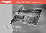
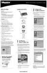
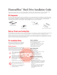
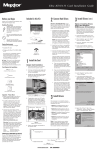
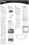
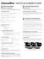
DiamondMax Hard Drive Installation Sheet 1 Before You Begin 2 General Requirements IMPORTANT – PLEASE READ! BIOS Requirements Please read this Installation Sheet completely before installing the Maxtor hard drive. It gives general information for installing a Maxtor hard drive in a typical computer system. If you don’t understand the installation steps, have a qualified computer technician install the hard drive. System BIOS dated prior to September 1997 do not support drives greater than 8.4 GB. To obtain the full capacity of a drive larger than 8.4 GB, upgrade the BIOS, install a BIOS enhancer card or use the MaxBlast installation software (version 9.06 or newer). Handling Precautions Ultra Direct Memory Access (UDMA) If the handling precautions are not followed, damage to the hard drive may result – which may void your warranty. See the Warranty section for additional information. ◆ Allow the hard drive to reach room temperature BEFORE installing it in your computer system. ◆ Hard drives are sensitive to electrostatic discharge (ESD) damage. Handle the drive by its sides. DO NOT touch the printed circuit board. ◆ NEVER drop, jar, or bump the drive. ◆ DON’T connect/disconnect any drive cables when the power is on. ◆ DON’T force or rock the hard drive connectors into or out of their connection sockets. 3 Hard Drive Identification IDE stands for Integrated Drive Electronics and EIDE is Enhanced IDE. The IDE or EIDE interface is designed to support two devices – typically hard drives – on a single ribbon cable through one 40 pin connector on the mother board or interface card. Some mother boards and interface cards may have a second IDE/EIDE connector to support two additional IDE devices. The IDE/EIDE interface is identified as a primary or secondary interface. In systems with only a single connector on the mother board or interface card, it is the primary IDE/EIDE interface. To add a second IDE/EIDE interface requires a special interface card. In systems with two connectors on the mother board or interface card, one is the primary and the other as the secondary. The primary interface must be used for at least one IDE device before connecting any devices to the secondary IDE interface. System Requirements ◆ ◆ UDMA mode on a Maxtor hard drive will only activate when the drive is installed in a system with full UDMA capability, i.e., a mother board or interface card with the UDMA chips and the associated UDMA software drivers DiamondMax hard drives that carry a “U” in the model number are UltraDMA 66 (UDMA, Mode 4) compatible. For UDMA 66 data transfers, a UDMA 80-conductor cable is required. IDE/AT interface Maxtor recommends: • Drives less than or equal to 8.4 GB: - 486 DX 66 MHz • Drives larger than 8.4 GB: - Pentium-class processor Operating System Requirements • Drives less than or equal to 8.4 GB: DOS 5.0 or higher • Drives larger than 8.4 GB: √ Installing as boot drive (Primary Master) requires full installation set of Windows 95/98 – not an upgrade from DOS or Windows 3.x. √ Installing as non-boot drive (Primary Slave, Secondary Master or Slave) requires full installation set of Windows 95/98 on the boot drive. Tools for Installation The following tools are needed to install your new Maxtor hard drive: ◆ A small Phillips head screw driver ◆ Your computer user’s manual ◆ Small needle-nose pliers or tweezers ◆ Operating system software Ribbon cable lengths are limited to 18 inches and have two or three 40 pin connectors. IDE devices may be connected anywhere on the cable. One connector is attached to the IDE connector on the mother board or interface card and the remaining connector(s) are available for the IDE devices. Identifying IDE Devices on the Interface Each device must be identified as either the Master or Slave device on that interface (cable). Each cable must have a Master before it can have a Slave device on the cable. There cannot be two Master or two Slave devices on the same cable. IDE devices use jumpers to designate the Master/Slave identification of the device. Each manufacturer may have its own jumpering scheme to identify the device as a Master or Slave and its relationship to other IDE devices attached to the same cable. Jumper Settings A jumper is a small piece of plastic that slides over a pair of configuration pins on the drive to activate a specific function. The jumper illustration below shows three valid jumper settings for Maxtor hard drives – Master, Slave and Cable Select. Maxtor hard drives can be set as either a Master or a Slave device. There are no other jumpers to set when the Maxtor drive is installed on the same ribbon cable with another IDE device. Drive Identification Information Copy the following information from the label on the top cover of the Maxtor hard drive for future reference: Model Number ________________ Serial Number _________________ HDA Uplevel _______ PCBA Uplevel _______ Unique Uplevel _______ Cylinders _________ Heads _________ Sectors _________ Capacity Barriers Due to operating system limitations, DOS cannot access the full capacity of drives larger than 8.4 GB. The Microsoft Windows 95 operating system or equivalent (full installation), NOT a Windows 95 upgrade from DOS (Windows 3.1 or 3.11), is required to obtain the full capacity of any hard drive larger than 8.4 GB. Back up. Protect Your Existing Data Periodic backup of important data is always a good idea. Whenever your computer is on, there is the potential for losing data on your hard drive. This is especially true when running disk utilities or any software that directly manipulates your files. Maxtor recommends that you make a backup copy of the files on any existing hard drives. If required, this data may then be copied to the Maxtor hard drive after it has been installed in the computer. Refer to your computer user’s manual for detailed data backup instructions. Rear View of Maxtor Hard Drive Master, Slave and Cable Select Settings Before installing the drive in the computer, you must determine how the jumpers on the Maxtor hard drive are to be set for your system based upon the use of the Maxtor hard drive as either a Master or Slave device. Maxtor hard drives are shipped with the Master jumper setting enabled. 5 IMPORTANT: If a Maxtor hard drive is being added to a system on the same cable with an existing IDE device, it may be necessary to re-configure the jumpers on the existing device to insure that the system will properly recognize both devices. Information regarding the correct jumper configurations on other IDE devices is available in their product documentation or from the manufacturer of that device. In order for the computer to recognize the Maxtor hard drive is in the system, the power cable and IDE interface cable must be properly connected. Systems Using Cable Select IMPORTANT: Most systems do not use this feature. Unless you are sure that your computer system supports Cable Select, do not set up the drive with this feature enabled. Maxtor hard drives support Cable Select. The Cable Select method of drive identification allows the system to identify Master and Slave IDE devices based upon the position (connector) the IDE device is attached to on the interface (ribbon) cable. On Maxtor hard drives, Cable Select is enabled by adding a jumper to J48. Attaching IDE Interface and Power Cables 1 Attach an IDE interface connector to J1 on the Maxtor hard drive. The striped or colored edge of the IDE interface cable indicates pin 1. Pin 1 on the IDE interface cable connector must match pin 1 on the Maxtor hard drive IDE interface connector – closest to the drive power connector. It must also match pin 1 on the IDE connector on the mother board or IDE interface card. Refer to the system or interface card user’s manual for identification of pin 1 on their IDE interface connector. 2 Connect an available power connector to J2 on the Maxtor hard drive. This connector is keyed and will only fit in one orientation. Do not force or rock the connector. A special IDE cable select interface cable is required for systems using the Cable Select feature. If your system supports this feature, refer to the system user’s manual or contact the system manufacturer for specific procedures for installing hard drives. After attaching the IDE interface cable and the power cable to the Maxtor hard drive, verify that all other cables connected to other devices, the mother board or interface card(s) are correctly seated. Relationship to Other IDE Devices Maxtor recommends that its hard drives be configured as a Master device to any IDE device that is not a hard drive (e.g., CD-ROM’s, Tape drives, Zip drives etc.). 4 Mounting Drive in System Turn the computer OFF, disconnect the power cord and remove the cover. Refer to the computer user’s manual for information on removing the cover. Each system manufacturer uses different types of cases, including desktop, mini- and fulltower configurations. As a result, there are many different possible mounting locations that could be used. Striped/colored edge is pin 1 Rear View of Maxtor Hard Drive IDE Interface and Power Connections In a typical system case, there are specific 3.5 inch and 5.25 inch bays available for storage devices. When a 3.5 inch mounting bay is available, mounting brackets are not required. If a 5.25 inch mounting bay is used, mounting brackets will be required to mount the Maxtor hard drive in the system case. Refer to the system manufacturers user’s manual or contact the system manufacturer directly for additional information. Installing 5.25-inch Mounting Brackets and Rails If the Maxtor hard drive is being mounted in a 5.25 inch drive bay, the following figure shows how to attach the brackets to the drive. The brackets are not required when mounting in a 3.5 inch drive bay. 6 Attaching System Cables The computer system the Maxtor hard drive is being installed in will have its own cable placement and connection methods. This means that the location of the IDE interface connectors on the mother board and/or interface card and the orientation of pin one is determined by the manufacturer. Also, older systems and interface cards may have only a single IDE interface connection – limiting the system to two IDE devices. Refer to the system or interface card user’s manual for cable connection and orientation instructions. Attach the 40-pin IDE interface cable from the Maxtor hard drive to the IDE connector on the mother board or IDE interface card. Insure that the red edge of the ribbon cable is oriented to pin 1 on the interface. Hard Drive with 5.25-inch Mounting Brackets NOTE: When installing a UDMA 66 DiamondMax Hard Drive (model numbers designated with a “U”), an 80 conductor cable must be used. Please use the following connection steps; 1) the blue connector must be attached to the system IDE interface; 2) the gray connector must be attached to Device 1 (slave), and 3) the black connector must be attached to Device 0 (master). Installing in a Device Bay After the hard drive is prepared with mounting brackets, if required, and the jumpers are set correctly, the drive can be mounted in a device bay and secured. Be sure to secure the drive with all four screws in the device bay. This provides grounding and protection from shock and vibration. NOTE: Computer systems use different methods for mounting hard drives. Please refer to the computer user’s manual or contact the manufacturer for specific mounting instructions. UDMA 66 Interface Cable 7 System Setup If the system correctly detects the drive and does not hang during the boot process, proceed to Section 8. If the system hangs during the POST, proceed to Section 9. If Auto Detect did not find the drive and no error message was presented, proceed to step 2 below. The following procedures are designed for systems using the DOS 5.0 (or higher), Windows 95/98 OS’s. For other operating systems (e.g., Windows NT, OS2, UNIX, LINUX and Novell NetWare), refer to the OS user’s manual for the BIOS setting and other installation requirements. For drives with capacities larger than 8.4 GB, the full installation set for Windows 95A or 95B (OSR2) and Windows 98, is required. OS’s that do not support extended interrupt 13 cannot access or format a drive larger than 8.4 GB. This is true regardless of BIOS, mother board or interface card support. DOS based OS’s do not support this interrupt and are limited to a maximum drive size of 8.4 GB. It is not possible to upgrade from a DOS OS to Windows 95/98 and obtain the full capacity of a drive larger than 8.4 GB. 2 Enter the BIOS menu where the hard drive definitions are displayed and select the appropriate entry (Primary Master, Primary Slave, Secondary Master or Secondary Slave – or their equivalents) for the Maxtor hard drive. If the SETUP program does not provide an AUTO DETECT capability, the drive parameters must be set using the User Definable Type (UDT). Set the Cylinder, Head and Sector values with the values listed on the drive label. The drive label is located on the top cover of the drive. The fields LZone (Landing Zone) and WPcom (Write Pre-comp) are not used by the Maxtor hard drive. These fields may be set to 0 or by the values assigned by the BIOS. Setting the BIOS (CMOS) The SETUP (BIOS) program identifies the system information (e.g., floppy drives, hard drives, video, etc.) used to identify devices attached to the computer during system boot. This includes the information about what kind and how many IDE hard drives are attached to the system. NOTE: Each BIOS manufacturer uses different methods of identifying the UDT. Newer BIOS’ from all manufacturer’s will usually include an entry called “User” or “User 1.” Older BIOS’ vary in the method used to identify the UDT. Following are examples of BIOS UDT: AMI = Type 47, Award = Type 47 and Phoenix = Type 48 IMPORTANT: Major BIOS manufacturers like AMI, Award and Phoenix provide their core BIOS programs to system board manufacturers and OEM’s who have the capability of making modifications to some of the descriptions and definitions to meet their unique requirements. These changes include how to access the BIOS, the appearance of the information on the screens and the location of parameters within the BIOS. Refer to the system or BIOS manufacturers documentation help on entering the BIOS setup program for your computer. Only the cylinder, head and sector values printed on the drive label must be entered. All other values may be zero (0). Set the LBA mode to enabled for this drive. Refer to the system user’s manual or contact the system manufacturer for information on enabling LBA. WARNING: When entering settings for the Maxtor hard drive, be careful not to change any of the other BIOS settings, or other parts of the system may not work correctly. If the SETUP program does not provide the UDT, set the BIOS to the drive type with the largest capacity of those listed in the BIOS. BIOS (CMOS) Parameters In order for the computer system to recognize the new Maxtor hard drive, it is necessary to set the system BIOS with the correct information about the drive. To do this, run the system SETUP (BIOS) program. The Maxtor hard drive must be identified to the system through the BIOS and it must be registered in the BIOS based upon its position relative to the other IDE devices connected to the system and recorded in the BIOS. Most newer BIOS’ provide the descriptions of Primary Master, Primary Slave, Secondary Master and Secondary Slave (see section 2) which identify the device configuration and location on an IDE interface and its relationship to the other IDE devices on the same interface or ribbon cable. Some older BIOS versions do not use this terminology for identification and it may be necessary to refer to the system user’s manual or BIOS documentation to determine where the drive settings should be set in that specific BIOS. If this information is not available, then it will be necessary to contact the system manufacturer for the correct terminology to correctly identify the drives within the system. The following are the typical steps to be used to set the hard drive parameters in a BIOS: A Turn the system ON. During the system start-up sequence, run the SETUP (BIOS) program or similar commands to access the system BIOS. NOTE: Newer systems will typically display a message (e.g., press DEL to Enter Setup) identifying how to access the SETUP (BIOS) program. B Once the SETUP (BIOS) program is active, do one of the following to set the BIOS parameters for the Maxtor hard drive. 1 Enter the BIOS menu where the hard drive settings are displayed, select the correct entry (Primary Master, Primary Slave, Secondary Master or Secondary Slave or their equivalents) to set the parameters for the Maxtor hard drive. If the SETUP program provides an “AUTO DETECT” capability, use this feature to detect the Maxtor hard drive. If the SETUP program does not have AUTO DETECT, set the drive parameters as defined in step 2. Typically, this feature is available for each individual IDE device. It may be necessary to exit the BIOS, re-boot the system and reenter the BIOS before the AUTO DETECT operation will take effect. IMPORTANT: After the SETUP program has detected the hard drive, verify that the Logical Block Addressing (LBA) mode is enabled for the drive - as not all BIOS versions set this feature during the AUTO DETECT process. COMMENT: When LBA is enabled, some BIOS programs (typically Award) will change the values of the cylinders and heads by dividing the cylinders by 2, 4, 8 or 16 and multiplying the heads by the same value. This operation will not change the capacity of the hard drive. C After the drive parameters are entered, follow the SETUP program procedures to save the settings and exit the SETUP program. After changing BIOS settings, saving the values and exiting, the SETUP program should force the system to re-boot. If you are not sure how the UDT is defined in the BIOS, refer to the computer user’s manual or contact the system manufacturer. 8 Hard Drive Preparation To finish the installation, the drive must be partitioned and formatted. Hard drive partitioning and formatting may be done with the operating system software or with MaxBlast installation software. Select A or B below to complete the preparation of the Maxtor hard drive. NOTE: Drive letter assignment is controlled by the operating system and not by the BIOS or MaxBlast. The operating system assigns drive letters to all devices as follows: (1) to all hard drives and their partitions; (2) to all other devices like CD-ROM’s and tape drives. When adding an additional hard drive to the system, the drive letters will be automatically changed by the operating system. A Preparing the hard drive using the operating system software. IMPORTANT: Due to operating system limitations, DOS operating systems cannot access the full capacity of drives larger than 8.4 GB. The Windows 95 full installation, not an upgrade from DOS, operating system or equivalent is required to obtain the full capacity of any drive larger than 8.4 GB. If the system or interface card correctly supports the Maxtor hard drive, the drive may be partitioned and formatted using the OS software. If the cylinder limitation jumper (J46) is installed or the BIOS does not support the hard drive, the MaxBlast installation software (option B below) must be used to prepare the hard drive. Certain OS’s (e.g., Windows NT, Novell) do not support this option. You will have to install the drive on a system that has a BIOS that supports the capacity of the drive when installing these OS’s. NOTE: All versions of DOS, PC-DOS, DR-DOS and Windows 95A (FAT 16 support) have a partition size limitation of 2.1 GB. For drives larger than 2.1 GB, the drive must be divided into partitions that do not exceed the 2.1 GB limitation. Windows 95B and 98 (OSR2) do not have this limitation. Windows NT, OS2, UNIX, LINUX and Novell NetWare may have different limitations but please refer to their documentation or contact the manufacturer for verification. For detailed operating system installation assistance, refer to the system manufacturers user’s manual, the OS user’s manual or contact the manufacturer directly. B Preparing the hard drive using MaxBlast installation software. 1 Boot the system with the bootable MaxBlast software installation diskette. 2 The MaxBlast installation software will load and the first screen of the program will display. Follow the on-screen prompts to complete the hard drive installation. 9 System Hangs During Boot If the system hangs during the boot process after installing the Maxtor hard drive – either before or after setting the system BIOS – the system many have a BIOS with a cylinder limitation. This may occur for hard drives that exceed 2.1 GB. If this happens, do the following: 1 Turn the system OFF. 2 Install the cylinder limitation jumper (J46) on the drive. The figure below shows the Maxtor hard drive configured as a Master or Slave device with the cylinder limitation jumper installed. IMPORTANT: When the Cylinder Limitation jumper (J46) is installed, the Maxtor hard drive must be prepared using MaxBlast installation software. Certain OS’s (e.g., Windows NT, Novell) do not support this option. You will have to install the drive on a system that has a BIOS that supports the capacity of the drive when installing these OS’. Limited Warranty Statement Maxtor’s warranty obligations are limited to the terms set forth: Maxtor warrants to the original consumer purchaser that new Maxtor products will be free from defects in material and workmanship for 3 years from the date of original purchase. For replacement disk drives the warranty on the replacement drive is the remainder of the warranty on the original drive or 90 days, whichever is longer. For disk drives obtained under the Maxtor Upgrade Program, the warranty period is 3 years commencing on the date Maxtor ships the drive to the customer. If you discover a defect, Maxtor will, at its option, repair or replace the product at no charge to you, provided you return it during the warranty period, with transportation charges prepaid, to Maxtor in San Jose, CA; Bray, Ireland or Singapore. Drives must be properly packaged in Maxtor packaging or Maxtor approved packaging to obtain warranty service. Before returning a Maxtor product, please contact Maxtor at 1-800-2MAXTOR and press option 2 (IN USA) to obtain a Return Material Authorization (RMA) number. A copy of the receipt or a bill of sale bearing the appropriate Maxtor serial number and model number may be required for warranty service. The warranty applies only to the Maxtor products that can be identified by the Maxtor trademark, trade name or logo affixed to them. Maxtor does not warrant any product that is not manufactured by, for or with permission from Maxtor. This warranty is not applicable to; • Abnormal wear and tear • Abuse, unreasonable use, mistreatment, or neglect • Damage caused during installation of the disk drive • Damage caused by the equipment or system with which the disk drive is used • Damage caused by modification or repair not made or authorized by Maxtor • Disk drives whose Maxtor Serial Number has been removed or defaced • Damage caused by use of non-Maxtor packaging • Damage caused by improper or improperly used packaging • Damage caused by lack of ESD protection • Drives that are determined to be stolen. THIS WARRANTY AND REMEDIES SET FORTH ABOVE ARE EXCLUSIVE AND IN LIEU OF ALL OTHERS, WHETHER ORAL OR WRITTEN, EXPRESSED OR IMPLIED. MAXTOR SPECIFICALLY DISCLAIMS ANY AND ALL IMPLIED WARRANTIES, INCLUDING, WITHOUT LIMITATION, WARRANTIES OF MERCHANTABILITY AND FITNESS FOR A PARTICULAR PURPOSE AND AGAINST INFRINGEMENT. NO MAXTOR DEALER, AGENT OR EMPLOYEE IS AUTHORIZED TO MAKE ANY MODIFICATION, EXTENSION OR ADDITION TO THIS WARRANTY. MAXTOR IS NOT RESPONSIBLE FOR SPECIAL, INCIDENTAL, INDIRECT OR CONSEQUENTIAL DAMAGES RESULTING FROM ANY BREACH OF WARRANTY, OR UNDER ANY OTHER LEGAL THEORY, INCLUDING BUT NOT LIMITED TO LOSS OF DATA, LOSS PROFITS, DOWNTIME, GOODWILL, DAMAGE OR REPLACEMENT OF EQUIPMENT AND PROPERTY, AND ANY COSTS OF RECOVERING, PROGRAMMING OR REPRODUCING ANY PROGRAM OR DATA STORED IN OR USED WITH MAXTOR DISK DRIVES. Some states do not allow the exclusion or limitation of incidental or consequential damages or exclusions of implied warranties, so the above limitations or exclusions may not apply to you. This warranty gives you specific legal rights, and you may also have other rights that vary from state to state. Contacting Maxtor’s Customer Support Center 1-800-2-MAXTOR (1-800-262-9867) Agents available from 6 a.m. to 6 p.m. (mountain time) Monday through Friday. Rear View of Maxtor Hard Drive Master, Slave and Cable Select Settings with Cylinder Limitation Enabled 3 If the BIOS was set to AUTO DETECT, follow the instructions in Section 7 to prepare the hard drive using the MaxBlast installation software. If other BIOS settings were used, access the system BIOS SETUP program and set the parameters to a User Definable Type with 4,092 cylinders, 16 heads and 63 sectors per track for the Maxtor hard drive. Then follow the instructions for setting the BIOS in Section 7 then Section 8 to prepare the hard drive with MaxBlast software. Press 1 Press 2 Press 3 • Technical Support Installation and Troubleshooting Assistance • MaxInfo - 24-hour Automated Voice Troubleshooting System • • • • • MaxFax™ 24-hour Automated Fax Retrieval Service Customer Service Replacement Options Warranty and RMA Status 24-hour Automated Customer Service Information Contacting Maxtor Outside the U.S. /Canada Customer Support Center MaxInfo MaxFax™ 303-678-2015 303-678-2015, press 1 303-789-2618 Maxtor on the Internet Home Page FTP Site http://www.maxtor.com ftp://ftp.maxtor.com Fax and E-mail How to Obtain MaxBlast Software If a MaxBlast software installation diskette was not included with the hard drive, the MaxBlast software may be downloaded from Maxtor’s Internet home page at http:// www.maxtor.com. MaxBlast must be downloaded to a hard drive already prepared for use with an OS. The instructions for creating the MaxBlast bootable diskette are available for viewing and printing from the MaxBlast download page. Technical Support Fax 303-678-2260 Customer Service Fax 408-922-2085 Technical Support E-mailvisit Maxtor’s web site and follow links Customer Service E-mail visit Maxtor’s web site and follow links Copyright © 1999 Maxtor Corporation. 800-262-9867. Contents and specifications subject to change without notice. DiamondMax™ is a trademark of Maxtor Corporation. Maxtor Part # 1417/A