1
QUAD
Analogue/Digital Input Module
for Motion Sensors, Temperature Probes and Binary Inputs
Application program version: [5.1]
User manual edition: [5.1]_c
www.zennio.com
USER MANU AL
ZN1IO-4IAD
QUAD
Contents
Document Updates ................................................................................................................... 3
1
2
3
Introduction ...................................................................................................................... 4
1.1
QUAD ........................................................................................................................ 4
1.2
Installation ................................................................................................................ 5
Configuration .................................................................................................................... 7
2.1
General...................................................................................................................... 7
2.2
Security Binary Inputs ................................................................................................ 8
2.3
Thermostats ............................................................................................................ 11
ETS Parameterisation ...................................................................................................... 12
3.1
Default Configuration .............................................................................................. 12
3.2
General Screen ........................................................................................................ 12
3.2.1
Binary Input ................................................................................................. 13
3.2.2
Temperature Probe...................................................................................... 24
3.2.3
Motion Detector .......................................................................................... 26
3.3
Thermostats ............................................................................................................ 27
ANNEX I. Communication Objects ........................................................................................... 28
http://www.zennio.com
Technical Support: http://zennioenglish.zendesk.com
2
QUAD
DOCUMENT UPDATES
Version
Changes
Page(s)
[5.1]_b / c
Revision about the “Light ON/OFF (switched)” option in the
Dimmer Control function of the Push Button.
16 - 18
Changes in the application program:
• Thermostat: possibility of periodically sending, if
configured, the control variable of the currently inactive
mode (parameter: “Send both H/C control signals
periodically?”).
• Thermostat: restriction to prevent sending
additional heat/cool orders when they are
necessary.
the
not
-
• Motion sensor: new parameter to restart the luminosity
for a certain time after a no-detection.
New structure of the section.
[5.1]_a
4
Clarifications and figures added.
Figures 11, 12, 15, 16, 17, 19 and 21 added.
8-10
-
Clarification about the Shutter controls.
15-16
Clarification and examples about the Light Dimming.
16-19
Clarification about the Lock function.
23
Clarification and example added about how the initial states
are sent.
24
Clarification about the “channel” concept.
27
General revision of the document – texts and styles.
-
Changes in the application program:
[5.0]_a
http://www.zennio.com
• Security function added to the switch/sensor binary
inputs to allow the detection of breakdown / sabotage
situations.
-
Technical Support: http://zennioenglish.zendesk.com
3
QUAD
1 INTRODUCTION
1.1 QUAD
QUAD is an analogue / digital input module from Zennio featuring four separate inputs,
each configurable as:
Binary Input.
Inputs configured as binary inputs can be connected a conventional,
potential-free pushbutton, a switch or a binary sensor.
It is also possible to detect breakdown and sabotage situations in the input
lines by enabling the security functions for the binary inputs.
Temperature Probe.
Inputs configured as a temperature probe can be connected a temperature
sensor (such as model ZN1AC-NTC68 from Zennio), which will allow QUAD
monitor the room temperature.
Motion Detector.
Inputs configured as motion detectors need to be connected a Zennio motion
sensor (model ZN1IO-DETEC), which will allow QUAD monitor presence or
luminosity changes in a room.
Moreover, QUAD implements four independent thermostats, which can be enabled
and configured separately.
Figure 1. QUAD
http://www.zennio.com
Technical Support: http://zennioenglish.zendesk.com
4
QUAD
1.2 INSTALLATION
QUAD is connected to the KNX bus through the incorporated terminal connector, while
the input lines need to be connected to QUAD through the screw terminal block,
bundled with the packaging of the device.
Once powered through the KNX bus, the device may be downloaded both an individual
address or the application program.
Figure 2 shows the connection diagram of QUAD.
1.- KNX Bus Connector
2.- Programming LED
3.- Programming Button
4.- Slot for the Input Lines
Figure 2. Element diagram
The main elements are described next:
Programming Button: a short press on this button sets the device into the
programming mode, making the associated LED (2) light in red. If this button
is held at the same time of applying bus power to the device, QUAD will enter
the Safe Mode. In such case, the LED will intermit in red.
Slots for the Input Lines: insertion slot for the input terminal block (Figure
3), which is required for the connection of the input lines (1-4) to QUAD. For
proper results, the terminals from the external elements (pushbutton, switch,
sensor, temperature probe or motion sensor) should be connected on the one
hand to the corresponding numbered connection point (1-4) of the terminal
block, and on the other hand to any of the two common connection points
(labeled as “C”), which are internally connected, which makes them
equivalent to each other.
http://www.zennio.com
Technical Support: http://zennioenglish.zendesk.com
5
QUAD
Figure 3. Input terminal block
To obtain further information about the technical features of QUAD and on security
and installation procedures, please refer to the Datasheet of the device, bundled
with the original packaging and also available at the http://www.zennio.com
website.
http://www.zennio.com
Technical Support: http://zennioenglish.zendesk.com
6
QUAD
2 CONFIGURATION
2.1 GENERAL
The QUAD analogue/digital input controller from Zennio is a multi-function device
featuring four input ports, each of them configurable as:
Binary Input,
Temperature Probe,
Motion sensor.
Therefore, QUAD makes it possible to connect different external elements as long as
they match any of the above categories: pushbuttons, switches, temperature probes,
motion sensors (model ZN1IO-DETEC from Zennio)…
Inputs configured as binary should be distinguished into pushbuttons and
switches/sensors (depending on the connected element). Each of these two have
their own configurable parameters, as described in section 3 of this manual.
Inputs configured as temperature probes can be customised through a set of
parameters related to how the temperature value is measured and sent to the bus.
On their side, inputs configured as motion sensors offer up to three virtual channels
each, which allows performing different actions upon detection and no-detection events
on the corresponding input. As a result of the motion detection / no-detection, each
channel will send the corresponding objects to the KNX bus, unless the channel is
found to be locked.
The motion sensor also features a luminosity sensor, which may be configured in
QUAD to send the detection / no-detection objects depending on the measured
luminosity level and according to the previously calibrated levels.
http://www.zennio.com
Technical Support: http://zennioenglish.zendesk.com
7
QUAD
2.2 SECURITY BINARY INPUTS
Binary inputs configured as an switch / sensor offer the option to enable a security
function, in order to detect breakdown or sabotage events that may arise in the system.
This security function relies on the insertion of an end-of-line resistor, and on
continuously monitoring the state of such line, so any unexpected situation can be
detected.
Important: any of the resistors shown in Table 1 can be installed, although it is
advisable that the power permitted by the resistor (manufacturers and vendors typically
provide with this information) is at least 0.25 W. Note that the value of the selected
resistor should be also set by parameter in ETS.
Value (Ohms)
Minimum recommended power (W)
2200 Ω (±10%)
2700 Ω (±10%)
3300 Ω (±10%)
¼W
4700 Ω (±10%)
10000 Ω (±10%)
Table 1. End-of-line resistor permitted values
Two different use cases can be distinguished:
Normally Closed (N.C.) Switch / Sensor: the circuit remains typically closed
and is only opened in the event of an interruption or a detection in the sensor.
The selected resistor should be connected to the circuit line in series, and as
closer as possible to the switch/sensor, preferably in touch with its terminals
and hardly accessible from outside. See Figure 4.
N.C. S/S
Figure 4. Normally closed switch/sensor. Resistor in series
In the event of a short-circuit in the line, QUAD will set the alarm object of
the corresponding input to “1”, and will then send it periodically to the bus
http://www.zennio.com
Technical Support: http://zennioenglish.zendesk.com
8
QUAD
until the situation is over, as the short-circuit is interpreted to be due to a
sabotage or a breakdown.
N.C. S/S
Figure 5. Short-circuit (normally closed S/S)
In the event of an open circuit in the line, QUAD will interpret it as a
regular falling edge (i.e., as an interruption or a detection in the
switch/sensor), so only the value parameterised for such edge will be sent
to the bus.
N.C. S/S
Figure 6. Open circuit (normally closed S/S)
Normally Open (N.O.) Switch / Sensor: the circuit remains typically open
and only becomes closed in the event of an interruption or a detection in the
switch/sensor. The selected resistor should be connected to the circuit line in
parallel, and as closer as possible to the switch/sensor, preferably in touch
with its terminals and hardly accessible from outside. See Figure 7.
N.O. S/S
Figure 7. Normally open switch/sensor. Parallel resistor
In the event of a short-circuit in the line, QUAD will interpret it as a
regular rising edge (i.e., as an interruption or a detection in the
http://www.zennio.com
Technical Support: http://zennioenglish.zendesk.com
9
QUAD
switch/sensor), so only the value parameterised for such edge will be sent
to the bus.
N.O. S/S
Figure 8. Short-circuit (normally open S/S)
In the event of an open circuit in the line, QUAD will set the alarm object
of the corresponding input to “1”, and will then send it periodically to the
bus until the situation is over, as the open circuit is interpreted to be due to
a sabotage or a breakdown.
N.O. S/S
Figure 9. Open circuit (normally open S/S)
By means of this security function in the switch/sensor binary inputs, QUAD is also able
to analyse the voltage levels of the system. In case they are found to be unstable
(e.g., due to the coupling of other lines), QUAD will activate the alarm object of the
corresponding input and send the activation value to the bus periodically, until such
event is over.
Additionally, QUAD offers the possibility of connecting multiple switches / sensors to
the same input (so that a certain function can be alternatively controlled from one or
another), provided that they are of the same type: normally open or normally closed. In
case this option needs to be combined with the security function, it is important to keep
in mind that only one end-of-line resistor should be installed (in other words: only to
one of the switches / sensors connected to the same input).
http://www.zennio.com
Technical Support: http://zennioenglish.zendesk.com
10
QUAD
2.3 THERMOSTATS
QUAD allows independently enabling and configuring up to four thermostat functions,
with independence of the number of the inputs that have been configured.
How the Zennio thermostat works and is configured is described in an specific
document, Zennio Building Thermostat, available at the http://www.zennio.com
website.
http://www.zennio.com
Technical Support: http://zennioenglish.zendesk.com
11
QUAD
3 ETS PARAMETERISATION
To begin with the parameterisation process of QUAD it is necessary, once the ETS
software has been opened, to import the corresponding product database.
Next, the device is inserted into the project where desired and, after right-clicking on its
name, the “Edit parameters” option should be selected to start the process.
The next sections show the parameterisation process in detail, and the different
functions provided by QUAD.
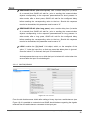
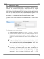
3.1 DEFAULT CONFIGURATION
When entering the parameter edition of QUAD for the first time, the following window
will be shown:
Figure 10. Default parameterisation window
As shown in Figure 10, the four inputs of the device are disabled by default. It is
necessary to enable and configure them independently.
The Thermostats tab is also visible by default. It permits enabling and configuring the
four available thermostats, which are disabled by default.
No communication objects are displayed by default. They will become visible as the
different functions of the device are enabled by the integrator.
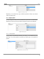
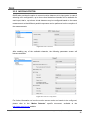
3.2 GENERAL SCREEN
This window brings the option to enable and configure the different input ports of
QUAD.
http://www.zennio.com
Technical Support: http://zennioenglish.zendesk.com
12
QUAD
Figure 11. Enabling an input
Depending on the selected input type, additional parameter windows may become
visible, as explained next.
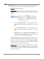
3.2.1 BINARY INPUT
An input configured as binary can be connected both a push button or a switch/sensor.
Depending on the binary input type, different configuration options will be displayed.
Figure 12. Binary input
3.2.1.1 PUSH BUTTON
From the specific tab enabled after selecting “push button” for the enabled binary input
(see Figure 13) it will be possible to customise how QUAD reacts on the detection of
presses.
Figure 13. Binary input: push button
http://www.zennio.com
Technical Support: http://zennioenglish.zendesk.com
13
QUAD
SHORT PRESS: sets the type of the action to be performed when a short
press takes place on the push button connected to the input of QUAD:
No Action. No action is performed.
Sending of 0/1. A new tab becomes visible to let the integrator set (under
“Response”) the value to be sent to the KNX bus when a short press
happens:
Figure 14. Sending of 0/1
•
“0”: the “[Ix] [Short Press] 0” 1-bit communication object is
enabled, and sent to the KNX bus (with the value “0”) on every
press.
•
“1”: the “[Ix] [Short Press] 1” 1-bit communication object is
enabled, and sent to the KNX bus (with the value “1”) on every
press.
•
“Switching 0/1”: the “[Ix] [Short Press] Switching” 1-bit
communication object is enabled, and sent to the KNX bus with
the values “1” and “0” alternating after every press.
The transmission of these values can be performed cyclically, i.e., it is
possible to periodically re-send them (the 0s, or the 1s, or both) if
configured. If such option is required, the “Cyclical Response Sending”
parameter needs to be enabled, which will bring an additional parameter
(“Cycle time”) to set a certain time (1-255 seconds).
Shutter Control. This function allows sending the KNX bus a 1-bit object
for shutter control. Under the “Response” parameter in the tab that shows
up after selecting this function, it is possible to select the particular order to
be sent on a short press:
http://www.zennio.com
Technical Support: http://zennioenglish.zendesk.com
14
QUAD
Figure 15. Shutter control
•
Up: the “[Ix] [Short Press] Move Up Shutter” 1-bit object is enabled,
and sent to the KNX bus (with the value “1”) so that the shutter is
moved up.
•
Down: the “[Ix] [Short Press] Move Down Shutter” 1-bit object is
enabled, and sent to the KNX bus (with the value “0”) so that the shutter
is moved down.
•
Up/down (switched): the “[Ix] [Short Press] Move Up/Down Shutter”
1-bit object is enabled, and sent to the KNX bus with the values “1” and
“0” alternating, so the move up and move down orders can be sent with
a sole push button.
•
Stop/Step Up: the “[Ix] [Short Press] Stop/Step Up Shutter” 1-bit
object is enabled, and sent to the KNX bus (with the value “0”) in order
to stop the shutter. In case the shutter is not in motion and if slats /
lamellas are available, this value will be interpreted as an order to move
them one step upwards.
•
Stop/Step Down: the “[Ix] [Short Press] Stop/Step Down Shutter” 1bit object is enabled, and sent to the KNX bus (with the value “1”) in
order to stop the shutter. In case the shutter is not in motion and if slats
/ lamellas are available, this value will be interpreted as an order to
move them one step downwards.
•
Stop/Switched Step: the “[Ix] [Short Press] Stop/Step Shutter
(switched)” 1-bit object is enabled, and sent to the KNX bus (with the
values “1” and “0” alternating with every press) in order to stop the
shutter. In case the shutter is not in motion and if slats / lamellas are
available, this value will be interpreted as an alternating order to move
them one step downwards or upwards.
http://www.zennio.com
Technical Support: http://zennioenglish.zendesk.com
15
QUAD
Dimmer Control. This functions allows sending the KNX bus a
communication object to control light-dimming devices. Under the
“Response” parameter in the tab enabled after selecting this function, it is
possible to set the particular order to be sent:
Figure 16. Dimmer
•
Light ON: the “[Ix] [Short Press] Dimmer ON” 1-bit object is enabled,
and sent to the KNX bus (with the value “1”) so that the light is turned
on by the dimmer.
•
Light OFF: the “[Ix] [Short Press] Dimmer OFF” 1-bit object is
enabled, and sent to the KNX bus (with the value “0”) so that the light is
turned off by the dimmer.
•
Light ON/OFF (switched): the “[Ix] [Short Press] Dimmer ON/OFF”
1-bit object is enabled, and sent to the KNX bus with the values “1” and
“0” alternating with every press, so that the light can be turned on and
off with a sole push button.
Note: this function works in the same terms both if applied to short
presses or to long presses: every time a button press is detected, a
different order will be sent (switch-on / switch-off), while no orders will
be sent at all when the button is released.
•
Brighter: the “[Ix] [Short Press] Brighter” 4-bit object is enabled, and
sent to the KNX bus so that the light level is increased by the
parameterised step (“Dimming step” parameter, according to Table 2).
On the first short press, a light increase order will be sent, while on the
second press an order to interrupt the regulation will be sent. Further
presses will repeat the same sequence.
http://www.zennio.com
Technical Support: http://zennioenglish.zendesk.com
16
QUAD
Dimming step
Presses required for the
entire regulation (0% – 100%)
100%
1
50%
2
25%
4
12,5%
8
6,25%
16
3,1%
32
1,5%
64
Table 2. Dimming steps
•
Darker: the “[Ix] [Short Press] Darker” 4-bit object is enabled, and
sent to the KNX bus so that the light level is decreased by the
parameterised step (“Dimming step” parameter, according to Table 2).
On the first short press, a light decrease order will be sent, while on the
second press an order to interrupt the regulation will be sent. Further
presses will repeat the same sequence.
•
Brighter/Darker (switched): the “[Ix] [Short Press] Brighter/Darker”
4-bit object is enabled, and sent to the KNX bus alternatively with the
orders to increase or to decrease the light level by the parameterised
step (“Dimming step” parameter, according to Table 2), although a
stop order is inserted between every two dim orders.
Note: if this function is parameterised for the short presses, the orders
sent to the bus on every press will commute according to the following
sequence increase – stop – decrease – stop – increase… However, if
assigned to long presses, the stop orders will be sent once the button is
released, while the alternating increase / decrease orders will always be
sent as soon as a new press is detected. The following example
illustrates this:
Example:
An input configured as push button is assigned the switched brighter/darker function
with a dimming step of 12.5%.
In the case of the short presses, the behaviour is as follows:
1st Press:
http://www.zennio.com
Technical Support: http://zennioenglish.zendesk.com
17
QUAD
As the button gets pressed, nothing happens.
Once the button is released, the “increase by 12.5%” order is sent.
2nd Press:
As the button gets pressed, nothing happens.
Once the button is released, the “stop” order is sent.
3rd Press:
As the button gets pressed, nothing happens.
Once the button is released, the “decrease by 12.5%” order is sent.
4th Press:
As the button gets pressed, nothing happens.
Once the button is released, the “stop” order is sent.
5th Press:
As the button gets pressed, nothing happens.
Once the button is released, the “increase by 12.5%” order is sent.
…
On the contrary, in the case of the long presses, the behaviour is as follows:
1st press:
As the button gets pressed, the “increase by 12.5%” order is sent.
Once the button is released, the “stop” order is sent.
2nd press:
As the button gets pressed, the “decrease by 12.5” order is sent.
Once the button is released, the “stop” order is sent.
3rd press:
As the button gets pressed, the “increase by 12.5%” order is sent.
Once the button is released, the “stop” order is sent.
…
http://www.zennio.com
Technical Support: http://zennioenglish.zendesk.com
18
QUAD
Note: the aim of step dimming is letting the user perceive a gradual
transition of the light level, with the option of interrupting the regulation
when the desired level is reached. Therefore, it is advisable to
parameterise a dimming step of 100%, so that a sole press (i.e., with no
need of further presses) is enough to step through all the possible light
levels, interrupting the regulation when desired.
Sending of a Scene. This function allows sending the KNX bus a 1-byte
communication object for scene control. Under the “Response” parameter
in the tab that becomes visible after selecting this function, it is possible to
select the particular action to be performed on every press.
Figure 17. Scenes
•
Run Scene: the “[Ix][Short Press] Run Scene” 1-byte communication
object is enabled, and sent to the KNX bus with a value (1 to 64, as
configured through the Scene parameter and decreased by one) that
will run the corresponding scene.
•
Save
Scene:
the
“[Ix][Short
Press]
Save
Scene”
1-byte
communication object is enabled, and sent to the KNX bus with a
certain scene value (the one set for the Scene parameter, and
increased by 127, according to the KNX standard) so that it is
interpreted as an order to overwrite the configuration of such scene with
the current states.
LONG PRESS: allows defining a certain action to be performed whenever a
long press occurs in the push button connected to the input port of QUAD.
The available options are analogous to those already described for the short
press case, although certain differences apply to the dimmer control, as
already stated.
THRESHOLD TIME: sets the minimum time (in tenths of a second) the push
button needs to stay pressed so that QUAD interprets it as a long press.
http://www.zennio.com
Technical Support: http://zennioenglish.zendesk.com
19
QUAD
RESPONSE DELAY (after short press): sets a certain delay time (in tenths
of a second) that QUAD will wait for, prior to sending the communication
objects corresponding to the response parameterised for short presses. In
other words, after a short press, QUAD will wait for the configured delay
before sending the corresponding value to the bus. Should this response
need to be immediate, this parameter must be set to “0”.
RESPONSE DELAY (after long press): sets a certain delay time (in tenths
of a second) that QUAD will wait for, prior to sending the communication
objects corresponding to the response parameterised for long presses. In
other words, after a long press, QUAD will wait for the configured delay
before sending the corresponding value to the bus. Should this response
need to be immediate, this parameter must be set to “0”.
LOCK: enables the “[Ix] Lock” 1-bit object, which, on the reception of the
value “1”, locks the input line, so that any press that takes place is ignored.
Once the value “0” is received, the input is unlocked back.
Actions/presses that may occur while the input is locked will not be taken into
account after the input is unlocked again.
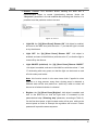
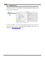
3.2.1.2 SWITCH/SENSOR
Figure 18. Switch/sensor
From the tab that becomes visible after setting a binary input as a switch/sensor (see
Figure 18) it is possible to customise how QUAD should behave regarding the signals
received from the switch/sensor connected to the input port.
http://www.zennio.com
Technical Support: http://zennioenglish.zendesk.com
20
QUAD
The first thing to be set is the input type: “Standard” or “Security (with end of line
resistor)”.
In case of selecting the latter, the “[Ix] Alarm: Breakdown, Sabotage, Unstable line”
1-bit communication object will show up, and will be sent with the value “1” to the KNX
bus, every 30 seconds, whenever QUAD finds the input line to be broken, sabotaged or
unstable (refer to section 2.2 for details). On the contrary, once the failure is over,
QUAD will send the value “0” through that object (only once). Additionally, and only in
case of enabling the security function for the switch/sensor, the following parameters
will show up as well:
Figure 19. Security switch/sensor
Switch/sensor Type: sets how the switch/sensor connected to the QUAD
input port behaves:
N.O. (parallel Resistor): normally open switch/sensor.
N.C. (Serial Resistor): normally closed switch/sensor.
Resistor Value: sets the value in Ohms of the end-of-line resistor being
connected to the switch/sensor. The available values are: 2.2 KΩ; 2.7 KΩ; 3.3
KΩ; 4.7 KΩ; and 10 KΩ.
Further information on how this inputs work can be found in section 2.2.
Both input types (standard and with security) share the following common
parameters:
Rising Edge: sets the action to be performed whenever a rising edge (i.e.,
the circuit gets closed) is detected in the input line. The available options are:
No Action: no action is performed.
0: QUAD will send the value “0” to the KNX bus through the “[Ix] [Sensor]
Edge” 1-bit object.
http://www.zennio.com
Technical Support: http://zennioenglish.zendesk.com
21
QUAD
1: QUAD will send the value “1” to the KNX bus through the “[Ix] [Sensor]
Edge” 1-bit object.
Switching 0/1: QUAD will send the values “1” and “0” alternatively with
every rising edge, that is, a different value each time.
Falling Edge: sets the action to be performed whenever a falling edge (i.e.,
the circuit gets open) is detected in the input line. The available options are
analogous to those already described for the rising edge.
Sending of “0” Delay: sets a certain delay time (in tenths of a second) that
QUAD will wait for after the detection of the edge, prior to sending (through
the “[Ix] [Sensor] Edge” object) the parameterised response in the particular
case of being “0” the value to be sent. Should this response need to be
immediate, this parameter must be set to “0”.
Sending of “1” Delay: sets a certain delay time (in tenths of a second) that
QUAD will wait for after the detection of the edge, prior to sending (through
the “[Ix] [Sensor] Edge” object) the parameterised response in the particular
case of being “1” the value to be sent. Should this response need to be
immediate, this parameter must be set to “0”
Periodical Sending of “0”: sets the cycle time (in seconds) for periodically
sending the value “0” through the “[Ix] [Sensor] Edge” object after the
detection of the corresponding edge in the input line. In case there is no need
to send it cyclically, this field should be left equal to zero.
Periodical Sending of “1”: sets the cycle time (in seconds) for periodically
sending the value “1” through the “[Ix] [Sensor] Edge” object after the
detection of the corresponding edge in the input line. In case there is no need
to send it cyclically, this field should be left equal to zero.
Lock: enables the “[Ix] Lock” 1-bit object, which, on the reception of the
value “1”, locks the input line, so that any event that takes place is ignored
(i.e., edges and alarm situations are not monitored anymore). Once the value
“0” is received, the input is unlocked back. In that moment, depending on the
current state of the line and on the state it had prior to being locked, the edge
and alarm objects may be sent.
http://www.zennio.com
Technical Support: http://zennioenglish.zendesk.com
22
QUAD
Sending Status on Bus Voltage Recovery: when enabled, this function
sends the status objects (including the alarm object, in the case of having the
security function enabled) of the QUAD input (values “0” or “1”, as
corresponding) on the reboot after a bus voltage failure or after an ETS
download / device reset. These objects are actually sent after a configurable
(in seconds) delay.
Note: for safety reasons, if the state of the switch/sensor before the bus
failure differs from the state after the bus recovery, QUAD will send the edge
object to the KNX bus unconditionally, even if this parameter is not set to
“Yes”. Additionally, if QUAD finds an alarm situation (sabotage, breakdown,
etc.) after the bus recovery, it will only send the alarm object to the bus, not
the edge object. Moreover, for safety reasons, if the alarm or no-alarm
situation after the failure differs from the one before the failure, the alarm
object is sent even if the option to send the state during the startup has not
been enabled.
Example:
Let a normally open, security enabled switch/sensor be configured to send the value
“1” on rising edges and the value “0” on falling edges. On bus power recoveries, and as
long as the initial status sending function has been enabled, the edge object will be
sent in any case (provided that there no alarm situations occur). However, whenever
the state of the switch/sensor differs from the one it had before the bus failure, the
status will still be sent to the bus even if the mentioned function has not been enabled.
The examples in the following figure illustrate this behaviour: the dotted lines mark
when the bus failure starts and ends, while the numbers reflect the values being sent to
the bus through the edge object. Similar rules apply to alarm situations and to the initial
sending of the alarm object.
http://www.zennio.com
Technical Support: http://zennioenglish.zendesk.com
23
QUAD
3.2.2 TEMPERATURE PROBE
When an input is set to “temperature probe”, it is possible to configure a set of
parameters from the specific tab that shows up. Apart from that, the “[Ix] Current
temperature” 2-byte object and the “[Ix] Probe error” 1-bit object are shown. The
former will report the current temperature value, as measured by the probe connected
to the input. The second object, on its side, will report whether there is a failure in the
connection of the probe (in such case, the object will acquire the value “1”). As soon as
the connection is re-established, the value of the object will become “0” again.
The default window for the configuration of the temperature probe is shown in Figure
20.
Figure 20. Temperature probe
The following parameters can be configured:
Temperature Sensor Calibration: this option is provided to perform a
permanent correction (between -50 and +50 tenths of a degree) over the
measurements received from the probe, in case the integrator has an
evidence of a deviation between them and the actual temperature of the
room.
Temperature Sending Period: allows selecting a cycle time (from 1 to 100
tens of a second) for periodically sending the currently measured temperature
value to the KNX bus (through the “[Ix] Current Temperature” object). If this
parameter is set to 0, the object will not be periodically.
Send with a Temperature Change: enables an overheating or an
overcooling (or both) protection based on the values received from the
sensor. Depending on the selected protection type, one or two binary
communication objects will show up (“[Ix] Overheating” and “[Ix]
Overcooling”), which will indicate (by acquiring the value “1”) if the
http://www.zennio.com
Technical Support: http://zennioenglish.zendesk.com
24
QUAD
corresponding temperature (upper/lower) limit has been exceeded. It is
therefore necessary to define the overheating and overcooling temperatures
(or both), in Celsius degrees (ºC). Moreover, it is possible to define a
hysteresis (in tenths of a degree) to prevent successively sending the object
when the room temperature keeps moving around the parameterised
temperature limit.
Figure 21. Temperature protection
http://www.zennio.com
Technical Support: http://zennioenglish.zendesk.com
25
QUAD
3.2.3 MOTION DETECTOR
QUAD also provides the option to connect motion detectors to its input ports. In case of
selecting such configuration, up to three virtual detection channels will be available for
each input, that is, up to three virtual detectors may be configured based on the same
measurement so that different parallel responses can be performed on the reception of
the measurements.
Figure 22. Motion detector
After enabling any of the available channels, the following parameter screen will
become available.
Figure 23. Channel configuration
For further information on how the motion sensor works and needs to be configured,
please refer to the “Motion Detector” specific document, available at the
http://www.zennio.com website.
http://www.zennio.com
Technical Support: http://zennioenglish.zendesk.com
26
QUAD
3.3 THERMOSTATS
As advanced in section 2.3, QUAD offers the option to enabling and configuring up to
four thermostats independently.
Figure 24. Configuration of thermostat 1
For further information on how the Zennio thermostat works and needs to be
configured, please refer to the “Zennio Building Thermostat” specific document,
available at the http://www.zennio.com website.
http://www.zennio.com
Technical Support: http://zennioenglish.zendesk.com
27
QUAD
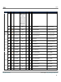
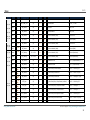
ANNEX I. COMMUNICATION OBJECTS
“Functional range” shows the values that, with independence of any other values permitted by the bus according to the object size, may be of any use or have a particular
meaning because of the specifications or restrictions from both the KNX standard or the application program itself.
“1st boot” shows the cases where an object is assigned a certain value by the application program after a device download or a full reset. In case the value of such assignment
can be parameterised, √ is shown in column “P”. Objects showing a hyphen (-) are not assigned a particular value and therefore can be assumed to be initialised with the value “0”,
or with the corresponding updated value in case they depend on an external element (sensors, etc.). Moreover, if the object is sent (or is there an option to send it) to the bus
(write or read requests) after a download or a device reset from ETS, the marks (W) or (R) will be shown, respectively for transmissions or read requests.
“Reboot” shows the cases where an object is assigned a certain value by the application program after a bus power failure. In case the value of such assignment can be
parameterised, √ is shown in column “P”. Objects showing a hyphen (-) are not assigned a particular value and therefore can be assumed to maintain their previous value after the
failure, or with the corresponding updated value in case they depend on external elements. Moreover, if the object is sent (or is there an option to send it) to the bus (write or read
requests) after a bus failure, the marks (W) or (R) will be shown, respectively for transmissions or read requests.
Number
Size
0, 1, 2, 3
1 Bit
4, 5, 6, 7
1 Bit
8, 9,
10, 11
4 Bit
I/O Flags
C--W
I
CTR
I/O
W-
Data Type (DPT)
Functional Range
DPT_Switch
0/1
0
-
DPT_Bool
0/1
-W
-W
0
-
0x0 (Stop)
0x1 (Dec. by 100%)
0x2 (Dec. by 50%)
0x3 (Dec. by 25%)
0x4 (Dec. by 12%)
0x5 (Dec. by 6%)
0x6 (Dec. by 3%)
CTRO
DPT_Control_Dimming
0x7 (Dec. by 1%)
0x8 (Stop)
0x9 (Inc. by 100%)
0xA (Inc. by 50%)
0xB (Inc. by 25%)
0xC (Inc. by 12%)
0xD (Inc. by 6%)
http://www.zennio.com
1st boot P Reboot P
Name
Function
[Ix] Lock
1=Input Disabled; 0=Enabled
[Ix] Alarm: Breakdown or sabotage
("1"->Active, "0"->No Active)
[Ix] [Short Press] Brighter/Darker
Sh.Pr->Bright/Dark;Sh.Pr->Stop
Technical Support: http://zennioenglish.zendesk.com
28
QUAD
Number
Size
I/O Flags
Data Type (DPT)
Functional Range
1st boot P Reboot P
Name
Function
0xE (Inc. by 3%)
0xF (Inc. by 1%)
4 Bit
4 Bit
12, 13,
14, 15
16, 17,
18, 19
20, 21,
22, 23
CTRDPT_Control_Dimming
CTRO
DPT_Control_Dimming
O
(idem)
0
-
[Ix] [Short Press] Darker
Sh.Pr.->Dark; Sh.Pr.->Stop
(idem)
0
-
[Ix] [Short Press] Brighter
Sh.Pr.->Bright; Sh.Pr.->Stop
1 Byte
O
CTR-
DPT_SceneControl
128-191
0
-
[Ix] [Short Press] Save Scene
Short Pr. -> Send. of 128-191
1 Byte
O
CTR-
DPT_SceneControl
0-63
0
-
[Ix] [Short Press] Run Scene
Short Pr. -> Sending of 0-63
1 Bit
I/O
CTR
W-
DPT_Switch
0/1
0
-
[Ix] [Long Press] Switching
Long Pr. -> Switching "0/1"
1 Bit
I/O
CTR
W-
DPT_Switch
0/1
0
-
[Ix] [Long Press] "1"
Long Pr. -> Sending of "1"
1 Bit
I/O
DPT_Switch
0/1
0
-
[Ix] [Long Press] "0"
Long Pr. -> Sending of "0"
1 Bit
I/O
DPT_Step
0/1
0
-
[Ix] [Long Press] Stop / Step Shutter (switched)
Long Pr. -> Switching "0/1"
1 Bit
I/O
DPT_Step
0/1
0
-
[Ix] [Long Press] Stop / Step Down Shutter
Long Pr. -> Sending of "1"
1 Bit
I/O
DPT_Step
0/1
0
-
[Ix] [Long Press] Stop / Step Up Shutter
Long Pr. -> Sending of "0"
1 Bit
I/O
DPT_UpDown
0/1
0
-
[Ix] [Long Press] Move Up/Down Shutter
Long Pr. -> Switching "0/1"
1 Bit
I/O
CTR
W-
DPT_UpDown
0/1
0
-
[Ix] [Long Press] Move Down Shutter
Long Pr. -> Send. of 1 (Down)
1 Bit
I/O
CTR
W-
DPT_UpDown
0/1
0
-
[Ix] [Long Press] Move Up Shutter
Long Pr. -> Sending of 0 (Up)
1 Bit
I/O
CTR
W-
DPT_Switch
0/1
0
-
[Ix] [Long Press] Dimmer ON/OFF
Long Pr. -> Switching "0/1"
1 Bit
I/O
CTR
W-
DPT_Switch
0/1
0
-
[Ix] [Long Press] Dimmer OFF
Long Pr. -> Send. of 0 (OFF)
1 Bit
I/O
CTR
W-
DPT_Switch
0/1
0
-
[Ix] [Long Press] Dimmer ON
Long Pr. -> Sending of 1 (ON)
0
-
[Ix] [Long Press] Brighter/Darker
Lg.Pr->Bright/Dark; End->Stop
4 Bit
CTR
WCTR
WCTR
WCTR
WCTR
W-
0x0 (Stop)
0x1 (Dec. by 100%)
CTR0x2 (Dec. by 50%)
O
DPT_Control_Dimming
0x3 (Dec. by 25%)
0x4 (Dec. by 12%)
0x5 (Dec. by 6%)
http://www.zennio.com
Technical Support: http://zennioenglish.zendesk.com
29
QUAD
Number
Size
I/O Flags
Data Type (DPT)
Functional Range
1st boot P Reboot P
Name
Function
0x6 (Dec. by 3%)
0x7 (Dec. by 1%)
0x8 (Stop)
0x9 (Inc. by 100%)
0xA (Inc. by 50%)
0xB (Inc. by 25%)
0xC (Inc. by 12%)
0xD (Inc. by 6%)
0xE (Inc. by 3%)
0xF (Inc. by 1%)
24, 25,
26, 27
4 Bit
O
CTRDPT_Control_Dimming
-
(idem)
0
-
[Ix] [Long Press] Darker
Lg.Pr->Dark; End->Stop
4 Bit
O
CTRDPT_Control_Dimming
-
(idem)
0
-
[Ix] [Long Press] Brighter
Lg.Pr->Bright; End->Stop
1 Byte
O
DPT_SceneControl
128-191
0
-
[Ix] [Long Press] Save Scene
Long Pr. -> Send. of 128-191
DPT_SceneControl
0-63
0
-
[Ix] [Long Press] Run Scene
Long Pr. -> Sending of 0-63
DPT_Switch
0/1
0
-
[Ix] Short Circuit
1=Short Circuit;0=No Short Cir
DPT_Switch
0/1
0
-
[Ix] Open Circuit
1=Open Circuit;0=No Open Circ.
DPT_Scaling
0% - 100%
0
-
[Ix] Luminosity level
Luminosity on Input x
1 Byte
28, 29,
30, 31
1 Bit
32, 33,
34, 35
1 Bit
36, 37,
38, 39
1 Byte
CTRCTRO
CT-CT-CTRO
-
1 Bit
I
C--W
-
DPT_Enable
0/1
0
-
[I1][Ch.x] Channel enabling
1=Enable; 0=Disable
1 Bit
I
C--W
-
DPT_Switch
0/1
0
-
[I1][Ch.x] Channel lock
1=Lock; 0=UnLock
1 Bit
I
C--W
-
DPT_Enable
0/1
0
-
[I2][Ch.x] Channel enabling
1=Enable; 0=Disable
1 Bit
I
C--W
-
DPT_Switch
0/1
0
-
[I2][Ch.x] Channel lock
1=Lock; 0=UnLock
1 Bit
I
DPT_Enable
0/1
0
-
[I3][Ch.x] Channel enabling
1=Enable; 0=Disable
1 Bit
I
DPT_Switch
0/1
0
-
[I3][Ch.x] Channel lock
1=Lock; 0=UnLock
1 Bit
I
DPT_Enable
0/1
0
-
[I4][Ch.x] Channel enabling
1=Enable; 0=Disable
1 Bit
I
DPT_Switch
0/1
0
-
[I4][Ch.x] Channel lock
1=Lock; 0=UnLock
DPT_Switch
0/1
0
-
[I1][Ch.x] Detection Status
According to parameters
40, 41, 42
43, 44, 45
46, 47, 48
49, 50, 51
52, 53, 54
1 Bit
http://www.zennio.com
C--W
C--W
C--W
C--W
CT--
Technical Support: http://zennioenglish.zendesk.com
30
QUAD
Number
Size
I/O Flags
Data Type (DPT)
Functional Range
1st boot P Reboot P
Name
Function
55, 56, 57
1 Bit
CT--
DPT_Switch
0/1
0
-
[I2][Ch.x] Detection Status
According to parameters
58, 59, 60
1 Bit
CT--
DPT_Switch
0/1
0
-
[I3][Ch.x] Detection Status
According to parameters
61, 62, 63
1 Bit
CT--
DPT_Switch
0/1
0
-
[I4][Ch.x] Detection Status
According to parameters
64, 65, 66
1 Byte
I
DPT_SceneControl
0-63
0
-
[E1][Canal x] Recepción Escena
0-63 (Ejec. Escena 1-64)
67, 68, 69
1 Byte
I
DPT_SceneControl
0-63
0
-
[I1][Ch.x] Scene Reception
0-63 (Run Scene 1-64)
70, 71, 72
1 Byte
I
DPT_SceneControl
0-63
0
-
[I2][Ch.x] Scene Reception
0-63 (Run Scene 1-64)
73, 74, 75
1 Byte
I
DPT_SceneControl
0-63
0
-
[I3][Ch.x] Scene Reception
0-63 (Run Scene 1-64)
76, 77, 78
1 Byte
DPT_SceneControl
0-63
0
-
[I4][Ch.x] Scene Reception
0-63 (Run Scene 1-64)
79, 80, 81
1 Byte
CT--
DPT_SceneControl
0-63
0
-
[I1][Ch.x] Scene Sending
0-63 (Send Scene 1-64)
82, 83, 84
1 Byte
CT--
DPT_SceneControl
0-63
0
-
[I2][Ch.x] Scene Sending
0-63 (Send Scene 1-64)
85, 86, 87
1 Byte
CT--
DPT_SceneControl
0-63
0
-
[I3][Ch.x] Scene Sending
0-63 (Send Scene 1-64)
88, 89,
90, 91
2 Bytes
O
CTR-
DPT_Value_Temp
-273.00 - 670760.00
25,00
-
[Ix] Current Temperature
Temperature sensor value
92, 93,
94, 95
1 Bit
O
DPT_Switch
0/1
0
-
[Ix] Overcooling
1=Overcooling;0=No Overcooling
96, 97,
98, 99
1 Bit
DPT_Switch
0/1
0
-
[Ix] Overheating
1=Overheating;0=No Overheating
100, 101,
102, 103
1 Bit
DPT_Switch
0/1
0
-
[Ix] Probe Error
1=Error;0=No Error
104, 106,
108, 110
2 Bytes
DPT_Value_Temp
-273.00 - 670760.00
25,00
-
[Tx] Temperature Source 1
External Sensor Measure
105, 107,
109, 111
2 Bytes
DPT_Value_Temp
-273.00 - 670760.00
25,00
-
[Tx] Temperature Source 2
External Sensor Measure
112, 113,
114, 115
1 Byte
I
C--W
-
DPT_HVACMode
0=Comfort;
1=Standby;
3=Economy
0
-
[Tx] Special Mode
1-byte HVAC Mode
116, 120,
124, 128
1 Bit
I
C--W
-
DPT_Trigger
0/1
1
-
[Tx] Special Mode: comfort
0=Nothing; 1=Trigger
C--W
C--W
C--W
C--W
CT--
CTRCTRO
CTRO
C--W
I
C--W
I
-
http://www.zennio.com
Technical Support: http://zennioenglish.zendesk.com
31
QUAD
Number
Size
I/O Flags
C--W
C--W
C--W
-
Data Type (DPT)
Functional Range
1st boot P Reboot P
Name
Function
DPT_Switch
0/1
0
-
[Tx] Special Mode: comfort
0=Off; 1=On
DPT_Trigger
0/1
0
-
[Tx] Special Mode: standby
0=Nothing; 1=Trigger
DPT_Switch
0/1
0
-
[Tx] Special Mode: standby
0=Off; 1=On
1 Bit
I
1 Bit
I
1 Bit
I
1 Bit
I
C--W
-
DPT_Trigger
0/1
0
-
[Tx] Special Mode: economy
0=Nothing; 1=Trigger
1 Bit
I
C--W
-
DPT_Switch
0/1
0
-
[Tx] Special Mode: economy
0=Off; 1=On
1 Bit
I
C--W
-
DPT_Trigger
0/1
0
-
[Tx] Special Mode: protection
0=Nothing; 1=Trigger
1 Bit
I
C--W
-
DPT_Switch
0/1
0
-
[Tx] Special Mode: protection
0=Off; 1=On
132, 133,
134, 135
1 Bit
I
DPT_Window_Door
0/1
0
-
[Tx] Window Status (input)
0=Closed; 1=Open
136, 137,
138, 139
1 Bit
I
DPT_Trigger
0/1
0
-
[Tx] Comfort Prolongation
0=Nothing; 1=Timed Comfort
140, 141,
142, 143
1 Byte
O
DPT_HVACMode
0=Comfort;
1=Standby;
3=Economy
0W
[Tx] Special Mode Status
1-byte HVAC Mode
2 Bytes
I
DPT_Value_Temp
-273.00 - 670760.00
0
-
[Tx] Setpoint
Thermostat setpoint input
2 Bytes
I
DPT_Value_Temp
-273.00 - 670760.00
0
-
[Tx] Basic Setpoint
Reference setpoint
148, 149,
150, 151
1 Bit
I
DPT_Step
0/1
0
-
[Tx] Setpoint Step
0=-0.5ºC; 1=+0.5ºC
152, 153,
154, 155
2 Bytes
I
DPT_Value_Tempd
-10.00 – 10.00
0
-
[Tx] Setpoint Offset
Float offset value
156, 157,
158, 159
2 Bytes
O
CTR-
DPT_Value_Temp
-273.00 - 670760.00
-W
√ -W
[Tx] Setpoint Status
Current setpoint
160, 161,
162, 163
2 Bytes
O
CTR-
DPT_Value_Temp
-273.00 - 670760.00
-W
√ -W
[Tx] Basic Setpoint Status
Current basic setpoint
164, 165,
166, 167
2 Bytes
O
CTR-
DPT_Value_Tempd
-10.00 – 10.00
0W
-W
[Tx] Setpoint Offset Status
Current setpoint offset
1 Bit
I
C--W
-
DPT_Reset
0/1
0
-
[Tx] Setpoint Reset
Reset setpoint to default
1 Bit
I
C--W
-
DPT_Reset
0/1
0
-
[Tx] Offset Reset
Reset offset
1 Bit
I
C--W
DPT_Heat_Cool
0/1
0
-
[Tx] Mode
0 = Cool; 1 = Heat
117, 121,
125, 129
118, 122,
126, 130
119, 123,
127, 131
144, 145,
146, 147
168, 169,
170, 171
172, 173,
http://www.zennio.com
C--W
C--W
CTRC-C-C-C--
W
W
W
W
√ -W
Technical Support: http://zennioenglish.zendesk.com
32
QUAD
Number
Size
I/O Flags
Data Type (DPT)
Functional Range
1st boot P Reboot P
Name
Function
-
174, 175
176, 177,
178, 179
1 Bit
O
CTR-
DPT_Heat_Cool
0/1
-W
180, 181,
182, 183
1 Bit
I
C--W
-
DPT_Switch
0/1
0
184, 185,
186, 187
1 Bit
O
CTR-
DPT_Switch
0/1
-W
√ -W
1 Bit
O
DPT_Switch
0/1
-W
-W
[Tx] Control Variable (Cool)
2-Point Control
1 Bit
O
DPT_Switch
0/1
-W
-W
[Tx] Control Variable (Cool)
PI Control (PWM)
1 Bit
O
DPT_Switch
0/1
-W
-W
[Tx] Control Variable (Heat)
2-Point Control
1 Bit
O
DPT_Switch
0/1
-W
-W
[Tx] Control Variable (Heat)
PI Control (PWM)
196, 198,
200, 202
1 Byte
O
DPT_Scaling
0% - 100%
-W
-W
[Tx] Control Variable (Cool)
PI Control (Continuous)
197, 199,
201, 203
1 Byte
O
CTR-
DPT_Scaling
0% - 100%
-W
-W
[Tx] Control Variable (Heat)
PI Control (Continuous)
204, 206,
208, 210
1 Bit
O
CTR-
DPT_Switch
0/1
-W
-W
[Tx] Additional Cool
Temp >= (Setpoint+Band) => "1"
205, 207,
209, 211
1 Bit
O
CTR-
DPT_Switch
0/1
-W
-W
[Tx] Additional Heat
Temp <= (Setpoint-Band) => "1"
1 Bit
I/O
CTR
W-
DPT_Switch
0/1
0
-
[I1] [Short Press] Dimmer ON/OFF
Short Pr. -> Switching "0/1"
1 Bit
I/O
DPT_Switch
0/1
0
-
[I1] [Short Press] Dimmer OFF
Short Pr. -> Send. of 0 (OFF)
1 Bit
I/O
DPT_Switch
0/1
0
-
[I1] [Short Press] Dimmer ON
Short Pr. -> Sending of 1 (ON)
1 Bit
I/O
DPT_Step
0/1
0
-
[I1] [Short Press] Stop / Step Shutter (switched)
Short Pr. -> Switching "0/1"
1 Bit
I/O
DPT_Step
0/1
0
-
[I1] [Short Press] Stop / Step Down Shutter
Short Pr. -> Sending of "1"
1 Bit
I/O
DPT_Step
0/1
0
-
[I1] [Short Press] Stop / Step Up Shutter
Short Pr. -> Sending of "0"
1 Bit
I/O
CTR
W-
DPT_UpDown
0/1
0
-
[I1] [Short Press] Move Up/Down Shutter
Short Pr. -> Switching "0/1"
1 Bit
I/O
CTR
W-
DPT_UpDown
0/1
0
-
[I1] [Short Press] Move Down Shutter
Short Pr. -> Send. of 1 (Down)
1 Bit
I/O C T R
DPT_UpDown
0/1
0
-
[I1] [Short Press] Move Up Shutter
Short Pr. -> Sending of 0 (Up)
188, 190,
192, 194
189, 191,
193, 195
212, 213,
214, 215
http://www.zennio.com
CTR
CTR
CTR
CTR
CTR
-
-
CTR
WCTR
WCTR
WCTR
WCTR
W-
√ -W
-
[Tx] Mode Status
0 = Cool; 1 = Heat
[Tx] On/Off
0=Off; 1=On
√ [Tx] On/Off Status
0=Off; 1=On
Technical Support: http://zennioenglish.zendesk.com
33
QUAD
Number
Size
I/O Flags
Data Type (DPT)
Functional Range
1st boot P Reboot P
Name
Function
W1 Bit
I/O
CTR
W-
DPT_Switch
0/1
0
-
[I1] [Short Press] Switching
Short Pr. -> Switching "0/1"
1 Bit
I/O
CTR
W-
DPT_Switch
0/1
0
-
[I1] [Short Press] "1"
Short Pr. -> Sending of "1"
1 Bit
I/O
CTR
W-
DPT_Switch
0/1
0
-
[I1] [Short Press] "0"
Short Pr. -> Sending of "0"
1 Bit
I/O
CTR
W-
DPT_Switch
0/1
-W
http://www.zennio.com
√ -W
√ [I1] [Sensor] Edge
Edge -> Sending of "0" or "1"
Technical Support: http://zennioenglish.zendesk.com
34
Join and send us your inquiries
about Zennio devices:
http://zennioenglish.zendesk.com
Zennio Avance y Tecnología S.L.
C/ Río Jarama, 132. Nave P-8.11
45007 Toledo (Spain).
Tel. +34 925 232 002.
Fax. +34 925 337 310.
www.zennio.com
[email protected]