1
User Manual for the
HE800DNT450
DeviceNet Master
(Scanner)
First Edition
19 April 2002
SUP0462-01
SUP0462-01
19 APR 2002
PAGE 3
PREFACE
This manual explains how to use the Horner APG’s DeviceNet Master (Scanner).
Copyright (C) 2002 Horner APG, LLC., 640 North Sherman Drive, Indianapolis, Indiana 46201.
All rights reserved. No part of this publication may be reproduced, transmitted, transcribed,
stored in a retrieval system, or translated into any language or computer language, in any form
by any means, electronic, mechanical, magnetic, optical, chemical, manual or otherwise, without
the prior agreement and written permission of Horner APG, LLC.
All software described in this document or media is also copyrighted material subject to the
terms and conditions of the Horner Software License Agreement.
Information in this document is subject to change without notice and does not represent a
commitment on the part of Horner APG, LLC.
DeviceNet is a trademark of Open DeviceNet Vendors Association (ODVA).
Windows and Windows-95 are trademarks of Microsoft Corporation
SmartStack, Cscape, and CsCAN are trademarks of Horner APG, LLC.
For user manual updates, contact Horner APG, Technical
Support Division, at (317) 916-4274 or visit our website at
www.heapg.com.
PAGE 4
19 APR 2002
SUP0462-01
LIMITED WARRANTY AND LIMITATION OF LIABILITY
Horner APG, LLC. ("HE") warrants to the original purchaser that the DeviceNet Master (Scanner)
manufactured by HE is free from defects in material and workmanship under normal use and
service. The obligation of HE under this warranty shall be limited to the repair or exchange of
any part or parts which may prove defective under normal use and service within two (2) years
from the date of manufacture or eighteen (18) months from the date of installation by the original
purchaser whichever occurs first, such defect to be disclosed to the satisfaction of HE after
examination by HE of the allegedly defective part or parts. THIS WARRANTY IS EXPRESSLY
IN LIEU OF ALL OTHER WARRANTIES EXPRESSED OR IMPLIED INCLUDING THE
WARRANTIES OF MERCHANTABILITY AND FITNESS FOR USE AND OF ALL OTHER
OBLIGATIONS OR LIABILITIES AND HE NEITHER ASSUMES, NOR AUTHORIZES ANY
OTHER PERSON TO ASSUME FOR HE, ANY OTHER LIABILITY IN CONNECTION WITH
THE SALE OF THIS DEVICENET MASTER (SCANNER). THIS WARRANTY SHALL NOT
APPLY TO THIS DEVICENET MASTER (SCANNER) OR ANY PART THEREOF WHICH HAS
BEEN SUBJECT TO ACCIDENT, NEGLIGENCE, ALTERATION, ABUSE, OR MISUSE. HE
MAKES NO WARRANTY WHATSOEVER IN RESPECT TO ACCESSORIES OR PARTS NOT
SUPPLIED BY HE. THE TERM "ORIGINAL PURCHASER", AS USED IN THIS WARRANTY,
SHALL BE DEEMED TO MEAN THAT PERSON FOR WHOM THE DEVICENET MASTER
(SCANNER) IS ORIGINALLY INSTALLED. THIS WARRANTY SHALL APPLY ONLY WITHIN
THE BOUNDARIES OF THE CONTINENTAL UNITED STATES.
In no event, whether as a result of breach of contract, warranty, tort (including negligence) or
otherwise, shall HE or its suppliers be liable of any special, consequential, incidental or penal
damages including, but not limited to, loss of profit or revenues, loss of use of the products or
any associated equipment, damage to associated equipment, cost of capital, cost of substitute
products, facilities, services or replacement power, down time costs, or claims of original
purchaser's customers for such damages.
To obtain warranty service, return the product to your distributor with a description of the
problem, proof of purchase, post paid, insured and in a suitable package.
ABOUT PROGRAMMING EXAMPLES
Any example programs and program segments in this manual or provided on accompanying
diskettes are included solely for illustrative purposes. Due to the many variables and
requirements associated with any particular installation, Horner APG cannot assume
responsibility or liability for actual use based on the examples and diagrams. It is the sole
responsibility of the system designer utilizing the DeviceNet Master (Scanner) to appropriately
design the end system, to appropriately integrate the DeviceNet Master (Scanner) and to make
safety provisions for the end equipment as is usual and customary in industrial applications as
defined in any codes or standards which apply. It assumed that the system designer is familiar
with PLC programming and configuration.
Note: The programming examples shown in this manual are for illustrative
purposes only. Proper machine operation is the sole responsibility of the
system integrator.
SUP0462-01
19 APR 2002
PAGE 5
TABLE OF CONTENTS
PREFACE .................................................................................................................................3
LIMITED WARRANTY AND LIMITATION OF LIABILITY...........................................................4
ABOUT PROGRAMMING EXAMPLES......................................................................................4
TABLE OF CONTENTS.............................................................................................................5
CHAPTER 1: INTRODUCTION ................................................................................................7
1.1
Overview .....................................................................................................................7
1.2
DNT450 Features ........................................................................................................7
1.3
Technical Specifications ..............................................................................................8
CHAPTER 2: INSTALLATION ..................................................................................................9
2.1
Installing and Removing a SmartStack Module (Shown with the OCS) ........................9
2.2
Connectors ................................................................................................................10
2.2.1
DeviceNet I/O Connector (CAN A) ......................................................................10
2.3
LED Indicators ...........................................................................................................11
CHAPTER 3: DEVICENET NODE, DNT450 & PLC RELATIONSHIPS ...................................13
3.1
General .....................................................................................................................13
3.2
Module to PLC Register Mapping...............................................................................13
3.3
Node to PLC Register Mapping..................................................................................13
3.4
Message Packets and Fragmentation ........................................................................13
3.5
Physical Limitations ...................................................................................................13
3.6
Data Assemblies........................................................................................................14
3.7
DNT450 Configuration Introduction............................................................................15
3.8
DeviceNet Node Priority and Implications ..................................................................17
3.9
Fault Table ................................................................................................................17
CHAPTER 4: DNT450 REGISTER REQUIREMENTS ............................................................21
CHAPTER 5: EXPLICIT MESSAGING USING DNT450 .........................................................25
5.1
General .....................................................................................................................25
5.2
Building Explicit Messages ........................................................................................25
5.3
How to Interpret Explicit Response Messages............................................................26
5.4
Explicit Message Errors .............................................................................................27
CHAPTER 6: CONFIGURATION............................................................................................29
6.1
General .....................................................................................................................29
6.2
Configuration .............................................................................................................29
6.2.1
Select the Module to be Configured ....................................................................29
6.2.2
Configure the Module..........................................................................................30
6.2.3
Creating the network configuration......................................................................32
CHAPTER 7: DEVELOPING USER SOFTWARE...................................................................35
7.1
Software Support for the Polled Connection...............................................................35
APPENDIX A: DNT450 NETWORK OPERATION ..................................................................37
A.1 Sequence of Events...................................................................................................37
A.2 Establishing a Connection..........................................................................................37
A.3 Send a Polled Message .............................................................................................37
A.4 Explicit NOPs ............................................................................................................37
APPENDIX B: DEVICENET TIMING.......................................................................................39
B.1 Message Packet Timing.............................................................................................39
B.2 Network Scan Time versus PLC Scan Time...............................................................39
APPENDIX C: DEVICENET ERROR CODES.........................................................................41
INDEX .....................................................................................................................................43
PAGE 6
19 APR 2002
SUP0462-01
SUP0462-01
19 APR 2002
PAGE 7
CH.1
CHAPTER 1: INTRODUCTION
1.1
Overview
The DeviceNet Scanner (HE800DNT450) is an intelligent communications interface module. The
DNT450 allows an Operator Control Station (OCS) to supervise a DeviceNet network.
Up to 63 slave devices can be connected via DeviceNet to the DNT450. Depending on baud rate and the
cable type used, the DeviceNet slave nodes can be located up to 1,500 feet (457.2 meters) from the
PLC.
DNT450 Polled data is mapped directly into the PLC's %I, %Q, %AI and %AQ registers. The ladder
programmer can treat the DNT450 and its attached DeviceNet nodes as a large I/O module. Polled data
is transferred between the PLCs registers and the DeviceNet slave nodes without any user or ladder
code intervention.
The DeviceNet specification provides two methods of establishing communications between a scanner
and its nodes. The first method makes use of the “Unconnected Message Manager” (UCMM) and the
second is known as “Group 2 Only”. “Group 2 Only” is the simplest. Because of its simplicity, many slave
devices only support the “Group 2 Only” method. The DNT450 allows both of these methods to be used
simultaneously. Any single DeviceNet slave device can be either a Group 2 Only node or a UCMM node,
never both. A DeviceNet network can be made up of a mixture of “Group 2 Only” and UCMM” slave
devices.
1.2
DNT450 Features
The DNT450 supports the following DeviceNet features:
• Baud Rates: 125K, 250K, and 500K,
• UCMM protocol (Log on),
• Group 2 Only protocol,
• The Polled Connection,
• Ladder Initiated Explicit Messaging (LIEM),
• Fragmentation on both polled and explicit connections,
• All four Message Body Formats under UCMM.
When using Polled Messaging, data is read from the PLC’s %Q and %AQ registers by the DNT450,
formatted into DeviceNet packets and sent to the DeviceNet nodes. As data produced by the DeviceNet
nodes is received by the DNT450, it is converted into PLC register notation and stored in the PLC's %I
and %AI registers. This happens automatically without the need for block move or other ladder program
intervention.
PAGE 8
CH. 1
1.3
19 APR 2002
SUP0462-01
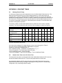
Technical Specifications
Table 1.1 - DNT450 Specifications
DeviceNet Network Specifications
Parameter
Minimum
Maximum
Units
DeviceNet Power Voltage
11
25
V
DeviceNet Power Load
65
mA
DeviceNet Signal Baud Rate
125
500
KHz
DeviceNet Signal Driver Fanout
0
63
Devices
PLC Power Load Specifications
Parameter
Minimum
Maximum
Units
+5Vdc (LOGIC)
0
175
mA
+24Vdc (RELAY)
0
0
mA
+24Vdc (ISOLATED)
0
0
mA
Environmental Specifications
Parameter
Minimum
Maximum
Units
Operating Temperature
0
+60
Deg C
Storage Temperature
-40
+85
Deg C
Humidity (non-condensing)
5
95
% RH
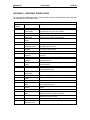
Cable Specifications
Description
Belden #
DeviceNet "Thick" Cable
3082A
One twisted pair for signal,18 gauge, separately foil shielded.
One twisted pair for power, 15 gauge, separately foil shielded.
Overall foil/braid shield with 18 gauge drain.
8 Amps maximum power.
Description
Belden #
DeviceNet "Thin" Cable
3084A
One twisted pair for signal, 24 gauge, separately foil shielded.
One twisted pair for power, 22 gauge, separately foil shielded.
Overall foil/braid shield with 22 gauge drain.
3 amps maximum power.
DeviceNet Cable Length vs Network Baud Rate
Maximum Cable Distance
DeviceNet Baud Rate
Thick Cable
Thin Cable
125KHz
1640 Feet
328 Feet
250KHz
820 Feet
328 Feet
500kHz
328 Feet
328 Feet
Maximum Drop Distance
DeviceNet Baud Rate
Per Drop
Cumulative
125KHz
20 Feet
512 Feet
250KHz
20 Feet
256 Feet
500kHz
20 Feet
128 Feet
These specifications are subject to change without notice.
Required Power
(Steady State)
Required Power (Inrush)
Relative Humidity
General Specifications
Operating
To be Determined
Temperature
To be Determined
Terminal Type
5 to 95% Non-condensing Weight
0° to 60° Celsius
Spring Clamp, Removable
9.5 oz. (270 g)
These specifications are subject to change without notice.
See ODVA DeviceNet Specification, Volume 1, Section 9.3 for complete DeviceNet cabling
specifications.
SUP0462-01
19 APR 2002
PAGE 9
CH. 2
CHAPTER 2: INSTALLATION
2.1
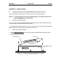
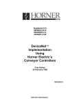
Installing and Removing a SmartStack Module (Shown with the OCS)
The following section describes how to install and remove a SmartStack Module.
Caution: To function properly and avoid possible damage, do not install more than four
Smart Stack Modules per OCS or RCS.
a.
Installing SmartStack Modules
1. Hook the tabs. Each SmartStack Module has two tabs that fit into slots located on the OCS.
(The slots on the OCS are located on the back cover.)
2. Press the SmartStack Module into the “locked” position, making sure to align the SmartStack
Module fasteners with the SmartStack receptacles on the OCS.
b.
Removing SmartStack Modules
1. Using a flathead screwdriver, pry up the end of the SmartStack Module (opposite of tabs)
and swing the module out.
2. Lift out the tabs of the module.
SmartStack Tab
Fastener
Mating Pins
OCS Back Cover
Figure 2.1 – Installing a SmartStack Module in an OCS
PAGE 10
CH. 2
19 APR 2002
2.2
Connectors
2.2.1
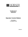
DeviceNet I/O Connector (CAN A)
SUP0462-01
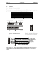
The DeviceNet I/O connector (CAN A) is located next to the RS-232 serial port. It consists of a 5pin removable screw terminal with the following terminal descriptions:
Pin
1
2
3
4
5
DeviceNet Port (CAN)
V-
N/A
L SH H V+
CAN A
R X + R X - TX + TX - C
RS485
N/A
Table 2.2 – DeviceNet I/O Connector Pinout
Signal
Description
VPower CAN_L
Signal Drain
Shield
CAN_H
Signal +
V+
Power +
RS232
V-
Factory Reserved
M A IN T E N A N C E
5
4
3
2
1
L SH H V+
CAN B
001DNT002
N/A
Figure 2.2 – DNT450 Connectors
Figure 2.3 - DeviceNet I/O Connector
(As Viewed from Front of Module)
DNT450
5
4
3
2
1
CAN_L (BLUE)
CAN_H (WHITE)
SHIELD
V+ (RED)
V- (BLACK)
Figure 2.4 - DeviceNet Wiring
A user-supplied 121Ω ¼W 1% resistor is needed for termination at EACH END of the network
cabling. Refer to the DeviceNet cabling specifications for proper location of the terminating
resistor.
SUP0462-01
2.3
19 APR 2002
PAGE 11
CH. 2
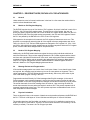
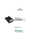
LED Indicators
The DNT450 provides two bi-color (Red/Green) diagnostic LEDs on its front panel. These LEDs
are located on the same side of the module as the Devicenet port, and the RS232 port. The
network status LED is nearest to the edge of the module.
NSB
N/A
RS485
TX RX
N/A
RS232
TX RX
RS-232 Port TX / RX LEDs
MS
NSA
Module Status
Network Status for DNT450
001DNT001
Figure 2.5 – LEDs
For this state
No Power
Device
Operational
Device in Standby
Minor Fault
Unrecoverable
Fault
Device Self
Testing
For this state
Not powered or
Not On–line
Module On–line
and
Connected.
Network OK
Module On–line
but
Not connected
Connection
Time–Out
Critical Link
Failure
Device Self Test
Device in Standby
Table 2.3 - Module Status LED (MS)
Module Status LED is Condition
Off
There is no power applied to the module.
Green
The module is operating normally.
Flashing Green
Flashing Red
Red
The module has no configuration.
Recoverable Fault
The module has an unrecoverable fault.
Flashing
Red-Green
The module is in Self Test.
Table 2.4 - Network Status LED (NSA)
Network Status LED is Condition
The module may not be powered.
Module is not on–line.
Off
Module has not completed Dup_MAC_ID
test.
Green
The module is on-line and has all
connections in the established state.
Flashing Green
Module has passed the Dup_MAC_ID test
and is on-line but has not established a
connection with one or more nodes.
Flashing Red
One or more Connections have Timed–Out.
Red
Failed communication device.
Flashing
Red-Green
Flashing Red
Device is in self test
The module has no configuration
PAGE 12
CH. 2
19 APR 2002
NOTES
SUP0462-01
SUP0462-01
19 APR 2002
PAGE 13
CH. 3
CHAPTER 3: DEVICENET NODE, DNT450 & PLC RELATIONSHIPS
3.1
General
Unless otherwise noted, all numeric radixes are in decimal. In a few cases the notation 0xhh is
used to indicate Hexadecimal radix.
3.2
Module to PLC Register Mapping
The DNT450 requires the use of four blocks of PLC registers. One block is defined in each of the
PLCs %I, %AI, %Q and %AQ register space. Through the use of the Cscape, the user can
specify the starting register and the size of each of these four register blocks. Data from the PLC
to the DNT450 (and to the DeviceNet nodes) are passed in the %Q and %AQ registers. Data to
the PLC are passed by the DNT450 in the PLCs %I and %AI registers.
With respect to the examples in this manual, the PLC register references are set to one. This
simplifies our examples by assuming that all of the register reference assignments start at one.
That is, the first %I, %Q, %AI and %AQ registers are assigned to PLC register %I1, %Q1, %AI1
and %AQ1. Although these register assignments can be placed anywhere within the PLC register
space, we have made these assignments for simplicities sake.
3.3
Node to PLC Register Mapping
Additionally, the DNT450 subdivides these register blocks providing individual sub-blocks to
each DeviceNet node. This provides mapping between the PLC’s data registers and the data to
and from each individual DeviceNet node. As a result, each node’s polled data is immediately
available to the PLC ladder code by accessing the appropriate PLC register(s). Note that the
node to PLC register assignments must be contained within the Module register definitions
defined in Module to PLC Register Mapping discussed above.
3.4
Message Packets and Fragmentation
A DeviceNet message packet can contain from 0 to 8 bytes of data. If more than 8 bytes of data
are required, the message must be broken up into two or more packets or fragments. This is
called fragmentation. The DNT450 handles this automatically, without any intervention by the
user or the ladder program running in the PLC.
Fragmentation works differently for Polled messages than Explicit messages. In the case of
Polled messages, each message fragment is sent to the receiving party one after the other as
fast as possible. In the case of large Explicit messages, the sender will send only the first packet.
The sender then waits for an ACK message from the receiver. Upon receiving the ACK, the
sender then transmits the next packet and waits for another ACK. This process repeats until all
message fragments have been sent. This ACK process requires a considerable amount of time
when compared to Polled messages.
3.5
Physical Limitations
There are physical limits on the amount of data that can be transferred between the DNT450 and
the PLC. This limit is 300 bytes of %I and %AI data and 300 bytes of %Q and %AQ data.
The smallest data item that DeviceNet can handle is one byte. If an application requires only a
single %Q output or command bit, a group of 8 %Qs must be allocated. The remaining 7 will be
unused (or wasted). The same is true for bit type input data.
PAGE 14
CH. 3
3.6
19 APR 2002
SUP0462-01
Data Assemblies
For a Polled Connection, the data bytes within the DeviceNet messages must be sent and
received in a predetermined order. This order is specified by “Data Assemblies”. Data
Assemblies are published by the manufacturer of the DeviceNet node. To properly map the
DeviceNet data to or from the PLC, the data assemblies for each DeviceNet node must be
available and understood. Consult data sheets from the DeviceNet node manufacturer for
specific details on Data Assemblies.
From the point of view of the PLC, all input is via %I and %AI registers and all output data is via
%Q and %AQ registers. From the point of view of the DeviceNet nodes, all I/O is via streams of
data bytes, known as Data Assemblies, that they send and receive. In most DeviceNet nodes,
the data assembly formats are fixed, in others they are configurable. Consult data sheets from
the DeviceNet node manufacturer for details on Data Assemblies.
The DNT450 accepts output data from the PLC in the form of %Q and/or %AQ registers. It then
translates this data into DeviceNet polled messages, and sends them to the node. The DNT450
receives DeviceNet polled response messages from the addressed DeviceNet node, translates
these DeviceNet messages and passes the data on to the PLC where they are stored in the
appropriate %I and/or %AI registers.
The DNT450 allows up to 4 blocks of data to be concatenated to form a data assembly. Each
block can be configured as either bit data or word data. The number of bits or words within each
block is also configurable. Keep in mind that bits must be assigned in groups of 8 bits. The user
can configure, for example, that the first block will contain 32 bits, the second block might
contain 7 words, the third block might contain 8 bits and the forth block might contain 5 words.
This would result in a data assembly that contains: 32 bits followed by 7 words followed by 8 bits
followed by 5 words. This example results in a data assembly that contains 29 bytes. The user
must define a data assembly for both the input and output data for each node on the network.
SUP0462-01
3.7
19 APR 2002
PAGE 15
CH. 3
DNT450 Configuration Introduction
Configuration of the DNT450 is performed using a PC running Cscape Software. There are a
number of steps required in order to properly configure the DNT450 DeviceNet scanner module.
These steps include:
Add the DNT450 to the OCS SmartStack I/O Configuration.
Specify the DNT450’s MACID.
Specify the network baud rate.
Specify the module’s first %I register number.
Specify the module’s first %Q register number.
Specify the module’s first %AI register number.
Specify the module’s first %AQ register number.
For each configured node,
Specify the node’s first %I register number.
Specify the node’s first %Q register number.
Specify the node’s first %AI register number.
Specify the node’s first %AQ register number.
Specify the node’s Polled Expected Packet Rate.
Specify the node’s Minimum Polled Scan Time.
Specify the node’s Maximum Polled Response Time.
Specify the node’s Maximum Explicit Response Time.
Specify the node’s Input Data Assembly.
Specify the node’s Output Data Assembly.
Specify the node’s Polled Delay Time.
Each of these items are briefly discussed below:
Add the DNT450 to the OCS SmartStack I/O. Refer to Chapter Six for configuration details.
Specify the DNT450’s MACID.
This is the network address that the DNT450 will respond to. All nodes on the network,
including the DNT450 must be configured with a unique MACID.
Specify the network baud rate.
This is the data bit rate at which all nodes on the network will operate. All nodes on the
network must be configured to operate with the same baud rate.
Specify the module’s first %I register number.
This entry specifies the first register in the block of PLC %I registers that is assigned to
the DNT450 module.
Specify the module’s first %Q register number.
This entry specifies the first register in the block of PLC %Q registers that is assigned to
the DNT450 module.
Specify the module’s first %AI register number.
This entry specifies the first register in the block of PLC %AI registers that is assigned to
the DNT450 module.
Specify the module’s first %AQ register number.
This entry specifies the first register in the block of PLC %AQ registers that is assigned
to the DNT450 module.
PAGE 16
CH. 3
19 APR 2002
SUP0462-01
Scan List.
Before the DNT450 can communicate with any DeviceNet nodes, it must be configured
with a Scan List. The Scan List specifies which DeviceNet nodes to query. Only those
nodes specified in the Scan List are considered to exist on the network. The DNT450
needs additional information about each of the nodes in the Scan List. For each node
included in the Scan List:
Specify the node’s first %I register number.
This entry specifies the first register in the block of PLC %I registers that
are assigned to this node. Note that this block must be part of the larger
block of %I registers assigned to the DNT450 above.
Specify the node’s first %Q register number.
This entry specifies the first register in the block of PLC %Q registers
that are assigned to this node. Note that this block must be part of the
larger block of %Q registers assigned to the DNT450 above.
Specify the node’s first %AI register number.
This entry specifies the first register in the block of PLC %AI registers
that are assigned to this node. Note that this block must be part of the
larger block of %AI registers assigned to the DNT450 above.
Specify the node’s first %AQ register number.
This entry specifies the first register in the block of PLC %AQ registers
that are assigned to this node. Note that this block must be part of the
larger block of %AQ registers assigned to the DNT450 above.
Specify the node’s Polled Expected Packet Rate.
This entry specifies the Expected Packet Rate that will be loaded into
the node when a dialogue is established with the node. The node uses
this number multiplied by four as an inactivity timer limit value. The
node resets the inactivity timer each time it receives a polled request
message from the DNT450. If the timer expires the node will enter the
timed-out state, effectively taking itself off-line.
Specify the node’s Minimum Polled Scan Time.
This is the minimum amount of time that the DNT450 will wait between
sending polled requests to the node. In effect, this is the minimum time
between consecutive scans to the node. Once the system is running, the
actual polled scan time can be displayed through the fault table facility in
real time.
Specify the node’s Maximum Polled Response Time.
This is the maximum time that the DNT450 will wait for a polled
response from the node. If this timer expires, the node is taken off-line.
Then at the next opportunity, the DNT450 will attempt to reconnect to
the node.
Specify the node’s Maximum Explicit Response Time.
This is the maximum time that the DNT450 will wait for an explicit
response from the node. If this timer expires, the node is taken off-line.
Then at the next opportunity, the DNT450 will attempt to reconnect to
the node.
SUP0462-01
19 APR 2002
PAGE 17
CH. 3
Specify the node’s Input Data Assembly.
This item specifies the input data assembly for data received from the
node. See section 3.6 for more details.
Specify the node’s Output Data Assembly.
This item specifies the output data assembly for data being sent to the
node. See section 3.6 for more details.
Specify the node’s Polled Delay Time.
Some older slave nodes can not accept fragmented polled data packets
sent at full speed, especially if the baud rate is 500KB. This entry
instructs the DNT450 to insert a delay between polled fragmented
packets addressed to this node. For most nodes, this entry should be set
to zero. If required, try a value of 100 or 200.
3.8
DeviceNet Node Priority and Implications
The DNT450 can carry on conversations with several DeviceNet nodes simultaneously. Because
of this, DeviceNet Node Priorities become important. Within the scheme of CAN
communications, there is a concept known as Arbitration. If two slaves begin to transmit CAN
messages simultaneously, the slave with the smallest node address will win. The loser must
immediately stop transmitting and try again later. This gives obvious priority to the slave with the
lower node address. This can create problems if care is not taken in the assignment of node
addresses.
Consideration should be given to the priorities of the individual nodes. In the design of most
networks, there are usually a few nodes that require a higher priority than the rest. These nodes
should be assigned the lower node addresses.
3.9
Fault Table
The DNT450 provides a fault table that makes available the status of each node on the network.
PLC registers %Q3, %Q4, %Q5, %AI5, and %AI6 (With respect to the base addresses set within
the configuration) are used to provide a user interface into the fault table. The table has an entry
for each DeviceNet node. The user is provided a single node window into the fault table.
PAGE 18
CH. 3
19 APR 2002
SUP0462-01
There are three command bits (%Q registers) to allow control over the fault table and the entry
being displayed. Setting %Q3 causes the first node with a fault to be displayed. Setting %Q4
causes the next node with a fault to be displayed. If the node being displayed is the last node
with a fault, then the first node with a fault will be displayed. Setting %Q5 causes all entries in
the fault table to be cleared. Unpredictable results may occur if more than one of command bit
%Q3, %Q4 or %Q5 is simultaneously set.
The user is also provided two %AI registers that are used to display fault information about the
indicated node. Each of these registers are broken into two bytes as indicated below:
•
The least significant byte of register %AI5 contains the Node Address of the fault data
displayed in the next 3 bytes.
•
The most significant byte of register %AI5 contains the Fault Code that exists for the node
indicated by the addressed node. The fault code can have the following values:
0.
None.
1.
Polled Scan Time.
2.
Timeout waiting for an Explicit Fragmented Acknowledge Response Message.
3.
Timeout waiting for an Allocate Explicit Connection Response Message.
4.
Timeout waiting for an Allocate Polled connection Response Message.
5.
Timeout waiting for a Get Polled Consumption Size Response Message.
6.
Timeout waiting for a Get Polled Production Size Response Message.
7.
Timeout waiting for a "NOP" Response Message.
8.
Timeout waiting for a Polled Response Message.
9.
Timeout waiting for a Set Polled Expected Packet Rate Response Message.
10.
Timeout waiting for any other Explicit Response Message.
11.
Unable to Establish an Explicit Connection.
12.
Unable to Establish a Polled Connection.
13.
Polled Consumption Size Error.
14.
Polled Production Size Error.
There are priorities involved with the fault code values. Priorities are assigned based on the
numeric value of the individual fault codes. A higher number has a higher priority. If a code
of 5 (Timeout waiting for a Get Polled Consumption Size Response Message) is being
displayed, a lower priority code such as 2 (Timeout waiting for an Explicit Fragmented
Acknowledge Response Message) will not displace the higher priority code. However, a
lower priority fault code will be displaced by a higher priority code occurring.
Fault code type 1 (Polled Scan Time) is really not a fault at all. Instead, if there is nothing
else that needs to be displayed, The Polled scan time is displayed. This is the time from one
Polled Command Message to the next, NOT the node's response time to a Polled Command
Message. When looking at these polled scan times, keep in mind that the DNT450 will
overlap Polled Command Messages. In other words, while waiting for a Polled Response
Message from one node, a Polled Command Message will be sent to another node. It is
possible on smaller networks that there could be a simultaneous Polled Response Message
pending from each and every node on the network. The primary purpose of this technique is
to more fully utilize the DeviceNet bandwidth.
SUP0462-01
19 APR 2002
PAGE 19
CH. 3
•
The most significant byte of register %AI6 contains Fault Data Byte 1. This byte takes on
different meanings depending on the fault code:
• if the fault code is Polled Consumption Size Error, this entry displays the
consumption size as reported by the specified node.
• if the fault code is Polled Production Size Error, this entry displays the production
size as reported by the specified node.
• if the fault code is Polled Scan Time, both bytes of this word (16 bit WORD value)
reports the actual polled scan time for this node in milliseconds.
• all other fault codes, not used.
•
The least significant byte of register %AI6 contains Fault Data Byte 2. This byte takes on
different meanings depending on the fault code:
• if fault code is Polled Consumption Size Error, this entry displays the consumption
size as indicated by the DNT450's configuration file for the specified node.
• if fault code is Polled Production Size Error, this entry displays the production size as
indicated by the DNT450's configuration file for the specified node.
• if the fault code is Polled Scan Time, both bytes of this word (16 bit WORD value)
reports the actual polled scan time for this node.
• all other fault codes, not used.
Because it is possible that higher priority faults can be generated during system power up
sequences, the following sequence should be followed to access the fault table:
1.
Allow the system to run for a few seconds.
2.
Clear the fault table.
3.
Wait a few more seconds.
4.
And finally, access the fault table.
This causes the fault table to be refreshed with current data. Any preexisting high priority entries
are eliminated in favor of the current lower priority data.
PAGE 20
CH. 3
19 APR 2002
NOTES
SUP0462-01
SUP0462-01
19 APR 2002
PAGE 21
CH. 4
CHAPTER 4: DNT450 REGISTER REQUIREMENTS
The DNT450 requires a number of PLC registers to be assigned to itself. The following tables
define the DNT450 register requirements and definitions of these data assemblies (These
registers are with respect to the base addresses assigned within the configuration):
DNT450 REGISTER REQUIREMENTS
Number of %Q’s
8
Number of %AQ’s
4
Number of %I’s
16
Number of %AI’s
6
%Q1
%Q2
%Q3
%Q4
%Q5
%Q6-8
DNT450 %Q REGISTER REQUIREMENTS
Stop DeviceNet Scanning
Send Explicit Message
Display the first node with a fault
Display the next node with a fault
Clear all faults
Reserved
%AQ1
%AQ2
%AQ3
%AQ4
DNT450 %AQ REGISTER REQUIREMENTS
Transmit Buffer First %R Number
Transmit Buffer Size (In bytes)
Receive Buffer First %R Number
Receive Buffer Size (In bytes)
%I1
%I2
%I3
%I4
%I5
%I6
%I7
%I8
%I9
%I10
%I11
%I12
%I13-16
DNT450 %I REGISTER REQUIREMENTS
Someone is Off Line
DeviceNet scanning is stopped
Explicit Transaction Complete
Explicit Error – Buffer Allocation Error
Explicit Error – Can’t get %R buffer from OCS
Explicit Error – Invalid MAC ID
Explicit Error – Node Not Configured
Explicit Error – Node not on-line
Explicit Error – Operation timed out
Explicit Error – Other DNT Error
Explicit Error – Receive Buffer Overrun
Explicit Error – Can’t put %R buffer to OCS
Reserved
DNT450 %AI REGISTER REQUIREMENTS
%AI1
On Line status, nodes 0-15
%AI2
On Line status, nodes 16-31
%AI3
On Line status, nodes 32-47
%AI4
On Line status, nodes 48-63
%AI5 LSB
Fault Table Bytes 1 – Node Address
%AI5 MSB
Fault Table Bytes 2 – Fault Code
%AI6 LSB
Fault Table Bytes 3
%AI6 MSB
Fault Table Bytes 4
PAGE 22
CH. 4
19 APR 2002
SUP0462-01
%Q1 Stop DeviceNet Scanning
Setting this bit causes the DNT450 to close or release all connections between itself and
all DeviceNet nodes. No further communications will occur between the DNT450 and the
DeviceNet nodes until the Stop DeviceNet Scanning bit is cleared. While the scanning is
stopped, the DeviceNet Scanning is Stopped bit %I2 bit will be set.
%Q3 Display the first node with a fault
Displays the fault data for the lowest addressed node that has an entry in the fault table.
%Q4 Display the next node with a fault
Displays the next node
%Q5 Clear all fault codes
Clears all entries in the fault table.
%I1 Someone is Off Line
This status bit indicated that one or more configured nodes are not on line.
%I2 DeviceNet Scanning is Stopped
This status bit indicates that the DeviceNet scanning is stopped as a result of the bit
%Q1 Stop DeviceNet Scanning having been set by the PLC.
%AI1 On Line Status of Nodes 00 - 15
%AI2 On Line Status of Nodes 16 - 31
%AI3 On Line Status of Nodes 32 - 47
%AI4 On Line Status of Nodes 48 - 63
These four %AI registers collectively contain 64 individual status bits. One bit is
assigned to each of the 64 possible DeviceNet node addresses. Status bits for nodes 0
through 15 are mapped into the first %AI register. Status bits for nodes 16 through 31
are mapped into the second %AI register. Status bits for nodes 32 through 47 are
mapped into the third %AI register. Status bits for nodes 48 through 63 are mapped into
the fourth %AI register. The status bit for node 0 is placed in the least significant bit
position of the first %AI register, with consecutively higher addressed nodes status bits
being placed in the next higher bit positions.
Each individual status bit is set TRUE if the corresponding DeviceNet node is On Line.
On Line is defined as the node’s Polled connection being in the Established state and the
node is communicating Polled data.
%AI5 LSB – Fault Table Byte 1 – Node Address
This byte contains the node address of the fault data displayed in the next 3 bytes.
SUP0462-01
19 APR 2002
PAGE 23
CH. 4
%AI5 MSB – Fault Table Byte 2 – Fault Code
This byte indicates the type of fault that exists for the node indicated by the addressed
node. The fault code can have the following values:
0.
None.
1.
Polled Scan Time.
2.
Timeout waiting for an Explicit Fragmented Acknowledge Response Message.
3.
Timeout waiting for an Allocate Explicit Connection Response Message.
4.
Timeout waiting for an Allocate Polled connection Response Message.
5.
Timeout waiting for a Get Polled Consumption Size Response Message.
6.
Timeout waiting for a Get Polled Production Size Response Message.
7.
Timeout waiting for a "NOP" Response Message.
8.
Timeout waiting for a Polled Response Message.
9.
Timeout waiting for a Set Polled Expected Packet Rate Response Message.
10.
Timeout waiting for any other Explicit Response Message.
11.
Unable to Establish an Explicit Connection.
12.
Unable to Establish a Polled Connection.
13.
Polled Consumption Size Error.
14.
Polled Production Size Error.
%AI6 MSB – Fault Table Byte 3 – Fault Data 1
• if the fault code is Polled consumption size error, this entry displays the consumption
size as reported by the specified node.
• if the fault code is Polled production size error, this entry displays the production size
as reported by the specified node.
• if the fault code is Polled scan time, both bytes of this word (16 bit WORD value)
reports the actual polled scan time for this node in milliseconds.
%AI6 LSB – Fault Table Byte 4 – Fault Data 2
• if fault code is Polled consumption size error, this entry displays the consumption
size as indicated by the DNT450's configuration file for the specified node.
• if fault code is Polled production size error, this entry displays the production size as
indicated by the DNT450's configuration file for the specified node.
• if the fault code is Polled scan time, both bytes of this word (16 bit WORD value)
reports the actual polled scan time for this node.
Note: Many DeviceNet nodes also provide additional diagnostic data within their individual data
assemblies.
PAGE 24
CH. 4
19 APR 2002
NOTES
SUP0462-01
SUP0462-01
19 APR 2002
PAGE 25
CH. 5
CHAPTER 5: EXPLICIT MESSAGING USING DNT450
5.1
General
The DNT450 supports both POLLED and EXPLICIT connections. Explicit Messaging requires a
great deal of overhead in both the DNT450 and the OCS. Multiple PLC scans may be required to
access the required data between the OCS and the DNT450. As a result, Explicit Messages
should be reserved for access to infrequently needed data, such as configuration or tuning
parameters only.
The sequence below presents a general description of the process that must be executed to
service an Explicit request.
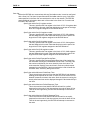
1. The ladder code builds an explicit request message in a group of %R registers.
2. The ladder code plugs the start of and length of the transmit and receive buffers into four
%AQ registers. The transmit and receive buffers must both be located in the %R register
space of the OCS.
3. The ladder code then sets the “Send Explicit Message” command bit.
4. The DNT450 periodically checks the “Send Explicit Message” command bit.
5. If the “Send Explicit Message” command bit is set, processing of the explicit request begins.
This command bit must remain on until success or error status is returned.
6. The four %AQ registers are examined and checked for validity.
7. The DNT450 requests the PLC to send the transmit buffer.
8. The DNT450 then checks the MACID contained in the transmit buffer. Several checks take
place, MACID out-of-range, referenced node not configured and referenced node not Online.
9. Then the message is formatted and sent to the referenced node.
10. When the response message is received, a check is made to see if the allocated receive
buffer is large enough to accept the response message.
11. The message is then sent to the block of %R registers designated as the receive buffer.
12. The Explicit Transaction Complete bit is then set.
13. If there were any errors detected in any of the previous steps, the process is aborted and the
appropriate error status bit along with the Explicit Transaction Complete bit are set.
See Chapter 4 for descriptions of all of the command, status and error bits.
5.2
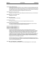
Building Explicit Messages
In the following example, let’s assume that we want to read the polled consumption size from the
node at MACID 3, we also want to locate the transmit buffer at %R101, the receive buffer at
%R51 and we will also allocate 20 bytes to the receive buffer.
BYTE
NUMBER
0
1
2
3
4
5
6
REGISTER
NUMBER
R101 LSB
R101 MSB
R102 LSB
R102 MSB
R103 LSB
R103 MSB
R103 LSB
DESCRIPTION
MACID (Node Address)
Service Code (Get Attribute Single)
Class ID (Connection Class)
Instance ID (Polled Connection)
Attribute # (Consumption Size)
TRANSMIT
BUFFER DATA
03
14
05
00
02
00
07
PAGE 26
CH. 5
19 APR 2002
REGISTER
%AQ1
%AQ2
%AQ3
%AQ4
DESCRIPTION
Start of Transmit Buffer
Number of Bytes to Transmit
Start of Receive Buffer
Receive Buffer Allocation Size
SUP0462-01
VALUE
101
7
51
20
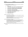
In the following example we want to write the polled expected packet rate to the node at MACID
3, we also want to locate the transmit buffer at %R101, the receive buffer at %R51, we will also
allocate 20 bytes to the receive buffer.
BYTE
NUMBER
0
1
2
3
4
5
6
7
8
REGISTER
NUMBER
R101 LSB
R101 MSB
R102 LSB
R102 MSB
R103 LSB
R103 MSB
R104 LSB
R104 MSB
R105 LSB
REGISTER
%AQ1
%AQ2
%AQ3
%AQ4
5.3
DESCRIPTION
MACID (Node Address)
Service Code (Set Attribute Single)
Class ID (Connection Class)
Instance ID (Polled Connection)
Attribute (Expected Packet Rate)
Data Value Low Byte
Data Value High Byte
DESCRIPTION
Start of Transmit Buffer
Number of Bytes to Transmit
Start of Receive Buffer
Receive Buffer Allocation Size
TRANSMIT
BUFFER DATA
03
16
05
00
02
00
07
E8(Hex)
03
VALUE
101
9
51
20
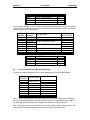
How to Interpret Explicit Response Messages
The normal, expected response from an Explicit Message is the Acknowledge Message:
BYTE
EXAMPLE
DESCRIPTION
NUMBER
Number of
0
Xx
bytes received
1
Xx
2
MACID
01
3
*Service Code
0x90(Hex)
4
Optional Data
Xx
Optional Data
Xx
Optional Data
Xx
n
Optional Data
Xx
* Previously sent Service Code (0x10) + 0x80
Note: The Most Significant Bit in the Service Code byte is used as a Response Bit indicating
that the command was properly received. [Service Code 0x10 + Response Bit 0x80 = 0x90]. If
any extra data needs to be returned, that data will be placed into subsequent bytes.
Note: The number of bytes received value is the number of bytes of the message placed in the
receive buffer including the two bytes devoted to the number of bytes received.
SUP0462-01
5.4
19 APR 2002
PAGE 27
CH. 5
Explicit Message Errors
In the case that an Explicit Message requests a function that cannot be performed by the
referenced node, an Explicit Error Message will be returned.
An Explicit Error Message takes the following form:
Byte
Number
Description
0
1
2
3
4
5
Number of bytes
received
MACID
Service Code
General Error Code
Additional Error Code
Example
(values in
HEX)
06
00
01
94
xx
xx
Word
Offset
Value
(from
example)
%R1
0006
%R2
0x9401
%R3
xxxx
An Error is indicated by a 0x94 in the service code byte. This indicates that the referenced node
has detected an error and the two bytes following indicate the specifics to that error. The next
byte indicates the General Error Code. The last byte contains an Additional Error Code to
indicate additional information. See appendix C for a list of and definitions of General and
Additional Error Codes.
Many DeviceNet manufactures have defined vendor specific error codes. In this case the
General error code will be in the range of 0xD0 to 0xFF (Vendor-specific Object and Class
errors). In these cases the Additional error code can be anything. Consult the documentation
from the node manufacture for more details.
PAGE 28
CH. 5
19 APR 2002
NOTES
SUP0462-01
SUP0462-01
19 APR 2002
PAGE 29
CH. 6
CHAPTER 6: CONFIGURATION
6.1
General
Chapter Six describes the steps necessary to configure the DNT450 module and the OCS it is
attached to. The procedures for using Cscape software are also described.
6.2
Configuration
Configuration is usually completed after the modules are installed. With Cscape, however, OCS
configuration is contained with the source code (.CSP) files. The OCS can be configured before
the modules are installed or even if the OCS is not available. This is a great convenience when
programming must start before the hardware has been received.
6.2.1
Select the Module to be Configured
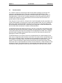
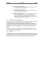
First, invoke Cscape. From the Cscape Main Menu, select Controller | I/O Configure… .
A. Ensure the
correct controller is
selected. To change
controllers, press
CPU Slots and
select the desired
module.
B. You can add an
I/O module to any
slot, but Slot 1 must
not be empty.
Figure 6.1 – Select the Module Slot
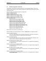
Next, double-click on the empty slot in which the DNT450 module will reside, or click on the
Config button to the right of the slot position. This invokes the Add I/O Module screen. Click on
the Comm tab.
Figure 6.2 – Select the Comm tab
From that dialog, select the DNT450 module, and click OK.
PAGE 30
CH. 6
19 APR 2002
SUP0462-01
Figure 6.3 – DNT450 Module is Added
The screen returns to the Configure I/O dialog box- with the selected slot showing that the
DeviceNet Master module has been added.
It is vital that the module and slot match that of the OCS. Mismatched configurations cause an
I/O Module Mismatch Error during the power-on diagnostics of the OCS.
If the OCS that is to be configured is available and connected to one of the COM ports, the Auto
Config button can be used. Using this option will cause Cscape to read the OCS and display the
modules that are connected to the OCS.
Note: When using Auto Config the user needs to make sure that the SmartStack modules to be
used (e.g.,DNT450) are connected to the OCS prior to using Auto Config.
6.2.2
Configure the Module
First, double click on the DeviceNet module in the I/O configuration screen (Figure 5.4), or click
on the config button next to the DeviceNet module. The following screen will appear:
Figure 6.4 – Module Configuration
SUP0462-01
19 APR 2002
PAGE 31
CH. 6
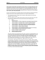
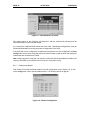
Now, click on the Module Setup tab. Select the Configure button. The DeviceNet network
configuration utility will then open up. The first dialog that will appear is the Network Properties
dialog. This dialog allows the user to set the starting Reference Addresses of the registers and
Baud Rate of the network. The %I size, %AI size, %Q size, %AQ size, %I Ref Addr, %AI Ref
Addr, %Q Ref Addr, and %AQ Ref Addr values are values with respect to the OCS that the
DNT450 is running on. Select the Baud Rate drop down box to configure the baud rate for the
DNT450. Once done configuring this screen, then click OK.
Figure 6.5 – Network properties screen
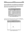
The network view of the configuration utility will appear. The right pane is the Network View
where the user can build a visual representation of a network depicting the DNT450 Master and
all slave nodes (devices). The nodes are configured in this view.
Figure 6.6 – Network View screen
PAGE 32
CH. 6
6.2.3
19 APR 2002
SUP0462-01
Creating the network configuration
The DeviceNet network can now be constructed within the network view display. Before
constructing a network with this utility, it is recommended that one should use the following
method to create the network:
1. Decide what baud rate the network will run at. This is needed for the DNT450 module
configuration as well as the configuration of each individual DeviceNet node. All nodes
including the DNT450 must be configured for the same baud rate.
2. Identify all devices (nodes) that are going to be a part of the network.
3. Is Data Assembly information available for each DeviceNet node in the network? This can be
in the form of printed information in the manufactures manual or in the form of an EDS file
provided by the manufacturer. Note that some EDS files do not provide the nodes’ polled
consumption and production sizes.
4. Assign MACIDs (node addresses) to each DeviceNet node. The MACIDs assigned to each
node is totally arbitrary. The only thing that might have an effect here is the fact that the
DNT450 actually scans the nodes in order by MACID. Gaps can be left in the MACID
assignments to allow for future nodes to be added, if desired. DeviceNet provides for nodes
with lower MACIDs to have a higher network priority. The MACID for the DNT450 can be
assigned any unused address. Every node on the network must be assigned a unique
MACID.
5. All bit type input data must be assigned to a contiguous block of PLC %I registers and all
word type input data must be assigned to a contiguous block of PLC %AI registers.
6. Furthermore, all bit type output data is required to be assigned to a contiguous block of PLC
%Q registers and all word type output data must be assigned to a contiguous block of PLC
%AQ registers.
When these steps are taken, then a visual representation of the network can be constructed
within the network view screen.
SUP0462-01
19 APR 2002
PAGE 33
CH. 6
To add a node, either right click in the right-window pane and select Add New Node, or select
the Net-Edit | Add New Node menu item. Once a new node is visually added to the display, it
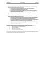
can now be configured in the following manner. Double click on the new node and the following
screen appears.
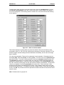
Figure 6.7 – Node connection details
This window displays everything about the connection details of that node (Production sizes,
consumption sizes, %I, %AI, %Q, and %AQ sizes and references). Enter the node MAC ID. The
software program sets the starting reference addresses automatically, but the user can change
them if need be.
Fill in the data assemblies. There are four parameters in each assembly. Each parameter can
be bit data (bits), word data (words), or nothing (none). This value is set in the parameter type
drop down window. The count of each parameter is set in the parameter count drop down box.
The parameter drop down box is used to select any of the four available parameters within an
assembly for editing/viewing. %I and %AI values come together to form the production size of
the node. These are values going from the node onto the network to the DNT450. %Q and %AQ
values come together to form the consumption size of the node. These values are values
coming from the network (The DNT450) into the node. Time out/delay values can be set in this
screen as well (See section 3.7 for details on the time out/delay values). When done configuring
a node, click OK. The process can then be repeated for another node and so forth until the entire
network is done.
Note: Bit data must be in groups of 8.
PAGE 34
CH. 6
19 APR 2002
SUP0462-01
The user can choose to press Network, Auto Remap to remap the nodes in the network.
Caution: Auto Remap reassigns the reference addresses for all nodes so that no gaps are left
in the map. The Auto Remap action cannot be undone and needs to be used with caution.
The Network baud rate and register base addresses can be set at any time by: Selecting
Network, then Properties or by double-clicking anywhere on the screen in the right window
pane. This will bring up the Network Properties (Figure 5.5) screen again.
To see a summary of I/O devices, select Network, I/O Summary. This option is used to display
a summary of the inputs (%Is and %AIs) and outputs (%Qs and %AQs) of every node on the
network configuration. It also displays reference addresses.
To zoom the network view in and out, select View, then Net – Zoom In or Net – Zoom Out.
When done with the configuration utility, click on the close icon (The ‘X’ icon) in the upper right
corner of the utility screen. This will close down the utility and save the configuration for
downloading to the OCS.
NOTE: The module configuration is actually stored in the OCS that it is running on. If the
DNT450 module is placed on a different OCS, then that OCS will have to be configured with the
module and network configuration again. This also means, however, that DNT450 modules can
be swapped on a given OCS unit without the need to reprogram anything since the configuration
stays with the OCS and not the DNT450.
SUP0462-01
19 APR 2002
PAGE 35
CH. 7
CHAPTER 7: DEVELOPING USER SOFTWARE
7.1
Software Support for the Polled Connection
When using the Polled Connection, all inputs from and outputs to the DNT450 are handled by
normal ladder programming techniques to set appropriate data values and read any resulting
data values. Inputs from the DNT450 (and the DeviceNet nodes) can be read from the PLC's %I
and %AI registers. Outputs to the DNT450 (and the DeviceNet nodes) are placed in the PLC's
%Q and %AQ registers. The specific registers used are a function of the configuration of the
DNT450 and of the PLC Configuration.
Data is passed via the DeviceNet Polled Connection automatically. Data is read from or written
to the network devices according to the registers programmed. No extra ladder programming is
required to send or receive data using Polled Messages.
PAGE 36
CH. 7
19 APR 2002
NOTES
SUP0462-01
SUP0462-01
APPENDIX A
19 APR 2002
PAGE 37
APPENDIX A: DNT450 NETWORK OPERATION
A.1
Sequence of Events
The DNT450 follows a predetermined sequence of events as it attempts to communicate with all
of the nodes connected to the network. In an effort to maximize the available DeviceNet
bandwidth, the DNT450 may have message transactions in process with several different nodes
at the same time. Defined below is a very generalized sequence of events:
1.
2.
The DNT450 steps through each node included in its scan list repeatedly.
As each node is examined, several checks are made on the status of the node. These
include:
A.
Is the node on-line? If not go to Establishing a Connection below.
B.
Is a message transaction currently in progress with the node? If not, go to
Sending a Polled Message below.
A.2
Establishing a Connection
There are several steps involved in the establishment of connections with DeviceNet nodes. The
general steps involved include:
1.
8.
Attempt to establish an Explicit connection using the UCMM protocol. If unsuccessful,
attempt to establish an explicit connection using the Group 2 Only protocol. If
unsuccessful, return.
Attempt to establish a Polled connection. If unsuccessful, release the Explicit connection
and return.
Request the node’s Polled Production size. If unsuccessful, release the Explicit and
Polled connections and return.
Compare the nodes Polled Production size to the configuration file. If different, release
the Explicit and Polled connections and return.
Request the node’s Polled Consumption size. If unsuccessful, release the Explicit and
Polled connections and return.
Compare the nodes Polled Consumption size to the configuration file. If different,
release the Explicit and Polled connections and return.
Set the nodes Polled Expected Packet Rate. If unsuccessful, release the Explicit and
Polled connections and return.
Set On Line status for the node and return.
A.3
Send a Polled Message
1.
2.
3.
4.
Read the appropriate %Q and %AQ data from the PLC.
Build a Polled Command message sequence.
Sent the message(s) over the network to the node.
When the Polled response from the node is received, send the response data to the
appropriate PLC %I and %AI registers and return.
A.4
Explicit NOPs
2.
3.
4.
5.
6.
7.
Every few seconds the DNT450 will send an Explicit message containing a NOP to each on line
node. The purpose of this is to keep the nodes’ Explicit connection from timing out.
See ODVA DeviceNet Specifications, Volume I, Chapters 9 and 10, and Appendices A through F
for a complete listing of DeviceNet requirements and specification.
PAGE 38
APPENDIX A
19 APR 2002
NOTES
SUP0462-01
SUP0462-01
APPENDIX B
19 APR 2002
PAGE 39
APPENDIX B: DEVICENET TIMING
B.1
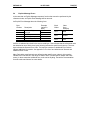
Message Packet Timing
It is not easy to determine the exact transmission time of the DeviceNet Polled scan time. The
table below provides actual timing of single message packets for various baud rates and
message sizes. It must be understood that the table does not take into account the dead time
between the message packets. There are a number of reasons for this dead time, but be assured
that it does exist. The best way to get an accurate handle on the DeviceNet Polled scan time is
to connect a good digital oscilloscope or a DeviceNet protocol analyzer to the DeviceNet cable
and observe the system’s operation.
The amount of data to be transmitted determines the "packet size" and number of packets
necessary. The baud rate determines the amount of time necessary to transmit one packet.
MESSAGE PACKET TRANSMISSION TIMES
Number of Data Bytes in
0
1
2
3
4
Message
Number of BITS in
47
55
63
71
79
message packet
Transmission time @
376 440 504 568 632
125K
Transmission time @
188 220 252 284 316
250K
Transmission time @
94
110 126 142 158
500K
Given a message of 'X' bytes, it is first necessary to determine if
if so how many packets will be sent:
5
6
7
8
87
95
103
111
696
760
824
888
µS
348
380
412
444
µS
174
190
206
222
µS
fragmentation is involved, and
If the size of the message ('X') is eight (8) bytes or less, use the time given in Table 8.
If the size ('X') is more than eight bytes, fragmentation is required:
Number of Full Packets = Message Size / 7
Size of additional packet = (remainder of (message size / 7 ) ) + 1
Time for full packets = Time for 8 bytes, taken from table.
Time for additional packet = Taken from table
Time for full message = Total for all Full Packets + Time for Additional Packet.
B.2
Network Scan Time versus PLC Scan Time
The user should not make any assumptions about the relationship between the PLC scan time
and the DeviceNet Polled scan time. They are totally asynchronous to each other.
Any relationship between the PLC scan time and the DeviceNet Polled scan time can be
determined only with a strong knowledge of the program running in the PLC, the DeviceNet
configuration or by conducting extensive testing.
PAGE 40
APPENDIX B
19 APR 2002
NOTES
SUP0462-01
SUP0462-01
APPENDIX C
19 APR 2002
PAGE 41
APPENDIX C: DEVICENET ERROR CODES
The following DeviceNet General Error Codes are defined within the DeviceNet specification and
are supported by all DeviceNet nodes.
Table C.1 – General Error Codes
Error Code
Name
(in hex)
00 – 01
Reserved
02
Resource
Unavailable
03 – 07
Reserved
08
Service Not
Supported
09
Invalid Attribute
Value
0A
Reserved
0B
Already in
requested mode
0C
Object State
Conflict
0D
Reserved
0E
Attribute Not
Settable
0F
Privilege Violation
10
Device State
Conflict
11
Reply Data Too
Large
12
Reserved
13
Not Enough Data
14
15
16
17
18
19
1A – 1E
1F
20
21 – CF
D0 – FF
Attribute Not
Supported
Too Much Data
Object Does not
Exist
Reserved
No stored attribute
data
store operation
failure
Vendor Specific
error
Invalid parameter
Reserved
Object Class and
Service Errors
Description of error
Resource needed for the object to perform the
requested service were not available
The requested service was not implemented or not
defined for this Object Class/Instance
Invalid attribute data detected
The object is already in the requested mode or state
requested by the service
The object can not perform the requested service in
it's current mode or state
A request to modify a non-modifiable attribute was
received
Permission/privilege check failed
The device's current mode or state prohibits the
requested service
The data to be transmitted is large than the allocated
response buffer
The service did not supply enough data to perform
the requested service
the attribute specified in the request is not supported
The serve supplied more data than was expected
The specified object does not exist in the device
The attribute data of the object was not stored prior to
the requested service
The attribute data of this object was not saved by the
object
Reserved by DeviceNet
A vendor-defined error has occurred. See the
Additional Byte for further information
A parameter associated with the service was
determined to be not valid
Vendor-specific Object and Class errors.
PAGE 42
APPENDIX C
19 APR 2002
SUP0462-01
Table C.2 – Additional Error Codes
Error
Description of error
Code
(in hex)
01
Predefined Master/Slave Connection Set allocation conflict. This is returned
when an Allocate_Master/Slave_Connection_Set request is received and
the
Slave has already allocated the Predefined Master/Slave Connection Set
to another Master.
02
03
04
Invalid Allocation/Release Choice parameter. This is returned when an
Allocate/Release_Master/Slave_Connection_Set request is received and:
1) The Slave does not support the choice specified in the Choice parameter.
2) The Slave was asked to Allocate/Release connection(s) already
allocated/released. The Allocation Choice/Release byte contained all zeros,
an invalid combination of bits, or did not contain the Explicit Message Allocation
Choice when required.
A Group 2 Only Server (UCMM incapable) received a message on the Group 2
Only Unconnected Explicit Request message port that was not an Allocate or
Release message.
Resource required for use with the Predefined Master/Slave Connection Set is
not available.
SUP0462-01
INDEX
19 APR 2002
INDEX
Configuration, 29
Introduction, 15
Configuration, Network, 32
Connectors
DeviceNet I/O (CAN A), 10
Data Assemblies, 14
DeviceNet
Error Codes, 41
Message Packet Timing, 39
Node Priority and Implications, 17
Explicit Messages
Building Explicit Messages, 25
Errors, 27
Interpreting Explicit Response, 26
Explicit NOPs, 37
Fault Table, 17
Features, 7
Fragmentation, 13
LED Indicators, 11
Mapping
Module to PLC, 13
Node to PLC, 13
Message Packets, 13
Network Operation
Establishing Connection, 37
Sequence of Events, 37
Network Timing
Network Scan vs. PLC Scan, 39
Physical Limitations, 13
Polled Messages, sending, 37
Register Requirements, 21
SmartStack
Installing and Removing, 9
Software
Polled Connection, 35
Specifications, 8
Timing, DeviceNet, 39
PAGE 43
PAGE 44
INDEX
19 APR 2002
SUP0462-01