1
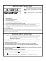
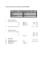
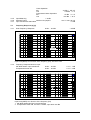
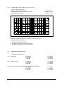
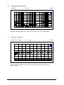
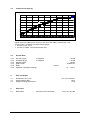
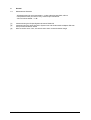
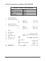
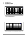
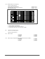
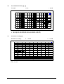
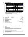
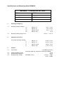
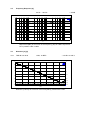
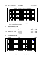
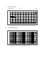
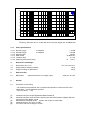
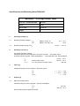
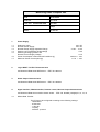
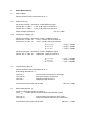
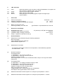
SERVICE MANUAL
DPM 4000
Table of Contents
-
Safety and Service Instructions
Warranty
Measuring data
Bill of materials
Spare parts plan
Circuit diagrams
TELEX / EVI Audio GmbH
- Service Department Hirschberger Ring 45
94315 Straubing
Tel.: ++49-9421/706-342
Fax.: ++49-9421/706-350
e-mail: [email protected]
IMPORTANT SAFETY INSTRUCTIONS
The lightning flash with arrowhead symbol, within an equilateral triangle is intended to alert the user to the presence
of uninsulated “dangerous voltage” within the product’s
enclosure that may be of sufficient magnitude to constitute
a risk of electric shock to persons.
The exclamation point within an equilateral triangle is
intended to alert the user to the presence of important
operating and maintance (servicing) instructions in the
literature accompanying the appliance.
1.
2.
3.
4.
5.
6.
7.
Read these instructions.
Keep these instructions.
Heed all warnings.
Follow all instructions.
Do not use this apparatus near water.
Clean only with a damp cloth.
Do not block any of the ventilation openings.
Install in accordance with the manufactures instructions.
Do not install near any heat sources such as radiators, heat registers, stoves, or other apparatus that produce heat.
Only use attachments/accessories specified by the manufacturer.
Refer all servicing to qualified service personnel. Servicing is required when the apparatus has been
damaged in any way, such as power-supply cord or plug is damaged, liquid has been spilled or objects have fallen
into the apparatus, the apparatus has been exposed to rain or moisture, does not operate normally, or has
been dropped.
8.
9.
10.
For US and CANADA only:
Do not defeat the safety purpose of the grounding-type plug. A grounding type plug has two blades and a third grounding prong.
The wide blade or the third prong are provided for your safety. When the provided plug does not fit into your outlet, consult an
electrican for replacement of the absolete outlet.
IMPORTANT SERVICE INSTRUCTIONS
CAUTION: These servicing instructions are for use by qualified personnel only. To reduce the
risk of electric shock, do not perform any servicing other than that contained in the
Operating Instructions unless you are qualified to do so. Refer all servicing to
qualified service personnel.
1. Security regulations as stated in the EN 60065 (VDE 0860 / IEC 65) and the CSA E65 - 94 have to be obeyed when
servicing the appliance.
2. Use of a mains separator transformer is mandatory during maintenance while the appliance is opened, needs to be
operated and is connected to the mains
3. Switch off the power before retrofitting any extensions, changing the mains voltage or the output voltage.
4. The minimum distance between parts carrying mains voltage and any accessible metal piece (metal enclosure),
respectively between the mains poles has to be 3 mm and needs to be minded at all times.
The minimum distance between parts carrying mains voltage and any switches or breakers that are not connected
to the mains (secondary parts) has to be 6 mm and needs to be minded at all times.
5. Replacing special components that are marked in the circuit diagram using the security symbol (Note) is only permissible
when using original parts.
6. Altering the circuitry without prior consent or advice is not legitimate.
7. Any work security regulations that are applicable at the location where the appliance is being serviced have to be strictly
obeyed. This applies also to any regulations about the work place itself.
8. All instructions concerning the handling of MOS - circuits have to be observed.
Note:
SAFETY COMPONENT (HAS TO BE REPLACED WITH ORIGINAL PART ONLY)
1-2
GARANTIE
WARRANTY
GARANTIE
Das Werk leistet Garantie für alle
nachweisbaren Material- und Fertigungsfehler für die Dauer von 36
Monaten ab Verkauf.
Garantieleistungen werden nur
dann anerkannt, wenn gültige, d.h.
vollständig ausgefüllte Garantieunterlagen vorliegen.
Von der Garantie ausgenommen
sind alle Schäden, die durch falsche
oder unsachgemäße Bedienung
verursacht werden. Bei Fremdeingriffen oder eigenmächtigen Änderungen erlischt jeder Garantieanspruch.
The manufacturer’s warranty covers all substantial defects in materials and workmanship for a period
of 36 months from the date of
purchase.
Liability claims are accepted solely,
when a valid – correctly and completely filled out – Warranty Registration form is presented by the original
owner of the product. The warranty
does not cover damage that results
from improper or inadequate treatment or maintenance. In case of
alteration or unauthorized repairs,
the warranty is automatically terminated.
La garantie constructeur couvre
tous les défauts matériels et de
main d’œuvre pour une période de
36 mois à compter de la date
d’achat. La garantie ne sera reconnue que si la Carte de Garantie,
correctement et complètement
remplie, est présentée par l’acheteur d’origine du produit. Les dommages dus à un mauvais
maniement de l’appareil, à un traitement ou une maintenance incorrects ou inadéquats ne sont pas
garantis. Toute modification ou intervention effectuée par une personne non qualifiée entraîne la
résiliation automatique de la garantie.
GmbH • Hirschberger Ring 45 • 94315 Straubing •Telefon (09421) 706-0 •Telefax (09421) 706-265
Änderungen vorbehalten. Subject to change without prior notice. Printed in Germany 07. 07. 1999 /
Internet: http:// www.dynacord.de
Technical Specifications and Measured Data DPM 4000
NRS 90215 - 2 Ch. paging console input 81332
EDP No.
121 665
Editor
Kaup
Creation Date
06.05.98
1.
Operation Voltage [1]
1.1
Nominal Operation Voltage
UA+
UAUD+
UB1
1.2
Nominal Operation Range of UB1
2.
Operation Current [1]
at Nominal Operation Voltages
IA+
IAID+
IB1
3.
Audio Inputs
3.1
3.2
3.3
3.4
3.5
Connections
Input Impedance, balanced
Nominal Input Level
Max. Input Level
Input Balancing
CN3 pin 1a
CN3 pin 1b
CN3 pin 4a, 4b
CN3 pin 16b
+12 V ± 10 %
-12 V ± 10 %
+5 V ± 5 %
+24 V
+21.6 V ... +31.2 V
inputs open
87 mA
17 mA
60 mA
16 mA
± 10 %
± 10 %
+ 10 %
+ 10 %
2 x RJ45, 8-pole
20 kΩ
0 dBu / 775 mV
+12 dBu / 3 V
≥ -30 dB
3.6
Frequency Response [2]
Frequency Response
± 0.5dB
20 Hz ... 20 kHz
DPM4000
PCB 81332
A_D FREQUENCY
-6
-8
-10
d
B
F
S
1
-12
-14
2
-16
-18
-20
20
50
100
200
500
1k
2k
5k
10k
20k
Hz
Digital Input Level (dBFS) as a function of the frequency (Hz), input level = 0 dBu
1
2
without input transformer
with NRS 90208, Line input transformer
3.7
Distortion [2] [3]
3.7.1
THD+N relative to the level
≤ -80 dB = 0.01 %
0 dBu
DPM4000
PCB 81332
THD+N vs LEVEL
1
-40
0.5
-50
0.2
0.1
-60
0.05
-70
d
B
F
S
0.02
0.01
-80
0.005
-90
0.002
0.001
-100
0.0005
-110
0.0002
-120
-40
0.0001
-35
-30
-25
-20
-15
-10
-5
+0
+5
+10
+15
+20
dBu
Distortion (THD+N absolute) as a function of the input level (dBu), measured at 1 kHz
%
F
S
3.7.2
THD+N relative to the frequency
DPM4000
20 Hz ... 20 kHz, 0 dBu
PCB 81332
≤ -80 dB = 0.01 %
THD+N vs FREQUENCY
-60
0.1
0.05
-70
0.02
-80
0.01
d
B
F
0.005
-90
2
F
0.002
S
-100
%
1
S
0.001
0.0005
-110
0.0002
-120
20
0.0001
50
100
200
500
1k
2k
5k
10k
20k
Hz
Distortion (THD+N absolute) as a function of the frequency (Hz),
measured at 0 dBu input level
1
2
3.8
without transformer
with NRS 90208, Line input transformer
Interference Voltages [2]
Inputs terminated with 50 Ω
≤ -96 dBFS
≤ -100 dBFS
≤ -86 dBFS
unweighted
A-weighted
CCIR-468
3.9
Crosstalk Attenuation [2]
Crosstalk
≤ -80 dB
1 kHz
DPM4000
PCB 81332
CROSSTALK
-40
-50
-60
-70
-80
d
B
-90
-100
-110
-120
-130
-140
20
50
100
200
500
1k
2k
Hz
Crosstalk Attenuation (dB) as a function of the frequency (Hz),
measured at 0 dBu input level
5k
10k
20k
3.10
Converter Linearity [2]
Deviation in Linearity
< ± 0.5 dB
0 ... -80 dB
DPM4000
PCB 81332
A/D LINEARITY
+2
+1.5
+1
+0.5
d
B
F
S
-0
-0.5
-1
-1.5
-2
-100
-90
-80
-70
-60
-50
-40
-30
-20
-10
+0
dBr
Digital input level (dBFS) as a function of the analog input level (dBr),
measured at 1 kHz, 0 dBr = 0 dBFS
3.11
General Data
3.11.1
3.11.2
3.11.3
3.11.4
3.11.5
3.11.6
Dynamic [2]
A-weighted
S/N Ratio [2]
A-weighted
Sampling Rate
Data Format
Delay
Operation Temperature Range
4.
Control Interfaces
at CN1, CN2 pins 4 and 5
5.
> 100 dB
> 100 dB
48 kHz
18 Bit linear
0.52 ms
+5 ... +40 °C
RS485 Standard
Power Supply for the DPC 4000 [1] [3]
at CN1, CN2, pins 1 and 2
5.1
5.2
5.3
Nominal Output Voltage
24 V DC -10% +30%
Output Current
adjustable
330 mA, 660 mA, 990 mA
Electronically programmable fuses against overload and short-circuit
Power-Off at Undervoltage
if UB1 < +17 V - 10%
6.
Size and Weight
6.1
6.2
6.3
Dimensions W x H x D
Weight without NRS
Weight including 2 x NRS 90208
7.
Extensions
7.1
NRS 90208
8.
General
8.1
Measurement Remarks
37.5 x 81 x 248 mm
152 g
220 g
Line Input Transformer
order No. 121 641
- All measurement at room temperature – unless otherwise specified,
without input transformer
- All level values stated ± 1 dB
[1]
[2]
[3]
measured using the Philips Digital multi-meter PM2517X
measured using the Audio Precision System One and Serial Interface Adapter SIA-322
via Input Service Board 83108
Output current adjusted via parser-command ' Fuse '
Technical Specifications and Measured Data DPM 4000
NRS 90216 - Mic/Line + 2 Aux Input 81335
EDP No.
121 666
Editor
Kaup
Creation Date
29.04.98
1.
Operation Voltage [1]
1.1
Nominal Operation Voltages
UA+
UAUD+
2.
CN1 pin 1a
CN1 pin 1b
CN1 pin 4a, 4b
+12 V ± 10 %
-12 V ±10 %
+5 V ± 5 %
CN1 pin 1a
CN1 pin 1b
CN1 pin 4a, 4b
110 mA ± 10 %
35 mA ± 10 %
4 mA ± 10 %
Operation Current [1]
at Nominal Operation Voltages
IA+
IAID+
3.
Inputs
3.1
AUX -Inputs
3.1.1
3.1.2
3.1.3
3.1.4
3.1.5
Connections
Input Impedance
Nominal Input Level
Max. Input Level
Level Matching
3.2
Mic / Line Input
3.2.1
Connections
3.2.2
3.2.3
Input Impedance Mic
Line
Nominal Input Level
3.2.4
Max. Input Level
DYNACORD
81335
2 x 2 RCA-type, unbalanced
10 kΩ
-10 ... +12 dBu / 250 mV ... 3 V
+12 dBu / 3 V
VR2, VR3
1 x XLRF-type connector
electronically balanced, transformer optional
3,6 kΩ
10 kΩ
Mic
-54 ... -14 dBu / 1.5 ... 155 mV
Line
-24 ... +16 dBu / 50 mV ... 5 V
18.07.00
1/7
3.2.5
3.2.6
3.2.7
Input Balancing
Phantom Power
Input Transformer Attenuation
3.3
Frequency Response [2] [3]
3.3.1
linear Frequency Response
Linear Operation
Mic
Line
Compressor/Limiter Operation
Mic
Line
≥ -30 dB
switched via jumpers
-14 dBu / 155 mV
+16 dBu / 5 V
+5 dBu / 1.4 V
+30 dBu / 25 V
+24 V / max. 20 mA
1.5 dB
± 0.5dB
20 Hz ... 20 kHz
DPM4000
PCB 81335
A_D FREQUENCY
-0
-1
-2
AUX
-3
-4
d
B
F
S
-5
-6
MIC/LINE
-7
-8
-9
-10
20
50
100
200
500
1k
2k
5k
10k
20k
Hz
Input level (dBFS) as a function of the frequency (Hz), JP2 set to 'LIN'
3.3.2
Frequency Response Mic/Line Input
with NRS 90233 input transformer
Compressor/Limiter ON
DPM4000
20 Hz ... 20 kHz
20 Hz ... 20 kHz
PCB 81335
+ 0.5 / - 1 dB
+ 0.5 / - 2 dB
A_D FREQUENCY
-0
-1
-2
1
-3
-4
d
B
F
S
-5
-6
2
-7
-8
-9
-10
20
50
100
200
500
1k
2k
5k
10k
20k
Hz
Input level (dBFS) as a function of the frequency (Hz)
1 with NRS 90233 Mic/Line input transformer
2 Compressor/Limiter ON, JP2 set to 'COMP', input level +20 dBu
DYNACORD
81335
18.07.00
2/7
3.4
Distortion [2] [3]
3.4.1
THD+N relative to the level
DPM4000
≤ -80 dB = 0.01 %
0 dBu
PCB 81335
A_D THD+N vs LEVEL
-40
1
-45
0.5
-50
-55
0.2
-60
0.1
-65
d
B
F
S
0.05
-70
-75
0.02
AUX
-80
%
F
S
0.01
MIC/LINE
-85
0.005
-90
0.002
-95
-100
-80
0.001
-70
-60
-50
-40
-30
-20
-10
+0
+10
+20
dBu
Distortion (THD+N absolute) as a function of the input level (dBu),
measured at 1 kHz
3.4.2
THD+N relative to the frequency
DPM4000
20 Hz ... 20 kHz, 0 dBu
PCB 81335
≤ -80 dB = 0.01 %
THD+N vs FREQUENCY
-40
1
-45
0.5
-50
d
B
F
S
-55
0.2
-60
0.1
-65
0.05
-70
0.02
-75
-80
%
F
S
0.01
-85
0.005
AUX
-90
-95
-100
20
0.002
MIC/LINE
0.001
50
100
200
500
1k
2k
5k
10k
20k
Hz
Distortion (THD+N absolute) as a function of the frequency (Hz),
measured at 0 dBu input level
DYNACORD
81335
18.07.00
3/7
3.4.3
THD+N relative to the frequency Mic/Line Input
1 kHz, at 0 dBu input level
Linear, without input transformer
With NRS 90233, Mic/Line Input Transformer
With Compressor/Limiter
DPM4000
PCB 81335
≤ -80 dB = 0.01 %
≤ -80 dB = 0.01 %
≤ -60 dB = 0.1 %
THD+N vs FREQUENCY
-40
1
0.5
-50
0.2
-60
d
B
F
S
0.1
3
0.05
-70
0.02
-80
%
F
S
0.01
2
0.005
-90
0.002
1
-100
20
50
100
200
500
1k
2k
5k
10k
20k
0.001
Hz
Distortion (THD+N absolute) as a function of the frequency (Hz),
measured at 0 dBu input level
1 linear, without input transformer
2 with NRS 90233, Mic/Line input transformer
3 Compressor/Limiter ON, JP2 set to 'COMP'
3.5
Interference Voltages [2] [3]
Inputs terminated with 50 Ω
3.5.1
AUX Input
unweighted
A-weighted
CCIR-468
≤ -96 dBFS
≤ -100 dBFS
≤ -86 dBFS
3.5.2
Mic/Line Input
unweighted
A-weighted
CCIR-468
≤ -92 dBFS
≤ -95 dBFS
≤ -83 dBFS
3.5.3
Mic/Line Input, Compressor/Limiter ON (JP2 set to 'COMP')
unweighted
A-weighted
CCIR-468
DYNACORD
81335
≤ -75 dBFS
≤ -78 dBFS
≤ -65 dBFS
18.07.00
4/7
3.6
Crosstalk Attenuation [2] [3]
Crosstalk
≤ -80 dB
1 kHz
DPM4000
PCB 81335
CROSSTALK
-40
-50
-60
-70
d
B
-80
-90
-100
-110
-120
20
50
100
200
500
1k
2k
5k
10k
20k
Hz
Crosstalk Attenuation (dB) as a function of the frequency (Hz), measured at 0 dBu
3.7
Converter Linearity [2]
Deviation in Linearity
< ± 0.5 dB
0 ... -80 dB
DPM4000
PCB 81335
A/D LINEARITY
+2
+1.5
+1
+0.5
d
B
F
S
-0
-0.5
-1
-1.5
-2
-100
-90
-80
-70
-60
-50
-40
-30
-20
-10
+0
dBr
Digital input level (dBFS) as a function of the input level (dBr), measured at 1 kHz,
0 dBr = 0 dBFS
DYNACORD
81335
18.07.00
5/7
3.8
Compressor/Limiter [2]
DPM4000
PCB 81335
COMP/LIMITER
+10
+0
-10
-20
d
B
F
S
2
-30
1
-40
-50
-60
-70
-80
-80
-70
-60
-50
-40
-30
-20
-10
+0
+10
dBu
Digital input level (dBFS) as a function of the input level (dBu), measured at 1 kHz,
S1 set to 'MIC', controls at counterclockwise margin
1 JP2 set to 'LIN', linear
2 JP2 set to 'COMP', Compressor/Limiter ON
3.9
General Data
3.9.1
3.9.2
3.9.3
3.9.4
3.9.5
3.9.6
Dynamic [2] [3]
A-weighted
S/N Ratio [2] [3]
A-weighted
Sampling Rate
Data Format
Delay
Operation Temperature Range
4.
Size and Weight
4.1
4.2
4.3
Dimensions W x H x D
Weight without NRS
Weight including NRS 90233
5.
Extensions
5.1
NRS 90233
DYNACORD
> 95 dB
> 95 dB
48 kHz
18 Bit linear
0.52 ms
37.5 x 81 x 252 mm
160 g
173 g
Mic/Line Input Transformer
81335
+5 ... +40 °C
order No. 121 682
18.07.00
6/7
6.
General
6.1
Measurement Remarks
- All measurement at room temperature – unless otherwise specified, without
Compressor/Limiter (JP2 set to 'LIN'), without input transformer
- All level values stated ± 1 dB
[1]
[2]
[3]
measured using the Philips Digital multi-meter PM2517X
measured using the Audio Precision System One and Serial Interface Adapter SIA-322
via Input Service Board 83108
Mic/Line switch set to 'Line', all controls set to their counterclockwise margin
DYNACORD
81335
18.07.00
7/7
Technical Specifications and Measured Data DPM 4000
NRS 90217 2 Channel
EDP No.
121 667
EDP No. measured data
813378
Editor
Wendler
Creation date
03.09.98
1.
Operation Voltage [1]
1.1
Nominal Operation Voltage
2.
Mic/Line Input 81337
UA+
UAUD+
CN1 pin 1a
CN1 pin 1b
CN1 pin 4a, 4b
+12 V ± 10 %
-12 V ± 10 %
+5 V ± 5 %
IA+
IAID+
CN1 pin 1a
CN1 pin 1b
CN1 pin 4a, 4b
118 mA ± 10 %
38 mA ± 10 %
5 mA ± 10 %
Operation Current [1]
at Nominal Operation Voltage
3.
Inputs
3.1
Mic / Line Input
3.1.1
Connections
3.1.2
3.1.3
Input Impedance Mic
Line
Nominal Input Level
3.1.4
Max. Input Level
3.1.5
3.1.6
10 kΩ
Mic
Line
-54 ... -14 dBu / 1.5 ... 155 mV
-24 ... +16 dBu / 50 mV ... 5 V
Linear Operation
Mic
Line
Compressor/Limiter Operation
Mic
Line
≥ -30 dB
switched via jumpers
Input Balancing
Phantom Power
DYNACORD
2 x XLRF-type connector,
electronically balanced, transformer optional
3.6 kΩ
81337
-14 dBu / 155 mV
+16 dBu / 5 V
+5 dBu / 1,4 V
+30 dBu / 25 V
+24 V / max. 20 mA
18.07.00
1/6
3.3
Frequency Response [2], [3]
3.3.1
Frequency Response MIC/LINE Input
Frequency Response, linear
with NRS 90233 Input Transformer
Compressor/Limiter ON
DPM4000
PCB 81337
FREQUENCY
-0
± 0.5dB
+ 0.5 / - 1 dB
+ 0.5 / - 2 dB
20 Hz ... 20 kHz
20 Hz ... 20 kHz
20 Hz ... 20 kHz
A_D
-1
1
-2
-3
2
-4
d
B
F
S
-5
3
-6
-7
-8
-9
-10
20
50
100
200
500
1k
2k
5k
10k
20k
Hz
Input level (dBFS) as a function of the frequency (Hz) ), input level = 0 dBu
1 Compressor/Limiter OFF, JP3 and JP4 set to 'LIN'
2 with NRS 90233 input transformer Mic/Line
3 Compressor/Limiter ON, JP3 and JP4 set to 'COMP'
3.4
Distortion
3.4.1
Distortion MIC/LINE Input [2],[3]
3.4.1.1 THD+N relative to the level
DPM4000
≤ -80 dB = 0.01 %
0 dBu
PCB 81337
A_D THD+N vs LEVEL
-40
1
-45
0.5
-50
0.2
-55
-60
d
B
F
S
0.1
-65
0.05
-70
0.02
-75
-80
%
F
S
0.01
-85
0.005
-90
0.002
-95
-100
-80
0.001
-70
-60
-50
-40
-30
-20
-10
+0
+10
+20
dBu
Distortion (THD+N absolute) as a function of the input level (dBu), measured at 1 kHz
DYNACORD
81337
18.07.00
2/6
3.4.1.2 THD+N relative to the frequency
1 kHz, at 0 dBu input level
Linear, without input transformer
with NRS 90233, input transformer Mic/Line
with Compressor/Limiter
DPM4000
PCB 81337
≤ -80 dB = 0.01 %
≤ -80 dB = 0.01 %
≤ -60 dB = 0.1 %
THD+N vs FREQUENCY
-40
1
-45
0.5
-50
0.2
-55
-60
d
B
F
S
0.1
3
-65
0.05
-70
-75
2
0.02
-80
S
0.01
-85
-90
%
F
0.005
1
0.002
-95
-100
20
0.001
50
100
200
500
1k
2k
5k
10k
20k
Hz
Distortion (THD+N absolute) as a function of the frequency (Hz),
1 Linear, without input transformer
2 with NRS 90233, input transformer Mic/Line
3 Compressor/Limiter ON, JP3 and JP4 set to 'COMP'
3.5
Interference Voltages [2], [3]
Inputs terminated with 50 Ω
3.5.1
Mic/Line Input
≤ -92 dBFS
≤ -95 dBFS
≤ -83 dBFS
unweighted
A-weighted
CCIR-468
3.5.2
Mic/Line Input, Compressor/Limiter ON (JP3 and JP4 set to 'COMP')
unweighted
A-weighted
CCIR-468
DYNACORD
81337
≤ -75 dBFS
≤ -78 dBFS
≤ -65 dBFS
18.07.00
3/6
3.6
Crosstalk Attenuation [2], [3]
Crosstalk
≤ -80 dB
1 kHz
DPM4000
PCB 81337 CROSSTALK
-40
-50
-60
2
-70
d
B
-80
1
-90
-100
-110
-120
20
50
100
200
500
1k
2k
5k
10k
20k
Hz
Crosstalk Attenuation (dB) as a function of the frequency (Hz), measured at 0 dBu
1 Input signal at the MIC/LINE input A (measured at input B)
2 Input signal at the MIC/LINE input B (measured at input A)
3.7
Converter Linearity [2]
Deviation in Linearity
< ± 0.5 dB
0 ... -80 dB
DPM4000
PCB 81337
A/D LINEARITY
+2
+1.75
+1.5
+1.25
+1
+0.75
+0.5
d
B
F
S
+0.25
-0
-0.25
-0.5
-0.75
-1
-1.25
-1.5
-1.75
-2
-100
-90
-80
-70
-60
-50
-40
-30
-20
-10
+0
dBr
Digital input level (dBFS) as a function of the input signal (dBr), measured at 1 kHz,
0 dBr = 0 dBFS
DYNACORD
81337
18.07.00
4/6
3.8
Compressor/Limiter [2], [3]
DPM4000
PCB 81337
A_D FREQUENCY
+10
+0
-10
2
-20
d
B
F
S
1
-30
-40
-50
-60
-70
-80
-80
-70
-60
-50
-40
-30
-20
-10
+0
+10
dBu
Digital input level (dBFS) as a function of the input level (dBu), measured at 1 kHz,
S1, S2 set to 'MIC', all controls at their counterclockwise margin
1 JP3 and JP4 set to 'LIN', linear
2 JP3 and JP4 in set to 'COMP', Compressor/Limiter ON
3.9
General Data
3.9.1
3.9.2
3.9.3
3.9.4
3.9.5
3.9.6
Dynamic [2] [3] [4]
A-weighted
S/N Ratio [2] [3] [4]
A-weighted
Sampling Rate
Data Format
Delay
Operation Temperature Range
6.
Size and Weight
6.1
6.2
6.3
Dimensions W x H x D
Weight without NRS
Weight including 2 x NRS 90233
7.
Extensions
7.1
NRS 90233
8.
General
8.1
Measurement Remarks
> 95 dB
> 95 dB
48 kHz
18 Bit linear
0.52 ms
Input Transformer Mic/Line
+5 ... +40 °C
37.5 x 81 x 252 mm
160 g
186 g
order No. 121 682
- All measurement at room temperature – unless otherwise specified, without
Compressor/Limiter (JP3 and JP4 set to 'LIN'), without input transformer
- All level values stated ± 1 dB
[1]
[2]
[3]
measured using the Philips Digital multi-meter PM2517X
measured using the Audio Precision System One and Serial Interface Adapter SIA-322
via Input Service Board 83108
Mic/Line switch set to 'Line',
DYNACORD
81337
18.07.00
5/6
Specifications and Measuring Datas DPM4000
NRS 90218 - 2 Channel Line Out 82222
EDP No. measured data
822228
Editor
Kaup
Issue Date
21.04.98
Pages
5
1.
Operating Voltage [1]
1.1
Nominal operating voltages
UA+
UAUD+
UB1
1.2
Nominal operating range of UB1
2.
Operating Current [1]
CN1 pin 1a
CN1 pin 1b
CN1 pin 4a, 4b
CN1 pin 16b
+12 V ± 10 %
-12 V ± 10 %
+5 V ± 5 %
+24 V
+21.6 V ... +31.2 V
At nominal operating voltages
IA+
IAID+
IB1
3.
Outputs
3.1
Connections
3.2
3.3
3.4
Output impedance (bal.)
Nominal load impedance
Nominal output voltage
CN1 pin 1a
CN1 pin 1b
CN1 pin 4a, 4b
CN1 pin 16b
50 mA ± 10 %
25 mA ± 10 %
25 mA ±10 %
17 mA ± 10 %
2 x XLRM-type socket,
electrically balanced, transformer optionally available
114 Ω
600 Ω
selectable via JP1
775 mV = 0 dBu
1.55V = +6 dBu
3.5
Frequency Response [2]
± 0.5dB
20 Hz ... 20 kHz
DPM4000
PCB 82222
D-A FREQUENCY
+10
+8
+6
+4
d
B
u
+2
+0
-2
-4
-6
20
50
100
200
500
1k
2k
5k
10k
20k
Hz
Output level (dBu) as a function of the frequency (Hz) at 0 dBFS input level
JP1 in position 0 dBu / 6 dBu
3.6
Distortion [2] [3]
3.6.1
THD+N over level
DPM4000
≤ -85 dB = 0.005 %
1kHz, -6 dBFS
PCB 82222
D-A THD+N vs LEVEL
-20
10
5
-30
2
-40
1
0.5
-50
0.2
d
B
-60
0.1
0.05
-70
0.02
-80
0.01
0.005
-90
0.002
-100
0.001
-70
-60
-50
-40
-30
-20
-10
+0
dBFS
Distortion (THD+N) as a function of the level (dBFS), measured at 1 kHz
%
3.6.2
THD+N over frequency
≤ -85 dB = 0.005 %
1kHz, -6 dBFS
DPM4000
PCB 82222
D-A THD+N vs FREQUENCY
-30
-35
3
2
-40
1
-45
0.5
-50
d
B
-55
0.2
-60
0.1
-65
0.05
2
-70
%
0.02
-75
-80
0.01
1
-85
0.005
-90
0.002
-95
-100
20
0.001
50
100
200
500
1k
2k
5k
10k
20k
Hz
Distortion (THD+N) as a function of the frequency (Hz), measured at -6 dBFS
1. without output transformer
2. with output transformer, NRS 90227
3.7
Interference Voltages [2] [4]
3.7.1
with Signal < -120 dBFS
U Fremd (Q-Peak)
U CCIR (Q-Peak)
U A bew. (RMS)
≤ 44 µV = -85 dBu
≤ 110 µV = -77 dBu
≤ 22 µV = -91 dBu
3.7.2
with Digital Zero - Signal
U Fremd (Q-Peak)
U CCIR (Q-Peak)
U A bew. (RMS)
≤ 12 µV = -96 dBu
≤ 27 µV = -89 dBu
≤ 5.5 µV = -103 dBu
3.8
Crosstalk Attenuation [2]
Crosstalk
≤ -95 dB
1 kHz
DPM4000 PCB 82222
D-A CROSSTALK
-40
-50
-60
-70
-80
d
B
-90
-100
-110
-120
-130
20
50
100
200
500
1k
2k
5k
10k
20k
Hz
Crosstalk attenuation (dB) as a function of the frequency (Hz), measured at 0 dBFS
3.9
Converter Linearity [2]
Linearity deviation
< ± 0.5 dB
0 ... -80 dB
DPM4000
PCB 82222
D-A I/O LINEARITY
+2
+1.5
+1
+0.5
d
B
r
-0
-0.5
-1
-1.5
-2
-100
-90
-80
-70
-60
-50
-40
-30
-20
-10
+0
dBFS
Output level (dBr) as a function of the input level (dBFS), measured at 500 Hz
3.10
Frequency Spectrum [2] [5]
DPM 4000 PCB 82222
D-A FFT SPECTRUM ANALYSIS
+0
-20
-40
-60
d
B
r
-80
-100
-120
-140
-160
20
50
100
200
500
1k
2k
Hz
Frequency spectrum 20 Hz - 20 kHz with Digital Zero - Signal
5k
10k
20k
DPM 4000
PCB 82222
D-A FFT SPECTRUM ANALYSIS
+0
-20
-40
-60
d
B
r
-80
-100
-120
-140
-160
20
50
100
200
500
1k
2k
5k
10k
20k
Hz
Frequency spectrum 20 Hz - 20 kHz with sine wave input signal and -20 dBFS-level
3.11
Other Specifications
3.11.1
3.11.2
3.11.3
3.11.4
3.11.5
3.11.6
Dynamic [2] [4]
A-weighted
S/N-ratio [2] [4]
A-weighted
Sampling rate
Data format
Traverse delay
Operating temperature range
4.
Dimensions and Weight
4.1
4.2
4.3
Dimensions W x H x D
Weight without extensions (NRS)
Weight including 2x NRS 90227
5.
Extension-Kits
5.1
NRS 90227
6.
General
6.1
Comments on the testing
output transformer for a single output
> 97 dB
> 109 dB
48 kHz
20-Bit linear
0.3 ms
+5 ... +40 °C
37.5 x 81 x 247 mm
160 g
255 g
order No. 121 679
- All measurement performed with a nominal load impedance of 600 Ω and at room
temperature – unless otherwise specified
- All level values 1 dB
[1]
[2]
[3]
[4]
[5]
measured using the Philips Digital Multi-Meter PM2517X
measured using the Audio Precision System One and Serial Interface Adapter SIA-322
via Output Service Board 83109
Measurement bandwidth 22 Hz ... 22 kHz, with 20 kHz Lo-Pass Filter
measured with the JP1 set to +6 dBu
FFT with 2,000 dots, average of 16 test
Specifications and Measuring Datas DPM 4000
NRS 90219 - 8 I/O Logic Control 86241
EDP No. measured data
862418
Editor
Kaup
Issue Date
30.04.98
Pages
1
1.
Operating Voltage [1]
1.1
Nominal operating voltages
UD+
UB1
1.2
Nominal operating range of UB1
2.
Operating Current [1]
CN5 pin 2a, 2b, 2c
CN5 pin 16a, 16b, 16c
+5 V ± 5 %
+24V
+21.6 V ... +31.2 V
At nominal operating voltages,
measured using the service program ' /Service/Logic/Out ' - all outputs active,
as well as service program ' /Service/Start/Slave ' - NU-output with max. 500mA loaded
ID+
IB1
IB1 max
3.
without slave clocks
incl. max. amount of slave clocks
16 mA ± 10 %
130 mA ± 10 %
650 mA
Inputs [1]
measured using the service program ' /Service/Logic/In '
UIN
UIN
UIN max
4.
Outputs [1]
4.1
Slave clock output OUT1
≤ ± 5 V = Low
≥ ± 10 V = High
= ± 31 V
measured using the service program ' /Service/ Start/Slave '
UOUT
Imax
electronically protected against overload
24 V DC
500 mA ± 5 %
4.2
Logic outputs OUT2 ... OUT8
measured using the service program ' /Service/Logic/Out '
floating relay contacts
Imax
5.
Other Specifications
5.1
Operating temperature range
6.
Dimensions and Weight
6.1
6.2
Dimensions W x H x D
Weight
7.
General
7.1
Comments to the testing
at 24 V DC
1A
+5 ... +40 °C
37.5 x 81 x 247 mm
195 g
- All measurement performed at room temperature – unless otherwise specified
[1]
measured using the Philips Digital Multi-Meter PM2517X
Measuring Datas Complete Unit
Unit
DPM 4000
Unit No.
121 619
EDP No. measured data
354 867
Kaup
Date
25.05.98
1.
Power Supply
1.1
1.2
1.3
1.4
1.5
1.6
1.7
Reference Value
Nominal Power Supply
Nominal Power Supply Operation Range
Switching-off Threshold at Undervoltage
Switching-off Paging Station and
Remote Control Supply Voltage
Power Consumption under Nominal Conditions [1]
Maximum Power Consumption [2]
2.
Logic INPUT / OUTPUT Characteristics
24V DC
24V DC
21.6V ... 31,2V
≤ 12V
≤ 17V
360 mA ± 10%
6.7 A ± 10%
see Measured Data sheet NRS 90219 - EDP. No. 862418
3.
Audio Output Characteristics
see Measured Data sheet NRS 90218 - EDP. No. 822228
4.
Signal Interface, RS232-Interface, Remote control, Monitor Output Characteristics
see Measured Data sheet Interface board 80430 - EDP. No. 804308, paragraph. 8, 9, 12, 13
4.1
RS232 Data Transfer
The PC has to be configured according to the following settings:
- 19200 Baud
- 8 Data bits
- 1 Stop bit
- no parity
- Xon/Xoff - protocol
5.
Audio Measurements
5.1
Audio Outputs
Volume values for slot # 3 Out1/Out2 set to “0“
5.1.1
Output Level [3]
Via service program ' /service/sine ' output 0dB sine signal
/service sine 1 1000 0 - 1 kHz, 0 dB output via channel 1
/service sine 2 1000 0 - 1 kHz, 0 dB output via channel 2
Output voltage symmetrical
5.1.2
775 mV = 0 dBu
Interference Voltages [3]
Via service program ' /service/sine ' output –120dB sine signal
/service sine 1 1000 -120 - 1 kHz, -120 dB output via channel 1
/service sine 2 1000 -120 - 1 kHz, -120 dB output via channel 2
U Fremd (Q-Peak)
U CCIR (Q-Peak)
U A bew. (RMS)
≤ 25 µV = -90 dBu
≤ 60 µV = -82 dBu
≤ 13 µV = -96 dBu
Via service program ' /service/sine ' output –200dB sine signal
/service sine 1 1000 -200 - Digital zero output via channel 1
/service sine 2 1000 -200 - Digital zero output via channel 2
U Fremd (Q-Peak)
U CCIR (Q-Peak)
U A bew. (RMS)
5.2
≤ 8 µV = -100 dBu
≤ 20 µV = -92 dBu
≤ 4 µV = -106 dBu
Internal Monitor Bus [4]
Volume values for slot # 3 Out1/Out2 set to “0”
level-setting identical to 5.1.1
/moni vol 0
/moni sel out
/moni idx 1
/moni idx 2
-
Volume value for monitor bus set to 0dB
Switch the output to monitor bus
Assigning output channel 1
Assigning output channel 2
Level at the monitor output with 8Ω load
5.3
620 mV = -2 dBu
External Monitor Bus [4]
Introduce a 1kHz sine signal with a level of
1.27 V RMS = +4.3dBu into the external monitor input (Remote control)
/moni vol +6
/moni sel ext
-
Volume value for monitor bus set to +6dB
Assign the Remote-channel to the monitor bus
Level at the monitor output with 8Ω load
680 mV = -1.1 dBu
6.
LED Indicators
6.1
Fault
6.2
6.3
6.4
Power
Ready
DCF77
7.
Other Data
7.1
7.2
7.3
Pilot Tone Frequency
Operation Temperature Range
Temperature Range for Storing and Transport
7.4
Battery for Real-time Clock
Lithium-type battery 3V / 220 mAh
lights after switching the unit power to ON until initialization is complete, the
unit is ready for operation and in case of fault
lights when the supply voltage is present
lights, when the unit is ready
blinks (blink per second) during signal reception and lights upon
synchronization
15,625 kHz ± 1%
+5 ... +40 °C
-40 ... +70 °C
type CR2032 or equivalentOrd.-No. 354 042
8.
Dimensions and Weight
8.1
8.2
8.3
8.4
Dimensions W x H x D
Installation Depth without Connectors
Installation Depth including Connectors
Weight, equipped as described under [1]
9.
General Remarks
9.1
Measurement was performed using the following equipment:
DC Power supply
Philips Digital Multi-meter PM2517X
Audio Precision System One
9.2
Measurement Comments
19" (483 mm) x 2HE (88 mm) x 337 mm
340 mm
max. 410 mm
6.4 kg
- All measuring performed at normal room temperature, unless differently specified
- All stated levels ± 1 dB
[1]
Nominal Conditions
Unit equipped with
1x NRS 90218 - 2 ch. line out in slot # 3
1x NRS 90219 - 8 I/O logic control in slot # 5
Operation Voltage 24 V DC
All in-/outputs open, PC connected via RS232-inteface, relay on the Logic-I/O module
switched off.
[2]
Unit equipped with
2x NRS 90215 - 2 ch. paging consoles in slots # 1 and 2
2x NRS 90218 - 2 ch. line out in slots # 3 and 4
1x NRS 90219 - 8 I/O logic control in slot # 5
Operation Voltage 24 V DC, all relays pulled,
Slave clock output with 0.5A load,
4 paging stations and 1 remote interface with 1A load each,
24V-Output of the signal interface with 0.4A load.
[3]
Measured with Audio Precision System one, analyzer input impedance = 600 Ω
[4]
Measured with Audio Precision System one, analyzer input impedance = 100 kΩ
Ersatzteilliste
121619
DPM 4000 DIGIT.PAG.MANAGER
Artikelnummer
Artikelbezeichnung
Description
355018
354591
355656
353111
355017
353105
349568
337053
353711
353724
355014
355016
BEDIENUNGSANL. PROMATRIX
BUCHSENLEISTE 11POL
BESCHRIFTUNGSBLATT DPC
KABEL-KONFEKT 10POL 0.230M
EINLEGEFOLIE DPM 4000
KRT. 2 HE "DY." 556X507X178
STYROPOR-EINLAGE 2 HE 86MM
SCHUTZHÜLLE 650X800X0,07
FB.DPM 4000
BED
DEC.DPM 4000
BLEND.NR90218
BED
BLEND.NR90219
BED
owner's manual
connector female 11-pin
label
ribbon cable 10-way
mylar window
carton
carton filler
poly bag
front panel DPM 4000
chassis top cover
front panel NR9018
front panel NR90219
BT201
CN201
CN301
CN302
CN303
CN304
CN401
CN402
CN403
CN404
CN405
C0213
C0214
C0301
C0410
C0411
D0101
D0102
L0401
X0101
X0201
X0202
X0301
804298
354042
344975
341600
341600
341600
341600
352159
352159
352159
352159
352199
343532
356508
340988
343532
335909
351469
351469
339139
349128
354376
354041
348962
PCB--#DPM4000
BATTERIE-LITHIUM 3V
MESSERLST. 10POL
STIFTLEISTE 2X10POL
STIFTLEISTE 2X10POL
STIFTLEISTE 2X10POL
STIFTLEISTE 2X10POL
FEDERLEISTE 32POL V42254-B2
FEDERLEISTE 32POL V42254-B2
FEDERLEISTE 32POL V42254-B2
FEDERLEISTE 32POL V42254-B2
FEDERLEISTE 48POL V42254-B2
KO-EL 100.000MF 25V
KO-KER 0.10MF 50V 20%
KO-FOL 0.470MF 63V 5%
KO-EL 100.000MF 25V
KO-EL 220.000MF 50V
LED RT 3MM LS 3369-EH
LED RT 3MM LS 3369-EH
FERRITPERLE EXC-ELDR35C
QUARZ 40.0000KHZ MTF 40
QUARZ 3.6864MHZ HC-49-U
QUARZ 32.7680KHZ MTF 32
QUARZ-OSZIL. 12.2880MHZ
pcb assy 80429
battery back up
connector male 10-pin
connector male 20-pin
connector male 20-pin
connector male 20-pin
connector male 20-pin
connector female 32-pole
connector female 32-pole
connector female 32-pole
connector female 32-pole
connector female 48-pole
cap electrolytic 100uF/25V
cap ceramic 100nF
cap mylar 470nF
cap electrolytic 100uF/25V
cap electrolytic 220uF/50V
led red
led red
ferrite bead inductor
crystal 40 khz
crystal 3.6864 mhz
crystal 32.768 khz
crystal 12.288 mhz
CN101
CN201
CN202
CN203
CN301
CN302
CN303
C0101
C0102
C0103
C0104
804308
354038
352115
354421
348802
354420
340636
340636
301530
301530
301453
329021
PCB+A#DPM4000
BUCHSE-MODULAR 8POL
BUCHSE-SUB-D 9POL
STIFTLEISTE 11POL MC1.5/11
MESSERLST. 12POL
STIFTLEISTE 2X25POL 5FL.STECKER 6.3/0.8
FL.STECKER 6.3/0.8
KO-KER 100.0PF 500V 10%
KO-KER 100.0PF 500V 10%
KO-EL
1.000MF 50V
KO-KER 0.10MF 100V 20%
pcb assy interface
connector female 8-pin
connector female 9-pole
connector male 11-pin
connector male 12-pin
connector 50-pin
connector 6.3mm faston
connector 6.3mm faston
cap ceramic 100pF
cap ceramic 100pF
cap electrolytic 1uF/50V
cap ceramic 100nF
Reference
DPM4000_st
Seite 1
Ersatzteilliste
Reference
Artikelnummer
Artikelbezeichnung
Description
C0105
C0106
C0107
C0108
C0109
C0110
C0111
C0112
C0113
C0114
C0115
C0116
C0117
C0118
C0119
C0120
C0121
C0122
C0123
C0124
C0125
C0126
C0127
C0128
C0129
C0130
C0131
C0132
C0133
C0134
C0135
C0136
C0137
C0138
C0139
C0140
C0141
C0142
C0201
C0202
C0203
C0204
C0205
C0206
C0207
C0208
C0209
C0210
C0211
C0212
C0213
C0214
C0301
340523
329021
340523
301530
301530
301453
301453
301530
301453
329021
301530
329021
332962
333249
301530
301453
329021
329021
329021
329021
351994
327366
337181
301472
329021
301472
329021
329021
329021
329021
329021
329021
329021
301530
343533
340523
301538
301538
340520
340520
340520
340520
329021
329021
340523
342923
327815
327815
340521
329021
329021
329021
329021
KO-EL
KO-KER
KO-EL
KO-KER
KO-KER
KO-EL
KO-EL
KO-KER
KO-EL
KO-KER
KO-KER
KO-KER
KO-EL
KO-EL
KO-KER
KO-EL
KO-KER
KO-KER
KO-KER
KO-KER
KO-KER
KO-EL
KO-FOL
KO-EL
KO-KER
KO-EL
KO-KER
KO-KER
KO-KER
KO-KER
KO-KER
KO-KER
KO-KER
KO-KER
KO-EL
KO-EL
KO-KER
KO-KER
KO-EL
KO-EL
KO-EL
KO-EL
KO-KER
KO-KER
KO-EL
KO-FOL
KO-EL
KO-EL
KO-EL
KO-KER
KO-KER
KO-KER
KO-KER
cap electrolytic 22uF/16V
cap ceramic 100nF
cap electrolytic 22uF/16V
cap ceramic 100pF
cap ceramic 100pF
cap electrolytic 1uF/50V
cap electrolytic 1uF/50V
cap ceramic 100pF
cap electrolytic 1uF/50V
cap ceramic 100nF
cap ceramic 100pF
cap ceramic 100nF
cap electrolytic 470uF/25V
cap electrolytic 0.33uF/50V
cap ceramic 100pF
cap electrolytic 1uF/50V
cap ceramic 100nF
cap ceramic 100nF
cap ceramic 100nF
cap ceramic 100nF
cap ceramic 120pF
cap electrolytic 4.7uF/50V
cap mylar 10nF
cap electrolytic 10uF/63V
cap ceramic 100nF
cap electrolytic 10uF/63V
cap ceramic 100nF
cap ceramic 100nF
cap ceramic 100nF
cap ceramic 100nF
cap ceramic 100nF
cap ceramic 100nF
cap ceramic 100nF
cap ceramic 100pF
cap electrolytic 220uF/25V
cap electrolytic 22uF/16V
cap ceramic 220pF
cap ceramic 220pF
cap electrolytic 1uF/50V
cap electrolytic 1uF/50V
cap electrolytic 1uF/50V
cap electrolytic 1uF/50V
cap ceramic 100nF
cap ceramic 100nF
cap electrolytic 22uF/16V
cap mylar 220nF
cap electrolytic 22uF/25V
cap electrolytic 22uF/25V
cap electrolytic 2.2uF/50V
cap ceramic 100nF
cap ceramic 100nF
cap ceramic 100nF
cap ceramic 100nF
22.000MF 16V
0.10MF 100V 20%
22.000MF 16V
100.0PF 500V 10%
100.0PF 500V 10%
1.000MF 50V
1.000MF 50V
100.0PF 500V 10%
1.000MF 50V
0.10MF 100V 20%
100.0PF 500V 10%
0.10MF 100V 20%
470.000MF 25V
0.330MF 50V
100.0PF 500V 10%
1.000MF 50V
0.10MF 100V 20%
0.10MF 100V 20%
0.10MF 100V 20%
0.10MF 100V 20%
120.0PF 500V 2%
4.700MF 50V BIP
0.010MF 100V 5%
10.000MF 63V
0.10MF 100V 20%
10.000MF 63V
0.10MF 100V 20%
0.10MF 100V 20%
0.10MF 100V 20%
0.10MF 100V 20%
0.10MF 100V 20%
0.10MF 100V 20%
0.10MF 100V 20%
100.0PF 500V 10%
220.000MF 25V
22.000MF 16V
220.0PF K 500V 10%
220.0PF K 500V 10%
1.000MF 50V
1.000MF 50V
1.000MF 50V
1.000MF 50V
0.10MF 100V 20%
0.10MF 100V 20%
22.000MF 16V
0.220MF 63V 5%
22.000MF 25V
22.000MF 25V
2.200MF 50V
0.10MF 100V 20%
0.10MF 100V 20%
0.10MF 100V 20%
0.10MF 100V 20%
DPM4000_st
Seite 2
Ersatzteilliste
Reference
Artikelnummer
Artikelbezeichnung
Description
C0302
C0303
C0304
C0305
C0306
C0307
C0308
C0309
C0310
C0311
C0312
C0313
C0314
C0315
C0316
C0317
C0318
C0319
C0320
C0321
C0322
C0323
C0324
C0325
C0326
C0327
C0328
C0329
C0330
C0331
C0332
C0333
C0334
C0335
C0336
D0101
D0102
D0103
D0104
D0105
D0106
D0107
D0108
D0201
D0202
D0203
D0204
D0205
D0206
D0207
D0301
D0302
D0303
329021
329021
329021
330819
330819
301491
342934
301566
306008
301546
340522
329021
326924
329021
340522
336095
343533
343533
343533
343533
329021
329021
329021
329021
337181
330819
330819
330819
343534
329021
335909
335909
329021
343532
343532
328788
328788
301297
301297
304360
301254
301254
304360
328788
328788
301254
301254
304360
301254
301254
328769
308455
329969
KO-KER 0.10MF 100V 20%
KO-KER 0.10MF 100V 20%
KO-KER 0.10MF 100V 20%
KO-EL 470.000MF 50V
KO-EL 470.000MF 50V
KO-EL 100.000MF 50V
KO-FOL 0.033MF 100V 5%
KO-KER 2200.0PF 100V 10%
KO-KER 4700.0PF K 100V 10%
KO-KER 470.0PF 500V 10%
KO-EL 10.000MF 35V
KO-KER 0.10MF 100V 20%
KO-FOL 2200.000PF 100V 5%
KO-KER 0.10MF 100V 20%
KO-EL 10.000MF 35V
KO-FOL 0.100MF 63V 5%
KO-EL 220.000MF 25V
KO-EL 220.000MF 25V
KO-EL 220.000MF 25V
KO-EL 220.000MF 25V
KO-KER 0.10MF 100V 20%
KO-KER 0.10MF 100V 20%
KO-KER 0.10MF 100V 20%
KO-KER 0.10MF 100V 20%
KO-FOL 0.010MF 100V 5%
KO-EL 470.000MF 50V
KO-EL 470.000MF 50V
KO-EL 470.000MF 50V
KO-EL 1000.000MF 16V
KO-KER 0.10MF 100V 20%
KO-EL 220.000MF 50V
KO-EL 220.000MF 50V
KO-KER 0.10MF 100V 20%
KO-EL 100.000MF 25V
KO-EL 100.000MF 25V
DIODZ ZPD
5V1 0.50W
DIODZ ZPD
5V1 0.50W
DIODE BAT 85
DIODE BAT 85
DIODE 1N 4007
GEGURTET
DIODE 1N 4148
AXIAL
DIODE 1N 4148
AXIAL
DIODE 1N 4007
GEGURTET
DIODZ ZPD
5V1 0.50W
DIODZ ZPD
5V1 0.50W
DIODE 1N 4148
AXIAL
DIODE 1N 4148
AXIAL
DIODE 1N 4007
GEGURTET
DIODE 1N 4148
AXIAL
DIODE 1N 4148
AXIAL
DIODE MR 752
DIODE 1N 5401 OD. 1N 5402
DIODE BYW 96 D
cap ceramic 100nF
cap ceramic 100nF
cap ceramic 100nF
cap electrolytic 470uF/50V
cap electrolytic 470uF/50V
cap electrolytic 100uF/50V
cap mylar 33nF
cap ceramic 2200pF
cap ceramic 4,7nF
cap ceramic 470pF
cap electrolytic 10uF/35
cap ceramic 100nF
cap mylar 2200pF
cap ceramic 100nF
cap electrolytic 10uF/35
cap mylar 100nF
cap electrolytic 220uF/25V
cap electrolytic 220uF/25V
cap electrolytic 220uF/25V
cap electrolytic 220uF/25V
cap ceramic 100nF
cap ceramic 100nF
cap ceramic 100nF
cap ceramic 100nF
cap mylar 10nF
cap electrolytic 470uF/50V
cap electrolytic 470uF/50V
cap electrolytic 470uF/50V
cap electrolytic 1000uF/16V
cap ceramic 100nF
cap electrolytic 220uF/50V
cap electrolytic 220uF/50V
cap ceramic 100nF
cap electrolytic 100uF/25V
cap electrolytic 100uF/25V
diode zener ZPD 5V1
diode zener ZPD 5V1
diode BAT 85
diode BAT 85
diode 1N 4002
diode 1N 4148
diode 1N 4148
diode 1N 4002
diode zener ZPD 5V1
diode zener ZPD 5V1
diode 1N 4148
diode 1N 4148
diode 1N 4002
diode 1N 4148
diode 1N 4148
diode MR 752
diode 1N 5401
diode BYW 96 D
DPM4000_st
Seite 3
Ersatzteilliste
Reference
Artikelnummer
Artikelbezeichnung
Description
D0304
D0305
D0306
D0307
D0308
D0309
00010
D0311
FL101
FL102
FL103
FL104
FL105
FL106
FL201
FL202
FL203
F0301
F0302
F0303
IC101
IC102
IC103
IC104
IC106
IC107
IC108
IC109
IC110
IC111
IC112
IC113
IC114
IC115
IC116
IC117
IC201
IC202
IC203
IC204
IC205
IC206
00010
00010
IC303
IC304
IC305
JP101
JP102
JP103
JS101
L0301
L0302
329969
301254
301254
351525
329968
329968
340623
329968
346765
346765
346765
346765
346765
346765
346765
346765
343489
302573
302573
302585
327197
354377
331340
327197
354175
331928
352160
331921
352106
333268
354339
354392
354340
352106
333739
333739
352105
352194
342874
342874
331340
333458
309720
337596
351699
331869
331869
327779
327779
327779
332353
333717
333717
DIODE BYW 96 D
DIODE 1N 4148
AXIAL
DIODE 1N 4148
AXIAL
IC SPNG.REGL. TL 431 ACLP
DIODE BYV 96 D
DIODE BYV 96 D
DIODE MUR 840
DIODE BYV 96 D
KO-SO MTB 271 KB FILTER
KO-SO MTB 271 KB FILTER
KO-SO MTB 271 KB FILTER
KO-SO MTB 271 KB FILTER
KO-SO MTB 271 KB FILTER
KO-SO MTB 271 KB FILTER
KO-SO MTB 271 KB FILTER
KO-SO MTB 271 KB FILTER
KO-SO MTY 223 NB FILTER
SICHER T 6.3 A 250V
SICHER T 6.3 A 250V
SICHER T 2 A 250V
IC NE 5532 P
2FACH OP
IC LM 1972 N
2CH.AUDIO
IC TL 072 CP
2FACH OP
IC NE 5532 P
2FACH OP
IC SN 75176 BP
RS 485
IC MC 74 HC595 AN
IC MC 74 HC589 N
IC MC 74 HC 02 N
IC ILQ 1
4FACH
IC MC 14556 BCP DUAL 1 TO 4
IC MC 14175 BCP
4 FACH
IC TLE 2082 CP
DUAL OP
IC SPNG.REGL. MC 79L15 ACP
IC ILQ 1
4FACH
IC PC 900
OPTOKOPPLER
IC PC 900
OPTOKOPPLER
IC MAX 232 CPE
IC TLP 620-4 OPTOKOPPLER
IC LM 358 P
2FACH OP
IC LM 358 P
2FACH OP
IC TL 072 CP
2FACH OP
IC MC 74 HC 14 AN
IC SPNG.REGL. UC 7812 CKC
IC SPNG.REGL. LM 7912 CT
IC UC 3844 N
IC CNY 17-2 OPTOKOPPLER
IC CNY 17-2 OPTOKOPPLER
STIFTLEISTE 3POL STL 11 S
STIFTLEISTE 3POL STL 11 S
STIFTLEISTE 3POL STL 11 S
BUCHSE-KOAXIAL-STEREO
DROSSEL 47.00UH/5.50A
DROSSEL 47.00UH/5.50A
diode BYW 96 D
diode 1N 4148
diode 1N 4148
IC TL 431 voltage reg.
diode BYV 96 D
diode BYV 96 D
diode MUR 840
diode BYV 96 D
safety component
safety component
safety component
safety component
safety component
safety component
safety component
safety component
safety component
fuse 6.3A slow blow
fuse 6.3A slow blow
fuse 2A slow blow
IC NE 5532 N
IC LM 1972
IC TL 072 CP
IC NE 5532 N
IC SN 75176
IC MC 74 HC595
IC MC 74 HC589
IC MC 74 HC 02 N
IC ILQ 1
IC MC 14556
IC MC 14175
IC TLE 2082
IC MC 79L15 voltage reg.
IC ILQ 1
IC PC 900
IC PC 900
IC MAX 232
IC TLP 620-4
IC LM 358P
IC LM 358P
IC TL 072 CP
IC MC 74 HC 14
IC UC 7812 CKC
IC MC 7912 CT
IC UC 3844 N
IC CNY 17-2
IC CNY 17-2
connector male 3-pin
connector male 3-pin
connector male 3-pin
phone jack stereo
coil 47 uH/5,5A
coil 47 uH/5,5A
DPM4000_st
Seite 4
Ersatzteilliste
Reference
Artikelnummer
Artikelbezeichnung
Description
L0303
L0304
L0305
L0306
L0307
L0308
L0309
L0310
L0311
Q0101
00010
Q0103
Q0201
Q0202
00010
RL101
RL201
RN101
R0119
R0123
R0124
00010
R0307
T0301
VR301
00040
00050
333717
354202
335966
339139
339139
333717
333717
335966
339139
301184
354660
301184
301184
301184
335965
356745
339849
343457
340643
301674
301674
352304
354644
354415
348487
332452
303576
DROSSEL 47.00UH/5.50A
DROSSEL 47.00UH/1.10A
DROSSEL 47.00UH/0.45A
FERRITPERLE EXC-ELDR35C
FERRITPERLE EXC-ELDR35C
DROSSEL 47.00UH/5.50A
DROSSEL 47.00UH/5.50A
DROSSEL 47.00UH/0.45A
FERRITPERLE EXC-ELDR35C
TRANS BC 550 C
TRANS RFD 15P05 P-CHANN
TRANS BC 550 C
TRANS BC 550 C
TRANS BC 550 C
TRANS BUZ 72 A SIP 3 TECHN.
RELAIS M4-24H
RELAIS MZ-24 HG-K
DICKS-NETZW.
8PIN 2%
WI-SI 1.00 OHM 0.35W 5%
WI-SCH 10.00 OHM 2.00W 5%
WI-SCH 10.00 OHM 2.00W 5%
SICHER R 750 MA 60V
WI-DR 0.15 OHM 4.00W 5%
SNT-TRAFO DC/DC WANDLER
WI-TRI 4.70 KOHM LIN
KODIERBRÜCKE 330.0101 SW
SICHER-HALTE-FEDER
coil 47 uH/5,5A
inductor 47uH/1.1A
coil 47 uH
ferrite bead inductor
ferrite bead inductor
coil 47 UH/5,5A
coil 47 UH/5,5A
coil 47 UH
ferrite bead inductor
transistor BC 550 B
transistor RFD 15P05
transistor BC 550 B
transistor BC 550 B
transistor BC 550 B
trans. BUZ 72 A
relay 24V
relay 24V
res.network 8x10k
safety resistor 1 ohm
resistor 10 ohm 2watt
resistor 10 ohm 2watt
fuse resistor
resistor 0.15 ohm/4watt
transformer
pot trim 4.7k Ohm lin
shorting plug
fuse clip
CN001
C0001
C0002
D0001
D0002
D0003
D0004
862428
344975
340522
329021
336398
336398
336398
336399
PCBSB:DPM4000
MESSERLST. 10POL
KO-EL 10.000MF 35V
KO-KER 0.10MF 100V 20%
LED GN 3MM TLHG 4400/01
LED GN 3MM TLHG 4400/01
LED GN 3MM TLHG 4400/01
LED RT 3MM TLUR 4401
pcb assy front
connector male 10-pin
cap electrolytic 10uF/35
cap ceramic 100nF
LED green 3mm
LED green 3mm
LED green 3mm
LED red 3mm
CN001
C0001
C0002
C0003
C0004
C0005
C0006
C0007
C0008
C0009
C0010
C0011
C0012
C0013
C0014
822228
352158
329021
343532
343532
343532
343532
329021
329021
301472
301524
329021
301524
301472
301524
329021
PCBSA#DPM4000
MESSERLST. 32POL
KO-KER 0.10MF 100V 20%
KO-EL 100.000MF 25V
KO-EL 100.000MF 25V
KO-EL 100.000MF 25V
KO-EL 100.000MF 25V
KO-KER 0.10MF 100V 20%
KO-KER 0.10MF 100V 20%
KO-EL 10.000MF 63V
KO-KER 47.0PF 500V 10%
KO-KER 0.10MF 100V 20%
KO-KER 47.0PF 500V 10%
KO-EL 10.000MF 63V
KO-KER 47.0PF 500V 10%
KO-KER 0.10MF 100V 20%
pcb assy 2ch line out
connector male 32-pin
cap ceramic 100nF
cap electrolytic 100uF/25V
cap electrolytic 100uF/25V
cap electrolytic 100uF/25V
cap electrolytic 100uF/25V
cap ceramic 100nF
cap ceramic 100nF
cap electrolytic 10uF/63V
cap ceramic 47pF
cap ceramic 100nF
cap ceramic 47pF
cap electrolytic 10uF/63V
cap ceramic 47pF
cap ceramic 100nF
DPM4000_st
Seite 5
Ersatzteilliste
Reference
Artikelnummer
Artikelbezeichnung
Description
C0015
C0016
C0017
C0018
C0019
C0020
C0021
C0022
C0023
C0024
C0025
C0026
C0027
C0028
C0029
C0030
C0031
C0032
C0033
C0034
C0035
C0036
C0037
C0038
C0039
C0040
C0041
C0042
C0043
C0044
D0001
D0002
D0003
D0004
D0005
D0006
FL001
FL002
FL003
FL004
FL005
IC001
IC002
IC003
IC004
IC005
IC007
IC008
IC009
IC010
IC011
JP001
JP002
301524
301472
329021
301472
329021
301472
301472
301524
329021
301524
329021
301472
301472
340524
337181
329021
329021
340522
301478
329021
340522
329021
329021
329021
329021
301478
301478
351994
329021
301478
304360
304360
301297
301297
301297
301297
346765
346765
346765
346765
343489
327197
327197
327197
331332
354350
346343
331928
331917
352160
331921
340578
340578
KO-KER 47.0PF 500V 10%
KO-EL 10.000MF 63V
KO-KER 0.10MF 100V 20%
KO-EL 10.000MF 63V
KO-KER 0.10MF 100V 20%
KO-EL 10.000MF 63V
KO-EL 10.000MF 63V
KO-KER 47.0PF 500V 10%
KO-KER 0.10MF 100V 20%
KO-KER 47.0PF 500V 10%
KO-KER 0.10MF 100V 20%
KO-EL 10.000MF 63V
KO-EL 10.000MF 63V
KO-EL 100.000MF 16V
KO-FOL 0.010MF 100V 5%
KO-KER 0.10MF 100V 20%
KO-KER 0.10MF 100V 20%
KO-EL 10.000MF 35V
KO-EL 22.000MF 63V
KO-KER 0.10MF 100V 20%
KO-EL 10.000MF 35V
KO-KER 0.10MF 100V 20%
KO-KER 0.10MF 100V 20%
KO-KER 0.10MF 100V 20%
KO-KER 0.10MF 100V 20%
KO-EL 22.000MF 63V
KO-EL 22.000MF 63V
KO-KER 120.0PF 500V 2%
KO-KER 0.10MF 100V 20%
KO-EL 22.000MF 63V
DIODE 1N 4007
GEGURTET
DIODE 1N 4007
GEGURTET
DIODE BAT 85
DIODE BAT 85
DIODE BAT 85
DIODE BAT 85
KO-SO MTB 271 KB FILTER
KO-SO MTB 271 KB FILTER
KO-SO MTB 271 KB FILTER
KO-SO MTB 271 KB FILTER
KO-SO MTY 223 NB FILTER
IC NE 5532 P
2FACH OP
IC NE 5532 P
2FACH OP
IC NE 5532 P
2FACH OP
IC DG 211 CJ
IC ILD 1
2FACH
IC SPNG.REGL. MC 78L05 ACP
IC MC 74 HC595 AN
IC MC 74 HC 08 AN
IC MC 74 HC589 N
IC MC 74 HC 02 N
STIFTLEISTE 2X 2POL CSU
STIFTLEISTE 2X 2POL CSU
cap ceramic 47pF
cap electrolytic 10uF/63V
cap ceramic 100nF
cap electrolytic 10uF/63V
cap ceramic 100nF
cap electrolytic 10uF/63V
cap electrolytic 10uF/63V
cap ceramic 47pF
cap ceramic 100nF
cap ceramic 47pF
cap ceramic 100nF
cap electrolytic 10uF/63V
cap electrolytic 10uF/63V
cap electrolytic 100uF/16V
cap mylar 10nF
cap ceramic 100nF
cap ceramic 100nF
cap electrolytic 10uF/35
cap electrolytic 22uF/63V
cap ceramic 100nF
cap electrolytic 10uF/35
cap ceramic 100nF
cap ceramic 100nF
cap ceramic 100nF
cap ceramic 100nF
cap electrolytic 22uF/63V
cap electrolytic 22uF/63V
cap ceramic 120pF
cap ceramic 100nF
cap electrolytic 22uF/63V
diode 1N 4002
diode 1N 4002
diode BAT 85
diode BAT 85
diode BAT 85
diode BAT 85
safety component
safety component
safety component
safety component
safety component
IC NE 5532 N
IC NE 5532 N
IC NE 5532 N
IC DG 211 CJ
IC ILD 1
IC MC 78 L 05 ACP
IC MC 74 HC595
IC MC 74 HC 08 N
IC MC 74 HC589
IC MC 74 HC 02 N
connector male 4-pin
connector male 4-pin
DPM4000_st
Seite 6
Ersatzteilliste
Reference
Artikelnummer
Artikelbezeichnung
Description
JS001
JS002
Q0001
Q0002
RL001
RL002
RN001
RN002
RN003
RN004
R0046
R0049
R0050
R0051
00030
351816
351816
301184
301184
356745
356745
354772
354772
354772
354772
340299
340299
340299
340299
332452
STECKER-FL. XLR 3POL PRINTB
STECKER-FL. XLR 3POL PRINTB
TRANS BC 550 C
TRANS BC 550 C
RELAIS M4-24H
RELAIS M4-24H
DICKS-NETZW. RMLA 4 103F
DICKS-NETZW. RMLA 4 103F
DICKS-NETZW. RMLA 4 103F
DICKS-NETZW. RMLA 4 103F
WI-SI 2.20 OHM 0.30W 5%
WI-SI 2.20 OHM 0.30W 5%
WI-SI 2.20 OHM 0.30W 5%
WI-SI 2.20 OHM 0.30W 5%
KODIERBRÜCKE 330.0101 SW
xlr connector male 3-pin
xlr connector male 3-pin
transistor BC 550 B
transistor BC 550 B
relay 24V
relay 24V
resistor network 4x10k
resistor network 4x10k
resistor network 4x10k
resistor network 4x10k
safety resistor 2.20 Ohm
safety resistor 2.20 Ohm
safety resistor 2.20 Ohm
safety resistor 2.20 Ohm
shorting plug
CN001
CN002
CN003
CN004
CN005
C0001
C0002
C0003
C0005
C0006
C0007
C0008
C0009
C0010
C0011
C0012
C0013
D0001
D0002
D0003
D0004
D0005
D0006
D0007
D0008
D0009
D0010
D0011
D0012
D0013
D0014
D0015
D0016
D0017
IC001
IC002
862418
354038
354038
354038
354038
352198
301472
301472
329021
329021
329021
329021
306005
329021
329021
329021
329021
343532
304360
354570
354570
304360
304360
304360
304360
304360
304360
301254
301254
301254
301254
301254
301254
309450
309450
352194
352194
PCB-A#DPM4000
BUCHSE-MODULAR 8POL
BUCHSE-MODULAR 8POL
BUCHSE-MODULAR 8POL
BUCHSE-MODULAR 8POL
MESSERLST. 48POL
KO-EL 10.000MF 63V
KO-EL 10.000MF 63V
KO-KER 0.10MF 100V 20%
KO-KER 0.10MF 100V 20%
KO-KER 0.10MF 100V 20%
KO-KER 0.10MF 100V 20%
KO-KER 120.0PF K 500V 10%
KO-KER 0.10MF 100V 20%
KO-KER 0.10MF 100V 20%
KO-KER 0.10MF 100V 20%
KO-KER 0.10MF 100V 20%
KO-EL 100.000MF 25V
DIODE 1N 4007
GEGURTET
DIODZ BZW 06-31 TRANSIL
DIODZ BZW 06-31 TRANSIL
DIODE 1N 4007
GEGURTET
DIODE 1N 4007
GEGURTET
DIODE 1N 4007
GEGURTET
DIODE 1N 4007
GEGURTET
DIODE 1N 4007
GEGURTET
DIODE 1N 4007
GEGURTET
DIODE 1N 4148
AXIAL
DIODE 1N 4148
AXIAL
DIODE 1N 4148
AXIAL
DIODE 1N 4148
AXIAL
DIODE 1N 4148
AXIAL
DIODE 1N 4148
AXIAL
DIODZ BZX 55C 15V 0.50W
DIODZ BZX 55C 15V 0.50W
IC TLP 620-4 OPTOKOPPLER
IC TLP 620-4 OPTOKOPPLER
pcb assy 8 I/O log. control
connector female 8-pin
connector female 8-pin
connector female 8-pin
connector female 8-pin
connector male 48-pin
cap electrolytic 10uF/63V
cap electrolytic 10uF/63V
cap ceramic 100nF
cap ceramic 100nF
cap ceramic 100nF
cap ceramic 100nF
cap ceramic 120pF
cap ceramic 100nF
cap ceramic 100nF
cap ceramic 100nF
cap ceramic 100nF
cap electrolytic 100uF/25V
diode 1N 4002
diode zener BZW 06-31
diode zener BZW 06-31
diode 1N 4002
diode 1N 4002
diode 1N 4002
diode 1N 4002
diode 1N 4002
diode 1N 4002
diode 1N 4148
diode 1N 4148
diode 1N 4148
diode 1N 4148
diode 1N 4148
diode 1N 4148
diode zener 15V
diode zener 15V
IC TLP 620-4
IC TLP 620-4
DPM4000_st
Seite 7
Ersatzteilliste
Reference
Artikelnummer
Artikelbezeichnung
Description
IC003
IC004
IC006
IC007
IC008
IC009
IC010
IC011
IC012
IC013
00010
00010
00010
00010
Q0005
Q0006
Q0007
Q0008
Q0009
Q0010
Q0011
Q0012
Q0013
Q0014
Q0015
Q0016
Q0017
RL001
RL002
RL003
RL004
RL005
RL006
RL007
R0066
R0067
352106
352106
339704
354350
331928
352160
354439
341636
331920
331921
301257
301257
301256
301256
301184
301184
301184
301184
301184
301184
301184
301184
301184
301184
301184
301184
301184
339849
339849
339849
339849
339849
339849
339849
340299
351669
IC ILQ 1
4FACH
IC ILQ 1
4FACH
IC MC 74 HC 74 N
IC ILD 1
2FACH
IC MC 74 HC595 AN
IC MC 74 HC589 N
IC SN 74 HC273 N
OCTAL
IC SN 74 HC573 N
IC MC 74 HC 00 N
IC MC 74 HC 02 N
TRANS BD 135-10
SOT-32
TRANS BD 135-10
SOT-32
TRANS BD 136-10
SOT-32
TRANS BD 136-10
SOT-32
TRANS BC 550 C
TRANS BC 550 C
TRANS BC 550 C
TRANS BC 550 C
TRANS BC 550 C
TRANS BC 550 C
TRANS BC 550 C
TRANS BC 550 C
TRANS BC 550 C
TRANS BC 550 C
TRANS BC 550 C
TRANS BC 550 C
TRANS BC 550 C
RELAIS MZ-24 HG-K
RELAIS MZ-24 HG-K
RELAIS MZ-24 HG-K
RELAIS MZ-24 HG-K
RELAIS MZ-24 HG-K
RELAIS MZ-24 HG-K
RELAIS MZ-24 HG-K
WI-SI 2.20 OHM 0.30W 5%
WI-SI 1.00 OHM 0.50W 5%
IC ILQ 1
IC ILQ 1
IC MC 74 HC 74 N
IC ILD 1
IC MC 74 HC595
IC MC 74 HC589
IC SN 74 HC273 N
IC SN 74 HC573 N
IC MC 74 HC 00 N
IC MC 74 HC 02 N
transistor BD 135-10
transistor BD 135-10
trans. BD 136-10
trans. BD 136-10
transistor BC 550 B
transistor BC 550 B
transistor BC 550 B
transistor BC 550 B
transistor BC 550 B
transistor BC 550 B
transistor BC 550 B
transistor BC 550 B
transistor BC 550 B
transistor BC 550 B
transistor BC 550 B
transistor BC 550 B
transistor BC 550 B
relay ES HA 001 24
relay ES HA 001 24
relay ES HA 001 24
relay ES HA 001 24
relay ES HA 001 24
relay ES HA 001 24
relay ES HA 001 24
safety resistor 2.20 Ohm
safety resistor 1 ohm
DPM4000_st
Seite 8
1
Ersatzteilliste - Bill of Materials
121665
NRS 90215 2CH PAG CONS
Pos. Nr. Ref. Best. Nr. Part
No.
No.
Bezeichnung
Description
Verpackung
Packing material
KRT. NRS 90215 260X100X50
SCHUTZBEUTEL 127X305
carton
poly bag
Mechanische Teile
Cabinet material
355012
BLENDE-BED NRS 90215
front panel
813328
PCBSAR#DPM4000
pcb assy 81332
354038
354038
352158
329021
329021
301524
329021
301524
301530
301530
301530
301530
329021
329021
340522
343532
340522
343532
340522
340522
327366
329021
329021
327366
329021
337181
340522
340522
340522
340522
301530
301530
301538
301538
327393
327393
327393
327393
BUCHSE-MODULAR 8POL
BUCHSE-MODULAR 8POL
MESSERLST. 32POL
KO-KER 0.10MF 100V 20%
KO-KER 0.10MF 100V 20%
KO-KER 47.0PF 500V 10%
KO-KER 0.10MF 100V 20%
KO-KER 47.0PF 500V 10%
KO-KER 100.0PF 500V 10%
KO-KER 100.0PF 500V 10%
KO-KER 100.0PF 500V 10%
KO-KER 100.0PF 500V 10%
KO-KER 0.10MF 100V 20%
KO-KER 0.10MF 100V 20%
KO-EL 10.000MF 35V
KO-EL 100.000MF 25V
KO-EL 10.000MF 35V
KO-EL 100.000MF 25V
KO-EL 10.000MF 35V
KO-EL 10.000MF 35V
KO-EL
4.700MF 50V BIP
KO-KER 0.10MF 100V 20%
KO-KER 0.10MF 100V 20%
KO-EL
4.700MF 50V BIP
KO-KER 0.10MF 100V 20%
KO-FOL 0.010MF 100V 5%
KO-EL 10.000MF 35V
KO-EL 10.000MF 35V
KO-EL 10.000MF 35V
KO-EL 10.000MF 35V
KO-KER 100.0PF 500V 10%
KO-KER 100.0PF 500V 10%
KO-KER 220.0PF K 500V 10%
KO-KER 220.0PF K 500V 10%
KO-FOL 4700.000PF 63V 5%
KO-FOL 4700.000PF 63V 5%
KO-FOL 4700.000PF 63V 5%
KO-FOL 4700.000PF 63V 5%
connector female 8-pin
connector female 8-pin
connector male 32-pin
cap ceramic 100nF
cap ceramic 100nF
cap ceramic 47pF
cap ceramic 100nF
cap ceramic 47pF
cap ceramic 100pF
cap ceramic 100pF
cap ceramic 100pF
cap ceramic 100pF
cap ceramic 100nF
cap ceramic 100nF
cap electrolytic 10uF/35
cap electrolytic 100uF/25V
cap electrolytic 10uF/35
cap electrolytic 100uF/25V
cap electrolytic 10uF/35
cap electrolytic 10uF/35
cap electrolytic 4.7uF/50V
cap ceramic 100nF
cap ceramic 100nF
cap electrolytic 4.7uF/50V
cap ceramic 100nF
cap mylar 10nF
cap electrolytic 10uF/35
cap electrolytic 10uF/35
cap electrolytic 10uF/35
cap electrolytic 10uF/35
cap ceramic 100pF
cap ceramic 100pF
cap ceramic 220pF
cap ceramic 220pF
cap mylar 4700pF
cap mylar 4700pF
cap mylar 4700pF
cap mylar 4700pF
355511
347529
CN001
CN002
CN003
C0001
C0002
C0003
C0004
C0005
C0006
C0007
C0008
C0009
C0010
C0011
C0012
C0013
C0014
C0015
C0016
C0017
C0018
C0019
C0020
C0021
C0022
C0023
C0024
C0025
C0026
C0027
C0028
C0029
C0030
C0031
C0032
C0033
C0034
C0035
2
121665
NRS 90215 2CH PAG CONS
Pos. Nr. Ref. Best. Nr. Part
No.
No.
C0036
C0037
C0038
C0039
C0040
C0041
C0042
C0043
C0044
C0045
C0046
C0047
C0048
C0049
C0050
C0051
C0052
C0053
C0054
C0055
C0056
C0057
C0058
C0059
C0060
D0005
D0006
D0007
D0008
D0009
FL001
FL002
FL003
FL004
FL005
FL006
FL007
FL008
FL009
FL010
FL011
FL012
IC001
IC002
IC003
IC004
IC006
IC007
IC008
IC009
IC010
IC012
329021
340524
329021
340522
329021
329021
340522
340522
329021
329021
329021
329021
340522
301491
329021
327815
329021
351994
329021
329021
301478
301478
329021
329021
301478
301254
301254
301254
301254
304360
346765
346765
346765
346765
346765
346765
346765
346765
346765
346765
346765
343489
327197
327197
331332
354392
354339
354417
354339
333268
354350
352106
Bezeichnung
Description
KO-KER 0.10MF 100V 20%
KO-EL 100.000MF 16V
KO-KER 0.10MF 100V 20%
KO-EL 10.000MF 35V
KO-KER 0.10MF 100V 20%
KO-KER 0.10MF 100V 20%
KO-EL 10.000MF 35V
KO-EL 10.000MF 35V
KO-KER 0.10MF 100V 20%
KO-KER 0.10MF 100V 20%
KO-KER 0.10MF 100V 20%
KO-KER 0.10MF 100V 20%
KO-EL 10.000MF 35V
KO-EL 100.000MF 50V
KO-KER 0.10MF 100V 20%
KO-EL 22.000MF 25V
KO-KER 0.10MF 100V 20%
KO-KER 120.0PF 500V 2%
KO-KER 0.10MF 100V 20%
KO-KER 0.10MF 100V 20%
KO-EL 22.000MF 63V
KO-EL 22.000MF 63V
KO-KER 0.10MF 100V 20%
KO-KER 0.10MF 100V 20%
KO-EL 22.000MF 63V
DIODE 1N 4148
AXIAL
DIODE 1N 4148
AXIAL
DIODE 1N 4148
AXIAL
DIODE 1N 4148
AXIAL
DIODE 1N 4007
GEGURTET
KO-SO MTB 271 KB FILTER
KO-SO MTB 271 KB FILTER
KO-SO MTB 271 KB FILTER
KO-SO MTB 271 KB FILTER
KO-SO MTB 271 KB FILTER
KO-SO MTB 271 KB FILTER
KO-SO MTB 271 KB FILTER
KO-SO MTB 271 KB FILTER
KO-SO MTB 271 KB FILTER
KO-SO MTB 271 KB FILTER
KO-SO MTB 271 KB FILTER
KO-SO MTY 223 NB FILTER
IC NE 5532 P
2FACH OP
IC NE 5532 P
2FACH OP
IC DG 211 CJ
IC TLE 2082 CP
DUAL OP
IC MC 14175 BCP
4 FACH
IC SPNG.REGL. TA 78L005 AP
IC MC 14175 BCP
4 FACH
IC MC 14556 BCP DUAL 1 TO 4
IC ILD 1
2FACH
IC ILQ 1
4FACH
cap ceramic 100nF
cap electrolytic 100uF/16V
cap ceramic 100nF
cap electrolytic 10uF/35
cap ceramic 100nF
cap ceramic 100nF
cap electrolytic 10uF/35
cap electrolytic 10uF/35
cap ceramic 100nF
cap ceramic 100nF
cap ceramic 100nF
cap ceramic 100nF
cap electrolytic 10uF/35
cap electrolytic 100uF/50V
cap ceramic 100nF
cap electrolytic 22uF/25V
cap ceramic 100nF
cap ceramic 120pF
cap ceramic 100nF
cap ceramic 100nF
cap electrolytic 22uF/63V
cap electrolytic 22uF/63V
cap ceramic 100nF
cap ceramic 100nF
cap electrolytic 22uF/63V
diode 1N 4148
diode 1N 4148
diode 1N 4148
diode 1N 4148
diode 1N 4002
safety component
safety component
safety component
safety component
safety component
safety component
safety component
safety component
safety component
safety component
safety component
safety component
IC NE 5532 N
IC NE 5532 N
IC DG 211 CJ
IC TLE 2082
IC MC 14175
IC TA 78L005 AP
IC MC 14175
IC MC 14556
IC ILD 1
IC ILQ 1
3
121665
NRS 90215 2CH PAG CONS
Pos. Nr. Ref. Best. Nr. Part
No.
No.
IC013
IC014
IC015
IC016
IC017
IC018
IC019
00010
Q0002
00010
Q0004
Q0005
RN001
RN002
R0094
R0095
R0096
354340
331917
331928
352160
354175
354175
331921
354660
301184
354660
301184
306928
343457
343457
340643
340299
340299
Bezeichnung
Description
IC SPNG.REGL. MC 79L15 ACP
IC MC 74 HC 08 AN
IC MC 74 HC595 AN
IC MC 74 HC589 N
IC SN 75176 BP
RS 485
IC SN 75176 BP
RS 485
IC MC 74 HC 02 N
TRANS RFD 15P05 P-CHANN
TRANS BC 550 C
TRANS RFD 15P05 P-CHANN
TRANS BC 550 C
TRANS BC 560 C
DICKS-NETZW.
8PIN 2%
DICKS-NETZW.
8PIN 2%
WI-SI 1.00 OHM 0.35W 5%
WI-SI 2.20 OHM 0.30W 5%
WI-SI 2.20 OHM 0.30W 5%
IC MC 79L15 voltage reg.
IC MC 74 HC 08 N
IC MC 74 HC595
IC MC 74 HC589
IC SN 75176
IC SN 75176
IC MC 74 HC 02 N
transistor RFD 15P05
transistor BC 550 B
transistor RFD 15P05
transistor BC 550 B
transistor BC 560 C
res.network 8x10k
res.network 8x10k
safety resistor 1 Ohm
safety resistor 2.20 Ohm
safety resistor 2.20 Ohm
1
Ersatzteilliste - Bill of Materials
Pos. Nr.
Ref. No.
121666
Best. Nr.
Part No.
Bezeichnung
Description
Verpackung
Packing material
KRT. NRS 90215 260X100X50
SCHUTZBEUTEL 127X305
carton
poly bag
Mechanische Teile
Cabinet material
355422
BLENDE-BED NRS 90216
front panel
813358
PCBSR#DPM4000
pcb assy 81335
352158
329021
301522
301522
329021
329021
343531
343531
327815
327815
354031
329021
301522
327815
301543
301543
301524
329021
301524
329021
329021
327815
327815
307445
340521
307445
307445
307445
307445
329021
326922
343532
343532
340522
340522
340522
340522
301530
MESSERLST. 32POL
KO-KER 0.10MF 100V 20%
KO-KER 22.0PF 500V 10%
KO-KER 22.0PF 500V 10%
KO-KER 0.10MF 100V 20%
KO-KER 0.10MF 100V 20%
KO-EL 47.000MF 63V
KO-EL 47.000MF 63V
KO-EL 22.000MF 25V
KO-EL 22.000MF 25V
KO-EL 470.000MF 10V
KO-KER 0.10MF 100V 20%
KO-KER 22.0PF 500V 10%
KO-EL 22.000MF 25V
KO-KER 330.0PF 500V 10%
KO-KER 330.0PF 500V 10%
KO-KER 47.0PF 500V 10%
KO-KER 0.10MF 100V 20%
KO-KER 47.0PF 500V 10%
KO-KER 0.10MF 100V 20%
KO-KER 0.10MF 100V 20%
KO-EL 22.000MF 25V
KO-EL 22.000MF 25V
KO-EL 10.000MF 35V
KO-EL
2.200MF 50V
KO-EL 10.000MF 35V
KO-EL 10.000MF 35V
KO-EL 10.000MF 35V
KO-EL 10.000MF 35V
KO-KER 0.10MF 100V 20%
KO-FOL 1000.000PF 100V 5%
KO-EL 100.000MF 25V
KO-EL 100.000MF 25V
KO-EL 10.000MF 35V
KO-EL 10.000MF 35V
KO-EL 10.000MF 35V
KO-EL 10.000MF 35V
KO-KER 100.0PF 500V 10%
connector male 32-pin
cap ceramic 100nF
cap ceramic 22pF
cap ceramic 22pF
cap ceramic 100nF
cap ceramic 100nF
cap electrolytic 47uF/63V
cap electrolytic 47uF/63V
cap electrolytic 22uF/25V
cap electrolytic 22uF/25V
cap electrolytic 470uF/10V
cap ceramic 100nF
cap ceramic 22pF
cap electrolytic 22uF/25V
cap ceramic 330pF
cap ceramic 330pF
cap ceramic 47pF
cap ceramic 100nF
cap ceramic 47pF
cap ceramic 100nF
cap ceramic 100nF
cap electrolytic 22uF/25V
cap electrolytic 22uF/25V
cap electrolytic 10uF/35V
cap electrolytic 2.2uF/50V
cap electrolytic 10uF/35V
cap electrolytic 10uF/35V
cap electrolytic 10uF/35V
cap electrolytic 10uF/35V
cap ceramic 100nF
cap mylar 1nF
cap electrolytic 100uF/25V
cap electrolytic 100uF/25V
cap electrolytic 10uF/35
cap electrolytic 10uF/35
cap electrolytic 10uF/35
cap electrolytic 10uF/35
cap ceramic 100pF
355511
347529
CN001
C0001
C0002
C0003
C0004
C0005
C0006
C0007
C0008
C0009
C0010
C0011
C0012
C0013
C0014
C0015
C0016
C0017
C0018
C0019
C0020
C0021
C0022
C0023
C0024
C0025
C0026
C0027
C0028
C0029
C0030
C0031
C0032
C0033
C0034
C0035
C0036
C0037
NRS 90216 MIC/LINE+2AUX IN
2
121666
Best. Nr.
Part No.
NRS 90216 MIC/LINE+2AUX IN
Pos. Nr.
Ref. No.
Bezeichnung
Description
C0038
C0039
C0040
C0041
C0042
C0043
C0044
C0045
C0046
C0047
C0048
C0049
C0050
C0051
C0052
C0053
C0054
C0055
C0056
C0057
C0058
C0059
C0060
C0061
C0062
D0001
D0002
D0003
D0004
D0005
D0006
FL001
FL002
FL003
FL004
FL005
IC001
IC002
IC003
IC004
IC006
IC008
IC009
IC011
IC012
IC013
JP001
JP002
JS001
JS002
Q0001
Q0002
301530
301538
301538
327393
327393
327393
327393
340524
329021
340522
329021
340522
340522
329021
329021
329021
340522
329021
329021
301478
351994
301478
329021
329021
301478
301254
301254
301297
301297
301297
301297
346765
346765
346765
346765
343489
327197
331332
327197
327197
331332
354417
331928
352160
331921
331917
340681
327779
354303
354555
301184
301184
KO-KER 100.0PF 500V 10%
KO-KER 220.0PF K 500V 10%
KO-KER 220.0PF K 500V 10%
KO-FOL 4700.000PF 63V 5%
KO-FOL 4700.000PF 63V 5%
KO-FOL 4700.000PF 63V 5%
KO-FOL 4700.000PF 63V 5%
KO-EL 100.000MF 16V
KO-KER 0.10MF 100V 20%
KO-EL 10.000MF 35V
KO-KER 0.10MF 100V 20%
KO-EL 10.000MF 35V
KO-EL 10.000MF 35V
KO-KER 0.10MF 100V 20%
KO-KER 0.10MF 100V 20%
KO-KER 0.10MF 100V 20%
KO-EL 10.000MF 35V
KO-KER 0.10MF 100V 20%
KO-KER 0.10MF 100V 20%
KO-EL 22.000MF 63V
KO-KER 120.0PF 500V 2%
KO-EL 22.000MF 63V
KO-KER 0.10MF 100V 20%
KO-KER 0.10MF 100V 20%
KO-EL 22.000MF 63V
DIODE 1N 4148
AXIAL
DIODE 1N 4148
AXIAL
DIODE BAT 85
DIODE BAT 85
DIODE BAT 85
DIODE BAT 85
KO-SO MTB 271 KB FILTER
KO-SO MTB 271 KB FILTER
KO-SO MTB 271 KB FILTER
KO-SO MTB 271 KB FILTER
KO-SO MTY 223 NB FILTER
IC NE 5532 P
2FACH OP
IC DG 211 CJ
IC NE 5532 P
2FACH OP
IC NE 5532 P
2FACH OP
IC DG 211 CJ
IC SPNG.REGL. TA 78L005 AP
IC MC 74 HC595 AN
IC MC 74 HC589 N
IC MC 74 HC 02 N
IC MC 74 HC 08 AN
STIFTLEISTE 2X 3POL
STIFTLEISTE 3POL STL 11 S
BUCHSE-CINCH
4X CINCH
BUCHSE-FL. XLR 3POL
TRANS BC 550 C
TRANS BC 550 C
cap ceramic 100pF
cap ceramic 220pF
cap ceramic 220pF
cap mylar 4700pF
cap mylar 4700pF
cap mylar 4700pF
cap mylar 4700pF
cap electrolytic 100uF/16V
cap ceramic 100nF
cap electrolytic 10uF/35
cap ceramic 100nF
cap electrolytic 10uF/35
cap electrolytic 10uF/35
cap ceramic 100nF
cap ceramic 100nF
cap ceramic 100nF
cap electrolytic 10uF/35
cap ceramic 100nF
cap ceramic 100nF
cap electrolytic 22uF/63V
cap ceramic 120pF
cap electrolytic 22uF/63V
cap ceramic 100nF
cap ceramic 100nF
cap electrolytic 22uF/63V
diode 1N 4148
diode 1N 4148
diode BAT 85
diode BAT 85
diode BAT 85
diode BAT 85
safety component
safety component
safety component
safety component
safety component
IC NE 5532 N
IC DG 211 CJ
IC NE 5532 N
IC NE 5532 N
IC DG 211 CJ
IC TA 78L005 AP
IC MC 74 HC595
IC MC 74 HC589
IC MC 74 HC 02 N
IC MC 74 HC 08 N
connector male 2x3-pin
connector male 3-pin
connector cinch 4x
xlr connector female 3-pole
transistor BC 550 B
transistor BC 550 B
3
Pos. Nr.
Ref. No.
121666
Best. Nr.
Part No.
Q0003
Q0004
R0079
R0080
R0081
S0001
VR001
VR002
VR003
00010
343536
343536
340299
340299
340299
354331
354389
338893
338893
332452
NRS 90216 MIC/LINE+2AUX IN
Bezeichnung
Description
TRANS 2SA 1084 E
TO 92
TRANS 2SA 1084 E
TO 92
WI-SI 2.20 OHM 0.30W 5%
WI-SI 2.20 OHM 0.30W 5%
WI-SI 2.20 OHM 0.30W 5%
SCHALTER-SCHIEBE 2XUM
P-DREH 5KOHM LOG NEG KX
WI-TRI 100.00 KOHM LIN
WI-TRI 100.00 KOHM LIN
KODIERBRÜCKE 330.0101 SW
transistor 2SA 1084 E
transistor 2SA 1084 E
safety resistor 2.20 Ohm
safety resistor 2.20 Ohm
safety resistor 2.20 Ohm
switch slide 2pdt
pot 5k log neg
trim. pot. 100k lin
trim. pot. 100k lin
shorting plug
1
Ersatzteilliste - Bill of Materials
Pos. Nr.
Ref. No.
121667
Best. Nr.
Part No.
355511
347529
CN001
C0001
C0002
C0003
C0004
C0005
C0006
C0007
C0008
C0009
C0010
C0011
C0012
C0013
C0014
C0015
C0016
C0017
C0018
C0019
C0020
C0021
C0022
C0023
C0024
C0025
C0026
C0027
C0028
C0029
C0030
C0031
C0032
C0033
C0034
C0035
C0036
C0037
NRS 90217 2CH MIC/LINE IN
Bezeichnung
Description
Verpackung
Packing material
KRT. NRS 90215 260X100X50
SCHUTZBEUTEL 127X305
carton
poly bag
Mechanische Teile
Cabinet material
355423
BLEND.NR90217
BED
front panel
813378
PCBAR.NR90217
pcb assy 81337
352158
343531
354031
329021
343531
343531
343531
354031
301543
301522
327815
327815
301543
301543
301543
301522
329021
329021
327815
327815
301524
326922
340521
307445
329021
329021
301524
329021
340521
329021
326922
329021
307445
343532
343532
307445
307445
329021
MESSERLST. 32POL
KO-EL 47.000MF 63V
KO-EL 470.000MF 10V
KO-KER 0.10MF 100V 20%
KO-EL 47.000MF 63V
KO-EL 47.000MF 63V
KO-EL 47.000MF 63V
KO-EL 470.000MF 10V
KO-KER 330.0PF 500V 10%
KO-KER 22.0PF 500V 10%
KO-EL 22.000MF 25V
KO-EL 22.000MF 25V
KO-KER 330.0PF 500V 10%
KO-KER 330.0PF 500V 10%
KO-KER 330.0PF 500V 10%
KO-KER 22.0PF 500V 10%
KO-KER 0.10MF 100V 20%
KO-KER 0.10MF 100V 20%
KO-EL 22.000MF 25V
KO-EL 22.000MF 25V
KO-KER 47.0PF 500V 10%
KO-FOL 1000.000PF 100V 5%
KO-EL
2.200MF 50V
KO-EL 10.000MF 35V
KO-KER 0.10MF 100V 20%
KO-KER 0.10MF 100V 20%
KO-KER 47.0PF 500V 10%
KO-KER 0.10MF 100V 20%
KO-EL
2.200MF 50V
KO-KER 0.10MF 100V 20%
KO-FOL 1000.000PF 100V 5%
KO-KER 0.10MF 100V 20%
KO-EL 10.000MF 35V
KO-EL 100.000MF 25V
KO-EL 100.000MF 25V
KO-EL 10.000MF 35V
KO-EL 10.000MF 35V
KO-KER 0.10MF 100V 20%
connector male 32-pin
cap electrolytic 47uF/63V
cap electrolytic 470uF/10V
cap ceramic 100nF
cap electrolytic 47uF/63V
cap electrolytic 47uF/63V
cap electrolytic 47uF/63V
cap electrolytic 470uF/10V
cap ceramic 330pF
cap ceramic 22pF
cap electrolytic 22uF/25V
cap electrolytic 22uF/25V
cap ceramic 330pF
cap ceramic 330pF
cap ceramic 330pF
cap ceramic 22pF
cap ceramic 100nF
cap ceramic 100nF
cap electrolytic 22uF/25V
cap electrolytic 22uF/25V
cap ceramic 47pF
cap mylar 1nF
cap electrolytic 2.2uF/50V
cap electrolytic 10uF/35V
cap ceramic 100nF
cap ceramic 100nF
cap ceramic 47pF
cap ceramic 100nF
cap electrolytic 2.2uF/50V
cap ceramic 100nF
cap mylar 1nF
cap ceramic 100nF
cap electrolytic 10uF/35V
cap electrolytic 100uF/25V
cap electrolytic 100uF/25V
cap electrolytic 10uF/35V
cap electrolytic 10uF/35V
cap ceramic 100nF
2
Pos. Nr.
Ref. No.
121667
Best. Nr.
Part No.
C0038
C0039
C0040
C0041
C0042
C0043
C0044
C0045
C0046
C0047
C0048
C0049
C0050
C0051
C0052
C0053
C0054
C0055
C0056
C0057
C0058
C0059
C0060
C0061
C0062
C0063
C0064
C0065
C0066
C0067
C0068
C0069
D0001
D0002
D0003
D0004
D0005
D0006
D0007
D0008
FL001
FL002
FL003
FL004
FL005
IC003
IC004
IC007
IC009
IC010
IC011
IC013
340522
340522
340522
340522
301530
301530
307445
301538
301538
307445
327393
327393
327393
327393
340524
329021
329021
329021
340522
329021
340522
340522
329021
329021
340522
329021
301478
329021
301478
351994
301478
329021
301254
301254
301254
301254
301297
301297
301297
301297
346765
346765
346765
346765
343489
327197
327197
331332
331928
352160
354417
331921
NRS 90217 2CH MIC/LINE IN
Bezeichnung
Description
KO-EL 10.000MF 35V
KO-EL 10.000MF 35V
KO-EL 10.000MF 35V
KO-EL 10.000MF 35V
KO-KER 100.0PF 500V 10%
KO-KER 100.0PF 500V 10%
KO-EL 10.000MF 35V
KO-KER 220.0PF K 500V 10%
KO-KER 220.0PF K 500V 10%
KO-EL 10.000MF 35V
KO-FOL 4700.000PF 63V 5%
KO-FOL 4700.000PF 63V 5%
KO-FOL 4700.000PF 63V 5%
KO-FOL 4700.000PF 63V 5%
KO-EL 100.000MF 16V
KO-KER 0.10MF 100V 20%
KO-KER 0.10MF 100V 20%
KO-KER 0.10MF 100V 20%
KO-EL 10.000MF 35V
KO-KER 0.10MF 100V 20%
KO-EL 10.000MF 35V
KO-EL 10.000MF 35V
KO-KER 0.10MF 100V 20%
KO-KER 0.10MF 100V 20%
KO-EL 10.000MF 35V
KO-KER 0.10MF 100V 20%
KO-EL 22.000MF 63V
KO-KER 0.10MF 100V 20%
KO-EL 22.000MF 63V
KO-KER 120.0PF 500V 2%
KO-EL 22.000MF 63V
KO-KER 0.10MF 100V 20%
DIODE 1N 4148
AXIAL
DIODE 1N 4148
AXIAL
DIODE 1N 4148
AXIAL
DIODE 1N 4148
AXIAL
DIODE BAT 85
DIODE BAT 85
DIODE BAT 85
DIODE BAT 85
KO-SO MTB 271 KB FILTER
KO-SO MTB 271 KB FILTER
KO-SO MTB 271 KB FILTER
KO-SO MTB 271 KB FILTER
KO-SO MTY 223 NB FILTER
IC NE 5532 P
2FACH OP
IC NE 5532 P
2FACH OP
IC DG 211 CJ
IC MC 74 HC595 AN
IC MC 74 HC589 N
IC SPNG.REGL. TA 78L005 AP
IC MC 74 HC 02 N
cap electrolytic 10uF/35
cap electrolytic 10uF/35
cap electrolytic 10uF/35
cap electrolytic 10uF/35
cap ceramic 100pF
cap ceramic 100pF
cap electrolytic 10uF/35V
cap ceramic 220pF
cap ceramic 220pF
cap electrolytic 10uF/35V
cap mylar 4700pF
cap mylar 4700pF
cap mylar 4700pF
cap mylar 4700pF
cap electrolytic 100uF/16V
cap ceramic 100nF
cap ceramic 100nF
cap ceramic 100nF
cap electrolytic 10uF/35
cap ceramic 100nF
cap electrolytic 10uF/35
cap electrolytic 10uF/35
cap ceramic 100nF
cap ceramic 100nF
cap electrolytic 10uF/35
cap ceramic 100nF
cap electrolytic 22uF/63V
cap ceramic 100nF
cap electrolytic 22uF/63V
cap ceramic 120pF
cap electrolytic 22uF/63V
cap ceramic 100nF
diode 1N 4148
diode 1N 4148
diode 1N 4148
diode 1N 4148
diode BAT 85
diode BAT 85
diode BAT 85
diode BAT 85
safety component
safety component
safety component
safety component
safety component
IC NE 5532 N
IC NE 5532 N
IC DG 211 CJ
IC MC 74 HC595
IC MC 74 HC589
IC TA 78L005 AP
IC MC 74 HC 02 N
3
Pos. Nr.
Ref. No.
121667
Best. Nr.
Part No.
IC014
JP001
JP002
JP003
JP004
JS001
JS002
Q0001
Q0002
Q0003
Q0004
Q0005
Q0006
Q0007
Q0008
R0097
R0098
R0099
S0001
S0002
T0001
T0002
VR001
VR002
00010
331917
340681
340681
327779
327779
354555
354555
343536
343536
343536
343536
301184
301184
301184
301184
340299
340299
340299
354331
354331
340955
340955
354389
354389
332452
NRS 90217 2CH MIC/LINE IN
Bezeichnung
Description
IC MC 74 HC 08 AN
STIFTLEISTE 2X 3POL
STIFTLEISTE 2X 3POL
STIFTLEISTE 3POL STL 11 S
STIFTLEISTE 3POL STL 11 S
BUCHSE-FL. XLR 3POL
BUCHSE-FL. XLR 3POL
TRANS 2SA 1084 E
TO 92
TRANS 2SA 1084 E
TO 92
TRANS 2SA 1084 E
TO 92
TRANS 2SA 1084 E
TO 92
TRANS BC 550 C
TRANS BC 550 C
TRANS BC 550 C
TRANS BC 550 C
WI-SI 2.20 OHM 0.30W 5%
WI-SI 2.20 OHM 0.30W 5%
WI-SI 2.20 OHM 0.30W 5%
SCHALTER-SCHIEBE 2XUM
SCHALTER-SCHIEBE 2XUM
ÜBERTRAGER 1: 1 BV310001061
ÜBERTRAGER 1: 1 BV310001061
P-DREH 5KOHM LOG NEG KX
P-DREH 5KOHM LOG NEG KX
KODIERBRÜCKE 330.0101 SW
IC MC 74 HC 08 N
connector male 2x3-pin
connector male 2x3-pin
connector male 3-pin
connector male 3-pin
xlr connector female 3-pole
xlr connector female 3-pole
transistor 2SA 1084 E
transistor 2SA 1084 E
transistor 2SA 1084 E
transistor 2SA 1084 E
transistor BC 550 B
transistor BC 550 B
transistor BC 550 B
transistor BC 550 B
safety resistor 2.20 Ohm
safety resistor 2.20 Ohm
safety resistor 2.20 Ohm
switch slide 2pdt
switch slide 2pdt
transformer audio
transformer audio
pot 5k log neg
pot 5k log neg
shorting plug