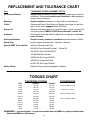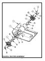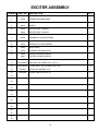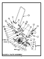
1
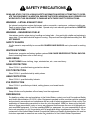
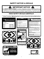
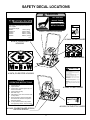
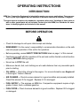
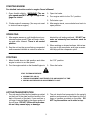
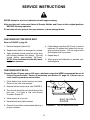
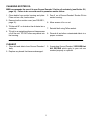
Operator's
Safety
and
Service
Manual
GP4000
GP5500
It is the OWNER'S RESPONSIBILITY to communicate information on the
SAFE USE and OPERATION of this machine to the operators!
MBW INC.
250 HARTFORD ROAD P.O. BOX 440
SLINGER, WI 53086-0440
PHONE: (262) 644-5234 FAX (262) 644-5169
MBW CORPORATE INTERNET ADDRESS
E-MAIL: [email protected]
L1454/05.08 D
MBW Inc 2003
Printed in U.S.A.
IN ENGLAND:
MBW (UK) LIMITED
Units 2 & 3 Cochrane Street
Bolton BL3 6BN, England
Phone: 01204 387784 FAX: 01204 387797
WEB SITE: www.mbw.com
TABLE OF CONTENTS
SAFETY PRECAUTIONS . . . . . . . . . . . . . . . . . . . . . . . . . . . . . . . . . . . . . . . . . . . . . . . . . . .
1
SAFETY NOTICE & DECALS . . . . . . . . . . . . . . . . . . . . . . . . . . . . . . . . . . . . . . . . . . . . . . . .
2
SAFETY DECAL LOCATIONS . . . . . . . . . . . . . . . . . . . . . . . . . . . . . . . . . . . . . . . . . . . . . . .
3
WARRANTY . . . . . . . . . . . . . . . . . . . . . . . . . . . . . . . . . . . . . . . . . . . . . . . . . . . . . . . . . . . . . .
4
MBW WAREHOUSE LOCATIONS . . . . . . . . . . . . . . . . . . . . . . . . . . . . . . . . . . . . . . . . . . .
5
SPECIFICATIONS . . . . . . . . . . . . . . . . . . . . . . . . . . . . . . . . . . . . . . . . . . . . . . . . . . . . . . . . .
6
SERIAL NUMBER LOCATION . . . . . . . . . . . . . . . . . . . . . . . . . . . . . . . . . . . . . . . . . . . . . . .
7
PARTS ORDERING PROCEDURE . . . . . . . . . . . . . . . . . . . . . . . . . . . . . . . . . . . . . . . . . . .
7
OPERATING INSTRUCTIONS . . . . . . . . . . . . . . . . . . . . . . . . . . . . . . . . . . . . . . . . . . . . . . .
8
SERVICE INSTRUCTIONS . . . . . . . . . . . . . . . . . . . . . . . . . . . . . . . . . . . . . . . . . . . . . . . . . . 10
DISASSEMBLY INSTRUCTIONS . . . . . . . . . . . . . . . . . . . . . . . . . . . . . . . . . . . . . . . . . . . . . 12
ASSEMBLY INSTRUCTIONS . . . . . . . . . . . . . . . . . . . . . . . . . . . . . . . . . . . . . . . . . . . . . . . . 14
REPLACEMENT AND TOLERANCE CHART . . . . . . . . . . . . . . . . . . . . . . . . . . . . . . . . . . 16
TORQUE CHART . . . . . . . . . . . . . . . . . . . . . . . . . . . . . . . . . . . . . . . . . . . . . . . . . . . . . . . . . . 16
EXCITER ASSEMBLY . . . . . . . . . . . . . . . . . . . . . . . . . . . . . . . . . . . . . . . . . . . . . . . . . . . . . . 18
PLATE ASSEMBLY . . . . . . . . . . . . . . . . . . . . . . . . . . . . . . . . . . . . . . . . . . . . . . . . . . . . . . . . 20
HONDA ENGINE ASSEMBLY - GP4000 . . . . . . . . . . . . . . . . . . . . . . . . . . . . . . . . . . . . . 22
ROBIN ENGINE ASSEMBLY - GP5500 . . . . . . . . . . . . . . . . . . . . . . . . . . . . . . . . . . . . . . 23
HONDA ENGINE ASSEMBLY - GP5500 . . . . . . . . . . . . . . . . . . . . . . . . . . . . . . . . . . . . . 24
YANMAR ENGINE ASSEMBLY - GP5500 . . . . . . . . . . . . . . . . . . . . . . . . . . . . . . . . . . . . 25
ROLL CAGE ASSEMBLY . . . . . . . . . . . . . . . . . . . . . . . . . . . . . . . . . . . . . . . . . . . . . . . . . . . 26
i
This page intentionally left blank
ii
SAFETY PRECAUTIONS
READ AND STUDY THE FOLLOWING SAFETY INFORMATION BEFORE ATTEMPTING TO OPERĆ
ATE THIS EQUIPMENT. IN ADDITION, ENSURE THAT EVERY INDIVIDUAL WHO OPERATES OR
WORKS WITH THIS EQUIPMENT IS FAMILIAR WITH THESE SAFETY PRECAUTIONS.
WARNING – LETHAL EXHAUST GAS!
An internal combustion engine discharges carbon monoxide, a poisonous, odorless invisible gas.
Death or serious illness may result if inhaled. Operate only in an area with good ventilation, NEVER IN
A CONFINED AREA!
WARNING – DANGEROUS FUELS!
Use extreme caution when storing, handling and using fuels - they are highly volatile and explosive in
vapor state. Do not add fuel while engine is running. Stop and cool the engine before adding fuel. DO
NOT SMOKE!
SAFETY GUARDS
It is the owner's responsibility to ensure ALL GUARDS AND SHIELDS are in place and in working
order.
IGNITION SYSTEMS
Breakerless, magneto and battery ignition systems CAN CAUSE SEVERE ELECTRICAL SHOCKS.
Avoid contacting these units or their wiring.
SAFE DRESS
DO NOT WEAR loose clothing, rings, wristwatches, etc., near machinery.
NOISE PROTECTION
Wear O.S.H.A. specified hearing protection devices.
FOOT PROTECTION
Wear O.S.H.A. specified steel tip safety shoes.
HEAD PROTECTION
Wear O.S.H.A. specified safety helmets.
EYE PROTECTION
Wear O.S.H.A. specified eye shields, safety glasses, and sweat bands.
OPERATOR
Keep children and bystanders off and away from the equipment.
REFERENCES
For details on safety rules and regulations in the United States, contact your local Occupational Safety
and Health Administration (O.S.H.A.) office. Equipment operated in other countries must be operated
and serviced in accordance and compliance with any and all safety requirements of that country.The
publication of these safety precautions is done for your information. MBW Inc. does not by the publiĆ
cation of these precautions, imply or in any way represent that these are the sum of all dangers preĆ
sent near MBW equipment. If you are operating MBW Inc. equipment, it is your responsibility to insure
that such operation is in full accordance with all applicable safety requirements and codes. All reĆ
quirements of the United States Federal Occupational Safety and Healthy Administration Act must be
met when operated in areas that are under the jurisdiction of that United States Department.
1
SAFETY NOTICE & DECALS
IMPORTANT NOTICE
The SAFETY ALERT SYMBOL" is used to call attention to items or operations that may
be dangerous to those operating or working with this equipment. The symbol can be
found throughout the manual and on the unit itself. Please read these warnings carefully.
READ SAFETY DECALS CAREFULLY
Carefully read and follow all safety decals. Keep them in good condition. If decals become damaged, replace as
required. If repainting, REPLACE ALL decals. Decal Kits are available from authorized MBW Distributors.
PLATES
OPERATING INSTRUCTIONS
WARNING
1.
2.
3.
When lifting, use handle bars located at
base of plate.
Approximate weight:
AP2000:
175 lbs. (80 kg)
GP3000Ć15:
215 lbs. (98kg)
GP3000:
250 lbs. (114kg)
GP4000:
239 lbs. (108 kg)
GP5500:
282 lbs. (128 kg)
13478
#13478, EXCITER HOUSING
4.
5.
6.
7.
8.
Check engine oil.
Open fuel valve.
Choke engine. A warm engine may not
need to be choked.
Open throttle part way.
Pull starter rope.
After starting: open choke, return throttle to
idle position.
During operation, when excessive kickback
is noticed, maximum compaction has been
reached.
To stop: Return throttle to idle position, use
engine stop switch, close fuel valve.
13482
#13482, BELTGUARD / DECK
WARNING
CAUTION
Read the Operating Instructions before
operating this piece of equipment.
Keep unauthorized and untrained
people away from this equipment.
ROTATING & MOVING PARTS! Make
sure all guards and safety devices are in
place.
DO NOT RUN this machine in an enĆ
closed area. The engine produces carĆ
bon monoxide, a POISONOUS GAS.
Wear approved hearing protection, foot
protection, eye protection and head
protection.
SHUT OFF the engine before servicing,
cleaning or adding fuel.
Failure to comply could result in seriĆ
ous bodily injury.
#13483, ON BELTGUARD
ROTATING PARTS
Keep hands away!
#12878, ON EXCITER HOUSING
CAUTION
#13484, ON BELTGUARD
HOT SURFACE
DO NOT TOUCH
#01064, ON BELTGUARD
SURFACE CHAUDE
NE PAS TOUCHER
THROTTLE
01069
RUN
12878
#01069, THROTTLE LEVER
#09311, EXCITER HOUSING
2
SAFETY DECAL LOCATIONS
CAUTION
HOT SURFACE
DO NOT TOUCH
WARNING
When lifting, use handle bars located at
base of plate.
Approximate weight:
AP2000:
175 lbs. (80 kg)
GP3000Ć15:
215 lbs. (98kg)
GP3000:
250 lbs. (114kg)
GP4000:
239 lbs. (108 kg)
GP5500:
282 lbs. (128 kg)
SURFACE CHAUDE
NE PAS TOUCHER
WARNING
#09311, EXCITER HOUSING
ROTATING PARTS
Keep hands away!
13478
#13484, ON BELTGUARD
#13478, ON EXCITER
HOUSING
#01064, ON BELTGUARD
CAUTION
12878
Read the Operating Instructions before operating
this piece of equipment.
#12878, ON EXCITER HOUSING
Keep unauthorized and untrained people away
from this equipment.
ROTATING & MOVING PARTS! Make sure all
guards and safety devices are in place.
DO NOT RUN this machine in an enclosed area.
The engine produces carbon monoxide, a POIĆ
SONOUS GAS.
Wear approved hearing protection, foot protection,
eye protection and head protection.
PLATES
OPERATING INSTRUCTIONS
SHUT OFF the engine before servicing, cleaning or
adding fuel.
Failure to comply could result in serious bodily
injury.
1. Check engine oil.
2. Open fuel valve.
3. Choke engine. A warm engine may not
need to be choked.
4. Open throttle part way.
5. Pull starter rope.
6. After starting: open choke, return throttle
to idle position.
7. During operation, when excessive kickĆ
back is noticed, maximum compaction
has been reached.
8. To stop: Return throttle to idle position,
use engine stop switch, close fuel valve.
#13483, ON BELTGUARD
01069
RUN
THROTTLE
13482
#01069, ON THROTTLE LEVER
#13482, ON BELTGUARD GP5500,
ON DECK GP4000
3
WARRANTY
WARRANTY
THIS IS YOUR WARRANTY - PLEASE READ AND SAVE
1. MBW Inc., Slinger Wisconsin, warrants each new machine against defects in material and workmanship
under normal use and service for a period of six (6) months. This warranty commences the first day the
machine is sold, assigned to a rental fleet, or otherwise put to first use.
2. The obligation under this warranty is limited to the replacement or repair of parts and/or machine at MBW
Inc. factory branches or at authorized MBW Inc. Distributors.
3. Machines altered or modified without MBW Inc. written consent voids this warranty. Misuse, negligence,
accidents or the operation of machines in any way other than recommended by MBW Inc. will void this
warranty. This warranty shall not apply to machines repaired by other than MBW Inc. factory branches or
authorized MBW Inc. Distributors.
4. This warranty includes labor on all MBW Inc. products. Labor must be performed at an authorized MBW
Inc. Distributor.
5. The cost of transportation and other expenses connected therewith are not covered by this warranty.
6. Written authorization for the return of merchandise under warranty must be obtained from MBW Inc.,
Slinger, Wisconsin. In England: MBW (UK) LIMITED, Bradley Fold Trading Estate Unit 6, Radcliffe Moor
Road, Bolton BL2 6RT.
7. MBW Inc. reserves the right to inspect and render final decision on each warranty case.
8. MBW Inc. reserves the right to improve or make product changes without incurring any obligation to
update, refit, or install the same on machines previously sold.
9. MBW Inc. is not responsible for any liability or damage or injury directly or indirectly from design, material or
operation of its products.
10. Warranty card must be returned to MBW Inc., P.O. Box 440, Slinger, Wisconsin 53086-0440, within 10 days
after purchase, assignment to a rental fleet, or first use. In England: MBW (UK) LIMITED, Bradley Fold
Trading Estate Unit 6, Radcliffe Moor Road, Bolton BL2 6RT. Failure to return warranty card as specified
renders the warranty null and void.
11. Requests for warranty must be submitted in writing within 30 days after machine failure to MBW Inc., P.O.
Box 440, Slinger, Wisconsin 53086-0440. In England: MBW (UK) LIMITED, Bradley Fold Trading Estate
Unit 6, Radcliffe Moor Road, Bolton BL2 6RT.
12. THE FOREGOING WARRANTY IS EXPRESSLY IN LIEU OF ALL OTHER WARRANTIES, EXPRESSED OR
IMPLIED, INCLUDING THE WARRANTIES OF MERCHANTABILITY AND FITNESS FOR USE, AND OF ALL
OTHER OBLIGATION OR LIABILITIES ON OUR PART, AND WE NEITHER ASSUME NOR AUTHORIZE ANY
OTHER PERSON TO ASSUME FOR US ANY OTHER LIABILITY OR WARRANTY IN CONNECTION WITH
THE SALE OR SERVICE OF ANY OF OUR PRODUCTS. LIKEWISE, THIS WARRANTY SHALL NOT APPLY
WITH RESPECT TO ENGINES, MOTORS AND OTHER COMPONENT PARTS PRODUCED BY OTHER
MANUFACTURERS AND USED ON MBW PRODUCTS, BUT SUCH ITEMS SHALL HAVE SUCH
WARRANTIES AS MAY BE PROVIDED BY THE MANUFACTURER THEREOF.
MBW INC.
250 HARTFORD ROAD P.O. BOX 440
SLINGER, WI 53086-0440
PHONE: (262) 644-5234 FAX (262) 644-5169
MBW CORPORATE INTERNET ADDRESS
E-MAIL: [email protected]
IN ENGLAND:
MBW (UK) LIMITED
Units 2 & 3 Cochrane Street
Bolton BL3 6BN, England
Phone: 01204 387784 FAX: 01204 387797
4
WEB SITE: www.mbw.com
MBW WAREHOUSE LOCATIONS
is at your service
MBW Inc. has established a network of reputable Distributors with trained mechanics and full facilities
for maintenance and rebuilding, and to carry an adequate parts stock in all areas of the country. Their
sales engineers are available for professional consultation. If you cannot locate an MBW Inc. Distributor
in your area, contact one of our Sales Branches or MBW Inc. The locations and phone numbers of the
Sales Branches are listed below.
Remember - you own the best. If repairs are needed use only MBW Inc. parts purchased from
Authorized MBW Inc. Distributors.
Sales Branches:
1. MBW Inc.
250 Hartford Rd.
P.O. Box 440
Slinger, WI 53086Ć0440
Phone: (262) 644Ć5234
FAX: (262) 644-5169
2 . MBW (UK) LIMITED
Units 2 & 3 Cochrane Street
Bolton BL3 6BN, England
Phone: 01204 387784
FAX: 01204 387797
E-MAIL ON THE WORLD WIDE WEB [email protected]
WEB SITE ON THE INTERNET
www.mbw.com
1
Great Britain
2
5
SPECIFICATIONS
GP4000
GP5500
UNITS
GP4000H
GP5500H
GP5500R
GP5500Y
Operating Weight
lbs (kg)
224 (102)
275 (125)
273 (124)
287 (130)
Plate Size WxL
in
(cm)
21 X 25
(53 X 64)
23 X24
(58 X 61)
23 X 24
(58 X 61)
23 X 24
(58 x 61)
Compaction Force
lb (kg)
4200 (1905)
5800 (2610)
5800 (2610)
5800 (2610)
Exciter Speed
vpm
4700
4700
4700
4700
Compaction Depth
in (cm)
18 (47)
20 (51)
20 (51)
20 (51)
Travel Speed (Fwd, Rev)
ft/min (m/min)
130 (38)
130 (38)
130 (38)
130 (38)
Operating Noise Level1
dBA @ operator's ear
902-983
902-983
902-983
902-983
Compaction Area
sqft/h (sqm/h)
13650 (1268)
14950 (1450)
14950 (1450)
14950 (1450)
rpm
3400
3400
3400
3400
rpm
1200
1200
1200
1200
Honda GX160
Honda GX270
Robin EX27
Yanmar Diesel
L60E-D
5.5 (4.1)
8 (6)
8 (6)
6 (4.5)
Normal Operating Engine
Speed4
Engine Idling Speed5
Engine Model
Power Rating @ Normal Operating
Speed
hp (kW)
1. Noise levels are based on operating conditions. Background noise will increase noise levels.
2. Unit operating on loose gravel surface material.
3. Unit operating on highly compacted coarse gravel surface material. Hearing protection is recommended and may be
required by law. It is the users responsibility to assess the noise level at the operation site and determine whether hearĆ
ing protection is required.
4. Normal motor operating speed is factory preset. If this needs adjustment contact your nearest MBW Sales Branch, or
MBW Inc.
5. Motor idle speed is factory preset and adjustment should not be required. If the unit needs adjustment refer to the enĆ
gine owner's manual.
6
SERIAL NUMBER LOCATION
1. The serial number decal is located on top of
the engine deck, behind the engine.
STAMPED LOCATION
EXCITER HOUSING
2. The serial number is also stamped on the
side of the exciter housing.
(Write model number in box)
(Write serial number in box)
GP4000 LOCATION
The units Year of Manufacture can be determined by
the serial number. Contact your nearest Sales
Branch or MBW Inc. for this information.
GP5500 LOCATION
PARTS ORDERING PROCEDURE
The Warranty is stated in this book on page NO TAG. Failure to return Warranty Registration Card renders the
Warranty null and void.
An Owner's Manual" for the engine is also furnished. Engine parts may be ordered from any authorized dealer.
Refer to the engine Owner's Manual" for exploded views and part identifications.
PARTS ORDERING:
MBW Inc. parts are available worldwide and must be ordered through your local MBW Inc. Distributor. If you canĆ
not locate an MBW Inc. Distributor in your area, refer to page NO TAG of this manual to locate the MBW Inc.
Sales Branch nearest you and call for assistance.
ALWAYS INCLUDE:
1.
2.
3.
4.
5.
Model and Serial Number of machine when ordering MBW Parts.
Model and Serial Number of engine when ordering Engine Parts.
Item Part Number, Description, and Quantity.
Company Name, Address, Zip Code, and Purchase Order Number.
Preferred method of shipping.
REMEMBER - you own the best. If repairs are needed use only MBW Inc. parts purchased from
Authorized MBW Inc. Distributors.
7
OPERATING INSTRUCTIONS
INTRODUCTION
MBW Inc. Compaction Equipment is intended for use in very severe applications. They are powĆ
ered by four cycle engines and are available in different sizes and a selection of engines.
This parts manual contains only standard or standard option parts. Variations of these parts as
well as other special parts are not included. Contact your local MBW, Inc. Distributor for assisĆ
tance in identifying parts not included in this manual.
BEFORE OPERATION
Check for damage to unit upon initial receipt and startup.
REMEMBER! It is the owner's responsibility to communicate information on the safe
use and proper operation of this unit to the operators.
Before operating, review SAFETY PRECAUTIONS listed on page 1 of this manual.
Familiarize yourself with the operation of the unit and confirm that all controls function
properly BEFORE starting engine.
Know how to STOP the unit.
Make sure hands, feet, and clothing are at a safe distance from any moveable parts
prior to starting.
OIL LEVEL - Check the oil level in the engine. For more information see Engine oil
in the engine Owner's Manual".
AIR CLEANER - Check to ensure element is in good condition and properly installed.
Clean filter element if it's clogged. Replace it if it's damaged.
FUEL SUPPLY - The engines on MBW Inc. Compaction equipment require a high
grade of clean, fresh, unleaded gasoline.
FUEL FILTER - Check to ensure element is in good condition. Replace it if it's clogged
or damaged.
8
STARTING ENGINE
For detailed instructions refer to engine Owner's Manual.
1. Open throttle slightly. WARNING!! The enĆ
gine speed must NOT be high enough to enĆ
gage the clutch!
3. Open fuel valve.
4. Turn engine switch to the On" position.
5. Pull starter rope.
2. Choke engine if necessary. (You may not need
to choke a warm engine.)
6. After engine starts, move choke lever back to
open position.
OPERATING
1. After engine warms up, pull throttle lever to acĆ
celerate engine speed. Plate will begin vibratĆ
ing and move forward. There is no neutral
position.
dicated by soil testing methods. DO NOT opĆ
erate on extremely hard surfaces such as
concrete.
3. When working on sloped surfaces, hitch a towĆ
ing rope to the compactor and have an assisĆ
tant help pull the compactor uphill.
2. Run the unit on the ground being compacted
until excessive kickback is noticed or when inĆ
STOPPING
1. Move throttle lever to idle position and allow
engine to return to an idle speed.
the Off" position.
2. Turn the engine switch on the Honda Engine to
3. Close fuel valve
STOP THE ENGINE BEFORE:
ADDING FUEL OR OIL
LEAVING EQUIPMENT UNATTENDED, FOR ANY AMOUNT OF TIME
MAKING ANY REPAIRS OR ADJUSTMENTS TO UNIT
LIFTING/TRANSPORTATION
1. The unit may be lifted by the handles provided
on the front of the plate and the handle in the
back of the unit on the deck. If your unit has a
roll cage, it may be lifted by the upper section of
the roll cage. DO NOT lift the unit by the hanĆ
dle as it may cause injury or damage.
2. The unit should be transported in the upright
position and secured or tied down by the roll
cage or handles provided on the plate. DO
NOT lay the machine on its sides or top.
9
SERVICE INSTRUCTIONS
NEVER attempt to service or lubricate unit with engine running.
After servicing unit, restore and fasten all Guards, Shields, and Covers to their original positions
BEFORE resuming operation.
Do not drain oil onto ground, into open streams, or down sewage drains.
CHECKING EXCITER DRIVE BELT
Refer to FIGURE 3, page 20.
1. Remove beltguard (item #15).
4. If belt deflects more than 3/8"(9 mm), it must be
tightened. To tighten belt, loosen the four enĆ
gine mounting screws. Pull the engine back
and retighten the four screws.
2. Replace drive belt if it is damaged or cracked.
3. Apply moderate thumb pressure to the drive
belt halfway between the pulleys. The belt
should deflect approximately 3/8"(9mm).
NOTE: If the shockmounts (item #2) move,
apply less pressure.
5. Repeat step 3.
6. When proper belt deflection is reached, reinĆ
stall beltguard.
CHECKING EXCITER OIL
Change Exciter Oil every year or 500 hours, whichever comes first. MBW recommends the use of
its own Ground Pounder Exciter Oil exclusively (see Exciter Oil, page 16). Failure to do so
could result in premature exciter failure.
1. Clean debris from exciter housing and plate.
Place unit on a flat, level surface.
2. Remove bolt on exciter cover (see FIGURE 1).
3. The oil level should be up to the bottom of the
bolt hole. If oil level is low, add Ground
Pounder Exciter Oil.
4. Allow excess oil to run out.
BOLT, OIL DRAIN
EXCITER
5. Reinstall bolt using Teflon sealant.
6. Discard oil and other contaminated debris in a
proper container.
FIGURE 1: OIL PLUG LOCATION
10
CHANGING EXCITER OIL
MBW recommends the use of its own Ground Pounder Exciter oil exclusively (see Exciter Oil,
page 16). Failure to do so could result in premature exciter failure.
1. Clean debris from exciter housing and plate.
Place unit on a flat, level surface.
5. Pour 6 oz. of Ground Pounder Exciter Oil into
exciter housing.
2. Remove bolt on exciter cover (see FIGURE 1,
page 10).
6. Allow excess oil to run out.
3. Tilt the unit 90° on its side so the oil drains into a
container.
7. Reinstall bolt using Teflon sealant.
4. Tilt unit to an upright position and clean excess
oil off the unit. DO NOT allow any debris into
the housing.
8. Discard oil and other contaminated debris in a
proper container.
CLEANUP
1. Clean dirt and debris from Ground Pounder
daily.
3. If repainting Ground Pounder, BE SURE that
ALL DECALS which apply to your unit are
masked properly or replaced.
2. Replace any decals that become damaged.
11
DISASSEMBLY INSTRUCTIONS
CAUTION: Assembly and Disassembly should be performed by a service technician who has been
factory trained on MBW Inc. equipment.
The unit should be clean and free of debris, especially around the exciter housing cover. Steam
cleaning is recommended.
ENGINE REMOVAL
1. Remove beltguard.
3. Remove belt from engine.
2. Remove the four engine mounting screws and
mounting bars.
4. Lift engine off.
EXCITER DISASSEMBLY
Refer to FIGURE 2, page 18.
1. Clean the housing and drain the oil (see
CHANGING EXCITER OIL, page 11).
6. Remove seal (item #8) from cover. (You will
destroy the seal)
2. Remove pulley (item #1) and key (item #8) for
GP4000. Remove the tapered bushing (item
#13) and sheave (item #12) for GP5500. Refer
to FIGURE 3, page 20.
7. Remove retaining ring (item #11) and press
out exciter shaft (item #5) from the cover.
8. Remove retaining ring (item #2) and press out
the bearing (item #9) from the cover.
3. Remove six bolts (item #15) from exciter cover.
9. Remove six bolts (item #15) from exciter cover
on other side.
4. Install two of the bolts you just removed, into
the holes with plugs. Run them in evenly as far
as you can, this will remove the cover and the
exciter shaft assembly.
10. Repeat steps 4 and 5.
11. Remove retaining ring (item #2) and press out
the bearing (item #7) from the cover.
5. Remove cover gasket (item #4).
12
HANDLE DISASSEMBLY
Refer to FIGURE 3, page 20.
1. Remove cotter pins (item #5).
with lockwashers (item #23) from handle
brackets (item #11).
2. Unscrew the hex head cap screws (item #21)
3. Remove the handle.
DECK REMOVAL
Refer to FIGURE 3, page 20.
1. Remove four hex head cap screws (item #20 &
#21) with lockwashers (item #23).
2. Lift deck from housing assy (item #16).
13
ASSEMBLY INSTRUCTIONS
Prior to assembly wash all parts in a suitable cleaner or solvent.
Check moving parts for wear and failure. Refer to REPLACEMENT AND TOLERANCE CHART for
tolerances and replacement cycles.
Replace all seals and gaskets at every overhaul or disassembly.
For torque settings other than those listed, see torque chart.
EXCITER ASSEMBLY
Refer to FIGURE 2, page 17.
1. Press bearing (item #7) into cover (item #10).
Then, install retaining ring (item #2) into posiĆ
tion.
5. Press exciter shaft (item #5) into cover assemĆ
bly. Then, install retaining ring (item #11) into
position.
2. Apply a thin layer of grease to outer flange and
put a new gasket (item #4) in place.
6. Press a new seal (item #8) into cover (item #6).
3. Press this assembly, into the housing assemĆ
bly (item #12). Be sure to place oil drain in
the down position. Then, install the six flange
whiz-lock screws (item #15).
7. Press this assembly, into the housing assemĆ
bly (item #12). Then, install the six flange
whiz-lock screws (item #15).
4. Press bearing (item #9) into cover (item #6).
Then, install retaining ring (item #2) into posiĆ
tion.
8. Install pulley (item #1, fig. 3) and key (item #8,
fig 3) for GP4000. Install the tapered bushing
(item #13, fig 3) and sheave (item #12, fig 3)
for GP5500.
DECK ASSEMBLY
Refer to FIGURE 3, page 19.
1. Install the two hex head cap screws (item #21)
with lockwashers (item #23) into the front
mounts.
2. Install the remaining two hex head cap screws
(item #21) with lockwashers (item #23) into
the rear mounts.
14
HANDLE ASSEMBLY
Refer to FIGURE 3, page 19.
1. Install handle brackets (item #11) onto the
handle.
lockwashers (item #23).
3. Install cotter pins (item #5). Make sure nylon
bushings (items #3 & #4) are in place.
2. Install hex head cap screws (item #21) with
ENGINE ASSEMBLY
1. Place engine on deck.
3. Install the drive belt.
2. Install four engine mounting screws and
mounting bars. DO NOT TIGHTEN
4. Refer to checking exciter drive belt section on
page 10 and do steps 2 thru 6.
15
REPLACEMENT AND TOLERANCE CHART
Part
TOLERANCE OR REPLACEMENT CYCLE
Air Cleaner Element
Replace after 50 hours if engine is operating under good clean air
conditions. Service and replace more frequently if under extremely
dusty or dirty conditions.
Bearings
Replace anytime a Bearing is rough, binding or discolored.
Clutch
Replace the Clutch if the Shoes and Spring show signs of heat damĆ
age or if the Clutch engages below 2000 rpm.
Exciter Oil
Replace once every season or every 500 hours. Use 6 ounces of oil
from the 6Ćpack of MBW #01058 Ground Pounder Exciter Oil.
Hardware
ReĆtorque all bolts after the first eight hours of operation and check
every 25 hours.
Seals and Gaskets
Replace at every overhaul or teardown and when exciter is rebuilt.
Spark Plug
See the engine manufacturer's Operator's Manual.
Special MBW Tools and Kits
#00134 Universal Load Cart
#01058 6ĆPack Ground Pounder
Exciter Oil
#01603 Kit, Decal GP4000/5500
#01629 Test Mat, Rubber
#02484 Kit, Roll Cage GP5500
#07585 Kit, Gasket and Seal
#13907 Kit, Roll Cage GP4000
Safety Decals
Replace if they become damaged or illegible.
TORQUE CHART
TIGHTENING TORQUE
SIZE
10Ć24
10Ć32
1/4Ć20
1/4Ć28
5/16Ć18
5/16Ć24
3/8Ć16
3/8Ć24
7/16Ć14
7/16Ć20
1/2Ć13
1/2Ć20
GRADE 2
32 inĆlb
32 inĆlb
70 inĆlb
85 inĆlb
150 inĆlb
165 inĆlb
260 inĆlb
300 inĆlb
35 ftĆlb
45 ftĆlb
50 ftĆlb
70 ftĆlb
CONVERSIONS
GRADE5
40 inĆlb
32 inĆlb
115 inĆlb
140 inĆlb
250 inĆlb
270 inĆlb
35 ftĆlb
40 ftĆlb
55 ftĆlb
75 ftĆlb
80 ftĆlb
105 ftĆlb
in lbs x 0.083 = ftĆlbs
ft lbs x 12 = inĆlbs
ft lbs x 0.1383 = kgĆm
ft lbs x 1.3558 = Nm
REMEMBER - you own the best. If repairs are needed use only MBW Inc. parts purchased from
Authorized MBW Inc. Distributors.
16
This page intentionally left blank
17
FIGURE 2: EXCITER ASSEMBLY
18
EXCITER ASSEMBLY
ITEM NO
PART NO
DESCRIPTION
QTY
1.
00066
FILTER RETAINER
1
2.
01000
INTERNAL RETAINING RING
2
3.
01072
FILTER
1
4.
06098
GASKET
2
5.
07446
EXCITER SHAFT (GP5500)
1
12822
EXCITER SHAFT (GP4000)
1
6.
07455
FRONT COVER
1
7.
07456
CYLINDRICAL ROLLER BEARING
1
8.
07457
OIL SEAL
1
9.
07458
SPHERICAL ROLLER BEARING
1
10.
07460
REAR COVER
1
11.
07469
EXTERNAL RETAINING RING
2
12.
13856
EXCITER HOUSING (GP4000)
1
13857
EXCITER HOUSING (GP5500)
1
SPIROL PIN, 1/8" x 5/8"
1
13.
F0205SP
14.
F051804HCS
HEX HEAD CAP SCREW, 5/16-18 x 1/2"
5
15.
F051808FWS
FLANGE WHIZ-LOCK SCREW, 5/16-18 x 1"
12
16.
F05BFW
BRASS FLAT WASHER, 5/16"
1
17.
F0618SPP
SOCKET PIPE PLUG, 3/8-18
1
18.
19.
20.
21.
22.
23.
24.
25.
26.
27.
28.
29.
30.
31.
32.
19
FIGURE 3: PLATE ASSEMBLY
20
PLATE ASSEMBLY
ITEM NO
PART NO
DESCRIPTION
QTY
1.*
00003
EXCITER PULLEY
1
2.
01011
SHOCKMOUNT
8
3.
01018
OUTER NYLON BUSHING
2
4.
01019
INNER NYLON BUSHING
2
5.
01056
HAIRPIN
2
6.*
01099
WASHER
1
7.**
01161
KEY, 1/4" x 1/4" x 1Ć1/2"
1
8.*
01283
KEY, 1/4" x 1/4" x 1Ć1/4"
1
9.**
02715
HANDLE SPACER (NOT SHOWN BETWEEN DECK AND SHOCKMOUNTS)
2
10.
02717
HANDLE ASSEMBLY (Includes items 3 & 4)
1
11.
06921
HANDLE BRACKET
2
12.**
07452
TWO GROOVE SHEAVE
1
13.**
07453
SPLIT TAPER BUSHING
1
14.
12637
ENGINE DECK
1
15.
12832
BELTGUARD (GP4000)
1
12879
BELTGUARD (GP5500)
1
13861
EXCITER & PLATE ASSEMBLY (GP4000)
1
13862
EXCITER & PLATE ASSEMBLY (GP5500)
1
16.
17.**
F051808HCS
HEX HEAD CAP SCREW, 5/16-18 x 1"
3
18.*
F051814FWS
FLANGE WHIZ-LOCK SCREW, 5/16-18 x 1Ć3/4"
1
19.
F061607FWS
FLANGE WHIZ-LOCK SCREW, 3/8-16 x 7/8"
3
20.
F081305HCS
HEX HEAD CAP SCREW, 1/2-13 x 5/8"
2
21.
F081306HCS
HEX HEAD CAP SCREW, 1/2-13 x 3/4"
14
22.**
F081310HCS
HEX HEAD CAP SCREW, 1/2-13 x 1Ć1/4"
4
23.
F08LW
LOCKWASHER, 1/2"
16
24.
F08PW
PLAIN WASHER, 1/2"
2
25.
26.
27.
28.
29.
30.
*
PARTS USED ON GP4000 ONLY
** PARTS USED ON GP5500 ONLY
21
4
7
5
9
2
6
8
10
1
3
FIGURE 4: HONDA ENGINE
HONDA ENGINE ASSEMBLY - GP4000
ITEM NO
PART NO
1.
00031
MOUNTING BAR
2
2.
00032
KEY, 3/16" SQUARE x 1Ć5/8" LONG
1
3.
01182
V-BELT, AĆ34
1
4.
01444
ENGINE, HONDA GX160 5.5 hp
1
5.
16105
CENTRIFUGAL CLUTCH (S/N 1151054 and above)
1
05999
CENTRIFUGAL CLUTCH (S/N 1151053 and below)
14993
COUNTERSINK WASHER
6.
DESCRIPTION
QTY
1
7.
F051814HCS HEX HEAD CAP SCREW, 5/16-18 x 1Ć3/4" LONG
4
8.
F052408FSS
FLAT HEAD SET SCREW, 5/16-24 x 1" LONG
1
9.
F05LW
LOCKWASHER, 5/16"
4
10.
F05SW
PLAIN WASHER, 5/16"
4
22
6
2
5
4
7
3
1
10
8
9
FIGURE 5: ROBIN EX27 ENGINE
ROBIN ENGINE ASSEMBLY - GP5500
ITEM NO
PART NO
1.
17440
ENGINE, ROBIN EX27 9 HP
1
2.
05909
SPACER
4
3.
06469
SKYHOOK
1
4.
DESCRIPTION
QTY
F061608FWS FLANGE WHIZ-LOCK SCREW, 3/8-16 X 1"
4
5.
07932
TERMINAL, PIN STYLE FEMALE
1
6.
07877
CASING, LINED THROTTLE WIRE
1
7.
07662
WIRE, THROTTLE
1
8.
06361
KIT, CABLE CLAMP
1
9.
10.
F061614HCS HEX HEAD CAP SCREW, 3/8-16 X 1-3/4"
F0616FN
HEX WHIZ-LOCK NUT, 3/8-16
11.
12.
23
4
4
1
6
3
7
5
9
8
4
2
FIGURE 6: HONDA ENGINE
HONDA ENGINE ASSEMBLY - GP5500
ITEM NO
PART NO
1.
15674
ENGINE, HONDA, GX270 16.5 cu/in (270 cu/cm)
1
2.
05935
V-BELT, AXĆ35
2
3.
06934
DOUBLE GROOVE CENTRIFUGAL CLUTCH
1
4.
12968
MOUNTING BAR
2
5.
14992
COUNTERSINK WASHER
1
6.
DESCRIPTION
QTY
F061614HCS HEX HEAD CAP SCREW, 3/8-16 x 1Ć3/4" LONG
4
7.
F06LW
LOCKWASHER, 3/8"
4
8.
F06SW
PLAIN WASHER, 3/8"
4
9.
F072008FSS
FLAT HEAD SET SCREW, 7/16-20 x 1" LONG
1
10.
11.
12.
24
14
11
2
20
4
1
5
13
12
17
15
19
PTO SIDE
10
16
28
8
21
23
7
16
15
18
9
3
18
FIGURE 7: YANMAR ENGINE
27
24
29
30
26
22
25
SPRING ATTACHES AS SHOWN,
USE THE THIRD HOLES FROM
CENTER PIVOT.
6
GOVERNOR ATTACHED
TO ENGINE
YANMAR ENGINE ASSEMBLY - GP5500
ITEM NO
1.
2.
3.
4.
5.
6.
7.
8.
9.
10.
11.
12.
13.
14.
15.
16.
17.
18.
19.
20.
21.
22.
23.
24.
25.
26.
27.
28.
29.
30.
PART NO
00387
02198
02428
02558
02559
05477
05714
05935
06934
07912
07921
08388
F04LW
F042004HCS
F06LW
F06SW
F0616LN
F061614HCS
F072008SCS
J0021008000
Z11425266051
Z11425266112
Z11425266250
Z11425066200
Z11497066010
Z26476060142
Z26106060202
Z10210067080
Z11425066440
Z26757060002
DESCRIPTION
ENGINE, YANMAR L60E-D 6hp
THROTTLE CONTROL ASM
ENGINE ADAPTOR
MOUNT, THROTTLE
SPACER, 3/4 X 3/8 X 1.2
SWIVEL (included with item 2)
WASHER, PILOT
V-BELT, AX-35
CLUTCH, CENTRIFUGAL DOUBLE GROOVE
WIRE, THROTTLE
CASING
HEX HEAD CAP SCREW, M8 X 80MM LONG
LOCKWASHER, 1/4"
HEX HEAD CAP SCREW, 1/4-20 X 1/2" LONG
LOCKWASHER, 3/8"
PLAIN WASHER, 3/8"
LOCKNUT, 3/8-16
HEX HEAD CAP SCREW, 3/8-16 X 1-3/4" LONG
SOCKET HEAD CAP SCREW, 7/16-20 X 1" LONG
LOCKWASHER, 8MM
LEVER, SPEED CONTROL
BRACKET, ACCELERATOR
SPRING, RETURN
SPRING, SHORT
SPRING, LONG
BOLT, M6 X 14MM LONG
BOLT, M6 X 20MM LONG
BOLT, ADJUSTING
BOLT, ADJUSTING
LOCKNUT, M6
25
QTY
1
1
1
1
2
1
1
2
1
1
1
2
2
2
8
8
4
8
1
2
1
1
1
1
1
1
1
1
1
2
FIGURE 8: ROLL CAGE
ROLL CAGE - GP4000-GP5500
ITEM NO
PART NO
1.
13882
ROLL CAGE (GP4000)
1
02483
ROLL CAGE (GP5500)
1
13907
KIT, GP4000 ROLL CAGE (includes items 1, 3, 4, & 5)
02484
KIT, GP5500 ROLL CAGE (includes items 1, 3, 4, & 5)
2.
3.
F0518FN
DESCRIPTION
QTY
FLANGE WHIZ-LOCK NUT, 5/16-18
9
4.
F051806FWS FLANGE WHIZ-LOCK SCREW 5/16-18 X 3/4" LONG
7
5.
F051808FWS FLANGE WHIZ-LOCK SCREW 5/16-18 X 1" LONG
2
MOUNT ROLL CAGE TO LOCATE HOLE POSITION IN THE BELTGUARD.
MARK POSITION. REMOVE ROLL CAGE AND DRILL TWO 13/32 DIA.
HOLES. REINSTALL ROLL CAGE WITH HARDWARE PROVIDED.
26