1
Robin
Model
G
RGD25
ator
OlRGD3300
1 ISSUE EMD-GO604
1
Section
Title
1.
SPECIFICATIONS
2.
PERFORMANCE
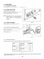
2-1
2-2
2-3
Page
1
.............................................
2
..............................................
2
3
5
Model RGD2500
.........................................
.........................................
Model RGD3300
DC Output.
.............................................
3.
FEATURES ..................................................
6
4.
GENERAL DESCRIPTION OF GENERATOR .......................
7
4- 1
4-2
4-3
5.
External View of Generator .................................
Control Panel ............................................
Location of Serial Number and Specification
Number
CONSTRUCTION
5-1
5-2
5-3
AND FUNCTION
.......................................
SAFETY PRECAUTIONS
7.
RANGE OF APPLICATIONS
8.
MEASURING
9.
10.
10- 1
1 0-2
1 0-3
1 0-4
10-5
15
15
19
22
23
PROCEDURES ....................................
26
FUNCTIONAL
MEMBERS ............................
Voltmeter and Pilot Lamp ..................................
AC Receptacles ..........................................
Circuit Breaker ...........................................
Stator ..................................................
Rotor Assembly ..........................................
Condenser ..............................................
Diode Rectifier ...........................................
DISASSEMBLY
15
....................................
Measuring Instruments
.....................................
AC Output Measuring ......................................
Measuring Insulation Resistance ..............................
CHECKING
9- 1
9-2
9-3
9-4
9-5
9-6
9-7
..............................
............................................
Construction
Function
...............................................
Description of Generator Operation ...........................
6.
8-1
8-2
8-3
.............
7
8
14
AND ASSEMBLY ................................
Preparation and Precautions .................................
Special Tools for Disassembly and Assembly ....................
Disassembly Procedures ....................................
Assembly Procedures ......................................
Checking, Disassembly and Reassembly of the Control Box . . . . . . . . .
26
28
28
30
30
30
31
31
32
32
33
34
34
34
35
43
55
11. TROUBLE
11-1
11-2
11-3
11-4
11-5
Page
Title
Section
SHOOTING
.. ........
No AC Output
...... ......
AC voltage is too high or too low
AC voltage is normal at no-load,
No DC Output . . . . . . . . . . . .
Oil sensor trouble shooting . . .
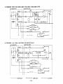
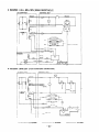
12. WIRING DIAGRAM
....
....
..
but
....
....
...
...
.. .
the
...
...
.........
.........
.........
load cannot
.........
.........
.........
.........
.........
be applied
.........
.........
... ..
.....
.....
....
.....
.....
.
.
.
.
.
.
56
56
57
58
59
60
. . . . . . . . . . . . . . . . . . . . . . . . . . . . . . . . . . . . . . . . . . . 61
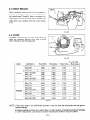
Model
--..
-_-
Type
- _-
,.-
-._
-.-.
_ ___
.--
Withrn
-.
Air-cooled,
_-
___
4 cycle,
rpm
50 Hr:
60 H7:
4.8 PS/3600
.--
rpm
5.0 PS/3000
Oil
rpm
l-
.-
5.5 PS/3600
.-
rpm
-_
Starter
-_
0.9 liters
_ .-__
and Optional
.._
.50 H7: 1.18 liters/hour
60 Hz: 1.30 liters/hour
- ----_.
-
Recoil
.-.-.._
._
7.8 liters (2.1 U.S. gal.)
.._
0.93 liters/hour
1 .lO liters/hour
-
-_-
LxWxH
-.__
265cc (16.17 cuin.)
_._----_
--..
Dimensions
_
DY27D
._
___.--
-. .
230 cc (I 4.04 cuin.)
_.
-_.
.,
Diesel engine
--__-
Diesel Light
Ratio
.-
10%
bY23D
.
4.3 PS/3000
-
.-__
- ..-
(IOOW)
-_-_
Condenser Type
. .-
__.
.--
Phase
1.0
-_
.
2-Pole, Single
12V-8.3A
..--
._--
Field, Self-Exciting,
RGD3300
. .-_.
-__-
--_
-..
Fuel Consumption
(at Ratc!tl Ol.rtpllt)
Revolving
.-_.
- --_
I Type
.-
___
--
Voltage Regulator
..Voltage Regulation
--
j
u
- ..~.
Brushless,
Power Factor
-_.
DC Output
u
c
RGD2500
-_-
-.--
.
-.
-
.-.
Electric
___
Starter
_.
-
536 x 400 x 458 mm (21 .I x 15.8 x 18.0 in.)
. .-.709 x 400 x 458 mm (27.9 x 15.8 x 18.0 in.)
Specifications
-._
are subject
_
._--
to change without
notice.
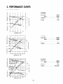
PERFORMANCE CURVES
MODEL RGD2500
RGD2500
Output
53
Max.
Rated
52
51
Frequency
50
Voltage.
49
...............
..............
.................
..................
2200W
2000W
50Hz
220v
230
4
2
220
s
2
210
0
2
6
8
4
CURRENT
(A)---+
10
RGD2500
Output
Max.
Rated
i
2k
Frequency
Voltage.
4
0
t
2
4
6
8
CURRENT
(A) +
51
4
49
50
.................
..................
2000W
50Hz
240V
RGD2500
Output
1
230
Frequency
A
Voltage
Y
220
0
4
8
12
16
CURRENT
(A)---)
Max.
Rated
I
4 2k
i
E
..............
2200W
10
52
53
z
...............
20
-2-
...............
..............
.................
................
2200W
2000W
50Hz
11 OV!22OV
RGD2500
Output
Max.
Rated
Frequency
Voltage
O
4
8
CURRENT
12
IA)--,
16
20
...............
..............
.................
................
2500W
2300W
60Hz
11 OV!22OV
24
RGD2500
63
Output
62
Rated
61
60
Frequency
59
A
Max.
Voltage
...............
..............
.................
...................
2500W
2300W
60Hz
120v
130
120
110
I
0
4
8
12
16
CURRENT
IA) ---)
20
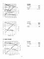
2-2 MODEL RGD3300
RGD3300
Output
Max.
Rated
Frequency.
-2k
A
Voltage
230
t
>
220
0
2
4
6
CURRENT
8
IA) +
10
12
14
-3-
...............
..............
................
...................
3000W
2700W
50Hz
220v
t
N
I
RGD3300
53
s
ze
52
5
UJ
r
LL
50
1
51
49
- 2k
250
4
5
g
;r
-I
0
>
Output
‘3k
I
-I lk
240
Max.
Rated
Frequency
..............
.................
Voltage.
t
...............
..................
3000W
2700W
50Hz
240V
2
c
2
E
5
0
230
0
2
4
6
CURRENT
8
10
(A) --)
12
14
RGD3300
52
I
51
Output
-r3k
50
Max.
Rated
49
Frequency.
- 2k
230
220
Voltage
...............
..............
................
................
3000W
2700W
50Hz
11 OVi22OV
t
z
i
3
k
=
0
210
-1k
120
110
I
100
0
4
8
12
CURREhlT
16
(At +
20
24
28
JO
RGD3300
Output
i , /’
Rated
Frequency
2
0
w
z
Voltage.
230
220
t
210
2
g
120
2
110
g
>
100
0
4
8
12
CURRENT
Max.
16
(Ai+
20
24
8 1
28
32
0
-4-
...............
..............
.................
...............
3300W
3000W
60Hz
1 lOV:22OV
A
63.
RGD3300
1
Output
...............
Max.
Rated
Frequency
Voltage.
..............
.................
...............
3300
3000
60Hz
12OVi24OV
‘i
CURRENT
(A) +
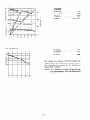
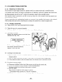
2-3 DC OUTPUT
t
20
18
5
16
g
14
2
12
DC Voltage
................
12v
DC Ampere
................
6.3A
DC Output
................
1oow
The voltage curve shown in the left indicates the
characteristic of DC output when charging a batter?.
The voltage may be decreased b!- 20% when the resistance load is applied.
NOTE:
0
2
4
CURRENT
6
IA) -
8
10
-5-
It is possible to use both DC and AC outputs simultaneously
up to the rated output
in to tat.
3. FEATURES
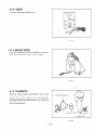
3-1 BRUSHLESS ALTERNATOR
Netvly developed brushless alternator sliminates troublesome brush maintenance.
3-2 EASY STARTING
Light pull recoil starter accompanied Lvith automatic decompression system makes the new RGD series
gensrators ev2n easier in starting than gasoline engine generators.
3-3 QUIET OPERATION
The new RGD seriss generator provides qui2t operation by means of:
0 The superb design of intake-eshaust system.
Direct injection combustion sl-stem.
0 .A large super silent muffler.
0 An efficient 10~~noise air cleansr.
l
3-4 ECONOMICAL
PERFORMANCE
On top of ~~211known diesel economy. the air-cooled Robin dies21engine f2aturss dirzct fu2! injection
and spscial dssign refinements for extra fu21 efficiens>-.
3-5 OIL SENSOR
Ths OIL SESSOR automaticall)- shuts the 2ngin2 off whenever th2 oil level falls down below a safe 12v21
prsv2nting engine seizur2.
3-6 COMPACT, LIGHT WEIGHT
The combination of ne\vl>- devslop2d brushless alternator and air-cool2d sing12 cl-linder Robin di2sel
engine enables the n2w RGD ssrirs generators to be \-er>-compact in size and light in weight.
3-7 RELIABLE
PERFORMANCE
WITH MINIMAL
MAINTENANCE
0 A brushlsss alternator eliminates troublesome brush maintsnancs.
0 A drip-proof alternator design.
l A trouble free condsnser voltags regulator.
l
.A fus212sscircuit breaksr.
l
A dust-proof dual element air cleaner.
The OIL SESSOR automaticall!- shuts ths rsngine off wh2n2ver the oil
level prsv2nting sngine szizurs.
l
3-8 LONG-LIFE
l
l
level
falls down belokv a safe
DURABILITY
Compact and smooth running air-cool2d Robin dirssl 2ngin2 lasts much longr than th2 gasoline
2ngin2 of th2 Sam2 sizs.
Trouble-fr22 brushless altsrnator 1%.ith2ondzns2r t)-ps voltags regulator Lvorks all the year round
without any maintenace work.
-6-
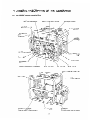
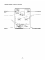
4. GENERAL DESCRIPTION OF TH
E GENERATOR
4-l
EXTERNAL VIEW of GENERATOR
NO-FUSE
ROCKER
BREAKER
COVER
AC VOLTMETER
KEY
SWITCH
(Electric
starter
as option)
type
FUEL
INJECTION
-STOP
I
EARTH
(GROUND)
TERMINAL
\
I
FUEL
Ltvtn
FILTER
o\IL FILTER
FUEL
FUEL
TANK
COCK
& TANK
CAP
MUFFLER
FUEL
STARTING
IFlcvrrlc
__.._F
OIL CiAUbf=
MOTOR
starter
type
as OptIOn)
-7-
GAUGE
-, . . . -.
(Electric
sti wtef
type
as optiol
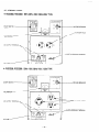
4-2 CONTROL PANEL
l
RGD2500, RGD3300:
START
luptlonl
50Hz-220V, 24OV. 60Hz-220V TYPE
SWITCH
NO-FUSE
BREAKER
AAC RECEP
DC OUTPUT
TERMINAL
EARTH
!GROUNDl
TERMINAL
DC FUSE
. RGD2500, RGD3300:
START
IOPtionl
50Hz-11OV. 60Hz-llOV,
120V TYPE
SWITCH
DC OUTPUT
TERMINAL
NO-FUSE
\
II,-
9
m’
AC
RECEPTA
EARTH
DC FUSE/
-8-
BREAKER
(GROUNDI
TERMINAL
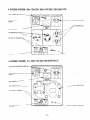
. RGD2500, RGD3300:
FULL
START
(Option)
POWER
SWITCH
50Hz-llOV/220V,
60Hz-llOV/220V,
12OV/24OV TYPE
-
NO-FUSE
SWITCH
BREAKER
AC RECEPTACLE
VOLTMETER/
DC OUTPUT
;:d
TERMINAL
\
‘EARTH
DC FUSE!
. RGD2500, RGD3300:
VOLTAGE
START
(ODtion
CHANGEOVER
U.K., 50Hz-llOV/220V
SWITCH
:GROUNDl
TERMlhAL
[BS RECEPTACLE]
z
NO-FUSE
SWITCH
I
BREAKER
VOLTMETER/
1lOV
22OV RECEPTACLE-
DC OUTPUT
RECEPTACLE
>
TERMINAL
\
? ’
DC FUSE!
-9-
EARTH
IGROUND)
TERMINAL
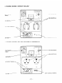
. RGD2500:
U.S.A., 60Hz-120V [NEMA
RECEPTACLE]
NO-FUSE
PILOT
BREAKER
LAMP
12OV RECEP
RTH
. RGD3300:
FULL
START
(Option)
POWER
U.S.A., 60Hz-120V/240V
[NEMA
TERMINAL
RECEPTACLE]
SWITCH
SWITCH
-NO-FUSE
-.,a
~
PILOT
IGROUND!
BREAKER
I
0
0,
120V
RECEPTACLE
LAMP
EARTH
- 10-
IGROUNDi
TERMINAL
. RGD2500, RGD3300:
START
(Option)
GERMANY, 50Hz-220V
NO-FUSE
SWITCH
220V
VOLTMETER
DC OUTPUT
BREAKER
RECEPTACLE
/
TERMINAL
\
EARTH
DC FUSE/
. RGD2500, RGD3300:
START
(OptIonI
TERMINAL
50Hz-220V [WITH SPECIAL RECEPTACLE]
NO-FUSE
SWITCH
T
VOLTMETER/
DC OUTPUT
(GROUND)
220V
BREAKER
RECEPTACLE
TERMINAL
\
EARTH
DC FUSE ------
- 11-
IGROUND)
TERMINAL
. RGD2500, RGD3300:
START
(OptIoni
SWITZERLAND,
50Hz-220V
NO-FUSE
SWITCH
220v
VOLTMETER
BREAKER
RECEPTACLE
y
DC OUTPUT
TERMINAL
\
DC FUSE
l
EARTH
!
RGD2500, RGD3300:
!GROUND!
TERMINAL
FRANCE, 50Hz-220V
NO-FUSE
VOLTMETER
BREAKER
220V
RECEPTACLE
iGROUND
TERMlnAL
y
DC OUTPUT
TERMI’UAL
\
DC FUSE
y
’
- 12-
EARTH
8 RGD2500, RGD3300:
START
IOptbon)
AUSTRALIA,
50Hz240V
SWITCH
NO-FUSE
240V
BREAKER
RECEPTACLE
VOLTMETER
DC OUTPUT
TERMINAL
RTH
DC FUSE
- 13-
(GROUNDI
TERMINAL
4-3 LOCATION of SERIAL NUMBER and SPECIFICATION
NUMBER
Serial number and specification number arc stamped on the L-ABEL (MODEL
T.UlE)
stuck on the end
cover.
NOTE:
Always specify these numbers when inquiring
to get correct parts and accurate service.
about
the generator
or ordering
spare parts in order
SERIAL
- 14-
NUMBER
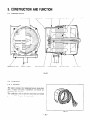
5. CONSTRUCTION
AND FUNCTION
5- 1 CONSTRUCTION
STATOR
GENERATOR
BASE
MOUNT
BOLT
END
RUBBER
BALL
COVER
REAR
BEARING
STATOR
COVER
THROUGH
BOLT
COMPLETE
SUPPORT
RING
Fig. 5- 1
5-2 FUNCTION
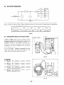
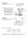
5-2- 1 STATOR
The stator consists of a laminated silicon steel sheet
core. a main coil and a condenser coil Lvhich are
wound in the core slots.
The condenser coil excites the rotor field coil \vhich
gensrates XC voltage in the main coil.
Fig. 5-2
- 15-
ROTOR
FRONT
COMPLE
COVER
TE
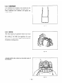
5-2-Z
CUNDENSEK
Two condensers are installed in the control box and
are connected to the condenser coil of the stator.
These condensers and condenser coil regulate the
output voltage.
Fig. 5-3
5-2-3
ROTOR
The rotor consists of a laminated silicon steel sheet
core and a field coil which is wound over the core.
DC current in the field coil magnetizes the steel
sheet core. Two permanent magnets are provided for
the primary exciting action.
Fig. 5-4
A diode rectifier and a resistor are mounted inside of
the insulator.
I
DIODE
RECTIFIER
& SURGE
Fig. 5-5
- 16-
ABSORBER
5-2-4
(1)
FUSE
The 10 ampere DC fuse mounted on the control panel protects whole DC circuit from getting damage by overload or short circuit.
(2)
0
Q
The 15 ampere DC fuse in the control box protects the diode rectifier from getting damage
by reverse connection to the battery.
(Electric start model)
Fig. 5-6
5-2-5
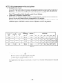
NO-FUSE BREAKER
The no-fuse breaker protects the generator from gettmg damage by overloading or short circuit in the appliancc.
RATING
GENERATOR
SPECIFICATION
50Hz-IlOV
50Hz-220V
50Hz-240V
-
50Hz-1 lOVf22OV
RGD3300
20A
25A
IOA
12A
10A
12A
12Ax2
27A
20A
60Hz-120V
-
60Hz-1 lOV!22OV
-
20A
I
27A
14Ax
lOAx
lOAx
I
BREAKER
RGD2500
lOAx
60Hz-1 IOV
60Hz-120V/240V
OF NO-FUSE
I
2
14Ax2
Table 5- 7
Fig. 5-7
-
17-
7
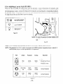
5-2-6
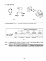
RECEPTACLE and AC PLUG (STD. SPEC.)
These are used for taking AC output po\ver from the generator. X total of four kinds of receptacles, each
varying in rated voltage and current from another. are used. Each model has at least one receptacle to deliver
the rated generator output. As many AC plugs as the receptacles. each matching the corresponding receptacle,
r 2 sho\vs the rated current for each receptacle. Be careful not to use the receptacles and
are provided. Table 3AC plugs beyond the specified limits to prcvsnt burning.
1
from
-u
-q
,a.3
*
+$
w’
I
!
!
two receptacles
up to 15 amperes
up to 30 amperes
(See Caution.)
Table 5- 2
Caution:
To connect the appliance to locking receptacle, insert
the plug into the receptacle and turn it clockwise to
lock.
Fig. 5-8
NOTE:
If your generator
has receptacles peculiar
to your country,
Table 5-2 does not apply.
NOTE:
The generator for U.S. A. market is equipped with NEMA standard receptacles shown in table 5-3.
Use the proper plug for connecting appliance to the generator.
I
Style
’
Ampere
125V
20A
Receptacle
Description
AC plug
NEMA
NEMA
5-20R
5-2OP
,
GFCI
’
(Ground Fault Circuit
Interrupter
I
Receptacle,
NEMA
NEMA
20A
Ll4-20R
L14-20P
125V
NEMA
30A
L5-30
125V
250V
/
NEMA
L5-3OP
Table 5 - 3
- 18-
duplex
Locking
Receptacle
Locking
Receptacle
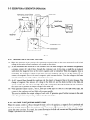
5-3 DESCRIPTION
of GENERATOR
PERMANENT
FOR INITIAL
MAGNET
EXCITATION
FIELD
STATOR
1%
‘d
7
1
NI
I
s
i’
t
F
RESISTOR
------J
i@k
------I
I
/
/
MAIN
r----7
COIL
COIL
ROTOR
r------
L-
OPERATION
/
II
I’
I’
I’
i’
I
I
I
I
APPLIANCE
I
I
I
i
DIODE
CONDENSER
COIL
CONDENSER
Fig. 5-9
5-3- 1 GENERATION
of NO-LOAD VOLTAGE
(1,
When the generator starts running. the permanent magnet built-in to the rotor generates 3 to 6V of AC
voltage in the main coil and condenser coil wound on the stator.
(2)
As two condensers are connected to the condenser coil. the small voltage at the condenser coil generates
a minute current @ which flows through th-e condenser coil. At this time, a small flux is produced
with which the magnetic force at the rotor’s magnetic pole is intensified. When this magnetic force is
intensified. the respective voltages in the main coil and condenser coil rise up. As the current @ increases, the magnetic flux at the rotor’s magnetic pole increases further. Thus the voltages at the main
coil and condenser coil keep rising by repeating this process.
(3)
As AC current flows through the condenser coil. the density of magnetic flux in the rotor changes. This
change of magnetic flux induces AC voltage in the field coil. and the diode rectifier in the field coil
circuit rectifies this AC voltage into DC. Thus a DC current flows through the field coil and magnetizes
the rotor core to generate an output voltage in the main coil.
(4)
\-C‘hengenerator speed reaches 2700 to 1800 rpm (5OHz type) or 3000 to 3300 rpm (60Hz type), the
current in the condenser coil and field coil increases rapidly.
This acts to stabilize the output voltage of each coils. If generator speed further increases to the rated
value. the generator output voltage uill reach to the rated value.
5-3-2
VOLTAGE
FLUCTUATIONS
UNDER LOAD
When the output current @ flows through the main coil to the appliance, a magnetic flux is produced and
serves to increase current @ in the condenser coil. When current 3 increases, the density of magnetic flux
across the rotor core rises. As a result. the current flowing in the field coil increases and the generator output
voltage is prevented from decreasing.
- 19-
5-3-3
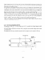
FULL POWER SWITCH (Dual Voltage Type)
The full power switch is provided for the dual voltage type to take out the full rated po\ver from one receptacle in each voltage.
120124OV
r---l~or11o/22ov)
-
MC,
240V
lor 22OV)
Fig. 5- 10
MC:
Fig. 5-l 1
1 Rec. 1
I
Switch
Position
i
LOWER VOLTAGE
RECEPTACLE
HIGHER
VOLTAGE
RECEPTACLE
11ov
i
I
1
Rated output
No output
can be taken.
I&
240V
(22OV)
110.22ov
120°~40v
I
MC,
’
Half of rated
output
I
Table 5- 4
Fig. 5-12
- 20 -
Rated output
Inside the generator are t\vo sets of main coils. Each main coil outputs half the rated power at the lower voltage (1 1OV or 1ZOVI. These main coils are wound to be in the Sam2phase. The full power s\vit& reconnects
these main coils in parallel or in s2ries.
Fig. 5-10 sho\vs a circuit diagram. 1Vh2n the full power switch is set for single lower voltage indication (1 1OV
or 1ZOV). the switch position is as indicated by th2 lower solid line in the diagram. Fig. 5-l 1 is a simplified
representation of this circuit. show-ing the two main coils connected in parallel. In this case. the higher voltage i7ZO\- or Z4OVi at Rec. 3 cannot be taken out. Rec. 2 tor
- the lower voltage can output up to the rated
power (up to 30.1 if the rated current is over 30-A). and Rec. 1 can output up to a total of 15A.
\Vhen the full poiver s\vitch is set for double voltage indication ( 1 1OV 3201’ or 12OV ‘24OV), the switch
position is as indicated by the upper dotted line in Fig. 5-l 0. Fig. 5- 12 is a simplified representation of this
circuit. showing the two main coils connected in series. In this case. power can be taken simultaneously
from the receptacles for the both voltages. Rec. 3 for th? higher voltage can output up to the rated power.
but Rec. 1 and Rec. 3 for the lower voltage can output only up to half the rated power each.
Table 5-4 is a summary of the above ssplanation. Select the propsr output I-oltags by full power witch in
accordance with the appliance to be used.
5-3-4
VOLTAGE
CHANGEOVER
SWITCH
The
gensrator of 50Hz 1101’ L3OV dual voltage type for U.K. is provided with voltage changeover switch
instead of full pow2r switch.
The output voltage is sel2cted from 11OV and ‘1OV bx turning this switch and both voltages cannot be taken
out simultaneously.
The middle point of the main coil shall be grounded \vhen the changeol-er sn-itch is turned to 11OV side.
11OV RECEPTACLE
RECEPTACLE
Fig. 5-73
-21-
6. SAFETY PRECAUTIONS
1. Use extreme caution near fuel. A constant danger of explosion or fire exists.
Do not fill the fuel tank while the engins is running. Do not smoke or use open flame near the fuel tank.
Be careful not to spill fuel when refueling. If spilt. wipe it and let dry before starting the engine.
2. Do not place inflammable materials near the generator.
Be careful not to put fuel. matchss. gunpoa-dsr. oily cloth. straw. and an)- other intlammables near the
generator.
3. Do not operate the generator in a room, cave or tunnel. Always operate in a well-ventilated area.
Otherwise the engine may overheat and also. the poisonous carbon monoxide contained in th2 exhaust
gases will endanger human li\-2s. K2ep thz gen2rator at 12ast 1 m (4 f2et) a\va)- from structures or facilities during use.
4. Operate the generator on a level surface.
If the gsnerator is tilt2d or movzd during us2. thers is a danger of fuel spillage and a chance that the generator may tip over.
5. Do not operate with wet hands or in the rain.
Severe electric shock ma?- occur. If ths gsnerator is wet b!- rain or snow. wipe it and thoroughly dry it
before starting.
Don’t pour water o\-2r the gensrator dir2ctll- nor leash it with wat2r.
If the generator is xv-etwith water. th2 insulations ii-ill b2 adv2rsely affectsd and may cause current leakage and electric shock.
6. Do not connect the generator to the commercial power lines.
This may cause a short-circuit or damage to the gsn2rator. Us2 a transf2r s\vitch for connecting with indoor wiring.
NOTE:
The parts numbers
Table 6- 1.
of the transfer
switches and of the plastic box to store them are as shown in
Part Name
Part No.
365-45604-08
Transfer
Switch
367-45605-08
Transfer
Switch
Transfer
Switch
340-45606-08
’
367-43008-08
348-43009-08
Plastic Box
’
8 O’ty
1
i
’
I
I
1
1
1
1
Plastic Box
’
1
1
a
Phase
Allowable
15A
’
30A
1
60A
1
30A
1
Current
’
I
60A
Table 6- 7
7. Use a fuse of the correct capacity. (DC output)
If the generator rpm is incr2as2d excessiv2lq- in th2 overload condition bk- using an over rated fuse. th2
generator may be burnt.
CAUTION: If the fuse is burnt out or the circuit breaker tripped off as a result of using an electrical
appliance, the cause can be an overload or a short-circuit. In such a case, stop operation immediately and
carefully check the electrical appliance and AC plugs for faulty wiring.
- 22 -
7. RANGE OF APPLICATIONS
Generally. the power rating of an electrical appliance indicates the amount of Lvork that can be done by it.
The electric power required for operating an electrical appliance is not always equal to the output wattage of
the appliance. The electrical appliances generall)- have a lab4 showing their rated voltage. frequency. and
power consumption (input wattage). The po\ver consumption of an electrical appliance is the power necessary for using it. \Vhen using a generator for operating an electrical appliance. the power factor and starting
wattage must be taken into consideration.
In order to determine the right sizs generator. it is nxessary to add the total kvattage of all appliances to be
connected to the unit.
Refer to the followings to calcurate the po\ver consumption! of each appliance or equipment by its t!‘pe.
(1)
Incandescent lamp, heater, etc. with a power factor of 1.0
Total power consumption must be equal to or less than the rated output of the generator.
Example: X rated 3OOO\Vgsnsrator can turn thirt). lOON’ incandescent lamps on.
(2)
Fluorescent lamps, mercury lamps, etc. with a smaller power factor
Select a generator kvith a rated output equivalent to 1.2 to 2 times of the power consumption of the
load.
Example: A 4OON’mercury lamp requires 6OOL to -0OK power source to be turned on.
A rated 3OOO\Vgensrator can power four or fivs 4OOK mercur)- lamps.
NOTE
1: If a power factor correction capacitor is not applied to the mercury lamp or fluorescent
the more power shall be required to drive those lamps.
A rated 3000W generator can drive one or two 400W mercury lamps without power
correction capacitors.
lamp,
factor
NOTE 2: Nominal wattage of the fluorescent lamp generally indicates the output wattage of the lamp.
Therefore, if the fluorescent lamp has no special indication as to the power consumption,
efficiency should be taken into account as explained in ltem (51 on the following page.
(3)
Motor driven tools and light electrical appliances
Generally- the starting Lvattage of motor driven tools and light electrical appliances are 1.2 to 2 times
larger than their running Lvattagc.
Example: A ratsd 2501V electric drill requires a -tOO\Vgenerator to start it.
(4)
Initially loaded motor driven appliances such as water pumps, compressors, etc.
Thsss appliances require the large starting wattage kvhish is 3 to 5 times of running lvattage.
Example: .A rated 900\V compressor requires a 45OON’generator to drive it.
NOTE
1: Motor-driven
appliances require the aforementioned
generator output only at the starting.
Once their motors are started, the appliances consume about 1.2 to 2 times their rated power
consumption
so that the excess power generated by the generator can be used for other electrica / appliances.
NOTE 2: Motor-driven
appliances mentioned in ltems (3) and (4) vary in their required motor starting
power depending on the kind of motor and start-up load. lf it is difficult
to determine the
optimum generator capacity, select a generator with a larger capacity.
- 23 -
(5)
Appliances without any indication as to power consumption
Some appliances have no indication as to poH-er consumption: but instead the work load ioutput) is
indicated. In such a case. po\ver consumption is to be worked out according to the numerical formula
mentioned below.
(Output of electrical appliance)
= (Poner consumption 1
iEfficienq)
Efficiencies of some electrical appliances are as follo~vs:
The smaller the motor. the lower
Sin&.-phase motor . . . . . . . . . . . . _ . 0.6 - 0.75 1.
Three-phase motor
. . . . . _ . . . . . . . 0.65 - 0.9 z
the efficienq-.
Fluorescent lamp . . . _ . . . _ . . . . . 0.7 - 0.8
Example 1: A -IO%-tluorsscent lamp means that its luminous output is 4OR’. Its efficiency is 0.7 and
accordin&-. power consumption will be 40 + 0.7 = 57iV. A%explained in Item (2). multiply this power consumption value of 5-W by 1.2 - 3 and you will pet the figure of the
necessaq- capacit), of a generator. In other words. a generator with a rated output of 1OOOK
capacit>- can light nine to fourteen 40X fluorescent lamps.
Example 2: Generally- speaking. a 400X motor means that its Lvork load is 4001V. Efficiency of this
motor is 0.7 and power consumption n-ill be 400 + 0.7 = 5’0\5‘. N-hen this motor is used
for a motor-driven tool. the capacity of the generator should be multipled by 1.1 to 3 and
57OW as explained in the Item (3).
r
MODEL
I
Frequency
lncandesent
lamp, heater,
Fluorescent
lamp, mercury
Motor-driven
tool,
Water pump,
compressor,
60 Hz
50 Hz
60 Hz
2ooow
22OOW
2700W
3000121
approx.
1400w
approx.
approx.
15OOW
18OOW
approx.
12oow
approx.
approx.
approx.
approx.
50Hz
etc.
lamp, etc.
general-purpose
etc.
motor,
etc.
i
RGD3300
RGD2500
600W
Table 7- 1
- 24 -
’
13oow
650W
approx.
21 oow
16OOW
approx.
18OOW
approx.
approx.
800W
9oow
I
NOTES:
Wiring between generator
and electrical
appliances
1. Allowable current of cable
Use a cable with an allowable current that is larger than the rated input current of the load (electrical
appliance). If the input current is larger than the allowable current of the cable used, the cable will become excessively heated and deteriorate the insulation, possibly burning it out.
Table 7-2 shows cables and their allowable currents for your reference.
2.
Voltage drop in long electric extension cords
When a long wire is used to connect an appliance with the generator, a certain amount of voltage drop
occurs in the wire which lessens effective voltage available to the appliance.
The table below has been prepared to illustrate the approximate
voltage loss when an extension cord
of 300 feet (approx. 100 meters) is used to connect an appliance or tool to the generator.
!
I
Nominal cross
section
A.W.G.
Gauge No.
Allowable
current
: No. of
strandshtrand
Reststance
dia.
I
A
No. mm
mm’
!
UO.
0.75
’
18
7
16
12
50 0.18
14
17
37026
i
23
45 0 32
’
35
70 032
1
1.27
2.0
3.5
5.5
/
12 - 10
110-d
I
I
Current
Amp.
I
-0. 100 T
2.477
1 486
30018
0952
c.517
0332
1
1
I
1A
3A
5A
25
8V
12.5V
1 5v
5v
11;
3v
-
j 15v
I
-
:’
1L’
!
8A!lOA
-
-
12A
15A
-
-
7.5v
, 12v
15v
j18V
5V
8V
iov
i 12v
I
15v
5v
6.5V
7.5v
2 5v
2v
1 4v
2.5V
!
’ 3.5V
1 4V
0”
G
.
B
r
s
5V
Table 7-2
1-oltage drop indicates as \’ = -
1
100
‘- R b. 1 ‘\ i
R means resistance ( S2 100 m I on the above table.
I Illt!dIlS eltxtri< iurrent through the \i iI-2 ( A 1.
I; means the length of the v, ire ( ITI 1.
The length of the \\iire indicate> round length.
it means t\vi<e the length from generator to electrical
tools.
- 25 -
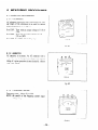
8. MEASURING PROCEDURES
8-l
MEASURING
8-l-l
INSTRUMENTS
VOLTMETER
AC voltmeter is necessary. The approximate .4C voltage ranges of the voltmeters to be used for various
types
of generators are as follows:
0 to 15OV: Type with an output \-oltag of 1 10 or
13ov
0 to 300V: Type with an output voltage of “0.
230. or Z4OV
0 to 15OV. 0 to 300\-: Dual voltage type
I
FOR
AC
I
Fig. 8- 1
8-1-2
AMMETER
AC ammeter is necessary. An AC ammeter with a
range that can be changed according to the current
rating of a given generator is most desirable. (.\bout
1OA. 30‘4. 100-A\)
FOR AC
Fig. 8-2
8-l-3
r
FREQUENCY METER
Frequency range: About 35 to 65Hz
NOTE:
Be careful of the frequency
voltage range.
meter’s
input
Fig. 8-3
- 26 -
8-l-4
TESTER
Used for measuring resistance. etc.
Fig. 8-4
8-l-5
MEGGER TESTER
Used for measuring generator insulation resistance.
Select one lvith testing x-oltage rang of 5001-.
I
I
Fig. 8-5
8-1-6
TACHOMETER
There are various types of tashometsrs. ~~1~ as contactless type. contact tl.ps. and strobe tk-ps. The
contxt t!-pe can be ussd onl>- n-hen the generator
and engine ha\e been disassembled. The contactless
type is recommended.
CCN’J~ACTLESS
TYPE
,
I
STROBE
Fig. 8-6
-27
-
TYPE
8-2
AC OUTPUT MEASURING
LJ
Fig. 8-7
Use a cirsurt like the one shown in Fip. 8-- for msasurinp XC output. A hot plate or lamp with a power factor of 1.O may be used as a load. Adjust the load and rpm. and check that the vo1tas-eranpe is as specified in
Table 8- 1 at the rated amperage and rated rpm.
Rated voltage
’
Voltagerange
11ov
107-
I
120v
220v
117 - 130v
119v
215-238
I
240V
235 - 260
Table 8.; 1
8-3
MEASURING
INSULATION
RESISTANCE
VEGGER
TESTER
Connect a megger tester to one of recsptacls output
terminals and th2 ground terminal. then measure the
insulation resistance. An insulation rtzsistance of 1
me_gohm or more is normal. (Th2 original insulation
resistance at the time oi shipment from the factory
is 10 megohms or mars.)
If it is 12~s than 1 megohm. disassemble the 92nerator and measure th2 insulation resistanx of the
stator. rotor and control panel individuall!..
I
I
1
Fig. 8-8
. STATOR
(1) Measure th2 insulation resistanc2
BLUE lead and the core.
(2 j Measure the insulation resistance
WHITE lead and the corz.
(3) Measure the insulation resistanc2
YELLOW lead and the core.
(4) Measure the insulation resistaxe
BL-KK lead and ths core.
I
between
b2tw2en
betwe2n
b2t\\-een
J
1
Fig. k-9
- 28 -
. ROTOR
Measure the insulation across one of the soldered
terminals of the rotor and the core.
Fig. 8-70
. CONTROL PANEL
Measure the insulation resistances between the live
parts and the grounded parts.
Fig. 8- 11
Any part where the insulation resistance is less than 1MS1 has faulty insulation. and may cause electric leakage and electric shock.
Replace the faulty part.
- 29 -
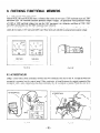
9. CHECKING FUNCTIONAL
MEMBERS
9-1 VOLTMETER and PILOT LAMP
Models RGD2500 and RGD3300 have a voltmeter that comes in two types: 15OV maximum type and 300V
maximum type. The voltmeter indicates generator output voltages. The generators with a generated voltage
of 11OV or 1ZOV and dual voltage type use the 15OV maximum type voltmeter; and those of 31OV. 2301!
and 24O\r specifications use the 300V maximum type voltmeter.
Generator for U.S.A. employs a pilot lamp. The lamp lights when a voltage is generated. The pilot lamp also
comes in two t>-pes: 135\’ t)-pe and 34OV type. These types are selected to suit generator output voltage.
300V
(22OV.
WAX.
23OV.
15OV MAX.
240V1
(1 lOV,
12OV)
Fig. 9-7A
Fig. 9- 78
9-2 AC RECEPTACLES
Usins a circuit tester. check continuity. between the two terminals at the rear of the AC receptacles while the
receptacle is mounted on the control panel. &-hen continuity is found between the output terminals of the
receptacle with a wire connected across these terminals. the AC receptacle is normal. \Yhen the wire is removed and no continuity is found between these terminals. the receptacles are also normal.
AC RECEPTACLE
-
Fig. 9-2A
Fig. 9-2B
- 30 -
9-3 CIRCUIT BREAKER
1 CIRCUIT
Check continuity between each of two terminals at
the rear of the circuit breaker Lvhile it is mounted on
the control panel. ?;ormall]-. there is continuity between each of the two when the circuit breaker is on
while there is no continuity when the circuit breaker
is off.
Fig. 9-3
9-4 STATOR
Disengage connectors on the wires from stator and
check the resistance between Lvires with a circuit
tester referring to the following table.
Fig. 9-4
(R x In +10x)
Brown-White
Blue-Skyblue
50Hz-11 OV
0.86E
0.86G
0.16_0,
0.86fi
0.16Q
2.IL?
0.91,0,
0.16,0,
2.lQ
Specifications
Model
50Hz-220V
0.869
,
50Hz-240V
0.9IQ
:
50Hz-IlOV/220V
RGD2500
’
0.86R
!
0.16.0,
0.66C
0.66Q
0.12R
60Hz-120V
0.669
0.66,0,
0.129
, Black-Orange 1
!
2.lR
i
1.9-c2
0.66fi
0.12,
1.9,c2
0.669
0.12,0,
1.9*0,
50Hz-11 OV
0.64,0_
0.64R
0.14,0_
1.9n
50Hz-220V
0.64fi
0.64Q
0.14_0_
I.99
0.77fi
0.14a
1.90
0.649
0.14n
I .9fi
0.660
1
50Hz-240V
i
0.77_0,
50Hz-1 IOV: 220V
,
60Hz-IIOV
I
0.649
!
!
0.449-
0.440
0.44,nl
60Hz-ll0V~220V
0.44R 0.44_0, -
0.449
0.1 l,o,
60Hz-120V
0.449
0.44_0,
0.11~
60Hz-220V
‘240V
I
I
I
---z---l
0.66C
60Hz-110V/220V
i
0.862
60Hz-1IOV
60Hz-120V!240V
RGD3300
j
I
! Yellow-Yellow
0.1 l,r!
I.6C
0.1 IR
1.60
1.6R
i
I
I
I
1.6n
Table 9- 1
NOTE:
If the circuit tester is not sufficientlly
accurate, it may not show the values given and may give erroneous readings.
Erroneous readings will also occur when there is a wide variation of resistance among coil windings
or when measurement is performed at ambient temperatures different from 20°C (68”FJ.
-31-
9-5 ROTOR ASSEMBLY
1) Using the circuit tester, measure the resistance
of the field coil.
Table 9- 2
NOTE
I: Measure the resistance of each coil winding while the diode and each resistor are
disconnected with their solder removed.
;
NOTE 2: If the circuit tester is not sufficiently
accurate, it may not show the values given
and may give erroneous readings.
Erroneous reading will also occur when
there is a wide variation
of resistance
among coil windings or when measurement is performed
at ambient temperatures different from 2O’C 168°F).
i
Fig. 9-5
9-6 CONDENSER
H If an instrument (QC-meter or C-meter) for measuring capacity of condender is available. check
the capacity of condenser. (Se? Fig. 9-6. I
COUDEUSEil
Fig. 9-6
n
NORMAL CAPACITY OF CONDENSER
I
NODEL
RGD2500
(g
CAPACITY
ig
I
:
1OpF
IOpF
RGD3300
1OpF
I
l&IF
Table 9-3
n
If such an instrument is unavailabl?. the condenser can be checked by replacing with a new one. If the generator performs good with new condenser. the cause of trouble is defect in original condenser.
- 32 -
9-7 DIODE RECTIFIER
DIODE
RECTIFIER
Yellow
Grey
Red
Red
-
Yellow
Yellow
0
II
Yellow
I]
Gw
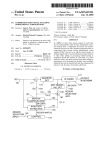
CIRCUIT
Fig. 9-7
TESTER
Fig. 9-8
Circuit inside of the diode rectifiers is as shown in Fig. 9- 7. Check continuity between each terminal by using
a circuit tester as shown in Fig. 9-8. The rectifier is normal when continuity is as follows:
Apply black 0
Yellow
!
needle of the circuit tester
Yellow
1
Yellow
Apply red @ needle
of the circuit tester
! Yellow
1
No continuity
’ Red
!
Continuity
1
,
Grey
’
I
:
Red
No continuity
,
I
’
No continuity
Grey
Continuity
Continuity
Continuity
I
-
F
No continuity
’
I
-
No continuity
1
1
No continuity
Table 9- 4
NOTE
1: In checking the diode, direction
teristics of the diode and battery
of connection is contrary to the ordinary
incorporated in the tester.
case because of charac-
NOTE 2: “Continuity”
means forward direction characteristics of the diode, and different from short circuit
condition
(in which a pointer of the tester goes out of its normal scale), shows resistance to some
extent. When results of the checking indicates failure even in one section, replace with a new one.
- 33 -
10. DISASSEMBLY AND ASSEMBLY
10-I
PREPARATION
and PRECAUTIONS
1) Be sure to memorize the location of individual parts when disassembling the generator so that the generator can be reassembed corrwtl!-. Tie tags noted with the necessar>-information to facilitate easier and
smoother reassembly-.
3) For more convenience. divide the parts into several groups and store them in boxes.
3) To prevent bolts and nuts from being misplaced or installed incorrectly. place them temporarily back at
their original position.
4) Handle disassembled parts with car?: clean them before reass?mbl>-using a neutral cleaning fluid.
5) Us2 all disassembly assembly tools properly. and use the proper tool for each specific job.
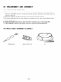
10-2 SPECIAL TOOLS for DISASSEMBLY and ASSEMBLY
ROTOR PULLER
REAR COVER PULLER
- 34 -
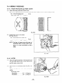
10-3 DISASSEMBLY
jtep
1
PROCEDURES
‘art to remove
Fuel Tank
Tool
Remarks
Description
Draining tank of fuel
before disassembly is unnecessary.
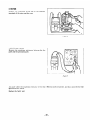
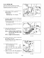
(1) Close fuel cock.
(2) Loosen the nut and remove fuel cock
from the bracket.
Turn the fuel cock body by 90 degrees
to remove. (Fig. 10-l)
14 mm spanner
I
(3 j Remove the two bolts which join the
fuel filter to the control box.
(See Fig. 10-3.)
10 mm spanner
(4) Remove the fuel pipe which connects
Plier
fuel filter and fuel injection pump.
Loosen the clamp using pliers and pull
out the fuel pipe from the fuel filter.
(See Fig. 10-3:)
Fig. lo- 1
Fig. 70-3
Fig. 10-2
- 35 -
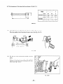
Step
1
Part to remove
Fuel Tank
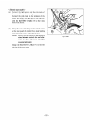
(5) Remove fuel return pipe which connects
the fuel injection nozzle and the bottom
of fuel tank.
Loosen the clamp and pull out the fuel
return pipe from the fuel injection
nozzle. (Fig. 10-4)
Take care of spilt fuel
from the fuel pipe.
Fig. 70-4
Control Box
Plier
i
10 mm spanner or
box spanner
(6) Loosen the four bolts and remove fuel
tank from frame. (See Fig. 10-j.)
2
Tool
Remarks
Description
Fig. 10-5
(1) Remove control box from frame by removing the three bolts joining the control box to frame and side plate.
(See Fig. 10-6.)
(2) Put the control box with control panel
d0Lv-n.
Wire harness is still connected.
Put a waste cloth under / 10 mm spanner
: the control panel to protect it.
(3) Remove the ground wire (green!yellow)
from the bottom of control box.
(4) Pull the bushing out from the control
box. (See Fig. 10-Y.)
Fig. IO-6
Fig. 10-7
- 36 -
10 mm spanner or
box spanner
Remarks
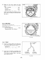
tep
Part to remove
Description
2
Control Box
(5) Pull the wire harnessout from the control box.
Disengagethe connectorsto separate
the control box. (SeeFig. 10-8.)
Tool
1
‘.
I\
Fig. 108
I
3
Pipe Frame
10 mm spanneror
box spanner
(1) Removesideplate from frame.
66bolt.. . . . . . . . .2pcs.
(2) Removetank bracket from frame.
6@bolt . . . . . . . . . .2pcs.
B@BOLT
(3) Removestoppersfrom enginebaseof
frame.
6Obolt.. . . . . . . . .4pcs.
10 mm spanner
(4) Removethe four nuts which join the
mount rubbersto the engine.
12 mm spanner
(5) Removethe two bolts which join the
rear coverto the generatorbase.
(SeeFig. 10-9.)
8Obolt . . . . . . . . . .2pcs.
12 mm spanner
. . . . . . 4pcs.
80 NUT
. . 2~s.
78
STOPPER. . . .
Fig. 109
-
37
-
I
. Zpcs.
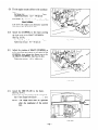
Step
3
Part to remove
Pipe Frame
Description
Remarks
(6) Lift up the engine and alternator assembly using a chain-block. and dismount it
from frame. (Fig. 10-10)
Tool
i
Fig. 10-10
(7) Remove generator base from frame.
8~ nut . , . . . . . . . . 1 pee.
(8) Remove mount rubbers from frame.
(See Fig. 10-l l.j
MOUNT
i 12 mm spanner
12 mm spanner
2pcs.
8c NUT
GENERATOR
r
BASE
RUBBER
2pcs.
Fig. 10-l 1
- 38 -
Step ) Part to remove !
Description
I
(1) Remove end cover from rear cover.
Rear 'Over
' . . (See Fig. lo-l'.)
1
I
I
I
I
6obolt..
:. . . . _ . .4pcs.
1 (2) Remove through bolt from rotor shaft.
Xppl>- a socket wrench on the head of
through bolt and hit the wrench handle
I
with a hammer counterclockwise to
loosen. (See Fig. 10-13.)
Remarks
I
-1--
I
~~~
10 mm spanner or
I
I
I
I
1 RGDZSOO: 12 mm
1 RGD3300: 14 mm
Box wrench
I
i
I (3) Remove the four bolts which join the
rear cover to the front cover.
I
I
I
I
I
I
i
(1) Take off the rear cover.
Use the special tool “REAR COVER
PULLER” to remove the rear cover.
(See Fig. 10-14.)
a. Insert the two bolts of the special
tool into the thread holes of the
rear cover.
,
b. Apply the center bolt of the special
tool to the center hole of the rotor
shaft.
I
c. Tighten the center bolt to pull out
the rear cover. (See Fig. 10-15.)
Tool
I
I
r Insert the two bolts sufficiently and evenly-, or
! the thread holes may be
1 damaged at removing.
I
i
Fig. lo- 72
Fig. lo- 13
6;
Fig. 70-74
Fig. lo-15
BOLT
.
2~s.
Step
Part to remove
4
Description
Remarks
In case that “REAR COVER PULLER” is unavailable. remove the rear
cover by the following instructions:
Rear Cover
I
a. Insert the through bolt into the rotor
shaft and tighten lightly.
b. Hit on the boss at the top of the rear
cover and two legs evenI)- with a plastic
hammer to remove. (Fig. lo- 16j
I
I
1
1
F/g. lo-16
I
I
’ Stator
(1) Remove the four bolts which join the
stator to rear cover. (See Fig. 10-17.)
I
(2) Insert a small hook into the hole inside
of the support ring and pull it out.
(See Fig. 10-18.)
l
If a small hook is unavailable, remove
the stator by the following procedure:
a. Hold the rear cover and stator assembly open side down.
b. Place a cushion under the stator to
protect it when dropped.
c. Hit on the bearing housing of rear
cover with a wooden block.
60 BOLT
. .
69 SPRING
WASHER
/
Ilk
I
Plastic hammer
I
1
I
5
Tool
.
4 PCS.
4pcs.
6r, WASHER
4 PCS.
- 40 -
I
I
’
I
I
’ Be careful not to give a
damage to the staror
l winding.
’
10 mm box wrench
!
Step
Part to remove
Description
Stator
5
Remarks
Tool
(3) Pull out the wires from rear cover.
(See Fig. 10-19.)
I
STATOR
60 BOLT
.
.
4 PCS.
Fig. IO- 19
,
6
. Rotor
I
I
I (1) Insert the rotor-puller shaft into the
rotor and tighten the rotor-puller bolt
until the rotor comes loose.
(See Fig. 10-1-O.)
If the special tool (rotor-puller) is unavailable, take the folloCng instructions
to remove the rotor:
Lightly strike the rotor core with
a plastic hammer in many directions
and pull out the rotor from engine
shaft. (See Fig. 10-21.)
1 Rotor puller
1 RGDXOO: 14mm
RGD3300: 17 mm
Spanner
1 Take utmost care not to 1
strike on the rotor wind- j
ing or plastic insulator or ,
1 Plastic hammer
permanent magnets.
Fig. lo-21
Fig. 70-20
-41-
Step ’ Part to remove
I
7
1 Front cover
and Front
j Protector
Description
Remarks
Tool
I
’ (1) Remove the four bolts which join the
front cover to the engine.
gobolt..
. . . . . . . .4pcs.
12 mm spanner
( (2) Remove front protector from front
Cover. (See Fig. 10-Z.)
8 mm spanner or
I screw driver (+)
I
1
1
/
Fig. lo-22
- 42 -
I
10-4 ASSEMBLY PROCEDURES
10-4-l
(1)
FRONT PROTECTOR and FRONT COVER
Attach the front protector to front cover.
The louvers of the front protector project into the inside of front cover as shown in Fig. 10-23.
5# x 10 mm Tapping screw . . . . . 4 PCS.
Tightening torque: 35 - 55 kg-cm
Fig. IO-23
(2)
Install front cover to the engine.
(See Fig. 10-24.)
8$ x 20 mm bolt and washer assy
. . . . . . . . . . . . . . . . . . . . . . . . . 4 PCS.
Tightening torque: 120 - 140 kg-cm
NOTE:
The size of faucet joint and pitch of
mounting
holes of front cover is different by models RGD2500 and RGD
3300.
Fig. IO-24
10-4-2
ROTOR
(1)
Clean the tapered portion of driving shaft and
the matching tapered hole of rotor shaft of oil
and dirt using a waste cloth.
(2)
Attach rotor to the driving shaft. (See Fig. lo25.)
Tighten through bolt with washer and spring
washer.
Tightening torque:
RGDXOO.. . . . . . . 115 - 135 kg-cm
RGD3300. . _ . . . . . 330 - 250 kg-cm
Fig. lo-25
10-4-3
Hookmg holes for remown
support -1ng
STATOR and REAR COVER
(1)
Set the stator on the jig.
Match the grooves of the stator with the
grooves of the jig.
(2)
Attach the support ring around the stator setting the open ends of the ring to the position
of stator leads.
Check that the hooking holes are placed at the
flat sides of the stator. (See Fig. 10-X.)
D~mx~on
Grooves
of stator
leads
of stator
STATOR
SUPPORT
(3)
(4)
(5)
Insert four guide bolts into the bolt holes of
the rear cover and mount it on the stator
matching the guide bolts with the grooves of
the stator.
Tighten the guide bolts tentatively.
Grooves
RING
JIG
o‘ ,‘g
Fig. lo-26
BOARD
Take the stator leads out from the windo\\- of
the rear cover.
\
Put a board on the rear cover and press it using
a pressing machine.
If a pressing machine is unavailable. tap around
the board on the rear cover even&- with a plastic hammer to press fit the rear cover over the
stator. (See Fig. 10-Y.)
CAUTION: Take care of the rear cover to be
pressed in upright position.
Fig. lo-27
(6)
Join the stator to rear cover with four bolts.
washers and spring washers. (See Fig. 10-28.)
60 bolt . . . . . . . _ . . . . . . . . . _ 4 PCS.
60 washer . . . . . . . . . . . . . . . . . _ . 4 pcs.
6Q spring washer . . . . . . . . . . . . . . 4 pcs.
Tightening torque: 80 - 100 kg-cm
NOTE:
Tighten
steps.
60 BOLT
4 DCS.
II----6~ SPRlhG
d//
m
oM-
60 WASHER
four bolts evenly taking several
I
Fig. lo-28
- 44 -
WASHER
.4pcs.
4 PCS.
l
The dimensions of the stator bolts are shown in Table 1O-l.
I
I
Model
RGD2500
[(mm)
1
I
i
85
I (inch) I
RGD3300
I (mm)
Ii
(inch) I
I
1.57
95
/
40
3.74
]
I
1.57
Attach the boot over the lead wires drawn out from the rear cover.
Press the smaller end of boot into the rear cover. (See Fig. 1O-29.)
Put the rear cover and stator assembly over the
rotor.
Tap on the rear cover evenly with a plastic
hammer to press the rotor bearing into the rear
cover. (See Fig. 10-30.)
Fig. IQ30
- 45 -
40
’
Fig. 70-29
@i
I
d
s
3.35
Table 10-l
(7)
(
i
6
0.24
’
6
0.24
(9)
Tighten the four bolts, washers and spring
washers to join the rear cover to the front
coyer.
69 x 25 mm bolt . . . . . . . . . . . . . 4 PCS.
6cJwasher . . . . . _ . _ . . . . . . . . . . . 4 PCS.
69 spring washer . . . . . . . . . . . . . _ 4 PCS.
Tightening torque: 50 - 60 kg-cm
In the case of models with oil sensor or electric
starter. attach the clamp at the same time. (See
Fig. 10-31.)
Fig. 10-3 7
10-4-4
END COVER
Attach end cover to the rear cover.
The air-inlets of the end cover have to face downward. (See Fig. 10-32.)
69 x 8 mm flange bolt . . . . . . . . . . . .4 PCS.
Tightening torque: 40 - 60 kg-cm
Fig. 1O-32
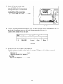
10-4-5
FRAME
50 TERMINAL
(1)
Attach two mount rubbers to the engine base
of the frame. Tighten the nuts from the bottom side of the frame. (See Fig. 10-34.)
8@flange nut . . . . . . . . . . _. . . . . 2 PCS.
Tightening torque : 120 - 140 kg-cm
(2)
Attach the 50 terminal of grounding wires
igreen:yellow) to the unpainted thread hole
of the frame base plate using a 5 mm brass
screw. (See Fig. 10-33.)
60 TERMINAL
(CONTROL
BOX)
80 TERMINAL
{REAR COVER)
Fig. lo-33
- 46 -
(3)
Attach the alternator mount rubber to the frame. (See Fig. 10-34. j
NOTE:
The mount rubbers are selected to reduce vibration most effectively
quency.
Be sure to use the correct mount rubber for your generator.
by model
and its fre-
Fig. 10-34
(4)
Mount the GENERATOR BASE on the mount rubber attached to the frame at step (3).
(See Fig. 10-35.)
84 flange nut . _. . . . . . . . . . . . . . 1 pee.
Tightening torque: 120 - 140 kg-cm
_I
RUBBER
ENGINE
BASE
RUBBER
MOUNT
SIDE
VIEW
MOUNT
Fig. 1035
-47
GENERATOR
-
A
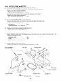
(5)
Attach SHAFT (STOPPER) to the bottom of
engine crankcase.
Tighten nuts tentatively.
NOTE:
(6)
Pay attention
to the position of the
SHAFT (STOPPER).
The flange nuts shall be tightened
a fier fine adjustment.
Cover the both ends of SHAFT (STOPPER)
with RUBBERS. Push RUBBERS until they
touch the crankcase. (See Fig. lo- 36.j
I
SHAFT
&JBBER
(SThPPER)
Fig. 10-36
(7)
Lift engine and alternator assemblv with a
chain block and mount it to the frame.
Down the alternator first then the engine into
the frame.
Lift the engine by approx. 25 mm so as nor to
apply weight to the engine mount rubbers.
(See Fig. 10-37.)
Fig. lo-37
(8;) Fix the legs of rear cover to the generator base.
Attach the 8$ terminal of the grounding wires and the clamp to the right side leg of the rear cover at
the same time.
In the case of electric starting model, attach the 89 terminal of the grounding wires. a clamp and the
BXTTERY CABLE (-j to the right side leg and a clamp to the left side leg of the rear cover at the same
time. (See Fig. 10-38.)
NOTE:
Two nuts are welded to the bottom
side of the GENERATOR
BASE.
80 x 25 mm bolt 8r washer ass>- . . . . 2 PCS.
Tightening torque: 120 - 140 kg-cm
BOLT
CLAMP
iElectrIc
and WASHER
start model)
BATTERY
CABLE I-)
(Electric start model)
fig.
IO-38
- 48 -
ASSY
(9)
Fix the engine mount rubbers to the crankcase
base.
89 flange nut . . . . . . . . . . . . . . . . 2 pcs.
Tightening torque: 120 - 140 kg-cm
CAUTION:
Pay attention to the position of the
mount rubbers.
Lift down the engine and alternator assembly
and remove the chain block belt.
(10)
(11)
Attach two STOPPERS to the frame covering
the both ends of the SHAFT (STOPPER!.
(See Fig. 1O-39. j
6$x 169flangebolt . . . . . . . . . . . 4pcs.
Tightening torque: 50 - 60 kg-cm
fig.
lo-39
Adjust the position of SHAFT (STOPPER) so
as its both ends are placed in the center of the
STOPPERS, then tighten the flange nuts to fix
the SHAFT (STOPPER!. (See Fig. 10-40.)
Tightening torque: 120 - 140 kg-cm
Fig. 1040
(12)
Attach the SIDE PLATE to the frame.
(See Fig. lo-41 .)
Tighten the two black flange bolts tentativel?.
69 x 8 mm flange bolt (black) _ . . . _ 2 PCS.
NOTE:
The flange bolts shall be tightened
after the installation
of the control
box.
Fig. lo-47
- 49 -
10-4-6
CONTROL BOX
Mount the control box assembly to the frame.
Refer to Section 10-S for disassembly-, checking and
reassembly procedures of the control box.
(1)
Attach the 69 terminal of the grounding wires
to the bottom of the control box.
(See Fig. 10-41. j
64 nut (brass) _ . _. . . _ . . . . . . . . . 1 pee.
Tightening torque: 50 - 60 kg-cm
(2)
In the case of generator models equipped Lvith
oil sensor, connect the wires to oil pressure
switch and solenoid.
0 Screw the black/yellow wire to the center of
the oil pressure switch.
l Connect the two blue wires to the solenoid
and clamp the connectors to the side of
speed control unit.
(3)
Connect the wires drawn out from the stator to
the wires from the control box.
Fig. IQ42
NOTE I: Connect the wires of the same color.
NOTE 2: On 220V and 240V models, connect
one blue stator lead with a white
control box lead.
NOTE 3: Engage the connectors securely.
Fig. IO-43
(4)
Push the wires into the control box and attach
the bushing over the wires.
Press the upper end of the bushing into the
control box. (See Fig. 1O-43. j
(5)
Install the control box to the frame.
64x 16mmflangebolt
._......
60x 12mmflangebolt
........
3pcs.
1 pc2.
1
Tighten
the above three bolts tentatively.
2
Tighten the two black bolts which join the side
plate to the frame.
3
Tighten the above three bolts adjusting the
position of the control box. (See Fig. 10-44.)
Tightening torque: 50 - 60 kg-cm
fig. 70-44
< Electric start model >
(6)
Connect the light green and the pink leads of
the control box to the starting motor.
Connect the pink lead to the terminal of the
motor and attach the light green lead together
with the BATTERY CABLE (+) to the 6 mm
bolt of the motor.
(7)
Clamp the wires of starting motor and oil sensor
at the rear panel of control box, main bearing
cover and front cover. (See Fig. 10-45.)
NOTE:
Take a enough margin in the length of
wires between control box and alternator to allow the move of rubber
mounted alternator.
Clamp the BATTERY CABLE (+) to the left
side leg of the rear cover.
-51-
Fig. lo-45
10-4-7
(1)
FUEL TANK
Attach the BRACKET (TANK) to the frame.
(See Fig. 10-46.)
6r$x 16mmflangebolt
. . . . . .._ 3pcs.
Tightening torque: 50 - 60 kg-cm
Fig. 10-46
(2)
Connect fuel pipes to the bottom of the fuel tank. Be careful of the direction of the BANJO.
(See Fig. 10-47.)
‘1
‘,,
-._
/r
-
,BANJO
BOLT
1
PBANJO
IGASKET
;;gg
,
*.-0
63
\
Fig. 70-47
I
Ref.
No.
’
,
I 1
(Aluminlum)
\
FUEL
FILTER
I
Part Name
’ Outer Dia.
FUEL
PIPE
’
12mm
Inner Dia.
i
Length
1
6mm
;
175mm
j
I
4
’
FUEL
PIPE
,
9mm
i
4.5 mm
’
350 mm
1
I
5
i
FUEL
PIPE
;
9mm
,
4.5mm
i
260 mm
1
Table 1 O-2
Use the correct clamps for each fuel pipe.
- 52 -
(3)
Mount the fuel tank on the frame.
-4pply RUBBER (TXNK)s between side plate
and tank. and bracket (tankj and tank.
(See Fig. IO-48.j
Use black flange bolts to join them.
69 x 18 mm flange bolt (black) . . . . 4 PCS.
Tightening torque: 30 - 40 kg-cm
Fig. 70-48
(4)
Connect fuel pipes between fuel tank, fuel cock, fuel filter and fuel injection pump. (See Fig. 10-47.)
Attach the 10 mm flange nut to the fuel cock before connect the fuel pipe to it.
Use the correct clamps for each fuel pipe.
Ref.
No.
I
2
,
FUEL
PIPE
3
-
FUEL
PIPE
Part Name
1 Outer Dia.
I
:
12mm
I
!
12mm
Inner Dia.
6mm
6mm
I
1
I
I
i
Length
70 mm
230mm
‘
Table
(Sj
10-3
Attach fuel cock and fuel filter to the control box.
The fuel cock can be installed on the bracket by turning it 90 depress with fuel pipes connected.
Fuel cock
100 flange nut . . . . . . _ . . _ . . . 1 pee.
Tightenins torque: 50 - 60 kg-cm
Fuel filter
66x 16mmflangenut
. .._...
2pcs.
Tightening torque: 50 - 60 kg-cm
- 53 -
10-4-8
BATTERY
FRAME and BATTERY
(1 j
Attach BATTERY FRAMEs to the frame. (See Fig. 10-49.)
Clamp the upper end of the batter>- frames to the side member of the frame.
Tighten two bolt 8i washers tentatively.
84 x 20 mm bolt & washer ass>- . _ . _ 2 PCS.
Join the lower end of the battery frames to the base plate of the frame.
Tighten two bolt & washers tentatively.
89 x 20 mm bolt 8r washer assy . . . . 2 PCS.
(3)
Mount the BATTERY BASE on the battery frame.
Insert the four bolts from the bottom of the frame and tighten the flange nuts.
6Q x 40 mm bolt & washer assy . _ . . 4 pcs.
69 flange nut . . . . . . . . . . _ . . . . . . .4 PCS.
Tightening torque: 50 - 60 kg-cm
(3)
Tighten the four bolt & washers attached at step (1 j.
Tightening torque: 120 - 140 kg-cm
(4)
Mount the battery on the battery base.
Insert the battery bolts into the hooking holes of the battery base, then apply the battery stay to the
battery and tighten two nuts.
69 spirng washer . . _ . . . . . . . . . . . 2 PCS.
7pcs.
69nut . . . . .._..............
Tightening torque: 50 - 60 kg-cm
(5)
Connect battery cables to the battery.
Connect the positive (+) cable first and then the negative (-1) cable.
BOLT
and WASHER
2 PCS.
BATTERY
BATTERY
CABLE
@--l
BATTERY
BAiTERY
FRAME
BOLT and WASHER
80 x 20 mm: 4 PCS.
- 54 -
BASE
Fig. 70-49
PI-PE FRAME
\
BOLT and WASHER
80
20
2
x mm: PCS.
FLANGE
NUT
60. 4 pcs
lo-5
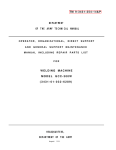
CHECKING, DISASSEMBLY and REASSEMBLY of the CONTROL BOX
10-5-l
CHECKING OF THE CONTROL BOX
Dismount the control box from frame.
Remove the control panel and check each components and Lviring.
Refer to Section 9 for the detail of checking the components in the control box.
10-5-2
DISASSEMBLY
(1)
Remove the control panel irom the control
box.
49 screw. . . . . . . . . . : . . 6 pss.
(2 j
Disconnect the connectors on the wires to detach the control panel and box.
(3)
Remove the regulator. oil sensor unit. condensers and diode rectifier from the control box.
\Vhen removing the regulator. push the hook on
the coupler and pull out to disengage the couplers. (See Fig. 10-50.)
Fig. 70-50
(4)
After disconnecting individual wires. remow the control panel components.
NOTE:
10-5-3
(1 j
DC fuse, full power switch, pilot lamp and warning lamp have their wires soldered.
them to remove those parts if necessary.
Unsolder
REASSEMBLY
Install the receptacles. no-fuse breaksr. fuse. terminals. switches. etc. on the control panel and wire
them.
NOTE:
Circuit diagrams are shown in Section 12. Colored wires are used for easy identification,
and are
of the correct capacity and size. Use heat-resistant type wires (permissible temperature range
75°C or over) in the specified gauge shown in the circuit diagrams.
(2)
Install regulator. oil sensor unit. condensers. and diode rectifier into the control box.
(3)
Connect the ivires of control panel components and control box.
Fasten the earth Lvires to the rear of the control box using a 60 nut to the bolt which fixes the condenser bracket to the inside of the control box. (See Fig. 10-5 1.)
(4)
Attach the control panel to the control box.
40 screiv . . _ . . . . . _ . . . . . . . . . . _ . . . . . 6 pss.
Tightening torque
. . . . . . . . . . . . . . _ . . 13 - 15 kg-cm
CONDENSER
, To EARTH
EARTH
WIRES
BRACKET
TERMINAL
JT
-
Fig. 70-57
- 55 -
11. TROUBLE SHOOTING
11-l
NO AC OUTPUT
11-1-l
CHECKING STATOR
n
Remove control panel and disconnect black. blue.
red, and white wires at the connectors.
n
hleasure the resistance between terminals on stator leads. (.SeeFig. 1 1-l .I
Refer to Table 1 l-l for normal resistance. If stator is fault!-. replace with a ne\v one.
Fig. 77-7
11-l-2
n
CHECKING CONDENSER
If an instrument (QC-meter or C-mew) for meacapad!of condender is availabl?. check
the capacity of condenser. (.SeeFig. 1 l-2. I
CONDENSER
suring
Fig. ? 1-2
m NORW4L CAPACITY OF CONDENSER
NODE L
RGD2500
I
CAPACITY
1s
I ,~,
IL
I
1
RGD3300
I
10,uF
1OpF
1OpF
I
1OpF
Table 7 I- 1
H If such an instrument is unavailable. the condenser can be checked b>-replacing with a new one. If the generator performs good with new condenser. the cause of trouble is defect in original condenser.
- 56 -
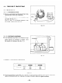
11-1-3
(1)
CHECKING OF ROTOR
CHECKING FIELD COIL
w Measure the resistance of field coil lvith a circuit
tester. (See Fig. 1 I - 3. )
n
NORMAL
RESISTANCE
(R x l.o_~lO%~
Fig. 1 7-3
Table 7 l-2
[Remedy]
If the resistance is not normal. replace rotor Lvith a new one.
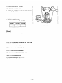
11-2 AC VOLTAGE
11-2-l
IS TOO HIGH OR TOO LOW.
CHECKING STATOR
Check stator referring to Step 1 l- 1- 1.
11-2-2
CHECKING CONDENSER
Check condenser referring to Step 1 1- l-2.
11-2-3
CHECKING ROTOR
Check rotor referring to Step 11-l-3.
- 57 -
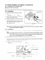
11-3 AC VOLTAGE
11-3-1
IS NORMAL AT NO-LOAD, BUT THE LOAD CANNOT BE APPLIED.
CHECK THE ENGINE SPEED.
If the engine speed is low. adjust it to the rated r.p.m.
11-3-2
CHECK THE TOTAL WATTAGE OF APPLIANCES CONNECTED TO THE GENERATOR.
Refer to Section 7 “RASGE OF APPLICXTIOSS” for the aattage of the appliances.
If the generator is over-loaded. reduce the load to the rated output of ths generator.
11-3-3
CHECK THE APPLIANCE
FOR TROUBLE.
If the appliance is fault>-. repair it.
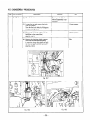
11-3-4
CHECK IF THE ENGINE IS OVERHEATED.
If the cooling air inlet and or cooling air outlet is
clogged with dirt. grass. chaff or other debris. rcmove it.
AIR OL’TLET
Fig. 1 l-4
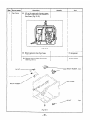
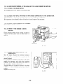
11-3-5
CHECK THE INSULATION
GENERATOR.
OF THE
Stop the engine. Measure the insulation resistance
between the live terminal of th? rezptacle and the
ground terminal.
If the insulation resistance is less than 1 M2. disassemble the generator and check the insulation
resistance of the stator. rotor and the live parts in
the control box. (Refer to Section 8-3.)
Any part lvhere the insulation resistance is l+s than
1 M-151.
the insulation is faulty and may causs clcctric
leakage.
Replace the faulty part.
L
Fig. 7 l-5
- 58 -
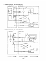
11-4 NO DC OUTPUT
11-4-1
CHECK THE AC OUTPUT.
Check the generator by following Step 1 1- 1- 1 through Step 1 1- l-3.
11-4-2
CHECK THE DC FUSE.
Check the fuse in the fuse holder.
If the fuse is b1oLv-n.check for the cause of fuse
blo\ving. and then replace with a new one.
FUSE : 10-A
NOTE:
If the DC output is used to charge a large
capacity battery or an over-discharged
battery, an excessive current may fro w causing
fuse b/o w.
11-4-3
Fig. 11-6
CHECK THE WIRING.
Check all the wires to be connected correctly.
E RECTIFIER
11-4-4
CHECK THE DIODE RECTIFIER.
Remove
fier with
Refer to
checking
the control panel and check the diode rectia circuit tester.
Section 9-Y “DIODE RECTIFIER” for the
procedure.
Fig. 11-7
11-4-5
CHECK THE DC COIL
Check the resistance bet\veen two bro\vn leads from stator lvith a circuit tester.
r
RESISTANCE
SPECIFICATION
MODEL
50Hz
1 1OV. 22Oi.
11ov 220v
60Hz
120v
I loV~22OV.
50Hz
II OV, 220;.
1 1ov 220v
RG D2500
240V
I
0.16E
0.12,0_
12OV 240V
240V
I
12OV ‘240V
1
0.14Q
RGD3300
‘r-7
‘OH’
1 :::::
220V.
O.llR
Table 1 l-3
If the resistance reading is much larger or smaller than the specifisd value. the DC coil of the stator is faulty.
Replace stator Lvith a new one.
- 59 -
11-5 OIL SENSOR TROUBLE SHOOTING
11-5-l
PRINCIPLE OF OPERATION
The oil sensor for diesel engine consists of a pressure switch as a sensor section and a controller section.
The pressure switch detects the drop of oil pressure in the crankcase. When the oil pressure falls down below
the predetermined value (0.3 kg’cm2 ), turns on the generate a signal to the controller section.
The controller which is powered by the DC coil sets up a delay for a few seconds for detecting signals transmitted during the period.
If more signals than the predetermined number are generated. the controller f2eds power to the solenoid
which actuates the latch on the control bracket to release the control lever to shut the engine down.
11-5-2
TROUBLE SHOOTING
(1 j
Check oil level. Fill it up to maximum level if necessary.
(2)
Check all wires to be connected properly.
If they possibly have breaks in connection, the sensor will also malfunction.
(3 j
Checking the solenoid.
Measure the resistance between two leads from
solenoid. (See Fig. 1 l-8.)
If the resistance is larger or smaller than the
above limits, solenoid is defective.
Replace it Lvith a new one.
Fig. 7 l-8
(4j
Checking the oil sensor unit
(a) Disconnect the connector on the Black:Yellow lead of the oil sensor unit \\-hich is connected to the
pr2ssur2 switch.
(b) Start the engine and ground the Black: Yellow lead of the oil sensor unit to engine body.
(c) If the solenoid actuates to shut the engine down, the oil sensor unit is operating properly-.
(5 j
Checking the pressure switch
(a) Disconnect the Black ‘Yellow lrad of the pressure switch from the control unit.
ib:) Check the resistance betwesn th2 Black Yellow lead and ground.
Resistance should be 00(infinite] when engine is stopp2d.
(c) Start the engine.
The resistance should b2 0 when engine is running.
* The pressure switch actuates at 0.3 kg cm2 oil pressure.
(d) If the pressure switch does not work properly, rsplac2 it with a new one.
- 60 -
12. WIRING DIAGRAM
. RGD2500 : 50Hz-220V, 24OV, 60Hz-220V TYPE
CONTROL
l
RGD2500:
BOX
__
50Hz-1 lOV, 60Hz-1 IOV, 12OV TYPE
4LTERNATOR
-----1
CONTROL
I--
BOX
--
u
CRANGE
--+33--1
-------Oe75mm2
---------1.25mm2
-61-
2.0 mm2
l
RGD2500:
50Hz-1 lOV/22OV, 60Hz-llOV/220V,
CONTROL
LLTERNATOR -m--s
12OV/24OV TYPE
BOX
__
--1
F PSW
NFB
------
l
RGD2500:
U.K., 50Hz-llOV/220V
[BS RECEPTACLE]
CONTROL
.LTERNATOR__-_--
BOX
__
S’”
p
---------
--
______
i
C:?EEN
-_----- “ELLCM
----
1
ORAYGE
f-cc+----
-..--I
0.75 mm2
_-
I-1.25 mm2
__----___
- 62 -
2.0
mm2
. RGD2500:
U.S.A., 60Hz-120V [NEMA RECEPTACLE]
ALTERNATOR
---
CONTROL
---
--1
BOX
--
----
9
hF B
n
0
--SRO’A’N
G R E E ‘4 Y E L L O’<d
i
-E
. RGD2500:
50Hz-220V [FOR EUROPEAN COUNTRIES]
CONTROL
ALTERNATOR
-----
rI rI
BOX
__
REC:
---.-------~
GqEE’d
_____.
E
“E LLCi*i
L
I
/__
-------
--J
i
0.75mm2
b
I
-----_--2V.._L..
--
I----_--__-
- 63 -
~~25~~2
2.0
mm'
.
RGD3300:
50Hz-220V, 24OV, 60Hz-220V TYPE
CONTROL
ALTERNATOR
1
-L-l
I
tlKUWN
J
BOX
I--
1
I
I
I=
--
IZFB\
0 0
1
1
I
~XREEN
YELLOW
J
ORAKGE
r-m----a37
T
3UT
T
--------A
--I
---
.
RGD3300:
50Hz-llOV,
1
4LTERNATOR
-----
--
I
60Hz110V.
GREEN,
--
120V TYPE
:ONTROL
BOX
__
--
1
GREEN;YELLOW
ORANGE
--a-1
r-u3--
-.--
---__-_
-
YELLOVi
I
----__--_
-------
0.75
mm2
___------
1.25mm2
- 64 -
GREEN\
2.0
mm2
.
RGD3300:
50Hz-1 lOV/22OV, 60Hz-1 lOV/22OV. 12OV/24OV TYPE
4LTERNATOR
,
t
;
GREEN
.-
ORANGE
--*-
o-
=-T
?
wcANGE
-__r
l
RGD3300:
U.K., 50Hz-llOV/220V
ALTERNATOR
YELLOW
iiiZi??-A
-
1
-C
--W-1
BLACK
1
-
[BS RECEPTACLE]
CONTROL
BOX
vcs
FC
Jli..--’ ’
KC
I
R
I
:
----la
1;
I
1
!
!
I
I
GREEN
YELLOW
I
ORANGE
I
L
_----
--_
YELLOL’v’
-----__-----
-------_----___-
t------__--
Om75mm2
~~25~~2
- 65 -
2.0
mm2
.
RGD3300:
U.S.A., 60Hz-120V/240V
LTERNATOR
,
[NEMA
CONTROL
RECEPTACLE]
BOX
--
-F F’S’;‘.’
_--31
PEC;
3
,P
il;
12
“’
---------.------_---------- LlGilT
Ph<
-_-___-
0.75 mm2
G9EEN
__________
- _____
- ________
Jli
_
---------1.25mm2
-66-
2.0 mm2
l
RGD3300:
50Hz-220V [FOR EUROPEAN COUNTRIES]
4LTERNATOR
------
CONTROL
DEE?
BOX
__
--
BLUE
‘,SHITE
GREENYELLOW
ORANGE
--J
---
l
RGD2500, RGD3300:
i
--
OIL SENSOR SYSTEM (Optional Equipment)
CONTROLBOX
ALTERNATOR
1
i--J
I----------------,,-,
-----_I 1
YE LLOlzl
:NGINE
-y
SOL
3LUE
--
i
OS
BLUE
--
f=T
0. P. SW
--@
BLACK;Yf
----_-
-------0.75mm2
r
-
GREEN
_---_----_---_----_----
YELLOW
I
-.-i
--
-_
---------1.25mm2
- 67 -
_2.0 mm2
l
RGD2500, RGD3300:
ELECTRIC
JLTERNATOR
SYSTEM (Optional Equipment)
STARTER
:ONTROL
BOX
YELLOW
LIGHT
LIGHT
GREEY
GREEh
l
PIXK
KEY S’.:’
a RGD2500,
RGD3300:
ELECTRIC STARTER AND OIL SENSOR SYSTEM (Optional Equipment)
1ALTERNATOR
CONTROL
BOX
L*-------*‘.
f
1
1;
,
k-n .,E.L*!q
1i
i
c
-r----
-----1
I
1YELLCi,,
L-i--iTe
I------- --------{I,
_----
I__.-__L,re r-e Lx!?-\
-------
)
catz es ...I.-
SACK
--
YE;-LO;:
_-
I
I
--
l
--
I
a c-05s sect or51 are2 a-;er ?a- 2i r-l-l:
0.75mm2
1.25mm2
____--__-
- 68 -
2.0 mm2
Symbols
Parts Name
MC
SC
AC Winding
DC
i Auxiliary Winding
I
( DC Winding
FC
! Field Winding
C
1 Condenser
R
i
D
; Diode Stack Assy
v
; Voltmeter
PL
i Pilot Lamp
T
1 DC Output
Resistor
Terminal
i Fuse
-+---FPSW
REG
OS
i No-Fuse Breaker
I
: Full Power Switch
I
: Regulator
I Oil Sensor
ST.M
I Starting
SOL
I Solenoid
Motor
KEY.SW
1 KEY. Switch
O.P.SW
I Oil Pressure Switch
BAT
E
vcs
i Battery
i Earth Terminal
(Ground
Terminal)
; Voltage Changeover Switch
RECl
; AC Output
Receptacle
(Total
REC2
, AC Output
Receptacle
(22OV/24OV)
REC3
, AC Output
Receptacle
(11 OV/ 12OV)
REC,
, AC Output
Receptacle
(12OV/24OV)
RECj
/ AC Output
Receptacle
(Total 20A MAX.)
- 69 -
15A MAX.)
FUJI
HEAVY
1 USTWIES
LTD.