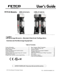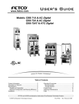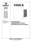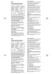
1
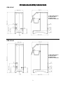
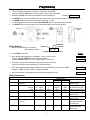
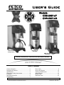
User’s Guide
www.fetco.com
Models:
CBS-2021eP
CBS-2021eG
CBS-2021eP
CBS-2021eP
and L3S-05
and Bowl Server
CBS-2021eG
and L3D-05
NOTICE TO INSTALLER: Please leave this book with the machine.
Table of Contents
Contact Information .............................................. 2
Description & Features ......................................... 2
Specifications........................................................ 2
Dimensions & Utility Connections......................... 3
Installation............................................................. 4
Operating Instructions .......................................... 6
Programming ........................................................ 7
Error Codes ...........................................................9
Service and Support ............................................10
Cleaning & Maintenance .....................................10
Wiring Diagram....................................................11
Brewer Parts ........................................................12
Dispenser Parts ...................................................22
FETCO®, LUXUS®, EXTRACTOR®, CASCADING SPRAY DOME™, and Driven To Pioneer Innovation™ are trademarks or trade names of Food Equipment Technologies Company.
© 2009 Food Equipment Technologies Company
Part # P101 REV. 002
Contact Information
FETCO®
Food Equipment Technologies Company
600 Rose Road
Lake Zurich • IL • 60047-0429 • USA
Phone: (800) 338-2699 (US & Canada)
(847) 719-3000
Fax: (847) 719-3001
Email: [email protected]
[email protected]
Internet: www.fetco.com
Description & Features
The CBS-2021eP brews directly into a 1.9L bowl server or our LUXUS® L3S-05 half-gallon thermal dispenser.
The CBS-2021eG brews directly into our LUXUS® L3D-05 half-gallon thermal dispenser.
The CBS-2021 series features our patented intermittent spray over technology, which works as follows.
The following variables are programmed for each batch size:
Brew volume
Prewet percent
Brew time
Prewet delay
Bypass percent
Drip delay
Using these variables, the software calculates how much water to use for prewetting, bypass and brewing. The
total brew time is divided into several 30-second cycles. Within these cycles, the software calculates how long to
spray water over the coffee grounds, and how long to pause before the next cycle begins.
Features
Two fully programmable batch sizes
Adjustable prewetting cycle
Adjustable bypass
Brew temperature protection
Cascading Spray Dome
Electronically controlled hot water service
Dual coffee filter sizes
Specifications
Requirements
Water Requirements:
Pressure: 20-75 psig
Minimum Flow Rate: ½ gpm
Electrical: See electrical configuration chart.
Coffee Filters: 11¼" X 3 ¾” Product # F007
or 9¾” X 4½” Product # F003
Weights and Capacities
Brewer / Dispenser Model
CBS-2021eP / 1.9L Bowl
CBS-2021eP / L3S-05
CBS-2021eG / L3D-05
Brewer Weight
(empty)
Water tank
Capacity
Brewer Weight
(filled)
Dispenser
Weight (filled)
Total Weight
Brewer & Dispenser(filled)
17.2 lbs.
16.5 lbs.
19.6 lbs.
1.6 gal.
1.6 gal.
2.5 gal.
30.0 lbs.
29.3 lbs.
39.9 lbs.
6.2 lbs.
7.4 lbs.
8.4 lbs.
36.2 lbs.
36.7 lbs.
48.3 lbs.
Electrical Configuration
Electrical
Config. Code
Heater
Configuration
Voltage
(AC)
Phase
Wires
KW
Maximum
Amp draw
Batches
per Hour *
E20046
E20036
E20016
1 X 1.5 KW
1 X 1.7 KW
1 X 2.1 KW
120
120
120
single
single
single
2 + ground
2 + ground
2 + ground
1.5
1.7
2.1
12.9
14.6
17.9
5.7
6.5
8.0
* Based on standard factory settings: 4.0 minute brew time; 0% prewet, 0% bypass; 201 F water.
2
Dimensions & Utility Connections
CBS-2021eP
P- MAIN POWER SWITCH
E- ELECTRIC INPUT
D- DRAIN FITTING
W- WATER CONNECTION
CBS-2021eG
P- MAIN POWER SWITCH
E- ELECTRIC INPUT
D- DRAIN FITTING
W- WATER CONNECTION
3
Installation
(For Qualified Service Technicians Only)
Keys To A Successful Installation
If not installed correctly by qualified personnel, the brewer will not operate properly and damage or injury may
result. Damages resulting from improper installation are not covered by the warranty.
Here are the key points to consider before installation:
Electrical:
All FETCO brewers require NEUTRAL. Ground is not an acceptable substitute. Installation without neutral
may cause damage to the electronic components.
The installation must comply with applicable federal, state, and local codes having jurisdiction at your
location. Check with your local inspectors to determine what codes will apply.
Plumbing:
This equipment is to be installed to comply with the applicable federal, state, or local plumbing codes.
The water line must be flushed thoroughly prior to connecting it to the brewer to prevent debris from
contaminating the machine.
Verify that the water line will provide at least ½ gallon per minute before connecting it to the brewer.
General:
Utilize only qualified beverage equipment service technicians for installation. A Service Company Directory
may be found on our web site, http://www.fetco.com.
Installation Instructions
Brewer Setup
1. Review the Dimensions for the unit you are installing. Verify that the brewer will fit in the space intended for it,
and that the counter or table will support the total weight of the brewer and dispensers when filled.
2. Place the brewer on the counter or stand.
3. When the brewer is in position, use a bubble level to level
the brewer front to back as well as side to side by
adjusting the legs.
Warning: Legs are to be adjusted for
leveling the brewer only. Do not use
for height adjustment or extend them
higher than necessary.
Water Connection
1. Water inlet is a ¼ inch female pipe fitting.
2. Install a water shut off valve near the brewer to facilitate service. If an in-line water filter is used, it should be
installed after the water shut off valve and in a position to facilitate filter replacement.
3. Flush the water supply line and filter before connecting it to the brewer.
4. Verify that the water line will provide at least ½ gallon per minute, and that the water pressure is between 20
and 75 psig.
Electrical Connection
1. Verify that the actual voltage at the electrical outlet is compatible with the
specifications on the brewer’s serial number label.
2. The temperature and water tank fill level are pre-set at the factory.
There is no need to turn off the heaters during the installation process.
The control board disables the heaters until the tank is full of water. The
heating process will start automatically when the tank has filled.
4
Warning: To prevent
electrical shock, this
unit must be properly
grounded.
Final Setup
1. Turn on the incoming water supply line and inspect both inside and outside
of the brewer for leaks in all fittings and tubes
2. Plug the brewer into the appropriate electrical outlet.
3. Turn on the brewer’s main power switch (located on the back of the brewer).
The ON/OFF switch will begin flashing, indicating it is in the OFF position.
The display will read “PRESS KEY”.
4. Press the ON/OFF switch so it is in the ON position (lit, not flashing).
(Note: The switch must be pressed and held momentarily.)
5. Within 6 seconds, the hot water tank will begin filling until the probe at the top
of the tank senses the water. The display will read “FILL”. The control board
will disable the heaters until the tank is full.
6. While the water is heating, the display will read “HEAT” and the actual water
temperature will be displayed. After the water has reached the set
temperature, the display will read “READY”.
7. Review the Operating Instructions. Brew one full batch (water only) to
confirm proper fill levels. The brewer is factory set with water only (no coffee)
to dispense the correct amount of water. If the actual volume is slightly
different from the programmed volume, fine-tuning the brewer may be
necessary. See the Advanced Settings & Diagnostics section.
8. Re- inspect for leaks.
MAIN
POWER
SWITCH
TANK
DRAIN
Operator Training
Review the operating procedures on the next page with whoever will be
using the brewer. Pay particular attention to the following areas:
1. Demonstrate the hot water faucet, paying particular attention to the
safety warning and the correct cup position.
2. Always pre-heat the dispensers before the first use of each day by
filling them half way with hot water, and letting them stand for at least
ON/OFF
15 minutes.
Flashing = OFF
3. Do not remove the brew basket until it has stopped dripping.
Lit = ON
4. Make sure the dispenser is empty before brewing into it.
Dark = Main Power Off
5. Show how to attach covers, close, and or secure the thermal
dispensers for transporting.
6. Demonstrate the daily and weekly cleaning procedures on page 10.
7. Show the location and operation of the water shut off valve as well
as the circuit breaker for the brewer.
8. Steam from the tank will form condensation in the vent tube. This condensation will drip into and then out of the
brew basket. 1/4 cup discharging overnight is possible. Place an appropriate container under the brew basket
when not in use.
9. We recommend leaving the power to the brewer on overnight. The water tank is well insulated and will use very
little electricity to keep the tank hot. Leaving the brewer in the on position will also avoid delays at the
beginning of shifts for the brewer to reach operating temperature.
Tank Drain
The water tank must be drained before certain maintenance procedures, and whenever the unit is to be relocated
or shipped.
1. Disconnect power to the brewer.
2. Move the brewer near a sink or obtain an appropriate container to hold the water from the tank.
(CBS-2021eP: 1.6 gal. / CBS-2021eG: 2.5 gal.)
3. Remove the tank cover and allow the tank to cool to a safe temperature.
4. The tank drain is located on the back of the brewer. Turn the drain plug one-quarter turn in either direction.
5. Pull the plug out far enough to expose the silicone tube.
6. Using pliers, loosen the hose clamp and move it back over the tube.
7. Crimp the tube an inch or two away from the drain plug to prevent water from flowing.
8. Use the other hand to pull the drain plug out of the tube.
9. Release the crimped tube and allow the water to flow into the sink or container.
5
Operating Instructions
Control Panel Functions
Only switches that are active are illuminated.
Switches that are inactive or disabled are invisible.
X Main Power Switch
Controls all power to brewer.
Y Control Panel On/Off Switch
Affects only control panel. Does not
disconnect main power.
Flashing = OFF
Lit = On
Z Brew Switches
Starts brew cycle
Must be held in for 1 second
Flashing = Brew cycle in progress
Lit = Ready to brew
Invisible – Not ready to brew, or batch
disabled
(See Programming Section)
[ Stop Switch
Stops brew cycle
Lit = Brew cycle in progress
Invisible = Not brewing, or dripping in
progress
\ Brew Status
Shows progress of brew cycle.
] Display
Displays the following messages:
PRESS KEY – Control panel is off.
FILL – Water tank is filling.
HEAT –Water is heating.
READY – Machine is ready to brew.
ERROR – Incorrect setup or settingsmachine will not function.
PREWET – Prewet or prewet delay cycle
in progress.
BREW X:XX – Brewing in progress.
Countdown timer shows
brew time remaining.
DRIP X:XX – Drip delay cycle in
progress. Countdown timer
shows drip time remaining.
^
WARNING! Hot water
is dispensed at a
forward angle. Hold
cup slightly forward as
shown.
^ Hot Water Switch
Dispenses hot water from faucet.
Press and hold in to dispense.
See faucet WARNING at right.
Brewing
1. Turn the main power switch and control
panel switch on.
2. Prepare a brew basket with the correct size
filter and appropriate amount of coffee.
3. Slide the brew basket completely into the
rails. A magnet will hold the brew basket in
place.
4. Place a clean, empty, preheated dispenser
under the brew basket.
5. Select a batch from the two choices, and
hold the corresponding BREW button in for
1 second to start the brew cycle.
6. The STOP button will illuminate, and the selected
BREW button will flash, indicating that brewing is
in progress. The other BREW button will
extinguish.
7. When the brew cycle is finished, the BREW
button will continue flashing and the display will
read “DRIP”, indicating that coffee may still be
dripping from the bottom of the brew basket.
8. CAUTION! Before removing the brew basket or
dispenser, visually verify that dripping has
stopped.
6
Programming
Programming Mode
To enter Programming mode, first turn the main power switch OFF.
Press and hold the STOP button while turning the main power switch ON.
Release the STOP button when the software version is displayed.
Example:
VER 32.A
The STOP button is used to advance from one setting to the next. It is green when in Programming mode.
The BREW buttons are used to change each setting up or down.
To exit Programming, press and hold the HOT WATER button for approximately 2 seconds.
The ON/OFF switch may be used to exit programming without saving new settings.
Batch Settings
Batches are numbered 1 (top switch)
and 2 (bottom switch)
PARAMETER
SETTING
BATCH #
1.1
64
Example: Batch 1 – Volume 64 oz.
Press STOP to continue
Display
Next, the first batch parameter is displayed – batch 1, brew volume
Use the UP and DOWN buttons to adjust the setting.
Press the STOP button to go to the next parameter – brew time.
1.1
64
1.2 04:00
Continue this way until all parameters are programmed for batch #1.
(See the chart below for an explanation of each parameter.)
Next, batch #2 programming begins. Batch 2 may be disabled by leaving it set to “OFF”.
Change to “ON” to enable. Batch 1 cannot be disabled.
2.0 OFF
After both batches are programmed, the temperature settings are next.
7
200
Batch Parameters
X=Batch Number (1 - 2)
Parameter
Name
Range
On/Off
X.2
X.3
Batch Enabled or
Disabled
Brew Volume:
ounces
liters
Brew Time (Min:Sec)
Bypass Percent
32 – 80 oz.
0.92 – 2.32 L
01:30-09:30
Off – 30%
X.4
Prewet Percent
Off – 25%
Prewet Delay
X.0
X.1
X.5
Increment
Default Settings
Batch 1
Batch 2
--------
ON
1
0.01
0:15
1%
64 oz
1.85 L
04:00
Off
32oz
0.92 L
03:00
Off
1%
Off
Off
00:00 – 03:00
00:05
00:00
00:00
01:00 – 03:00
00:15
01:30
01:30
(Min:Sec)
X.6
Drip Delay (Min:Sec)
7
Comment
This option is for
batch 2 only.
To change from
ounces to liters, see
Advanced Setting 59.
Percentage of total
brew volume.
Percentage of total
brew volume.
The time between
prewetting and start
of brew cycle.
The time to allow for
dripping after the
brew cycle.
Temperature Settings
Parameter
Name
Range
7
Water Temp. (°F)
176°F - 204°F
201°F
8
Hot Water Service
Auto / On / Off
On
9
Brew Temperature
Protection.
On / Off
On
Name
Range
Enter Advanced
Settings &
Diagnostics
On / Off
Parameter
10
Default Setting
Default Setting
Comment
Inside tank. Will be slightly lower at
spray head. To display in ° Celsius,
see # 58 in Advanced Settings.
Auto= Faucet will dispense only when
not brewing.
On=Faucet always enabled.
Off=Faucet always disabled.
ON=Will brew only at set temperature.
OFF=Will brew at any temperature.
Note: Changes will not take effect until
the next brew cycle is completed.
Comment
Off
OFF = Skip Advanced Settings &
Diagnostics. Loop back to start of
batch programming cycle.
ON = Enter Advanced Settings &
Diagnostics.
Press STOP to continue
Important! After programming, you must press and hold the HOT WATER button to save the settings and exit
programming mode, or changes will be lost.
Advanced Settings and Diagnostics
Address
Description
Range
50
Water Resistance
(KΩ)
0 - 200
51
Water Level
Sensitivity
LO - HI
LO
55
57
Tank Temperature
Reload Defaults
XXX°X
0-1
0
58
59
Temperature Scale
Water Volume
Scale
Brew Valve
Flow Rate
(oz or liters per
minute)
F or C
oz - LTR
F
oz
17 – 51
36
0.50 – 1.50
If #59 is LTR.
1.05
Bypass Valve
Flow Rate
(oz or liters per
minute)
17 – 51
44
60
62
Default
Comment
Displays the electrical resistance of the water in
kilohms as measured between the water level
probe and the tank. If greater than 200, or if the
tank is not full, the display will read – – – .
LO – 50 KΩ +/- 5KΩ
HI – 130 KΩ +/- 5KΩ
If water resistance (address 50) is greater than 25
KΩ, set on HI to prevent unwanted filling of tank.
Displays current tank temperature in °F or °C.
Changes all settings to default factory settings.
0 = Do not reload defaults
1 = Reload all default settings
If 1 is selected, you must advance to the next
address for this change to take effect.
F = Fahrenheit
C = Celsius
oz = Displays volume in ounces.
LTR = Displays volume in liters.
If #59 is oz.
If #59 is oz.
0.50 – 1.50
If #59 is LTR.
1.30
8
Use this to compensate for minor discrepancies in
actual volume versus programmed volume. Set
lower to increase volume, higher to decrease
volume.
Error Codes
Code
Description
Possible Cause
Corrective Action
How to Clear Error
Codes
050
Shorted temperature
probe.
Probe failure.
Replace probe.
Turn main power
switch off and on.
Bad probe connection,
or probe failure, faulty
wire, connectors,
contacts, etc.
Check all connections and
possible failing parts
Replace probe if
necessary.
Watch for short potting
during the brew cycle.
Investigate cause of low
flow rate. (Clogged water
filter, etc.)
Watch for short potting
during the brew cycle.
Investigate cause of low
flow rate. (Clogged water
filter, etc.)
051 or Open temperature probe.
052
Turn main power
switch off and on.
100
Initial Fill Error. Initial fill
time was more than 6
minutes.
Water supply flow rate is
too low.
101
Error on refill. Tank did
not refill within 1 minute.
Water supply flow rate is
too low.
102
Unwanted Fill
When brewer is idle, the
fill valve was activated
for more than 30
seconds during a 1 hour
period.
Possible leak in tank,
fitting, or valve.
Check inside of machine
for leaks.
Turn main power
switch off and on.
200
Flat Line Temperature
(Water is boiling).
Triac failure, bad output
on control board, or
temperature is set too
high for altitude.
Check triac, check control
board output, or adjust
temperature for altitude.
Turn main power
switch off and on.
201
Not heating
Failure of heating
element, triac, triac
control board*, or main
control board.
Check and replace heating
element if necessary.
Check triac, triac control
board*, and main control
board.
Turn main power
switch off and on.
202*
Heater Short
System is not calling for
heat, but temperature
rises more than 5°F.
Possible triac failure, or
bad output on triac
control board* or main
control board.
Check triac, triac control
board*, and main control
board.
Enter programming
mode, then exit
programming mode.
255**
Keyboard error
Stuck button
Replace control board
Turn main power
switch off and on.
Press the control
panel power switch.
Error message is
cleared automatically
at end of brew cycle.
*202 - The triac control board is attached directly to the triac.
TRIAC
TRIAC
CONTROL
BOARD
**255 - The control will only allow hot water to be dispensed for 30-seconds at a time. At 30-seconds, the hot
water output will automatically turn off. If the button is held for more than 34-seconds, error 255 will be
declared.
9
Service and Support
For service and support information, contact the Technical Support department. Our hours are 7:00 AM to 6:00 PM
Central Time, Monday through Friday.
Phone: (800) 338-2699 or (847) 719-3000
Email: [email protected]
Utilize only qualified beverage equipment service technicians for service. A Service Company Directory may be
found on our web site, http://www.fetco.com.
Cleaning & Maintenance
Daily: Wipe the area above the brew basket to remove coffee residue.
Daily or Weekly: Clean the Cascading Spray Dome with a soft brush and
detergent. It may also be cleaned in a dishwasher – top rack only.
The CSD is held in place by four magnets. To remove it, grasp
the bottom and pull down.
Quarterly:
•
Check water temperature and adjust if necessary.
•
Check brew levels and adjust if necessary.
•
Inspect all fittings and hoses for leaks.
•
Inspect inside of tank for lime deposits. De-lime tank and probes if necessary. A qualified service
technician should perform this procedure.
10
Wiring Diagram
11
Brewer Parts
Figure 1 – CBS-2021eP – Main Assembly
12
ITEM #
QTY
PART #
1
2
3
4
5
6
1
1
2
1
1
1
7
1
8
9
10
11
12
13
14
15
16
17
18
19
20
21
22
23
24
25
26
27
1
1
1
1
1
1
1
1
1
1
1
1
1
1
5
1
1
1
1
1
1057.00003.00
1102.00013.00
1082.00010.00
1023.00007.00
1102.00001.00
1024.00005.00
1104.00008.00
1104.00003.00
1104.00001.00
1086.00002.00
1102.00005.00
1051.00003.00
1102.00003.00
1023.00010.00
1086.00003.00
1102.00006.00
1063.00001.00
1029.00002.00
1025.00002.00
1025.00003.00
1025.00004.00
1025.00005.00
1046.00003.00
1086.00001.00
1102.00014.00
1046.00002.00
1044.00001.00
1402.00002.00
1102.00009.00
DESCRIPTION
VALVE, COLD WATER INLET, 24VDC
ADAPTER ASSEMBLY, 3/4" BSP x 1/4" NPT
SCREW, M4x10 ZINC PLATED PAN PHILLIPS MACHINE
TOP, UNIVERSAL
SHELF ASSEMBLY, CBS-2021 COMPLETE (SEE FIG. 5)
GASKET, "U" CHANNEL, 17.0" LONG
TANK ASSEMBLY, CBS-2021P 1500W/120VAC (SEE FIG. 2)
TANK ASSEMBLY, CBS-2021P 1700W/120VAC (SEE FIG. 2)
TANK ASSEMBLY, CBS-2021P 2100W/120VAC (SEE FIG. 2)
CLAMP, HOSE, 0.665-0.783" DIA RANGE
COVER ASSEMBLY, POWER INLET
BOARD, PCB TRIAC DRIVER
HOUSING ASSEMBLY, BREWER FRONT (SEE FIG. 6)
PLUG, TANK SERVICE DRAIN
CLAMP, DRAIN PLUG
CASCADE SPRAY DOME ASSEMBLY, CBS-2021
CORD, POWER, IEC-320-19, 20 AMP
FITTING, HOSE BARB TEE, SIZE 3/8" , NYLON
TUBE, 5/8"OD X 3/8"ID X 11.5"LG, COLD WATER INLET
TUBE, 5/8"OD X 3/8"ID X 10"LG, TANK DRAIN
TUBE, 5/8"OD X 3/8"ID X 8"LG, TANK WATER INLET
TUBE, 1/2"OD X 1/4"ID X 7"LG, VENT
LABEL, CSD WARNING, 1.5" X 5.0"
CLAMP, HOSE, .590"-.673" DIA RANGE
COVER ASSEMBLY, POWER SUPPLY
LABEL, CAUTION, "RISK OF FIRE AND ELECTRIC SHOCK"
LABEL, "FOR USE ON INDIVIDUAL BRANCH CIRCUIT ONLY"
HARNESS, CBS-2021, UNIVERSAL
TRAY, ASSEMBLY,2021P
13
Figure 2 – CBS-2021eP – Tank Assembly, Part # 1104.00008.00 (1500 W heater)
Part # 1104.00003.00 (1700 W heater)
Part # 1104.00001.00 (2100 W heater)
14
ITEM #
QTY
1
2
3
4
5
6
7
8
9
10
11
12
1
1
1
2
2
2
1
1
1
1
1
1
13
1
14
1
PART #
1114.00003.00
1024.00007.00
1102.00007.00
1023.00003.00
1083.00006.00
1025.00001.00
1112.00008.00
1102.00011.00
1059.00001.00
1003.00006.00
1003.00005.00
1053.00004.00
1107.00004.00
1107.00003.00
1107.00001.00
1022.00004.00
DESCRIPTION
TANK WELDMENT, STUDS, CBS-2021P
O-RING, DASH #344, TANK COVER
TANK COVER ASSEMBLY
LOCKNUT, 1/4"-18 NPT MODIFIED THREAD
WASHER, .875"OD X .562"ID, FLAT
FITTING, COMPRESSION MALE CONNECTOR
PROBE WELDMENT, WATER LEVEL 1.875" LONG
PROBE ASSEMBLY, DIGITAL TEMP. 5.0" LG.
TRIAC 40A, 600V
BRACKET, HEAT SINK
BRACKET, ONE SHOT THERMOSTAT
THERMOSTAT, SINGLE SHOT, 25 AMP
HEATER ASSEMBLY, IMMERSION 1500W/120VAC
HEATER ASSEMBLY, IMMERSION 1700W/120VAC
HEATER ASSEMBLY, IMMERSION 2100W/120VAC
INSULATION, TANK, CBS-2021P
15
Figure 3 – CBS-2021eG – Main Assembly
16
ITEM #
QTY
PART #
1
2
3
4
5
6
1
1
2
1
1
1
7
1
8
9
10
11
12
13
14
15
16
17
18
19
20
21
22
23
24
25
26
1
1
1
1
1
1
1
1
1
1
1
1
1
1
5
1
1
1
1
1057.00003.00
1102.00013.00
1082.00010.00
1023.00007.00
1102.00001.00
1024.00005.00
1104.00009.00
1104.00004.00
1104.00002.00
1086.00002.00
1102.00005.00
1051.00003.00
1102.00003.00
1023.00010.00
1086.00003.00
1102.00006.00
1063.00001.00
1029.00002.00
1025.00002.00
1025.00003.00
1025.00004.00
1025.00005.00
1046.00003.00
1086.00001.00
1102.00014.00
1046.00002.00
1044.00001.00
1402.00002.00
DESCRIPTION
VALVE, COLD WATER INLET, 24VDC
ADAPTER ASSEMBLY, 3/4" BSP x 1/4" NPT
SCREW, M4x10 ZINC PLATED PAN PHILLIPS MACHINE
TOP, UNIVERSAL
SHELF ASSEMBLY, CBS-2021 COMPLETE (SEE FIG. 5)
GASKET, "U" CHANNEL, 17.0" LONG
TANK ASSEMBLY, CBS-2021G 1500W/120VAC (SEE FIG. 4)
TANK ASSEMBLY, CBS-2021G 1700W/120VAC (SEE FIG. 4)
TANK ASSEMBLY, CBS-2021G 2100W/120VAC (SEE FIG. 4)
CLAMP, HOSE, 0.665-0.783" DIA RANGE
COVER ASSEMBLY, POWER INLET
BOARD, PCB TRIAC DRIVER
HOUSING ASSEMBLY, BREWER FRONT (SEE FIG. 6)
PLUG, TANK SERVICE DRAIN
CLAMP, DRAIN PLUG
CASCADE SPRAY DOME ASSEMBLY, CBS-2021
CORD, POWER, IEC-320-19, 20 AMP
FITTING, HOSE BARB TEE, SIZE 3/8" , NYLON
TUBE, 5/8"OD X 3/8"ID X 11.5"LG, COLD WATER INLET
TUBE, 5/8"OD X 3/8"ID X 10"LG, TANK DRAIN
TUBE, 5/8"OD X 3/8"ID X 8"LG, TANK WATER INLET
TUBE, 1/2"OD X 1/4"ID X 7"LG, VENT
LABEL, CSD WARNING, 1.5" X 5.0"
CLAMP, HOSE, .590"-.673" DIA RANGE
COVER ASSEMBLY, POWER SUPPLY
LABEL, CAUTION, "RISK OF FIRE AND ELECTRIC SHOCK"
LABEL, "FOR USE ON INDIVIDUAL BRANCH CIRCUIT ONLY"
HARNESS, CBS-2021, UNIVERSAL
17
Figure 4 – CBS-2021eG – Tank Assembly, Part # 1104.00009.00 (1500 W heater)
Part # 1104.00004.00 (1700 W heater)
Part # 1104.00002.00 (2100 W heater)
18
ITEM #
QTY
PART #
1
2
3
4
5
6
7
8
9
10
11
12
1
1
1
2
2
2
1
1
1
1
1
1
13
1
14
1
1114.00004.00
1024.00007.00
1102.00007.00
1023.00003.00
1083.00006.00
1025.00001.00
1112.00008.00
1102.00010.00
1059.00001.00
1003.00006.00
1003.00005.00
1053.00004.00
1107.00004.00
1107.00003.00
1107.00001.00
1022.00005.00
DESCRIPTION
TANK WELDMENT, STUDS, CBS-2021G
O-RING, DASH #344, TANK COVER
TANK COVER ASSEMBLY
LOCKNUT, 1/4"-18 NPT MODIFIED THREAD
WASHER, .875"OD X .562"ID, FLAT
FITTING, COMPRESSION MALE CONNECTOR
PROBE WELDMENT, WATER LEVEL 1.875" LONG
PROBE ASSEMBLY, DIGITAL TEMPERATURE 8.0" LG
TRIAC 40A, 600V
BRACKET, HEAT SINK
BRACKET, ONE SHOT THERMOSTAT
THERMOSTAT, SINGLE SHOT, 25 AMP
HEATER ASSEMBLY, IMMERSION 1500W/120VAC
HEATER ASSEMBLY, IMMERSION 1700W/120VAC
HEATER ASSEMBLY, IMMERSION 2100W/120VAC
INSULATION, TANK, CBS-2021G
19
Figure 5 – CBS-2021e - Shelf Assembly, Part # 1102.00001.00
ITEM #
QTY
PART #
1
2
3
4
5
6
7
8
3
3
6
1
1
1
3
1
1024.00002.00
1057.00004.00
1082.00005.00
1003.00002.00
1024.00004.00
1024.00003.00
1086.00001.00
1022.00003.00
DESCRIPTION
O-RING, AS568A-019, BUNA-N
VALVE, LOW PRESSURE, 24VDC
SCREW, #7 x 5/8" LG, PHIL PAN HD TYPE AB, SHEET METAL, Z/P
BRACKET, GASKET CBS-2021
GASKET, "U" CHANNEL, 6.75" LONG
TUBE, WATER DISTRIBUTION, CBS-2021
CLAMP, HOSE, .590"-.673" DIA RANGE
INSULATION, BREW TUBE, CBS-2021
Figure 6 – CBS-2021e - Housing Assy., Brewer Front, Part# 1102.00003.00
ITEM #
QTY
PART #
1
2
3
1
4
1
1108.00001.00
1081.00002.00
1041.00003.00
DESCRIPTION
BOARD, ASSEMBLY, PCB CONTROL CBS-2021
STANDOFF, 4.5MM HEX x 20MM x M3 THREAD
LABEL, CAUTION HOT WATER
20
Figure 7 – CBS-2021e - Brew Basket Assembly, Part # 1101.00001.00
ITEM #
QTY
PART #
1
2
3
4
5
6
7
8
9
10
1
1
1
1
1
1
1
1
1
1
1004.00001.00
1046.00001.00
1082.00002.00
1082.00001.00
1023.00001.00
1083.00002.00
1084.00003.00
1009.00001.00
1009.00002.00
1102.00012.00
DESCRIPTION
BREW CONE, 5MM DRAIN HOLE
LABEL, WARNING BREW BASKET
SCREW, 8x1/2" 18-8 FLAT PHILLIPS AB THREAD-FORMING
SCREW, M4x10 18-8 FLAT PHILLIPS MACHINE
HANDLE, BREW BASKET
WASHER, M4 18-8 MACHINE SCREW
NUT, M4 18-8 HEX CAP
WIRE BASKET, LARGE
WIRE BASKET, SMALL
HOUSING, BREW BASKET MAGNET ASSEMBLY
21
Dispenser Parts
Figure 8 – LUXUS® L3D-05 Dispenser, Product # D058
LUXUS® L3S-05 Dispenser, Product # D059
ITEM #
QTY
PART #
1
2
3
4
5
6
7
8
9
10
1
1
1
1
1
1
1
1
1
5
1023.00017.00
1023.00018.00
1102.00017.00
1102.00018.00
1023.00019.00
1024.00011.00
1023.00020.00
1023.00021.00
1023.00022.00
1082.00013.00
11
3
1029.00003.00
12
13
1
1
1024.00012.00
1071.00002.00
13a
1
13b
14
1
1
1071.00009.00
1071.00003.00
1071.00004.00
1071.00005.00
1071.00006.00
1086.00005.00
15
1
1086.00006.00
16
17
1
2
1025.00008.00
1082.00012.00
18
1
1074.00001.00
DESCRIPTION
TOP
BOTTOM
FUNNEL ASSEMBLY
COVER ASSEMBLY
HANDLE
LINER GASKET
FAUCET GUARD
BASE
DRIP PLATE
SCREW, M4x8MM SOCKET
HEAD CAP,
PLUG, UNVENTED, 8MM
OD, L3D-05
ELBOW, SILICONE
UPPER FAUCET
ASSEMBLY, MS, BLACK,
M28 THREAD
FAUCET HANDLE, BLACK
FAUCET HANDLE, GREEN
FAUCET HANDLE, RED
FAUCET HANDLE, ORANGE
FAUCET SEAT CUP
CLAMP, HOSE, ID 13.5MM15.0MM
CLAMP, HOSE, ID 18.1MM20.0MM
FOOT, ANTI SLIP
SCREW, #10 X 3/4”, ZINC
PLATED, HEX WASHER
HEAD
CLEANING BRUSH
ITEMS 8, 9, 16 AND 17 ARE
NOT USED ON L3S-05.
SEE FIGURE 9 FOR
OPTIONAL S3S-05-01 STAND.
22
Figure 9 – S3S-05-01 Stand, Product # A134
(For L3S-05 Dispenser)
ITEM #
QTY
PART #
DESCRIPTION
1
1
1101.00013.00
ASSEMBLY, STAND, S3S-05-01
2
1
1023.00022.00
DRIP PLATE
Figure 10 – 1.9 Liter Bowl Server, # D055
ITEM
1
23
QTY
PART #
DESCRIPTION
1
1099.00002.00
LID, BLACK
1
1099.00003.00
LID, ORANGE