1
Save
ThisReference
Manual
r Future
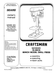
MODEL NO,
!t3.2!3080
DRILL PRESS WITH
MAXIMUM
DEVELOPED
I/3 HP MOTOR
Serial
Number
Model and serial number
may be found at the rear of
the head.
You should record both
model and serial number in
a safe place for future use.
MOTOR|ZED
8-INCH
BENCH MODEL DRILL PRESS
CAUTION'.
• assembly
• operating
• repair parts
READ ALL
INSTRUCTIONS
CAREFULLY
J
Sold by SEARS, ROEBUCK
Part No. SP5184
J
AND
CO., Chicago,
_L60684
U.S.A.
Printed in Taiwan
FULL ONE YEAR WARRANTY
ON CRAFTSMAN
DRILL PRESS
If within one year from the date of purchase, this Craftsman Drill Press fails due to a defect
in material or workmanship, Sears will repair it, free of charge.
WARRANTY SERVICE IS AVAILABLE BY SIMPLY CONTACTING THE NEAREST SEARS SERVICE CENTER/DEPARTMENT THROUGHOUT THE UNITED STATES.
This warranty applies only while this product is used in the United States.
This warranty gives you specific legal rights, and you may also have other rights which
vary from state to state.
SEARS, ROEBUCK AND CO., Dept. 698/731A, Sears Tower, Chicago, IL 60684
GENERAL
SAFETY
iNSTRUCTiONS
1. KNOW YOUR POWER TOOL
Read and understand the owner's manual and
labels affixed to the tool. Learn its application and
limitations as well as the specific potential hazards
peculiar to this tool.
2. GROUND ALL TOOLS
This tool is equipped with an approved 3-conductor
cord and a 3-prong grounding type plug to fit the
proper grounding type receptacle. The green conductor in the cord is the grounding wire. Never
connect the green wire to a live terminal.
3. KEEP GUARDS IN PLACE
In working order, and in proper adjustment and
alignment.
4. REMOVE ADJUSTING KEYS AND WRENCHES
Form a habit of checking to see that keys and
adjusting wrenches are removed from tool before
turning it on.
5. KEEP WORK AREA CLEAN
Cluttered areas and benches invite accidents. Floor
must not be slippery due to wax or sawdust.
6. AVOID DANGEROUS ENVIRONMENT
Don't use power tools in damp or wet locations or
expose them to rain. Keep work area well lighted.
Provide adequate surrounding work space.
7. KEEP CHILDREN AWAY
All visitors should be kept a safe distance from
work area.
8. MAKE WORKSHOP CHILD-PROOF
With padlocks, master switches by removing starter keys, or storing tools where children can't get
them,
9. DON'T FORCE TOOL
It will do the job better and safer at the rate for
which it was designed.
10. USE RIGHTTOOL
Don't force tools or attachment to do a job it was
not designed for.
11. WEAR PROPER APPAREL
Do not wear loose clothing, gloves, neckties, or
jewelry (rings, wrist watches) to get caught in moving parts. NONSLIP footwear is recommended.
Wear protective hair covering to contain long hair.
Roll long sleeves above the elbow.
12. USE SAFETY GOGGLES (HEAD PROTECTION)
Wear safety goggles (must comply with AINSl
13.
14.
15.
16.
17.
18.
19.
20.
21.
22.
FOR POWER TOOLS
Z87.1) at all times. Everyday eyeglasses are not
safety glasses. They only have impact resistant
lenses. Also, use face or dust mask if cutting operation is dusty, and ear protectors (plugs or muffs)
during extended periods of operation.
SECURE WORK
Use clamps or a vise to hold work when practical.
It frees both hands to operate tool.
DON'T OVERREACH
Keep proper footing and balance at all times.
MAINTAIN TOOLS WiTH CARE
Keep tools sharp and clean for best and safest
performance. Follow instructions for lubricating and
changing accessories.
DISCONNECT TOOLS
Before servicing; when changing accessories such
as blades, bits, cutters, etc.
AVOID ACCIDENTAL STARTING
Make sure switch is in "OFF" position before plugging in.
USE RECOMMENDED ACCESSORIES
Consult the owner's manual for recommended accessories. Follow the instructions that accompany
the accessories. The use of improper accessories
may cause hazards.
NEVER STAND ON TOOL OR iTS STAND
Serious injury could occur if the tool is tipped or if
the cutting tool is accidentally contacted. Do not
store materials above or near the tool such that it
is necessary to stand on the tool or its stand to
reach them.
CHECK DAMAGED PARTS
Before further use of the tooJ. a guard or other part
that is damaged should De carefully checked to
ensure that it will operate properly an€ perform its
intended function. Check for alignment of moving
parts, binding or moving parts, breakage of parts,
mounting, and any other conditions that may affect
its operation. A guard or other part that is damaged
should be properly repaired or replaced.
DIRECTION OF FEED
Feed work into a blade or cutter against the direction of rotation of the blade or cutter only.
NEVER LEAVETOOL RUNNING UNATTENDED
Turn power off. Don't leave toot until it comes to a
complete stop.
additional
safety instructions
_VARNING:
FOR YOUR OWN SAFETY,
DO NOT
_,TTEMPT
TO OPERATE
YOUR
DRILL
PRESS
JNT_L RT _S COMPLETELY
ASSEMBLED
AND INSTALLED ACCORDING
TO THE INSTRUCTHONS...
_ND UNTIL YOU HAVE READ AND UNDERSTAND
THE FOLLOWING:
1. General
Safety
2. Getting
to Know
3. Basic
Drill
Instructions
Press
Your
Drill
Operation
for Power
Press
Tools.
........
.............
for driJl presses
--
2
15
--
19
4. Adjustments
..........................
2t
5. Maintenance
..........................
22
6. Stability
of Drill Press
If there is any tendency of the drill press to tilt or
move during any use, bolt it to the floor or a fiat
piece of 1/2" exterior plywood
large enough to
stabilize the drill press. Bolt the plywood to the
underside
of the Base, so it extends at least to
both sides. Make sure the plywood won't trip the
operator. Do not use pressed wood panels-they can break unexpectedly.
---
--
with
--
7. Location
Use the drill press in a well lit area and on a level
surface clean and smooth enough to reduce the
risk of trips, slips, or falls. Use it where neither the
operator nor a casual observer is forced to stand
in line with a potential kickback.
--
If the workpiece is too large to easily support
one hand, provide an auxiliary support.
--
--
8. Kickback
A kickback occurs when the workpiece is suddenly
thrown in the OPPOSITE
direction to the DIRECTION OF FEED; THIS CAN CAUSE SERIOUS INJURY. Kickbacks are most commonly caused by
use of accessories NOT recommended
for this tool.
--
Guard for drilling information;
for accessories, refer to the instructions
provided
with the accessories.
g. Protection: Eyes, Hands, Face, Ears and Body
WARNING: TO AVOID BEING PULLED INTO
THE SPINNING TOOL -1. Do
----2. Do
d. To prevent the workpiece
from being
torn from your hands, spinning of the
toot, shattering the tool or being thrown,
always properly support your work so
it won't shift or bind on the tool:
Always position BACKUP MATERIAL (use
beneath the workpiece)
to contact the left
side of the column.
Whenever
possible,
position the WORKPIECE to contact the left side of the column-if
it is too short or the table is tilted,
clamp solidly to the table. Use table slots
or clamping ledge around the outside edge
of the table.
When using a drill press VICE, always fasten it to a table.
Never do any work "FREEHAND"
(handholding workpiece rather than supporting
it
on the table), except when polishing.
Securely lock Head and Support to Column,
Table Arm to support, and Table to Table
Arm before operating drill press.
Never move the Head or Table while the
tool is running.
Before starting the operation, jog the motor
switch to make sure the drill or other cutting
tool does not wobble or cause vibration.
If a workpiece
overhangs
the table such
that it will fall or tip if not held, clamp it to
the table or provide auxiliary support.
Use fixtures
for unusual
operations
to
adequately
hold, guide and position workpiece.
Use the SPINDLE
SPEED recommended
for the specific operation
and workpiece
material--check
the inside
of the Belt
f. Never climb on the drill press Table, it
could break or pull the entire drill press
down on you.
NOT wear:
gloves
necktie
loose clothing
jewelry
tie back long hair
g. Turn the motor Switch Off and put away
the Switch Key when leaving the drill
press.
h. To avoid injury from thrown work or tool
contact, do NOT perform layout, assembly, or setup work on the table while
the cutting tool is rotating.
a. If any part of your drill press is missing, malfunctioning, has been damaged or broken..,
such
as the motor switch, or other operating control,
a safety device or the power cord . . , cease
operating immediately until the particular part
is properly repaired or replaced.
b. Never place your fingers in a position where
they could contact the drill or other cutting tool
if the workpiece should unexpectedly shift or
your hand should slip.
t0.
Use only accessories
designed for this
drill press to avoid serious injury from
thrown
broken parts or work pieces.
a. Holesaws must NEVER be operated on
this drill press at a speed greater than
4OO RPM.
c. To avoid injury from parts thrown by the spring,
follow instructions exactly as given and shown
in adjusting spring tension of quill.
3
2
b. Drum sanders must NEVER be operated on
this driU press at a speed greater than 1800
RPM
c. Do not install or use any drill that exceeds 7" in
length or extends 6" below the chuck jaws, They
can suddenly bend outward or break.
d. Do not use wire wheels, router bits. shaper cutters, circle (fly) cutters or rotary planers on this
drill press.
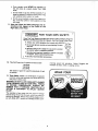
11. Note and Follow the Safety Warnings and Instructions that Appear on the Panel on the
Right Side of the Head:
f
O
o
FOR YOUR OWN SAFETY:
KnowThis Tool! Read and Understand Owner'sManual beforeUsing this
Machine.Use Recommended Drill Speed- SeeChart Inside Pulley Cover.
m Always wear safety goggles that comply with ANSI Z87.1
m Donotwear gloves,necktie or looseclothing.Tie back
_E
long hair.
= Securelyclamp work to table if itis too shorttocontact
the column when in operating position.
!
Securely lock head and support to column, and table
to support, before operating drillpress.
'-_N
O m Use only recommended accessories.
12. This Drill Press has 3 speeds as listed below:
620 RPM
1300 RPM
3100 RPM
See inside of guard for specific placement of belt
on pulleys.
13. Think Safety. Safety is a combination of operator
common sense and alertness at all times when the
drill press is being used,
WARNING: DO NOT ALLOW FAMILIARITY (GAINED
FROM FREQUENT USE OF YOUR DRILL PRESS)
TO BECOME COMMONPLACE.
ALWAYS
REMEMBER THAT A CARELESS FRACTION OF A
SECOND IS SUFFICIENT TO INFLICT SEVERE
INJURY.
The operation of any power tool can resutt in foreign
objects being thrown into the eyes. which can result _n
severe eye damage. Always wear safety goggles comply with ANSI Z87.1 (shown on Package) before corn-
F_82443O
mencing power tool operation. Safety Goggles are
available at Sears retail or catalog stores.
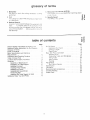
gJossary
!.
Workp_ece
The item on which the cutting
performed.
operations
is bei_g
2. O_igl
The cutting tool used ir_ the dritt press to make hoies
in a workpiece.
3. Backup
of terms
4. Revolution
Per Minute (R.P.M.)
The nur_',,b,erof t_Jrns corr_pteted
by a spinning
object
in one mint_te
5, Spindle
Speed
-t'b,,,,, RPM of the spindie,
_
_
r_
o
o
Material
A piece of wood piaced between the workpiece and
table ....
it prevents wood in the workpiece from
splintering when the drill passes through the back°
side of the workpiece .... also prevents driliing into
the table top.
Q
table of contents
t.D
Page
General Safety Instructions for Power Tools ......
2
Additional Safety Instructions
for Drill Presses
....
3
Glossary of Terms
.......................
5
Table of Contents ...........................
5
Motor Specifications
and Electrical
Requirements
..............................
6
Unpacking and Checking Contents
.............
7
Table of Loose Parts ........................
8
Location and Function of Controls ..............
9
Assembly
................................
!0
Assembly of Base/Column
...............
10
Installation of Table/Support
..............
t0
Installing the Head .....................
1t
Installing Feed Handles
.................
12
Installing the Chuck .....................
12
Installing Belt Guard Knob ...............
!3
Tensioning
Belt .......................
13
Adjusting the Table Square to Head .......
!4
Getting to Know Your Drill Press .............
15
OnoOff Switch ............................
Removing ti_e Chuck ....................
Drilling to Deplh
.......................
Depth ScaIe ............................
Basic Drift Press Operation
..................
installing Dritis .........................
Positioning Table and Workpiece
..........
Tdting Table ..............................
Hole Location
.........................
Feeding ...............................
Adjustments
..............................
Quill Return Spring
.....................
Maintenance
..............................
Lubrication
...............................
Recommended
Accessories
..................
Trouble Shooting
..........................
Repair Parts ..............................
Page
17
18
18
18
19
19
20
20
2t
21
21
21
22
22
22
23
24
meter specifications and e ectricaJ requirements
MOTOR SPECIFmCATmONS
This power tool is equipped with a 3-conductor cord
and grounding type plug, approved by Underwriters'
Laboratories and the Canadian Standards Association.
The ground conductor has a green jacket and is attached to the tool housing at one end and to the ground
prong in the attachment plug at the other end.
This drill press is designed to use a 1725 RPtvl motor
only. Do not use any motor that runs faster than t725
RPM. It is wired for operation on 110-120 volts, 60 Hz.
alternating current.
WARNING:
TO AVOID iNJURY FROM UNEXPECTED STARTUP, DO NOT USE BLOWER OR
WASHING MACHINE MOTORS OR ANY MOTOR
WiTH AN AUTOMATIC RESET OVERLOAD PROTECTOR.
This plug requires a mating 3-conductor grounded type
outlet as shown,
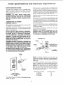
CONNECTING TO POWER
SOURCE OUTLET
If the outlet you are planning to use for this power tool
is of the two prong type, DO NOT REMOVE OR ALTER
THE GROUNDING PRONG IN ANY MANNER. Use
an adapter as shown and always connect the grounding
tug to known ground.
This machine must be grounded while in use to protect
the operator from electric shock.
It is recommended that you have a qualified electrician
replace the TWO prong outlet with a properly grounded
THREE prong outlet.
Plug power cord into a 110-120V properly grounded
type outlet protected by a 15-amp. dual element time
delay or Circuit breaker.
NOT ALL OUTLETS ARE PROPERLY GROUNDED.
IF YOU ARE NOT SURE THAT YOUR OUTLET, AS
PICTURED BELOW, IS PROPERLY GROUNDED,
HAVE IT CHECKED BY A QUALIFIED ELECTRICIAN.
An adapter as shown below is available for connecting
plugs to 2-prong receptacles.
WARNING: THE GREEN GROUNDING LUG EXTENDING FROM THE ADAPTER MUST BE CONNECTED TO A PERMANENT GROUND SUCH AS
TO A PROPERLY GROUNDED OUTLET BOX.
WARNING: TO AVOID ELECTRIC SHOCK, DO NOT
TOUCH THE METAL PRONGS ON THE PLUG,
WHEN INSTALLING OR REMOVING THE PLUG TO
OR FROM THE OUTLET.
GROUNDING
WARNING: FAILURE TO PROPERLY GROUND THIS
POWER TOOL CAN CAUSE ELECTR|CUTION OR
SERIOUS SHOCK, PARTICULARLY WHEN USED IN
DAMP LOCATIONS, OR NEAR METAL PLUMBING.
IF SHOCKED, YOUR REACTION COULD CAUSE
YOUR HANDS TO HIT THE CUTTING TOOL.
SCR_\
3-PRONG
LUG
D_
_
MAKE
SURE
THISIS
IF POWER CORD IS WORN OR CUT, OR DAMAGED
IN ANY WAY, HAVE IT REPLACED IMMEDIATELY
TO AVOID SHOCK OR FIRE HAZARD.
ADAPTER
3-PRONG
PLUG
NOTE: The adapter illustrated is for use only if you
already have a properly grounded 2-prong receptacle.
Adapter is not allowed in Canada by the Canadian Electrical Code.
\
The use of any extension cord will cause some loss of
power, To keep this to a minimum and to prevent overheating and motor burn-out, use the table below to
determine the minimum wire size (A.W.G.) extension
cord. Use only 3 wire extension cords which have 3prong grounding type plugs and 3-pole receptacles
which accept the tools plug.
\
GROUNDING
PRONG
\
Extension Cord Length
0-25 Feet
26-50 Feet
51-100Feet
\
ALWAYS USE A
PROPERLY GROUNDED
OUTLET
Yourunitis _ruse on 120 votts, ithas a plugth_
like Me one above.
looks
6
WireSize A.W.G.
16
14
12
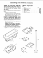
unpacking
and checking
WARNING: TO AVOID INJURY FROM UNEXPECTED STAF_TING OR ELECTRICAL SHOCK, DO
NOT PLUG THE POWER CORD iNTO A SOURCE
OF POWER. THiS CORD MUST REMAIN UNPLUGGED WHENEVER YOU ARE WORKING ON THE
DRILL PRESS.
Model 113.213080 Drill Press is shipped complete in
one box.
1. Unpacking and Checking Contents
contents
TABLE OF LOOSE PARTS
item
A
B
C
D
E
F
G
Description
Table/Support Asm ....................
Column Support Asm ..................
Owner's Manual ......................
Box of Loose Parts ...................
Base ...............................
Head Asm
.......................
Bag of Loose Parts
Qty.
1
1
1
1
1
1
t
a. Separate all "loose parts" from packaging materials and check each item with "Table of Loose
Parts" to make sure all items are accounted for,
before discarding any packing material.
WARNING: iF ANY PARTS ARE MISSING, DO NOT
ATTEMPT TO ASSEMBLE DRILL PRESS, PLUG IN
THE POWER CORD, OR TURN THE SWITCH ON
UNTIL THE MISSING PARTS ARE OBTAINED AND
ARE iNSTALLED CORRECTLY.
2. Remove the protective oil that is applied to the
table and column. Use any ordinary household type
grease and spot remover.
WARNING: TO AVOID FIRE OR TOXIC REACTION, NEVER USE GASOLINE, NAPTHA OR
SiMiLAR HIGHLY VOLATILE SOLVENTS.
3. Apply a coat of paste wax to the table and column
to prevent rust. Wipe all parts thoroughly with a clean
dry cloth.
C)
\
.....--B
F
C
,,_
=
_ "_
o
.=_
"_
__ L,_
:_ _'
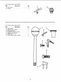
List of Loose Parts in Box 507870
Item
A
B
Description
Chuck Key ..........................
Chuck. .............................
Qty.
1
1
List of Loose Parts in Bag 507871
Item
A
B
C
D
E
F
G
Description
Feed Handle ........................
Wrench Hex "L" 4rnm .................
Belt Guard Knob .....................
Screw Pan Hd. M5 x 0.8-12 ............
Support Lock Handle ..................
Switch Key ..........................
Screw Hex Hd. M8 x 1,25-20 ...........
Qty.
3
1
1
1
1
1
3
D
!
G
....=.==.
8
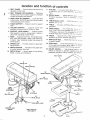
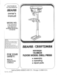
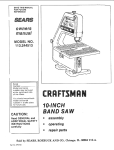
location and function
of controls
1. BELT GUARD...
Covers pulleys and belt during
operation of drill press,
2. BELT TENSION LOCK HANDLES...
Tightening
handles locks motor bracket support to maintain
correct belt distance and tension.
3. HEAD LOCK SET SCREWS...
Locks the head
to the column. ALWAYS have them locked in place
while operating the drill press,
4. TABLE SUPPORT,..
Rides on column to support
table.
11. COLUMN...
5. COLUMN SUPPORT . . . Supports column and
provides mounting holes for column to base.
15.
Connects
a one-piece
ment.
12,
13.
14.
6. SUPPORT LOCK HANDLE...
Tightening locks
table support to column, Always have it locked in
place while operating the Drill Press.
BEVEL SCALE...
for bevel operations.
support.
TABLE
position
TABLE
...
workpiece.
Provides
alignmer_t
Shows
Scale
BEVEL LOCK...
from 0-45
_............
ar_:_, mo,-_
'-'
degree
table _s tied
is mounted
on ta_:>e
Locks the tabie
working
surface
ir-_a_,_,_
to supp,::,;t
FEED HANDLE . .. For moving the chuck
_;D o;
down. One or two of the handles may be ,_emove_,:
if necessary
whenever
the workpiece
is of sucf_
unusual shape that it interferes with the handles
16. CHUCK..,
7. BASE...
Supports Drill Press. For additional stability, holes are provided in base to bolt Drill Press
to bench. (See "Additional Safety Instructions for
Drill Presses").
head, tab;le, and
tube for easy
accessory
Holds drill bit or other recommer_de(_;
to perform desired operations
17. FEED STOP ROD..
to specific
, Holds stop nuts
for dri!ti_lg
depths,
18. STOP
NUTS ... Limits the downward
movemem
of the quill at any desired point within
its travel
and prevents the pointer from moving
upward
8. SPRING CAP...
Provides means to adjust quill
spring tension.
9. DEPTH POINTER...
Indicates drilling depth and
is located between stop nuts.
19. ON-OFF
SWITCH . . . Has locking
feature,
this
feature is intended to prevent unauthorized
an(_
possiable hazardous use by children and others.
10. DEPTH SCALE...
Shows depth of hole bearing
drilled in inches and millimeters.
1
BELT
GUARD
8
SPRING CAP
9
DEPTH
POINTER
19
ON-OFF
2
}ELT
TENSION
LOCK
HANDLES
10
DEPTH
3
SCALE
16
CHUCK
HEAD
LOCK
SETSCREWS
4
/TABLE
SUPPORT
FEED
SPRING
ADJUSTMENT
18
STOP NUTS
17
=EED
STOP
15
FEED
HANDLE
14
TABLE
ROD
12
BEVEL SCALE
COLUMN
13
TABLE BEVEL LOCK
6
SUPPORT LOCK
HANDLE
TABLE REMOVED
FOR CLARITY
5
COLUMN
9
SUPPORT
assembly
WARNING: FOR YOUR OWN SAFETY, NEVER CONNECT PLUG TO POWER SOURCE OUTLET UNTIL
ALL ASSEMBLY STEPS ARE COMPLETED.
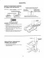
FRAMING SQUARE MUST BE TRUE.
Check its accuracy as illustrated below.
TOOLS
'['
.I,
COMBINATION
MEDIUM
SCREWDRIVER
NEEDED
_ ....
•
I f'
],
I,'I.
I
•
DRAW LIGHT
LINE ON BOARD
'1"
I'
,
STRAIGHT EDGE OF
BOARD 3/4" THICK-THIS EDGE MUST BE
ALONG THIS EDGE _.
,
?',_
PERFECTLY
f,÷_ •
STRAIGHT
SQUARE
8-INCH ADJUSTABLE
WRENCH
SHOULD
BE NO GAP
OR OVERLAP
SQUARE
IS FLIPPED
OVER
WHEN
IN DOTTED
POSITION
COLUMN
ASSEMBLY
8mm DIA. x 20mm LONG BOLT
ASSEMBLY
OF BASE/COLUMN
1. Position base on floor. Remove protective covering
and discard.
2. Remove protective sleeve from column tube and
discard. Place column assembly on base, and align
holes in column support with holes in base.
3. Locate three (3) 8ram Dia. x 20ram long bolts
among loose parts bag.
4. Install a bolt in each hole through column support
and base and tighten with adjustable wrench.
BASE
COLUMN
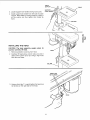
TABLE/SUPPOR
ASSEMBLY
INSTALLATION
OF TABLE/SUPPORT
ASSEMBLY AND HARDWARE
1. Locate table/support assembly
2, Slide table/support assembly onto column. Position
directly above base.
BASE
10
TABLE
SUPPORT
TABLE
.
Locate support lock handle among loose parts.
4. Install support lock handle from left side into table
support. Raise table to working height by sliding it
on the column and then tighten lock handle by
hand.
COLUMN
-_:z:
iNSTALLiNG
THE HEAD
CAUTION: The head assembly weighs about
pounds. Carefully lift head.
1, Remove protective covering from head,
45
2. Carefully lift head above column tube and slide it
down on the column as far as it will go, Align head
with table and base.
COLUMN
HEAD LOCK
SET SCREWS
3. Using a 4mm Hex "L" wrench tighten the head lock
set screws on the right side of the head.
HEAD
11
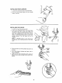
iNSTALLiNG
FEED HANDLES
!_ Locate three (3) feed handles among Iooseparts.
2
Screw the feed handles
hotes in the hub.
iNSTALLING
THE
tightly
into the threaded
CHUCK
1, Locate the chuck among loose parts.
2, Clean out the TAPERED HOLE in the chuck; clean
the spindle nose with a clean cloth. Make sure
there are no foreign particles sticking to the surfaces. The slightest piece of dirt on the spindle
nose or in the chuck will prevent the chuck from
seating
properly,
This will cause the drill to
"wobble."
NOTE:
tremely
cloth,
If TAPERED
HOLE in the chuck is exdirty, use a cleaning solvent on the clean
3. Push the chuck
it will go.
up on the spindle
4: Turn chuck sleeve
chuck completely.
clockwise
,/
nose as far as
and open
___SPINDLE
NOSE
CHUCK
SLEEVE
jaws in
5. Lightly tap the nose of the chuck with a piece of
wood to insure proper seating of the chuck on the
spindle,
12
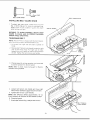
5ram
BELT
GUARD
iNSTALLING
DIA.
x 12ram
SCREW
LONG
KNOB
BELT
BELT
GUARD
GUARD
KNOB
KNOB
1, To attach belt guard knob, locate knob and 5mm
Dia x 12ram _ong pan hd screw in toose parts bag.
Insta!! screw in hote iocated in guard and attach
knob turning until tight.
PAN
HD. SCREW
WARNING:
TO AVOID POSSIBLE
iNJURY KEEP
GUARD
IN PLACE AND iN PROPER
WORKING
ORDER WHILE OPERATING.
TENSIONING
BELT
NOTE: The Drill Press is shipped with the bett instaited,
but it should be properiy tensioned before use
1, Lift guard
hinge,
from
right side
and leave
opened
t-e8
on
I BELT
'TENSION
LOCK
HANDLE
2. Release Belt Tension Lock Handle _ocated on right
side of Drill Press head. Puil right side of motor
toward front of driit press to refieve spring tension
on belt. Tighten the belt tension lock handIe,
(:::
._o
f.,,#)
1:::
3. Choose speed for drilling operation, and move belt
to correct position for desired speed.
NOTE: Refer to chart inside
mended Drilling Speeds.
be}t guard
for Recom-
4. Loosen belt tension lock handle and move right
side of motor rearward to apply tension to the belt,
5. Tighten Belt Tension Lock Handles.
NOTE: Belt SHOULD deflect approximately
thumb pressure at mid-point of belt between
t/2" by
pulleys.
6. Close belt guard,
7, If belt slips while drilling,
readjust
belt tension.
I
13
ADJUSTING
HEAD
THE
TABLE
SQUARE
TO
NOTE: The combination square must be "true." See
the beginning of the "Assembly" section for a method
to check four square.
1. Insert precision round steel rod approximately 3"
tong into chuck and tighten.
2. With table raised to working height and locked on
column, place combination square flat on table beside rod.
COMBINATION
SQUARE
3. If an adjustment is necessary, loosen the table
bevel lock bolt with adjustable wrench. (This adjustment is located under the table).
4. Align the table square to the rod by tilting table.
5. Retighten table bevel lock bolt.
TABLE
TABLE
LOCK
14
BEVEL
BOLT
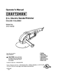
getting
to
press
know
1
BELT
GUARD
/
15
FEED
HANDLE
2
19
ON-OFF
BELTTENSION
HANDLE
SWITCH
LOCK
3
HEAD LOCK
SCREWS
FEED SPRING
ADJUSTMENT
16
4
CHUCK
FEED
SPRING
SET
TABLE
SUPPORT
9
DEPTH
POINTER
14
TABLE
18
STOP
NUTS
COLUMN
COLUMN
SUPPORT
_
IO..
o.__--_
_6
7
' BASE
10
DEPTH
FEED
6
SUPPORT
STOP
SCALE
ROD
SPINDLE
ASSEMBLY
OF DRILL PRESS
13
LOCK
TABLE
HANDLE
BEVEL
..,,p._......._._ SPLINES
(GROOVES)
LOCK
12
BEVEL
SCALE
TABLE REMOVED
FOR CLARITY
-,.----CHUCK
KEY
20
15
___..._
CHUCK
ThisDrillPresshas3 speedsaslistedbelow:
620RPM
! 300RPM
31OORPM
Seeinsideofbeltguardforspecificplacement
ofbelts
onpulleys.
SPINDLE
t3.
2. BELT TENSION LOCK HANDLE ... Tightening
handle locks motor bracket support to maintain correct belt distance and tension.
3. HEAD LOCK :SET SCREWS...
Locks the head
to the column. ALWAYS have them locked in place
while operating the drill press.
14. TABLE...
Provides working surface to suoport
workpiece.
15. FEED HANDLE...
For moving the chuck up or
down. One or two of the handles may be removed
if necessary whenever
the workpiece
is of such
unusual shape that it interferes with the handles,
4, TABLE SUPPORT ... Rides on column to support
table.
16. CHUCK...
accessory
5. COLUMN SUPPORT . . . Supports column and
provides mounting holes for column to base.
6. SUPPORT LOCK HANDLE...
Tightening locks
table support to column. Always have it locked in
place while operating the Drill Press.
17. FEED STOP ROD...
Holds stop nuts for drilling
to specific depths.
t8. STOP NUTS...
Limits the downward movement
of the quill at any desired point within its t_avel,
and prevents the pointer from moving upward.
7. BASE...
Supports Drill Press. For additional stability, holes are provided in base to bolt Drill Press
to bench (See "Additional Safety Instructions for
Drill Presses.")
19. "ON-OFF
SWITCH...
Has locking feature. THIS
FEATURE
IS INTENDED
TO PREVENT
UNAUTHORIZED
AND POSSIBLE
HAZARDOUS
USE
BY CHILDREN
AND OTHERS.
8. SPRING CAP...
spring tension.
20. CHUCK KEY .
which will "pop"
of it, This action
ing of the chuck
is turned "ON".
substitute, order
9. DEPTH POINTER...
Indicates drilling depth and
is located between stop nuts.
10. DEPTH SCALE . .. Shows depth of hole being
drilled in inches and millimeters.
BEVEL LOCK...
from O_-45 °.
BN R.P.M.
1, BELT GUARD .... Covers pulleys and belt during
operation of drill press.
Provides means to adjust quill
TABLE
position
SPEEDS
Holds drill bit or other recommended
to perform desired operations.
. . It is a self-ejecting
chuck key
out of the chuck when you let go
is designed to help prevent throwkey from the chuck when power
Do not use any other key as a
a new one if damaged or lost.
21. BELT TENSION...
Belt" (Page 13).
11. COLUMN...
Connects head, table, and base on
a one-piece tube for easy alignment and movement.
Locks the table in any
Refer to section
"Tensioning
22. DRILLING SPEED...
Can be changed by placing
the belt in any of the STEPS (grooves) in the pulleys. See Spindle Speed chart inside belt guard.
t2. BEVEL SCALE ....
Shows degree table is tilted
for bevel operations. Scale is mounted on table
support. It if to be used for quick reference where
accuracy _snot critical.
To determine
the approximate
the table inside the belt guard.
16
drilling
speed,
refer to
Insert KEY into switch.
NOTE: Key is made of yellow piestico
1
To turn drill ON . . .
Insert finger under switch
To turn drill OFF.,.
lever and pull.
Push lever in.
C
o
In an emergency;..
, the drill bit BINDS...
STALLS
•.. STOPS ., . or tends to tear the workpiece loose
•.. you can QUICKLY turn the drill OFF by hitting the
switch with the palm of your hand.
To lock switch in OFF position..,
hoFd switch IN with
one hand.. , REMOVE key with other hand.
WARNING: FOR YOUR OWN SAFETY, ALWAYS
LOCK THE SWITCH "OFF" WHEN DRILL PRESS IS
NOT IN USE...
REMOVE KEY AND KEEP IT IN A
SAFE PLACE...
ALSO...
IN THE EVENT OF A
POWER FAILURE (ALL OF YOUR LIGHTS GO OUT)
OR
BLOWN
FUSE
OR TRIPPED
CIRCUIT
BREAKER, TURN SWITCH OFF . • • LOCK IT AND
REMOVE THE KEY. THIS WILL PREVENT THE
DRILL PRESS FROM STARTING UP AGAIN WHEN
THE POWER COMES BACK ON.
17
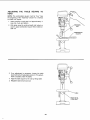
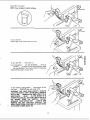
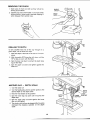
REMOVING
THE CHUCK
SLEEVE
1. Open jaws of chuck as wide as they will go by
turning chuck sleeve.
2. Carefully tap chuck with mallet in one hand while
holding chuck in other hand to prevent dropping it
when released from spindle nose,
DRILLING
TO DEPTH
To drill a BLIND hole (not all the way through) to a
given depth, can be done two ways.
DEPTH
STOP
1. Mark the depth of the hole on the side of the workpiece,
2. With the switch OFF bring the drill down until the
TIP or lips are even with the Mark.
3, Spin the lower nut down to contact the depth stop
lug on the Head,
4. Spin the upper nut down and tighten against the
lower nut.
MARK
/
ANOTHER
WAY -- DEPTH
SCALE
1. Turn the switch off.
2. Turn the feedhand_e until the pointer points to the
desired depth on the depth scale.
DEPTH
SCALE
3. Hold the feed handle at this position.
DEPTH,
STOP
4. Spin the lower stop nut down until it touches the
depth stop.
5. Spin the upper stop nut down against the lower
stop nut and tighten.
6. The chuck ordrill will now be stopped after traveling
downward the distance selected on the depth
scale.
18
UPPER
STOP
LOWER
STOP NUT
NUT
basic dr!IS press operation
Follow the following instructions for operating
press to get the best results and to minimize
hood of personal injury.
--
Never do any work "FREE HAND" (handholding workpiece
rather than supporting it
on the table), except when polishing.
-- Securely !ock Head and Support to Column,
Table Arm to support, and Table to Table
Arm before operating drill press.
-- Never move the Head or Table while the
toot is running.
-- Before starting the operation, jog the motor
switch to make sure the drill or other cutting
toot does not wobble or cause vibration.
-- If a workpiece overhangs the table such that
it witt fall or tip if not held, clamp it to the
table or provide auxiliary support.
-- Use fixtures
for unusual
operations
to
adequately
hold, guide and position workpiece.
-- Use the SPINDLE
SPEED recommended
for the specific operation and workpiece material--check
the panel inside the guard
cover for drilling
information;
for accessories, refer to the instructions provided with
the accessories.
f. Never climb on the drill press Table, it could
break or put! the entire drill press down on you.
g. Turn the motor Switch Off and put away the
Switch Key when leaving the drill press.
h. To avoid injury from thrown work or toot contact,
do NOT perform layout, assembly,
or setup
work on the table while the cutting tool is rotating.
your drill
the likeli-
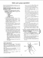
WARNING:
FOR YOUR OWN SAFETY,
ALWAYS
OBSERVE THE SAFETY PRECAUTmONS HERE AND
ON PAGES 2, 3, AND 4.
!.
Protection:
Eyes, Hands,
Face, Ears and Body
WARNING:
TO AVOID BEING
THE SPINNING TOOL -1. Do
----2. Do
PULLED
iNTO
NOT wear:
gloves
necktie
loose clothing
jewelry
tie back long hair
a. If any part of your drill press is missing, malfunctioning, has been damaged or broken..,
such
as the motor switch, or other operating control,
a safety device or the power cord . . . cease
operating
immediately
until the particular part
is properly repaired or replaced.
b. Never place your fingers in a position where
they could contact the drill or other cutting tool
if the workpiece should unexpectedly
shift or
your hand should slip.
c. To avoid injury from parts thrown by the spring,
follow instructions exactly as given and shown
in adjusting spring tension of quill.
d. To prevent the workpiece from being torn from
your hands, spinning of the tool, shattering the
toot or being thrown, always properly support
your work so it won't shift or bind on the tool:
-- Always position BACKUP MATERIAL (use
beneath the workpiece)
to contact the left
side of the column.
-- Whenever
possible,
position
the WORKPIECE to contact the left side of the column-if
it is too short or the table is tilted,
clamp solidly to the table. Use table slots or
clamping ledge around the outside edge of
the table.
-- When using a drill press VICE, always fasten
it to a table,
2. Use only accessories
designed for this drill
o_
€_
_t,-o.- _o
press to avoid serious
injury from thrown broken parts or work pieces.
a. Holesaws must NEVER be operated on this drill
._.oo
press at a speed greater than 400 RPM
b. Drum sanders must NEVER be operated on
this drill press at a speed greater than 1800
RPM.
c, Do not install or use any drill that exceeds 7" in
length or extends 6" below the chuck jaws. They
can suddenly bend outward or break.
d. Do not use wire wheels, router bits, shaper cutters, circle (fly) cutters or rotary planers on the
drill press.
=n
m
iNSTALLING
DRILLS
Insert drill into chuck far enough to obtain
GRIPPING
of the CHUCK JAWS . • . the
approx. 1" long. When using a small drill do
it so far that the jaws touch the flutes (spiral
of the drill.
maximum
jaws are
not insert
grooves)
:HUCK
Make sure that the drill is CENTERED
in the chuck
before tightening the chuck with the key.
Tighten the drill sufficiently, so that it does not SLIP
while drilling.
Turn the chuck
key clockwise
to tighten--counterclockwise
to loosen.
JAWS
19
KEY
_.=
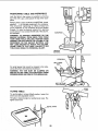
POSITiONiNG
TABLE AND WORKPIECE
Lock the table to the column in a position so that the
tip of the dritl is just a little above the top of the workpiece.
Always place a piece of BACK-UP MATERIAL (wood,
plywood...)
on the table underneath the workpiece.
This will prevent "splintering" or making a heavy burr
on the underside on the workpiece as the drill breaks
through. To keep the backup material from spinning
out of control, it must contact the left side of the column,
as illustrated.
WARNING: TO PREVENT WORKPIECE OR THE
BACKUP MATERIAL FROM BEING TORN FROM
YOUR HAND WHILE DRiLLiNG, POSITION THEM
AGAINST THE LEFT SiDE OF THE COLUMN. IF THE
WORKPIECE OR THE BACKUP MATERIAL ARE
NOT LONG ENOUGH TO REACH THE COLUMN,
CLAMP THEM TO THE TABLE. FAILURE TO DO
THIS COULD RESULT IN PERSONAL INJURY.
WORKPIECE
\
BACK-UP
MATERIAL
For small pieces that cannot be clamped to the table.
use a drill press vise (Optional accessory).
WARNING: THE VISE MUST BE CLAMPED OR
BOLTED TO THE TABLE TO AVOID INJURY FROM
SPINNING WORK AND VISE OR TOOL BREAKAGE.
BOLT OR CLAMP
VICE SECURELY
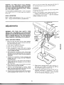
TILTING
BEVEL
LOCK
TABLE
To use the table in a bevel (tilted) position, loosen the
bevel lock with adjustable wrench.
Tilt table to desired angle by reading bevel scale. Retighten bevel lock.
BEVEL
2O
SCALE
Before turning the switch ON, bring the drill down to
the workpiece lining it up with the hole location.
WARNING:
TO AVOID iNJURY FROM SPiNNiNG
WORK OR TOOL BREAKAGE,
ALWAYS
CLAMP
WORKPmECE AND BACKUP MATERIAL
SECURELY
TO TABLE
BEFORE
OPERATING
DRILL
PRESS
WITH THE TABLE TILTED.
FEEDING
Pull down on the feed handles
to allow the drill to cut.
To return table to original position: loosen the bevel
lock, tilt table back to 0 ° on bevel scale, and retighten
bevel lock.
with only enough
effort
Feeding TOO SLOWLY might cause the dritl to burn
•.. Feeding TOO RAPIDLY might stop the motor...
cause the belt or drill to SLIP . . . tear the workpiece
LOOSE or BREAK the drill bit.
HOLE LOCATION
Make a DENT in the workpiece where you want the
hole.., using a CENTER PUNCH ora SHARP NAIL.
SPRING
CAP
NOTCH
adjustments
BOSS
WARNING:
FOR
YOUR
OWN
SAFETY
TURN
SWITCH "OFF" AND REMOVE PLUG FROM POWER
SOURCE OUTLET BEFORE MAKING ANY ADJUSTMENTS. TO AVOID iNJURY FROM THROWN
PARTS
DUE TO SPRING
RELEASE,
FOLLOW
INSTRUCTIONS CAREFULLY
AND WEAR EYE GOGGLES.
QUILL
RETURN
\
JAM
NUT
(OUTER)
STANDARD
NUT
SPRING
(INNER)
1. Move the stop nuts down to their lowest position
and lock in place with wrench to prevent quill dropping while tensioning spring,
2. Lower table for additional clearance.
3. Work from left side of Drill Press.
4. Place screwdriver in lower front notch of spring
cap, and hold it in place while loosening and removing jam [outer] nut only.
5. With screwdriver remaining in notch, loosen large
standard [inner] nut (approximately 1/8"),until notch
disengages from boss on head. DO NOT REMOVE
THIS NUT.
6. Carefully turn screwdriver counter clockwise and
engage next notch in boss. DO NOT REMOVE
SCREWDRIVER.
7. Tighten standard nut with wrench only enough to
engage boss. Do not overtighten as this will restrict
quill movement.
8. Move stop nuts to upper most position and check
tension while turning feed handles.
1t.
9. If there is not enough tension on spring, repeat
steps 4-8 moving only ONE notch each time and
checking tension after EACH repetition.
10. Proper tension is achieved when quill returns gently
to full up position when released from 3/4" depth.
When there is enough tension after checking,
replace jam nut and tighten to standard nut, BUT do
not overtighten
against standard
nut.
12. Check quill while feeding
to have smooth
and un-
restricted
movement.
If movement
is too tight,
loosen jam nut and SLIGHTLY
loosen standard
nut until unrestricted.
Retighten
jam nut.
2!
maintenance
WARNING
FOR YOUR OWN SAFETY, TURN
SWITCH "OFF" AND REMOVE PLUG FROM POWER
SOURCE OUTLET BEFORE MAINTAINING OR LUBRiCATiNG YOUR DRILL PRESS.
MOTOR
CORD
C....
T
BLACK
Frequently blow out any dust that may accumulate inside the motor.
A coat of furniture-type paste wax applied to the table
and column will help to keep the surfaces clean.
POWER
WARNING: TO AVOID SHOCK OR FiRE HAZARD,
iF THE POWER CORD iS WORN OR CUT, OR DAMAGED iN ANY WAY, HAVE IT REPLACED IMMEDIATELY.
CORD
Wiring
Diagram
.,_.._._._
SPINDLE ASSEMBLY
OF DRILL PRESS
lubrication
SPLINES
RACK
All of the BALL BEARINGS are packed with grease at
the factory. They require no further lubrication.
Periodically lubricate the SPLINES (grooves)
spindle, and the RACK (teeth of the quill).
"-----
in the
" _"_--"-
Sears Recommends
Drill Bits .........................
See
Hold-Down and Guide ..................
Drill Press Vises ...................
See
5 pc. Stop Collar Set ...............
See
Sanding Drums ................
9-2497 15 Piece Drum Sanding Kit .........
See
(TEETH)
the Following
Catalog
9-2457
Catalog
Catalog
9-2498
Catalog
CHUCK
Accessories
Clamping Kit ......................
See Catalog
Buffing Wheels up to 4" dia. max ......
See Catalog
Power Tool Know-How Handbook ........
9-29117
Sears may recommend
the manual.
other
See your nearest Sears
for other accessories.
store
accessories
or Catalog
not listed in
department
Do not use anyaccessory
unless you have received
read complete instructions
for its use.
22
and
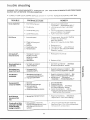
trouble
shooting
WARNSNG: FOR YOUR OWN SAFETY
TURN SWITCH
SOURCE OUTLET BEFORE "TROUBLE SHOOTING.
® CONSULT
YOUR LOCAL
SEARS
TROUBLE
Noisy Operation
SERVICE
PROBABLE
"OFF"
CENTER
IF FOR ANY REASON
1, Incorrect betttension,
WILL
NOT RUN
4. Loose motor pulley,
1. incorrect
I.
speed.
1,
.
POWER
Change speed. See section "Getting
To Know Your DriI1 Press"...
DRILLING SPEED.
2, Retract drill frequently to clear chips.
3, Resharpen drift.
4. Feed fast enough
,aitow drill to cut.
5 Lubricate drilt. See"Basic Drill Press
Operation" section,
4. Feedingtoo S!OWr
5. Not lubricated.
Hard grain in wood or
lengths of cutting
tips and/or angles
not equal,
Bent drill bit,
Wood splinters on
underside.
1. No "back-up material"
Workpiece torn
loose from hand.
1,
Excessive drill
runout or wobble.
FROM
Adjust tension, See section
ASSEMBLY-TENSIONING
BELT."
2. Lubricate spindle, See "Lubrication"
section.
3 Checking tightness of retaining nut on
pulley, and tighten if necessary,
4, Tighten setscrews in pulleys,
2. Chips not coming out
of hole.
3. Dull Drill.
Drill Binds in
workpiece.
MOTOR
PLUG
I,
3. Loose spindle pulley,
Drill leads off...
hole not round.
REMOVE
REMEDY
CAUSE
2. Dry Spindle,
Drill Burns
AND ALWAYS
1
Resharpendritlcorrectiy,
2.
Replace dritt biL
t. Use "back-up material"..
See Basic
Drill Press Operation" section.
under workpiece,
Not supported or
clamped properly.
t,
Support workpiece or clamp it... See
"Basic Drill Press Operation" section.
E
6€}
Workpiece pinching drill
or excessive feed pressure.
2. Improper belt tension,
1. Support workpiece or clamp it,.. See
"Basic Drit! Press Operation" section.
See section
2. Adjust tension,..
"ASSEMBLY--TENSiONING
BELT."
Bent drill°
2. Worn spindle bearings.
3. Drill not properly
installed in chuck.
4. Chuck not properly installed.
1. Use a straight drill,
2. Replace bearings,
See"Basic
3. install dri{l properly.,
Drill Press Operation" section.
4,
InstalI chuck properly.,
refer to
"Unpacking and Assembly Instructions
... iNSTALLING THE CHUCK."
1.
1,
Quill Returns
too slow ortoe
fast.
t, Spring has improper
Chuck will not stay
attached to spindle
it falls offwhen
trying to install it.
1. Dirty, grease, or oii on the
tapered inside surface of chuckor on the spindles tapered
surface.
Adjust spring tension...
See section.
"Adjustments--Quill
Return Spring,"
tension,
23
1.
Using a ho_Jseho!d detergent-clean
the
tapered su.'fface of the chuck and spindie to
remove a!i dirt. grease and oil
O
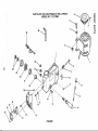
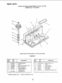
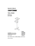
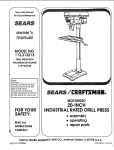
PARTS
LIST FOR CRAFTSMAN
8" DRILL PRESS
MODEL NO. 113.213080
='O
mo
"O
34
33
1
/
\
7
3O
29
28
27
26
16
24
17
18
20
15
19
FIGURE
1
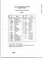
PARTS
LiST FOR CRAFTSMAN
8" DRILL PRESS
MODEL NO. 113.213080
Always order by Part Number--Not
FIGURE
Key J
No. I
r,o
¢jn
Part
No.
Description
2
3
4
5
6
817771
817449
STD551031
STD835025
817427
817391-3
7
8
9
10
11
817420
817445
817444
817421
817391-2
12
13
14
15
16
17
18
19
20
817439
817438
817409
STD840812
817442
STD852005
816755-4
817770
816755-3
Head w/Roll Pin & Trim
Nut-Lock M8 x 1.25-8
*Washer-5/16 x 11/16x 1/16
* Screw-Hex M8 x 1.25-25
• Pulley-Motor
Screw-Hex Soc. Set
M6 x 1.0-6
oMotor
Stop-Motor
Spring-Motor Stop
Knob-Motor Adjusting
Screw-Hex Soc. Set
M8 x 1.25-8
Knob
Rod
Shaft-Pinion
*Nut-Hex M8 x 1.25
Screw-Fit. Sit. Set M8 x 1.25
* Lockwasher-Ext. 5mm
Screw-Pan Hd. M5 x 0.8-8
Box-Switch w/Depth Scale
Screw-Pan Cr. M5 x 0,8-12
by Key Number
1
t_
Key
No.
Part
No.
21
22
816113
817357
23
24
25
26
27
28
29
30
31
32
33
34
817422
815863
STD375008
817406
817443
817415
817416
STD541137
STD841015
817419
817329-1
813317-7
507871
507870
SP5184
Description
Switch-Locking
Screw_Self tap. pan
hd. M4x16-8
Cover-Switch Plate
Key-Switch
*Connector-Wire
seat-Spring
Retainer-Spring
Spring-Tension
Cap-Spring
* Nut-Hex 3/8-24
*NutHexM10xl.5
Pointer
Cord-Power
Wrench Hex "L" 4ram
Bag of Loose Parts
(Not Illustrated)
Box of Loose Parts
(Not Illustrated)
Owners Manual
(Not Illustrated)
* Standard Hardware Item -- May Be Purchased Locally.
e Any attempt to repair this motor may create a HAZARD unless repair is done by a qualfied service technician,
Repair service is available at your nearest Sears Store.
RepairPa s
repair parts
PARTS LiST FOR CRAFTSMAN 8" DR_LL PRESS
MODEL NO. 113.213080
2
\
14
Always order by Part Number--Not
FIGURE
Key
No.
Part
No.
1
2
817451-1
817325
5
6
816755-3
817428
817779
817358
7
8!7453-1
Bushing-Rubber
Knob
Screw-Pan Hd, M5 x 0.8-12
Belt-"V" 5/16 x 26
Guard w/Labels
Screw-Washer Hd.
M6x1,0-16
Ring Retaining
* Standard Hardware Item -
2
K_y
No. ,
Description
May Be Purchased Locally
26
by Key Number
Part
Ne.
8
STD315235
9
10
11
12
13
14
817408
817407
817426
817440
63418
816755-6
Description
*Bearing-Ball 17ram
Spacer
Insert-Pulley
Pulley-Spindle
Nut-Pulley
Ctamp Cord
Screw Pan Hd. M5 x 0.8-8
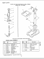
repair parts
PARTS
I
LIST
FOR CRAFTSMAN
8" DRILL
MODEL
NO. 113.213080
PRESS
1
fl
2
j2
Always order by Part Number--Not
FIGURE
3 QUILL
by Key Number
FIGURE
ASSEMBLY
4
n
Key
No.
Part
No.
1
2
3
4
5
6
7
8
9
10
11
12
817413
STD3152t5
817411
816755
817414
817453
817410
817340-1
817339-1
STD840610
STD840508
817418
Description
Gasket-Quill
* Bearing-Ball 12ram
Tube-Quill
Screw-Pan M5 x 0.8-20
Collar-Stop
Ring-Retaining
Shaft-Spindle
Chuck
Key-Chuck
* Nut-Hex M6 x 1.0
*Nut-Hex M5 x 0.8
Rod-Stop
* Standard Hardware Item -
May Be Purchased Locally.
27
Key
No.
Part
No.
1
2
3
4
5
6
817773
817290
817433
817431
817434
STD835020
7
8
817447
817437
Description
Support-Table w/Sca_e
Support-Lock Handle
Tube-Column
Base
Support-Column
* Screw-Hex Hd.
M8 x 1.25-20
Screw-Hex Hd. 1/2-12 x 7/8
Table
f
L
i.i.
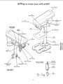
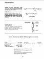
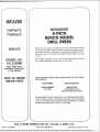
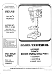
Now that you have purchased
your 8-inch Drill Press, should
a need ever exist for repair parts or service, simply contact
any Sears Service Center and most Sears, Roebuck and Co.
stores. Be sure to provide all pertinent facts when you call
or visit.
SERVICE
The model
on a plate
MODEL NO.
!t3.2t3080
number
attached
of your 8-inch Drill Press will be found
to the rear of the head.
DREL PRESS WITH
MAXIMUM
DEVELOPED
I/3 HP MOTOR
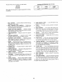
HOW TO ORDER
REPAIR PARTS
WHEN ORDERING REPAIR PARTS,ALWAYS GIVE THE FOLLOWING
INFORMATION:
PARTNUMBER
PARTDESCRIPTION
MODEL NUMBER
113.213080
NAME OF ITEM
MOTORIZED 8-INCH
BENCH MODEL DRILLPRESS
All parts listed may be ordered from any Sears Service Center
and most Sears stores. If the parts you need are not stocked
locally, your order wi!l be electronically
transmitted to a Sears
Repair Parts Distribution Center for handling.
J
J
Sold by SEARS, ROEBUCK AND CO., Chicago,
Part No. SP5184
Form
No. SP5184-3
IL 60684
U.S.A.
Printed
in Taiwan
9/;90