1
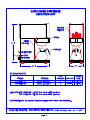
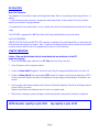
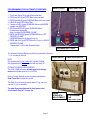
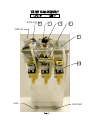
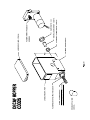
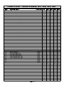
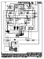
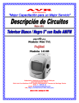
INSTALLATION
Water Inlet Connection:
This equipment is to be installed to comply with the applicable Federal, State, or local plumbing codes having jurisdiction. In
addition:
1. A quick disconnect water connection or enough extra coiled tubing (at least 2 times the depth of the unit) so that the
machine can be moved for cleaning underneath.
2. An approved back flow prevention device, such as a double check valve to be installed between the machine and the water
supply.
The JAVA2-QB-D is equipped with a 1/4" Flare Water Inlet Fitting, located behind the unit near the bottom.
HIGHLY RECOMMENDED:
A WATER SHUT-OFF VALVE and A WATER FILTER, preferably a combination Charcoal/Phosphate Filter, to remove odors and
inhibit lime and scale build up in the machine. Note: In areas with extremely hard water, a water softener must be installed
in order to prevent a malfunctioning of the equipment and in order not to void the warranty.
STARTUP PROCEDURE
Caution: Make sure that the Heater Switch, located behind unit near the bottom, is in the OFF
(toggle down) position.
1. Connect the 1/4" Dia. copper waterline to the 1/4" flare water inlet fitting of the valve.
2. Connect the power cord into a proper receptacle.
3. Activate the Power Switch (Toggle Up). The tank will start filling. Allow approximately 5 minutes for the tank to fill.
4. Activate the Heater Switch. Allow approximately 20-45 minutes for the water to reach a preset temperature of 200°F.
The heat up time will depend on the water inlet temperature, the input voltage, and the wattage of the elements in the
machine.
5. Place cup under nozzle and press dispense switch, button will light while dispensing. The machine will dispense water at
the rate of 1.3 oz. per second.
Repeat it several times for each dispense switch to check for consistent output.
6. While the tank is heating up, remove the hoppers, load them with products and reposition them back in the machine.
NOTE: Decanter capacity is up to 54 OZ.
Cup capacity is up to 12 OZ.
Page 3
PROGRAMMING FOR AUTOMATIC DISPENSE
(See Door diagram)
READY LIGHT
HEATING LIGHT
1.
2.
3.
4.
5.
Turn Power Switch ON (toggle switch inside door).
PRESS and HOLD [red] STOP Button with one hand.
PRESS and HOLD [green] DISPENSE Button with other hand.
RELEASE [red] STOP Button ONLY.
Continue to HOLD [green] DISPENSE Button until BUZZER
sounds, then RELEASE.
6. PRESS and RELEASE [green] DISPENSE Button.
Product begins dispensing.
When it reaches the “DESIRED VOLUME”,
7. PRESS and RELEASE [green] DISPENSE Button to SET
“DESIRED VOLUME”.
DISPENSE Button can be jogged to top off.
8. PRESS and HOLD [red] STOP Button for 5 Secs. to LOCK IN
“DESIRED VOLUME”.
Repeat steps 1 to 8 for each Dispense Button.
DISPENSE BUTTONS
The Automatic Dispense Buttons are factory programmed to dispense
1.3 oz. of water per second.
POWER SWITCH
NOTE:
Set programming for Cup Volume with cup shelf “DOWN”.
Set programming for Decanter Volume with cup shelf “UP”.
RINSE/ SERVE SWITCH
PRODUCT STRENGTH ADJUSTMENTS:
The JAVA 2-QBD units have variable speed control auger
motors with variable speed of 10 to 30 RPM.
Drink or Product Strength can be changed by adjusting the
Gram Throw Dial on inside door panel.
The Gram Throw is factory preset at approx. 2.2 gr. per 8 oz.
cup and 15.0 gr. per decanter.
The water flow rate adjustment for the dispense valve
should remain fixed at 1.3 oz per sec.
DRINK
STRENGTH
ADJUSTMENT
Page 4
PROGRAMMI
NG
INSTRUCTION
CLEANING AND SANITIZING:
SANITIZING: All food dispensing units should be sanitized periodically. All parts to be sanitized must be cleaned first.
To prepare a sanitizing solution: ADD 2 TSP. OF LIQUID CLOROX BLEACH (5.25% CONCENTRATION) TO 1 GALLON OF
WATER AT ROOM TEMPERATURE (70°F - 90°F).
Soak all parts for a minimum of 3 min. in the sanitizing solution. Note: Always start with an unopened bottle of Clorox
Bleach since the solution from an opened bottle has a short life span.
Let all sanitized parts drain and dry naturally. DO NOT WIPE THEM DRY. Before using the sanitized unit (or parts) with
foodstuffs, rinse all parts thoroughly with water.
CARE FOR STAINLESS STEEL:
STAINLESS STEEL surfaces, that comes in contact with food substances, MUST BE CLEANED EVERY DAY.
WHEN CLEANING STAINLESS STEEL, ONLY A PH NEUTRAL CLEANER IS TO BE USED.
Use nylon or brass brushes (not steel wire brushes) for removing food deposit.
Many food products contain acids, alkalis, or other substances, which corrode Stainless Steel.
RECOMMENDED DAILY CLEANING AND MAINTENANCE
1. Wash cup shelf and warmer dish with dish detergent.
Rinse Chambers:
Flip Toggle SWITCH to RINSE position and press DISPENSE BUTTON.
When done, flip toggle switch back to SERVE position.
Remove and refill Hoppers.
Note: When removing hoppers, turn PRODUCT GUIDE UP to reduce spillage,
return to down position after re-inserting hoppers.
CLEAN HOPPERS (once a week)
1. Turn the product guide up, and remove hoppers.
2. Empty out Hoppers.
3. Pull off Product Guide.
4. Wash parts with dish detergent.
5. Rinse, dry, and re-assemble parts.
CLEAN DISPENSE CHAMBERS (once a week)
1. Twist CW and pull off STEAM DEFLECTOR.
2. Pull off DISPENSE CHAMBER.
3. Wash components with dish detergent.
4. Rinse, dry, and re-assemble parts.
Page 5
30
25
11
24
9
17
28
WATER LEVEL 32
1
4
2
OVERFLOW
3
18
DRAIN
WATER INLET
PRODUCT GUIDE
CD70A
WIRE AUGER CD74A
(17mm DIA, 12.0mm PITCH)
AUGER BUSHING FRONT CD306
LABEL NA38A REF
HOPPER BASE CD140
NUT CD278 [2]
BEVELLED SOCKET CD271
AUGER BUSHING-BACK CD279
AUGER MOTOR CD151
83 RPM
HOPPER COVER CD106
PARTS LIST : JAVA 2-QB-D, -D1, -D2, -D3, -DC
1
1
2
3
4
5
6
7
8
8
9
9
10
11
12
13
14
14
15
16
17
17
18
18
19
20
21
22
22
23
24
24
25
25
26
27
27
28
29
29
30
31
32
33
34
34
34
35
36
37
HEATER, 1500W, 120V
HEATER, 3500W, 240V
THERMOSTAT
SILICONE GROMMET, 12 mm
HI-LIMIT, 200° CUTOUT
PUSH BUTTON SWITCH (GREEN DISPENSE)
PUSH BUTTON SWITCH (RED STOP)
PUSH BUTTON SWITCH (AMBER HOT WATER)
PILOT LIGHT, GREEN (READY) 120V
PILOT LIGHT, GREEN (READY) 240V
RELAY, 120V
RELAY, 220V (FOR 240 V UNITS)
POTENTIOMETER
SPEED CONTROLLER
TOGGLE SWITCH, DPST (POWER ON-OFF)
TOGGLE SWITCH, SPST (RINSE-SERVE) & (HEATER)
PILOT LIGHT, RED (HEATING) 120V
PILOT LIGHT, RED (HEATING) 240V
LATCH
HOPPER
WATER INLET VALVE 110V
WATER INLET VALVE 220V
DISPENSE VALVE
240 VOLT COIL F/DISPENSE VALVE
STEAM CAP
MIXING BOWL
SOCKET, MIXING BOWL
SPOUT ASSEMBLY
SPOUT ASSEMBLY
SPOUT ASSEMBLY
TEACH-ME TIMER DUAL
TEACH-ME TIMER SINGLE
LEVEL CONTROL DUAL 120V
LEVEL CONTROL DUAL 240V
BLOWER HOSE (1" DIA)
BLOWER/ FAN 120V
BLOWER/ FAN 240V
TRANSFORMER, 24V
WARMER ELEMENT, 120V, 60W
WARMER ELEMENT, 220V, 80W
AUGER MOTOR 24V, 83 RPM
PRODUCT GUIDE, LEFT
DUAL LEVEL PROBE ASSEMBLY
POWER CORD 120V
POWER CORD 220V
FUNNEL
FUNNEL
HOPPER GUIDE
WARMER SWITCH, RED
SHELF SWITCH
G194A
G197A
L681A
M461A
L656A
L455A
L574A
L457A
CH112
CH260
B138A
B172A
L557A
L556A
L299A
L069A
32004
CD55A
M705A
CD325
CD257
CD258
L467A
CF38A
CD61A
CD137
CD67A
M934Q
M935Q
M864Q
L726A
L576A
L690A
L706A
CD369
CD56A
CD166
CF29A
G386A
G110A
CD151
CD70A
K659Q
C032A
CH50A
V274Q
V270Q
SL30A
L217A
56039
1
1
1
7
1
2
1
1
1
1
4
4
2
2
1
2
1
1
1
2
1
1
2
2
1
1
1
1
_
_
2
_
1
1
1
1
1
2
_
_
2
1
1
1
1
_
1
2
_
1
1
1
1
7
1
2
1
1
1
1
4
4
2
2
1
2
1
1
1
2
1
1
2
2
1
1
1
1
_
_
_
2
1
1
1
1
1
2
1
1
2
1
1
1
1
_
1
2
1
_
1
1
1
7
1
2
1
1
1
1
4
4
2
2
1
2
1
1
1
2
1
1
2
2
1
1
1
1
_
_
2
_
1
1
1
1
1
2
2
2
2
1
1
1
1
_
1
2
2
1
1
1
1
7
1
2
1
1
1
1
4
4
2
2
1
2
1
1
1
2
1
1
2
2
1
1
1
1
_
_
_
2
1
1
1
1
1
2
3
3
2
1
1
1
1
_
1
2
3
_
1
1
1
8
1
2
1
1
1
1
3
3
2
2
1
2
1
1
1
2
1
1
3
3
2
2
2
_
1
1
2
_
1
1
1
1
1
2
_
_
2
2
1
1
1
1
_
2
_
1
TIMER SW
K1
RELAY
3
5
2
4
1
3
DUAL
TIMER
POWER
L1
K2
RELAY
STOP SWITCH
COFFEE
3
5
2
4
1
3
DUAL
TIMER
DOOR UNIT
N
DECAFF
HOT WATER
READY
D.C.
AUGER
MOTOR
.
.
SPEED
CONTROL
RINSE
K2
RELAY
COIL
D.C.
AUGER
MOTOR
HEATING
SPEED
CONTROL
DISPENSE
VALVE
HOT
WATER
VALVE
K1
RELAY
COIL
K4
RED
WATER INLET
VALVE
LIQUID LEVEL CONTROL
K3
BLK
WHT
BLU
WATER LEVEL
PROBES
YEL
GRN
WATER
VACUUM FAN
N
HI-LIMIT
THERMOSTAT
3 PIN CONNECTOR
HEATER SW
WARMER SWITCH
WARMER
OPTIONAL
JE
1:1
E
PROGRAMMING SW. CUP/ DECANTER
L1
N
3
5
2
4
1
3
DUAL
TIMER
POWER
STOP SWITCH
3
K2
RELAY
5
K5a
2
4
1
3
DUAL
TIMER
DOOR UNIT
K1
RELAY
K5b
COFFEE
DECAFF
HOT WATER
READY
D.C.
AUGER
MOTOR
D.C.
AUGER
MOTOR
SPEED
CONTROL
RINSE
HOT
WATER
VALVE
K2
RELAY
COIL
SPEED
CONTROL
DISPENSE
VALVE-1
K1
RELAY
COIL
K4
RED
WATER INLET
VALVE
HEATING
K3
BLK
WHT
BLU
K5 TEMP.
LOCKOUT
YEL
GRN
VACUUM FAN
N
HI-LIMIT
THERMOSTAT
3 PIN
CONNECTOR
WARMER
WARMER
SWITCH
OPTIONAL
WARMER
CUTOUT
SWITCH
HEATER SW
PROGRAMMING SW. CUP/ DECANTER
K1
RELAY
3
5
2
4
1
3
DUAL
TIMER
POWER
STOP SWITCH
K2
RELAY
3
5
2
1
4
3
DUAL
TIMER
DECAFF
HOT WATER
COFFEE
L1
DOOR UNIT
N
READY
D.C.
AUGER
MOTOR
D.C.
AUGER
MOTOR
SPEED
CONTROL
RINSE
HEATING
SPEED
CONTROL
HOT WATER
VALVE
K2
RELAY
COIL
DISPENSE
VALVE- 2
DISPENSE
VALVE-1
K1
RELAY
COIL
RED
K3
BLK
WHT
BLU
WATER INLET
VALVE
YEL
GRN
VACUUM FAN
N
HI-LIMIT
THERMOSTAT
3 PIN
CONNECTOR
WARMER
WARMER
SWITCH
OPTIONAL
WARMER
CUTOUT
SWITCH
HEATER SW
L1
N
3
5
2
4
1
3
TEACH ME
TIMER
POWER
K2
RELAY
STOP SWITCH
COFFEE
3
5
2
4
1
3
TEACH ME
TIMER
DOOR UNIT
K1
RELAY
DECAFF
HOT WATER
READY
D.C.
AUGER
MOTOR
.
.
SPEED
CONTROL
RINSE
K2
RELAY
COIL
D.C.
AUGER
MOTOR
HEATING
SPEED
CONTROL
DISPENSE
VALVE
HOT
WATER
VALVE
K1
RELAY
COIL
K4
RED
WATER INLET
VALVE
LIQUID LEVEL CONTROL
K3
BLK
WHT
BLU
WATER LEVEL
PROBES
YEL
GRN
WATER
VACUUM FAN
N
HI-LIMIT
THERMOSTAT
3 PIN CONNECTOR
HEATER SW
WARMER SWITCH
WARMER
OPTIONAL
M.M.
1:1
A