1
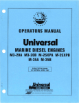
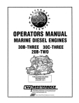
OPERATORS MANUAL
U
rsal
MARINE DIESEL ENGINES
M3-20B M-25XPB M-35B
- ... B -50B
-
.
PUBLICATION 200550
REVISION 2
FEBRUARY 2010
WE5TERBEKE CORPORATION. MYLES STANDISH INDUSTRIAL PARK
150JOHN HANCOCK ROAD, TAUNTON, MA 02780·7319 U.S.A. .
TEl..: (508)823-7871 0 FAX: (508}B84·9688· weBSITE: WWW.WESTERBEIfE.COM
..4JJs!J Member
NaluJlla[ Marille
Manu/acturers Associalioll
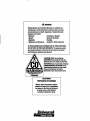
A WARNING
Exhaust gasses contain Carbon Monoxide, an odorless and
colorless gas. Carbon Monoxide Is poisonous and can cause
uncIIIISClousness and death. Symptoms of Carbon Monoxide
expDS1118 can include:
-Dizziness
- Throbbing In Temp/es
-/Iaus8a
- Muscular Twitching
-Headache
- Vomiting
- Weakness and Sleepiness - Inability to Think Coherently
IF YOU OR ANYONE ELSE EXPERIENCE ANY OF THESE SYMPTOMS,
GET BUT INTO THE FRESH AIR IMMEDIATELY. If symptoms persist,
seek medical attention. Shut dllwn the unit and do not restart
until It has been inspected and repaired.
A WARNING DECAL is provided by
WESTERBEKE and should be fixed to a
bulkhead near your engine or generator.
WESTERBEKE also recommends installing
CARBON MONOXIDE DETECTORS In the
/ ~!-!~~lII!Ii!i!IlI!"~~\ Ilving/sleeping quarters of you; vessel.
(,
They are inexpensive and easily
obtainabie at your locai marine store.
.WA RNI NG
Engi!Is - . . CARBON MONOXlDE
AI9'ar""""""" Req.ired
"'.1.-
CALIFORNIA
PROPOSITION 65 WARNING
Marine diesel and gasoline engine
exhaust and some 01 Its constituents
are known to the State 01 Calilornia
to cause cancer, birth delects,
and other reproductive harm.
SAFETY INSTRUCTIONS
PREVENT BURNS - FIRE
Read this safety manual carefully. Most accidents are
caused by failure to follow fundamental rules and precau·
tions. Know when dangerous conditions exist and take the
necessary precautions to protect yourself, your personnel,
and your machinery.
The following safety instructions are in compliance with
the American Boat and Yacht Council (ABYC) standards.
•
Prevent flash fires. Do not smoke or pennit flames or
sparks to occur near the carburetor, fuel line, filter, fuel
pump, or other potential sources of spilled fuel or fuel
vapors. Use a suitable container to catch al1 fuel when
removing the fuel line, carburetor, or fuel filters.
PREVENT B.ECmIC SHOCK
•
Do not operate with a Coast Guard Approved flame
arrester removed. Backfire can cause severe injury or
death.
A
WARNING: Do not touch AC electrical connsetlollS
wfr/IB tlllfl/ilfl Is fUnning, or when connocted to shoro
p__ LBlhBI roltage Is prtlSBnt at thBSIJ connections!
A WARNING: Flro can cause injury or death!
•
Do not operate with the air cleaner/silencer removed.
Backfire can cause severe injury or death.
•
Do not smoke or permit flames or sparks to occur near
the fuel system. Keep the compartment and the
engine/generator clean and free of debris to minimize the
chances of fire. Wipe up all spilled fuel and engine oil.
Be aware -
•
Do not operate this machinery without electrical
enclosures and covers in place.
•
Shut off electrical power before accessing electrical
equipment.
•
•
Use insulated mats whenever working on electrical
equipment.
PREVENT BURNS - EXPLOSION
•
Make sure your clothing and skin are dry, not damp
(particularly shoes) when handling electrical equipment.
•
Remove wristwatch and all jewelry when working on
electrical equipment.
•
Do not connect utility shore power to vessel's AC
circuits, except through a ship-to-shore double throw
transfer switch. Damage to vessel's AC generator may
result if this procedure is not followed.
•
Electrical shock results from handling a charged capacitor. Discharge capacitor by shorting terminals together.
A WARNING: Explosions from fuel vapors can cause
Injury or death!
•
Follow re-fueling safety instructions. Keep the vessel's
hatches closed when fueling. Open and ventilate cabin
after fueling. Check below for fumes/vapor before running the blower. Run the blower for four minutes before
starting your engine.
•
All fuel vapors are highly explosive. Use extreme care
when handling and storing fuels. Store fuel in a well-ventilated area away from spark-producing equipment and
out of the reach of children.
PREVENT BURNS - HOT ENGINE
A WARNING: Do not touch hot onglne parts or
•
Do not fill the fuel tank(s) while the engine is running.
•
Shut off the fuel service valve at the engine when servicing
the fuel system. Take care in catching any fuel that might
spill. DO NOT allow any smoking, open flames, or other
sources of fire near the fuel system or engine when servicing. Ensure proper ventilation exists when servicing the
fuel system.
emaust 5JStIIm compollllllts. A running engine gois
reryhot!
•
•
Always check the engine coolant level at the coolant
recovery tank.
diesel fuel will bum.
•
Do not alter or modify the fuel system.
A WARNING: Steam can cause Injury or death!
•
Be sure all fuel supplies have a positive shutoff valve.
•
Be certain fuel line fittings are adequately tightened and
free of leaks.
In case of an engine overheat, allow the engine to cool
before touching the engine or checking the coolant.
•
Make sure a fire extinguisher is installed nearby and is
properly maintained. Be familiar with its proper use.
Extinguishers rated ABC by the NFPA are appropriate
for all applications encountered in this environment.
SAFETY INSTRUCTIONS
TOXIC EXHAUST GASES
ACCIDENTAl STARTING
A WARNING: Accldtmtal stalflng can cause In/ury
A WARNING: Carbon monoxide (CO) Is a deadly gas!
III tItNIth!
•
Disconnect the battery cables before servicing the engine/
generator. Remove the negative lead first and reconnect
it last.
•
Make certain all personnel are clear of the engine before
starting.
•
Make certain all covers, guards, and hatches are reinstalled before starting the engine.
•
Ensure that the exhaust system is adequate to expel gases
discharged from the engine. Check the exhaust system
regularly for leaks and make sure the exhaust manifolds
are securely attached and no warping exists. Pay close
attention to the manifold, water injection elbow, and
exhaust pipe nipple.
•
•
Be sure the unit and its surroundings are well ventilated.
In addition to routine inspection of the exhaust system,
install a carbon monoxide detector. Consult your boat
•
For additional information refer to ABYC T-22 (educational information on Carbon Monoxide).
BAnERY EXPLOSION
builder or dealer for installation of approved detectors.
A WARNING: Battery explosIon can cauulnlury
III tItNIth!
•
A WARNING: Carbon monoxIde (CO) Is an Invisible
Do not smoke or allow an open flame near the battery
being serviced. Lead acid batteries emit hydrogen, a
highly explosive gas, which can be ignited by electrical
arcing or by lit tobacco products. Shut off all electrical
equipment in the vicinity to prevent electrical arcing dur-
odorless gas. Inhalation produces "u-Ilke symptoms,
nausea Dr death!
ing servicing.
•
•
•
Never connect the negative (-) battery cable to the positive (+) connection terminal of the starter solenoid. Do
not test the battery condition by shorting the terminals
together. Sparks could ignite battery gases or fuel vapors.
Ventilate any compartment containing batteries to prevent
accumulation of explosive gases. To avoid sparks, do not
disturb the battery charger connections while the battery
is being charged.
•
Do not use copper tubing in diesel exhaust systems. Diesel
fumes can rapidly destroy copper tubing in exhaust systems. Exhaust sulfur causes rapid deterioration of copper
tubing resulting in exhaust/water leakage.
•
Do not install exhaust outlet where exhaust can be drawn
through portholes, vents, or air conditioners. If the engine
exhaust discharge outlet is near the waterline, water could
enter the exhaust discharge outlet and close or restrict the
flow of exhaust. Avoid overloading the craft.
•
Avoid contacting the terminals with tools, etc., to prevent
bums or sparks that could cause an explosion. Remove
wristwatch, rings, and any other jewelry before handling
the battery.
gas is present in diesel exhaust fumes. Some of the symp-
toms or signs of carbon monoxide inhalation or poisoning
are:
Always tum the battery charger off before disconnecting
the battery connections. Remove the negative lead first
and reconnect it last when disconnecting the battery.
Vomiting
Dizziness
Throbbing in temples
Muscular twitching
BATTERY ACID
Intense headache
A WARNING: SUlfuric acid In banerles can cauu
Weakness and sleepiness
_In/lIlT III dtlath!
•
Although diesel engine exhaust gases are not as toxic as
exhaust fumes from gasoline engines. carbon monoxide
AVOID MOVING PARTS
When servicing the battery or checking the electrolyte
level, wear rubber gloves, a rubber apron, and eye protec-
A WARNING: Rotating parts can causs Inlury
tion. Batteries contain suJfuric acid which is destructive.
If it comes in contact with your skin, wash it off at once
Dr dllath!
with water. Acid may splash on the skin or into the eyes
inadvertently when removing electrolyte caps.
•
ii
Do not service the engine while it is running. If a situation arises in which it is absolutely necessary to make
operating adjustments, use extreme care to avoid touching moving parts and hot exhaust system components.
SAFETY INSTRUCTIONS
•
•
•
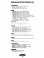
ABYC, NFPA AND USCG PUBLICATIONS FOR
INSTAlLING DIESEL ENGINES
Do not wear loose clothing or jewelry when servicing
equipment; tie back long hair and avoid wearing loose
jackets, shirts, sleeves, rings, necklaces or bracelets that
could be caught in moving parts.
Read the following ABYC, NFPA and USCG publications
for safety codes and standards. Follow their recommenda-
Make sure all attaching hardware is properly tightened.
Keep protective shields and guards in their respective
places at all times.
tions when installing your engine.
ABYC (American Boat and Yacht Council)
"Safety Standards for Small Craft"
Do not check fluid levels or the drive belt's tension while
!hi: engine is operating.
•
Order from:
ABYC
15 East 26th Street
New York, NY lOOlO
Stay clear of the drive shaft and the transmission coupling
when the engine is running; hair and clothing can easily
be caught in these rotating parts.
NFPA (National Fire Protection Association)
"Fire Protection Standard for Motor Craft"
HAZARDOUS NOISE
Order from:
A WARNING: High nl1lse lewis can cause hearing
National Fire Protection Association
II1tIsI
•
•
Never operate an engine without its muffler installed.
Do not run an engine with the air intake (silencer)
•
removed.
Do not run engines for long periods with their enclosures
II Tracy Drive
Avon Industrial Park
Avon, MA 02322
USCG (United States Coast Guard)
"USCG 33CFR183"
Order from:
open.
U.S. Government Printing Office
Washington, D.C. 20404
A WARNING: 011 nl1t Wl1t1c I1n machinery when Yl1u are
mentally I1r physically Incapacitated by fatigue!
OPERATORS MANUAl
Many of the preceding safety tips and warnings are repeated
in your Operators Manual along with other cautions and
notes to highlight critical information. Read your manual
carefully, maintain your equipment, and follow all safety
procedures.
ENGINE INSTAllATIONS
Preparations to install an engine should begin with a thorough examination of the American Boat and Yacht Council's
(ABYC) standards. These standards are a combination of
sources including the USCG and the NFPA.
Sections of the ABYC standards of particular interest are:
H-2 Ventilation
P-I Exhaust systems
P-4 Inboard engines
E-9 DC Electrical systems
All installations must comply with the Federal Code of
Regulations (FCR).
iii
INSTALLATION
When installing WESTERBEKE engines and generators it is important that strict
attention be paid to the following information:
CODES AND REGULATIONS
Strict federal regulations, ABYC guidelines, and safety codes must be complied with
when installing engines and generators in a marine environment.
SIPHON-BREAK
For installations where the exhaust manifold/water injected exhaust elbow is close to
or will be below the vessel's waterline, provisions must be made to install a siphonbreak in the raw water supply hose to the exhaust elbow. This hose must be looped a
minimum of 20" above the vessel's waterline. Failure to use a siphon-break when
the exhaust manifold byeclion port is at or below the load waterline will result in
raw water damage to the engine and possible flooding of the boat.
If you have any doubt about the position of the water-injected exhaust elbow relative
to the vessel's waterline under the vessel's various operating conditions, ins/all a
siphon-break.
NOTE: A siphon~break requires periodic inspection and cleaning to ensure proper
operation. Failure fa pmperly maintain a siphon-break can result in catastrophic
engine damage. Consult the siphon-break manufacturer for proper maintenance.
EXHAUST SYSTEM
The exhaust hose must be certified for marine use. The system must be designed to
prevent water from entering the exhaust under any sea conditions and at any angle
of the vessels hull.
A detailed Marine Installation Manual covering gasoline and diesel
engine and generators is suppied with each unit. Additional copies
can be obtained from our website in pdf form. www.westerbeke.com.
,/, .Univorsal
iv
AVAILABLE FROM
YOUR WESTERBEKE
DEALER
TABLE OF CONTENTS
Parts Identification ......................................................... .2
Introduction .......................................................................3
Wiring Schematic (Catalina) ......................................... 26
Engine Adjustments .......................................................27
Warranty Procedures .................................................... 3
Serial Number Location .............................................. .3
Throttle and Stop Assembly ....................................... 27
Valve Clearance .......................................................... 27
Testing Engine Compression ...................................... 28
Testing Oil Pressure ................................................... 28
Fuel Injectors ............................................................. .28
Admiral Control Panel .....................................................5
Captain Control Panel .....................................................6
DIesel Fuel, Engine Oil and Engine Coolant ............... 7
Preparations for Initial Start-Up ................................... 8
StartlngJStopplng Procedure ..........................................9
Break-In Procedure ........................................................ 10
The Dall, Routine ........................................................... 11
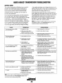
Engine Troubleshooting (Chart) ................................... 29
Control Panel Troubleshooting (Chart) ...................... .31
Troubleshooting Water Temperature .......................... 31
Troubleshooting Oil Pressure Gauges ........................ 31
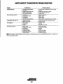
Tachometer Troubleshooting ........................................32
PRM Transmissions ........................................................34
Changing the Fluid ..................................................... 34
Gear Shifting ............................................................. .34
Daily Operation ......................................................... .35
Control Cables ............................................................ 35
Maintenance ............................................................... 35
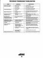
Transmission Troubleshooting (Chart) ........................ 36
HBW Transmission ..........................................................37
Shaft Couplings .......................................................... 37
Shift Lever .................................................................. 37
Fluid Change .............................................................. 38
Specifications ............................................................. 38
Operating Temperature ............................................... 39
Transmission Cooler ........ " ............ ,............................ 39
Maintenance .............................................................. .39
Transmission Troubleshooting (Chart) ....................... .40
Control Cables ........................................................... .40
Lay-Up and Recommissioning ......................................42
SpeCifications .................................................................44
Alarms and Circuit Breakers ..................................... .11
Maintenance Schedule .................................................. 12
EngIne Cooling Clrcuil... ................................................ 14
Raw Water Pump ........................................................ 15
Changing the Raw Water Impeller. ............................ IS
Raw Water Intake Strainer ......................................... 16
Therrnostat... ............................................................... 16
Heat Exchanger .......................................................... 16
EngIne 011 Change .......................................................... 17
Remote 011 Filter ............................................................ 18
Fuel s,stem ..................................................................... 19
Air Cleaner/Silencer ................................................... 19
Priming the Fuel System ............................................ 19
Fuel Lift Pump ........................................................... 19
Fuel Filters ................................................................. 20
DC ElectrIcal Srstem .....................................................2I
Drive Belt Adjustment ............................................... 21
Battery Care ............................................................... 21
Glow Plugs ................................................................21
Alternator Troubleshooting ........................................ 22
WIrIng DIagram ...............................................................23
WirIng Schematic ...........................................................24
WirIng DIagram (Catalina) .............................................25
Spare Parts ......................................................................45
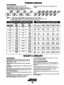
Standard Hardware Torques ........................................ .46
Metric Conversions ....................................................... .47
European Maritime Council Certificate .................... .49
1
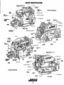
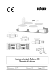
PARTS IDENTIFICATION
MANIFOLO'p'R.E.SSUI~E C,~P
FILL
ICOOLANT
THERMOSTAT
ASSEMBLY
M-40BILLUSTRATED
=::;>F\-\---j\lR FIlTER SILENCER
~~~~:d "\l!i-of-----OIL DRAIN HOSE
CAP
ALTERNATOR
REAR
RIGHT SIDE
COOLANT PUMP .u«"'r-~
OIL
PREHEAT
SOLENOID
OIL PAN
COOLANT
DRAIN
/ MA."ULU PRESSURE CAP
FILL]
1.0. NAME PLATE
FUEL
PUMP
REAR
FUEL
START
MOTOR
COOLANT PUMP-~--->j1U1i
SHEAVE
~m---.T,
RAW WATER PUHIP---'''>',L
M-50BILLUSTRATED
OIL
FRONT
OIL DRAIN HOSE
OIL
2
LEFT SIDE
INTRODUCTION
PRODUCT SOFTWARE
These new high performance UNIVERSAL marine diesel
engines are a product of UNIVERSAUWESTERBEKE' S
design technology and their combined years of experience
manufacturing quality marine engines. We take great pride in
the superior durability and dependable performance of our
marine engines. Thank you for selecting UNIVERSAL.
Product software (tech data, parts lists, manuais, brochures and
catalogs) provided from sources other than UNIVERSAL are not
within UNIVERSAL'S CONTROL.
UNIVERSAL CANNOT BE RESPONSIBLE FOR THE
CONTENT OF SUCH SOFTWARE, MAKES NO WARRANTIES OR REPRESENTATIONS WITH RESPECT
THERETO, INCLUDING ACCURACY, TIMELINESS OR
COMPLETENESS THEREOF AND WILL IN NO EVENT
BE LIABLE FOR ANY TYPE OF DAMAGE OR INJURY
INCURRED IN CONNECTION WITH OR ARISING OUT
OF THE FURNISHING OR USE OF SUCH SOFTWARE.
In order to get the full use and benefit from your engine, it is
important that you operate and maintain it correctly. This
manual is designed to help you do this. Please read this
manual carefully and observe all the safety precautions
throughout. An extensive network of UNIVERSAL
WESTERBEKE distributors, dealers and service centers are
available worldwide. Should your engine require servicing,
contact your nearest dealer for assistance.
UNIVERSAL customers should also keep in mind the time
span between printings of UNIVERSAL product software
and the unavoidable existence of earlier UNIVERSAL
manuals. In summation, product software provided with
UNIVERSAL products, whether from UNIVERSAL or other
suppliers, must not and cannot be relied upon exclusively as
the definitive authority on the respective product. It not only
makes good sense but is imperative that appropriate representatives of UNIVERSAL or the supplier in question be
consulted to detennine the accuracy and currentness of the
product software being consulted by the customer.
This is your operators manual. A Parts Catalog is also
provided and a Thchnical Manual is available from your
UNIVERSAL dealer. Also, if you are planning to install this
equipment, contact your UNIVERSAL dealer for
UNIVERSAL'S installation manual.
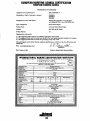
WARRANTY PROCEDURES
Your UNIVERSAL Warranty is included in a separate folder.
If you have not received a customer identification card registering your warranty 60 days after submitting the warranty
registration form, please contact the factory in writing with
model information, including the unit's serial number and
commission date.
NOTES, CAUTIONS AND WARNINGS
As this manual takes you through the operating procedures,
maintenance schedules, and troubleshooting of your marine
engine, critical information will be highlighted by NOTES,
CAUTIONS, and WARNINGS. An explanation follows:
Unlvarsal
NOTE: An operating procedure essential to note.
A
CAUTION: Procedures, which If not strictly
observed, can result In the damage or destruction of
your engine.
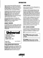
Customer Identification
UNIVERSAL OWNER
MAIN STREET
HOMETOWN, USA
Model M-35B
A
WARNING: Procedures, which if not properly
followed, can result In personal InJury or loss of life.
Ser. #D704XXXX
Expires 712012000
TYPICAL CUSTOMER IDENTIFICATION CARD
The UNIVERSAL serial number is an alphanumeric number
that can assist in determining the date of manufacture of your
UNIVERSAL engine. The first character indicates the decade
[A=1960s, B=1970s, C=1980s, 0=1990, etc.], the second
character represents the year in the decade, and the fourth
and fifth numbers represent the month of manufacture.
3
INTRODUCTION
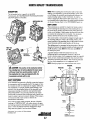
SERIAL NUMBER LOCATION
ORDERING PARTS
An identification nameplate that displays the engine model
number and engine serial number is mounted on the side of
the engine's manifold. Take the time to enter this information
on the blank decal provided below. This will provide a quick
reference when seeking technical information and/or ordering
Whenever replacement parts are needed, always provide the
engine model number and engine serial number as they
appear on the silver and black identification nameplate
located on the manifold. You must provide us with this information so we can identify your engine. In addition, include a
complete part description and part number for each part
needed (see the separately furnished Parts Catalog). Also
insist upon UNIVERSAUWESTERBEKE packaged parts
because will fit or generic parts are frequently not made to
the same specifications as original equipment.
parts.
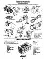
SPARES AND ACCESSORIES.
Certain spares will be needed to support and maintain
your UNIVERSAL marine engine. Your UNlVERSAU
WESTERBEKE dealer will assist you in preparing an on
board inventory of spare parts. See the UNIVERSAL SPARE
PARTS page in this manual for a suggested list.
IllJERSTANDING THE DIESEL ENGINE
The diesel engine closely resembles the gasoline engine,
since the mechanism is essentially the same. The cylinders
are arranged above a closed crankcase; the crankshaft is of
the same general type as that of a gasoline engine, and the
diesel engine has the same types of valves, camshaft, pistons,
connecting rods and lubricating system.
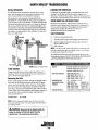
PROTECTING YOUR INVESTMENT
Care at the factory during assembly and thorough testing
have resulted in a UNIVERSAL diesel engine capable of
many thousands of hours of dependable service. However the
manufacturer cannot control how or where the engine is
installed in the vessel or the manner in which the unit is
operated and serviced in the field. This is up to the
buyer/owner-operator.
To a great extent, a diesel engine requires the same preventive maintenance as a gasoline engine. Most important are
proper ventilation and proper maintenance of the fuel, lubrieating and cooling systems. Replacement of fuel and lubricating filter elements at the time periods specified and
frequent checking for contamination (water, sediment, etc.) in
the fuel system are essential. Also important is the consistent
use of a brand of high detergent diesel lubrication oil
designed specifically for diesel engines.
NOTE: Six important steps to ensure long engine life:
o Proper engine installation and alignment.
o An efficient well-designed exhaust system that includes
an anti-siphon break to prevent water from entering the
engine.
The diesel engine does differ from the gasoline engine, however, in its method of handling and firing of fuel. The carburetor and ignition systems are done away with and in their
place is a single component (the fuel injection pump) which
performs the function of both.
o Changing the engine oil and oil filters every 100 operating
hours.
D Proper maintenance of all engine components according
to the maintenance schedule in this manual.
o Use clean, filtered diesel fuel.
o Winterize your engine according to the LAY-UP AND
RECOMMISSIONING section in this manual.
4
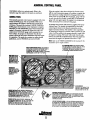
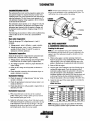
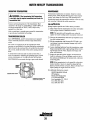
ADMIRAL CONTROL PANEL
UNIVERSAL offers two optional panels. Refer to the
instruction page that applies to the panel you purchased.
When the engine is shut down with the Key Switch turned
off, the water temperature gauge will continue to register the
last temperature reading indicated by the gauge before electrical power was turned off. The oil pressure gauge will fall
to zero when the Key Switch is turned off. The temperature
gauge will once again register the engine's true temperature
when electrical power is restored to the gauge.
ADMIRAL PANn
This manually-operated control panel is equipped with a Key
Switch and RPM gauge with an ELAPSED TIME meter
which measures the engine's running time in hours and in
1110 hoUIS. The panel also includes a WJ'JER TEMPERA·
TURE gauge which indicates water temperature in degrees
Fahrenheit, an OIL PRESSURE gauge which measures the
engine's oil pressure in pounds per square inch, and a DC
control circuit VOLTAGE gauge which measures the system's voltage. All gauges are illuminated when the key
switch is turned on and remain illuminated while the engine
is in operation. The panel also contains two rubber-hooted
pushbuttons, one for PREHEPJ and one for START.
A separate alarm buzzer with harness is supplied with every
Admiral Panel. The installer is responsible for electrically
connecting the buzzer to the four-pin connection on the
engine's electrical harness. The installer is also responsible
for installing the buzzer in a location where it will be dry and
where it will be audible to the operator should it sound while
the engine is running. The buzzer will sound when the ignition key is turned on and should silence when the engine has
started and the en~ine's oil pressure rises above 15 psi.
Nole: Refer to the WIRING DIAGRAM in this manual for the
installation of two engine sendors.
WATER TEMPERATURE GAUGE: TliIS GAUGE IS
GRADUATED IN DEGREES FAHRENHEIT AND IS
IllUMINATED WHILE TliE KEY SWITCH IS
TURNED ON. TliE ENGINE'S NORMAl OPERATING
TEMPERATURE IS 170'-190' F (77'-aa'C).
OIL PRESSURE GAUGE: THIS GAUGE IS GRADUATED IN POUNDS PER SQUARE INGH (PSI) AND IS
ILLUMINATEO WHILE THE KEY SWITCH IS
TURNED ON. THE ENGINE'S NORMAL OPERATING
OIL PRESSURE RANGES BETWEEN 30·60 PSI.
RECAUBRATEO FOR
ACCURACY FROM THE
REAR OF THE PANEl.
KEY SWtTCH: PROVIDES
CLUSTER.
INDICATES THE AMOUNT THE
BATTERY IS BEING CHARGED.
SHOULD SHOW 13VTO 14V.
HAS BEEN
FRESH
WATER
2tO' F(9S'C), THIS SWITCH WILL CLOSE
SOUNDING THE ALARM WHICH WILL EMIT A
CONTINUOUS SIGNAl.
~~l!~INji~~!~CJIF.:~~~E~
I
THIS BUTTON
PRBtfAT BUTTON: WHEN PRESSED. ENERGIZES
AlTERNATOR'S REGULATOR, THE FUEL LIFT PUMP AND
THE ENGINE'S GLOW PLUGS, AND BYPASSES THE'
ENGINI"S OIL PRESSURE ALARM SWITCH. IN ADDITlDN,1HIS BUTTON ENERGIZES THE START BUTTON.
LOW OIL'PRESSURE ALARM: A LOW OIL PRESSURE ALARM SWITCH
IS LOCATED OFF THE ENGINE'S OIL GALLERY. THIS SWITCH MONITORS
THE ENGINE'S OIL PRESSURE. SHOULD THE ENGINE:S OIL PRESSURE
FALL TO 5 -10 PSI, THE SWITCH WILL OPEN SOUNDING THE ALARM.
IN THIS EVENT, THE ALARM WILL EMIT A PULSATING SIGNAL.
5
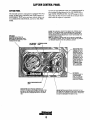
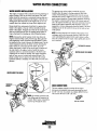
CAPTAIN CONTROL PANEL
and one for high ENGINE COOLANT TEMPERATURE. It
also includes an alarm buzzer for low on.. PRESSURE or
high WA1ER TEMPERATURE. The RPM gauge is illuminated when the Key Switch is turned on and remains illumi-
CAPTAIN PANEL
This manually-operated control panel is equipped with a Key
Switch, an RPM gauge, PREHEAT and START buttons, an
INSTRUMENT TEST button and three indicator lamps, one
for AL1ERNATOR DISCHARGE, one for low On.. PRESSURE,
nated while the engine is in operation.
ALARM: THE ALARM WILL SOUND IF THE ENGINE'S OIL PRESSURE FALLS
BELOW 5 -10 PSI. IN THIS EVENT, THE ALARM WILL EMIT A PULSATING
SIGNAl. THE ALARM WILL ALSO SOUND IF THE WATER TEMPERATURE IN
THE FRESHWATER COOLING CIRCUIT RISES TO 210°F IN THIS EVENT, THE
ALARM WILL EMIT A SIGNAl.
NOTE: THE ALARM WILL SOUND WHEN THE KEY SWITCH IS TURNED ON.
THIS SOUNDING IS NORMAl. ONCE THE ENGINE STARTS AND THE ENGINE'S
OIL PRESSURE REACHES 15 PSI, THE ALARM WILL SILENCE.
RPM GAUGE:
REGISTERS REVOLUTIONS PER
MINUTE OF THE ENGINE AND CAN BE
RECALIBRATED FOR ACCURACY FROM
THE REAR OF THE PANEl.
TEST BUTTON: WHEN
PRESSED, TESTS THE
ALTERNATOR, THE OIL
PRESSURE, AND THE
WATER TEMPERATURE
CONTROL CIRCUITS.
WHEN PRESSED, THE
ALTERNATOR, THE OIL
PRESSURE, AND THE
WATER TEMPERATURE
INDICATOR LIGHTS
ILLUMINATE IN ADDITION TO SOUNDING
THE ALARM BUZZER.
KEY SWITCH:
PROVIDES POWER TO
THE INSTRUMENT
PANEL CLUSTER AND
THE DC ALTERNATOR
REGULATOR TERMINAL.
WATER TEMPERATURE ALARM
LIGHT
START BUTTON: WHEN PRESSED, ENERGIZES THE
STARTER'S SOLENOID WHICH CRANKS THE ENGINE. THIS
BUTTON WILL NOT OPERATE ELECTRICALLY UNLESS THE
PREHEAT BUTTON IS PRESSED AND HELD AT THE SAME
TIME.
6
PREHEAT BUTTON: WHEN PRESSED, ENERGIZES THE FUEL
LIFT PUMP AND THE ENGINE'S GLOW PLUGS, AND BYPASSES
THE ENGINE'S OIL PRESSURE ALARM SWITCH. IN ADDITION,
THIS BUTTON ENERGIZES THE START BUTTON.
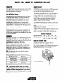
DIESEL FUEL, ENGINE OIL AND ENGINE COOLANT
DIESEL FUEL
ENGINE COOLANT
Use a diesel fuel that meets the requirements of No.2-D SAE
J 313 and has a Cetane rating of #45 or higher. Grade of
diesel fuel according to ASTM 0975.
UNIVERSAL recommends a mixture of 50% antifreeze and
50% distilled water. Distilled water is free from the
chemicals that can corrode internal engine surfaces.
The antifreeze performs double duty. It allows the engine to
run at proper temperatures by transferring heat away from
the engine to the coolant, and lubricates and protects the
cooling circuit from rust and corrosion. Look for a good
quality antifreeze that contains Supplemental Cooling
Additives (SCAs) that keep the antifreeze chemically
Care Of The Fuel Supply
Use only clean diesel fuel! The clearance of the components
in your fuel injection pump is very critical; invisible dirt
particles which might pass through the filter can damage
these finely finished parts. It is important to buy clean f
fuel, and keep it clean. The best fuel can be rendered
unsatisfactory by careless handling or improper storage
facilities. To assure that the fuel going into the tank for your
engine's daily use is clean and pure, the following practice is
advisable:
balanced, crucial to long tenn protection.
The distilled water and antifreeze should be premixed before
being poured into the cooling circuit.
NOTE: Laokfor the new environmentally-friendly long lasting
antifreeze that is now available.
Purchase a well-known brand of fuel.
Antifreeze mixtures will protect against an unexpected freeze
and they are beneficial to the engine's cooling system. They
retard rust and add to the life of the circulating pump seal.
Install and regularly service a good, visual-type filter/water
separator between the fuel tank and the engine. Raycor 230
or 245 are good examples of such a filter. Micron filter rating
of # IO is recommended.
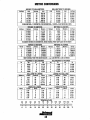
ANTIFREEZE PROTECTION
Antifreeze concentralion
Freezing Temperature
ENGINE OIL
Use a heavy duty engine oil with an API classification of CF,
CG-4, CH-4 or CI-4. Change the engine oil and filter after
the initial 50 hours of break-in operation., Then follow the oil
and filter change intervals as specified in the
MAINTENANCE SCHEDULE in this manual.
Westerbeke Corporation does not approve or disapprove
the use of synthetic oils. If synthetic oils are used, engine
break-in must be performed using conventional oil. Oil
change intervals must be as listed in the MAINTENANCE
SCHEDULE section in this manual and not be extended if
synthetic oils are used.
23%
14°F
WC)
For recommended oil viscosity, see the following chart:
Above 6soF (20°C)
SAE 30 0.1 OW-30
41°-6soF (5-20°C)
SAE 20 or 10W-30
Below 41°F (5°C)
SAE 10W-30
50%
-40°F
(-40"C)
A coolant recovery tank kit is supplied with each
UNIVERSAL diesel engine. The purpose of this recovery
tank is to allow for engine coolant expansion and contraction
during engine operation, without the loss of coolant and
without introducing air into the cooling system.
regarding synthetic oil.
011 Viscosity
35%
-4°F
(-20°C)
COOLANT RECOVERY TANK
NOTE: The in/ormation above supersedes all statements
Opendlng Temperatu.e
30%
COOLANT RECOVERY TANK
A
CAUTION: Do not allow two or more brands of
II1I/Ilne 011 to mix. Each brand contains its own additives;
additives of different brands could react in the mixture
til prtJdllce prtJperties harmful to your engine.
7
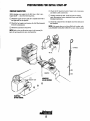
PREPARATIONS FOR INITIAL START-UP
PRESTART INSPECTION
o Check the DC electrical system. Inspect wire connections
Before starting your engine for the first time or after a prolonged layoff - check the following items.
o Visually examine the unit. Look for loose or missing
and battery cable connections.
parts, disconnected wires, unattached hoses, and check
threaded connections.
o Check the engine oil level; add oil to maintain the level at
the high mark on the dipstick.
o Check the coolant level in the plastic recovery tank and at
o Check the fuel supply and examine the fuel filter/separator
the manifold.
bowls for contaminants.
NOTE: If the engine has not yet been filled with coo/ant, refer
to the ENGINE COOLING CIRCUIT section of this manual.
o Check the transntission fluid level.
NOTE: Refer to the specifications pages in this manual for
fuel, oil, and transmission types and quantities.
COOLANT
RECOVERY
TANK
MANtFOLD
MANIFOLD
IM-35B SHOWN)
(&J
8
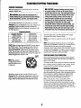
STARTING/STOPPING PROCEDURE
STARTING PROCEDURE
A CAUTION: Prolonged cranking intervals without
Place the transmission in neutral and advance the throttle
control to slightly open.
the engine starting can result in the engine exhaust
system filling with raw water. This may happen because
the pump is pumping raw water through the raw water
COOling system during cranking. This raw water can
enter the engine's cylinders by way of the exhaust
manifold once the exhaust system fills. Prevent this
from happening by closing the raw water supply
through·hull shutoff, draining the exhaust muffler, and
conecting the cause of the excessive engine cranking,
Engine damage resulting from raw water entry is not a
warrantable issue; the owner/operator should keep this
A
CAUTION: Make certain the transmission is in
1IIIIIIrBI. StartIng In gear could resun in serious damage
'" JOIIf transmission, your boat, and vessels nearby.
Thrn the KEY SWITCH to the ON position (2 o'clock).
PREHEAT:Depress the PREHEAT switch. The voltmeter and
panel lights, gauges and meters will be activated. The
PREHEAT switch should be depressed in accordance with
the following chart:
TemperatureJPreheat
... "'.... Ie Tompondun
41"f(S'C) or higher
41 "f(S'C) to 23'F (-5'C)
23'F(-5'C) or lower
UmH of conll.uou. use
Preheallng TIme
Approx. 10 seconds
Once the engine starts, check the instruments for proper
oil pressure and battery charging voltage.
Approx. 15 seconds
Approx. 20 seconds
30 seconds before cranking
NOTE: Never attempt to engage the starter while the engine is
running.
NOTE: Some unstable running may occur in a cold engine.
Depressing the PREHEAT switch for 10·15 second intervals
will help stabilize the engine rpm until the operating
temperature of the engine reaches 150·170 F. (60-77 C) and
a propeller load is applied 10 the engine. When the engine is
running and the PREHEAT switch is depressed, a charging
load on the DC alternator will be discernible.
START:While still depressing the PREHEAT switch, depress
the STAKr button. This will engage the starter solenoid.
Upon engine starting, release the START switch. Do not
release the PREHEAT switch until the oil pressure reaches
15 psi. Then as long as the high water temperature and low
oil pressure protective circuits do not activate, the engine will
remain energized and continue to run.
STARTING UNDER COLD CONDITIONS
VOLTAGE
DROP
Make certain the lubricating oil conforms with the ratings for
the prevailing temperature. Check the table on the engine oil
section of this manual.
The battery should be fully charged to minimize voltage drop.
Use a sufficient amount of preheat to aid in starting. See the
Temperature/Preheat chart elsewhere in this section.
lUTE: When starting:
A voltage drop will occur
when the preheat button
is depressed.
STOPPING PROCEDURE
To stop the engine, bring the throttle to an idle position and
place the transmission in neutral. Allow the engine to idle for
a few moments to stabilize temperatures. Pull the STOP
lever to shut down the engine. Then tum OFF the key to
close down the electric fuel pump and accessories.
Make certain this key switch is in the OFF position
(12 o'clock).1fthe key switch is left ON, the battery will
discharge. An engine alarm buzzer is provided to warn the
operator of this condition (Key Switch ON). The best method
of preventing the battery from discharging is to remove the
key from the Key Switch after stopping the engine. (The extra
key should be stowed in a safe place.)
Should the engine not start when the START switch is
depressed for 10 to 20 seconds, release both switches and
wail 30 seconds; repeat the procedure above and preheat
longer. Never run the starler for more than 30 seconds.
9
BREAK-IN PROCEDURE
THE FIRST 50 HOURS
Breaking-in a new engine basically involves seating the
piston rings to the cylinder walls. This cannot be accomplished
by long periods of running at idle, nor by early running at full
rpm. Idle running may glaze the cylinder walls, resulting in
Although your engine has experienced a minimum of one
hour of test operations to ensure accurate assembly and
proper operation of all systems, break-in time is required.
The service life of your engine is dependent upon how the
engine is operated and serviced during its initial 50 hours of
excessive oil consumption and smoky operation. Excessive
use,
Your new engine requires approximately 50 hours of initial
conditioning operation to break in each moving part in order
to maximize the performance and service life of the engine.
Perform this conditioning carefully, keeping in mind the
following:
1. Start the engine according to the Starting Procedure
section in this manual; run the engine at fast idle while
checking that all systems (raw water pump, oil pressure,
battery charging) are functioning.
2. Allow the engine to warm up (preferably by running at fast
idle) until the water temperature gauge moves into the
130°-1400P range.
3. While using the vessel, run the engine at varying engine
rpms for the first 25 hours.
speed or heavy over-loading, especially with a cold engine,
may cause scoring of the cylinder walls, producing similar
results. Operate the engine in moderation during the 50-hour
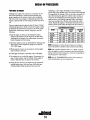
break-in period. (Don't baby the engine, but do not abuse it.)
MODEL
M3-20B
M25XPB
M35B
M40B
M50B
RECOMMENDED RPM RANGES
CRUISE
IDLE
RPM
RPM
1000 -1200
2500 - 3000
1000 -1200
2000 - 2500
800 - 1000
2000 - 2500
800 - 1000
2000 - 2500
800 -1000
2000 - 2500
MAXIMUM
RPM
3500 - 3600
2900 - 3000
2900 - 3000
2900 - 3000
2700 - 2800
NOTE: Attempting to reduce idle speed below the minimum
shown may produce unstable engine operation and stalling.
NOTE: The propeller should be either 2 or 3 blade. It should
allow the engine to reach its maximum rated rpm at full open
throttle underway in forward gear to ensure the availability of
rated horsepower when needed.
4. Avoid rapid acceleration, especially with a cold engine.
S. Use caution not to overload the engine. The presence of a
NOTE: See the 1RANSMISSION section of this manual for
break-in information on your transmission.
gray or black exhaust, and the inability of the engine to
reach its full rated rpm, are signs of an overload.
6. During the next 25 hours, the engine may be operated at
varying engine rpms, with short runs at full rated rpm.
Avoid prolonged idling during this break-in period.
10
THE DAILY ROUTINE
CHECK LIST
START YOUR ENGINE
Each day before starting your engine, take a few moments to
run this check list:
NOTE: See STARTING STOPPING PROCEDURE in this
manual for more detailed instructions.
o Visually inspect the engine for fuel, oil, coolant and
I. Put transmission in neutral, throttle advanced.
exhaust leaks.
2. Turn KEY to the ON position (2 O'clock)
o Check the oil level.
o Check the transmission fluid level.
o Check for loose wires at the alternator.
3. Depress PREHEAT (10 to 15 seconds).
4. While pressing PREHEAT, push the START.
As engine fires - release START and PREHEAT.
o Check for loose wires and electrical connections at the
5. Observe the panel gauges, check the oil pressure, DC
charges, etc. Check for water discharge with the exhaust.
DC altemator and elsewhere on the engine's DC harness.
o Check the staJiing batteries level (weekly)
NOTE: Should engine fail fa start, wait 30 secollds, repeat tlte
above procedure, alld PREHEAT longe!:
o Check drive belts for wear and proper tension (weekly).
6. Allow a few minutes for the engine to warm at a
comfortable high idle (1400 - 1500 rpm), then reduce the
rpm to the normal idle position, shift into gear, anci get
underway.
o Log your engine running time. These hours relate to
scheduled_maintenance.
o Check fuel supply; always keep fuel tank(s) as full as
possible.
A
o Look for clean fuel in the fueVwater separator bowl.
.0
CAUTION: When shifting the transmission,
always reduce the engine rpm to idle, then shift the
transmission firmly from one direction to another. A
slight pause in neutral will allow the propeller to slow.
Shifting at high rpm will damage the
transmission/damper plate,
Check the coolant level in the plastic recovery tank.
o Check for any obviously loose components or nuts or
bolts.
NOTE: Excessive loss of coolant indicates a cooling system
leak. Check the entire system. If necessary, use a cooling system presslire lester to pressurize the cooling system to locate
the area of leakage. In cases of excessive coolant loss, refill
tlte system as outlined in tlte ENGINE COOLING CIRCUIT
section il1 this manual.
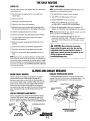
ALARMS AND CIRCUIT BREAKER
ENGINE CIRCUIT BREAKER
COOLANT TEMPERATURE SWITCH
The DC hamess on the engine is protected by an enginemounted manual reset circuit breaker (20 amps DC).
Excessive CUiTent draw or electrical overload anywhere in
A coolant temperature switch is located on the thermostat
hOllsing. This switch will activate a continuous alarm if the
coolant's operating temperature reaches approximately
the instrument panel wiring or engine wiring will cause the
21O'F (99'C).
breaker to trip. In this event most engines will shut down
because the open breaker disconnects the fuel supply. If
this should occur, check and repair the source of the problem.
After repairing the fault, reset the breaker and restrui the
engine.
AIR BLEED PETCOCK
COOLANT rEMI'ERI,TURE,
SEND OR
LOW OIL PRESSURE ALARM SWITCH
Allow oil pressure alarm switch is located off the engine's
oil gallery. This switch's sensor monitors the engine's oil
pressure. Should the engine's oil pressure fan to 5 -to psi
(0.4 - 0.7 kg/cm'), this switch will activate a pulsating alarm.
PRESSURE ALARM SWITCH
THERMOSTAT ASSEMBLY
IM-50B SHOWN]
OIL GALLERY
IM-50B SHOWN]
11
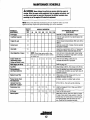
MAINTENANCE SCHEDULE
A
WARNING: Never attempt to pertonn any service whIle the engine is
runnIng. Wear the proper safety equIpment such as goggles and gloves, and
use the correct tools tor each Job. DIsconnect the battery tennlnals when
servIcIng any of the engIne's DC electrical equIpment.
NOTE: Many of the following maintenance jobs are simple but others are more
difficult and may require the expert knowledge of a service mechanic.
SCHEDULED
MAINTENANCE
CHECK
EACH
DAY
HOURS OF OPERATION
50
100
250
500
750 1000 1250
EXPLANATION OF SCHEDULED
MAINTENANCE
Diesel No.2 rating of 45 cetane or higher.
Fuel/Waler Separator
0
0
Engine 011 Level
0
Oil level should indicate between MAX. and LOW on
dipstick.
Coolant Level
0
Check at recovel)' tank; if empty, check at manifold.
Add coolant if needed.
Drive Belts
0
Inspect for proper tension (3/8" to 1/2" depression)
and adjust if needed. Check belt edges for wear.
Vlsuallnspectlon of Engine
0
Fuel Supply
Engine Throttle and
Transmission Control
Cables and Shutoff Levers
Adjust engine Idle Speed
Check for water and dirt in fuel (drain/replace filter
if necessal)').
NOTE: Please keep engine suiface clean.
DirI and oil will inhibit the engine's ability
to remain cool.
0
0
0
0
0
0
0
Starting Batteries
(and House Batteries)
0
engine 011 and Filter
0
0
0
0
0
0
0
0
0
0
0
0
0
Initial engine oil & filter change at 50 hrs., then
change both evel)' 100 hours.
At engine overhaul or cylinder head overhaul.
Lubricate Panel Key
Switch wllh "Lockeze"
At first 100 hrs., then each year at winterizing.
0
0
Air Cleaner
Exhaust System
Initial change at 50 hrs, then change every 250 hrs.
EveI)' 50 operating hours check electrolyte levels
and make sure connections are vel)' tight. Clean off
excessive corrosion.
'Torque Cylinder Head
Hold Down Bolts
Transmission Fluid
Check for loose fittings, cotter pins, etc.
Lubricate with WD-40 or equivalent.
Refer to page 10.
0
Fuel Filter
Check for fuel, oil and water leaks. Inspect wiring
and electrical connections. Keep bolts & nuts tight.
Check for loose belt tension.
0
0
0
0
0
0
0
0
12
0
0
Initial fluid change at 50 hrs., then every 250 hrs.
or once a year.
0
0
Clean the filter and element.
Initial check at 50 hrs .. then evel)' 500 hrs. Inspect
for leaks. Check siphon break operation. Check the
exhaust elbow for carbon and/or corrosion buildup
on inside passages; clean and replace as necessal)'. Check that all connections are tight.
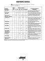
MAINTENANCE SCHEDULE
NOTE: Use the engine hour meter gauge to log your engine hours or record your
engine hours by running time.
SCHEDULED
MAINTENANCE
CHECK
EACH
DAY
HOURS OF OPERATION
EXPLANATION OF SCHEDULED
MAINTENANCE
50
100
250
500
750 1000 1250
Engine Hoses
0
0
0
0
0
0
0
Hose should be hard & tight Replace if soft or
spongy. Check & tighten all hose clamps.
Heat Exchanger
Zinc Anode
0
0
0
0
0
0
0
Clean or replace anode. Open heat exchanger end
cap and clean out debris. Remove every 1000 hours
for professional cleaning and pressure testing.
Electric Fuel Lift
Pump Filter (if applicable)
0
0
0
0
0
0
Clean at 50 hours, then clean every 250 hours.
0
Remove pump cover and inspect impeller for wear;
replace if needed. Also replace gasket Lubricate
both when reassembled. Inspect pump for internal
wear, cover plate wear and cam wear.
0
Drain, flush, and refill cooling system with
appropriate antifreeze mix.
Raw Water Pump
0
0
0
Coolant System
0
'Fuel Injectors
Check and adjust injection opening pressure and
spray condition (see Engine Adjustments).
'Starter Motor
0
0
Check solenoid and motor for corrosion. Remove
and lubricate. Clean and lubricate the starter motor
pinion drive.
'Preheat Circuit
0
0
Check operation of preheat solenoid. Remove and
clean glow plugs; check resistance (0.7-0.8 ohms).
'Engine Cylinder
Compression and
Valve Clearance
0
0
Incorrect valve clearance will result in poor engine
performance; check compression pressure and timing,
and adjust valve clearances.
0
Check DC charge from alternator. Check mounting
bracket; tighten electrical connections.
DC Alternator
0
0
Heat Exchanger
0
Remove, have professionally cleaned and pressure
tested.
'Engine Transmission
Damper Plate
0
Chattering at idle and low rpms is an indication of
damper plate wear. Remove and replace.
'UNIVERSAL recommends this service be performed by an authorized mechanic.
13
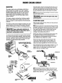
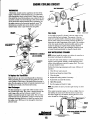
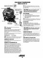
ENGINE COOLING CIRCUIT
Drain the engine coolant by loosening the drain plug on the
engine block and opening the manifold pressure cap. Flush
the system with fresh water, then start the refill process. See
the Parts Identification photos in this manual for locations.
DESCRIPTION
The engine is fresh water cooled (engine coolant) by an
engine-mounted heat exchanger. Raw water is pumped
through the heat exchanger by a gear-driven, positive displacement impeller pump. After the raw water cools the
engine coolant in the heat exchanger, it mixes with the
engine's exhaust gases, cools the exhaust gases, and discharges overboard.
. NOTE: The petcock on the heat exchanger can also be used to
help drain engine coolant.
AWARNING: Beware of the hot engine coolant. Wear
protectiVII gloves.
The engine's coolant is circulated by a belt-driven centrifugal-type metal impeller pump mounted on the front of the
engine. The engine's coolant temperature is thermostatically
controlled.
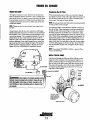
To Refill With Coolant
The engine's coolant must be changed according to the maintenance schedulO'in this manual. If the coolant is allowed to
become contaminated, it can lead to overheating problems.
ACAUTlON: Propllr cooling systBm mainfBnanclI is
critical; a substantia/numbllr of IInglnll failures can bll
traced back to cooling systllm corrosion.
A coolant recovery tank allows for engine coolant expansion
and contraction during engine operation, without any significant loss of coolant and without introducing air into the cooling system. This tank is best located at or above the engine
. should be easily accessible.
manifold
MHOB. M·!lJB COOLANT DRAIN JUST
ABOVE TH~E MOUNT
With the engine running in idle, slowly pour clean premixed
coolant into the manifold.
NOTE: Open the petcocks on the thermostat housing and heat
exchanger to help remove air from the system. When a steady
flow of coolant appears at the drain plug opening, close the
water drain plug and continue to fill the system until the
manifold remains full. Close'lhe petcock on the heat
exchanger when antifreeze flows from it.
.
Monitor the coolant in the manifold and add as needed. Fill
the manifold to the filler neck and install the pressure
cap.The petcock on the thermostat should also be opened
when refilling to allow trapped air to escape.
Remove the cap on the coolant recovery tank, fill with
coolant mix to halfway between LOW and MAX, and
replace the cap. Run the engine, close all petcocks and
observe the coolant expansion flow into the recovery tank.
After checking for leaks, stop the engine and allow it to cool.
Coolant shoui:! draw back into the cooling system as the
engine cools do·vn. Add coolant to the recovery tank if
needed. Clean up 'ny spilled coolant.
CAP
PRESSURE CAP
COOLANT
RECOVERY
TANK
MANIFOLD
M·40B
M·25XPB
M·35B
COOLAln
DRAIN
PRESSURE CAP
HEAT EXCHANGER
NOTE: Periodically check the condition of the pressure cap.
Ensure that the upper and lower rubber seals are in good
condition and check that the vacuum· valve opens and closes
tightly. Carry a spare cap.
M·50B COOLANT
DRAtN
ENGINE COOLING CIRCUIT
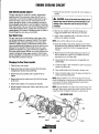
RAW WATER CODLING CIRCUIT
7. Check the cam and inner wear plate for wear. Replace as
needed.
The raw water flow is created by a positive displacement
impeller pump. This pump draws water directly from the
ocean, lake, or river from a through-hull opening through a
hose to the water strainer. The raw water passes from the
strainer through the pump to a heat exchanger (through the
heat exchanger tubes) where it cools the engine's circulating
fresh water coolant. The raw water is then discharged into the
water injected exhaust elbow, mixing with, and cooling the
exhaust gasses. This mixture of exhaust gas and raw water is
driven through the stem tube and overboard.
A
CAUTION: If any of the vanes have broken off the
impeller they must be found to prevent blockage in the
cooling circuit. They often can be found in the heat
exchanger.
8. Slide the new impeller onto the shaft taking care to
engage the impellers slot with the key on the shaft.
Raw Water Pump
9. Apply a film of petroleum jelly or silicone to the inner
surface of the impeller housing.
The raw water pump is a self-priming, rotary pump with a
non-ferrous housing and a neoprene impeller. The impeller
has flexible vanes which wipe against a curved cam plate
within the impell~r housing, producing the pumping action.
On no account should this pump be run dry as water acts as a
lubricant for the impeller. There should always be a spare
impeller and impeller cover gasket aboard (an impeller kit).
Raw water pump impeller failures occur when lubricant (raw
water) is not present during engine operation. Such failures
are. not warrantable, and operators are cautioned to make sure
raw water flow is present at start-up.
NOTE: Just coat the swiaee, do Ilot over apply.
10. Install the sealing O-ring in the impeller cover. Position
the gasket and wear plate and install the impeller housing
and secure in position with the 3 retaining bolts and
washers.
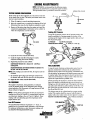
II. Mount the pump to the engine taking care that the end
seal and gasket are in place. Do not tighten the pump
mounting screws, just finger tight.
12. Reassemble the hose connections and open the raw
water intake,
Changing the Raw Water Impeller
I. Close the raw water intake.
13. Crank the engine a few revolutions to allow the pump to
center on its drive slot.
2. Remove the inlet and outlet port hoses from the pump,
noting the port location and positioning.
14. Stop cranking and secure the pump to the gear case.
3. Remove the pump assembly and its gasket from the
15. Start and run the engine, check for leaks and check for a
normal operating temperature.
engine.
NOTE: Should afai/ure occur with the pumps illtemal parts
(seals and bearings) if may be more cost efficient to purchase
a new pump. The price of individual pans would almost
match the price of a new pump.
4. Remove the three hex head screws that hold the housing
to the cover.
5. Remove the impeller cover exposing the impeller.
NOTE: Keep the slotted weep holes ill the pump hOllSillg clear
and open. Water found coming from these openings indicates
a shaft seal leak alld IIlllst be aI/ended to withow delay.
6. Pull the impeller off the shaft. Observe that the key on the
.
shaft is not lost.
RAW WATER PUMP
HOUSING
O-RING
15
COVER
ENGINE COOLING CIRCUIT
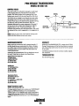
HEAT EXCHANGER
THERMOSTAT
A \hennostat, located near the manifold at the front of the
engine, controls the coolant temperature as it continuously
flows through the closed cooling circuit. When the engine is
flTSt started the closed thennostat prevents coolant from flowing (some coolant is by-passed through a hole in the thennostat to prevent the exhaust manifold from overheating). As
\he engine warms up the thennostat gradually opens. The
thennostat is accessible and can be checked. cleaned. or
replaced easily. Carry a spare thennostat and gasket.
ZINC ANODE
Zinc Anode
REPLACE
CLEAN & REUSE
A zinc anode (or pencil) is located in the raw water cooling
circuit within the heat exchanger. The purpose of the zinc
anode is to sacrifice itself to electrolysis action taking place in
the raw water cooling circuit, thereby reducing the effects of
electrolysis on other components of the syslem. The condition
of the zinc anode should be checked monthly and the anode
cleaned or replaced. as required. Spare anodes should be
carried onboard. The area in the exchanger where the anode
is located should periodically be cleaned of anode debris.
WATER
TEMPERATURE
SENDDR
RAW WATER INTAKE STRAINER
THERMOSTAT ASSEMBLY
(M-35B SHOWN)
NOTE: Always install the strainer at or below the waterline so
the strainer will always be self-priming.
A clean raw water intake strainer is a vital component of the
engine's cooling system. Include a visual inspection of this
strainer when making your periodic engine check. The water
in the glass should be clear.
THERMOSTAT
HOUSING
Perfonn the following maintenance after every 100 hours of
operation:
1. Close the raw water seacock.
2. Remove and clean the strainer filter.
3.
4.
5.
6.
To Replace the Thermostat
Remove the two cap screws and disassemble as illustrated.
When assembling the new thennostat and gasket put a thin
coat of sealant on both sides of the gasket before pressing in
place. Run the engine and check for nonnal temperatures and
.
that there are no leaks at the thennostat housing.
Clean the glass.
Replace the sealing washer if necessary.
Reassemble and install the strainer.
Open the soacock.
7. Run the engine and check for leaks.
NOTE: Also follow the above procedure after having run hard
aground.
Heat Exchanger
The beat exchanger is a copper tube which encloses a number of small copper tubes. Raw water is pumped through the
small copper tubes and the freshwater coolant from the
engine is circulated around the copper tubes. The raw water
removes heat from the freshwater coolant. To keep the heat
exchanger operating efficiently. it should be removed from
the engine every 1000 hours to be thoroughly cleaned and
pressure tested.
If the engine temperature gauge ever shows a higher than normal reading, the cause may be that silt, leaves or grass may
have been caught up in the strainer, slowing the flow of raw
water through the cooling system
'SEALING
WASHER
SEACOCK
:If':-t----
o!!£::::::l:2:f::!.
STRAINER
FILTER
RAW WATER INTAKE STRAINER
[TYPICAL)
16
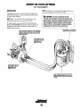
ENGINE OIL CHANGE
DRAIN THE SUMP
Replacing the Oil Filter
The engine oil should be warm. Remove the oil drain hose
from its attachment bracket and lower it into a container and
allow the oil to drain, or attach a pump to the end of the drain
hose and pump out the old oil. Make sure the oil drain hose
is capped and properly secured in its holder after all the old
oil has been drained.
When removing the used oil filter, you may find it helpful
and cleaner to punch a hole in the upper and lower portion of
the old filter to drain the oil from it into a container before
removing it. This helps to lessen spillage.
NOTE: Do not punch this hole without first loosening the filter
to make certain it will come off!
NOTE: Thread size for the lube oil drain hose capped end is
An automotive filter wrench should be helpful in removing
the old oil filter. Place some paper towels and a plastic bag
around the filter when unscrewing it to catch any oil left in
the filter. Inspect the old oil filter as it is removed to make
sure that the rubber sealing gasket comes off with the old oil
filter. If this rubber sealing gasket remains sealed against the
engine block, gently remove it. When installing the new oil
filter element, wipe the filter gasket's sealing surface on the
engine block free of oil and apply a thin coat of clean engine
oil to the rubber gasket on the new oil filter. screw the filter
onto the threaded oil filter stub, and tighten the filter firmly
by hand.
J/4NPT.
Always observe the old oil as it is removed. A yellow/gray
emulsion indicates the presence of water in the oil. Although
this condition is rare, it does require prompt attention to prevent serious damage. Call a competent mechanic if water is
present in the oil. Raw water present in the oil can be the
result of a fault in the exhaust system attached to the engine
and/or a siphoning of raw water through the raw water cooling circuit into the exhaust, filling the engine. This problem
is often caused by the poor location or the lack of an anti'
siphon valve, See UNIVERSAL'S Installation Manual.
NOTE: Use genuine UNIVERSAL oil filters - generic filters
are not recommended.
REFILL THE OIL SUMP
Add fresh oil through the filler cap. After refilling, run the
engine for a few moments while checking the engine's oil
pressure. Make sure there is no leakage around the new oil
filter or from the oil drain system, and then stop the engine.
Then check the quantity of oil with the lube oil dipstick. If
DRAIN HOSE
the engine requires additional oil, fill to, but not over, the
high mark on the dipstick.
--Smm !11n61 SOCKET
M·25XPB
M·35B
AWARNING: Used BnglnB 011 contains haflllful contaminants. Avoid prolongBd skin contact. Clean skin and
nails thofllugh/y using soap and water. LaundBf Of discard clothing Of rags containing uS/ld 011. Discard uS/ld
011 Pfllporly.
M·40B
1/4" NPT
...J.l.,~nl:-( BLOCK
DRAIN
OIL FILTER
SPIN·ON Oil FIlTER
17
REMOTE OIL FILTER (OPTIONAL
KIT PN #040078
INSTALLATION
NOTE: Westerbeke is not respollSible for ellgine failure due to
incorrect installation oj the Remote Oil Filter.
This popular accessory is used to relocate the engine's oil
filter from the engine to a more convenient location such as
an engine room bulkhead.
A CAUTION: It is vital to install the oil lines
correctly. If the oil flows in the reverse direction, the
by-pass valve in the filter assembly will prevent the oil
from reaching the engine causing an internal engine
failure. If there is no oil pressure reading, shutdown
immediately and check the hose connections.
NIIlE: Refer to the ENGINE OIL CHANGE page ill this
manual for instructions on removing the oil filter.
To install, simply remove the oil filter off the engine and
thread on WESTERBEKE'S remote oil filter as shown. Try
to install the remote filter facing down to help reduce oil
spillage when changing.
APPLY A THIN COAT OF CLEAN OIL TO THE O-RING WHEN
INSTALLING THIS KIT. THREAD THE KIT ON, THEN HAND
TIGHTEN AN ADDITIONAL 3/4 TURN AFTER THE O-RING
CONTACTS THE BASE.
FASTEN SECURELY TO A BULKHEAD
(SCREWS ARE OWNER SUPPLIED)
THE IN CONNECTION HOSE
MUST ATTACH TO THE OUT
CONNECTION ATTHE
REMOTE OIL FIlTER.
THE OUT CONNECTION HOSE
MUST ATTACH TO THE IN
CONNECTION AT THE
REMOTE OIL FILTER.
APPLY A THIN COAT OF CLEAN OIL TO THE FILTER
GASKET WHEN INSTALLING. AFTER THE FIlTER
CONTACTS THE BASE, TIGHTEN IT AN ADDITIONAL
3/4 TURN.
18
,
FUEL SYSTEM
FUEL ADDITIVES
FUEL RETURN LINE SHUT-OFF VALVE IM-SOBl
If fungus or bacteria is causing fuel problems, you should
A shut-off valve is located on the fuel retum line near the
injection pump. This valve must be fully open.
have an authorized dealer correct these problems. Then use
a diesel fuel biocide to sterilize the fuel (follow the manufacturer's instructions).
SPARES
While the likelihood of having to service the fuel system at
sea is SUnil the possibility does exist. Therefore, we recommend that banjo washers, injector seat washers, and a fuel filter he carried on board at all times. Purchase needed spares
from your local UNNERSAL dealer or distributor. If a leak
should develop at a banjo washer that cannot be corrected by
a simple tightening of the fitting, replace the sealing washer.
FUEl SHUT-OFF VALVE
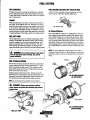
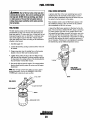
Air Cleaner/Silencer
SomeUNNERSAL engines use a replaceable air filter element Wrapped around a metal canister. 1bis element can he
removed' and brushed off or cleaned with an air hose. When
it become too contaminated it can he replaced. The canister
with its interiQr element should also be removed and cleaned
periodically. Simply wash the assembled unit in a non-flammable cleaning solvent. Use this same cleaning procedure for
other UNIVERSAL air cleaners that use a similar type canis-
FUEL LIFT PUMP
The on-engine fuel system is virtually self priming. Under
ordinary circumstances the engine's electric fuel lift pump,
which is energized by the key switch/preheat bulton, will "
supply a continuous flow of fuel from the tank. This fuel is
drawn through the fueVwater separator to the engine lift
'pump, the primary spin-on fuel fIlter, and the injection pump.
A
ter.
NOTE: To operate efficiently a diesel engine must intake a
continuous volume of clear air. Hard starting, an erratic idle,
and black exhaust smoke are all symptoms of a restricted air
intake.
WARNING: 0" not allow smoking or open flames
II/IaI filii tuBI system
when stmllclng. Also provide
proper wmtIlatlon.
FUEL SYSTEM BLEEDING
. If it becomes necessary to bleed air from the on engine fuel
system, tum the panel key ON and intennitently 5- 10 seconds. Activate the pre-hear vircui!. This activates the fuel
pump which draws fuel into the on engine fuel system and
drives air out via the fuel return.
If high pressure injector lines need to be bled, loosen the
injector line nut at each injector, open the throttle and crank
the engine over until fuel sports from between the nut and
line. the secure the nuts and start the engine as normal.
AIR CLEANER/SILENCER
IM-35B SHOWN)
NOTE: Do 'not attempt this procedure on a hot engine.
A
WARNING: Always wear p!otectlvB clothing,
samty glasses and gloves when blBBdlng high pressure
injector/lnes.
TO FUEL
ELEMENT
AIR CLEANER/SILENCER
IM-50B SHOWN]
19
FUEL SYSTEM
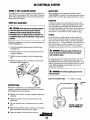
FUEL WATER SEPARATOR
AWARNING: Shut off tho fuel valvo at tho tank whlln
A primary fuel filter of the water separating type must be
installed between the fuel tank and the engine to remove
water and other contaminants from the fuel before they can
be carried to the fuel system on the engine.
SBtrlclng tho fU1I1 system. Tako calo In catching any fulll
that may spill. 00 NOT allow any smoking, opon flamllS
01 athol SOUICIIS of flIB neal tho fuol systllllJ whon SIllvtclng. EnsUIB proPIII vontllatlon oxists whon slIrvlclng
tho fuol system.
Most installers include a type of filter/water separator with
the installation package as they are aware of the problems
that contaminants in the fuel can cause.
FUEL FILTERS
A typical fuel filter/water separator is illustrated in this diagram. TIris is the Raycor Model 500 MA. Keep in mind that
if a water separator type filter is not installed between the
fuel supply tank and engine-mounted fuel system, any water
in the fuel will affect the fuel pump, engine filter, and injection equipment. The owner/operator is responsible for making
The fuel injection pump and the fuel injectors are precisely
manufactured and they must receive clean diesel fuel, free
from water and dirt. To ensure this flow of clean fuel, the fuel
must pass through at least two fuel filters, a fueVwater separator and the engine's spin-on fuel filter. Visually inspect,
clean, and change these filters according to the maintenance
schedule in this manual.
certain the fuel reaching the engine's injection equipment is
free of impurities. TIris process is accomplished by installing
and maintaining a proper filtration/separation system.
I. Shut fuel supply off.
2. Loosen the fuel filter, turning counterclockwise with a filter wrench.
3. Using a rag, wipe clean the sealing face on the housing
bracket so the new filter can be seated properly.
4. Lightly oil the sealing O-ring on the new filter. To reinstall, tum the filter assembly clockwise carefully until the
O-ring contacts the sealing surface of the housing bracket.
Tum 213 further with the filter wrench.
TO ENGINE
5. Thrn on the fuel and start the engine. The normal preheat
function should quickly prime the system and the engine
should start.
FUEL FILTER
WATER/SEPARATOR
NOTE: The cartridge contains fuel. Take Care not to spill it
during disassembly. Perfonn the PRIMING THE FUEL
'iYSTEM after replacing the spin-on filter.
TO FUEL PUMP
FUELFILnR
TO INJECTION PUMP
BLEED SCREW
GASKET
20
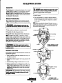
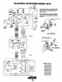
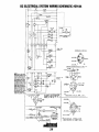
DC ELECTRICAL SYSTEM
ENGINE 12 VOLT DC CONTROL CIRCUIT
GLOW PLUGS
The engine has a 12 volt DC electrical control circuit that is
shown on the wiring diagrams that follow. Refer to these diagrams when troubleshooting or when servicing the DC electrical system on the engine.
The glow plugs are wired through the preheat solenoid.
When PREHEAT is pressed at the control panel this solenoid
should "click" on and the glow plug should begin to get hot.
Inspection
DRIVE BELT ADJUSTMENT
To inspect the plug, remove the electrical terminal connections, then unscrew or unclarnp each plug from the cylinder
head. Thoroughly clean each plug's tip and threads with a
soft brush and cleaning solution to remove all the carbon and
oil deposits. While cleaning, examine the tip for wear and
burn erosion; if it has eroded too much, replace the plug.
A
CAUTION: Drive belts must be properly tensioned.
Looss drille belts will not provide proper alternator
charging and will eventually damage the alternator.
DrllIB belts that are too tight will pull the alternator out
of alignment and/or cause the alternator to wear out prematurely.
Testing
An accurate way to test glow plugs is with an ohmmeter.
Touch one prod to the glow plug's wire connection, and the
other to the body of the glow plug, as shown. A good glow
plug will have a 0.7 - 0.8 ohm resistance. This method can be
used with the plug in or out of the engine. You can also use
an ammeter to test the power drain (8 - 9 amps per plug).
Belt tension adjustment is made by pivoting the alternator on
· its base mounting bolt.
1. Loosen the alternator adjusting strap bolt and the base
mounting bolt.
.
A
WARNING: These glow plugs will become very
hot to the touch. Be careful not to bum your fingers
when testing the plugs.
2. Pivot the alternator on the base mounting bolt to the left
or right as required.
3. Tighten the base mounting bolt and the adjusting strap
bolt.
Re-install the plugs in the engine and test them again. The
plugs should get very hot (at the terminal end) within 7 to 15
seconds. If the plugs don't heat up quickly, check for a short
circuit. When reinstalling the glow plugs, use anti-seize
compound on the threads.
4. Operate the engine for about 5 minutes at idle, then shut
down and recheck belt tension.
/'<~
A
WARNING: 00 not keep a glow plug on for more
than 30 seconds.
GLOW PLUG TIGHTENING TORQUE:
7 ·11 Ft·lb (1.0· 1.5 m·kg)
TERMINAL
END
BATTERY CARE
Review the manufacturer's recommendations and then
establish a systematic maintenance schedule for your engine
starting batteries and house batteries.
•
Monitor your voltmeter for proper charging during engine
operation.
•
Check the electrolyte level and specific gravity with a
hydrometer.
•
Use only distilled water to bring electrolytes to a proper
level.
•
Make certain that battery cable connections are clean and
tight to the battery posts (and to your engine).
•
Keep your batteries clean and free of corrosion.
TIP
TESTING AGLOW PLUG
WITH AN OHMMETER
21
DC ELECTRICAL SYSTEM
DESCRIPTION
A. WARNING: Before stattlng the engine make cettain
The charging system consists of an alternator with a mounted
voltage regulator, an engine DC wiring harness, a mounted
DC circuit breaker, and a battery and connection wires.
Because of the use of integrated circuits (lC's) the electronic
voltage regulator is very compact and is mounted internally
or on the back of the alternator.
that everyone is clear of moving paris! Keep away from
sheallBS and belts during test procedures.
5. Start the engine.
6. The voltage reading for a properly operating alternator
should be between 13.5 and 14.5 volts. If your alternator
is over- or undercharging, have it repaired at a reliable
service shop.
Alternator Troubleshooting
Hyou suspect that the alternator is not producing enough
voltage to charge the engine's battery, check the following:
NOTE: Before removing the alternator for repair, use your
A WARNING: A failtld IJItBIJIatDr can be_
voltmeter to ensure that 12 volts DC excitation is present at
the R terminal if the previous test showed only battery voltage at the B output terminal.
VfIfY
IirIt. 110 /lilt trnu:II untilllltl aItemator has cooled down.
o Make certain your alternator is securely mounted.
o Check the drive belts for proper tension.
o Inspect for loose or disconnected wires at the alternator.
.rE: An isolotor with a diode, a solenoid, or a banery
stlector switch is usually mounted in the circuit to isolate the
boIteries so the sIDrting battery is not discharged along with
tire house batteries. If tire isolotor is charging the starting
battery but not the hause battery, the alternator is OK and
tire probkm is in the battery charging circuit
'14 PINK/BlUE
A
WARNING: ShIIt off IIItI engine battery swltt:h Of
"'__ur:tt""" IIItI battery when WlHfring DR the engine
,"cfJtat SJISfIm.
TYPICAL UNIVERSAL 51 AMP
ALTERNATOR CONNECTIONS
.14 'RO"N==9"'«~--
Cllacldll far Proper Voltage
Hyou suspect the alternator has failed perform the following
tests with the engine off:
1. Using a voltmeter, connect the voltmeter red wire clip to
the output terminal B+.
2. Connect the volbneter negative wire to any ground on the
engine.
3. Check the battery voltage. It should read 12 to 13 volts.
4. Check the voltage between the alternator (+) positive terminaI B and any engine ground. If the circuit is good, the
voltage at the alternator should be the same as the battery
(unless there's an isolator in the circuit, then the reading
would be zero).
R""'I:\J[li!§
'14 PINKIBLUE
'14 BROWN
A CAUTION: To arrIId damage to tIHJ battery t:hBlging
dn:tIIt, sIuIt off IIItI engine battery switch when
fair . . . . Is I'IIIIIIlng!
'10 RED
=~=Ii~
OPTIONAL 72 AMP
ALTERNATOR CONNECTIONS
22
DC ELECTRICAL SYSTEM WIRING DIAGRAM #39144
These diagrams illustrate the 12 volt negative ground
electrical circuit. The two oplionallnslrumenl panels,
the CAPTAIN PANEL and the ADMIRAL PANEL are
diagramed below.
When an ADMIRAL PANEL Is Installed, two additional
Instrument sendors are assembled 10 the engine to
provide data lor the panel gauges (refer to the iIIustra·
lions below).
r----
,
,,,'~'-'*
REMOVE THE PLUG AND SCREW
IN THE SENDER
~
,,
'1-"=:'.
~
~
+
•
rl VDC
PLUG
b I f ! eUHfS
'="
IillW
ATTACH THE SPARE WIRE
FROM THE HARNESS BUNDLE
ADMIRAL
PANEL
REMOVE THE PLUG AND
INSTALL THE OIL TEMP SENDER
-,,
CAPTAIN
PANEL
,,
*
NOTE: An on-off switch
should be installed in this
circuit to disconnect the
starter from the battery in
an emergency and when
leaving the boat. Twelve
volt diesel engine starters
typically draw 200 to 300
amps when cranking. A
switch with a continuous
rating of 175 amps at 12
vac will normally serve
this (unction, but a switch
must never be used to
"make" the starter circuit.
23
DC ELECTRICAL SYSTEM WIRING SCHEMATIC #39144
n~u
~Ol.
+) 12 yOt
,r-,,
, ,
-
ITARlU
M
.. _-----------
L._ "
U(HUT
r -
.
-I SOl.
~''
UQI'LUU
L __
~91l':
K
AU(UUO.
:Gi'\
/'
".
c.••
,
P
!nu
'UlL
$~L.B- ~.!.'!..!. -
"" , ·•" ~
i- I
'UII'
ufT
•
,Mi:~~
•. t.,;:;'
anon
~
lI.f.
, ... lTeM
-_ .. _-----..
\C1
~
}
,,:j - - .i7.1,:j' Pi-I.i:", -
- ,i7,,-;,:;
t'j.'.i7, 'l·iI -
I
~~"
'"
n.
- - - - -
-l~
,,:'i -
ADMIRAL
PANEL
fAO~:
HITSlJ81SNI
50 AMP AI T
J
:D::o
J1-
---
0+ A~AU
STAIf
n,
j
~
I'. In
~WI;U~'f
,
.~o
'--"'"
I
.n
PU"[Af
PR[STOLIT[\L[[C[-N[Vlll[ 90 AMP. ALT.
'-"'"
~vHeK
PH
.14 GRA
uun
~'
I
•• D
"., PH""
'1-11
'H"l'II""
NOTE: An on-off switch
should be installed in this
circuit to disconnect the
starter from the battery in
an emergency and when
leaving the boat. Twelve
volt diesel engine starters
typically draw 200 to 300
"
n.
'"
Al1.
,~,
K fA>
"
n
.
$''''
amps when cranking. A
switch with a continuous
:
(I.,.
~
V.f.
lAM'
,~,
..
..
"
.1. UN
CAPTAIN
PANEL
lAM'
Tur
~4 O.
n
,
..
IN:~ \~~~
_14 LT. 8LU
,):
rating of 175 amps at 12
VDC will normally serve
this function. but a switch
must never be used to
•
"make" the staner circU/"l,---::--:-:7::--",-=_==_ _---c'7--:-=:-...,,~"""===__t
5 I AMP
.. ~ u .• ~~
11111
ALTERNATOR
STANOARD ALTERHATOR Oil THE
f~:e~. ~tC
Hffc
i±~
IY.
IIze IY,
_lOR D
® PRfSTOL
J
TE
72 AMP
.14 BRN
114 GRA
~r"'-'I!'r
,
M.
.J t!!J !
L!.J
.14 PINK
.. UD
','/AU\T,'.'t 1",'NN..,~'s·» '9
®UNIVERSAL PROPUlSION
PRESTOI I TE 5 I AMP
AI T
o
24
AI T
1-____________________
WIRING DIAGRAM CATALINA YACHTS #200360
!GS
PREHEAT
SOl EMO I Q I~,......j~__,
LIFT PIIMPS
BATTERY SWITCH*
- ':i}---f---<D
CIRCUlI
BREAKER
*theAn on·oll
swllch should be inslalled between Ihe ballery and
starter to dlsconnecllhe baHery In an emergency and
when leaving Ihe boal. Aswitch wllh a conlinuous raling 01
175 amps al12 voliS will ,erveIhe funclion. Thl, swllch
should not be used 10 make or break Ihls clreull.
• r4
z.
U
~
tl~
.14 IT. BlU
<
GRA
(NOT USEO?<
IJ( PINK
~
lIE
72 AMP
AI I
~
~
~
i
~
~
~
~
~
~
;;
g
0 PRESTOI
Z
U
~
w
110 REO
%
~
~
~
II ( 8RN
0
0
::
~
%
0
z
u
~
w
;;
g
~
~
0
Z
~
z
~
~
~
~
~
~
0
%
~
w
w
~
~
w
W
~
~
~
~
<
~
~
~
~
~
~
N
~
~
~
~
~
%
%
..
..:
~
0
,;
~
::
~
~
<
~
<
<
~
~
0
0
,;
~
~
~
g g
25
~
~
0
%
~
::
w
W
~
-
~
U
~
"""""
g
~
~
~
~
~
w
z
u
~
~
~
g g
z
u
~
~
0
~
w
~
~
w
N
N
~
~
• t 4 eRI(
~
<
.,0 RED
~
<
~
~
w
Z
0
z
~
~
~
g
Z
~
g
GRA
w
z
AI TERNATQR
g
51A MANDO
WIRING SCHEMATIC CATALINA YACHTS #200360
ST ARTE R
SOLENOID
12 VDC
+
I
I
I
I
I
I
1_
-
STARTER
r---l
M
.1
I
I
L ___ J
PREHEAT
SOLENOID
r---l
I
II
II'
s!
GLOWPLUGS
I
I
I
I
I
L ___ JI
RESISTOR
IK
CD
IIZW
AL TERNATOR
OUTPUT
r -;1
LoJ
LoJ
~
""
<r-r.
I a.:~
Ie
1"10
1<
IL
l_
loll
I
,
c:
c:
~~I(
"101
II
('
""
<,. .L-f-l
NG
"
..."
0-
-:::>
c:
U
-
-c:
U
v
LIFT PUMP
P
<n
<no::
WATER TEMP.
LoJU
C:I-
c..-
S~ER
-0--''''
\(J
~
WATER TEMP.
SWITCH
TO
TNt or
'"
T[ ....
_UnlTeli
10 TNt
nUT
SIITCH
TO Tilt'S'
H"M. or
~(TS."(H
10 TNt ",
TUM, or
(USllTtll
TO 1M( ','
TEIII. or
TH( AlAIN
BUlUII
TO TN[ .,.
TUM, or
THE AU.II
8UZZU
TO lM[ '5'
TUN. Of
THE TACH
••Unlvarsal
MARINE POWER
26
10 TNt'S'
TUM.
or
'.1. GUlIH
TO TNE 'C'
TEIIM.
or
TilE AlARli
BUZZER
TO THE fACM
OllOllKO
_ L..
ENGINE ADJUSTMENTS
. -.. ~
. NOTE: UNIVERSAL recommends thanhe following engine
~adjustments be peiformed by a competent engine mechanic.
The information below is provided to assist the mechanic.
THROnLE ANO STOP CONTROLS
Remove the valve rocker cover to expose the engine's valve
train. Remove the glow plugs from each of the cylinders to
enable the engine to be easily rotated by hand to position
each cylinder for valve adjustment.
Valves are adjusted with the piston in the cylinder being
adjusted at TOC (Top Dead Center) of its compression
stroke. Each cylinder is adjusted following the engine's firing
order.
FIRING OROER
,
•
Watch the timing hole in the bell housing for timing numbers
to appear. Position the ITC Mark in alignment with the notch
in the timing hole. The piston in Cylinder #1 is now at TOC.
Adjust the valves in Cylinder #1. Proceed to the next cylinder in the firing order.
THROTTLE
LEVER
THROTTLE
CONTROL
1-2-3
1·3-4-2
Adjust the valves beginning with Cylinder #1. Rotate the
crankshaft slowly and observe the operation of the valves for
Cylinder #1. Watch for the intake valve to open indicating
the piston is on its intake stroke (the piston is moving down
in the cylinder). Continue to rotate the crankshaft slowly and
look for the intake valve to close. The piston is now starting
its compression stroke (the piston is moving up in the
cylinder towards TDC).
MOOEL M3-20B
THROTTLE LEVER' .
3 CYLINOER MODELS
4 CYLINDER MODELS
Three Cylinder Models
Rotate the crankshaft 240' in the normal direction of rotation
and adjust the#2 cylinder's valves. Rotate the crankshaft
another 240' and adjust the #3 cylinder's valves.
MODELS M-2SB, M-3SB
Four Cylinder ModelS
Rotate the crankshaft 180' in the nmmal direction of rotation
and adjust the #3 Cylinder's valves. Rotate the crankshaft
another 180' and adjust the #4 Cylinder"s valves. Rotate the
crankshaft another 180' and adjust the #2 Cylinder'S valves.
MODEL M-SOB
SOME MOOELS
HAVE A COVER
OVER THE
HOLE
~0
THROrnE AND STOP ASSEMBLY
The throttle and engine stop levers are located on the outboard side of the engine just below the fuel injection pump.
Brackets are provided for owner-installed push-pull cables
that run to the steering station. The throttle high speed
adjustment has been factory set and is wire locked. The throttle idle screw is adjustable. These levers and brackets should
be periodically lubricated and checked for loose fastenings.
VALVE CLEARANCE
VALVE CLEARANCE
,,=,,=.=!=t
NOTE: Valve adjustment should not be necessary under
normal operating conditions. These adjustments, when
required, should be peiformed by an authorized mechanic.
27
(COLO ENGINE(
0.0071 ·0.0087 tN
[0.18 - 0.22mml
M·5DB
0.0057 - 0.0072 IN
10.145 - 0.185mml
M3·20B, M·25XP8
M-358, M·40B
ENGINE ADJUSTMENTS
NOTE: UNIVERSAL recommends that the following engine
adjustments be performed by a competent engine mechanic.
The infonnation below is provided to assist the mechanic.
TESTING ENGINE COMPRESSION
NO!IMAI,LYI?PEIV 5 PSI RAfEO
LIFT PUMP
+
Make certain the oil level (dipstick) is at the correct level and
the air intake filter is clean. The battery and starter motor must
also he in good condition.
BATTERY
1. Warm the engine to normal operating temperature.
2. Move the control lever to a position for shutting off the fuel.
(Disconnect the wires if a fuel shutdown solenoid is used).
GROUND
...
3. Remove all the glow plugs from the engine and install the
compression gauge/adapter combination to the cylinder on
which the compression is to be measured.
OIL PRESSURE
Testing Oil Pressure
To test the oil pressure, remove the oil pressure sender, then
install a mechanical oil pressure gauge in its place. After
warming up the engine, set the engine speed at idle and read
the oil pressure gauge.
MEASURING
COMPRESSION
OIL PRESSURE
7 psi (49 KPal alldle speed.
SENDER AND SWITCH TORQUE
9 ·13 R·lh (1.2 ·1.8 m • kg).
DIAL GAUGE
OIL GALLERY
IM-50B SHOWN]
~
4. Close the raw water seacock (thru-hull).
5. Crank the engine and allow the gauge to reach a
maximum reading. Record the reading.
6. Repeat this process for each cylinder.
COMPRESSION PRESSURE 412 • 469 psi 12.84·3.23 MPal at
cranking speed.
FUEL INJECTORS
MAXIMUM PERMISSIBLE DIFFERENCE BElWEEN CYLINDERS IS 10%
OR LESS. LIMIT 327 psi 12.25 MPal
In case of severe vibrations and detonation noise, have the
injectors checked and overhauled by an authorized fuel
injection service center. Poor fuel quality, contaminants and
loss of positive fuel pressure to the injection pump can result
in injector faults. Since fuel injectors must be serviced in a
clean room enviroment, it is best to carry at least one extra
injector as a spare should a problem occur.
NOTE: If the readings are below the limit, the engine needs an
overhaul.
7. Re-installthe glow plugs (use anti-seize compound on
the threads) and reset the fuel shut-off to the run position.
S. Open Ibe raw water soacock (lbru-hull).
Before removing the old injector, clean the area around the
base of the injector to help prevent any rust or debris from
falling down into the injector hole. If the injector will not lift
out easily and is held in by carbon build-up or the like, work
the injector side-to-side with the aid of the socket wrench to
free it, and then lift it out.
OIL PRESSURE
The engine's oil pressure, during operation, is indicated
by the oil pressure gauge on the instrument panel. During
normal operation, the oil pressure will range between 40 and
60 psi (2.8 and 4.2 kg/cm').
The injector seats in the cylinder head on a copper sealing
washer. This washer should be removed with the injector,
replace with a new washer when the new injector is installed .
INJECTOR TO CYLINDER HEAD TORQUE
±4 R·lh (5.5 ±0.5 kgl·m)
NOTE: A newly staned, cold engine can have an oil pressure
reading up to 60 psi (4.2 kg/ctri'J. A warmed engine can have
. an oil pressure I~ading as low as 35 psi (2.5 kg/cm' J. These
readings will vary depending upon the temperature of the
engine and the rpms.
Low Oil Pressure
FUEL INJECTOR
The specified safe minimum oil pressure is 5 - 10 psi. A
gradual loss of oil pressure usually indicates a worn bearings.
For additional infonnation on low oil pressure re~dings, see
the ENGINE TROUBLESHOOTING chart.
• .Unlvarsal
28
ENGINE TROUBLESHOOTING
The following trouble shooting chart describes certain problems, the probable causes of the problems, and the recommendations to overcome the problems.
Problem
Key switch on, PREHEAT switch
depressed: no panel indications;
fuel solenoid or electrical fuel pump
Key switch on, PREHEAT switch
depressed: START switch depressed;
no starter engagement.
Engine cranks. but does not
start.
Engine can't be stopped.
Probable Cause
Verification/1lemedy
1. Battery Switch not on.
1. Check switch and/or battery connections.
2. 20-Amp circuit breaker tripped.
2. Reset breaker, if breaker trips again, check preheat solenoid
circuit and check circuit for shorts to ground.
3. to-Amp breaker tripped.
3. Check voltage at and after breaker.
4. Loose battery connections.
4. Check (+) connection to starter solenoid and (-) connection to
engine ground stud. Check battery cable connections.
5. Preheat solenoid not operating.
5. Check solenoid.
1. Connection to solenoid faulty.
1. Check connection at solenoid.
2. Faulty START swfich.
2. Check switch with ohmmeter.
3. Faulty solenoid.
3. Check that 12 volts are present at starter solenoid activation
connection.
4. Loose battery connections.
4. Check (+) connection to starter solenoid and (~) connection to
engine ground stud. Check battery cable connections.
5. Low batteries.
5. Check battery charge state.
1. Faulty fueling system.
1. Check that fuel valves are open.
2. Preheat solenoid faulty.
2. Check solenoid.
3. low compression.
3. Compression test the engine.
1. Faulty shut-off lever at engine.
2.
Engine stops.
NOTE: The engine~ electrical system is protected by a 20Ampere manual reset circuit breaker located on the bracket
on the left side of the engine. The preheat solenoid is
mounted on the same bracket.
Push~pull
shut·off cable from steering
station to engine disconnected.
1. Reconnect shut off lever
2. Reconnect
push~pull
cable.
1. Fuellifl pump failure.
1. Fuel lift pump should make a distinct ticking sound. Replace
pump with spare.
2. Switches and/or wiring loose
or disconnected.
2. Inspect wiring for short circuits and loose connections.
Inspect switches for proper operation.
3. Fuel starvation.
3. Check fuel supply, fuel valves, fuel lift pump.
4. 20 Amp circuit breaker tripping.
4. Check for high DC amperage draw during operation.
Ensure breaker is not overly sensitive to heat which would
cause tripping.
5. Exhaust system is restricted.
5. Check for blockage, col~psed hose. carbon buildup at
exhaust elbow.
6. Water in fuel.
6. Pump water from fuellank(s): change filters and
1. Alternator drive.
1. Check drive belt tension. Aternator should turn freely. Check
for loose connections. Check output with voltmeter. Ensure 12
volts are present at the Exc terminal.
bleed fuel system.
Battery not charging
29
ENGINE TROUBLESHOOTING
Probable Cause
l'1li111_
Battery runs down.
Verillcatlon/Remedy
1. Oil Pressure switch.
1. Observe if gauges and panel lights are activated when engine is
not running. Test the oil pressure sWitch.
2. High resistance leak to ground.
2. Check wiring. Insert sensitive (0 - .25 amp)meter in battery lines.
(00 not start engine.) Remove connections and replace after short
is located.
Engine overfleats.
IIOl!: Shut engine down
immed~te\y.
3. Low resistance leak.
4_ Altemator.
3. Check all wires for temperature rise to locate the fault.
5_ Poor battery connections.
5. Check cable connections at battery.
1. Raw water not circulating.
1. Broken or loose belt at raw water pump.
2. Coolant not circulating.
2. Raw water pump failure. Check impeller - replace.
4. Disconnect altemator at output, after a good battery charging. If
leakage stops, remove alternator and bench test. Repair or replace.
2a. Obstruction at raw water intake or raw water filter.
2b. Thennostat - remove and test in hot water.
Replace thermostat.
20. Loss of coolant ~ check hoses, hose clamps, drain plug, etc. for
leaks.
2d. Broken or loose belts - tighten/replace.
2e. Air leak in system; run engine and open cooling system petcocks,
heat exchanger, manifold, etc. to bleed air. Add coolant as needed.
Exhaust smoking problems
1. Incorrect grade of engine oil.
1. Bluesmoke.
la. Crankcase is overtilled with engine oil (oil is blowing out through
the exhaust).
2_ White smoke,
2. Engine is running cold.
3_ Black or gray smoke.
3. Improper grade of fue\.
28. Faulty injector or incorrect injector timing.
3a. Fuel bum incomplete due to high back pressure in exhaust Or
insufficient air for proper combustion (Check for restrictions in
exhaust system; check air intake).
3b. Improperly timed fuel system, misadjusted valves or poor
compression.
3c. lack of air - check air intake and air filter. Check for proper
ventilation.
3d. Ove noad.
3•. Propeller.
Transmission will not shift in or out
of gear, or drive the vesse\.
1. Transmission failure.
la. Check cable connections at steering station and at
transmission lever.
lb. Check transmission fluid.
le. Check shaft couplings or engine damper plate.
ld. Check engine's damper plate.
Excessive vibration
1. Faulty engine alignment
1. Check the shaMransmission coupling.
2_ Cutless beanngs, support strut and
2. Inspect propeller and shaft.
1a. Inspect all engine mounts.
propeller could all be suspect.
30
CONTROL PANEL TROUBLESHOOTING
MANUAL STARTER DISCONNECT (TOGGLE SWITCHES)
NOTE: The engine control system is protected by a 20 amop manual reset circuit breaker
located on the engine as close as possible to the power source.
Probable Cause
Problem
Verificallon/Remedy
PREHEAT depressed. no panel indications
fuel solenoid, electric fuel pump and
preheat solenoid not energized.
1. Oil Pressure switch.
1. Check switches and/or battery connections.
2. 20 amp circuil breaker tripped.
2. Reset breaker. If opens again, check preheat solenoid circuil
START SWITCH DEPRESSED. no starter
1. Connection to solenoid faulty.
1. Check connection.
2. Faulty switch
2. Check switch with ohmmeter.
3. Faulty solenoid.
3. Check that 12 volts are present at the solenoid connection.
4. Loose battery connections.
4. Check battery connections.
and run circuit for shorts to ground.
engagement.
NO tGNITION. cranks. does not start.
NOT CHARGING BATTERY
5. Low batteI)'.
5. Check battel)' charge state.
1. Faulty fueling system.
1. Check for fuel.
2. Check for air in the fuel system.
2. Allow system to bleed.
3. Faulty fuel lift pump.
3. Replace fuel lift pump.
1. Faulty alternator drive.
1. Check the drive belt and its tension. Be sure the alternator
turns freely. Check for loose connections. Check the
output with a voltmeter. Ensure 12V are present at the
regulator terminal.
BATTERY RUNS DOWN
1. Oil pressure switch.
1. Observe if the gauges and panel lights are activated when the
engine is not running. Test the oil pressure switch.
2. High resistance leak to ground.
2. Check the wiring. Insert sensitive (0-.25 amp) meter in bat1ery
lines (Do NOT start engine). Remove connections and replace
after short is located.
3. Low resistance leak to ground.
3. Check all wires for temperature rise to locate the fault.
4. Faulty alternator.
4. After a good bat1ery charging, disconnect alternator at output.
If leakage stops. Remove alternator and bench test. Repair or
replace.
ALARM BUllER SOUNDING
1. Resistor shorting.
1. Check resistor 1000 ohm. resistor found between preheat
solenoid "I" terminal and ground.
(Oil pressure nonnal)
2. Fuel pump.
2. Fuel pump coils shorting.
3. Oil pressure switch.
3. Oil pressure switch internal contacts not closing properly.
TROUBLESHOOTING WATER TEMPERATURE AND OIL PRESSURE GAUGES
If the gauge reading is other than what is nonnally indicated
by the gauge when the instrument panel is energized, the first
step is to check for 12 volts DC between the ignition (B+)
and the Negative (B-) tenninals of the gauge.
If both of the above gauge tests are positive, the gauge is
undoubtedly OK and the problem lies either with the
conductor from the sender to the gauge or with the sender.
If either of the above gauge tests are negative, the gauge is
probably defective and should be replaced.
Assuming that there is 12 volts as required, leave the
instrument panel energized (key switch on) and perfonn the
following steps:
Assuming the gauge is OK, check the conductor from the
sender to the sender tenninal at the gauge for continuity.
1. Disconnect the sender wire at the gauge and see if the
gauge reads zero, which is the nonnal reading for this
situation.
Check that the engine block is connected to the ground.
Some starters have isolated ground tenninals and if the
battery is connected to the starter (both plus and minus
tenninals), the ground side will not necessarily be connected
to the block.
2. Connect the sender terminal at the gauge to ground and
see if the gauge reads full scale, which is the nonnal reading
for this situation.
31
TACHOMETER
TACHOMETER/HOUR METER
The tachometerlhour meter used in propulsion engine instrument panels contains two separate electrical circuits with a
common ground. One circuit operates the hour meter and the
other the tachometer. The hour meter circuit operates on 12
volts alternator charging voltage supplied to the (+) terminal
on the back of the instrument.
The tachometer circuit operates on AC voltage 6-8 volts, fed
from one of the diodes in the alternator and supplied to the
tachometer input terminal while the engine is running, and
the alternator producing battery charging voltage 13.0-14.8
volts DC.
The following are procedures to follow when troubleshooting
a fault in either of the two circuits in a tachometerlhour
meter.
NOTE: Current model tachometers use a coarse adjustment
dial to set the tachometer to the crankshaft pulley rpms. The
calibrating screw is then used for fine tuning.
CURRENT
WIRE
TERMINAL
CDARSE
ADJUSTMENT
Hour meter Inoperative
Check for the proper DC voltage between (+) and (-)
terminals.
1. Voltage present - meter is defective - repair or replace.
2. Voltage not present - trace (+) and (-) electrical connections for fault. (Jump 12 volts DC to meter (+)
tenninal to verify the operation.)
Tachometer Inoperative
Check for the proper AC voltage between tachometer input
tenninal and (-) tenninal with the engine running.
1. Voltage present - attempt adjusting meter through calibration access hole. No results, repair or replace meter.
2, AC voltage not present - check for proper alternator DC
output voltage.
3. Check for AC voltage at tach tenninal on alternator to
ground.
4. Check electrical connections from tachometer input terminal to alternator connection.
Tachometer Sticking
1. Check for proper AC voltage between "tach inp." terminal and (-) terminal.
2. Check for good ground connection between meter (-) terntinal and alternator.
IDLE SPEED ADJUSTMENT
& TACHOMETER CHECK (New Installation)
Checking the idle speed
NOTE: In a new installation having new instrument panels,
the tachometer may not always be correctly calibrated to the
engine's rpm. This calibration should be checked in all new
installations.
1. Wann up the engine to nonnal operating temperature.
Remove any specks on the crankshaft pulley with a clean
cloth and place a piece of suitable reflecting tape on the
pulley to facilitate use of a photoelectric type tachometer.
2. Start and idle the engine.
3. Aim the light of the tachometer onto the reflecting tape to
confinn the engine speed. Check the instrument panel
tachometer reading. Adjust the tachometer in the panel by
using the instrument coarse adjustment to calibrate the
instrument reading to the closest R.P.M. that the photo tach
is showing. Then use the fine calibration adjustment to
bring the instrument to the exact reading as the photo tach.
4. Adjust the idle speed if the engine speed is not within the
specified value.
NORMAL IDLE SPEED:
3. Check that alternator is well grounded to engine block at
alternator pivot bolt.
MODEL
Tachometer Inaccurate
M3-20B
M25XPB
M35B
M40B
M50B
a. With a hand-held tach on the front of the crankshaft
pulley retaining nut or using a strobe type tach, read the
front crankshaft pulley rpm at idle.
b. Adjust the tachometer using an 2mm Allen head wrench
1164 (2mm) through the calibration access hole in the rear
of the tachometer. Zero the tach and bring it to the rpm
indicated by the strobe or hand tach (verify rpm at idle
and at high speed). Adjust the tach as needed.
RECOMMEIIIED RPM IWIGES
CRUISE
IDLE
RPM
RPM
2500
- 3000
1000 - 1200
2000 - 2500
1000 - 1200
2000 - 2500
800-1000
2000 - 2500
800 -1000
2000·2500
800 - 1000
MAXIMUM
RPM
3500 - 3600
2900·3000
2900 - 3000
2900 - 3000
2700 - 2800
NOTE: Attempting to reduce idle speed below the minimum
shown may produce unstable engine operation and stalling.
32
WATER HEATER CONNECTIONS
WATER HEATER INSTALLATIONS
The pressure cap on the engine's manifold should be
instalJed after the engine's cooling system is filJed with
coolant. Finish filling the cooling system from the remote
tank after the system is filled and is free of air and exhibits
good coolant circulation. DUling engine operation, checking
the engine's coolant should be done at the remote lank and
not at the engine manifold cap. The hose connection from the
heater to the remote expansion tank should be routed and
supported so it rises continuously from the heater to the tank,
enabling any air in the system to rise up to the tank and out
of the system.
This engine is equipped with connections for the plumbing of
engine coolant to heat an on-board water heater. The water
heater should be mounted in a convenient location either in a
high or low'position in relation to the engine, so that the connecting hoses from the heater to the engine can run in a reasonably direct line without any loops which might trap air.
Hoses should rise continuously from their low point at the
heater to the engine so that air wiII rise naturally from the
heater to the engine. If trapped air is able to rise to the heater,
then an air bleed petcock must be installed at the higher fitting on the heater for bleeding air while filling the system.
NOTE: Air bleed petcocks are located on the engine's heat
exchanger and on the thennostat housing. Open these petcocks when filling the engine's fresh water system to allow
air in the coolant cin:uit to escape. Close tightly after all the
air is removed.
NOTE: If any ponion of the heating circuit rises above the
engine:r closed cooling system pressure cap, then a pressurized (aluminum) remote expansion tank (Kit #024177) must
be installed in the circuit to become the highest point. Tee the
remote expansion tank into the heater circuit, choosing the
higher of the two connections for the retum. Tee at the
heater, and plumb a single line up to the tank's location and
the other back to the engine s return. Install the remote
expansion tank in a c.ollvenient location so the fresh water
coplant level can easily be checked. The remote expansion
.tank will now serve as a check and system fill point. The
plastic coolant recovery tank is not used when the remote
expansion tank kit is installed, since this tank serves the same
function.
~ TfIERMIOST.ITHOUSING
HEATER BELOW THE ENGINE
WATER
HEATER
HEATER ABOVE THE ENGINE
WATER
HEATER
HOSE CONNECTIONS
The hose adapters (nipples) coming off theengine
(thermostat housing and water pump housing) are sized
for 3/8" J.D. hose. An adapter is available (#302391) that
will increase the size to 5/8" J.D. hose.
NOTE: The remote expansion tank
is for filling and the expansion of
coolant. Water heater coolant flow
need not go through the tank.
33
ADAPTER PN 302391
PRM NEWAGE TRANSMISSIONS
~
MODELS 80 AND 120
THE MODEL 120 HAS A BREATHER
FITTING ON THE TOP OF THE CASE~
SERIAL NUll/BEl!.
NOTE: When changing the fluid, take care not to lose the
drain plug sealing washer. The drain plug will leak without
this sealing washer.
1/2" HEX PLUG
MODEL 80 (MODEL 120 USES
A BMM HEX PLUG)
---_""POI·lrK
PRM 8DI_.q;~e
A WARNING: Never pull out the dipstick while the
engine is running, Hot "uid will splash from the
dipstick hole. This could cause severe burns.
VENTS
DAILY OPERATION
o
Check the transmission fluid.
Visually check the gear shift linkage and transmission.
Start the engine in neutral, allowing a few minutes at
idle to warm the fluid.
Shift into gear.
NOTE: Too Iowan idle speed will produce a chattering noise
from the transmission gear and damper plate. In such cases
the idle speed should be increased.
o
o
o
FULL
LOW
GEAR SHIFTING
~
SEALING WASHER
NOTE: Keep ventlvent holes clear and unobstructed.
The engine must be at idle. Pause in neutral before
selecting ahead or astern, Transmission models PRM 80 and
120 are ideal for single lever controls, controlling both the
throttle and the gear shift at one time.
A
INITIAL OPERATION
WARNING: When shifting gears, bring the engine
throttle to idle and pause in neutral before shifting
ahead or astern.
Before starting the engine, remove the dipstick and fill the
transmission with automatic transmission fluid (ATF)
Dextron 11 or Dextron 111. Fill to the mark on the dipstick.
Do not overfill.
R~n the engine to warm up the fluid and after shutting down
the engine, re-check the fluid level.
Model PRM 80-1.0
U.S. pints (0.6L)
Model PRM 120-1.4 U.S. pints (0.8L)
NOTE: Always clean the area around the dipstick plug before
filling with fluid. Replace the dipstick by screwing it down
LOCKING THE PROPELLER
Locking of the propeller shaft by an additional brake is not
required. Use the gear shift lever position opposite your
direction of travel for this pUl]Jose. Never put the gear shift in
the position corresponding to the direction of travel of the
boat.
WHEN UNDER SAIL OR BEING TOWED
Rotation of the propeller without a load, such as when the
boat is being sailed, being towed or anchored in a river, as
well as operation of the engine with the propeller stopped
(for charging the battery), will have no detrimental effects
on the transmission.
CHECKING THE FLUID LEVEL
Thread the dipstick fully into the case, then unscrew it and
observe the fluid level.
CHANGING THE TRANSMISSION FLUID
Change the fluid for the first time after about 25 hours of
operation, then every 250 operating hours or at least once a
year or when you change engine fluid. Check for leaks and
make a visual inspection of the shift cables and shaft
coupling. Push a suction pump hose down through the
dipstick hole to the bottom of the housing and suck out the
fluid. (If space allows, use the transmission drain). Remove
the drain plug from the bottom of the transmission (I" with
sealing washer) and allow the fluid to drain into a container,
then reinstall the plug with its sealing washer. Wipe down the
transmission and properly dispose of the used fluid. After
running the engine, shut down and recheck the fluid level.
,\, .UnivQrsal
MARINE POWER
34
PRM NEWAGE TRANSMISSIONS
MODELS 80 AND 120
CONTROL CABLES
The control cable or rod should be arranged at a right angle
to the actuating shift lever with the lever in the neutral
position. The neutral position of the operating lever in the
cockpit must coincide with the neutral position of this lever.
The shift level travel must be such that the lever just strikes
the internal stops for the lever when shifted into forward or
reverse. Those stops can be determined by manually moving
the shift lever with the cable disconnected. This is an
important adjustment for proper engagement of the gear. If
the lever is too short, proper clutch engagement might be
impeded which, in tum, would mean premature wear,
excessive heat generation and clutch plate failure. This would
be indicated by slow clutch engagement or no engagement at
all.
NEUTRAL
N
R~~D<./~ \
, ,-,
ACTUATING /""\;0'
SHIFT LEVER
'
0
--;
'')'
I
I
/ , ' '-'_..w...'__-=:;
;';t
,/
SHIFT CABLE AND BRACKET
NOTE: Checkfor proper lever travel and the security of the
cable ta the level bracket at least each season.
MAINTENANCE/SERVICE
WARRANTY
Make certain the transmission fluid is changed annually, If
the fluid should become contaminated by water or the gearbox suffers major mechanical damage, the gearbox must be
thoroughly flushed out and re-filled with fresh fluid to the
correct specifications.
NEWAGE TRANSMISSIONS LID. has distributors around
the world. Listed here are those in the United States.
NEWAGE TRANSMISSIONS LTD. warrants that all PRM
Newage Transmissioms will be free from defects in material
and workmanship under normal use and service for a period
or 24 months.
All PRM transmissions must be correctly installed. aligned.
and maintained.
TROUBLESHOOTING
Atlantis Marine Gear Supply Inc,
418 Boston Street
Topsfield, MA 01933
Tel: 978-887-0001
Fal: 978-887-5599
See the following page.
HamlHonJet
1111 NW Ballard Way
SeaHle, WA 98107
Tel: 206-784-8400
Fal: 206-783-7323
Transmission Marine
223 Southwest 33 Cour!
P.O. BOl21086
R. Lauderdale, FL 33335-1086
Tel: 954-467-1540
Fu: 954-467-1525
Newage Transmissions, Limited.
Website: www.Newage-PRM.co.uk
If a major problem should occur. contact your WESTERBEKE
dealer or a NEWAGE distributor. To avoid prejudicing
warranty rights, do not undertake repair work on the gearbox
without first contacting NEWAGE TRANSMISSIONS LTD. or
a NEWAGE distributor (listed above) or your WESTERBEKE
dealer.
35
~.,.
PRM NEWAGE TRANSMISSIONS TROUBLESHOOTING
Problem
Probable Cause
VerlllcalionJRemedy
Excessive noise at low speeds.
1. Engine idle speed too low.
1. Increase· idling speed.
Excessive noise at aU speeds.
1. Defective coupling.
1. InspecVreplace coupling if necessary.
2. Shaft misalignment.
2. Check alignment with feeler gauge.
fluid needs constant topping off.
3. Prop out of balance.
3. Remove, check pitch, balance and weight.
1. Power too high.
1. Compare engine and transmission data.
2. fluid leak.
2. Inspect seals. O-rings. drain plug. check for fluid leaks.
Difficulty in moving lever control.
1. Poor installation of cable.
1. Check installation, remove sharp bends and turns.
2. faulty cable.
2. Replace.
Escape of pressure from gearbox
when dipstick is removed.
1. Defective breather causing leaks
past oil seals.
1. Remove dipstick/clean vent holes - PRM 80.
No drive ahead or astern.
1. Mechanical'damper plate problem.
1. Replace damper plate.
Propeller speed does not increase
with engine speed ahead and astern.
1. Shift cable.
1. Remove control cable or linkage not allowing f·N·R to
move correct distance. -Remove cable and operate lever by
hand to check movement. Adjust cable if necessary
Propeller speed does not increase
with engine speed in one direction only.
1. Cone/clutch cable slippage. Damaged.
clutch plates or clutch cones.
1. Remove and examine clutch/clutch cone on appropriate
shaft and replace if necessary.
Excessive' nOise from gearbox
at low speeds.
1. Engine idle speed set too low.
faulty adjustment.
1. Increase idling speed. If not cured by increasing idling speed,
refer to engine supplier. Remove, examine and replace
coupling if necessary.
Excessive noise throughout
operating range.
1. Oefective input coupling. Input
coupling worn/damaged.
Propeller shaft misalignment. faulty
installation or hull flexing.
1. Check the alignment of the propeller shaft coupling. If
necessary, rectify by adjusting the shims under the
engine mounts or adjust the engine mounts themselves.
2. Propeller out of balance. damaged prop.
2. Remove the propeller and check that the pitch. weight.
2. Unscrew vent assembly from top of transmission and clean
with solvent - PRM 120.
diameter and balance of all the blades are equal and reclify
if necessary.
poorly matched.
Difficulty in moving single lever control.
3. Defective bearing/bearing.
Worn or damaged.
3. Isolate defective bearing, remove and replace.
1. Operating control cable.
1. Check the installation and eliminate all tight bends in the cable.
,I, ,I,Univarsal
MARINE POWER
36
HURTH HBW/ZF TRANSMISSIONS
NOTE: When installing the transmission, make cel1ain that
DESCRIPTION
shifting is not impeded by restricted movability of the cable
or rod linkage, by unsuitably positioned guide sheaves, too
small a bending radius or other restrictions, In order to
mount a suppon for shift control cable connections, use the
two threaded holes located above the cable bracket mounted
on the gear housing. Refer to the WESTERBEKE parts list.
111e information below is specific to the HBW
Transmissions, the TRANSMISSION TROUBLESHOOTING
SECTION applies to all models.
HURTH HBW 150
ZF 15M
SHIFT LEVER
The transmission is suitable for single lever remote control.
Upon loosening the retaining screw, the actuating lever can
be moved to any position required for the control elements
(cable or rod linkage). Make certain that the shift lever does
not contact the actuating lever cover plate: the minimum
distance between lever and cover should be O.5mm.
The control cable or rod should be arranged at light angle to
the actuating shift lever when in the neutral position. The
neutral position of the operating lever on the control console
should coincide with the neutral position of this lever.
The shifting travel, as measured at the pivot point of the actuating lever, between the neutral position and end positions A
and B should be at least 35mm for the outer and 30mm for
the inner pivot point.
A greater amount of shift lever travel is in no way
detrimental and is recommended. However, if the lever
travel is shorter, proper clutch engagement might be impeded
which, in turn, would mean premature wear, excessive heat
generation and clutch plate failure. 1bis would be indicaled
by slow clutch engagement or no engagement at all.
NOTE Check for proper lever travel at least each season.
NEUTRAL
A CAUTION: The position of the mechanism behind
the actuating lever Is factory-adjusted to ensure equal
shift lever travel from neutral posit/on AandB. If
this mechanism Is In any way tampered with, the
transmission wa"anty will be void.
WESTERBEKE recommends a flexible connection between
the transmission and the propeller shaft if the engine is flexibly mounted, in order to compensate for angular deflections.
The installation of a special propeller thrust bearing is not
required, since the propeller thrust will be absorbed by the
transmission bearing. provided the value specified under
SPECIFICATIONS is not exceeded. However, the output
shaft should be protected from additional loads. Special care
should be taken to prevent torsional vibration. When using a
universal joint shaft, make certain to observe the
manufacturers instructions.
Even with the engine solidly mounted, the use of flexible
coupling or "DRNESAVER" will reduce stress in the gearbox. bearings caused by hull distortions, especially in wooden
boats or where the distance between transmission output
flange and stem gland is less than about 800mm.
Rockland, MA.
REVERSE
A
B
CONTROL
CABLE
SHAFT COUPLINGS
"Drivesavcr" is a product of Globe Marine
FORWARD
SHIFT
LEVER
COVER
,I, ,I,Univanal
MARINE POWER
37
F
O.5mm
MINIMUM DISTANCE
HURTH HBWnF TRANSMISSIONS
LOCKING THE PROPELLER
INITIAL OPERATION
All HBWIZF marine transmissions are test-run on a test
stand with the engine at the factory prior to delivery. For
- safety reasons the fluid is drained before shipment.
Fill the gearbox with Automatic Transmission Fluid
(DEXRON II or DEXTRON III). The fluid level should be
up to the index mark on the dipstick. To check the fluid level,
just insert the dipstick, do not screw it in. Screw the dipstick
into the case after the fluid level is checked and tighten. Do
not forget the sealing ring under the hex head of the dipstick.
Check for leaks and change the fluid after the first 25 hours,
also make a visual inspection of the coupling, oil cooler and
hoses, and shift cablcs.
Locking of the propeller shaft by an additional brake is not
required: use the gear shift lever position opposite your
direction of travel for this purpose. Never put the gear shift in
the position corresponding to the direction of travel of the boat.
WHEN UNDER SAIL OR BEING TOWED
Rotation of the propeller without load (in neutral), such as
when the boat is being sailed, being towed, or anchored in a
river, as well as operation of the engine with the propeller
stopped (for charging the battery), will have no
.
detrimental effects on the transmission
DAILY OPERATION
D Check the transmission fluid.
D Visually check the gear shift linkage and transmission.
d
Start the engine in neutral, allowing a few minutes at
idle to warm the fluid.
D Shift into gear.
NOTE: Too Iowan idle speed will produce a chollering liaise
from the transmission gear and damper plate. III silch cases
the idle speed should be increased
For additional infonnation refer to the following text in this
Transmission Section: SHAFT COUPLINGS. MAINTENANCE
AND TRANSMISSION TROUBLESHOOTING.
FlUID LEVEL
'. HBWJZF TRANSMISSIONS SPECIFICATloNSHli
NOTE: Keep vent holes clear.
General
Change the fluid for the first time after about 25 hours of
operation, then every 250 operating hours or at least once a
Gear ratio (oplional)
HBW 50lZF 5M (2.05 : 1)
HBW 100lZF 10M (1.79: 1)
HBW 150VIZF 15MIV (2.13: 1)
HBW 150NZF 15MA (1.88: 1)
Lubricaling Fluid
Transmission Sump
Capacity
ATF - or Dextran - /I or /II
year Of when you change engine oil.
Removing the fluid
Push a suction pump hose down through the dipstick hole to
the bottom of the housing and suck out the fluid. (If space
allows, use the transmission drain). Remove the drain plug
from the bottom of the transmission and allow the fluid to
drain into a container, then reinstall the plug with its sealing
washer. Wipe down the transmission and properly dispose of
the used fluid. After I1lnning the engine, shut down and
recheck the fluid level.
Drain plug IOTQue
(Hurth/ZF Standard Transmission) Case-
hardened helical gears, with a servooperated multiple disc clulch.
FLUID CHANGE
Propeller Rotalion
20 - 25 Mbs
NOTE: When changing the fluid, take care not to lose the
draill plug sealing washer. The drain plllg will leak without
this sea/il1g washa
A WARNING: Never pull out the dipstick while the
engine is running_ Hot fluid will splash from the
dipstick hole. This could cause severe burns.
. . .Univarsal
38
HBW 50lZF 5M
0.63pts (0.3L)
HBW 100lZF 10M
0.74pts (0.35L)
HBW 150VIZF 15MIV 2.1pts (1.0L)
HBW 150NZF 15MA 1.0pts (0.47L)
Transmissions turn Right Hand propellers
HURTH HBWJZF TRANSMISSIONS
OPERATING TEMPERATURE
MAINTENANCE
Transmission maintenance is minimal. Keep the exterior
housing clean, check the fluid level as part of your regular
routine, and change the fluid every 300 operating hours.
Periodically inspect the transmission and the cooler for leaks
and corrosion. Lubricate the cable connections.
A WARNING: If the transmission fluid temperature
is too high, stop the engineimmedlatelyand check the
transmission fluid.
Lay-up/Winterize
NOlmal operating temperature of the transmission flUId
should be in the range of 122°F (50°C) to 212"F (100°C). A
maximum temperature of 266°F (l30°C) may be only
reached for a short time.
Storage requires special care. Follow these procedures:
D
Make certain there is enough space around the transmission
to provide good ventilation and cooling.
Drain water from the transmission oil cooler and replace
with a proper mixture of antifreeze coolant.
NOTE: This operation will normally occur when the
engine raw water cooling system is properly winterized.
TRANSMISSION COOLER
Some UNIVERSAL model's transmissions are equipped
with an exlernally attached convection type transmission
cooler.
The cooler is a separate part of the transmission which
prevents any possibilities of coolant diluting the transmission
fluid. However, the continued flow of coolant thru the cooler
will, in time, erode the inside of the cooler causing external
leaks.
A transmission cooler may last ten years or more but, in
some circumstances, depending on operating hours, tropical
waters, maintenance, etc. it might only last half that time.
WESTERBEKE recommends having a spare cooler aboard.
D
Clean up the transmission and touch up unpainted areas
(use heat resistant paiot).
D
Fill the transmission with Dextran III ATF fluid to prevent "internal corrosion (extended storage only, twelve
months or more),
. D Loosen attaching hardware from the transmission output
flange and propeller shaft coupling flange before remov·
ing the boat from the water. Separate the flanges and
spray with lubricant.
D Inspect the gear shift cable, linkage, and attachments.
Look for corrosion of the end fittings, cracks or cuts in
the conduit, and bending of the actuator rods. Lubricate
all moving parts.
NOTE: If the transmission is to be stored for a long time
(twelve months or more), it should be topped off with
fluid to prevent internal corrosion. Reduce the fluid level
before putting the engine back into selVice.
For additional infonnation contact:
TIIANSMISSION
-~It.!::!.;~-" ef!.!/9.~(!q1\fX INSPECT FOR
EROSION AND LEAKAGE
HURTH MARINE GEAR
ZF Industries
Marine US Headquarters
3131 SW 42nd Street
Fort Lauderdale, FL 33312
Tel.: (954) 581·4040
Fax: (954) 581-4077
+ ;.,Unlvanal
MARINE POWER
39
HURTH HBWJZF TRANSMISSION TROUBLESHOOTING
CONTROL CABLES
The majority of transmission difficulties arise as a result of
improper clutch adjustments (manual transmissions) or
. problems with control cables (hydraulic transmissions)
rather than from problems with the transmission itself.
HURTH!ZF clutches, in particular, are very sensitive to
A new cable and perhaps a new linkage mechanism may be
needed. While the cable is loose, shift the transmission in and
out of gear using the lever on the side of the transmission to
make sure there's no binding inside the case.
If the transmission passes these tests, crank the engine and
have a helper put it in forward and reverse while you observe
the propeller shaft; if the shaft isn't turning, the transmission
needs professional attention. If it does turn but there's no
thrust, check to see you still have a propeller on the end of
the shaft or, if you have a folding or feathering propeller,
that it isn't stuck in the "no pitch" position.
improper cable adjustments.
If you experience operating problems with the transmission,
shut the engine down. First check the transmission-fluid
level, then have a helper move the cockpit shift lever through
the full range - from neutral to full forward, back to
neutral, into full reverse, and back to neutral - while you
observe the actuating lever on the transmission. If the remote
NOTE: If you suspect a major problem il1 your tra11smissioll,
immediately cOlltact your WESTERBEKE dealer or ali
authorized marine trallsmissiolljacility.
is stiff to operate, break the cable loose at the transmission
and try again. If it is still stiff, check the cable for kinks or
excessively tight bends, and check any linkage for binding.
Problem
Transmission gears cannot be shifted.
Fails to move into gear.
Transmission shifts into gear,
but fails to propel the boat.
Delay of gear engagement or engages
only after an increase in speed.
Transmission noise becomes louder.
Probable Cause
Verlficalion/Remedy
1. Actuating lever is loose.
1. Tighten damping boll on shifting lever.
2. Shifting cable is broken, bent or
unattached. Cable radius is too severe.
2. Check the cable, reattach or replace.
3. Shift lever is binding against cover plate.
3. Detach the shift cable and operate the tever by hand.
Clearance should be 0.02 in (0.5mm).
1. Output coupling is not turning.
1. Transmission needs professional attention.
2. Propeller shaft is not turning.
Output coupling is turning.
2. The coupling bolts are sheared or the coupling is slipping
on the propeller shaft. Tighten or replace set screws, keys,
pins and coupling bolts as necessary.
3. Output coupling and
propeller shaft are turning.
3. Inspect the propeller. It may be missing or damaged.
A folding propeller may be jammed. A variable pitch
propeller may be in "no pitch" position.
1. lever travel N to B not equal to N to A.
1. Adjust cover plate until the lever is exact mid-position.
Refer to SHIFT LEVER TEXT AND DIAGRAM.
Refer to diagram,
2. Shift level travel in insufficient.
2. Check shift lever cable length. See SHtFT LEVER DtAGRAM.
3. Shift lever is binding against cover plate.
3. Check clearance, adjust if necessary.
1, Damage starting on flexible coupling due
1. Check alignment, inspect flexible coupling. If noise persists,
to wear or fatigue, possibly due to
misalignment between engine and
driveshaft.
2. Beginning damage of bearings in
inspect the damper plate between the transmission and the
engine. Replace if necessary.
2. Transmission needs professional attention.
transmission due to torsional vibrations,
running without fluid, overload, wrong
alignment of transmission, or excessive
engine output.
Chattering transmission noise,
mainly at low engine speed.
1. The engine or propeller generates torsional
vibrations in the drive unit which produces
a "chattering" noise in the transmission.
1. Mount a flexible coupling with another stiffness factor
between the transmission coupling with and the driveshaft.
A higher stiffness factor might be sufficient.
2. Inspect the damper plate between the engine and the
transmission. Replace if necessary.
80at fails to attain specified max. speed.
Oil Leakage.
1. Operating temperature is high,
1. Wrong type of fluid. Use ATf. Check fluid level.
2. Operating without cooling.
2. Check cooler. Inspect coolant hoses and coolant flow.
1. Corrosion at radial sealing ring and shaft.
1. Transmission needs professional attention.
Damaged sealing ring._
2. Misalignment of output flanges.
NOTE: If )'01/ suspect a major problem ill your transmission,
'immediately contact your WESTERBEKE dealer or an
O1lfhorized marine trallsmissionjacility,
+ .Unlvarsa.
MARINE POWER
40
2. Check alignment. Must be within 0.003 in (O.OBmm).
HURTH HBW/ZF TRANSMISSION TROUBLESHOOTING
Probable Cause
Problem
High fluid temperature.
1. Fluid level high during operation.
2.
3.
4.
5.
Auid on transmission housing.
Verificalion/Remedy
Fluid level low.
Plugged or restricted fluid cooler.
No water in cooling system.
Riter clogged (if applicable).
1. loose screws.
2. Loose screw connections.
3. Loose dipslick.
Auid and water miXed, shiHs hard.
Slow engagement.
No movement of the boat.
1. Pump out fluid to the maximum and mark on dipstick.
2.
3.
4.
5.
Add fluid.
Replace cooler and flush water system.
Check cooling system and repair.
Replace element.
1. lighten to specification.
2. Tighten, replace.
3. Tighten. replace.
4. Loose fluid filter.
4. Tighten, replace.
5. Fluid level high during operation.
5. Pump out fluid to the maximum and mark on dipstick.
1. Damage to fluid cooler..
1. Replace cooler and flush transmission and hoses.
2. Selector control linkage.
2. Refer this manual.
1. Selector control.
1. Refer this manual.
2. Low Iluid level.
3. Linkage.
2. Add fluid.
3. Adjust (reler this manual.
1. Selector control.
L
2.
3.
4.
5.
6.
7.
2.
3.
4.
5.
6.
7.
Improper selector pOSition.
Low fluid level.
Propeller missing.
Propeller shaff broken.
'Transmission malfunction.
Engine mallunclion.
Consult service station.
Adjust (see this manual).
Add Iluid.
Replace.
Contact marine repair.
Contact manufacturer.
Contact marine repair.
NOTE: If you suspect a major problem in your transmission, immediately contact your WESTERBEKE dealer or all authorized
marine transmission facility.
41
LAY-UP AND RECOMMISSIONING
LAY·UP
A
CAUTION: Do not leave the engine's old engine
oil in the sump over the lay-up period_ Engine oil and
combustion deposits combine to produce harmful
chemicals which can reduce the life of the engine's
internal parts.
Many owners rely on their boatyards to prepare their craft,
including engines and generators, for lay-up during the
off-season or for long periods of inactivity. Others prefer to
accomplish lay-up preparation themselves.
The following procedures will allow you to perform your
own lay-up and recommissioning. or you may use them as a
check list for others. These procedures should afford your
engine protection during a lay-up and also help familiarize
you with the maintenance needs of your engine.
FUEL SYSTEM
Top off your fuel tanks with No. 2-D (SAE 1313) that has a
cetane rating of #45 or higher grade of diesel according to
ASTM 0975. Fuel additives should be added at this time to
control bacterial growth and a fuel conditioner such as
Diesel Kleen + Cetane Boost (DO NOT use any alohol
based additives). Change the element in your primary fuel
If you have any questions regarding lay-up procedures, call
your local servicing dealer; he will be more than willing to
provide assistance.
PROPELLER SHAFT COUPLING
filter/water separator, if the system contains one, and clean
The transmission and propeller half couplings should always
be opened up and the bolts removed when the boat is hauled
out of the water or moved from land to water, and during
storage in a cradle. The flexibility of the boat often puts a
severe strain on the propeller shaft or coupling, or both,
while the boat is taken out or put in the water. In some cases,
the shaft has actually been bent by these strains. This does
not apply to small boats that are hauled out of the water
when not in use, unless they have been dry for a considerable
period of time.
the separator sediment bowl.
Change the fuel filter elements on the engine and bleed the
system as needed. Start the engine and allow it to run for
5-10 minutes to make sure no air is left in the fuel system.
Check for any leaks that may have been created in the fuel
system during this servicing, correcting them as needed.
RAW WATER CIRCUIT
Close the through-hull fitting. Remove the raw water intake
hose from the fitting. Place the end of this hose into a
5-gallon bucket of clean fresh water. Before starting the
engine, check the zinc anode found in the heat exchanger on
FRESH WATER COOLING SYSTEM
A 50-50 solution of antifreeze and distilled water is recommended for use in the freshwater cooling system at all times.
This solution may require a higher concentration of
antifreeze, depending on the area's winter climate. Check the
solution to make sure the antifreeze protection is adequate.
the engine and clean or replace it as required. Clean the raw
water strainer, if one is installed in the inside of the hull.
Start the engine and allow the raw water pump to draw fresh
water through the system. When the bucket is empty, stop the
engine and refill the bucket with an antifreeze solution
slightly stronger then needed for winter freeze protection in
Should more antifreeze be needed, drain an appropriate
amount from the engine block and add a more concentrated
mixture. Operate the engine to ensure a complete circulation
and mixture of the antifreeze concentration throughout the
cooling system. Now recheck the antifreeze solution's
strength.
your area.
Start the engine again and allow all of this mixture to be
drawn through the raw water system. Once the bucket is
empty, stop the engine. This antifreeze mixture should
protect the raw water circuit from freezing during the winter
LUBRICATION SYSTEM
lay-up, as well as providing corrosion protection.
With the engine warm, drain all the engine oil from the oil
sump. Remove and replace the oil filter. (Place some paper
towels and a plastic bag around the filter to catch the oil
during its removaL)
antifreeze mixture will accompany it, so catch it in a bucket),
Remove the impeller from your raw water pump (some
Examine the impeller. Acquire replacement, if needed, and a
cover gasket. Do not replace the impeller (into the pump)
until recommissioning, but replace the cover and gasket.
When installing the new oil filter, be sure to apply a small
amount of oil on the rubber sealing gasket at the base of the
filter. Fill the sump with the correct amount of oil for your
engine model. (Refer to the SPECIFICATIONS section of this
manuaL) Use an oil with an API specification of CC or CD.
Run the engine and check for proper oil pressure and make
sure there are not leaks. Stop the engine, check oil level and
add oil as needed to bring level to dipstick full mark.
NOTE: If the engine storage is going to be a lengthy one, 12
months and beyond, it is wise to rotate the engine by hand
two complete turns every additional 4 month to allow the
injectill pump components to move. This will help prevent
their sticking during extended storage periods.
,I, ,I,UnivGrsal
MARINE POWER
42
LAY-UP AND RECOMMISSIONING
STARTER MOTOR
RECOMMISSIONING
Lubrication and cleaning of the starter drive pinion is
advisable, if access to the starter permits its removal. Make
sure the battery connections are shut off before attempting
to remove the starter. Take care in properly replacing any
electrical connections removed from the starter.
The recommissioning of your UNIVERSAL engine after a
seasonal lay-up generally follows the same procedures as
those presented in the PREPARATIONS FOR STARTING
section regarding preparation for starting and normal starts.
However, some of the lay-up procedures will need to be
counteracted before starting the engine.
CYLINDER LUBRICATION
It is not necessary to remove the glow plugs from the
cylinder head to squirt light engine oil into the cylinders for
the few months of normal lay-up. However, if you anticipate
a longer lay-up period (12 months or more), we recommend
that this procedure be performed. The light oil in the
cylinders will prevent the pistons' rings from sticking to the
cylinder walls. With oil in the cylinders, turn the engine over
by hand two revolutions.
2. Remove the raw water pump cover and gasket. Discard
the gasket. Install the raw water pump impeller removed
during lay-up (or a replacement, if required). Install the
raw water pump cover with a new cover gasket.
3. Reconnect the shaft coupling and check for proper align-
ment.
4. Reinstall the batteries that were removed during the layup, and reconnect the battery cables, making sure the terminals are clean and that the connections are tight. Check
to make sure the batteries are fully charged.
TRANSMISSION
Check or change fluid in the transmission as required. If
the engine is to be layed up 12 months or more, fill the
transmission to the very top to prevent corrosion. Lower the
fluid to its normal level at recommissioning. Wipe off grime
and grease and touch up unpainted areas. Protect coupling
and output flange with anticorrosion coating.
SPARES
Lay-up time provides a good opportunity to inspect your
UNIVERSAL engine to see if external items such as drive
belts or coolant hoses need replacement. Check your basic
spares kit and order items not on hand, or replace those items
used during the lay-up, such as filters and zinc anodes.
BATTERIES
If batteries are to be left on board during the lay-up period,
make sure they are fully charged and will remain that way, to
prevent them from freezing. If you have any doubt that the
batteries will not remain fully charged, or that they will be
subjected to severe environmental conditions, remove the
batteries and store them in a wanner, more compatible environment.
A
I. Remove the oil-soaked cloths from the intake manifold
WARNING: l.8ad acid batterlas emit hydrogen, a
high" tII/Ilosire gas, which can belgnltBd by electrical
l1li:1119 olllghtBd tobacco products. Do not smolee or
allow en opsn flame nBar thB batttlry beIng SBlVlced.
Shut all BlBCtricalequlpment In the rdcln/ty to
prrmmt BlBCtrfcal arcing during serrdclng. Wear rubber
gJ_, a rubbBr apron and"", protection when
Slllrdclng battarias.
0«
43
5. Check the condition of the zinc anode in the raw water
circuit and clean or replace the anode as needed. Note that
it is not necessary to flush the antifreeze/freshwater solution from the raw water coolant system. When the engine
is put into operation, the system will self-flush in a short
period of time with no adverse affects.
6. Start the engine in accordance with procedures in the
PREPARATIONS FOR INITIAL START-UP section of
this manual.
UNIVERSAL MARINE ENGINES SPECIFICATIONS
GENERAL
Description
M·35B, M-48B,
M·50B
Diesel, four-cycle, four-cylinder,
fresh water-cooled, Vertical, in-line
overhead valve mechanism.
Description
M3·2DB,
M·25XPB
Diesel, four-cycle, three-cylinder,
fresh water-cooled, Vertical, in-line
overhead valve mechanism.
Displacement
M3·20B
M·25XPB
M·35B
M-48B
M·50B
Cubic Inches
43.8
61.2
81.47
91.41
113.32
Aspiration
Naturally aspirated
COOLING SYSTEM
[Uters)
(7177)
[t .000)
[1.335)
[1.498)
[1.857)
Combustion Chamber
Spherical type, three vortex system
Bore & Stroke
M3·208
M·25XPB
M·35B
M-48B
M·50B
Inches [mm)
2.64 x 2.68 [67 x 68.0)
2.99 x 2.90 [76 x 73.6)
2.99 x 2.90 [76 x 73.6)
2.09 x 3.09 [78 x 78.4)
3.15 x 3.64 [80 x 92.4)
Compression Ratio
23:1
Description
Fresh water-cooled block, thermostaticallycontrolled with heat exchanger.
Operating Temperature
150' -170' f (66' -77' C)
Fresh Water Pump
Centrifugal type, metal impeller, belt-driven.
Raw Water Pump
Positive displacement, rubber impeller,
belt-driven.
Raw Water Flow Rate
8.0 GPM (30.2 litres) at 3000 rpm.
Coolant Capacity
M3·20B
M-25XPB
M-35B
M-48B
M-50B
Quarts
3.75
4.0
6.0
4.5
12.0
[Liters]
[3.5)
[3.8)
[5.6)
[4.3)
[11.4)
FUEL SYSTEM
Description-type
Open flow, self priming
Fuel Nozzl, Type
[Bosch) throftle type
Fuel Injection Pump
In-line plunger type [Bosch)
fuel
No.2 diesel oil [centan, rating of 45 or higher)
fuel Lift Pump
12 volt 5' lift capacity solid stat,
Firing Order
M3·20B, M·25XPB
M·35B ,M-48B, M·50B
1 ·2·3
1·3·4·2
Weight
M3·2DB
M·25XPB
M·35B
M-48B
M·50B
lbs [Kg] with transmission
241 [110.0)
295 [134.0)
352 [159.0)
356 [161.5)
529 [240.0)
DC Charging Alternator
51 Amp rated, belt driv'n
Starting Aid
Glow plugs, sheathed type
Direction of Rotation
Clockwise when viewed from the front
Starter
12 Volt. reduction gear
Alternator
51 Amp with internal regulation,
set volts at 14.7 max.
ELECTRICAL SYSTEM
LUBRICATION SYSTEM
Description
Forced lubrication by gear pump
Lube Oil filter
Full flow,spin on filter element
Lubrication Capacity
M3·2DB, M·25XPB
M·35B
M-48B
M·50B
Quarts
4.0
4.0
4.5
10.5
Operating Oil Pressure
(engine hot)
42·64 psi (294 • 441 Kpa)
at rated speed
Oil Grade
API Specification CF, CG-4, CH-4 or CI·4
SAE 15W-40 all season oil.
H negative ground.
Starting Baftery
12 Volt,
Baftery Capacity
600 - 800 Cold Cranking Amps (CCA).
TUNE-UP SPECIFICATIONS
[Uters)
[3.8)
[3.8)
[4.3)
[9.9)
Compression Pressure
[at 250 RPM)
M3-208, M·25XPB
M·35B, M-48B
412 - 469 PSI [2.84 - 3.23 MPal
M-50B
512 - 540 PSI [35.3 - 37.2 MPa)
Injection Pressure
1991 PSI [13.73 MPa) static timed
Engine TIming (spill)
18' -20' BTDC
Valve Clearance
(,ngine COLD)
Inches [mm)
M3·20B~
M·25XPB
]
M·35B
M-48B.-.J
M·50B----
r-
Transmission Specifications: Refer to the TRANSMISSION SECTION in this
manual.
••Univorsal
MARINE POWER
44
0.0057 - 0.0072 IN [0.145 - 0.185mm[
0.0071· 0.0087 IN [0.18 - 0,22mmJ
SUGGESTED SPARE PARTS
UNIVERSAL MARINE ENGINES
CONTACT YOUR UNIVERSAL DEALER FOR SUGGESTIONS AND ADDITIONAL INFORMATIO~
ZINC ANODES
FUEL
FILTERS
UNIVERSAL RECOMMENDS
CARRYING ENOUGH SPARE
ENGINE OIL (YOUR BRAND)
FOR AN OIL CHANGE,
AND A GALLON OF PRE·
MIXED COOLANT.
UNIVERSAL SPARE PARTS
UNIVERSAL also offers two Spare Parts Kits,
each packaged in a rugged hinged toolbox.
Kit "An Includes the basic spares.
Kit "B" Is for more extensive off-shore cruising.
KITB
Impeller Kit
Oil Filler
Water Pump Repair Kit
Zinc Anodes
Heat Exchanger Gasket
Thermostat Kit
Complete Gasket Kit
Injector
Fuel Filter
Fuel Filter with Gasket
Bell
Glow Plug
KIlA
Impeller Kit
Heal Exchanger Gasket
Fuel Filler
Fuel Filler with Gasket
011 Filler
Bell
Zinc Anodes
45
STANDARD HARDWARE
BOLT HEAD MARKINGS
Metric bolt class numbers identify bolts by their strength with 10.9 the
strongest.
NOTES: 1. Use tire torque values listed below when specific torque values are not available.
·2. These torques are based on clean, dry threads. Reduce torque by 10% when engine oil is used.
3. Reduce torques by 30% or more, when threading capscrews into aluminum.
STANDARD BOLT & NUT TOROUE SPECIFICATIONS
(In...)' (llnad)
SAE Gr.Jde 5
T.....
R'Lb(Nm)
1/4·20
·28
8 (11)
10 (14)
10 (14)
12(16)
14(19)
5/16 ·18
·24
17 (23)
19 (26)
19 (26)
24 (33)
27 (37)
3/8 -16
-24
31 (42)
35(47)
34 (46)
44(60)
49 (66)
7116-14
-20
49(66)
55 (75)
55 (75)
70(95)
78(106)
112 -13
-20
75 (102)
85 (115)
85 (115)
105 (142)
120 (163)
9/16 -12
-18
110 (149)
120 (163)
120 (163)
155 (210)
170(231)
518-11
-18
150 (203)
170 (231)
167 (226)
210 (285)
240 (325)
314-10
-16
270 (366)
295 (400)
280 (380)
375 (508)
420 (569)
7Ja- 9
-14
395 (536)
435 (590)
440 (597)
605 (820)
675 (915)
1- 8
-14
590 (800)
660 (895)
660 (895)
910 (1234)
990 (1342)
capsrew IkIdy SIze
SAEGradelH
Torque
Ft·Lb (Nm)
METRIC BOLT &NUT TOROUE SPECIFICATIONS
SAEGrado8
TOI1I111
A·Lb(Nm)
80lt
Dla.
Wrench S~.
Grad. 4.6
A-Lb (Nm)
Grad. 4.8
Ft·Lb (Nm)
M3
M4
M5
5.5mm
7mm
8mm
0.3 (0.5)
0.8(1.1)
1.5 (2.5
0.5 (0.7)
1 (1.5)
2(3)
1 (1.3)
2(3)
4.5(6)
1.5 (2)
3 (4.5)
6.5 (9)
M8
M9
M10
10mm
13mm
16mm
3 (4)
7 (9.5)
14 (19)
4 (5.5)
10(13)
18 (25)
7.5 (10)
18 (25)
37 (50)
11 (15)
35 (26)
55 (75)
M12
M14
M16
18mm
21 mm
24mm
26 (35)
37 (50)
59 (80)
33(45)
55 (75)
85 (115)
63(85)
103 (140)
159 (215)
97 (130)
151 (205)
232 (315)
M18
M20
M22
27 mm
30mm
33mm
81 (110)
118 (160)
159 (215)
118 (160)
166 (225)
225 (305)
225 (305)
32t (435)
435 (590)
321 (435)
4571620)
620 (840)
M24
M27
M30
36mm
41 mm
46mm
203 (275)
295 (400)
402 (545)
288 (390)
417 (565)
568 (770)
553 (750)
811 (1100)
1103 (1495)
789 (1070)
1154 (1565)
1571 (2130)
M33
M36
51 mm
55 mm
546 (740)
700 (950)
774 (1050)
992 (1345)
1500 (2035)
1925 (2610)
2139 (2900)
2744 (3720)
Grad. 8.8 - 9.8 Grad. 10.9
Ft-Lb(Nm)
FI-lb (Nm)
SEALANTS & LUBRICANTS
Use LIQUID TEFLON for sealing pipe plugs and lillings that connect coolant
passages. Do not use tape s.alantsl
GASKETS/SEAlANT
Oil based PERMATEX 12 and it's HIGH TACK equivalent are excellent all
purpose sealers. They are effective in just about any joint in contact with
coolant, raw waler, oil or fuel.
BOLTS & FASTENERS/ASSEMBUES
A light coating of OIL or LIQUID TEFLON can be used on rubber gaskets
and O-rings.
LOCTITE hydraulic red sealant should be used on oil adapter hoses and the oil
filter assembly.
Coat both surfaces of tilt oil pan gasket with high temp RED SILICONE seal"
When instafling gaskets that seal around water (coolant) passages, coat both
sides with WHITE SILICONE grease.
High-copper ADHESIVE SPRAYS are useful for holding gaskets in position dUring assembly.
Specialized gasket sealers such as HYLOMAR work well in applications requiring non-hardening properties. HYLOMAR is particlarly effective on
copper cylinder-head gaskets as it resists fuel, oil and water.
46
Lightly oil head bolts and other fasteners as you assemble them. Bolts and
plugs that penetrate the water jacket should be sealed with PERMATEX #2 or
HIGH TACK.
When assembling the flywheel, coat the bolt threads with LOCTITE blue.
Anti-seize compounds and thread locking adhesives such as LOCTITE protect
threaded components yet allows them to came apart when necessary.
LOCTITE offers levels of locking according to the job.
LITHIUM based grease is waterproof, ideal lor water pump bearings and stufting boxes.
Heavily oil aU sliding and reciprocating components when assembling. Always
use clean engine oil!
STANDARD AND METRIC CONVERSION DATA
LENGTH-DISTANCE
Inches (in) x 25.4 ~ Millimeters (mm) x .0394 ~ Inches
Feet (ft) x .305 ~ Meters (m) x 3.281 ~ Feet
Miles x 1.609 ~ Kilometers (km) x .0621 ~ Miles
VOLUME
Cubic Inches (in') x 16.387 ~ Cubic Centimeters x .061 ~in'
Imperial Pints (IMP pt) x .568 ~ Liters (L) x 1.76 ~ IMP pt
Imperial Quarts (IMP qt) x 1.137 ~ Liters (L) x.B8 ~ IMP qt
Imperial Gallons (IMP gal) x 4.546 ~ Liters (L) x .22 ~ IMP gal
Imperial Quarts (IMP qt) x 1.201 ~ US Quarts (US qt) x .833 ~ IMP qt
Imperial Gallons (IMP gal) x 1.201 ~ US Gallons (US gal) x .833 ~ IMP gal
Fluid Ounces x 29.573 ~ Milliliters x .034 ~ Ounces
US Pints (US pt) x .473 ~ Liters(L) x 2.113 ~ Pints
US Quarts (US qt) x .946 ~ Liters (L) x 1.057 ~ Quarts
US Gallons (US gal) x 3. 785 ~ Liters (L) x .264 ~ Gallons
MASS-WEIGHT
Ounces (oz) x 28.35 ~ Grams (g) x .035 ~ Ounces
Pounds (Ib) x .454 ~ Kilograms (kg) x 2.205 ~ Pounds
PRESSURE
Pounds Per Sq In (psi) x 6.895 ~ Kilopascals (kPa) x .145 ~ psi
Inches of Mercury (Hg) x .4912 ~ psi x 2.036 ~ Hg
Inches of Mercury (Hg) x 3.377 ~ Kilopascals (kPa) x .2961 ~ Hg
Inches of Water (H,O) x .07355 ~ Inches of Mercury x 13.783 ~ H,O
Inches of Water (H,O) x .03613 ~ psi x 27.684 ~ H,O
Inches of Water (H,O) x .248 ~ Kilopascals (kPa) x 4.026 ~ H,O
TORQUE
Pounds-Force Inches (in-Ib) x .113 ~ Newton Meters (Nm) x 8.85 ~in-Ib
Pounds-Force Feet (ft-Ib) x 1.356 ~ Newton Meters (Nm) x .738 ~ ft-Ib
VELOCITY
Miles Per Hour (MPH) x 1.609 ~ Kilometers Per Hour (KPH) x .621
POWER
Horsepower (Hp) x .745
~
Kilowatts (Kw) x 1.34
~
MPH
FUEL CONSUMPTION
Miles Per Hour IMP (MPG) x .354 ~ Kilometers Per Liter (Km/L)
Kilometers Per Liter (Km/L) x 2.352 ~ IMP MPG
Miles Per Gallons US (MPG) x .425 ~ Kilometers Per Liter (Km/L)
Kilometers Per Liter (Km/L) x 2.352 ~ US MPG
TEMPERATURE
Degree Fahrenheit (OF) ~ (OC X 1.8) + 32
Degree Celsius (OC) ~ (OF - 32) x .56
47
~
MPH
METRIC CONVERSIONS
MILLIMETERS TO INCHES
INCHES TO MILLIMETERS
Inches
Inches
mm
mm
mm
Inches
mm
Inches
0.0394
15
0.5906
381.00
1
1
25.40
15
0.7874
0.0787
20
20
508.00
2
2
50.80
0.1181
25
0.9843
635.00
3
3
76.20
25
1.1811
0.1575
30
101.60
30
762.00
4
4
35
1.3780
889.00
5
0.1969
127.00
35
5
1.5748
10
0.3937
40
254.00
40
1016.00
10
10 MILLIMETERS =1 CENTIMETER, 100 CENTIMETERS =1 METER = 39.37 INCHES (3.3 FEET)
METERS TO INCHES
INCHES TO METERS
Inches
Meters
Inches
Meters
Inches
Meters
Meters
3.937
0.7
27.559
0.0254
7
0.1778
0.1
0.8
31.496
0.2032
0.2
7.874
0.0508
8
35.433
11.811
0.9
0.3
0.0762
9
0.2286
15.748
1.0
39.370
10
0.2540
0.4
0.1016
43.307
0.2794
0.5
19.685
1.1
0.1270
11
23.622
1.2
47.244
0.1524
12
0.3048
0.6
m CONVERT METERS TO CENTIMETERS, MOVE DECIMAL POINT TWO PLACES m THE RIGHT
Inches
1
2
3
4
5
6
METERS TO YARDS
YARDS TO METERS
Meters
Yards
Meters
Yards
Yards
Meters
Yards
Meters
1
1.09361
6
6.56168
0.91440
6
5.48640
1
2.18723
7
7.65529
1.82880
7
6.40080
2
2
8.74891
7.31520
3
3.28084
8
2.74320
8
3
4.37445
9
9.84252
8.22960
4
3.65760
9
4
10.93614
4.57200
9.14400
5
5.46807
10
10
5
MOVE DECIMAL POINT FOR HIGHER VALUES - e.g. 6,000 METERS = 6,561.68 YARDS
KILOGRAMS TO POUNDS
kg
Ib
Ib
2.205
13.228
6
4.409
7
15.432
6.614
17.637
8
8.818
9
19.842
11.023
10
22.046
1
2
3
4
5
POUNDS TO KILOGRAMS
kg
Ib
kg
0.454
6
2.722
0.907
7
3.175
1.361
8
3.629
4.082
1.814
9
2.268
10
4.536
kg
1
2
3
4
5
Gallons
1
2
3
4
5
GALLONS TO LITERS
Liters
LIters
Ga"ons
10
37.86
3.79
7.57
20
75.71
30
113.57
11.36
151.42
15.14
40
189.28
18.93
50
Liters
1
2
5
10
20
Pints
1
2
3
4
5
PINTS TO LITERS
Liters
Liters
Pints
2.84
0.47
6
0.95
7
3.31
1.42
3.79
8
4.26
1.89
9
4.73
2.37
10
Liters
1
2
3
4
5
Ib
LITERS TO GALLONS
Liters
Ga"ons
Ga"ons
0.26
60
15.66
0.53
90
23.77
1.32
120
31.32
150
39.62
2.64
5.28
180
47.54
LITERS TO PINTS
Pints
Liters
2.11
6
4.23
7
6.34
8
8.45
9
10.57
10
Pints
12.68
14.79
16.91
19.02
21.13
TEMPERATURE
32
I
40
I
50
I
60
I
70
I
75
I
85
I
95
I
105 140
I
I
I
I
I
I
I
I
I
I
I
I
0
5
10
15
20
25
30
35
40
60
. . ...unlvarsal
2
48
•
175 212
I
I
I
OF
I
80 100
°C
EUROPEAN MARITIME COUNCIL CERTIFICATION
I
EUROPEAN ECONOMIC COUNCIL
Declaration of Conformity
Application of Council Directives
EMC 89/3361EEC 9
Slandard(s) to Which Conformity is declared
ENS0081-1
ENS0082-2
ENSS020
Manufacturer's Name and Address
Westerbeke Corporation· 41 Ledin Drive
Avon Industrial Park· Avon, MA 02322, USA
Type of Equipment
Marine Diesel Engine
Product Name
Universal Marine Diesel Engine
Model(s)
M2S-XPB, M35B, M40B
Product Options
All
Supplementary Information
1.) The equipment listed is only for use in Marine Applications aboard boats.
2.) The equipment listed must be located below decks on the vessel and permanently installed in it's location.
3.} The equipment listed must be wired to the grounding system of the vessel.
I the undersigned, hereby declare that the equipment specified above conforms to the above Directive(s) and
C~
Slandard(s)_
Place Avon Massachusetts. USA
/r--L
~~
ignature)
Date January I 1996
Carleton E Bryant Chief Operating Officer
INTERNATIONAL MARINE CERTIFICATION INSTITUTE
Rond Point Schuman 6, Box 6· B - 1040 BRUXELLES' BELGIQUE' tel: +32 (OJ 2-238-7892 • fax: +32 (0) :'-238-71'''!!._
CER'HlFKCATE
We hereby certify that the engines(s) stated below meet the EC Directive 94/25/EC.
1999 I.M.C.I. Power Rating Report
Inboard
Diesel
Natural
(kW)
(kW)
Hi hest Oul ut 1
la,3
17,a
2
lowest Out ut 5
4
3
3.000
EST
I
4
lars E. G nholm
Mana in Director
0609
27-Jun-99
No
ii
ii
49
INTERNATIONAL
MARINE CERTIFICATION lana,rlTI
Rond Poinl Schuman 6, Box 6.8 - 1040 BRUXELlES. BELGIQUE lei: +32 (0) 2-238-7892 -lax: +3i'2~(0i·':;3-'.:;7(;o
o
CERTKlFlCATE
We hereby certify that the englnes(s) stated below meet the EC DirecUve 94/25/EC.
19991.M.e.1. Power Rating Report
Inboard
Diesel
Natural
Hi hast Oul ul 1
owe,
(kW)
(kW)
2
4
3
lowest Out ul 5
25,1
24,3
3.000
STERI
Lars E. Gr
4
m
Mana in Direclor
0609
'·Mar·99
No
INTERNATIONAL
MARINE CERTIFICATION I
Rond Poinl Schuman 6, Box 6. B - 1040 BRUXELLES. BELGIQUE o'el: +32 (0) 2-238-7892. fax:
CERTKFK CATE
We hereby certify that the engines(s) stated below meel the EC Directive 94/25/EC.
19991.M.C.I. Power Rating Report
Inboard
Diesel
Natural
""'.,
Crankshaft Power
ler shaft Power
(kW)
k
2
Hi hesl Oul ul 1
26,6
4
3
26,1
3.000
WEST
I
lars
holm
Mana in Director
0609
No
16-Sap-99
5D
lowest Out ul 5
1147-~010