1
Remote Access Device
Remote Access Server
with V.90 Modems or
Hybrid ISDN Ports
Model RF300E and RF310E
User Guide
User Guide
S0000066 Revision A
RASFinder Models RF300E and RF310E
This publication may not be reproduced, in whole or in part, without prior expressed written permission from
Multi-Tech Systems, Inc. All rights reserved.
Copyright © 2001, by Multi-Tech Systems, Inc.
Multi-Tech Systems, Inc. makes no representations or warranties with respect to the contents hereof and
specifically disclaims any implied warranties of merchantability or fitness for any particular purpose.
Furthermore, Multi-Tech Systems, Inc. reserves the right to revise this publication and to make changes from
time to time in the content hereof without obligation of Multi-Tech Systems, Inc. to notify any person or
organization of such revisions or changes.
Record of Revisions
Revision
A
(3/13/01)
Description
Manual released. All pages at revision A.
Patents
This Product is covered by one or more of the following U.S. Patent Numbers: 5.301.274; 5.309.562;
5.355.365; 5.355.653; 5.452.289; 5.453.986. Other Patents Pending.
TRADEMARK
Trademark of Multi-Tech Systems, Inc. is the Multi-Tech logo. RASFinder is a trademark of Multi-Tech
Systems, Inc.
Windows is a registered trademark of Microsoft Corporation in the United States and other countries.
Multi-Tech Systems, Inc.
2205 Woodale Drive
Mounds View, Minnesota 55112
(763) 785-3500 or (800) 328-9717
Fax 763-785-9874
Tech Support (800) 972-2439
Internet Address: http://www.multitech.com
Contents
Chapter 1 - Introduction and Description ..................................................... 5
Introduction ....................................................................................................................................................... 6
Preview of this Guide .................................................................................................................................. 6
Front Panel ........................................................................................................................................................ 8
Back Panel ........................................................................................................................................................ 9
BRI 1 (2 and 3) ........................................................................................................................................... 9
Ethernet 10BASET ..................................................................................................................................... 9
COMMAND ................................................................................................................................................. 9
Power Connector ........................................................................................................................................ 9
Specifications .................................................................................................................................................. 10
Ethernet Port ............................................................................................................................................. 10
Command Port .......................................................................................................................................... 10
WAN Links ................................................................................................................................................ 10
Electrical/Physical ..................................................................................................................................... 10
Requirement ............................................................................................................................................. 10
Chapter 2 - Installation ................................................................................. 11
Safety Warning Telecom ................................................................................................................................. 12
Unpacking ....................................................................................................................................................... 12
Cabling Your RASFinder ................................................................................................................................. 13
Chapter 3 - Software Loading and Configuration ..................................... 15
Introduction ..................................................................................................................................................... 16
Before You Start Loading your Software ......................................................................................................... 16
Network Configuration .............................................................................................................................. 16
Call Control Parameters ........................................................................................................................... 17
Data Control .............................................................................................................................................. 17
Installing Your RASFinder Software ................................................................................................................ 18
Setting Up Your Remote User Database ......................................................................................................... 25
Filters ........................................................................................................................................................ 25
Build User Database ................................................................................................................................. 27
Setting Up Remote Access Dial In User Server (RADIUS) ............................................................................. 30
Final Routing Setup ........................................................................................................................................ 32
Chapter 4 - RASFinder Software ................................................................. 35
Introduction ..................................................................................................................................................... 36
Before You Begin ............................................................................................................................................ 36
Router Configuration ....................................................................................................................................... 37
Typical Applications ......................................................................................................................................... 38
RAS Applications ...................................................................................................................................... 38
Router Application ..................................................................................................................................... 49
IP Setup .......................................................................................................................................................... 55
Filters ........................................................................................................................................................ 59
IPX Setup ........................................................................................................................................................ 61
IPX Filters ................................................................................................................................................. 62
Spanning Tree Setup ....................................................................................................................................... 63
WAN Port Setup .............................................................................................................................................. 65
Point-to-Point Setup ........................................................................................................................................ 70
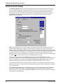
Applications ..................................................................................................................................................... 71
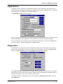
Diagnostics ...................................................................................................................................................... 71
iii
Chapter 5 - Client Setup ............................................................................... 73
Introduction ..................................................................................................................................................... 74
Before you Begin ............................................................................................................................................. 74
Configuring in Windows 98/95 ......................................................................................................................... 75
Installing TCP/IP (Win98/95) .......................................................................................................................... 82
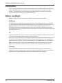
Configuring in Windows NT ............................................................................................................................. 83
Installing TCP/IP (WinNT) .............................................................................................................................. 89
Chapter 6 - RAS Dial-Out Redirector .......................................................... 91
Introduction ..................................................................................................................................................... 92
Installing and Configuring the WINMCSI Modem-Sharing Software ............................................................... 92
Running the WINMCSI Workstation Software ................................................................................................. 96
Chapter 7 - Remote Configuration and Management ................................ 99
Introduction ................................................................................................................................................... 100
Remote Configuration ................................................................................................................................... 100
Modem-Based ........................................................................................................................................ 100
LAN-Based ............................................................................................................................................. 102
Remote Management .................................................................................................................................... 104
Telnet ...................................................................................................................................................... 104
Web Browser Management .................................................................................................................... 106
Chapter 8 - Service, Warranty and Tech Support .................................... 109
Introduction ................................................................................................................................................... 110
Limited Warranty ........................................................................................................................................... 110
On-line Warranty Registration ................................................................................................................. 110
Tech Support ................................................................................................................................................. 110
Recording RASFinder Information .......................................................................................................... 110
Service .................................................................................................................................................... 111
About the Internet .......................................................................................................................................... 111
Ordering Accessories .................................................................................................................................... 112
Appendixes ................................................................................................. 113
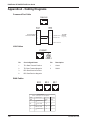
Appendix A - Cabling Diagrams ..................................................................................................................... 114
Appendix B - Script Language ....................................................................................................................... 115
Appendix C - Regulatory Information ............................................................................................................ 118
Class B Statement .................................................................................................................................. 118
Fax Branding Statement ......................................................................................................................... 118
FCC Part 68 Telecom .............................................................................................................................. 119
Ringer Equivalence Number ................................................................................................................... 120
EMC, Safety and Terminal Directive Compliance ................................................................................... 120
Appendix D - AT Commands ......................................................................................................................... 121
Appendix E - TCP/IP ..................................................................................................................................... 162
TCP/IP .................................................................................................................................................... 162
Internet Protocol (IP) ............................................................................................................................... 164
Appendix F - Modem AT Commands ............................................................................................................. 165
Glossary of Terms ...................................................................................... 183
Index ............................................................................................................ 197
iv
Remote Access Device
Chapter 1 - Introduction and Description
RASFinder RF300E/RF310E User Guide
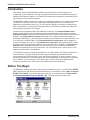
Introduction
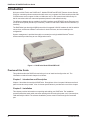
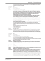
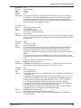
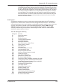
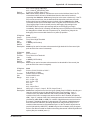
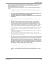
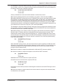
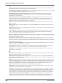
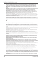
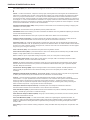
Welcome to Multi-Tech's new RASFinder™, Models RF300E and RF310E, Remote Access Servers
(RAS) for connecting telecommuters and mobile users to a corporate LAN. Both models provide 56K
or ISDN remote server support for dial-out LAN users on IP or IPX networks and LAN security for
dial-in connections with user name and password protection and callback security.
The difference between the two models is the ISDN interface, model RF300E has the European and
rest of the world (ROW) interface (S/T-Interface), model RF310E has the North America interface (UInterface).
The RASFinder has three hybrid ISDN ports with six integrated V.90/56K modems for dial-in and dialout services, an Ethernet 10BaseT connection for local LAN users, and a command port for
configuration.
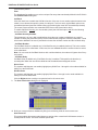
System management is provided through the command port using bundled Windows® based
software which provides easy-to-use configuration menus.
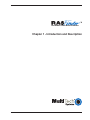
Figure 1-1. RASFinder Model RF300E/RF310E
Preview of this Guide
This guide describes the RASFinder and tells you how to install and configure the unit. The
information contained in each chapter is as follows:
Chapter 1 - Introduction and Description
Chapter 1 describes the new hybrid RASFinder. Descriptions of the front panel indicators and back
panel connectors are provided. A list of relevant specifications is provided at the end of the chapter.
Chapter 2 - Installation
This chapter provides information on unpacking and cabling your RASFinder. The installation
procedure describes each cable connection starting with connecting the power cord, Command port,
LAN and finally the WAN. The software installation process must be done through the Command
port.
6
RF300E/RF310E
Chapter 1 - Introduction and Description
Chapter 3 - Software Loading and Configuration
Chapter 3 details the software loading and initial configuration. Initially, the RASFinder software
configures the unit for a Remote Access Server (RAS) configuration. If you want to configure the
RASFinder for a Lan-to-Lan configuration, you will have to change the Remote Port Setup to a Client
or LAN setting. The RASFinder can also be configured to operate in either a RAS application using a
Radius server for security services or a RAS application using the proprietary Remote User Data
Base Utility for remote user authentication.
Chapter 4 - RASFinder Software
Chapter 4 describes the RASFinder software designed for the Windows® environment. The software
contains a number of utilities that allow for downloading updated firmware, creating a proprietary
Remote User Data Base, and a terminal emulation utility for configuring the internal modems. Three
typical applications are provided to show you how the RASFinder can be configured and some insight
into the application.
Chapter 5 - Client Setup
This chapter provides information for enabling and configuring multiple Windows 98/95 or NT® PC
users for Internet access via the RASFinder.
Chapter 6 - RAS Dial-Out Redirector
Chapter 6 describes how Multi-Tech’s Remote Access Server for Microsoft network users enables
them to dial out and fax out through the RASFinder. It provides information on installing and
configuring the WINMCSI modem-sharing software.
Chapter 7 - Remote Configuration and Management
This chapter provides procedures for changing the configuration of a remote RASFinder located
elsewhere on a LAN or at the other end of a modem connection. This chapter also describes typical
Telnet client and Web-browser management of the RASFinder.
Chapter 8 - Service, Warranty and Tech Support
This chapter provides statements concerning the product warranty, provides space for recording
information about your RASFinder prior to calling Multi-Tech’s Technical Support, and includes
instructions for contacting Technical Support and returning your RASFinder to the factory if it requires
service. Also included is information on how to obtain product support through the Internet.
RF300E/RF310E
7
RASFinder RF300E/RF310E User Guide
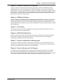
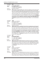
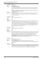
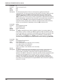
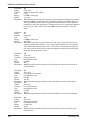
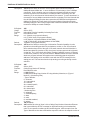
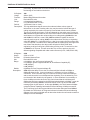
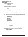
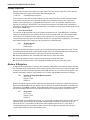
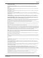
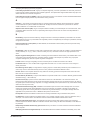
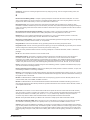
Front Panel
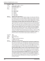
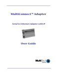
The front panel has four groups of LEDs that provide the status of the LAN connection and link
activity. Two other LEDs indicate the general status of the RASFinder. The Ethernet LEDs display the
activity of the LAN in whether the RASFinder is connected to the LAN, transmitting or receiving
packets, and if a collision is in progress. The Link LEDs display the status of the three links that can
be connected to the RASFinder and show whether a link is ready to transmit or receive serial data.
The last two LEDs indicate whether the self test passed or failed and if the power ON/OFF switch on
the back of the RASFinder is set to ON.
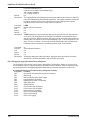
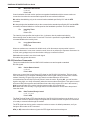
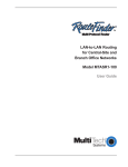
Figure 1-2. Front Panel
LAN
LD
TBD.
TX
Transmit Data indicator blinks when packets are being transmitted to the local area network.
LK
Link indicator lights indicating that the RASFinder is connected to the local area network.
RX
Receive Data indicator blinks when packets are being received from the local area network.
BRI x
RD
Receive Data indicator blinks when the link is receiving data.
TD
Transmit Data indicator blinks when the link is transmitting data.
CD
Carrier Detect indicator lights when the link detects a carrier signal.
TR
Terminal Ready indicator blinks when the link is ready to transfer data.
BOOT The BOOT indicator lights for 3 minutes when power is applied to the RASFinder; if it
remains on for over 3 minutes, it indicates that a boot failure has occurred.
PWR
8
The power indicator lights when the On/Off switch is in the up (1) position.
RF300E/RF310E
Chapter 1 - Introduction and Description
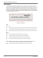
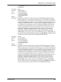
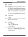
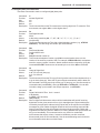
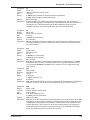
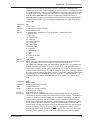
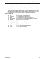
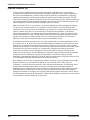
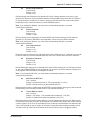
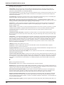
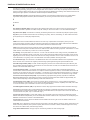
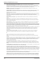
Back Panel
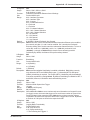
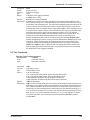
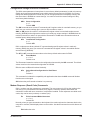
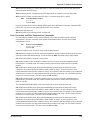
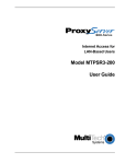
All the cable connections for the RASFinder are made at the back panel. Three groups of cables (all
using RJ-45 jacks) are used with the RASFinder: the Command Port, BRI 1 (2 and 3), and the
Ethernet. The cable connections are shown in Figure 1-3 then defined below.
1
0
10BASET
COMMAND
POWER
BRI 3
BRI 2
BRI 1
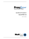
Figure 1-3. Back Panel
BRI 1 (2 and 3)
Each of these three RJ-45 jacks is used to connect the RASFinder to a WAN.
Ethernet 10BASET
The Ethernet 10BASET connector is used to connect the RASFinder to a LAN over unshielded
twisted pair (UTP) cable. This connector is an RJ-45 jack.
COMMAND
The COMMAND connector is used to configure the RASFinder using a PC with a serial port and
running Windows® software. The Command connector is an RJ-45 jack, and a short adapter cable is
provided to convert to a standard serial port DB9 female connector.
Power Connector
The Power connector is used to connect the external power supply to the RASFinder. The Power
connector is a 6-pin circular DIN connector. A separate power cord is connected between the power
supply and a live AC grounded outlet.
RF300E/RF310E
9
RASFinder RF300E/RF310E User Guide
Specifications
The RASFinder conforms to the following specifications:
•
Routing Protocols - IP and IPX, and bridging for all others
•
Ethernet LAN Interface - 10Base-T (twisted pair)
•
Three ISDN BRI ports consisting of six V.90/56K modems or six ISDN modems
•
Command port - 19.2 Kbps Asynchronous
•
10BaseT Ehternet port
•
Two 70-nanosecond 4 MB SIMMs (8 MB, total)
(RAM is expandable to a maximum of 32 MB)
Caution: SIMM speed and size cannot be mixed.
•
1 MB of Flash memory (on two PROMs)
Ethernet Port
•
One Ethernet Interface - 10Base-T (twisted pair) RJ-45 connector
Command Port
•
Single 56.6K bps asynchronous Command Port using a short RJ-45-to-DB25 cable with a
DB25 female connector
WAN Links
•
Six internal V.90/56K modems or six ISDN modems
Electrical/Physical
•
Voltage - 115 VAC (Standard), 240 VAC (Optional)
•
Frequency - 47 to 63 Hz
•
Power Consumption - 10 Watts
•
Dimensions - 2.3" high x 8.4" wide x 6.1" deep
5.8 cm high x 21.3 cm wide x 15.5 cm deep
•
Weight - 1.6 pounds (790g)
Requirement
•
*
10
PC with Windows 9X/NT/2000, and one available serial COM port to connect to the
Command port of the RASFinder
Though this modem is capable of 56K bps download performance, line impairments, public
telephone infrastructure and other external technological factors currently prevent maximum 56
Kbps connections.
RF300E/RF310E
Remote Access Device
Chapter 2 - Installation
RASFinder RF300E/RF310E User Guide
Safety Warning Telecom
1. Never install phone wiring during a lightning storm.
2. Never install phone jacks in wet locations unless the jacks are specifically designed for wet
locations.
3. This product is to be used with UL and cUL listed computers.
4. Never touch uninsulated phone wires or terminals unless the phone line has been disconnected
at the network interface.
5. Use caution when installing or modifying phone lines.
6. Avoid using a phone (other than a cordless type) during an electrical storm. There may be a
remote risk of electrical shock from lightning.
7. Do not use the phone to report a gas leak in the vicinity of the leak.
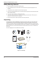
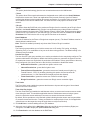
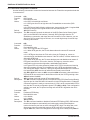
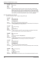
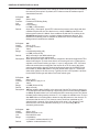
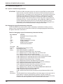
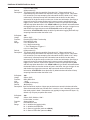
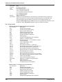
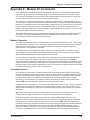
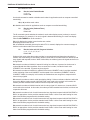
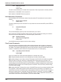
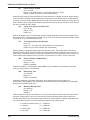
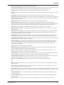
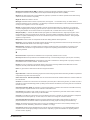
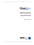
Unpacking
The shipping box contains the RASFinder, external power supply, cables, your Quick Start Guide,
and the RASFinder CD with the RASFinder Software and User Guide in Adobe® Acrobat format.
Inspect the contents for signs of any shipping damage. If damage is observed, do not power up the
unit; contact Multi-Tech’s Technical Support for advice (refer to Chapter 8). If no damage is observed,
place the RASFinder in its final location and perform the procedures in the section on Cabling Your
RASFinder.
www.multitech.com
www.multitech.com
Save the shipping box in case reshipment is necessary.
Remote Access Device
Tucows
Remote Access Device
Remote Access Device
RD TD
MADE
CL
IN U.S
LK
.A
RD
TD
CD
NS
DS
RD
TD
CD
V35
MADE IN
U.S.A
Figure 2-1. Unpacking
12
RF300E/RF310E
Chapter 2 - Installation
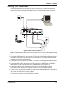
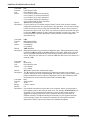
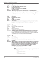
Cabling Your RASFinder
Cabling your RASFinder involves making the proper WAN, Ethernet, Command Port, and Power
connections. Figure 2-2 shows the back panel connectors and the associated cable connections.
The procedures for connecting the cables to your RASFinder are provided below.
Ethernet Connection
1
Power Connection
0
10BASET
COMMAND
POWER
BRI 3
BRI 2
BRI 1
WAN Connections
Figure 2-2. Back Panel Connections
Note: If additional RAM is needed, perform the procedure in the next section, Adding Additional RAM.
The following steps detail the procedures for connecting the cables to your RASFinder.
1
Connect the RASFinder to a PC using the short RJ-45 to DB9 (female) cable provided with the unit.
Plug the RJ-45 end of the Command cable into the Command Port of the RASFinder and the other
end into the PC's serial port. See Figure 2-2.
2
Connect an RJ-45 (UTP) cable to the 10 BASE-T connector on the back of the RASFinder. Connect
the other end of the cable to your LAN.
3
Connect one end of a UTP cable to each of the BRI Connectors on the RASFinder (labeled BRI 1,
BRI 2, and BRI 3) and connect the other end to a WAN jack (as shown in Figure 2-2).
4
Connect one end of the power supply to a live AC outlet, then connect the other end to the
RASFinder as shown in Figure 2-2. The power connector is a 6-pin circular DIN connector.
5
Turn on power to the RASFinder by setting the ON/OFF switch on the back panel to the ON position.
At this time your RASFinder is completely cabled.
Proceed to the next section to install the RASFinder software.
RF300E/RF310E
13
RASFinder RF300E/RF310E User Guide
14
RF300E/RF310E
Remote Access Device
Chapter 3 - Software Loading and Configuration
RASFinder RF300E/RF310E User Guide
Introduction
This chapter covers procedures for loading the RASFinder software from a Windows PC (Win98/95
or WinNT) and configuring your RASFinder. Configuration includes setting up the LAN and WAN port
IP addresses, setting up the ISDN configuration default parameters, then downloading the default
setup to the target ISDN RASFinder.
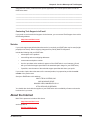
Before You Start Loading your Software
Consider the following choices before you configure your RASFinder and record your selections on
the following pages; then refer to them while loading your software.
Network Configuration
ü Network Switch Type_________________________________________
Select the network switch type your ISDN service provider uses at its local central office. You can set
the RASFinder to NET3 (EuroISDN), or 1TR6 (German), AT&T 5ESS, DMS-100, or NI-1. If you do
not know the switch type, you can get the information from your ISDN service provider.
ü Data TEI_____________________________________________________
The Data TEI (Terminal Endpoint Identifier) is assigned to the data channel. You can select “Auto TEI,”
a fixed TEI, number (from 0 to 63), or “Disabled.” A TEI is a number used by the central office switch to
uniquely identify each device that is connected to the network. When it uses dynamic TEI assignments
(Auto TEI), the central office switch assigns a TEI each time the RASFinder connects to the network.
However, the ISDN service provider may assign a fixed TEI at subscription time, in which case you
must configure the RASFinder with the fixed TEI number. You can also disable the channel, which may
be useful when multiple RASFinders are attached to a network terminator bus.
ü Voice TEI___________________________________________________
The Voice TEI is the TEI assigned to the voice channel. You have the same choices as for the Voice
TEI: “Auto TEI,” a fixed TEI number (from 0 to 63), or “Disabled.”
ü Data SPID__________________________________________________
The RASFinder must be configured with the Service Profile Identifier (SPID). The data SPID is
assigned by the local phone company and is for the specific Basic Rate Interface (BRI) line to which
the RASFinder will be attached. The data SPID string can have up to 20 characters. The data SPID
is not used if the switch type is set to NET3.
Note: For DMS-100 switches, any ASCII character except the underline (_) character is valid. For
NI-1 and AT&T switches, only the digits 0-9 are valid.
ü Voice SPID__________________________________________________
The voice SPID is assigned by the local phone company and is for the specific BRI line to which the
RASFinder will be attached. The voice SPID string can have up to 20 characters. The data SPID is
not used if the switch type is set to NET3.
Note: For DMS-100 switches, any ASCII character except the underline (_) character is valid. For
NI-1 and AT&T switches, only the digits 0-9 are valid.
ü Data Directory Number________________________________________
The data Directory Number (DN) is a telephone number that is assigned to the RASFinder at
subscription time by the ISDN service provider. The DN is a string of up to 24 characters; valid
characters are 0-9, the * character, and the # character.
ü Voice Directory Number_______________________________________
The voice Directory Number (DN) is a telephone number that is assigned to the RASFinder at
subscription time by the ISDN service provider. The DN is a string of up to 24 characters; valid
characters are 0-9, the * character, and the # character.
16
RF300E/RF310E
Chapter 3 - Software Loading and Configuration
Call Control Parameters
ü Persistent DTR Dialing_______________________________________
A high DTR (Data Terminal Ready) signal on the Command port indicates that your computer or
terminal is ready to communicate with your RASFinder. DTR normally goes high when a
communication program starts or is ready to dial. Persistent DTR dialing enables the RASFinder to
automatically redial the number stored in memory location 0 whenever DTR is high and the serial port
does not have an active call. You may enable or disable this feature.
ü Calling Line Identification_____________________________________
Identifies whether the two endpoints of a connection are enabled or disabled. Since RING
messages only appear for ISDN data calls, the CLI feature does not define a means of conveying
Calling Party information to the terminal for ISDN voice calls. The CLI information is only included
with the first RING message for a given incoming call and appears as follows:
RING
FM: 5552000 TO: 5551000
If the Calling Party Number information is not included in the incoming SETUP message, the RING
message appears as follows:
RING
TO: 5551000
If the Called Party Number information is not included in the incoming SETUP message, the RING
message will appear as follows:
RING
FM: 5552000
If neither the Called Party Number, nor the Calling Party Number is included in the incoming SETUP
message, the RING message will contain no additional information.
ü Auto Protocol Detection Identifies that automatic protocol detection is enabled or disabled for an ISDN data call. The default
setting is 1, which enables the Auto-Protocol Detection function.
ü Auto Answer Data Calls ____ __________ Rings to Answer__________
Select Auto Answer if you want your RASFinder to automatically answer all incoming data calls (this
option does not affect the analog port). The Rings to Answer number, in the range of 1 to 255,
selects the number of rings the RASFinder waits before answering an incoming call. The default is
one ring.
Data Control
ü Data Protocol _______________________________________________
The data protocol, also known as the B-channel protocol and the rate adaption protocol, is the
“language” that is spoken over each 64 Kbps channel between two ISDN devices. The devices on
both ends of the ISDN link must use identical data protocols.
ü Dialing Method _______________________________________________
Select either the “Enbloc” or the “Overlap” dialing method for use when establishing a data call. Your
ISDN service provider determines the dialing method. The en bloc method is used for most ISDN
dialing; however, you can select the overlap method if you are working with a private network.
RF300E/RF310E
17
RASFinder RF300E/RF310E User Guide
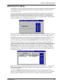
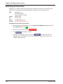
Installing Your RASFinder Software
The default application of the RASFinder is as a Remote Access Server equipped with a database of
remote users for dialing into their corporate LAN. The RASFinder can also be configured to serve as
a LAN-to-LAN router; however, this requires additional setup through the main menu after completion
of the basic software installation process.
Note: If you are configuring your RASFinder and loading software for North America (US
Parameters), be sure you have Model RF310E (U-Interface).
If you are configuring your RASFinder and loading software for European Parameters or Rest of
World (ROW), be sure you have Model RF300E (S/T-Interface).
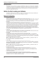
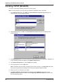
1. Insert the RASFinder CD-ROM into the CD-ROM drive on your local PC. The CD-ROM should start
automatically; however, it may take 10 to 20 seconds for the Multi-Tech RASFinder Autorun screen to
appear.
2. If the Multi-Tech Installation CD Screen does not appear automatically, click My Computer, then
right-click the CD-ROM drive icon and click Autorun.
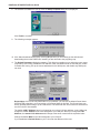
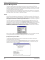
3. When the Multi-Tech Installation CD Screen appears, click the Install Software icon.
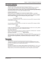
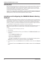
4. The Welcome screen is displayed.
Press Enter or click Next> to continue.
18
RF300E/RF310E
Chapter 3 - Software Loading and Configuration
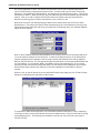
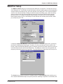
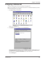
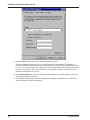
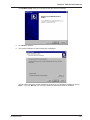
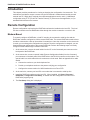
5
The Choose Destination Location dialog box is displayed. Follow the onscreen instructions to
install your RASFinder software.
You can either choose a different Destination Location for your RASFinder software by clicking
Browse, or select the default destination by clicking Next> or pressing Enter. It is recommended that
you accept to the default location, c:\RF300E.100.
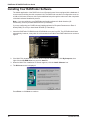
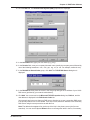
6
When the Select Program Folder dialog box enables you to name the program group for the
RASFinder icons. You can either select the default name, RF300E 1.00 or name it anything you like.
Press Enter or click Next> to continue.
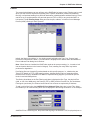
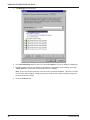
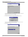
7
The next dialog box enables you to designate the COM port of the PC that is connected to the
RASFinder. On the Select Port field, click the down arrow and choose the COM port of your PC
(COM1 -- COM4) that is connected to the RASFinder.
Click OK to continue.
RF300E/RF310E
19
RASFinder RF300E/RF310E User Guide
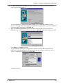
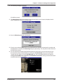
8
The software is loaded onto your pc, then the Setup Complete dialog box is displayed.
Click Finish to continue.
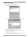
9
The following message appears:
10 Click Yes to download wizard setup. Clicking No prevents you from setting up the defaults and
downloading them to the RASFinder; instead, you are returned to the program group.
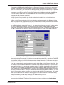
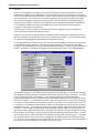
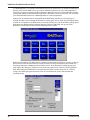
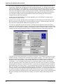
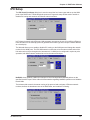
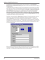
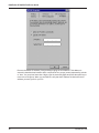
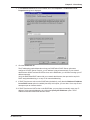
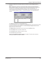
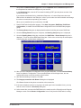
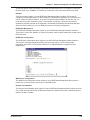
11 The Default Parameters dialog box appears. This dialog box enables you to assign the router name
(required for IPX routing), establish the IP address, mask, and default route for the LAN port, enable
or disable IPX routing, set up the remote addresses for the WAN ports, and disable any WAN ports
not used.
Router Name: If this is the only RASFinder on your network, you can use the default Router Name
(MTROUTER); otherwise, you must assign a new Router Name in this field. The Router Name can
be any printable ASCII string of up to 8 characters. The RASFinder will use this name to advertise its
service in the IPX internetwork.
The default LAN IP Address has to be changed to your unique LAN port address. In the LAN group,
change the default Address to the value assigned to your LAN port. When you change the LAN
Address, the remote WAN addresses also change to the same network and in sequential order.
Change the default Mask to the value assigned to your LAN port.
If you established a Default Route on your LAN, enter the address of the route.
20
RF300E/RF310E
Chapter 3 - Software Loading and Configuration
12 The following message is displayed.
Click OK to proceed.
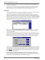
13 The Writing Setup dialog box (with the current date and the file size in bytes) is displayed as the
setup configuration is written to the RASFinder.
14 Next, the Rebooting dialog box is displayed.
15 Check to ensure that the BOOT LED on the RASFinder goes Off after the download is complete and
the RASFinder is rebooted (the Rebooting dialog box goes away). This may take several minutes as
the RASFinder reboots.
16 You are returned to the Multi-Tech RASFinder Autorun screen where you can now install (on your
PC’s hard drive) either Acrobat Reader (by clicking the Acrobat Reader icon) or the User Guide.
To install the User Guide, click the Install Manuals icon, then click OK and the files will install at
C:\Program Files\Multi-Tech Systems, Inc.\RF300E\Documentation unless you browse and select
an alternate directory for installation.
RF300E/RF310E
21
RASFinder RF300E/RF310E User Guide
17 If you need to enter ISDN parameters, proceed to step 18.
If you want at this time to set up your RASFinder as a RAS with the Proprietary user database,
proceed to Setting Up Your Remote User Database section in this Quick Start Guide.
If you want at this time to set your RASFinder so that a Radius server provides your user database,
proceed to Setting Up RADIUS.
If you want at this time to set up your RASFinder for LAN-to-LAN routing, proceed to the Final
Routing Setup section.
18 If you need to enter specific ISDN parameters (SPIDs) and DNs for North America, or data and voice
ISDNs and subaddresses for European Parameters, click Start | Programs | RF300E 1.00 |
RASFinder Configuration, or double-click the RASFinder Configuration icon in the RF300E 1.00
icon group window when it is displayed on your desktop. The main menu (Router Setup) is
displayed.
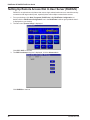
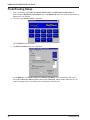
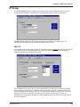
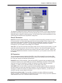
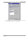
19 From the Main menu, click the WAN button. The WAN Port Setup screen is displayed.
22
RF300E/RF310E
Chapter 3 - Software Loading and Configuration
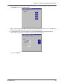
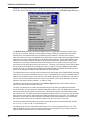
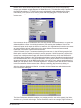
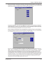
20 Click the Advanced tab.
21 Select (highlight) the WAN port you want to configure, then click Edit. The ISDN Parameter
Configuration dialog box is displayed with the Config name window displaying the WAN port you just
selected.
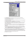
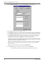
22 Click the down arrow for Net Switch Type and highlight the switch type used by your Telco. If
necessary, refer to your Network Switch Type entry in Before You Start Loading your Software. The
default is NET3 (for EuroISDN). Available selections for the USA are: AT&T 5ESS, DMS-100, and NI1. VN4 is for France, ITR6 is for Germany, and INS64 is for ISDN BRI (Japanese).
23 Click the Data TEI field on the General tab. Refer to your Data TEI entry in the Network
Configuration section in Before You Start Loading Your Software. If the Data TEI is different, click the
drop-down list arrow and click the selection that corresponds to the Data TEI (i.e., Disabled, Auto
TEI, or zero to 63) supplied by your Internet service.
24 Click the Voice TEI field on the General tab. Refer to your Voice TEI entry in the Network
Configuration section in Before You Start Loading Your Software. If the Voice TEI is different, click
the drop-down list arrow and click the selection that corresponds to the Voice TEI (i.e., Disabled, Auto
TEI, or zero to 63) supplied by your Internet service.
25 Depending on the switch type chosen above, either the US Parameters group or the Europe
Parameters group will be activated.
If the US Parameters group is activated you may have to enter the SPID and Directory number(s)
associated with the WAN port in the Config name window.
A SPID (Service Profile IDentifier) is a number that is supplied to you by your local phone company
which encompasses the phone number.
A Data or Voice Directory Number (DN) is the phone number assigned to that B-Channel for the BRI
line provisioned by your phone company. If a DN is assigned, then only the device associated with
that WAN port will respond to the call.
RF300E/RF310E
23
RASFinder RF300E/RF310E User Guide
CAUTION: WANs 1 and 2 correspond to BRI 1. B-Channel 1 of BRI 1 corresponds to WAN 1, and BChannel 2 of BRI 1 corresponds to WAN 2. The BRI line from the Telco has to be connected to the
corresponding port on the RASFinder (e.g., BRI Line 1 has to be connected to BRI 1 port on the back
of the RASFinder. The SPID and Directory Number (if used) for the BRI line assigned by the Telco
have to be entered on the ISDN Parameter Configuration dialog box for the corresponding WAN
number. WANs 1 and 2 are associated with BRI Line 1 and BRI 1 port on the back of the RASFinder.
Each of these entries has to correspond to the way the Telco provisioned the line, or else calls will not
go through.
If the chosen switch type activates the Europe Parameters group, you may have to enter Data/Voice
ISDN and Sub Addresses associated with the WAN port displayed in the Config name window.
Enter the Data/Voice ISDN associated with the WAN port displayed in the Config name window.
The Data and Voice ISDN numbers can be up to 20 characters in length. The Data/Voice ISDNs are
assigned by your local phone company for the specific BRI line attached to the RASFinder. The BRI
line has to correspond to the BRI port on the back of the RASFinder and the B channel of that line
has to correspond to the WAN Port number; e.g., BRI Line 1 B-Channel 1 corresponds to WAN 1 and
BRI Line 1 B-Channel 2 corresponds to WAN 2.
26 When you have finished entering the Parameter information for your WAN port, click OK and you are
returned to the WAN Port Setup dialog box; the ISDN TA Control group and the WAN number you
just configured will be highlighted.
27 Highlight the next WAN port you want to configure, then click Edit. Repeat steps 22 and 26 for each
WAN port you need to configure.
28 When all the necessary WAN ports are configured, click OK twice to return to the Main menu.
29 At this time your RASFinder is operational.
If you want to assemble your Remote User Database, proceed to the next section.
If you want to setup your Radius, proceed to Setting Up RADIUS section.
If you are setting up your RASFinder for routing, proceed to the Final Routing Setup section.
24
RF300E/RF310E
Chapter 3 - Software Loading and Configuration
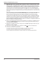
Setting Up Your Remote User Database
The proprietary Remote User Data Base supports remote dial-in users for user name, password, and
port availability. Each dial-in user needs an entry in this database. You can add remote users, remove
users, or edit information in the database.
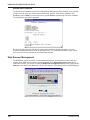
1
From your desktop, click Start | Programs | RF300E 1.00 | Remote User Data Base, or double-click
the Remote User Data Base icon in the RF300E 1.00 icon group window (below).
2
An Accounting Info - Read screen appears briefly, then the Users List dialog box is displayed.
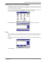
Filters
Part of the database is the type of filtering that is applied to each user (e.g., filtering on an IP address
or filtering on a specific protocol). These filtering conditions are established by clicking the Filters
button.
3
Click Filters to establish the filtering parameters for the remote user entry. the Filters List dialog box
is displayed.
Click the Add button.
RF300E/RF310E
25
RASFinder RF300E/RF310E User Guide
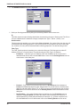
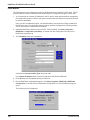
4
The Add/Edit Filters dialog box is displayed.
5
Build your filtering parameters by filling in the following fields for each remote user.
ID
This field requires a unique filtering identification characterizing the type of filtering used. The ID can
be up to 9 alphanumeric characters in length; examples are: Type 1, Server 1, Setup 1, etc.
Default Action
This drop-down list enables you to select either filter or forward. If you select filter, then the entry will
be transmitted with filtering properties. If you select forward, you will still have to select a filter type,
etc.; however, the entry will be transmitted without filtering properties. The default setting is filter.
Filter Type
The Filter Type drop-down list enables you to select the filter type. The filter types are either IP
Address, Protocol, or Domain Name. The default setting for Filter Type is IP Address.
26
•
IP Address – If the filter type is IP Address, enter the IP Address of the remote user in
dotted-decimal format, then click the Add button to move it to the Existing Entries text box
at the bottom of this dialog box.
•
Protocol – If you select Protocol as the filter type, the IP Address text box changes to
Protocol and Port drop-down list fields. Select either TCP or UDP from the Protocol dropdown list and select either Telnet, FTP, or SFTP from the Port drop-down list, then click the
Add button to move these selections to the Existing Entries text box at the bottom of this
dialog box.
•
Domain Name – If you select Domain Name as the filter type, the IP Address text box
changes to a Domain Name field. Enter the domain name consisting of a sequence of
names separated by periods (dots) followed by an extension; e.g., “pictures.computers.com.”
Click the Add button to move the domain name to the Existing Entries text box at the
RF300E/RF310E
Chapter 3 - Software Loading and Configuration
bottom of this dialog box. The domain name can be up to 39 alphanumeric characters
including periods.
Click OK to add the current entry to the Filters List dialog box, then repeat step 5 until all necessary
Filter IDs are defined.
6
When done, click OK again to return to the Users List dialog box, then click Download to save the
filter entries to the RASFinder.
While still at the Users List dialog box, click Add.
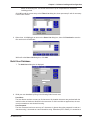
Build User Database
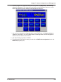
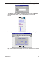
7
8
The Add Users dialog box is displayed.
Build your user database by filling in the following fields for each user.
User Name
The User Name can have as many as 39 characters. All printable characters are permitted with the
restriction that no blanks are allowed in the user name. In dial-in and dial-out applications, the user
name is treated as a case insensitive string.
User Password
The User Password can have as many as 7 characters. In places where the password is used as a
character string, it is treated as a case insensitive string. Elsewhere (PPPs CHAP), it is treated as a
RF300E/RF310E
27
RASFinder RF300E/RF310E User Guide
case sensitive pattern.
Filter
The drop-down list enables you to select a unique filter entry that was already defined in the ID field in
the Add/Edit Filters dialog box.
Call Back
Click this check box to enable the Call Back function. If the user is at a number where he wants to be
called, he can choose the specific number for call back. For this to work, the Call Back option must
be enabled (activated) and the Call Back Security Enabled option must NOT be enabled (activated).
The remote user would then use a standard PPP client or ASCII terminal to dial-in.
To enable Call Back Security, you must enable (check) the Call Back option and fill in the following
three boxes/fields.
• Call Back Security Enabled
This parameter is of use in dial-in applications where the user is always called back at a specific
number. Enabling this parameter (Alt-S) lets the administrator assign the call back parameters. Leave
this function disabled if the user is permitted to choose the call back number and the call back delay.
• Call Back Number
The Call Back Number is editable only if Call Back Security is enabled (checked). This is the number
where the user will be called back. In this case, the user cannot choose the number where he wants
to be called back.
Note: You can enter the Call Back Number with or without dashes, the modem will ignore them if they
are present.
• Call Back Delay
Call Back Delay is editable only if Call Back Security is enabled. This specifies the duration (in
seconds) after which the user will be called back at the administrator-assigned number.
Dial In Ports
The systems administrator can enable (highlight) any WAN Ports 1 through 6 to be made available for
dialing in to the RASFinder.
Dial Out Ports
The systems administrator can enable (highlight) WAN Ports 1 through 6 to be made available for
dialing out from the RASFinder.
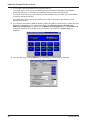
Click the Rights button to assign user permissions for the remote user.
9
The User Permissions dialog box is displayed.
10 Build your user permissions database by filling in the following fields for each remote user.
Auto Protocols
This group enables the systems administrator to assign either unrestricted LAN/Intranet access or
limited protocol access. The three available options are:
28
RF300E/RF310E
Chapter 3 - Software Loading and Configuration
• None
This option (the default setting) gives the user unrestricted access to the LAN/Intranet.
• Telnet
This option allows Telnet sessions between the designated server (defined in the Host IP Address
field) and the remote user. Telnet is an applications-level protocol commonly found in IP-based
networks that allows terminal emulation at a remote workstation. If you select Telnet, you must enter
an IP address in the Host IP Address field. This limits the user to only specific functions on the
network.
• RLogin
This option allows the RASFinder to be used as an RLogin client for connecting to an RLogin Server
(defined in the Host IP Address field). RLogin is an application protocol that provides a terminal
interface between Unix hosts using TCP/IP network protocol. Unlike Telnet, RLogin assumes that the
remote host is a Unix machine. If you select RLogin, you must also enter an IP address in the Host
IP Address field. This limits the user to only specific functions on the network.
Host IP Address
Enter the IP Address for the Telnet or RLogin host computer (server). The Host IP Address must be in
dotted-decimal notation format.
Note: This field is enabled (activated) only when either Telnet or RLogin is enabled.
Protocols
The Protocols group enables you to limit the remote user to IP routing, IPX routing, or bridging
(Spanning Tree); or, a combination of any two or all three routing protocols. The default setting is for
all three protocols enabled.
User Service Types
The User Service Types group enables you to set the permissions for the entry being configured. The
systems administrator can enable or disable the following options to customize the types of services
for a particular remote user. By default, all permissions are enabled. To deny permissions to the entry
being configured, click (check) the box to the left of the permission to disable the feature.
•
Outbound Permissions - grants dial-out rights to remote user.
•
Inbound Permissions - grants dial-in rights to user.
•
Framed Protocol Permissions - grants the remote user framed protocol rights (e.g.,
Framed Protocol – PPP). By enabling (checking) this option, the user becomes an
unrestricted user (i.e., both framed and unframed protocols are allowed).
•
Telnet Permissions - grants the remote user Telnet file transfer rights.
•
RLogin Permissions - grants the remote user RLogin server connection rights.
Time Limits
The Time Limits group enables the systems administrator to impose various types of time-related
restrictions on the user account.
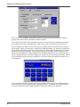
Time of the Day Logins
The User Permission grid enables the administrator to deny a remote user Internet access at certain
times during the week. This would be applicable when the administrator wants to bring a system
down for a particular reason and doesn’t want users to access the Internet at that time.
By default, all time periods are color-filled with yellow indicating that the remote user has permission
to access the Internet all the time. To deny permission for certain periods of time, click all applicable
yellow boxes over the target time range to toggle them to red (Access Denied).
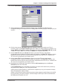
11 Click Add User to continue adding users to your database.
12 After each user is defined in the Add Users dialog box and all the user permissions (Rights) are
configured, click OK to display the updated Users List dialog box.
13 Click Download to write the database to the RASFinder.
RF300E/RF310E
29
RASFinder RF300E/RF310E User Guide
Setting Up Remote Access Dial In User Server (RADIUS)
RADIUS is an optional security feature that uses a single authentication server to centralize security
on networks with large modem pools, especially those with multiple communication servers.
1. From your desktop, click Start | Programs | RASFinder 3.10 | RASFinder Configuration, or
double-click the RASFinder Configuration icon in the RASFinder 3.10 icon group window when it
is displayed on your desktop.
2. The main menu (Router Setup) is displayed.
Click PPP / SLIP to continue.
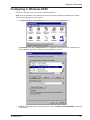
3. The PPP Port Setup dialog box is displayed; click the Advanced tab.
Click RADIUS to continue.
30
RF300E/RF310E
Chapter 3 - Software Loading and Configuration
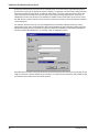
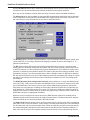
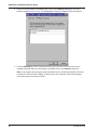
4. The Radius Setup dialog box is displayed.
5. Click RADIUS Enable to enable Radius security services for all ports on this RASFinder.
6. Click Accounting Enable if you want Radius to track accounting information such as login and
logout times, bytes sent and received, etc.
7. Leave Allow Call if Security Server Down unchecked (disabled) to prevent users from logging in if
the security servers are down.
8. Click Assign Remote Address Using RADIUS to enable the Radius Server to automatically assign
the IP Address of the WAN port on the RASFinder that the user will dial into.
9. Obtain the Shared Secret from the Radius network administrator. The Shared Secret must be the
same secret that is used on the Radius server whose address is being supplied for the Radius
primary server address entry.
10. Obtain the Radius server address from the Radius network administrator that will provide the security
to the RASFinder. The Radius server address is to be enterred in the RADIUS Primary Server
Address field.
11. If additional servers are being used as backup servers, obtain their address(es) from the Radius
network administrator and enter them in Backup Servers group. The first backup server address is
enterred in the Backup Server Address 1 field. Any additional backup server addresses are to be
enterred in the Backup Server Address 2 and Backup Server Address 3 fields.
12. A set of default attribute values will be displayed in the Attribute Values group. These default values
are used with the Multi-Tech Radius Server. You do not have to change these values if your
RASFinder is communicating with Multi-Tech’s Radius Server. If you are using another vendor’s
Radius Server to communicate with your RASFinder, you will have to communicate with your Radius
Server network administrator to see how he/she has set up these attribute values and then change
the default values to the values being used by that Radius server.
13. Click OK when you are finished.
RF300E/RF310E
31
RASFinder RF300E/RF310E User Guide
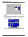
Final Routing Setup
1. From your desktop, click Start | Programs | RASFinder 3.10 | RASFinder Configuration, or
double-click the RASFinder Configuration icon in the RASFinder 3.10 icon group window when it is
displayed on your desktop.
2. The main menu (Router Setup) is displayed.
Click PPP/SLIP button to continue.
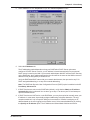
3. The PPP Port Setup dialog box is displayed.
On the WAN tab, click Client or LAN in the Remote Port Setup group in the bottom right corner;
this enables Client or LAN and disables the default, Client only. Select another WAN port you are
using and repeat until ALL the WAN ports are switched to Client or LAN.
32
RF300E/RF310E
Chapter 3 - Software Loading and Configuration
4. If you are going to combine the two WAN ports together, i.e., a single IP address, you need to enable
the MLPPP option from the Advanced tab.
Note: When the dialog box “When a PPP port is Client-or-LAN type:” appears, click on the OK button
each time the dialog box appears. You are returned to the Main menu.
5. From the Main menu, click on the IP button and the IP Port Setup dialog box appears with the
Ethernet tab active and the Port Address displaying your LAN IP Address.
Click on the WAN tab
RF300E/RF310E
33
RASFinder RF300E/RF310E User Guide
6. On the WAN 1 tab, change the Port Address and Remote Address groups to be on separate
networks from the Ethernet LAN port.
If you enabled MLPPP option on the PPP Port Setup dialog box, the IP addresses for all three WAN
ports have to be identical and the remote WAN port addresses have to be within the same network
and identical.
If you did not enable MLPPP option, the WAN port addresses have to be on a different network from
the LAN port address and have to be different from each other.
7. Click on each of the WAN tabs and change the Port Address group and Remote Address group to
conform with the settings for WAN 1.
8. Click OK to return to the Main menu.
9. From the Main menu, click Download Setup button to write your new configuration to the
RASFinder. After your configuration is written to the RASFinder, you are returned to the Main menu.
Your RASFinder is now configured for LAN-to-LAN routing.
34
RF300E/RF310E
Remote Access Device
Chapter 4 - RASFinder Software
RASFinder RF300E/RF310E User Guide
Introduction
This chapter describes the RASFinder software and explains how to make changes to the
configuration of your RASFinder. The major configuration parameters were established during the
loading of the software (Chapter 3). The RASFinder software and configuration utilities allow you to
make changes to that initial configuration.
The RASFinder software allows you to refine your configuration based on your network connections.
The software is based on a main menu (RASFinder Setup) that allows you to consider all the
parameters for a particular feature (e.g., IP or IPX protocol, Bridging, or setting up a WAN port for
PPP or SLIP protocol). These features, along with others are discussed in detail in the RASFinder
Configuration section later in this chapter.
The other five configuration utilities offer additional functionality. The Download Wizard Setup
guides you through the initial configuration and software downloading, as described in Chapter 3.
Download Firmware allows you to download new versions of firmware when enhancements become
available. The Configuration Port Setup utility allows you to change the method by which you
access the RASFinder (i.e., direct connection of a PC to the Command Port on the RASFinder, or via
your LAN port on the RASFinder). The Uninstall RASFinder Configuration utility is designed to
remove the software from your PC. The WAN Device Configuration utility opens the Print Console,
a terminal emulation program that enables you to confiure the built-in modems. The Remote User
Data Base utility (supported through the command port) allows you to establish and maintain a
database of information about your remote users. You can add and remove remote users, or edit
existing user information in the database.
Your RASFinder software includes the RASFinder on-line Help system. The Help is designed to be
context sensitive. Clicking the Help button within a given dialog will provide definitions and
recommended values for each button, option, and field for that dialog. In some instances, you will
also be presented with a list of related topics that can be displayed by clicking the green, underlined
text. In addition, you can search the entire Help system (via the Index tab) for definitions and
references to specific terms, fields, and recommended values where applicable.
Before You Begin
The RASFinder software operates in a Microsoft Windows® environment. Your RASFinder RF300E
1.00 program group, with all the utilities described above, is accessible by clicking Start I Programs I
RF300E 1.00 I (utility), or by double-clicking the utility icon in the program group in My Computer
(C:\Windows\Start Menu\Programs\RF300E 1.00). The program group is shown here:
36
RF300E/RF310E
Chapter 4 - RASFinder Software
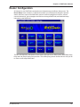
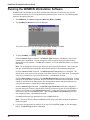
Router Configuration
All changes to your RASFinder configuration are initiated through the Router Setup menu. The
Router Setup menu consists of 13 buttons that enable you to display and change the protocol
stacks, define the output of the RASFinder, perform network management functions, test the
communications link, print messages received from the target RASFinder, and download setup
information to the RASFinder.
The two outer buttons in the bottom row are used to open the on-line Help system (RASFinder Setup
Help) and end (Exit) a Router Setup session. The middle (Retry) button remains inactive until you fail
to connect to the target RASFinder.
RF300E/RF310E
37
RASFinder RF300E/RF310E User Guide
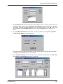
Typical Applications
The two basic applications for the RASFinder are (1) as a Remote Access Server (RAS) to permit
remote users to dial into a local area network and use the resources of that network and (2) as a
Router for LAN-to-LAN routing. The RASFinder defaults to a RAS configuration during the initial
software loading. Typical examples of both types of applications are presented in the following
paragraphs.
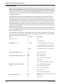
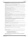
RAS Applications
During the initial software installation, the RASFinder defaults to a remote access server (RAS)
configuration. For example, the WAN Ports are connected to individual phone lines and the ports are
then configured to answer incoming calls from remote locations. Two methods of identifying remote
users are provided in the RASFinder; 1) Remote Access Dial In User Server (RADIUS) and 2) a
Remote User Data Base utility in the RASFinder software. Finally, before the application is
completely configured, the ISDN parameters have to be established for remote users can dial into the
network.
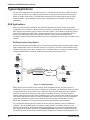
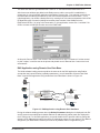
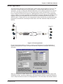
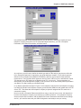
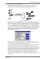
RAS Application Using Radius
RADIUS is associated with a Radius server on the network which provides a security feature using a
single authentication server to centralize security on a network. The Remote User Data Base utility
identifies each user by user name, password and, if Call Back Security is enabled, a specific phone
number the RASFinder must call to establish the connection with the remote user.
LAN
Workstation
IP Address
192.168.2.3
Network Printer
IP Address
192.168.2.4
RASFinder
IP Address
192.168.2.10
BRI 1
BRI 3
Workstation
IP Address
192.168.2.5
BRI 2
716-5467 {0716456701}
716-5567 {0716556701}
716-5468 {0716546801}
User 1
Phone
881-3100
716-5565 {0716556501}
716-5466 {0716546601}
716-5566 {0716556601}
Workstation
PSTN
User 2
Phone 875-5000
Workstation
Phone
944-7064
Radius
Server
IP Address
192.168.2.6
User 3
Workstation
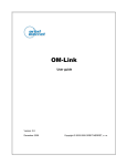
Figure 4-1. RAS Application
Before remote users can dial into the network, either the Radius security services have to be
established, or each remote user must be idenfitied in the Remote User Data Base. Radius provides
a single secure server for all remote users; whereas the Remote User Data Base utility identifies
each user by User Name, Password, and a specific Call Back Number if Call Back Security is
enabled. Radius and the Remote User Data Base have to have communication between the remote
user and the administrator either for setting up the data base or the security services to establish a
user profile. Radius also requires communication between the Radius administrator and the
RASFinder administrator to set up the security features and the Radius server address.
For a typical RAS application with a Radius server providing the network security, the Ethernet
(10Base-T) port of the RASFinder is connected to the IP network, the Radius server is on the
backbone of the network, and the WAN ports of the RASFinder are connected to individual phone
lines. During initial software installation, the Default Parameters dialog box is displayed with both
IPX and IP protocols enabled and a default Ethernet IP address and (subnet) mask displayed. For a
38
RF300E/RF310E
Chapter 4 - RASFinder Software
RAS application using Radius on an Ethernet IP network, you would disable the IPX protocol and then
change the default LAN IP address and mask to the unique IP addressing scheme for your network.
The address assigned to the Ethernet port of the RASFinder can be any address that is recognizable
by your network’s backbone.
After you enter your LAN IP address information and six sequential WAN addresses have been
automatically placed in the Remote address for WAN 1 thru WAN 6 fields, ensure that the Enable IP
Routing on each WAN port is checked. This activates the WAN ports to receive calls from the remote
users. At this point, the software will be downloaded to the RASFinder and then you will need to go in
through the main menu to set up your ISDN connection to your Public Switched Telephone Network
(PSTN) and Radius security services.
To establish your ISDN connection with your local PSTN (either the North American version or the
European version), you may have to enter some ISDN parameters, e.g., switch type used by the
PSTN, SPIDs and Directory Numbers for North America or ISDNs and sub addresses for European
and the Rest of the World (ROW). During the provisioning of the ISDN connection with your local
PSTN, the local telephone company established some ISDN parameters for your local connection. A
space is provided in Before You Start Loading your Software to document these parameters. Now, in
order to load this informtion into your RASFinder, you need to bring up the Main Menu and click on
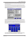
the WAN button.
From the WAN Port Setup dialog box, click on the Advanced tab to bring up the WAN Port Setup
dialog box with the ISDN TA Control group highlighting wan 1. To establish your ISDN parameters,
click on the Edit button and the ISDN Parameter Configuration dialog box is displayed.
RF300E/RF310E
39
RASFinder RF300E/RF310E User Guide
In the ISDN Parameter Configuration dialog box you can define the switch type used by the local
telephone company, data and voice TEI (Terminal Endpoint Identifier), your US or European
Parameters, Call Control Parameters, and Data Control.
At a minimum, you will have to define the switch type and the TEIs and you may have to define the
US or European Parameters if required by your local telephone company. Three switch types are
defined for the US Parameters (DMS100, AT&T5ESS, and NI1), this covers the North American
requirements. The European switch types are VN4 for France, NET3 for Euro, and INS64 for Japan.
The data and voice TEI selections are disabled, auto TEI, or zero to 63. These parameters are
determined by the local telephone company, so all you have to do is enter exactly what is provided in
the your Before You Start Loading your Software listing.
In our RAS Application example in Figure 4-1, the telephone switch at the local telephone company is
a DMS-100 and the local telephone company provisioned the ISDN lines with a data and voice TEI of
Auto TEI. This allows the local telephone company to dynamic assigned the TEIs each time a
connection is made.
Now, for the US or European Parameters which you may or may not have to enter, this depends on
how the local telephone company is provisioning your ISDN connection. If the telephone company
does not require this information, and the default Call Control Parameters and Data Control settings
or OK, you would be done with your ISDN Configuration and ready to set up your Radius security
services.
40
RF300E/RF310E
Chapter 4 - RASFinder Software
But if your local telephone company requires either SPIDs and/or Directory Numbers for the US
Parameters or ISDNs and Sub Addresses for the European Paramters, you will have to enter these
fields for each WAN port on the RASfinder. A word of caution at this point with respect to entering
this type of information, your need to ensure that these fields are filled in exactly as they are provided
from your local telephone company, because the SPID and DN or ISDN and sub address have to
correspond to the BRI line coming into the RASFinder and the WAN ports assigned to that BRI line.
For if the SPID or ISDN is not on the same BRI line that is provisioned by the local telephone
company, the call will not be completed.
A SPID (Service Profile Identifier) is a 12-digit number that is supplied by your local telephone
company which encompasses the phone number.
A Data or Voice Directory Number (DN) is the telephone number assigned to that B-channel for the
BRI line (telephone line) supplied to you by your local telephone company. If a DN is assigned, then
only the device associated with that WAN port will respond to the call.
In our RAS Application example in Figure 4-1, lets assume that telephone connection is being made
for a US (North American) network. During the provisioning phase of setting up the local ISDN
connection, the local telephone company assigned telephone number 716-5565 to the first B-channel
for BRI 1 connection. This telephone number should correspond to Wan 1 in the ISDN Parameter
Configuration dialog box. The SPID for the first B-channel is 0716556501. The telephone company
also assigned telephone number 716-5466 to the second B-channel for BRI 1 connection. The SPID
for the second B-channel is 0716546601. In our example application, the ISDN Parameter
Configuration dialog box for the US Parameters would contain Data SPID of 0716556501 and Voice
SPID of 0716546601. If you want either of these calls to be directed to the device connected to Wan
1 or Wan 2 you would also enter the telephone number in the Data or Voice Directory Num field. So
for example, if you wanted the Data SPID 0716556501 to be directed to the device on your network
associated with Wan 1, you would enter telephone number 7165565 in the Data Directory Num field
for Wan 1. If you wanted the calls directed to the second B-channel of BRI 1 to go to the device on
your network that is associated with Wan 2, you would enter telephone number 7165466 in the Voice
Directory Num field for Wan 1. When you have finished enterring the parameters for Wan 1, you click
the OK button and you will be returned to the dialog box with the ISDN TA Control group. You would
then change to the next Wan number to be configured in the ISDN Parameter Configuration dialog
box. When you have configured all three of the BRI port or the ports connected to the local
telephone company, you can begin setting up your Radius securtiy services.
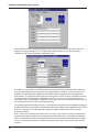
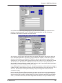
To enable the Radius security services, you need to establish communications between the Radius
server and the RASFinder. The Radius security service options are defined on the Radius Setup
RF300E/RF310E
41
RASFinder RF300E/RF310E User Guide
dialog box. To provide vendor-specific configuration for the Radius server, you need to bring up the
main menu, hit the PPP/SLIP button, and click the RADIUS button in the PPP Port Setup dialog box.
The Radius Setup dialog box enables the RADIUS option, establishes accounting, enables call if
security server is down, assigns a remote address using the RADIUS, provides a window for the
shared secret, and indicates the primary RADIUS server IP address. The new vendor specific
attributes and services that you establish for the RASFinder can not conflict with any standard Radius
attributes or any other custom attributes on the Radius Security Server. The Enable RADIUS option
enables communication between the Radius server and the RASFinder. Enable Accounting option
activates the accounting features which allow the Radius server to track the number of bytes sent
and received, login and logout times, port number, etc. The Allow Call If Security Server Down feature
can be used when the Remote User Data Base Utility is used as a backup database to the Radius
security services. The Assign Remote Address Using RADIUS feature enables the Radius server to
take over the addressing scheme of the WAN ports on the RASFinder.
The Shared Secret is an entry that must be obtained from the Radius network administrator and must
be the same as is used on the Radius security server. The RADIUS Primary Server Address is the IP
address of the Radius security server and in our typical RAS application, this address is 192.168.2.6.
If one or more backup Radius servers are used in your network, then their IP addresses need to be
entered in the Backup Server Address 1, 2, and/or 3 fields.
The Attribute Values Group at the bottom of the Radius Setup dialog box have default values for
each of the three attributes and two services.
The three new attributes are vendor-specific attributes and may have to be added to the Radius
server dictionary. The first attribute is Callback-Delay with a value of 224. The Radius server is set up
with a delay time for calling back the remote user. The Remote User Enter Number Attribute Value
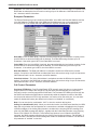
has a value of 225. This attribute specifies a telephone number of where a remote user can be called
back if he/she is not at their usual telephone number provided in their user profile. The remote user
would have to give that new phone number to the Radius network administrator so the RASFinder
will know that the remote user is at a different phone from the one in their user profile.
The Protocol Permissions Attribute has a value of 226 and the values associated with the attribute
are “1” for IP, “2” for IPX, and “3” for Spanning Tree.
The Inbound User Service Type Attribute has a value of “10” and an associated value of “6”. This
attribute enables the remote user to have inbound access to the network only; in other words, this
attribute adds inbound access to the remote user’s profile.
42
RF300E/RF310E
Chapter 4 - RASFinder Software
The Shell User Service Type Attribute has a value of “11” and also an associated value of ”6”.
After these new attributes are added to the Radius server and the user profile is established, a
remote user (in our typical RAS application with Radius, Remote User 1, for example) could call into
the RASFinder and identify themselves by their user name and password. Remote User 1, in our
typical application, can initiate a dialup session by entering their User name and password in the DialUp Networking (My Connection) dialog box and the phone number of the WAN port on the
RASFinder that User 1 is going to be connected to. In this application, remote user 1 could dial 7165565 to connect to WAN port number one on the RASFinder.
At this point, Remote User 1 has access to the services on the LAN. For instance, if he/she wanted
to print a report, it could be sent to the printer and printed out as if Remote User 1 was on the local
area network.
RAS Application using Remote User Data Base
The initial software loading process would be the same as for the RAS application using Radius,
except that now instead of setting up Radius parameters, you will assemble a Remote User Data
Base. A typical RAS application using the Remote User Data Base is shown in Figure 4-2.
LAN
Workstation
IP Address
192.168.2.3
Network Printer
IP Address
192.168.2.4
Workstation
IP Address
192.168.2.5
RASFinder
IP Address
192.168.2.10
BRI 1
BRI 3
716-5565 {0716556501}
192.168.2.11
716-5466 {0716546601}
192.168.2.12
716-5566 {0716556601}
BRI 2 192.168.2.13
716-5467 {0716456701}
192.168.2.14
716-5567 {0716556701}
192.168.2.15
716-5468 {0716546801}
192.168.2.16
Workstation
PSTN
User 2
Phone 875-5000
Workstation
Phone
944-7064
Novell File
Server
IP Address
192.168.2.6
User 1
Phone
881-3100
User 3
Workstation
Figure 4-2. RAS Application using Remote User Data Base
During the software loading process when the Default Parameters dialog box is displayed, both IPX
and IP protocols are enabled and a default Ethernet IP address and (subnet) mask are displayed in
the IP LAN group. For this RAS application, you would disable the IPX protocol and then change the
default LAN IP address and mask to the unique IP addressing scheme for your network. The address
assigned to your RASFinder’s Ethernet port can be any address that is recognizable by your
RF300E/RF310E
43
RASFinder RF300E/RF310E User Guide
network’s backbone.
In this typical RAS application, the IP network address is 192.168.2.xxx. For the purpose of this
discussion, we are assigning the IP address 192.168.2.10 to the Ethernet port on the RASFinder.
After this address is entered into the IP Address field of the Default Parameters dialog box, the next
six sequential IP addresses (192.168.2.11 thru 192.168.2.16) are assigned to the WAN ports. These
six IP addresses, in the same network (with the Ethernet LAN), are associated with the respective
WAN ports so that when the remote users dial into the WAN port, they always appear (to the rest of
the IP network) at these respective addresses.
At this point, the software will be downloaded to the RASFinder and then you will need to go in
through the main menu to set up your ISDN connection to your Public Switched Telephone Network
(PSTN) and then establish your remote user data base.
To establish your ISDN connection with your local PSTN (either the North American version or the
European version), you may have to enter some ISDN parameters, e.g., switch type used by the
PSTN, SPIDs and Directory Numbers for North America or ISDNs and sub addresses for European
and the Rest of the World (ROW). During the provisioning of the ISDN connection with your local
PSTN, the local telephone company established some ISDN parameters for your local connection. A
space is provided in Before You Start Loading your Software to document these parameters. Now, in
order to load this informtion into your RASFinder, you need to bring up the Main Menu and click on
the WAN button.
From the WAN Port Setup dialog box, click on the Advanced tab to bring up the WAN Port Setup
dialog box with the ISDN TA Control group highlighting wan 1. To establish your ISDN parameters,
click on the Edit button and the ISDN Parameter Configuration dialog box is displayed.
44
RF300E/RF310E
Chapter 4 - RASFinder Software
In the ISDN Parameter Configuration dialog box you can define the switch type used by the local
telephone company, data and voice TEI (Terminal Endpoint Identifier), your US or European
Parameters, Call Control Parameters, and Data Control.
At a minimum, you will have to define the switch type and the TEIs and you may have to define the
US or European Parameters if required by your local telephone company. Three switch types are
defined for the US Parameters (DMS100, AT&T5ESS, and NI1), this covers the North American
requirements. The European switch types are VN4 for France, NET3 for Euro, and INS64 for Japan.
The data and voice TEI selections are disabled, auto TEI, or zero to 63. These parameters are
determined by the local telephone company, so all you have to do is enter exactly what is provided in
the your Before You Start Loading your Software listing.
In our RAS Application example in Figure 4-2, the telephone switch at the local telephone company is
a DMS-100 and the local telephone company provisioned the ISDN lines with a data and voice TEI of
Auto TEI. This allows the local telephone company to dynamic assigned the TEIs each time a
connection is made.
Now, for the US or European Parameters which you may or may not have to enter, this depends on
how the local telephone company is provisioning your ISDN connection. If the telephone company
does not require this information, and the default Call Control Parameters and Data Control settings
or OK, you would be done with your ISDN Configuration and ready to set up your Radius security
RF300E/RF310E
45
RASFinder RF300E/RF310E User Guide
services.
But if your local telephone company requires either SPIDs and/or Directory Numbers for the US
Parameters or ISDNs and Sub Addresses for the European Paramters, you will have to enter these
fields for each WAN port on the RASfinder. A word of caution at this point with respect to entering this
type of information, your need to ensure that these fields are filled in exactly as they are provided
from your local telephone company, because the SPID and DN or ISDN and sub address have to
correspond to the BRI line coming into the RASFinder and the WAN ports assigned to that BRI line.
For if the SPID or ISDN is not on the same BRI line that is provisioned by the local telephone
company, the call will not be completed.
A SPID (Service Profile Identifier) is a 12-digit number that is supplied by your local telephone
company which encompasses the phone number.
A Data or Voice Directory Number (DN) is the telephone number assigned to that B-channel for the
BRI line (telephone line) supplied to you by your local telephone company. If a DN is assigned, then
only the device associated with that WAN port will respond to the call.
In our RAS Application example in Figure 4-2, lets assume that telephone connection is being made
for a US (North American) network. During the provisioning phase of setting up the local ISDN
connection, the local telephone company assigned telephone number 716-5565 to the first B-channel
for BRI 1 connection. This telephone number should correspond to Wan 1 in the ISDN Parameter
Configuration dialog box. The SPID for the first B-channel is 0716556501. The telephone company
also assigned telephone number 716-5466 to the second B-channel for BRI 1 connection. The SPID
for the second B-channel is 0716546601. In our example application, the ISDN Parameter
Configuration dialog box for the US Parameters would contain Data SPID of 0716556501 and Voice
SPID of 0716546601. If you want either of these calls to be directed to the device connected to Wan
1 or Wan 2 you would also enter the telephone number in the Data or Voice Directory Num field. So
for example, if you wanted the Data SPID 0716556501 to be directed to the device on your network
associated with Wan 1, you would enter telephone number 7165565 in the Data Directory Num field
for Wan 1. If you wanted the calls directed to the second B-channel of BRI 1 to go to the device on
your network that is associated with Wan 2, you would enter telephone number 7165466 in the Voice
Directory Num field for Wan 1. When you have finished enterring the parameters for Wan 1, you click
the OK button and you will be returned to the dialog box with the ISDN TA Control group. You would
then change to the next Wan number to be configured in the ISDN Parameter Configuration dialog
box. When you have configured all three of the BRI port or the ports connected to the local telephone
company, you can begin setting up your Radius securtiy services.
46
RF300E/RF310E
Chapter 4 - RASFinder Software
Before remote users can dial into the network, a user profile has to be set up in the proprietary
remote user database using the Remote User Data base utility. This data base utility is provided with
the RASFinder software. The RASFinder network administrator builds this database by adding
information (for one remote user at a time) via the Add Users dialog box. The user name and
password in this application must be negotiated between the RASFinder administrator and each
remote user.
User names can be up to 39 characters long, with any printable characters; however, no spaces are
allowed within the names. In our dialog box (above), we are using the User Name “User2.” The
letters will appear as all caps in the Users List; however, dial-in applications will treat the user names
as case-insensitive strings, enabling the users to enter their user names as all uppercase, all
lowercase, or a mixture of uppercase and lowercase.
A User Password of up to 7 characters should be given each user. In the Call Back group, the Call
Back option should be enabled (checked) for security purposes. If ONLY this option is checked, the
remote user would be asked to supply the callback numbers when they dial into the RASFinder. If
Call Back Security Enabled is also checked, the administrator controls the callback numbers through
the Call Back Number field. In our typical application, User 2’s phone number is 875-5000; therefore,
we enter this number in the Call Back Number field. In the Dial In Ports, we have assigned User2 to
WAN Port 2 with phone number 716-5466 assigned to it. This phone number will have to be entered
in the Phone Number field on remote User 2’s dial-up networking (My Connection) dialog box.
After the Add Users dialog box is filled in, you need to click the Rights button which brings up the
User Permissions dialog box.
The User Permissions dialog box enables you to assign protocol’s, user service type(s), time limits,
and time of day for each user to login. The Auto Protocols allow for no auto login, login via Telnet, or
RF300E/RF310E
47
RASFinder RF300E/RF310E User Guide
RLogin and then direct the remote user to a specific host. The User Service Types defines how the
remote user is going to be allowed to use the network. For example, a remote user could be allowed
Inbound Permissions using Telnet, or Inbound using Rlogin. The time of day and days in which the
user can access the network are the final items in the User Permissions dialog box. Once this is
established for each user and the user database is loaded into the RASFinder, all the remote users
can dial into the network and access the network resources according to the restrictions/permissions
on this dialog box.
For example, Remote User2 (in our typical application) could initiate a dialup session by merely
entering their User name and password in the Dial-Up Networking (My Connection) dialog box (see
below) after having first set up a New Connection (called “My Connection”) and entering the phone
number of RASFinder WAN port 2 (716-5466), which is assigned to User2.
Once Remote User2 has connected and been authenticated, they have access to the services on the
LAN. For instance, if he/she wanted to print a report, it could be sent to the printer and printed out just
as if Remote User2 was on the local area network.
48
RF300E/RF310E
Chapter 4 - RASFinder Software
Router Application
The second basic application for the RASFinder is LAN-to-LAN routing as shown in Figure 4-3. The
RASFinder is initially configured for a RAS application. To configure the RASFinder for a router
application, you have to change the WAN port addresses to be on a different network from the LAN
port. The remote WAN ports have to be on the same network as the local WAN ports. You would
have to change the Remote Port setup from a RAS application (Client only) to a routing application
(Client or LAN). If your routing application would benefit from having the B-channels of a BRI line tied
together to double your Wan speed, then you would have to enable the MultiLink Point-to-point
(MLPPP) option. Finally, before you can route between LANs you would have to establish the ISDN
parameters for the BRI line connecting the RASFinder to the Public Switched Telephone Network
(PSTN).
LAN
Remote Office
LAN
Workstation
IP Address
192.168.2.3
Workstation
IP Address
200.2.9.5
Network Printer
IP Address
192.168.2.4
RASFinder
IP Address
192.168.2.1
Workstation
IP Address
192.168.2.5
716-5566 {0716556601}
192.168.4.10
BRI 1
716-5467 {0716456701}
192.168.4.10
881-3200 {0881320001}
PSTN
192.168.4.20
881-3201 {0881320101}
BRI 1
IP Address
200.2.9.1
Network Printer
IP Address
200.2.9.6
192.168.4.20
Workstation
IP Address
200.2.9.7
Workstation
IP Address
200.2.9.8
Novell File
Server
IP Address
192.168.2.6
Figure 4-3. Router Application
During initial software loading, you begin to configure the RASFinder for a routing application. A
typical routing application is shown in Figure 4-3 and will be used as an example in the following
discussion.
When you changed your LAN IP address in the Default Parameters dialog box to your unique LAN
addressing structure, the Remote Addresses in the WAN group will change to sequential addresses
of the LAN port which will not work in a routing application. The initial setup of the software defaults
RF300E/RF310E
49
RASFinder RF300E/RF310E User Guide
to a RAS application. The Default Parameters dialog box will not allow you to change the addressing
scheme of the remote WAN ports to your unique addressing structure for your routing application.
Therefore, you have to leave the Default Parameters dialog box set up for a RAS application initially
(during initial software installation and configuration); then later, from the main menu, you can switch
your associated WAN ports from a RAS application to a routing application.
At this point, the software will be downloaded to the RASFinder and then you will need to go in
through the main menu to change the Remote Port setup group from a Client Only (RAS application)
to Client or LAN option for the WAN ports you need for routing, then you will be able to change those
WAN ports to a different network address than your LAN port, and finally, set up your ISDN
parameters for the BRI line connecting the RASFinder to the PSTN.
Before you can change your Wan ports to a different network than the LAN port, you have to click on
the PPP/SLIP (Point-to-Point/Serial Line Internet Protocol) button on the Main menu and the PPP
Port Setup dialog box is displayed with the WAN 1 active. In the Remote Port Setup group in the
lower right of the dialog box, change from the Client only option to the Client or LAN; this disables
RAS, and enables the RASFinder to communicate with either a remote client (PC) or a LAN for
routing. The WANs group must have the Client or LAN enabled for each of the ports that are
providing routing.
50
RF300E/RF310E
Chapter 4 - RASFinder Software
Now, you can decide if you want the B-channels of the BRI line bonded together or if you want each
B-channel to act alone. To bond the two B-channels of a BRI line together, you click on the Advanced
tab and esure that MLPPP (MultiLink Point-to-Point Protocol) option is active.
If you were to bond BRI 1 line in our Router application in Figure 4-3, you would have to change the
IP addresses (WAN 1 from 192.168.2.2 and WAN 2 from 192.168.2.3 on the Corporate LAN to the
same IP address, for example, you could use 192.168.4.10 for both B-channels. At the remote office
LAN you would then have to change BRI 1 line to say 192.168.4.20.
Now, to configure the RASFinder for the routing application as shown in Figure 4-3 and bonding the
B-channels together, you need to click on the IP button on the Main Menu. The IP Port Setup dialog
box is displayed with the Ethernet tab active showing your LAN IP address.
Next, you need to click on the WAN tab to display the Port Address and Remote Address groups for
WAN 1. Wan 1 is highlighted in the List of WAN ports on the right side of the dialog box. The default
WAN IP addresses will be displayed in the dialog box that were set up during the software loading
and initial configuration of the RASFinder. But, now you can change these addresses to fit your
routing application. Above I stated that we could bond the B-channels together, so here is where we
enter that information. For the Corporate LAN with the B-channels of BRI 1 bonded together and an
IP address of 192.168.4.10, you would enter this in the IP Address field for the Port Address group.
Set up your IP Mask accordingly, and then enter your IP Address for the Remote Office in the IP
Address field of the Remote Address group (192.168.4.20).
RF300E/RF310E
51
RASFinder RF300E/RF310E User Guide
Now, you can click on WAN 2 and enter the same information for the Port and Remote Address
groups. This will bond the two B-channels of BRI 1 together.
To set up the remote office LAN, go through the same process except point the WAN ports toward
the Corporate LAN. The remote WAN ports could be set up with an IP address of 192.168.4.20.
Now to establish your ISDN connection with your local PSTN (either the North American version or
the European version), you may have to enter some ISDN parameters, e.g., switch type used by the
PSTN, SPIDs and Directory Numbers for North America or ISDNs and sub addresses for European
and the Rest of the World (ROW). During the provisioning of the ISDN connection with your local
PSTN, the local telephone company established some ISDN parameters for your local connection. A
space is provided in Before You Start Loading your Software to document these parameters. Now, in
order to load this informtion into your RASFinder, you need to bring up the Main Menu and click on
the WAN button.
From the WAN Port Setup dialog box, click on the Advanced tab to bring up the WAN Port Setup
dialog box with the ISDN TA Control group highlighting WAN 1. To establish your ISDN parameters,
click on the Edit button and the ISDN Parameter Configuration dialog box is displayed.
52
RF300E/RF310E
Chapter 4 - RASFinder Software
In the ISDN Parameter Configuration dialog box you can define the switch type used by the local
telephone company, data and voice TEI (Terminal Endpoint Identifier), your US or European
Parameters, Call Control Parameters, and Data Control.
At a minimum, you will have to define the switch type and the TEIs and you may have to define the
US or European Parameters if required by your local telephone company. Three switch types are
defined for the US Parameters (DMS100, AT&T5ESS, and NI1), this covers the North American
requirements. The European switch types are VN4 for France, NET3 for Euro, and INS64 for Japan.
The data and voice TEI selections are disabled, auto TEI, or zero to 63. These parameters are
determined by the local telephone company, so all you have to do is enter exactly what is provided in
your Before You Start Loading your Software listing.
In our Router Application example in Figure 4-3, the telephone switch at the local telephone company
is a DMS-100 and the local telephone company provisioned the ISDN lines with a data and voice TEI
of Auto TEI. This allows the local telephone company to dynamic assigned the TEIs each time a
connection is made.
Now, for the US or European Parameters which you may or may not have to enter, this depends on
how the local telephone company is provisioning your ISDN connection. If the telephone company
does not require this information, and the default Call Control Parameters and Data Control settings
are OK, you would be done with your ISDN Configuration and ready to start your routing.
RF300E/RF310E
53
RASFinder RF300E/RF310E User Guide
But, if your local telephone company requires either SPIDs and/or Directory Numbers for the US
Parameters or ISDNs and Sub Addresses for the European Paramters, you will have to enter these
fields for each WAN port on the RASfinder. A word of caution at this point with respect to entering
this type of information, your need to ensure that these fields are filled in exactly as they are provided
from your local telephone company, because the SPID and DN or ISDN and sub address have to
correspond to the BRI line coming into the RASFinder and the WAN ports assigned to that BRI line.
For if the SPID or ISDN is not on the same BRI line that is provisioned by the local telephone
company, the call will not be completed.
A SPID (Service Profile Identifier) is a number supplied by your local telephone company which
encompasses the phone number.
A Data or Voice Directory Number (DN) is the telephone number assigned to that B-channel for the
BRI line (telephone line) supplied by your local telephone company. If a DN is assigned, then only
the device associated with that WAN port will respond to the call.
In our Router Application example in Figure 4-3, lets assume that telephone connection is being
made for a US (North American) network. During the provisioning phase of setting up the local ISDN
connection, the local telephone company used telephone number 716-5565 for WAN 1 of BRI 1. This
telephone number should correspond to Wan 1 in the ISDN Parameter Configuration dialog box.
The SPID for the first B-channel (WAN 1) could be 0716556501. The telephone company also used
telephone number 716-5466 for the second B-channel (WAN 2) of BRI 1. The SPID for the second
B-channel could be 0716546601. In our example application, the ISDN Parameter Configuration
dialog box for the US Parameters would contain Data SPID of 0716556501 and Voice SPID of
0716546601. If you want either of these calls to be connected to Wan 1 or Wan 2 you would also
enter the telephone number in the Data or Voice Directory Num field. So for example, if you wanted
the Data SPID 0716556501 to be directed to Wan 1, you would enter telephone number 7165565 in
the Data Directory Num field for Wan 1. If you wanted the calls directed to the second B-channel of
BRI 1 to go to Wan 2, you would enter telephone number 7165466 in the Voice Directory Num field
for Wan 2. When you have finished enterring the parameters for Wan 1, you click the OK button and
you will be returned to the dialog box with the ISDN TA Control group. You would then change to
WAN 2 and configure the ISDN Parameter Configuration dialog box. When you have configured both
BRI ports connected to the local telephone company, you are now ready to start routing between
LANs.
54
RF300E/RF310E
Chapter 4 - RASFinder Software
IP Setup
The IP Port Setup dialog box enables you to change the IP routing capabilities that were set up
during software installation. This dialog box has three tabs: Ethernet, WAN, and Advanced.
The Ethernet tab enables you to configure two parameters relating to the Ethernet port. For
example, you can change the Ethernet port IP Address and IP mask.
WAN Tab
If you enable the IP routing master control on the Advanced tab but disable the control on this tab, all
IP packets received or to be transmitted on this WAN port will be discarded. Even if bridging is
enabled, the packets will not get across the link.
The Unnumbered Link option can be selected (checked) for the WAN ports for point-to-point links.
When selected, it disables the Port Address and Remote Address groups. Unnumbered links are
useful only between two routers; in this case, local and remote. When running RIP over a PPP link,
both ends of the link must be either unnumbered or numbered with the same IP subnet. An
advantage of not assigning an IP address to each WAN port is that you conserve valuable network
and subnet numbers.
RF300E/RF310E
55
RASFinder RF300E/RF310E User Guide
Remote IP Address defines the IP address for the destination end of a point-to-point link and is
necessary only if the selected WAN port has been enabled for point-to-point operation.
Note: the remote IP address must fall within the same IP network as the local WAN IP address.
The Advanced tab is used to enable IP routing and RIP authentication and defines how the Dynamic
Host Configuration Protocol (DHCP) and Domain Name System (DNS) servers are to be used. This
tab is also used to set up the default route, any filters, and Static Routes.
The Routing option is normally checked; however, if you do not wish to have IP packets routed, then
uncheck this item. If IP routing is disabled and bridging is enabled, IP packets are bridged; i.e., IP
packets are transferred.
The RIP option enables RIP based routing. RIP (Routing Information Protocol) is a protocol used
among routers to exchange routing table information. RIP is the most common protocol used in both
IP and IPX networks. It is also used internally by client workstations in IPX networks to obtain routes
(shortest, or otherwise) to any distant network. RIP based routing should normally be enabled. It can
be disabled, however, if you are using WAN links in Dial on Demand mode. For DOD links, disabling
RIP will reduce traffic on the link as it will also disable periodic RIP broadcasts. RIP routing on a given
port will be automatically turned off when Dial on Demand is enabled on the PPP Port Setup tab for
the WAN port.
The DHCP (Dynamic Host Configuration Protocol) group enables you to set up the WAN ports as
client-only. Then, a PPP client connected to the WAN port will be on the same IP network as the LAN
port of the RASFinder. This feature can save some extra IP addresses that otherwise would have
been taken up by the WAN port. Enabling the Client option allows the RASFinder to dynamically get
an IP address for a PPP client coming up on one of its “Client-only” WAN ports. When this option is
enabled, there must be a DHCP server or a DHCP relay agent on the connected LAN in order for the
RASFinder to acquire an appropriate IP address.
When the router is configured for remote access, the DNS Resolver needs to be enabled so that
applications such as the terminal server will support Domain Names. The dotted decimal IP address
of the Local DNS server should be entered in the field provided.
The Static Routes feature allows a router to direct packets from the local network down a predefined
path (static route) to a remote network. Static routing is normally used when a part of an internetwork
can be reached by only one particular path. Static routes are manually configured routes that specify
the transmission path a data packet must follow based on the data packet’s destination address. A
static route can be setup on the corporate network so that a client pc on the manufacturing network
56
RF300E/RF310E
Chapter 4 - RASFinder Software
could send a document to the corporate printer.
This static route is shown in the top network in Figure 4-4. A static route can also use an
unnumbered link to provide a particular route for a remote server to appear as a server on the
corporate network. The unnumbered link is shown in the middle network in Figure 4-4.
Corporate
LAN
Client PC
Remote Network
Workstation
IP Address
192.168.2.3
Client PC
IP Address - 200.1.1.10
Subnet mask - 255.255.255.0
Default Gateway - 200.1.1.1
RASFinder or Router
IP Address - 200.1.1.1
Subnet mask - 255.255.255.0
WAN Local - 200.2.10.2
WAN Remote - 200.2.10.1
RASFinder
IP Address
192.168.2.10
Network Printer
IP Address
192.168.2.4
BRI 1
Hub
BRI 2
BRI 3
0716556501
0716546601
0716556601
0716456701
0716556701
0716546801
200.2.10.1
200.2.10.1
200.2.12.1
200.2.12.1
200.2.10.2
Phone
881-3100
Hub
RAS
or
Router
PSTN
Radius
Server
IP Address
192.168.2.6
Publications
Network
Hub
Manuals Server
IP Address - 192.168.2.226
Subnet mask - 255.255.255.224
Default Gateway - 192.168.2.225
IP Address - 192.168.2.225
Subnet mask - 255.255.255.224
WAN Local - Unnumbered
200.2.12.2
Internet Router
IP Address
192.168.2.220
Manufacturing
Network
RAS
or
Router
Phone
944-7064
RAS
or
Router
Tech Support
Network
Hub
202.1.1.xxx
Figure 4-4. Static Routes
In our first example above, where a data packet from the remote client PC on the manufacturing
network is being sent to the corporate printer, a static route would be established on the corporate
RASFinder to have WAN 1 and WAN 2 with network address of 200.2.10.1 and a gateway address of
200.2.10.2, the remote network. The Static Routes Setup dialog box would contain the address of
200.1.1.0 in the IP Address field and a gateway address of 200.2.10.2. The Unnumbered option
would be left unchecked in this example. The IP Address field contains the address of the target host
or network, a PC on the manufacturing network. The Gateway Address is the address of the local
router on the manufacturing network (200.2.10.2) on the next hop toward the target host. The
Address Mask is the IP subnetwork mask (255.255.255.0) of the target host. The Port field is
inactive, greyed out in this example.
This example establishes a static (direct) path for the user on the client pc on the manufacturing
network to send a letter to the corporate LAN and have it printed on the corporate network printer.
The control for this static path is the RASFinder on the corporate LAN.
Now, for our second example of an unnumbered link where we want a server on a remote network to
appear as a device on the corporate LAN. Lets use the example of the Internet router on the
corporate network wanting to provide manuals from the Publications network to Internet users. Lets
say that the Manuals Server on the Publications Network contains released manuals that a customer
can down load from the corporate network. So in order to have the Manuals Server appear on the
Internet router, we need to set up the corporate RASFinder with an unnumbered link and for the
purposes of our example, lets use the middle two WAN ports (WAN 3 and WAN 4). Also, the
Internet router will have a default route of 192.168.2.224 with a subnet Address Mask of
255.255.255.224, and a Gateway Address of 192.168.2.10. The Manuals server would need a
gateway pointing to the corporate RASFinder. The gateway address on the Manuals server could be
192.168.2.225.
RF300E/RF310E
57
RASFinder RF300E/RF310E User Guide
So, for this application to work, you need to set up a static route on the Corporate RASFinder of
192.168.2.220 which is pointing at the Internet router. You then need to go into the IP Port Setup
dialog box, select WAN tab, highlight WAN 3, and activate the Unnumbered Link option. Then do the
same thing for WAN 4. When you do this, the Port Address and the Remote Address groups become
inactive. Now, you need to check the PPP/SLIP button on the Main menu and ensure that the
Remote Port Setup group for WAN 3 and WAN 4 are set to Client or LAN.
Now go back to the IP Port Setup dialog box and hit on the Advance tab, then click on the Static
Routes button. This brings up a blank IP Static Routes dialog box, hit the Add button to bring up the
Static Routes Setup dialog box and when you enable the Unnumbered option, the Gateway Address
option becomes inactive.
Now, for the IP Address field we want the address of the Internet router on the Corporate LAN which
in our unnumbered example is 192.168.2.224. In order for the Manuals server on the Publications
network to appear on the Corporate LAN, we need to subnet the Manuals server with an Address
Mask of 255.255.255.224. The Port option identifies the WAN ports on the Corporate RASFinder that
are unnumbered. In our example, WAN 3 and WAN 4 are the unnumbered ports. So you would
develop the Static Routes Setup dialog with WAN 3 as the WAN port and establish a second Static
Routes Setup dialog with the only change from the above dialog box is that WAN 4 is the port
number.
When we click on the OK button for the second Static Routes Setup dialog box, the IP Static Routes
dialog box now displays two examples of static routes.
To complete the Static Route application, the Publications network RASFinder or router, depending
on the type of device used on the network would need a default route of 192.168.2.226 that is looking
at the Manuals Server. The Ethernet port IP address could be 192.168.2.225 with a net mask of
255.255.255.224.
58
RF300E/RF310E
Chapter 4 - RASFinder Software
Filters
The network administrator can set up filters on the RASFinder for better control. Filtering can be used
when you want to block all packets originating from a specific destination (called source address
filtering) or all packets heading for a particular destination (called destination address filtering). Filters
can be set up to exclude packets of a particular protocol (TCP or UDP) or any particular field in a
LAN packet. The IP Filtering Setup dialog box lists the port, address, or Internet Control Message
Protocol (ICMP) filtering for the IP protocol.
Initially, the filtering list window, i.e., the window area that displays the Type, Port, Protocol, and
Protocol Port information is blank. This information is displayed in the window when the Add/Edit IP
Port or Address Filter dialog box is filled out.
Note: When filters are installed, the RASFinder needs to do extra processing (i.e., it needs to look
into each packet that has to be routed or bridged). Thus, installing too many filters may lead to
performance degradation.
Port filtering filters or forwards IP packets based on their specific purpose; i.e., whether they are
Telnet (TCP based) or TFTP (UDP based) packets. Address filtering filters or forwards packets
based on their source or destination IP address. Separate filtering support is provided for specific
kinds of received ICMP packets.
The filtering list window on the Port Filtering tab (above) displays the filter Type, the physical Port
(LAN, or one of the WAN ports), the Protocol (TCP or UDP), and the Protocol Port. On the Address
Filtering tab (not shown), the Protocol and Protocol Port columns are replaced by IP Address.
To add or edit a filter listing, the Add/Edit IP Port (Address) Filter dialog box is used. This dialog
box enables you to create an entry which is then displayed in the filtering list window. In the example
Add/Edit IP Port Filter dialog box, the protocol that is going to be filterred is TCP, the physical port on
RF300E/RF310E
59
RASFinder RF300E/RF310E User Guide
which the filtering is going to take place is the LAN port, the protocol port is telnet which translates
into protocol port number 0023 in the filtering list window, and the filter type is Filter on Destination
Port which means to drop all IP packets whose destination protocol port is telnet.
Address filtering uses the IP address in the IP Address field (example, packets with address
192.168.2.40), applies filtering to the physical port listed in the Physical Port field (LAN), and if the
Filter Type is Filter on Destination Address that means that all packets with an IP address of
192.168.2.40 that are destined for the LAN port are blocked.
ICMP filtering provides separate filtering support for specific kinds of received ICMP packets. ICMP
filtering is used in IP networks as an internal protocol for nodes to exchange control and diagnostic
information. Applications normally do not use ICMP filtering for any purpose.
You can select ICMP filtering on your LAN or WAN ports and the type of filtering on each port by
choosing the filtering type from the ICMP Packet Types list.
60
RF300E/RF310E
Chapter 4 - RASFinder Software
IPX Setup
The IPX Virtual Port Setup dialog box is used to control the four frame types and set up the WAN
ports of the RASFinder. The Advanced tab opens an IPX general setup window used to enable or
disable IPX routing and autolearn of Ethernet network numbers.
In IPX based networks using Ethernet, LAN segments can support the use of four different Ethernet
frame formats over the same physical link (provided each frame type has a unique network address
as a virtual port).
The Wan tab allows you to enable or disable IPX routing on the WAN ports and change the network
number for the WAN ports. The IPX WAN network number has to be the same on both ends of the
link and must be unique throughout the internetwork. If a WAN port is configured in a point-to-point
operation, both WAN network numbers have to be the same and unique.
NetBIOS, when enabled, enables the transport of Novell encapsulated NetBIOS packets on the
specified virtual IPX port. Refer to Novell documentation regarding NetBIOS operation over NetWare
based LANs.
The Advanced tab controls the master routing of the protocol and auto learn of Ethernet network
numbers, defines the broadcast name of the RASFinder, and enables IPX filtering.
RF300E/RF310E
61
RASFinder RF300E/RF310E User Guide
If bridging of IPX packets is desired, IPX routing must be disabled and frame type support for the
frame type must be enabled.
If there is a server on the local segment, then IPX network number auto learn should be enabled. If
there is no server, or if for some reason the RASFinder comes up before the server does, the
RASFinder will default to some random network numbers after a short period of time.
IPX Filters
The network administrator can set up filters on the RASFinder for better control. IPX packet filtering
can be set up to selectively filter or forward packets based on the IPX address.
Filtering can be used when you want to block all packets originating from a specific destination
(called source address filtering) or all packets heading for a particular destination (called destination
address filtering). Filters can be set up to exclude packets of a specific port. The IPX Filtering Setup
dialog box lists the filter type, port, and IPX address. Initially, the filtering list window, i.e., the window
area that displays the Filter Type, Port, and IPX Address information is blank. This information is
displayed in the window when the Add/Edit IPX filter dialog box is filled out.
Note: When filters are installed, the RASFinder needs to do extra processing (i.e., it needs to look
into each packet that has to be routed or bridged). Thus, installing too many filters may lead to
performance degradation.
The Add or Edit IPX Filter dialog box allows you to enter a network number and node number, and
define a socket number, physical port, and filter type. The Network Number defines the physical port
which is defined by turning off AutoLearn Ethernet Network Numbers option in the IPX Virtual Port
Setup dialog box under the Advanced tab. The Node Number is a 12-digit alphanumeric MAC
Address of the Ethernet NIC that is providing your Ethernet interface. The Node Number is defined in
the IP Configuration dialog box under the Adapter Address in the Ethernet Adapter Information group.
The Adapter Address is presented with dashes between each set of two alphanumeric digits. These
dashes can not be used in the Node Number. The IP Configuration dialog box is accessed from a
DOS prompt by enterring winipcfg.
The socket number, physical port, and filter type are provided in drop down lists. Three socket
number selection are provided; NCP, RIP, and SAP. The physical port lists the available port for
which filtering can be accomplished; LAN and the WAN ports. The filter type defines whether you are
going to forward or filter depending on the source or destination address.
62
RF300E/RF310E
Chapter 4 - RASFinder Software
Spanning Tree Setup
This dialog box lets you configure the parameters for transparent bridging or bridging using Spanning
Tree Algorithm as specified in IEEE 802.1d standard. Transparent bridging occurs between two
remote Ethernet LANs.
Spanning Tree Algorithm is a protocol specified by the IEEE 802.1d standard for use by bridges to
perform bridging. Bridges implementing this protocol interact with each other so as to prevent
bridging-loops in an internetwork with redundant links to the same networks. This algorithm also
allows for automatic use of alternative routes (provided there are redundant paths to the destination)
in case the original route is unavailable for some reason.
Bridging needs to be enabled to support networking protocols such as NetBIOS. However, if you are
using only IP and IPX, the RASFinder will operate more efficiently if you leave bridging disabled.
The Filters button enables the construction of a filtering database. Packets whose Ethernet source
address or destination address is not found in the filtering database will either be filtered or
forwarded, depending on the setting of the Default Action field, with a default setting of “forward.”
Filtering can be used when you want to block all packets originating from a specific destination
(called source address filtering) or all packets heading for a particular destination (called destination
address filtering). Filters can be set up to exclude packets of a specific port. The Spanning Tree
Filtering Setup dialog box lists the filters by filter type, port, and Ethernet address. Initially, the
filtering list widow, i.e., the window area that displays the Filter Type, Port, and Ethernet Address
information is blank. This information is displayed in the window when the Add/Edit Spanning Tree
Filter dialog box is filled out.
Note: When filters are installed, the RASFinder needs to do extra processing (i.e., it needs to look
into each packet that has to be routed or bridged). Thus, installing too many filters may lead to
performance degradation.
The add or edit Spanning Tree Filter dialog box allows you to enter the Ethernet address (for
example 00015345678) to which you want to apply filtering, the physical port (WAN 1) on which the
filtering is going to be applied, and the filter type in our example of Filter Destingation Address.
RF300E/RF310E
63
RASFinder RF300E/RF310E User Guide
This means that all packets with a destination address of 00015345678 going to WAN 1 are dropped.
64
RF300E/RF310E
Chapter 4 - RASFinder Software
WAN Port Setup
The WAN Port Setup dialog box controls how each WAN port is configured. The options at the top
of the dialog box (i.e., Port Enable, Needs Dial Backup, and the Scripting options) can be assigned to
each port listed in the Wans group in the lower right part of the dialog box. The Connection Method
can be set for either Answering or Dialing for each port listed in the Wans group. When the dialing
option is selected, the Asynchronous Gateway Server [AG Server] and Terminal Server groups
become inactive. To configure a WAN port for dial backup, you need to click on the Needs Dial
Backup option and then click on the Backup Port tab and enter the call back phone number, WAN
port, and priority of the call.
If a WAN port Needs Dial Backup in case it loses carrier (i.e., the Carrier signal, DCD, goes down),
then Wan 6 is dedicated for this purpose. Therefore, five of the six WAN port can be used for dial
backup. When the Needs Dial Backup option is selected, the call back number needs to be enterred
in the Dial Number field of the Backup Parameters. The WAN port number has to be specified and
the priority of the call back has to be specified. The call back priority ranges from No Priority to four.
The Script button provides access to the scripting options. The Script Dialog menu enables you to
edit, compile and download scripts. A script file (a text file containing a sequence of commands; refer
RF300E/RF310E
65
RASFinder RF300E/RF310E User Guide
to Appendix B) can be used to automate certain RASFinder operations. The Script Enable or
Restart Script On Communications Failure option can be used to either start scripting or restart a
script upon failure.
The RASFinder has built-in support for Multi-Tech Communication Services Interface Server (MCSI,
NASI, NCSI, or AG server) if every asynchronous communication line across the internetwork has a
unique MCSI name. If you set the Connection Method for Answering, the Asynchronous Gateway
Server (AG Server) group becomes active, enabling you to set the General Name and Specific
Name of the interface corresponding to that specific WAN Port. The name of the AG Server is
assumed to be the same as the IPX router name (or at least the first eight characters of the Router
Name entered on the Default Parameters dialog box during initial configuration). The General Name
can be any 8 alphanumeric characters (with no question marks) and the Specific Name can be any
14 alphanumeric characters (with no question marks).
Setting the Connection Method for Answering also activates the Terminal Server group, where you
need to enter, in the field provided, the dotted decimal IP Address of the default Telnet server.
From the Advanced tab, you can define the parameters for each WAN port, i.e., whether it is an
ISDN parameter or a modem parameter. In defining the ISDN TA Control parameters, you highlight
the WAN number and click on the Edit button. To define the modem parameters for the five out of six
modems, you enter the modem string in the appropriate String number corresponding to the WAN
port selected the Wan tab.
When you select the Wan port in the ISDN TA Control group and click on the Edit button, the ISDN
Parameter Configuration dialog box is displayed with the Wan port number displayed in the Config
name field. The Config name field is greyed out so that it can not be changed.
66
RF300E/RF310E
Chapter 4 - RASFinder Software
This dialog box displays the network switch type and the US Parameters or the Europe Parameters,
depending on the switch type selected. In the first example (above), the default US Parameters are
displayed and are available for editing purposes. The Net Switch Type is also unavailable as it is the
switch type that was defined for this particular configuration.
General Parameters
Data TEI (Terminal Endpoint Identifier) - You may have received a fixed TEI (a number from 0 to 63)
from your provider; if so, then select that number from the list in the Data TEI box. However, if the
central office switch assigns a dynamic TEI each time your RASFinder connects to the network, then
leave it set to the default, “Auto TEI.” If you have multiple RASFinders attached to a network
terminator bus, you may want to set the Data TEI to ”Disabled.”
Voice TEI - You may have received a fixed TEI (a number from 0 to 63) from your provider; if so, then
select that number from the list in the Voice TEI box. However, if the central office switch assigns a
TEI each time your RASFinder connects to the network, then leave it set to “Auto TEI.” Again, if you
have multiple RASFinders attached to a network terminator bus, you may want to set the Voice TEI
to “Disabled.”
US Parameters
The US Parameters group includes the Data SPID, Voice SPID, the data Directory Number (DN),
and the voice DN. The SPIDs and Directory Numbers may not be required by your service provider;
but, if they are required, the fields are defined below.
Data SPID (Service Profile Identifier) - Enter the Data SPID, if required, that was assigned by the
local phone company for the specific BRI line to which the RASFinder is attached. The Data SPID
string can have up to 20 characters. For DMS-100 switches, any ASCII character except the
underline (_) is valid; For NI-1 and AT&T switches, only the digits 0-9 are valid.
Voice SPID - Enter the Voice SPID, if required, that was assigned by the local phone company for
the specific BRI line to which the RASFinder is attached. The Voice SPID string can have up to 20
characters. For DMS-100 switches, any ASCII character except the underline (_) is valid; For NI-1
and AT&T switches, only the digits 0-9 are valid.
Data Directory Number (DN) - The data DN is a telephone number the ISDN service provider
assigns, if required, to the RASFinder at subscription time; this can be a string of up to 24 characters.
Valid characters are 0-9, the * character, and the # character.
RF300E/RF310E
67
RASFinder RF300E/RF310E User Guide
Voice DN - The voice DN is a telephone number the ISDN service provider assigns, if required, to the
RASFinder at subscription time; this can be a string of up to 24 characters. Valid characters are 0-9,
the * character, and the # character.
European Parameters
The Europe Parameters group includes the Data ISDN, Voice ISDN, the Data Sub Address, and the
voice Sub Address. The Data and Voice ISDNs and Sub Addresses may not be required by your
service provider. If the ISDNs and Sub Addresses are required, the fields are defined below.
Data ISDN - Enter the Data ISDN, if required, that was assigned by the local phone company for the
specific BRI line to which the RASFinder is attached. The Data ISDN string can have up to 20
characters. If the switch type is NET3, the Data ISDN is not used.
Voice ISDN- Enter the Voice ISDN, if required, that was assigned by the local phone company for the
specific BRI line to which the RASFinder is attached. The Voice ISDN string can have up to 20
characters. If the switch type is NET3, the Voice ISDN is not used.
Data Sub Address - The Data Sub Address is a telephone number the ISDN service provider
assigns, if required, to the RASFinder at subscription time; this can be a string of up to 24 characters.
Valid characters are 0-9, the * character, and the # character.
Voice Sub Address - The Voice Sub Address is a telephone number the ISDN service provider
assigns, if required, to the RASFinder at subscription time; this can be a string of up to 24 characters.
Valid characters are 0-9, the * character, and the # character.
Call Control Parameters
Persistent DTR Dialing - Data Terminal Ready (DTR) normally goes high when a communication
program starts or is ready to dial. A high DTR on the serial port indicates that your computer or
terminal is ready to communicate with the RASFinder. The Persistent DTR Dialing function built into
the RASFinder enables the RASFinder to automatically redial the telephone number of the ISDN
service provider whenever DTR is high and there is no active call on the serial port. You can either
enable or disable this feature (the default for this function is “disabled” or unchecked).
Note: You can use the key combination, “Alt-P” to check or uncheck this function.
Calling Line Identification (CLI) - When you check this function, the RASFinder identifies (for ISDN
data calls only) whether the two endpoints of a connection are enabled or disabled for the purposes
of RING messages. If the Calling Party Number is included in the incoming SETUP message for a
given call, the RING message will display it, together with the Called Party Number, in the following
format: “FM: 5552000 TO: 5551000.” If the Called Party Number is not included in the SETUP
message, the RING message will show only the Calling Party Number as follows: “FM: 5552000.” If
neither number is included, the RING message will contain no additional information. The default for
this parameter is “enabled” or checked.
68
RF300E/RF310E
Chapter 4 - RASFinder Software
Note: you can use the key combination of “Alt-D” to check or uncheck this function.
Auto Protocol Detection - You should leave this function disabled (unchecked) because we set the
Data Protocol in the Data Control group to “MLPPP” and do not use any of the other protocols listed
there.
Auto Answer Data Calls - You can enable this function if you want your RASFinder to answer
automatically all incoming data calls (this option does not affect the analog port). If you do enable the
Auto Answer function, you should also set the Rings To Answer function unless you want to leave it at
the default selection which is one ring before it answers. (Selecting either “0” or “1” causes it to
answer after the first ring.)
Data Control
Data Protocol - As mentioned above (in Auto Protocol Detection), we leave this function set to
MLPPP, which uses both B channels (each at rates of up to 64 Kbps per channel) providing an
aggregate data transmission speed of 128 Kbps, maximum.
Dialing Method - The default is “Enbloc,” which is used for most ISDN dialing; however, if your
RASFinder is on a private network you can switch to the “Overlap” dialing method for establishing a
data call on the ISDN line.
Strings
The Strings dialog box allows you to add additional initialization commands for your ISDN
configuration. The AT commands for your ISDN String are found in Attachment D of this User Guide.
RF300E/RF310E
69
RASFinder RF300E/RF310E User Guide
Point-to-Point Setup
The PPP Port Setup dialog box controls the WAN port protocol, dial on demand, and remote port
setup. The WAN port protocol can be either Point-to-Point Protocol (PPP) or Serial Line Internet
Protocol (SLIP). Of these two protocols, PPP is the more robust as it enables the endpoints to
negotiate the use of the link and protocol parameters in a standardized way and also enables for
standardized encapsulation of the packets. SLIP is an older protocol which requires manual
authentication using a script.
PPP is the default protocol. The PPP software in the RASFinder internally negotiates the use of a
suitable authentication protocol (PAP or CHAP) with the remote router or remote access client
software. When either PAP or CHAP (or both) is enabled, the RASFinder expects the peer (the client
on the other side of the WAN link) to be configured with a User Name and Password combination that
is in the RASFinder’s User Database. The User Name and Password are both ASCII character
strings that can be up to 30 characters long. However, for router-to-router connections, authentication
is normally not used and the User Name and Password fields are empty.
If SLIP is to be used on one of the WAN ports, then select the SLIP Enable option on the
corresponding tab and PPP will be disabled automatically. If the TCP/IP header is to be compressed
using VJC compression, then check the CSLIP (Van Jacobson Compression) option. (Note: on
answering WAN ports, the RASFinder can detect the type of connection -- PPP or SLIP.)
You can set up the RASFinder to bring down the connection on the WAN link when there is no real
data traffic on the line; the router will then automatically bring up the WAN link when data is available
to go across the link.
In the Remote Port Setup group, the Client only option saves IP addresses in a RAS application
because the remote node (a dial-in client) becomes a virtual extension of the Ethernet LAN. For
Routing, however, you must check the Client or LAN option, in which case there will be no saving of
IP addresses on the WAN ports.
70
RF300E/RF310E
Chapter 4 - RASFinder Software
Applications
In addition to local configuration, the RASFinder supports various applications that enable remote
viewing and changing of the configuration from anywhere on the connected internetwork. To manage
these applications, click Others on the Router Setup menu.
The Applications Setup dialog box appears.
Verify that the desired applications are enabled (checked). The default condition is all applications are
checked. To disable a given application, click to uncheck the check box and disable support.
For more information on using these remote configuration applications, click the on-line Help button
or refer to Chapter 7, Remote Configuration and Management.
Diagnostics
The RASFinder is equipped with a built-in diagnostics utility that can be accessed by a PC cabled
directly to the command port (remote users cannot access the diagnostics). Click the Built-in Test
button on the Router Setup menu and the Diagnostics dialog box is displayed.
In the Test Port group, select the either the WAN or Ethernet button you want to test. If you choose
the WAN button, you can then select a specific WAN port to test by highlighting the WAN number in
the drop down window. Click the Test button to start the test.
For additional details and parameters about specific fields in the Diagnostics dialog box, click the
on-line Help button.
RF300E/RF310E
71
RASFinder RF300E/RF310E User Guide
72
RF300E/RF310E
Remote Access Device
Chapter 5 - Client Setup
RASFinder RF300E/RF310E User Guide
Introduction
The information provided in this chapter enables multiple users to configure their PCs to access the
LAN through a RASFinder. The procedures are divided into two sections, based on operating
platform. The first section covers configuration of Windows 98/95 PCs, and the second section
covers configuration of Windows NT (4.0 Workstation) PCs.
Before you Begin
Before you begin the client setup process, read through the following requirements:
RASFinder
The RASFinder was configured by the administrator who, while installing the software, determined
that the RASFinder would either automatically assign Internet (IP) addresses, or require that they be
assigned manually to each client PC. Also, the administrator assigned an IP address to the
RASFinder’s Ethernet port, and assigned user names and passwords to the WAN links. All these
factors play a role in client configuration. Make certain that you are aware of the decisions made prior
to setting up client PCs.
PC
To access the RASFinder, your PC must have communications capability including hardware such as
a Dial Up Network Adapter/modem and any necessary software.
Make certain that your Dial Up Network Adapter IP addressing is dynamically assigned (default). If it
is, then the only information you may be required to obtain is the IP address of your organization’s
Domain Name Server (DNS) - if DNS has been enabled on the IP Setup dialog box, Advanced tab.
Note: In cases where the IP address has been manually assigned, you will need to know the IP
address of the RASFinder (Gateway address) in addition to the organization’s Domain Name.
Checklist
A checklist has been provided towards the end of each procedure (Step 16). This checklist is
included in the setup so that you can record all the pertinent information required for the connection
between your PC and the RASFinder. Keep this as a reference for future upgrades.
74
RF300E/RF310E
Chapter 5 - Client Setup
Configuring in Windows 98/95
Perform the following steps to set up your Windows 98/95 PC:
Note: All of the hardware and screens used in this section are intended as examples only. Please
select options appropriate to your system.
1. Click Start | Settings | Control Panel and then double click the Network icon.
The Network dialog box (Configuration tab) is displayed which shows all the components (i.e.,
clients, adapters, protocols, and any services) installed on your PC.
2. If TCP/IP is listed, proceed to step 3; otherwise, refer to Installing TCP/IP (Win98/95), at the end
of this section.
RF300E/RF310E
75
RASFinder RF300E/RF310E User Guide
3. Check for binding between the adapter and TCP/IP. In the Network dialog box, click your
Ethernet adapter to select it, then click Properties to display the Adapter Properties window.
4. Click the Bindings tab, then if necessary click the box to the left of TCP/IP so this entry is
enabled (checked). When you are finished, click OK to return to the Network dialog box.
Note: There may be other protocols listed and enabled under your Ethernet adapter. This does
not affect the TCP/IP protocol. Rather, it simply means your computer will accept messages
using those protocols as well as TCP/IP.
76
RF300E/RF310E
Chapter 5 - Client Setup
5. Select TCP/IP, then click Properties to open the TCP/IP Properties window.
6. Select the IP Address tab.
The IP addressing method depends on how your RASFinder’s DHCP Server option was
configured. If DHCP Server is active, your IP address is issued automatically from an external
DHCP server located on the LAN. If your network administrator did NOT activate DHCP Services
on the RASFinder, the IP address assigned to the client will be the same as the WAN’s remote IP
address or may be assigned by a Radius server.
Verify the RASFinder/DHCP status with your network administrator, then proceed to step 7 for
DHCP assigned addressing, or to step 8 for manual addressing.
Note: The RASFinder Dynamic Host Configuration Protocol (DHCP) option is enabled on the IP
Port Setup, Advanced tab.
7. If DHCP Services are active on the RASFinder (default), verify that the Obtain an IP address
automatically option is selected. You are done; go to step 17 to reboot your PC and attempt to
open an Internet session.
8. If DHCP Services are NOT active on the RASFinder, you may be required to manually enter your
IP address. In most cases, dynamically assigned addressing is the best alternative. The only
exception would be if only one specific WAN port is accessed or if Radius is assigning an IP
address based on the user logging into the Radius server. Select manual addressing by clicking
the Specify an IP address option. The IP Address and Subnet Mask fields become active.
RF300E/RF310E
77
RASFinder RF300E/RF310E User Guide
Remove the default IP address (if any) and begin typing the new address. This address is
entered in dotted decimal notation and is comprised of four groups (octets) separated by periods
or “dots.” If a group has fewer than 3 digits, type the necessary digits and press the space bar to
move to the next group. When you are finished, verify that the IP address is identical to the IP
address you were given for your PC.
78
RF300E/RF310E
Chapter 5 - Client Setup
10. Click the Gateway tab.
11. In the New gateway field, enter the IP address of the RASFinder’s Ethernet port and click Add.
The new gateway address is displayed in the list of Installed gateways.
RF300E/RF310E
79
RASFinder RF300E/RF310E User Guide
12. Click the DNS Configuration tab. Verify that Enable DNS is selected (checked).
13. In the Host field, enter your user name (e.g., jerry).
14. In the Domain field, enter your company’s domain name (usually the company name followed by
one of the following extensions: .com, .edu, .gov, .org, .mil, or .net. For example, multitech.com).
15. In the DNS Server Search Order group, place the cursor in the first group of the address field
and type the IP address of your LAN’s DNS server (provided by your network administrator).
Click Add and the new address is displayed in the list below the address field.
Your network may have more than one DNS server, allowing you to use a secondary DNS server
if the primary DNS server is not available. If this is the case, add the IP address of the secondary
DNS server using the same procedure as with the first.
Note: The address that is displayed first (at the top) of the list is the primary server (the first one
searched). You can “drag and drop” the items in the list, if necessary, until the primary DNS
server is listed first.
When this is done, click OK. You are returned to the Network dialog.
16. In the Network dialog box, Click OK. You are returned to the Control Panel.
Use the following checklist to record all the configuration settings for future use:
80
RF300E/RF310E
Chapter 5 - Client Setup
Configuration Checklist
IP Address (PC)
.
.
.
IP Address (RASFinder)
.
.
.
.
.
.
Host (User Name)
Domain
DNS Server Address
Network Adapter
(Manufacturer/Model Number)
17. Reboot the PC for changes to take effect.
At this point your client setup is complete. Test your setup by following steps 18 and 19. If you
encounter problems, contact your administrator.
18. Initiate an Internet session by double-clicking on your browser icon, or try to FTP a file.
Note: The RASFinder operates transparently, so there should not be a need for any special
settings on your IP applications (i.e., browser, Telnet, or FTP).
19. To further validate your connection to the RASFinder, “Ping” the IP address of the RASFinder.
RF300E/RF310E
81
RASFinder RF300E/RF310E User Guide
Installing TCP/IP (Win98/95)
If TCP/IP is not already installed, perform the following steps:
Note: For this procedure you may need your Windows installation disks or CD ROM.
1. In the Network dialog box, click Add. The Select Network Component Type dialog box is
displayed with a list of installation options.
2. Select Protocol and click Add. The Select Network Protocol dialog box is displayed with
protocol options.
3. In the Manufacturers list click the manufacturer option (Microsoft in the example) to highlight it. A
list of available protocols will appear in the Network Protocols list.
4. In the Network Protocols list, select TCP/IP and click OK.
5. Exit the add option. Click the OK button.
Note: If Windows does not find the necessary files on the hard drive, click Have Disk and follow
the on-screen instructions for loading TCP/IP from the installation disks/CD-ROM.
6. Reboot your PC for changes to take effect.
7. Click Start | Settings | Control Panel and double-click the Network icon to return to the
Network dialog box. Return to step 3 of the Configuring in Windows 98/95 and continue with
the client setup procedure.
82
RF300E/RF310E
Chapter 5 - Client Setup
Configuring in Windows NT
Perform the following steps to set up your Windows NT workstation PC:
Note: All of the hardware and screen samples in this section are intended as examples only. Please
select options appropriate to your network.
1. Click Start | Settings | Control Panel.
Double click the Network icon.
2. The Network dialog box is displayed. Click the Protocols tab.
A list of protocols currently present on your PC is displayed. Check the installed protocols. If you
find TCP/IP Protocol listed, proceed to step 4. If TCP/IP is not listed, you must install it prior to
proceeding. Refer to Installing TCP/IP (WinNT) at the end of this section.
Click the Bindings tab.
RF300E/RF310E
83
RASFinder RF300E/RF310E User Guide
3. The Bindings tab is displayed.
4. In the Show Bindings for drop down list, select all adapters. A list of all adapters is displayed.
5. Double click the entry for your Ethernet card adapter to expand the list of bindings. Verify that
TCP/IP Protocol is included in the bindings below your adapter.
Note: There may be other protocols in the list under your Ethernet adapter. This does not affect
the TCP/IP protocol. Rather, it simply means your computer will accept messages using those
protocols as well as TCP/IP.
6. Click the Protocols tab.
84
RF300E/RF310E
Chapter 5 - Client Setup
7. In the Network Protocols list select TCP/IP, then click Properties. The Microsoft TCP/IP
Properties dialog box is displayed.
8. Click the IP Address tab.
The IP addressing method depends on how your RASFinder’s DHCP Server option was
configured. If DHCP Server is active, your IP address is issued automatically. If your network
administrator did NOT activate DHCP Services on the RASFinder, you will have to assign your IP
address manually.
Verify the RASFinder/DHCP status with your network administrator, then proceed to step 9 for
DHCP assigned addressing, or to step 10 for manual addressing.
9. If DHCP Services are active on the RASFinder (the default), verify that the Obtain an IP address
from a DHCP server option is enabled (checked). At this point, you are done. Go to step 20 and
attempt to open an Internet session.
10. If DHCP Services are NOT active on the RASFinder, you may have to manually enter your IP
address. Select manual addressing by clicking the Specify An IP Address option. The IP
Address and Subnet Mask fields become active.
RF300E/RF310E
85
RASFinder RF300E/RF310E User Guide
11. In the IP Address field, type the IP address assigned to your PC.
Remove the default IP address (if any), and begin typing the new address. This address is
entered in dotted decimal notation and is comprised of four groups (octets) separated by periods
or “dots.” If a group has fewer than 3 digits, type the necessary digits and press the space bar to
move to the next group. When you are finished, verify that the IP address is identical to the IP
address you were given for your PC.
12. In the Subnet Mask field, type the subnetwork mask assigned by your administrator. When you
are finished, verify the new mask.
13. In the Default Gateway field, type the IP address of the gateway assigned to your LAN. When
you are finished, verify the new gateway.
86
RF300E/RF310E
Chapter 4 - RASFinder Software
14. Click the DNS tab. The Domain Name System (DNS) properties are displayed.
15. In the Host Name field, type your user name (e.g., jerry).
16. In the Domain field, enter your company’s domain name (usually the company name followed by
one of the following extensions: .com, .edu, .gov, .org, .mil, or .net. For example, multitech.com).
17. In the DNS Server Search Order group, click Add. The TCP/IP DNS Server dialog box is
displayed.
18. In the DNS Server field, place the cursor in the first group and type the IP address of your LAN’s
DNS server (provided by your network administrator).
19. Click Add. You are returned to the Microsoft TCP/IP Properties dialog box, DNS tab, and the
new address is displayed in the DNS Search Order list.
Your network may have more than one DNS server, allowing you to use a secondary DNS server
if the primary DNS server is not available. If this is the case, add the IP address of the secondary
DNS server using the same procedure as with the first.
Note: The address that appears first (at the top of the list) is the primary server (the first one
searched). You can use the Up and Down buttons to rearrange the items in the list, if necessary,
RF300E/RF310E
87
RASFinder RF300E/RF310E User Guide
until the primary DNS server is listed first.
When this is done, click OK. You are returned to the Network dialog box.
Use the following checklist to record all the configuration settings for future use:
Configuration Checklist
IP Address (PC)
.
.
.
IP Address (RASFinder)
.
.
.
.
.
.
Host (User Name)
Domain
DNS Server Address
Network Adapter
(Manufacturer/Model Number)
20. Reboot the PC for changes to take effect.
At this point your client setup is complete. Test your setup by following steps 21 and 22. If you
encounter problems, contact you administrator.
21. Initiate an Internet session by double-clicking your browser icon, or try to FTP a file.
Note: The RASFinder operates transparently, so there should not be a need for any special
settings on your IP applications (i.e., browser, Telnet, or FTP).
22. To further validate your connection to the RASFinder, “Ping” the IP address of the RASFinder.
88
RF300E/RF310E
Chapter 6 - RAS Dial-out Redirector
Installing TCP/IP (WinNT)
If TCP/IP is not already installed, perform the following steps:
Note: For this procedure you may need your Windows NT installation CD ROM.
1. While the Network dialog box is open, click Add.
2. The Select Network Protocol dialog box is displayed with a list of available protocol options.
Highlight TCP/IP Protocol and click OK.
If necessary (i.e., the operating system does not find the necessary files on the hard drive), click
the Have Disk button, then follow the instructions provided on-screen.
3. You are returned to the Network dialog box.
4. Reboot your PC for changes to take effect.
5. Open the Control Panel and double-click the Network icon to return to the Network Configuration
window, then go to step 4 of the Configuring Windows NT procedure.
RF300E/RF310E
89
RASFinder RF300E/RF310E User Guide
90
RF300E/RF310E
Remote Access Device
Chapter 6 - RAS Dial-Out Redirector
RASFinder RF300E/RF310E User Guide
Introduction
Multi-Tech’s Remote Access Server for Microsoft network users enables users to dial-out and fax-out
through your RASFINDER. Remote Access Solution software uses Multi-Tech’s Communications
Services Interface (MCSI - pronounced “Mik-see”). MCSI is a software redirector which complies
with MCSI/NCSI/NASI defacto standards for software redirection.
The Windows© version of MCSI, called WINMCSI, is supported on Windows 98/95 and Windows NT
platforms. Since WINMCSI provides data communications connectivity, it needs to be installed and
operating before your data communications application software is started.
Installing and Configuring the WINMCSI Modem-Sharing
Software
The WINMCSI modem-sharing software (included on the CD) manages access to an Asynchronous
Gateway (AG) for outbound calls. It allows Windows communications software packages that do not
support INT6B or INT14 to connect to a gateway. It also detects other compatible communications
servers (e.g., RASs) on your network and displays the resources they provide to eligible LAN users.
To install WINMCSI in Windows 98/95 or Windows NT, follow the steps below:
Note: Faxing through WINMCSI is only supported on modems using Lucent chipsets. If you are not
certain as to the type of chipset in the internal modem, contact Multi-Tech Systems Technical
Support.
1. Power on your client PC and log in to your LAN.
2. Start Windows.
3. Insert the Multi-Tech RASFinder CD into your CD-ROM drive. The RASFinder AutoRun screen
is displayed.
- Close the RASFinder AutoRun screen.
- Double-click your My Computer icon.
- Right-click the CD-ROM drive icon.
- Click Open. The wsredir folder contains two folders; one for Windows 9X operating systems
(Mcsi95) and a second folder for Windows NT operating systems (Mcsint).
4. For Windows 9X users, choose Mcsi95, double-click on Disk 1, and then click on the Setup.exe
icon.
For Windows NT users, choose Mcsint, double-click on Disk 1, and then click on the Setup.exe
icson
92
RF300E/RF310E
Chapter 6 - RAS Dial-out Redirector
The WinMCSI Setup dialog box is displayed with the Welcome message.
5. Click Next to continue.
6. The Choose Destination Location dialog box is displayed.
You can either choose the default Destination Location for your WinMCSI software by clicking
Next>. If you click Browse, you can select a different destination folder for WinMCSI.
RF300E/RF310E
93
RASFinder RF300E/RF310E User Guide
7. The Choose the Network Type dialog box is displayed.
For Win9X Operating Systems, you can choose from three network tpyes. For Windows NT
Operating System your choose either IP or IPX protocol.
Choose your operating system protocol and click Next to continue.
8. The Modify Win.INI now dialog box is displayed for Win9X operating systems only.
Click Yes to have WINMCSI automatically make changes to your Win.Ini files to have the
operating system automatically load the utility upon startup.
9. Files are loaded on your system
94
RF300E/RF310E
Chapter 6 - RAS Dial-out Redirector
8. The files are loaded onto your system and then the COM Port to MCSI Mapping widow is
displayed.
Note: If the IP option is selected, you will need to make a change to the ROUCON.INI file.
Before making the change, make certain that the RASFinder software has been installed and
is running. From a DOS prompt, change the directory location of the RASFinder 3.10
software and then edit the ROUCON.INI by changing the line” AG Network Interface To Use
= 0” to “AG Network Interface To Use = 1”. Once you’ve done this, save and download the
changes.
Click Add Port to add a port to the Local Port list box.
If you want a specific line, click a COM port in the Local Port list box, then click the line to which
you want to map that particular COM Port. The status message "Mapped to MCSI" should
appear above the Local Port list box.
Click Remove Port to permanently remove a port from the Local Port list box.
Click the Unmap button if you want to unmap a line.
Click the Search button to search for lines on a server.
Click the Close button when finished.
At this time Your WINMCSI software installation is complete. Proceed to the next section,
“Running the WINMCSI Workstation Software.”
RF300E/RF310E
95
RASFinder RF300E/RF310E User Guide
Running the WINMCSI Workstation Software
WINMCSI has a workstation portion of the software that LAN users run and use to log onto the
communications server prior to running datacomm software on their client PCs. The following steps
guide you through this process.
1. Start WINMCSI, click Start | Programs | MultiTech MCSI | ComMap.
2. The ComMap for Windows window is displayed.
The buttons from left to right are: Login, Logout, Map, Unmap, and Exit.:
3. To setup ComMap, click Setup.
Click the Network Type command. The Network Type dialog box is displayed. Your current
network type is highlighted. You can change the network type by clicking the option button
appropriate for your network. Click OK when finished. You must restart Windows if you change
this setting.
Note: Do not change the network type unless you have changed the network. Also, make sure
that your SYSTEM.INI file contains the device drivers specific to the selected network type.
Click the Connect Timer command. The MCSI Connect Timer dialog box is displayed. The
default value of the connect timer is shown in the Enter Connect Timer Value field. To change the
value of the connect timer, type in a different value. Click OK when finished.
Click the Baud Change command. The ComMap Baud Change message is displayed. If baud
change by an application is permitted, then this command is checked in the Setup Menu. If baud
change is unchecked in the Setup Menu, then an application cannot change the baud rate (or
other port parameters). Answer the message appropriately.
Click the Default Login command. The Default Login Parameters dialog box is displayed.
Use this dialog box to select a specific RAS to which you want to log into next time Windows is
loaded. Click a RAS from the Available Servers box. If there are no servers in the Available
Servers box, then click the Search button. Type in a User Name and Password (optional) in
their respective fields. Click OK when finished.
ComMap saves these login parameters in your COMMCSI.INI file.
Note: You cannot directly edit the COMMCSI.INI file using a text editor because the password
field is encrypted.
4. If you have not logged into the network, do so now by clicking File | Login, or click the Login
button. The MCSI Login window is displayed.
96
RF300E/RF310E
Chapter 6 - RAS Dial-out Redirector
The Available Servers box lists the names of the available servers. Click the name of the server
to which you want to attach, type a User Name and Password in their respective fields, and then
click Login. A window is displayed stating that your login was successful. Click OK. If there are
no servers listed in the Available Servers box, then click the Search button to search for a
server.
5. At the ComMap for Windows main window, view your log status by clicking File | Log Status.
The MCSI Login Status window is displayed.
This window shows the name of the server to which you are logged in and the name with which
you logged in. Click Close when you are finished.
6. At the ComMap for Windows main window (to map a COM port through MCSI) click Map | Map.
The COM Port to MCSI Mapping window is displayed.
RF300E/RF310E
97
RASFinder RF300E/RF310E User Guide
Note: Windows 98/95 users will have two additional buttons in this box, the Add Port and the
Remove Port buttons. You must click the Add Port button to view Local Ports. Click the
Remove Port button to remove Local Ports.
If you want to get the first available line, click the Map button and then click the Close button and
go to step 7.
If you want a specific line, click a COM Port in the Local Port list box, then click the line to which
you want to map that particular COM Port. The status message "Mapped to MCSI" should
appear above the Local Port list box.
Click Unmap if you want to unmap a line.
Click Search to search for lines on a server.
Click Close when finished.
7. To view a list of mapped COM ports, click Map | Map List, or click the Map button. Click Close
when finished.
8. To unmap a COM port, click Unmap | Unmap, or click the Unmap button. Click the listing you
want to unmap and then click Unmap.
9. To logout from the network, click File | Logout, or click the Logout button.
10. To exit from WINMCSI, click File | Exit, or click the Exit button. Otherwise you may minimize the
screen to minimize WINMCSI to an icon.
98
RF300E/RF310E
Remote Access Device
Chapter 7 - Remote Configuration and Management
RASFinder RF300E/RF310E User Guide
Introduction
This chapter provides procedures for viewing or changing the configuration of a remote unit. Two
methods are provided to access a remote unit; the first method is modem-based and the second
method uses IP. Within the IP method, three different applications can be used: 1) LAN-Based
configuration using TFTP (Trivial File Transfer Protocol), 2) Telnet as a client application, or 3) a
standard Web browser on the Internet.
Remote Configuration
Remote configuration requires that the RASFinder software be installed on the local PC. The local
PC then controls the remote RASFinder either through the modem connection or over the LAN.
Modem-Based
To remotely configure a RASFinder, a local PC needs to be connected to a dial-up line and the
RASFinder software configured to call the remote RASFinder. The remote RASFinder needs to have
a modem connected to a dial-up line and the Command port. Once the connection to the remote unit
is made, you can change the configuration as required. Once the configuration is changed, you can
download the new configuration to the remote RASFinder. Perform the following steps to remotely
configure a RASFinder through a modem connection.
1. At the remote site, remove the serial cable from the PC to the Command port connector on the
back panel of the RASFinder.
2. At the remote site, connect a special cable (Remote Configuration Cable) from the Command
port connector on the back panel of the RASFinder to the RS-232 connector on the modem. The
special cable is a serial cable with male connectors on both ends. Refer to Appendix A for cable
details.
a. Connect the modem to your local telephone line.
b. Provide your telephone number to the person verifying your configuration.
c.
Configure the remote modem for 19200 baud and turn on Force DTR.
3. At the main site, connect your local PC to a modem that is connected to a dial-up line.
4. Install the RASFinder software on the local PC. When installed, click Start | Programs |
RASFinder | Configuration Port Setup, or double-click the Configuration Port icon in the
RASFinder program group.
5. The Port Setup dialog box is displayed.
100
RF300E/RF310E
Chapter 7 - Remote Configuration and Management
Verify that the Communication Type field is set for COM Port and the Select Port option from
the drop-down list matches the COM port of your local PC.
In the Dial String field, enter the AT command for dialing (ATDT) plus the phone number of the
remote RASFinder.
If your Modem Initialization String, Initialization Response, or Connect Response values are
different from the defaults in the dialog box, refer to your modem user documentation and change
the values to match those required by your modem.
When you are satisfied with your selections, click OK.
6. Run the RASFinder Configuration program. Click Start | Programs | RASFinder | RASFinder
Configuration, or double-click the RASFinder Configuration icon in the RASFinder program
group.
7. The Dialing Router dialog box is displayed while software is dialing the remote RASFinder.
8. Once the Dialing Router dialog box completes, the Reading Setup dialog box is displayed.
9. Once the Reading Setup dialog box completes, the RASFinder - Router Setup dialog box is
displayed. This is the remote RASFinder dialog box. Refer to the on-line Help for a description
of each dialog box and field within a dialog box.
10. After you have changed the configuration of the remote RASFinder, click the Download Setup
button to update the configuration. The remote RASFinder will be brought down, the new
configuration written to the unit, and the unit will reboot.
11. After the downloading is complete, click Exit.
12. The Hangup connection with Router? dialog box is displayed
Click Yes to disconnect the phone connection to the remote site.
13. If the same telephone number is not going to be used again in the immediate future, you may
want to remove it from the Port Setup dialog box.
14. At the remote site, reconnect the RASFinder to the serial port of the PC and from the Program
Manager screen click the Router Configuration Icon to verify that the RASFinder is running.
RF300E/RF310E
101
RASFinder RF300E/RF310E User Guide
LAN-Based
The LAN-based remote configuration requires a Windows Sockets compliant TCP/IP stack. TCP/IP
protocol software must be installed and functional before the configuration program can be used.
1. You must assign an Internet (IP) address for the PC and for each node that will be managed by
the configuration program. Refer to the protocol software documentation for instructions on how
to set the IP addresses.
Once you have completed this step, you should be able to use the protocol Ping command for
the PC host name. You should also test the network interface configuration by Pinging another
TCP/IP device that is connected to the network.
2. Install the RASFinder software on the local PC. When installed, click Start | Programs |
RASFinder | Configuration Port Setup, or double-click the Configuration Port icon in the
RASFinder program group.
3. The Port Setup dialog box is displayed.
Verify that the Communication Type field is set to IP.
In the Router IP Address field, enter the IP Address of the remote RASFinder.
4. Click OK when you are satisfied with your selections.
5. Run the RASFinder Configuration program. Click Start | Programs | RASFinder | RASFinder
Configuration, or double-click the RASFinder Configuration icon in the RASFinder program
group.
The following screen is displayed.
102
RF300E/RF310E
Chapter 7 - Remote Configuration and Management
6. Once the program has completed reading the configuration, the RASFinder - Router Setup
dialog box is displayed. This is the main menu for the remote RASFinder. Refer to the on-line
Help for the definition of each dialog box and field within a dialog box.
7. After you have changed the configuration of the remote RASFinder, click Download Setup to
update the configuration. The remote RASFinder will be brought down, the new configuration
written to the unit, and the unit will reboot.
8. After downloading is complete, click Exit.
9. To verify that the RASFinder is running, double-click the RASFinder Configuration icon in the
RASFinder program group.
RF300E/RF310E
103
RASFinder RF300E/RF310E User Guide
Remote Management
This section describes typical client applications that can be used to configure the RASFinder
remotely. It is important to note that although any subsequent changes to configuration can be made
using these methods, the initial setup and configuration of the RASFinder must be done from a local
PC using the RASFinder software that is provided.
Although establishing access to the RASFinder varies between these applications, the configuration
functions correspond to those of the RASFinder software run on a local PC. For more information on
RASFinder software, refer to Chapter 4 - RASFinder Software.
Telnet
A typical Telnet client application is described next. The RASFinder has a built-in Telnet Server that
enables Telnet client PCs to access the RASFinder. A typical Telnet client is allowed to configure the
RASFinder and its data ports. In addition, the RASFinder can be remotely accessed and configured
from anywhere on the connected Internet through its Web interface.
The TCP/IP stack has to be loaded before the Telnet client (a Windows application) will run. The
Telnet Server option has to be selected from the Applications Setup dialog box using the Router
Configuration icon and the Others button on the RASFinder - Router Setup dialog box. Double-click
the Telnet icon (or shortcut) and a blank Telnet screen is displayed. Click Connect | Remote
System and the Connect dialog box is displayed. Select (or enter) a Host Name (the IP address of
the RASFinder). In this example, the IP Host Name is 192.168.2.23.
When you enter a valid Host Name (IP address) and click Connect, you are immediately connected
to the target RASFinder and the RASFinder Management Menu screen is displayed.
RASFinder Management Menu
The RASFinder Management Menu provides five functional options in addition to the option of
escaping and closing the Telnet session.
If you have entered a password in the Applications Setup dialog box in the RASFinder software,
and have selected an option from the RASFinder Management Menu, you will need to enter your
password before your choice is accepted.
104
RF300E/RF310E
Chapter 7 - Remote Configuration and Management
To select an option, enter the number of the option and hit the Enter key. For example, to select the
Dial-Out option, type 1 <Enter>. For details on a parameter, refer to the associated on-line Help.
Dial-Out
The Dial-out option (Option 1) on the RASFinder Management Menu enables a Telnet user to
configure one of the WAN ports for a dial-out session. The default configuration of 115200 bps, 8N1
can be used for the dial-out session, or the user can specify each parameter for the port (e.g., the
baud rate, the number of data bits, parity, or the number of stop bits). When the connection is
established, anything entered on the keyboard is immediately presented to the selected WAN port.
When the dial-out session is over, the WAN port reverts to its original configuration.
RASFinder Management
The RASFinder Management option (Option 2) on the RASFinder Management Menu enables a
Telnet user to view router statistics or system information; another option enables the remote user to
Reset the router.
RASFinder Configuration
The RASFinder Configuration option (Option 3) on the RASFinder Management Menu enables a
Telnet user to view and change parameters on the protocol stacks, view or change bridge
information, select PPP or SLIP, select a WAN port, or enable/disable the supported servers
(applications).
WAN Device Configuration
The WAN Device Configuration option (Option 4 on the RASFinder Management Menu) allows a
remote user (a Telnet client) to put any port in WANTalk mode.
Remote User Database
The Remote User Database option (Option 5 on the RASFinder Management Menu) allows a remote
user to add user information such as Name and Password, callback information, and which protocol
stacks to enable or disable.
RF300E/RF310E
105
RASFinder RF300E/RF310E User Guide
Remote User Database
The Remote User Database option from the RASFinder Management Menu enables you to add and
configure a list of users who will access the RASFinder remotely. After selecting Remote User
Database (type 2 <Enter>) from the main menu, type A <Enter> to add a new user to the database.
The following list of options is displayed:
By selecting and configuring the various options and entering the desired information, you can
construct a database of remote users for the RASFinder. For a detailed description of each option,
refer to the on-line Help provided in your RASFinder software.
Web Browser Management
The RASFinder can be accessed, via a standard Web browser, from anywhere on the connected
Internet. First, WEB Server must be checked (enabled) on the Applications Setup dialog box to
enable this function. You can then access the RASFinder Configuration dialog box by typing the IP
Address of the unit into the address line of your web browser. The following screen will be displayed:
106
RF300E/RF310E
Chapter 7 - Remote Configuration and Management
Click the word Login to gain access to the RASFinder. The following screen are displayed:
Type supervisor in the User Name field (no password is needed) and click OK. The RASFinder
Configuration screen is displayed. From the RASFinder Configuration screen, you can access
current settings and view statistics, as well as configure and download a new setup to the
RASFinder.
You can easily switch to the “Standard View” of the RASFinder Configuration menu if you prefer.
Note: Only one user can access the RASFinder at any given time, and this user will have read/write
rights over the unit.
RF300E/RF310E
107
RASFinder RF300E/RF310E User Guide
108
RF300E/RF310E
Remote Access Device
Chapter 8 - Service, Warranty and Tech Support
RASFinder RF300E/RF310E User Guide
Introduction
This chapter starts out with statements about your RASFinder two-year warranty. The next section,
Tech Support, should be read carefully if you have questions or problems with your RASFinder. It
includes the technical support phone numbers, space for recording your product information, and an
explanation of how to send in your RASFinder should you require service. The final section explains
how to obtain a catalog of available documents and then order technical literature using our 24-hour
Fax-Back Service.
Limited Warranty
Multi-Tech Systems, Inc. (“MTS”) warrants that its products will be free from defects in material or
workmanship for a period of two years from the date of purchase, or if proof of purchase is not
provided, two years from date of shipment. MTS MAKES NO OTHER WARRANTY, EXPRESSED
OR IMPLIED, AND ALL IMPLIED WARRANTIES OF MERCHANTABILITY AND FITNESS FOR A
PARTICULAR PURPOSE ARE HEREBY DISCLAIMED. This warranty does not apply to any
products which have been damaged by lightning storms, water, or power surges or which have been
neglected, altered, abused, used for a purpose other than the one for which they were manufactured,
repaired by the customer or any party without MTS’s written authorization, or used in any manner
inconsistent with MTS’s instructions.
MTS’s entire obligation under this warranty shall be limited (at MTS’s option) to repair or replacement
of any products which prove to be defective within the warranty period, or, at MTS’s option, issuance
of a refund of the purchase price. Defective products must be returned by Customer to MTS’s factory
transportation prepaid.
MTS WILL NOT BE LIABLE FOR CONSEQUENTIAL DAMAGES AND UNDER NO
CIRCUMSTANCES WILL ITS LIABILITY EXCEED THE PURCHASE PRICE FOR DEFECTIVE
PRODUCTS.
On-line Warranty Registration
If you would like to register your RASFinder electronically, you can do so at the following address:
http://www.multitech.com/register/
Tech Support
Multi-Tech has an excellent staff of technical support personnel available to help you get the most out
of your Multi-Tech product. If you have any questions about the operation of this unit, call 1-800-9722439. Please fill out the RASFinder information (below), and have it available when you call. If your
RASFinder requires service, the tech support specialist will guide you on how to send in your
RASFinder (refer to the next section).
Recording RASFinder Information
Please fill in the following information on your Multi-Tech RASFinder. This will help tech support in
answering your questions. (The same information is requested on the Warranty Registration Card.)
Model No.: _________________________
Serial No.: _________________________
Software Version: ____________________
The model and serial numbers are on the bottom of your RASFinder.
Please note the type of external link device that is connected to your RASFinder before calling tech
support. Also, note the status of your RASFinder including LED indicators, screen messages,
110
RF300E/RF310E
Chapter 8 - Service Warranty and Tech Support
diagnostic test results, problems with a specific application, etc. Use the space below to note the
RASFinder status:
________________________________________________________________________________________________________
________________________________________________________________________________________________________
________________________________________________________________________________________________________
________________________________________________________________________________________________________
______________________________________________________________________________________________________________
______________________________________________________________________________________________________
Contacting Tech Support via E-mail
If you prefer to receive technical support via the Internet, you can contact Tech Support via e-mail at
the following address:
http://www.multitech.com/
Service
If your tech support specialist decides that service is required, your RASFinder may be sent (freight
prepaid) to our factory. Return shipping charges will be paid by Multi-Tech Systems.
Include the following with your RASFinder:
•
a description of the problem.
•
return billing and return shipping addresses.
•
contact name and phone number.
•
check or purchase order number for payment if the RASFinder is out of warranty. (Check
with your technical support specialist for the standard repair charge for your RASFinder).
•
if possible, note the name of the technical support specialist with whom you spoke.
If you need to inquire about the status of the returned product, be prepared to provide the serial
number of the product sent.
Send your RASFinder to this address:
MULTI-TECH SYSTEMS, INC.
2205 WOODALE DRIVE
MOUNDS VIEW, MINNESOTA 55112
ATTN: SERVICE OR REPAIRS
You should also check with the supplier of your RASFinder on the availability of loaner units and/or
local service in your area.
About the Internet
Multi-Tech’s presence includes a Web site at:
http://www.multitech.com
and an ftp site at:
ftp://ftp.multitech.com
RF300E/RF310E
111
RASFinder RF300E/RF310E User Guide
Ordering Accessories
SupplyNet, Inc. supplies replacement transformers, cables and connectors for select Multi-Tech
products. You can place an order with SupplyNet via mail, phone, fax or the Internet at:
Mail:
SupplyNet, Inc.
614 Corporate Way
Valley Cottage, NY 10989
Phone:
800 826-0279
Fax:
914 267-2420
Email:
[email protected]
Internet:
http://www.thesupplynet.com
SupplyNet On-line Ordering Instructions
1. Browse to http://www.thesupplynet.com. In the Browse by Manufacturer drop-down list,
select Multi-Tech and click
2. To order, type in quantity, and click
3. Click
4.
112
to change your order
After you have selected all of your items click
to finalize the order. The
SupplyNet site uses Verisign’s Secure Socket Layer (SSL) technology to ensure your
complete shopping security.
RF300E/RF310E
Remote Access Device
Appendixes
RASFinder RF300E/RF310E User Guide
Appendix A - Cabling Diagrams
Command Port Cable
COMMAND
12345678
To Command
Port Connector
RJ-45
DB9F
PIN NO.
PIN NO.
1
4
2
7
3
8
4
3
TRANSMIT DATA
To DTE
Device
5
2
RECEIVE DATA
(e.g., PC)
6
6
7
1
8
5
SIGNAL GROUND
LAN Cables
ETHERNET
12345678
10BASE-T
10BASE-2
Pin
Circuit Signal Name
Pin
Description
1
TD+ Data Transmit Positive
1
Center
2
TD- Data Transmit Negative
2
Shield
3
RD+ Data Receive Positive
6
RD- Data Receive Negative
WAN Cables
BRI3
BRI2
BRI1
12345678
12345678
12345678
Pinout Chart
Extra, unused pins are acceptable
RJ45
S i g n a l Ty p e
114
S / T- I n t e r f a c e
DTE
DCE
U-Interface
DTE
3
Tr a n s m i t d a t a
(+)
3
4
Receive data
(+)
4
4
5
Receive data
(-)
5
5
6
Tr a n s m i t d a t a
(-)
6
RF300E/RF310E
Appendix B - Scripting
Appendix B - Script Language
The script file can be used to automate certain operations. The script file is a text file containing a
sequence of commands. The structure of a script file is succinctly expressed by the following
grammar.
Script Language Grammar
<program>
<declarations>
<var_type>
<statement_list>
<statement>
=<declarations> <proc_declarations>
={<var_type> <identifier> {, <identifier> } ; }
=INTEGER I STRING
={<statement>}
=<elementary_statement> I <if_statement> I<for_statement> I
<while_statement> I <switch_statement>
<if_statement>
=IF <expression> THEN <statement_list> {ELSE<statement_list> } ENDIF
<for_statement>
=FOR <identifier>=<expression> TO IDOWNTO <expression} STEP
<expression> / DO <statement_list> ENDFOR
<while_statement>
=WHILE <expression> DO <statement_list> ENDWHILE
<switch_statement>
=SWITCH <expression> {CASE <integer_const> <statement_list> I
CASE <string_const> <statement_list> I
DEFAULT <statement_list> }
ENDSWITCH
<elementary_statement>
=<identifier> = <expression> ; I <identifier> / (<expression>
{,<expression> } ) /; I GOTO <identifier> ; I <identifier> : I ;
<expression>
=<expression> OPERATOR <expression> I {<expression> } I /<expression>I
- <expression> I<identifier> / (<expression> {, <expression> } ) /
OPERATOR
= < I <= I > I >= I == I != I && I II I + I - I * I / I !
<proc_declaration>
=PROC <identifier>/(<parameter_list>)} { :<vartype> };FORWARD ;
<proc_declaration>
=PROC <identifier>/(<parameter_list>)} / : <vartype> / ;
<declarations> <statement_list>ENDPROC
<parameter_list>
=<argument_list> { ; <argument_list>}
<argument_list>
={VAR} <var_type> <identifier> {<identifier>}
Execution starts at the PROC main. PROC main cannot have any arguments. All the variables have
to be declared before use. All procedures must be declared before calling. Recursion is allowed in
procedures.
To define mutually recursive procedures, use the FORWARD directive to indicate that the procedure
body is defined later in the source file. Procedures defined with the FORWARD directive should have
all the parameters and return value (if any) specified, the actual definition of the procedure body
should not contain the formal parameter list or the return value. An example of forward defined
procedures is given below:
proc a(integer x,y) : integer,forward:
proc b(integer u,v) : integer,forward:
proc a;
integer t;
/*Some more code here. */
t=b(x,y);
/*Some more code here. */
return(t);
endproc
proc b;
return(a(u,v);
endproc
RF300E/RF310E
115
RASFinder RF300E/RF310E User Guide
Argument to procedures can be passed by value or address. To pass an argument by address, prefix
the argument name in the formal parameter list by the keyword VAR; otherwise the argument is
passed by value. Only variables can be passed by address. Expressions like A+B, where A and B are
integer variables can be passed by value but cannot be passed by address.
Two basic types of variables are supported:
INTEGER and STRING
In the STRING, since the ASCII null character is internally used to indicate the end of the sequence,
it cannot be part of the string. All other characters, including extended ASCII characters can be part
of the string.
There are two types of conditional constructs:
IF and SWITCH
The IF statement is a two-way branching construct. The condition can be an arbitrary expression.
The condition in the IF statement should evaluate to an integer or real. If the expression in the IF
statement evaluates to non-zero, the control enters the THEN statement, otherwise control enters the
ELSE statement.
The SWITCH statement is a multi-way branching construct. The type of conditional expression
should be either INTEGER or STRING. The value of the conditional expression is matched against
the constraints given in the CASE options, if the value matches a CASE option value, control enters
that CASE option. If the values do not match any of the CASE options, and if a DEFAULT option is
provided, control continues at the DEFAULT option; otherwise control continues at the statement after
the ENDSWITCH. If control enters one of the CASE or DEFAULT statements, all the statements up
to the next ENDCASE statement are executed. Each CASE or DEFAULT statement should be
terminated by a matching ENDCASE keyword. The SWITCH statement should be terminated by a
ENDSWITCH keyword. The DEFAULT statement can be placed anywhere within the scope of the
SWITCH statement. There can be only one DEFAULT statement.
There are two types of iterative constructs:
FOR and WHILE
The FOR construct sets the loop control variable to an initial value. The control variable is checked
for bounds, and if within bounds, the <statement_list> given is executed; otherwise the loop
execution terminates. After each execution of <statement_list>, the control variable is incremented or
decremented by a certain value. This is computed as follows: if the STEP expression is given it is the
value of the expression, else it is 1. The control variable is incremented if TO is specified, and is
decremented if DOWNTO is specified. After updating the control variable the bounds check is done
again. The keyword ENDFOR is mandatory at the end of the loop.
The WHILE loop has an expression and a <statement_list>. The expression is evaluated and if the
expression is non-zero the <statement_list> is executed; otherwise the loop execution terminates.
The keyword ENDWHILE is mandatory at the end of the loop.
Operator Precedence:
Operators are listed in the order of precedence
Unary Operators :-!(unary minus, logical negation)
Binary Operators :*/ + _< > <= >= == ! = && II
All the operators are left associative. Expressions are evaluated completely; so care must be taken
while writing expressions. For example, expressions like (a !=0 && b / a) would create run time error.
116
RF300E/RF310E
Appendix B - Scripting
Example Script:
proc main;
string login_prompt;
string user_name;
string password_prompt;
string password;
string shell_menu;
string shell_menu_response;
integer timeout;
timeout=10;
login_prompt=”login:”;
user_name=”user1”;
password_prompt=”Password:”;
password=”user1”;
shell_menu=”choice:”;
shell_menu_response=”1”;
transmit(“A”);
wait(1)
transmit(“T^M”);
waitfor (“OK”,10);
transmit (“A”);
wait (1);
transmit (“T”);
wait (1);
transmit (“DT963^M”);
if (waitfor (login_prompt,60)) then
transmit (user_name);
transmit (“^M”);
if (waitfor (password_prompt,timeout)) then
transmit (password);
transmit (“^M”);
if (waitfor (shell_menu,timeout)) then
transmit (shell_menu_response);
transmit (“^M”);
else
transmit (“Shell Menu Not Received^M”);
endif
else
transmit (“Password Prompt Not Received^M”);
endif
else
transmit (“Login Prompt Not Received^M”);
endif
Endproc
RF300E/RF310E
117
RASFinder RF300E/RF310E User Guide
Appendix C - Regulatory Information
Class B Statement
FCC Part 15
NOTE: This equipment has been tested and found to comply with the limits for a Class B digital device,
pursuant to Part 15 of the FCC Rules. These limits are designed to provide reasonable protection against
harmful interference when the equipment is operated in a residential installation. This equipment generates,
uses and can radiate radio frequency energy and, if not installed and used in accordance with the
instructions, may cause harmful interference to radio communications. However, there is no guarantee that
interference will not occur in a particular installation. If this equipment does cause harmful interference to
radio or television reception, which can be determined by turning the equipment off and on, the user is
encouraged to try to correct the interference by one or more of the following measures:
•
Reorient or relocate the receiving antenna.
•
Increase the separation between the equipment and receiver.
•
Connect the equipment into an outlet on a circuit different from that to which the receiver is
connected.
•
Consult the dealer or an experienced radio/TV technician for help.
This device complies with Part 15 of the FCC rules. Operation is subject to the following two conditions:
(1)
This device may not cause harmful interference.
(2)
This device must accept any interference that may cause undesired operation.
Warning: Changes or modifications to this unit not expressly approved by the party responsible for
compliance could void the user’s authority to operate the equipment.
Industry Canada
This Class B digital apparatus meets all requirements of the Canadian Interference-Causing Equipment
Regulations.
Cet appareil numerique de la classe B respecte toutes les exigences du Reglement sur le materiel brouilleur
du Canada.
Fax Branding Statement
The Telephone Consumer Protection Act of 1991 makes it unlawful for any person to use a computer
or other electronic device, including fax machines, to send any message unless such message
clearly contains the following information:
• Date and time the message is sent
•
Identification of the business or other entity, or other individual sending the message
•
Phone number of the sending machine or such business, other entity, or individual
This information is to appear in a margin at the top or bottom of each transmitted page or on the first
page of the transmission. (Adding this information in the margin is referred to as fax branding.)
Since any number of Fax software packages can be used with this product, the user must refer to the
Fax software manual for setup details. Typically, the Fax branding information must be entered via
the configuration menu of the software.
118
RF300E/RF310E
Appendix C - Regulatory Information
FCC Part 68 Telecom
1. This equipment complies with Part 68 of the Federal Communications Commission (FCC) rules. On the
outside surface of this equipment is a label that contains, among other information, the FCC registration
number. This information must be provided to the telephone company.
2. As indicated below, the suitable jack (Universal Service Order Code connecting arrangement) for this
equipment is shown. If applicable, the facility interface codes (FIC) and service order codes (SOC) are
shown.
3. An FCC-compliant telephone cord with modular plug is provided with this equipment. This equipment is
designed to be connected to the phone network or premises wiring using a compatible modular jack which is
Part 68 compliant. See installation instructions for details.
4. The ringer equivalence number (REN) is used to determine the number of devices that may be connected
to the phone line. Excessive REN’s on the phone line may result in the device not ringing in response to an
incoming call. In most, but not all areas, the sum of the REN’s should not exceed (5.0). To be certain of the
number of devices that may be connected to the line, as determined by the total REN’s, contact the local
phone company.
5. If this equipment causes harm to the phone network, the phone company will notify you in advance that
temporary discontinuance of service may be required. But if advance notice isn’t practical, the phone
company will notify the customer as soon as possible. Also, you will be advised of your right to file a
complaint with the FCC if you believe it is necessary.
6. The phone company may make changes in its facilities, equipment, operations, or procedures that could
affect the operation of the equipment. If this happens, the phone company will provide advance notice in
order for you to make necessary modifications in order to maintain uninterrupted service.
7. If trouble is experienced with this equipment (the model of which is indicated below) please contact MultiTech Systems, Inc., at the address shown below for details of how to have repairs made. If the equipment is
causing harm to the network, the phone company may request that you remove the equipment from the
network until the problem is resolved.
8. No repairs are to be made by you. Repairs are to be made only by Multi-Tech Systems or its licensees.
Unauthorized repairs void registration and warranty.
9. This equipment should not be used on party lines or coin lines.
Manufacturer:
Multi-Tech Systems, Inc.
Trade name:
Model Numbers:
FCC Registration Number:
Ringer Equivalence:
Modular Jack:
Service Center in U.S.A.:
RASFinder
RF300E
AU7USA-24994-M5-E
0.6B
RJ-11C or RJ-11W
Multi-Tech Systems Inc.
2205 Woodale Drive
Mounds View, MN 55112
(612) 785-3500 Fax (612) 785-9874
RF300E/RF310E
119
RASFinder RF300E/RF310E User Guide
Canadian Limitations Notice
Ringer Equivalence Number
Notice: The ringer equivalence number (REN) assigned to each terminal device provides an
indication of the maximum number of terminals allowed to be connected to a phone interface. The
termination on an interface may consist of any combination of devices subject only to the requirement
that the sum of the ringer equivalence numbers of all the devices does not exceed 5.
Notice: The Industry Canada label identifies certified equipment. This certification means that the
equipment meets certain telecommunications network protective, operational and safety
requirements. The Department does not guarantee the equipment will operate to the user’s
satisfaction.
Before installing this equipment, users should ensure that it is permissible to be connected to the
facilities of the local telecommunications company. The equipment must also be installed using an
acceptable method of connection. The customer should be aware that compliance with the above
conditions may not prevent degradation of service in some situations. Repairs to certified equipment
should be made by an authorized Canadian maintenance facility designated by the supplier. Any
repairs or alterations made by the user to this equipment, or equipment malfunctions, may give the
telecommunications company cause to request the user to disconnect the equipment.
Users should ensure for their own protection that the electrical ground connections of the power
utility, phone lines and internal metallic water pipe system, if present, are connected together. This
precaution may be particularly important in rural areas.
Caution: Users should not attempt to make such connections themselves, but should contact the
appropriate electric inspection authority, or electrician, as appropriate.
EMC, Safety and Terminal Directive Compliance
The CE mark is affixed to this product to confirm compliance with the following European Community Directives:
Council Directive 89/336/EEC of 3 May 1989 on the approximation of the laws of Member States relating to
electromagnetic compatibility.
and
Council Directive 73/23/EEC of 19 February 1973 on the harmonization of the laws of Member States relating to
electrical equipment designed for use within certain voltage limits:
and
Council Directive 98/13/EC of 12 March 1998 on the approximation of the laws of Member States concerning
telecommunications terminal and Satellite earth station equipment.
120
RF300E/RF310E
Appendix D - AT Command Summary
Appendix D - AT Commands
One of the means by which you can communicate with and configure your RASFinder is to use AT
commands. AT commands are so-called because, with only a few exceptions, each command string
must begin with the characters AT. Using AT commands, you can read and set parameters, and
perform actions such as dialing.
Entering AT Commands
If your RASFinder is connected to a computer terminal, you can send AT commands to the
RASFinder by typing them on the terminal keyboard. If your RASFinder is connected to a computer,
you can send AT commands to the RASFinder by typing them in the terminal window of a data
communications program such as HyperTerminal. You can also send some AT commands indirectly
by configuring your data communications program.
Enter AT commands in the format AT <command string> <CR>. The characters AT cause the
RASFinder to interpret the following string as a command. The command string consists of one or
more commands. The carriage return character, <CR>, sends the command string to the RASFinder.
If you are entering a command string in your communication program’s terminal window, insert the
carriage return character by pressing the ENTER key on your keyboard. If you are configuring a
communications program, on the other hand, you typically must insert the carriage return character
by adding “^M” to the end of the command string.
The RASFinder has three modes of operation: offline command mode (the default state), online
command mode, and data mode. The RASFinder responds to AT commands only when it is in one of
the command modes. After the RASFinder establishes a connection and goes online in data mode, it
interprets any further characters you enter as data, rather than as commands, and transmits them to
the remote device.
When the RASFinder is in data mode, you can switch it to online command mode by sending it an
escape sequence. The RASFinder responds to two types of escape sequences: in-band, in which the
escape sequence is part of the data stream, and out-of-band, in which the escape sequence is
outside the data stream. The in-band escape sequence is +++AT<CR>; the out-of-band escape
sequence is <Break >AT<CR>. You can change the in-band escape character (+) by changing the
value in register S2. You can send the break signal in the out-of-band escape sequence only from
software, not by pressing SHIFT+BREAK on your keyboard.
When it detects the escape sequence, the RASFinder enters online command mode, in which it
responds to commands while maintaining the connection with the remote device.
The RASFinder’s command buffer can store 80 characters, including spaces and other characters
used in telephone numbers. If you mis-type a command string, you can edit it by using the backspace
or the delete key, but only before you press ENTER. As you type a command string, it appears on
your monitor screen, letting you verify your input as you type it.
RF300E/RF310E
121
RASFinder RF300E/RF310E User Guide
Table of Contents
Section
D.1
D.1.1
D.1.2
D.1.3
D.1.4
D.1.5
D.1.6
D.1.7
D.2
D.3
D.4
D.D.1
D.D.2
D.D.3
D.5
D.6
Description
AT Commands
Command Execution
General Information Commands
Network Configuration Commands
Serial Port Configuration Commands
General Configuration Commands
Digital (Data) Call Commands
Analog (Modem) Call Commands
S-Registers
Result Codes
Troubleshooting the TA Port
Specific Troubleshooting Situations
Debugging/Logging/Troubleshooting Commands
Debugging/Logging/Troubleshooting S-Registers
Test Commands
Factory Profiles
Table Section
D-1
D.1
D-2
D.2
D-3
D.3
D-4
D.D.2
D-5
D.D.3
D-6
D.5
Description
AT Commands by Function
S-Register Summary
Result Codes
Debugging/Logging/Troubleshooting Command Summary
Debugging/Logging/Troubleshooting S-Register Summary
Test Command Summary
D.1 AT Commands
The TA’s command buffer can store 80 characters, including spaces and other characters used in
telephone numbers. If you mistype a command string, you can edit it by using the backspace or the
delete key, but only before you press <CR>. As you type a command string, it appears on your
monitor screen, letting you verify your input as you type it. D-1 lists the AT commands recognized by
the TA.
Table-1. AT Commands by Function (D.1.1)
AT
Return
+++AT<CR>
<BREAK>AT<CR>
Attention code
Command execution
In-band escape code
Out-of-band escape code
General Information Commands (D.1.2)
In
Display Product Information
Ln
List Active Profile Information
!L
Display Network Configuration
>MIBn Management Information Block (MIB) Information
Network Configuration Commands (D.1.3)
%A97=n
>A0=n
!C0=n
!C6=n
*!C6=n
122
Dialing Method
Type of Coding
Network Switch Type
Data SPID
Voice SPID
RF300E/RF310E
Appendix D - AT Command Summary
!D0=n
!D3=n
*!D3=n
!DNn
*!DNn
!ENn
*!ENn
!Nn=s
*!Nn=s
V.120 LLC Information Element
SAPI-0 Data TEI
SAPI-0 Voice TEI
Disable Data DN/MSN n
Disable Voice DN/MSN n
Enable Data DN/MSN n
Enable Voice DN/MSN n
Data DN/MSN n
Voice DN/MSN n
Serial Port Configuration Commands (D.1.4)
&Cn
&Dn
$Dn
&En
&Rn
&RFn
&Sn
!SW
*!SW
#Xn
DCD (Data Carrier Detect) Control
DTR (Data Terminal Ready) Control
Persistent DTR Dialing
Flow Control
CTS (Clear To Send) Control
CTS/RTS Interaction Control
DSR (Data Set Ready) Control
Switch Serial Port Control to TA
Switch Serial Port Control to Modem
Send Multiple Xoff Characters
General Configuration Commands (D.1.5)
@CONFIG
En
%En
&Fn
%Mn
Qn
Sr=n
Sr?
Vn
&Wn
Xn
Zn
&Zn=
!Z=n
Configuration Menu
Command Mode Echo
Escape Sequence Options
Load Factory Profile
Management Mode
Quiet Mode
Set S-register
Read S-register
Terse/Verbose Result Codes
Store Active Profile
Connect Messages
Reset to Stored Profile
Store Telephone Number
Rate Adapation/Data Protocol
Digital (Data) Call Commands (D.1.6)
A
Dn
DSn
Hn
!Hn
On
Answer Digital Call
Dial Digital Number
Dial Stored Number
Hang up Digital Call
Digital Call Hold-off Time
Return Online
Analog (POTS) Call Commands (D.1.7)
*An
*Bn
*Dn
*Hn
*!Hn
RF300E/RF310E
Answer Analog Call
Send Analog Dial Digit
Dial Analog Number
Hang up Analog Call
Analog Call Hold-off Time
123
RASFinder RF300E/RF310E User Guide
D.1.1 Command Execution
Command:
Function:
Unit:
Values:
Default:
Description:
AT
Attention Code
n/a
n/a
n/a
This attention code precedes all command strings except the A/ command and
escape codes.
Command:
Function:
Unit:
Values:
Default:
Description:
RETURN or ENTER
Command Execution
n/a
n/a
n/a
Press the RETURN (ENTER) key to execute a command. The RETURN key is
frequently abbreviated <CR> in command examples.
Command:
Function:
Unit:
Values:
Default:
Description:
+++AT<CR>
In-Band Escape Code
ASCII
Set by S-register S2
+ (S2=43)
The +++AT<CR> command causes the TA to enter command mode, without
disconnecting the call, when it is online with a remote device. The default escape
code is three + characters, followed by the letters AT, up to 80 command characters,
and a RETURN (press ENTER). The TA escapes to command mode, executes any
commands in the string, and then remains in command mode. Use the S2=n
command to change the escape character.
Command:
Function:
Unit:
Values:
Default:
Description:
<BREAK>AT<CR>
Out-of-Band Escape Code
n/a
n/a
n/a
This command places the TA in command mode while remaining online. Enter a
break signal, the letters AT, up to 80 command characters, and a RETURN (press
ENTER).
D.1.2 General Information Commands
Command:
Function:
Unit:
Values:
124
In
Display Product Information
Decimal ASCII code
n=0—Product ID (e.g. 247)
n=1—Firmware version number (e.g. 1.02)
n=2—Product model
n=3—Product features
n=4—Date and time firmware was generated
n=8—Current settings used by Windows for descriptor identification
n=9—Product name
n=11—Digital Port Connection Information
n=12—Analog Port Connection Information
n=20—Extended Product name
n=99—Crystal frequency
RF300E/RF310E
Appendix D - AT Command Summary
Default:
Description:
Command:
Function:
Unit:
Values:
Default:
Description:
I0
The In command displays specific product information depending on the value of n.
Ln
List Active Profile Information
Decimal ASCII code
n=0—List stored numbers
n=5—List AT command settings
n=6—List S-register summary
n=8—List Low-level ISDN Statistics
n=9—List Connection Statistics
L0
The Ln command lists information for various settings or lists various statistics
depending on the value of n.
Command:
Function:
Unit:
Values:
Default:
Description:
!L
Display Network Configuration
n/a
n/a
n/a
Use the !L command to display the TA’s current network configuration: MSN/DN,
SPID, TEI, Data protocol, switch type, etc.
Command:
Function:
Unit:
Values:
Default:
Description:
>MIBn
Management Information Block (MIB) Information
Decimal ASCII code
n=0 through n=(number of digital plus analog ports)-1
>MIB0
>MIBn displays the Management Information Block (MIB) information for the port
specified by n. If n is not specified, n is assumed to be 0. n=0 is the first digital port.
Digital port information is identical to the I11 information. Analog ports follow the
digital ports and analog port information is identical to the I12 information. If there are
two digital ports (n=0 and n=1), then the first analog port (if any) will be port n=2, the
second analog port (if it exists) is port n=3, etc. >MIBn simply allows a specific port
to display the I11 or I12 information of a port other than the one currently receiving
the >MIBn command.
D.1.3 Network Configuration Commands
Use the following commands to select your network switch type (e.g., EuroISDN NET3, VN4, INS64,
etc.), specify data directory/multiple subscriber numbers, specify TEI values if required, and to
specify other information required to make an ISDN connection.
Command:
Function:
Unit:
Values:
Default:
Description:
RF300E/RF310E
%A97=n
Dialing Method
Decimal ASCII code
n=0 (En bloc sending during call SETUP)
n=1 (Overlap sending during call SETUP)
%A97=0 (En bloc)
Standardized ISDN signaling protocols, such as DSS1, DSS2, and SS7, support a
sending complete indication; i.e., a signal that no more digits will follow. However,
appending such a signal to a telephone number is often impractical; therefore, many
private networks send the number of a called party by using a procedure called
overlap sending, in which no sending complete indication is sent. Computer users,
however, can automatically append the sending complete indication to the telephone
number by choosing the en bloc method of sending, which results in faster call setup.
125
RASFinder RF300E/RF310E User Guide
Command:
Function:
Unit:
Values:
Default:
Description:
Command:
Function:
Unit:
Values:
Default:
Description:
Use the %A97=n command to select between the two methods.
>A0=n
Type of Coding (Speech/3.1KHz Audio)
Decimal ASCII code
n=0 (A-law), n=1 (u-law)
Switch-type dependent:
AT&T 5ESS — n=1 (u-law)
DMS-100
— n=1 (u-law)
EuroISDN NET3 — n=0 (A-law)
INS64
— n=1 (u-law)
US NI-1
— n=1 (u-law)
VN4
— n=0 (A-law)
With >A0=n it is possible to use a type of Speech/3.1KHz Audio coding that differs
from the default type of coding for a specific switch type. This capability is useful for
countries that require a specific switch type and a specific type of coding. For
example, now it is possible to use u-law coding with NET3, which is how it is used in
Tiwan, whereas NET3 by default uses A-law coding. AT!L<CR> or the @CONFIG
configuration menu may be used to review the type of coding.
!C0=n
Network Switch Type
Decimal ASCII code
n=0 (AT&T 5ESS)
n=1 (Northern Telecom DMS-100)
n=2 (EuroISDN NET3)
n=4 (INS64)
n=5 (US NI-1)
n=6 (VN4)
!C0=2 (NET3)
Use the !C0=n command to select one of the network switch types supported by the
TA. The factory default setting is !C0=2 (NET3). Refer to the >A0=n command for a
list of the default type of coding for the respective switch type. AT!C0?<CR> or
AT!L<CR> may be used to review the switch type. The @CONFIG configuration
menu can also be used to set and review the switch type.
Command: !C6=n
Function:
Data SPID
Unit:
ASCII
Values:
n=0- to 20-character string
Default:
null string
Description: Use the !C6=n command to specify the data service profile identifier (SPID) that the
ISDN service provider assigned at subscription time. The data SPID string can have
up to 20 characters. This command is not used if the switch type is set to NET3,
VN4, INS6D. AT!C6?<CR> may be used to review the Data SPID or AT!L<CR> may
be used to review all SPID numbers. The @CONFIG configuration menu can also be
used to set and review the Data SPID.
NOTE: For DMS-100 switches, any ASCII character except the underline (_) character is valid. For
US NI-1 and AT&T switches, only the digits 0-9 are valid.
Command:
Function:
Unit:
Values:
Default:
Description:
126
*!C6=n
Voice SPID
ASCII
n=0- to 20-character string
null string
Use the *!C6=n command to specify the voice service profile identifier (SPID) that
the ISDN service provider assigned at subscription time. The voice SPID string can
have up to 20 characters. This command is not used if the switch type is set to
RF300E/RF310E
Appendix D - AT Command Summary
NET3, VN4, INS6D. AT*!C6?<CR> may be used to review the Voice SPID or
AT!L<CR> may be used to review all SPID numbers. The @CONFIG configuration
menu can also be used to set and review the Voice SPID.
NOTE: For DMS-100 switches, any ASCII character except the underline (_) character is valid. For
US NI-1 and AT&T switches, only the digits 0-9 are valid.
Command:
Function:
Unit:
Values:
!D0=n
V.120 LLC Information Element
Decimal ASCII code
n=0 (disable),
n=1 (enable)
Default:
!D0=0 (disabled)
Description: Some switches do not support ISDN SETUP messages that contain a LLC (Low
Layer Compatibility) Information Element (IE). When these switches receive a LLC IE
in the SETUP they immediately reject the call and then the TA reports NO CARRIER.
The LLC IE for V.120 may be disabled by using !D0=0 to avoid problems with
switches that do not support a LLC IE. The V.120 LLC IE only helps the answering
TA determine the type of digital call and various options associated with that call and
so it is not necessary.
Command:
Function:
Unit:
Values:
!D3=n
SAPI-0 Data TEI
Decimal ASCII code
n=0-63 (Sets the TEI to a fixed value from 0 through 63)
n=240 (Sets the data channel for dynamic TEI negotiation)
n=241 (Disables TEI)
Default:
!D3=240 (Auto TEI)
Description: Use the !D3=n command to set the terminal endpoint identifier (TEI) for the data
channel. A TEI is a number used by the central office switch to uniquely identify each
device that is connected to the network. When it uses dynamic TEI assignments
(auto TEI), the central office switch assigns a TEI each time the TA connects to the
network. However, the ISDN service provider may assign a fixed TEI at subscription
time, in which case you must configure the TA with the fixed TEI number. You can
also use the !D3=n command to disable the data channel, which may be useful when
multiple TAs are attached to a network terminator bus. AT!D3?<CR> may be used to
review the Data TEI or AT!L<CR> may be used to review all TEI numbers. The
@CONFIG configuration menu can also be used to set and review the Data TEI.
Command:
Function:
Unit:
Values:
*!D3=n
SAPI-0 Voice TEI
Decimal ASCII code
n=0-63 (Sets the TEI to a fixed value from 0 through 63)
n=240 (Sets the voice channel for dynamic TEI negotiation)
n=241 (Disables TEI)
Default:
*!D3=240 (Auto TEI)
Description: Use the *!D3=n command to set the TA’s terminal endpoint identifier (TEI) for the
voice channel. A TEI is a number used by the central office switch to uniquely identify
each device that is connected to the network. When it uses dynamic TEI
assignments (auto TEI), the central office switch assigns a TEI each time the TA
connects to the network. However, the ISDN service provider may assign a fixed TEI
at subscription time, in which case you must configure the TA with the fixed TEI
number. You can also use the *!D3=n command to disable the voice channel, which
may be useful when multiple TAs are attached to a network terminator bus.
AT*!D3?<CR> may be used to review the Voice TEI or AT!L<CR> may be used to
review all TEI numbers. The @CONFIG configuration menu can also be used to set
and review the Voice TEI.
RF300E/RF310E
127
RASFinder RF300E/RF310E User Guide
Command:
Function:
Unit:
Values:
!DNn
Disable Data DN/MSN n
Decimal ASCII code
n=1 (disable Data DN/MSN 1),
n=2 (disable Data DN/MSN 2)
Default:
All ports are enabled
Description: !DNn disables a Data DN/MSN which will effectively disable the associated TA port
from receiving any data calls. However, the port will still be able to originate data
calls. This is useful for applications where a specific port is for dial-out only. Since the
TA has only one serial port, both Data DN/MSN 1 and 2 would have to be disabled in
order to not accept a call. If no port number is given then the assumed port number
is that of the port from which the command was received. If port n had a DN/MSN
set, then that DN/MSN is not erased. Enabling the port later by using the @CONFIG
configuration menu or the !ENn command will re-enable that DN/MSN. AT!L<CR>
may be used to review which ports are disabled (displays PORT DISABLED). The
@CONFIG configuration menu can also be used to disable or review the disabled
ports.
Command:
Function:
Unit:
Values:
Default:
Description:
Command:
Function:
Unit:
Values:
Default:
Description:
*!DNn
Disable Voice DN/MSN n
Decimal ASCII code
n=1 (disable Voice DN/MSN 1)
n=2 (disable voice DN/MSN 2)
All ports are enabled
*!DNn disables a Voice DN/MSN which will effectively disable the associated voice
port from receiving any voice calls. However, the port will still be able to originate
voice calls. This is useful for applications where a specific port is for dial-out only or
one doesn’t want to accept voice calls at that time. If no port number is given then
the assumed port number is that of the port from which the command was received.
If port n had a DN/MSN set, then that DN/MSN is not erased. Enabling the port later
by using the @CONFIG configuration menu or the *!ENn command will re-enable
that DN/MSN. AT!L<CR> may be used to review which ports are disabled (displays
PORT DISABLED). The @CONFIG configuration menu can also be used to disable
or review the disabled ports.
!ENn
Enable Data DN/MSN n
Decimal ASCII code
n=1 (enable Data DN/MSN 1),
n=2 (enable Data DN/MSN 2)
All ports are enabled
!ENn enables a Data DN/MSN which will put it back in service for accepting and
originating data calls. If no port number is given then the assumed port number is
that of the port from which the command was received. AT!L<CR> may be used to
review which ports are enabled (any port that does not display PORT DISABLED).
The @CONFIG configuration menu can also be used to enable or review the
disabled ports.
Command:
Function:
Unit:
Values:
*!ENn
Enable Voice DN/MSN n
Decimal ASCII code
n=1 (enable voice DN/MSN 1)
n=2 (enable modem DN/MSN 2)
Default:
All ports are enabled
Description: *!ENn enables a Voice DN/MSN which will put it back in service for accepting and
originating voice calls. If no port number is given then the assumed port number is
that of the port from which the command was received. AT!L<CR> may be used to
review which ports are enabled (any port that does not display PORT DISABLED).
128
RF300E/RF310E
Appendix D - AT Command Summary
The @CONFIG configuration menu can also be used to enable or review the
disabled ports.
Command:
Function:
Unit:
Values:
Default:
Description:
Command:
Function:
Unit:
Values:
Default:
Description:
RF300E/RF310E
!Nn=s
Data DN/MSN n
Decimal ASCII code
n=1 (Data DN/MSN 1)
n=2 (Data DN/MSN 2)
s=25-character string
null string
The !Nn=s command sets the Directory Number (DN)/Multiple Subscriber Number
(MSN) for data port n to the character string given by s. The DN/MSN is a telephone
number (address) that is assigned to the TA at subscription time by the ISDN service
provider. The DN/MSN is a string of up to 25 characters; valid characters are 0-9, the
* character, and the # character. A “:” (colon) is used to separate the address from
the subaddress if a subaddress is required. All data port DN/MSN numbers can be
left empty, be the same, be different, or any combination of those choices. The TA
uses the Data DN/MSN to discriminate which data calls may be answered. It also
supplies the Calling Party Information Element with a calling party number and
calling party subaddress if S56 is enabled. If no port number n is given, then the
assumed port number is that of the port from which the command was received.
AT!Nn?<CR> may be used to review the Data DN/MSN for port n or AT!L<CR> may
be used to review all Data DN/MSN port settings. The @CONFIG configuration menu
can also be used to set and review the Data DN/MSN port settings.
*!Nn=s
Voice DN/MSN n
Decimal ASCII code
n=1 (Voice DN/MSN 1)
n=2 (Voice DN/MSN 2)
s=25-character string
null string
The *!Nn=s command sets the Directory Number (DN)/Multiple Subscriber Number
(MSN) for voice port n to the character string given by s. The DN/MSN is a telephone
number (address) that is assigned to the TA at subscription time by the ISDN service
provider. The DN/MSN is a string of up to 25 characters; valid characters are 0-9, the
* character, and the # character. A “:” (colon) is used to separate the address from
the subaddress if a subaddress is required. All voice port DN/MSN numbers can be
left empty, be the same, be different, or any combination of those choices. The TA
uses the Voice DN/MSN to discriminate which analog calls may be answered. It also
supplies the Calling Party Information Element with a calling party number and
calling party subaddress if S56 is enabled. If no port number n is given, then the
assumed port number is that of the port from which the command was received.
AT*!Nn?<CR> may be used to review the Voice DN/MSN for port n or AT!L<CR>
may be used to review all Voice DN/MSN port settings. The @CONFIG configuration
menu can also be used to set and review the Voice DN/MSN port settings.
129
RASFinder RF300E/RF310E User Guide
D.1.4 Serial Port Configuration Commands
Use the following commands to control the interaction between the TA and the computer/terminal that
is connected to it.
Command:
Function:
Unit:
Values:
&Cn
DCD Control
Decimal ASCII code
n=0—DCD is forced high at all times.
n=1—DCD goes from low to high when the TA establishes a connection (DCD
normal).
n=2—DCD drops briefly following a disconnect, then goes high again. S-register S10
defines how long the DCD signal remains low after a disconnect.
Default:
&C1 (DCD normal)
Description: The &Cn command controls the behavior of the DCD (Data Carrier Detect) signal
(pin 8 on the RS232E/V.24 interface). Normally, DCD goes high when the TA
establishes a connection, and drops when the connection is lost. However, you can
also force DCD to remain high at all times, or to remain high except for a brief drop
following a disconnect.
Command:
Function:
Unit:
Values:
&Dn
DTR Control
Decimal ASCII code
n=0—The TA ignores the DTR signal.
n=1—When DTR goes low, the TA exits data mode and re-enters AT command
mode.
n=2—If DTR goes low when the TA is online, then the TA hangs up, returns to
command mode, and disables auto-answer. If the TA is offline, it neither answers nor
dials while DTR is low.
n=3—When DTR goes low, the TA resets the data port and disables auto-answer. If
DTR goes low when the TA is online, then the TA hangs up, resets the active
configuration to the stored configuration, and disables auto-answer.
n=4—Ignore DTR only when answering a data call. If DTR is low when an incoming
data call is present, then the TA will answer the call. If DTR goes high during that
call, nothing will happen. However, if DTR goes high and then drops for the minimum
time specified by S25, then the call will be disconnected just as it would
with &D1. &D4 is the same as &D1, except that &D4 can answer a data call without
DTR and DTR can remain low for the duration of the call, but if DTR goes high, then
&D4 will behave like &D1.
Default:
&D1 (exit data mode and re-enter AT command mode)
Description: The &Dn command controls how the TA responds to the DTR (Data Terminal Ready)
signal on pin 20 of the RS232E/V.24 interface. A high DTR signal tells the TA that the
connected computer is ready to communicate. If a call is to be accepted while DTR is
low, then the TA must be configured to ignore DTR (&D0 or &D4). If this configuration
setting is not made, the TA rejects incoming calls until DTR is high when the call is
received.
Command: $Dn
Function:
Persistent DTR Dialing
Unit:
Decimal ASCII code
Values:
n=0—disable,
n=1—enable
Default:
$D0 (disabled)
Description: The $Dn command enables or disables Persistent DTR Dialing (PDD). PDD causes
the terminal adapter to automatically and continuously redial stored telephone
number 0 when the port has no active calls and DTR is high. The delay after a call
disconnects (returning to the idle state) yet DTR is still high is controlled by Sregister S80. Also, once DTR changes from low to high, then a delay set by S80 will
130
RF300E/RF310E
Appendix D - AT Command Summary
occur before dialing begins. See the description of S-register S80 for further details
regarding its interaction with $Dn.
Command:
Function:
Unit:
Values:
&En
Flow Control
Decimal ASCII code
n=3—Disable flow control by the TA.
n=4—Hardware flow control. &E4 causes the TA to use the CTS signal on pin 5 of
the RS232E/V.24 interface to regulate flow control. When CTS goes low, data flow
from the computer is suspended until CTS goes high again. This method works with
pacing, which uses the RTS signal on pin D. Hardware flow control cannot be
enabled unless an error correction protocol is selected.
n=5—XON/XOFF flow control. This is an in-band method, in which the XON and
XOFF characters (^Q and ^S respectively) are inserted into the data stream,
rather than using separate control lines. When an XOFF character is detected, the
data stream is suspended until an XON character is detected. The drawback to this
method is that some files may contain these characters, causing the file transfer to
be suspended indefinitely.
n=6—When XON/XOFF pacing is active, the TA responds to and discards the XON/
XOFF characters from the computer.
n=7—When XON/XOFF pacing is active, the TA responds to the XON/XOFF
characters and passes them through the communications link to the remote device,
thereby
pacing the remote terminal adapter as well.
n=12—Disable pacing.
n=13—Enable pacing.
Default:
&E4, &E6, &E13
Description: The &En command selects the method by which the TA controls the flow of data to
and from the computer, to prevent either device from accepting data faster than it
can handle. The TA provides flow control in both directions. When the TA halts data
flow, it is termed flow control; when the computer halts data flow, it is termed pacing.
Command:
Function:
Unit:
Values:
&Rn
CTS Control
Decimal ASCII code
n=0—CTS acts normally; that is, it follows RTS.
n=1—CTS is forced high, but still provides online flow control.
n=2—CTS is forced high, but it drops on disconnect for the period of time set by S10.
CTS still provides flow control when the TA is online.
Default:
&R1 (CTS forced high)
Description: The &Rn command lets you control the state of the CTS (Clear to Send) signal on
the RS232E/V.24 interface. Normally the CTS signal follows the state of the RTS
signal when the TA is online.
Command:
Function:
Unit:
Values:
Default:
Description:
RF300E/RF310E
&RFn
CTS/RTS Interaction Control
Decimal ASCII code
n=0 (CTS follows RTS when on-line), n=1 (CTS is independent of RTS when on-line)
&RF1 (CTS is independent of RTS when on-line)
In normal operation, Clear-to-Send (CTS) follows Request-to-Send (RTS) when the
modem is on-line. In other words, if RTS goes off, CTS goes off in response. The
&RF0 command enables CTS to follow RTS. In some applications, however, it may
be necessary for CTS to operate independently of RTS. &RF1 allows CTS to operate
independently regardless of the state of RTS, and is the factory default. If this is the
case, refer to the &R command for control of the Clear-to-Send signal. The &RFn
command has effect only when using &R0 (CTS acts normally—CTS follows RTS).
131
RASFinder RF300E/RF310E User Guide
Command:
Function:
Unit:
Values:
&Sn
DSR Control
Decimal ASCII code
n=0—DSR is always high.
n=1—DSR acts normally; that is, it follows the state of the CD signal, which goes
high when the TA detects a carrier signal, and goes low when the carrier signal is
lost.
n=2—DSR is always high, except on disconnect, when it drops for the period of time
set by S10 and then goes high again.
Default:
&S1 (DSR normal)
Description: The &Sn command controls the state of the DSR (Data Set Ready) signal on the
RS232E/V.24 interface. A high DSR signal indicates to the computer that the TA is
ready to transmit data.
Command:
Function:
Unit:
Values:
Default:
Description:
!SW
Switch Serial Port Control to TA
n/a
n/a
n/a
The !SW command switches the serial port control to the TA. If the TA was already in
control of the serial port, then the TA will simply report OK. Once the switch is
complete the port will report OK. This command should be the only command given
per AT command line. For example, only give the command AT!SW<CR>. Results
for commands on the line following !SW may not be properly handled especially if
switching from the modem to the TA.
Command: *!SW
Function:
Switch Serial Port Control to Modem
Unit:
n/a
Values:
n/a
Default:
n/a
Description: The *!SW command switches the serial port control to the modem. If the modem was
already in control of the serial port, then the modem will simply report OK. Once the
switch is complete the port will report OK. This command should be the only
command given per AT command line. For example, only give the command
AT*!SW<CR>. Results for commands on the line following *!SW may not be properly
handled especially if switching from the TA to the modem.
Command:
Function:
Unit:
Values:
#Xn
Send Multiple Xoff Characters
Decimal ASCII code
n=0—One Xoff character sent until the buffer reaches the Xon level
n=1—Multiple Xoff characters sent for everycharacter received after buffer reaches
the full level.
Default:
#X0
Description: The #Xn command allows the TA to send either a single or multiple Xoff characters to
exert flow control to the computer/terminal. The #X0 command causes one Xoff to be
sent until the TA’s buffer reaches the Xon level. The #X1 command causes an Xoff to
be sent for every character received after the TA reaches its full buffer level.
132
RF300E/RF310E
Appendix D - AT Command Summary
D.1.5 General Configuration Commands
Command: @CONFIG
Function:
Configuration Menu
Unit:
n/a
Values:
n/a
Default:
n/a
Description: The @CONFIG command starts the TA’s internal configuration menus, which you
can then use to customize the TA’s configuration for your particular application.
AT@CONFIG<CR> must be entered while in a communication program’s terminal
mode—it cannot be given as an extra command to a non-terminal application. There
is help information in the configuration menu and there are also on-screen
instructions. The ESCAPE key can be used in place of typing “X” or “EXIT” to exit the
configuration menu. When finished configuring the TA, upon exiting a prompt will ask
whether or not the configuration is to be saved. A “y”, “Y”, “n”, or “N” is required as
input. A “y” or “Y” will save the configuration (same as the &W0 command). An “n” or
“N” will not save the configuration nor will it undo any changes made while in the
configuration menu. If there was a previous profile saved and changes were made by
mistake and are to be undone, then give the TA the AT*FS1<CR> command or turn
off the TA and turn it back on. The previous stored profile will be restored upon reset
or power-up.
Command:
Function:
Unit:
Values:
Default:
Description:
En
Command Mode Echo
Decimal ASCII code
n=0—Echo off,
n=1—Echo on
E1 (Echo on)
Normally, when you enter commands on the keyboard, the TA echoes the characters
back to the computer or terminal, where they are displayed on the monitor. Use the
En command to turn this feature on and off.
Command:
Function:
Unit:
Values:
%En
Escape Sequence Options
Decimal ASCII code
ESCAPE METHOD
n=0—Do not escape.
n=1—”+++” escape method.
n=2—<BREAK> escape method.
n=3—Both “+++” and <BREAK> escape methods.
ESCAPE RESPONSE
n=4—Disable OK response to “+++”.
n=5—Enable OK response to “+++”.
Default:
%E1 and %E4
Description: By default, the TA responds only to the “+++” escape method. However, you can use
the %En command to set the TA to respond only to the <BREAK> method, to
respond to either the “+++” or the <BREAK> method, or to ignore both methods and
not escape. If the escape method is enabled (not %E0), then the escape response
(OK) is given if enabled by %E5. For example, %E1 %E5 enables the “+++” escape
method and OK response to “+++”.
RF300E/RF310E
133
RASFinder RF300E/RF310E User Guide
Command:
Function:
Unit:
Values:
&Fn
Load Factory Profile
Decimal ASCII code
n=0—Profile 0 (Modem-like operation),
n=2—Profile 2 (V.120 async operation),
n=3—Profile 3 (X.75 async operation),
n=4—Profile 4 (PPP async operation),
n=5—Profile 5 (HDLC async operation)
Default:
&F0 (Modem-like operation)
Description: For quick setup, the TA includes several Factory Profiles, each of which contains
configuration parameters for a specific type of port operation. You can load a Factory
Profile into active memory by using the command &Fn, in which n is the number of
the profile you wish to load. If you wish, you can then customize the profile and store
it, using the &W0 command, so that it loads automatically on power-up or reset. The
Factory Profiles are stored in permanent memory and are not user-configurable.
(See Section 6.6)
Command:
Function:
Unit:
Values:
%Mn
Management Mode
Decimal ASCII code
n=0 (disable),
n=1 (enable)
Default:
%M0 (disabled)
Description: Management mode is for use with a management agent. When management mode
is enabled (%M1) the DSR mode (&Sn) setting is overridden. DSR will be turned off
when in command mode and off-line. DSR will be turned on when in data mode or
on-line. !Hn is set to a minimum of 5 seconds (!H5) and *!Hn is set to a minimum of 5
seconds (*!H5).
Command:
Function:
Unit:
Values:
Qn
Quiet Mode
Decimal ASCII code
n=0—disable,
n=1—enable
Default:
Q0 (disable quiet mode, enable result codes)
Description: The Qn command controls whether the TA sends result codes to the computer/
terminal. When quiet mode is disabled (Q0), then result codes are given. When quiet
mode is enabled, the result codes are suppressed. Use the Vn command to select
the format of the result codes when quiet mode is disabled (Q0).
Command: Sr=n
Function:
Set S-register
Unit:
Varies
Range:
r varies; n varies
Default:
n/a
Description: Use the Sr=n command to set the value of an S-register, where r is the number of
the S-register, and n is the value you want to set. For example, ATS7=60<CR> sets
S-register 7 to 60. Unsupported S-registers (r) report OK without any numbers.
Supported S-registers (r) that are given a setting (n) that is not valid return an
ERROR message. The L6 command gives a summary of all S-registers and their
current settings. Section D.2 contains the complete list of S-registers and their
descriptions. Table D.6 gives a summary of the available S-registers.
134
RF300E/RF310E
Appendix D - AT Command Summary
Command: Sr?
Function:
Read S-register
Unit:
Varies
Range:
r varies
Default:
n/a
Description: Use the Sr? command to read the value of an S-register, where r is the number of
the S-register. For example, ATS7?<CR> gives the current setting of S-register 7.
The L6 command gives a summary of all S-registers and their current settings.
Section D.2 contains the complete list of S-registers and their descriptions. Table D-2
gives a summary of the available S-registers.
Command:
Function:
Unit:
Values:
Default:
Description:
Command:
Function:
Unit:
Values:
Default:
Description:
Vn
Terse/Verbose Result Codes
Decimal ASCII code
n=0—enable terse result codes,
n=1—enable verbose result code
V1 (Verbose)
Use the Vn command to control whether the TA’s result codes are displayed as digits
(terse) or as words (verbose). Use the Qn command to enable or disable the display
of result codes.
&Wn
Store Active Profile
Decimal ASCII code
n=0—Stores all current AT command and S-register values in nonvolatile random
access memory (NVRAM) and configures the TA so that it reads your custom
settings in NVRAM when the modem is turned on or when it is reset with the Z
command. (The &F reset command continues to read the factory default settings in
ROM.)
n=1—Erases custom settings in NVRAM the next time the TA is turned off or reset,
causing the TA to read the factory default settings in ROM whenever it is turned on or
reset.
n-2—Clear all defaults (TA port 1 and TA port 2).
&W1 (Use factory default profile)
The &Wn command stores your active profile, or configuration, in memory so you
won’t lose your custom settings when you turn off the TA or reset it.
Command:
Function:
Unit:
Values:
Xn
Connect Messages
Decimal ASCII code
n=0—Enables messages OK, CONNECT, RING, NO CARRIER, and ERROR (terse
result codes 0-4).
n=1—Enables all messages except BUSY (terse result codes 0-5, 10-14, 17-19, 28,
and 32). If a call is placed to a busy line, the message NO CARRIER is displayed.
n=2—Enable all messages (terse result codes 0-5, 7, 10-14, 17-19, 28, and 32).
n=3—Enables all messages except it does not print the protocol messages.
n=4—Disable printing Calling Line Identification (CLI) at the end of the CONNECT
message line. This command does not affect X0, X1, or X2.
n=5—Enable printing Calling Line Identification (CLI) at the end of the CONNECT
message line. This command does not affect X0, X1, or X2.
Default:
X2 (Enable all messages) and
X4 (Disable printing CLI with CONNECT message)
Description: Use the Xn command to select which result code messages the TA sends to the
computer/terminal.
RF300E/RF310E
135
RASFinder RF300E/RF310E User Guide
Command: Z
Function:
Reset to Stored Profile
Unit:
n/a
Values:
n/a
Default:
n/a
Description: The Z command resets the TA to its current power-up profile and clears the
command buffer. The result is the same as turning the TA off and on. When you type
ATZ<CR>, the state of the &W command determines where the default values
originate. &W0 defaults come from the customized configuration in NVRAM, and
&W1 defaults come from the factory default configuration in ROM. Because Z clears
the command buffer, it must be the last command in a command string; normally it is
issued by itself: ATZ<CR>. Note that whereas the &F0 reset command always
restores the factory default profile, the Z reset command restores either the factory
default or the stored profile, depending on how the &W command is set.
Command: &Zn=x
Function:
Store Telephone Number
Unit:
Decimal ASCII code
Values:
n=0-9; x=dial string
Default:
n/a
Description: The &Zn=x command lets you store a telephone number in a memory register for
faster dialing. To store a number, type &Z, the register number (0-9) where you want
to store the number, the = character, and the dialing string that you want stored; then
press <CR>. The dialing string can have up to 25 characters. To read a specific
stored number, type AT&Zn? (e.g., AT&Z4?) where n is the number of the register
you want to read. To display the list of all numbers stored in memory, type ATL<CR>.
Command:
Function:
Unit:
Values:
Default:
Description:
136
!Z=n
Rate Adaption/Data Protocol
Decimal ASCII code
n=5—V.120 (async, error detection, error correction)
n=7—HDLC (async, error detection)
n=9—PPP (async, error detection)
n=12—X.75 (async, error detection, error correction)
!Z=9 (PPP)
The !Z=n command selects the rate adaption protocol used to communicate with
another TA. The local and remote TAs must be set to the same protocol for
communication to take place, unless the remote TA supports automatic protocol
detection. See S52 for a description of automatic protocol detection supported by this
TA. Some protocols support error correction, such as V.120 and X.75. Other
protocols, such as PPP, rely on the upper layers (the computer) to handle error
correction. The TA will allow reception of V.110 calls which will be routed directly to
the modems. See the description for S-register S83 for further information regarding
routing of V.110 calls.
RF300E/RF310E
Appendix D - AT Command Summary
D.1.6 Digital (Data) Call Commands
Use these commands to make or configure digital (data) calls.
Command: A
Function:
Answer Digital Call
Unit:
n/a
Values:
n/a
Default:
n/a
Description: The A command forces the TA to answer an incoming digital call. To cause the TA to
auto-answer, set register S0 to a value higher than 0.
Command: Dn
Function:
Dial Digital Number
Unit:
ASCII
Values:
n=dial string containing 0-9, “*”, “#”, “&”, “+”, “!”, “-”, “(“, “)”, or “,”
Default:
No dial string
Description: The D command causes the TA to dial a digital telephone number (e.g., ATD7853500<CR>). The dial string can contain up to 80 characters.
Command: DSn
Function:
Dial Stored Number
Unit:
Decimal ASCII code
Values:
n=0-9
Default:
DS0 (Dial stored number 0)
Description: To dial a stored telephone number, type DSn in terminal mode, where n is the
location of the number you wish to dial. For example, ATDS3<CR> dials a telephone
stored in memory register 3 location. Stored numbers can be reviewed by giving the
command ATL<CR>. Numbers can be stored by the use of the &Zn=x command.
Command:
Function:
Values:
Hn
Hang Up Digital Call
n=0—Go on-hook (hang up)
n=1—Go off-hook
Default:
H0
Description: The H command forces the TA to go off-hook (to take control of the telephone line) or
to go on-hook (hang up). Since the TA goes off-hook automatically when it dials, the
Hn command is normally used only to hang up. To hang up, you must first escape to
command mode (+++AT<CR>), then type ATH<CR> or ATH0<CR>. You can also
include the hang up command in the escape sequence: +++ATH<CR>.
Command:
Function:
Values:
!Hn
Digital Call Hold-Off Time Unit: 1 second
n=0 (disable),
n=1-255 (1-255 seconds)
Default:
!H0 (disabled)
Description: When a digital call disconnects a timer will be installed that will hold off incoming
digital calls for the given amount of time (n) for that digital port. Digital calls that are
received by that port while calls are being held off will not be rejected nor will RING
messages be given. Rather the digital call will be held in an alerting state until !Hn
times out at which point the call will begin the normal ringing process. Digital calls
originated from that port while the !Hn timer is running will abort the timer and the call
will go out immediately. This command can be very useful for certain RAS
environments that require at least 1 second to initialize a port after a call has
disconnected (such as Citrix and Novell). See the troubleshooting section below for
more information about the use of this feature.
RF300E/RF310E
137
RASFinder RF300E/RF310E User Guide
Command:
Function:
Unit:
Values:
Default:
Description:
O
Return Online
n/a
n/a
n/a
The O command returns the TA to online mode from the online command mode.
When the TA makes a data connection, it enters online data mode. The TA typically
remains in this mode until it receives an escape sequence or until the call is ended.
When it detects an escape sequence, the TA enters online command mode, in which
it can accept AT commands while retaining the online connection. To return the TA to
online mode from the online command mode, enter the command ATO<CR>.
D.1.7 Analog (Modem) Call Commands
Use these commands to make or configure analog (POTS) calls.
Command:
Function:
Unit:
Values:
*An
Answer Analog Call
Decimal ASCII code
n=0 (Analog Port 0)
n=1 (Analog Port 1)
Default:
*An (n=TA port number which command is given)
Description: The *An command forces the TA to answer an incoming analog call on analog port n.
If n is not specified, then n is assumed to be 0.
Command: *Bn
Function:
Send Analog Call Digit
Unit:
ASCII
Values:
n=0-9,A,B,C,D,*,#
Default:
n/a
Description: The *Bn command forces the TA to send a dial digit to the analog port associated
with the command port this command is given (Analog Port 0).
Command: *Dn
Function:
Dial Analog Number
Unit:
ASCII
Values:
n=dial string composed of 0-9,A,B,C,D,*,#
Default:
No dial string
Description: The *Dn command causes the TA to dial an analog telephone number (e.g.,
AT*D785-3500<CR>). The dial string can contain up to 80 characters.
Command:
Function:
Unit:
Values:
*Hn
Hang Up Analog Call
Decimal ASCII code
n=0 (Analog Port 0),
n=1 (Analog Port 1)
Default:
*Hn (n=TA port number which command is given)
Description: The *Hn command spoofs the TA into believing the analog port went on-hook (hung
up).
Command:
Function:
Unit:
Values:
*!Hn
Analog Call Hold-Off Time
1 second
n=0 (disable),
n=1-255 (1-255 seconds)
Default:
*!H0 (disabled)
Description: When an analog call disconnects a timer will be installed that will hold off incoming
138
RF300E/RF310E
Appendix D - AT Command Summary
analog calls for the given amount of time (n) for that analog port. Analog calls that are
received by that port while calls are being held off will not be rejected nor will a ring
be given. Rather the analog call will be held in an alerting state until *!Hn times out
at which point the call will begin the normal ringing process. Analog calls originated
from that port while the *!Hn timer is running will abort the timer and the call will go
out immediately. This command can be very useful for certain RAS environments
that require at least 1 second to initialize a port after a call has disconnected (such
as Citrix and Novell). See the troubleshooting section below for more information
about the use of this feature.
D.2 S-Registers
S-registers are sections of memory in which values are stored that affect how the TA operates. Sregisters are so-called because each has a name that begins with the character S. Use the Sr=n
command to assign a value to an S-register or use the Sr? command to read the current value of an
S-register. S-registers are stored in non-volatile RAM (NVRAM) by using the &W0 command.
ATZ<CR> restores S-registers to values stored in NVRAM if any were stored using the &W0
command, otherwise they revert to factory default settings in ROM. Table D-2 summarizes the
available S-registers and their function.
Table D-2. S-Register Summary
S-Register
S0
S1
S2
S3
S4
S5
S7
S8
S10
S25
S29
S30
S32
S34
S50
S52
S53
S54
S55
S56
S57
S79
S80
S81
S82
S83
S84
S85
S87
S89
S154
RF300E/RF310E
Function
Rings Until Answer
Ring Count
Escape Character
Carriage Return Character
Line Feed Character
Backspace Character
Wait for Connection (Abort Timer)
Pause Time for Comma
DCD Drop Time
DTR Drop Time
On-line Inactivity Timer Period
On-line Inactivity Timer
Escape Sequence Timeout
Maximum Escape Sequence Length
Caller Line ID (CLI)
Auto-Protocol Detection
Maximum X.75 Buffer Size
B-Channel Origination Rate
Information Transfer Capability for Analog Port Calls
Calling Party Number Information Element Settings
Called Party Number Information Element Settings
Reset Modem after Disconnect
Persistent DTR Dialing Delay
Link Setup Timeout
Delay Before Trying V.110
Modems Handle V.110
Data to Terminal Delay
Data to B-channel Delay
INS64 Analog Call Origination Delay
Modem Ring/Dialtone Information
B-Channel Answer Rate
139
RASFinder RF300E/RF310E User Guide
140
S-Register:
Usage:
Function:
Unit:
Range:
Default:
Description:
S0
S0=n; S0?
Number of Rings Until Answer
1 ring
n=0-255 (0-255 rings)
1 (1 ring)
S0 sets the number of rings the TA waits for before it answers and begins its connect
sequence. S0=0 turns off the ability to automatically answer a call. S0=1 causes the
TA to automatically answer after 1 ring. Note that if the S0 value is set too high, the
calling device may time out before the TA answers the call. For auto-answer, S0 must
have a non-zero value, DTR must be high (&Dn command), and the TA must be
offline.
S-Register:
Usage:
Function:
Unit:
Range:
Default:
Description:
S1
S1?
Ring Count
1 ring
n=0-255 (0-255 rings)
0 (0 rings)
S1 counts the number of rings that have occurred, up to a maximum of 255. It is a
read-only register and is seldom, if ever, used in typical operation. If you set S1 to a
value other than its default value of zero, or if the value is increasing with rings, this
new value remains stored in S1 for eight seconds after the last ring is counted, after
which time the value reverts to zero.
S-Register:
Usage:
Function:
Unit:
Range:
Default:
Description:
S2
S2=n; S2?
Escape Character
Decimal ASCII code
n=0-127
43 (+)
S2 specifies the character used by the TA to escape from data mode and return to
command mode.
S-Register:
Usage:
Function:
Unit:
Range:
Default:
Description:
S-Register:
Usage:
Function:
Unit:
Range:
Default:
Description:
S3
S3=n; S3?
Carriage Return Character
Decimal ASCII code
n=0-127
13 (^M)
S3 specifies the character used by the TA to indicate the end of a command line.
S4
S4=n; S4?
Line Feed Character
Decimal ASCII code
n=0-127
10 (^J)
S4 specifies the character used by the TA to indicate the end of a status message.
S-Register:
Usage:
Function:
Unit:
Range:
Default:
Description:
S5
S5=n; S5?
Backspace Character
Decimal ASCII code
n=0-32, 127
8 (^H)
S5 specifies the character used by the TA to delete the previous character in the
command line.
RF300E/RF310E
Appendix D - AT Command Summary
S-Register:
Usage:
Function:
Unit:
Range:
Default:
Description:
S7
S7=n; S7?
Wait for Connection (Abort Timer)
1 second
n=0-255 (0-255 seconds for all switch types except INS64)
n=0-50 (0-50 seconds for INS64 switch type)
45 (45 seconds)
S7 sets the Abort Timer delay time, which is the length of time the TA waits for a
connection after dialing. If no connection is established during the specified time, the
TA ends the call. The INS64 switch type limits the maximum delay time to 50
seconds or less. All other switch types allow up to 255 seconds of delay.
S-Register:
Usage:
Function:
Unit:
Range:
Default:
Description:
S8
S8=n; S8?
Pause Time for Comma
1 second
n=0-255 (0-255 seconds)
2 (2 seconds)
S8 sets the length of the pause caused by a comma inserted in a dialing command.
The default setting is 2 seconds, where each unit is one second. S8 may be set for
up to 255 seconds.
S-Register:
Usage:
Function:
Unit:
Range:
S10
S10=n; S10?
DCD Drop Time
50 ms
n=0-254 (0-12.75 seconds),
n=255 (do not disconnect)
20 (1 second)
S10 sets the time after a carrier signal is lost before the TA disconnects. (The &C2
command must be in effect.) The default setting is one second. Maximum delay is
12.75 seconds (S10=254). Set S10 to 255 to cause the TA not to disconnect with
loss of carrier.
S25
S25=n; S25?
DTR Drop Time
100 ms
n=0 (50ms),
n=1-255 (100ms-25.5s)
5 (500ms)
S25 sets the time that DTR must remain low before the TA disconnects. The S25 unit
value for 0 is 50 ms. For values from 1 through 255, the unit value is 100 ms.
Default:
Description:
S-Register:
Usage:
Function:
Unit:
Range:
Default:
Description:
S-Register:
Usage:
Function:
Unit:
Range:
Default:
Description:
RF300E/RF310E
S29
S29=n; S29?
On-line Inactivity Timer Period
0.25 seconds
n=0—does not disconnect
n=1-255 (0.25-63.75 seconds)
240 (60 seconds)
S29 sets the on-line inactivity timer period and affects the on-line inactivity timer S30
by adjusting its unit of time. For example, this allows the inactivity of data calls to be
timed down to 0.25 seconds and if no data is received within 0.25 seconds the data
call will disconnect. This is useful for quick connect-disconnects or for continuous
connect-disconnect cycles when combined with the use of Persistent DTR Dialing
(PDD). By default the period is 60 seconds (1 minute).
141
RASFinder RF300E/RF310E User Guide
S-Register:
Usage:
Function:
Unit:
Range:
Default:
Description:
S30
S30=n; S30?
On-line Inactivity Timer
(n * S29 *0.25) seconds (S29=240 by default)
n=0 (does not disconnect),
n=1-255 (1-255 minutes by default (S29=240))
0 (does not disconnect)
S30 causes the TA to disconnect a data connection if no data is transmitted or
received for the specified time. It will NOT cause an analog call (voice/modem/fax) to
disconnect. The timer will restart any time a data character is passed through the
serial port (either sent or received). The inactivity timer is disabled by setting S30=0
or S29=0. By default S30=0, so data calls are not disconnected if sitting idle.
S-Register:
Usage:
Function:
Unit:
Range:
Default:
Description:
S32
S32=n; S32?
Escape Sequence Timeout
100 ms
n=0-255 (0-25.5 seconds)
20 (2 seconds)
S32 sets the time allowed in an escape sequence from the receipt of the A in AT to
the receipt of the carriage return. If the S32 time interval expires before you press
ENTER, the escape sequence ends. The default time is 2 seconds.
S-Register:
Usage:
Function:
Unit:
Range:
Default:
Description:
S34
S34=n; S34?
Maximum Escape Sequence Length
1 character
0-10 (0-10 characters)
2 (2 characters after escape sequence)
S34 sets the maximum character length of the escape sequence, not including
+++AT. For example a character length of S34=2 allows 2 characters after +++AT
(e.g., +++ATH0). Conversely, an invalid escape sequence (too many characters
placed in the command string) would be passed through as data (e.g., +++ATI1I2).
The maximum length of the escape sequence is 10 characters.
S-Register:
Usage:
Function:
Unit:
Range:
S50
S50=n; S50?
Caller Line ID (CLI)
Decimal ASCII code
n=0 (disable), n=1 (enable with first RING only), n=2 (enable with all RING
messages)
0 (disabled)
S50 sets whether the mechanism for identifying the two endpoints of a connection is
enabled or disabled. Since RING messages only appear for ISDN digital calls, the
CLI feature does not define a means of conveying Calling Party information to the
terminal for analog calls. CLI information is included only with the first RING
message for a given incoming call when S50=1. For example:
RING
FM: 5552000 TO: 5551000
Default:
Description:
RING
CLI information is included with all RING messages for a given incoming call
when S50=2. For example:
RING
FM: 5552000 TO: 5551000
RING
FM: 5552000 TO: 5551000
142
RF300E/RF310E
Appendix D - AT Command Summary
If the Calling Party Number information is not included in the incoming SETUP
message, then the RING message appears as follows:
RING
TO: 5551000
If the Called Party Number information is not included in the incoming SETUP
message, then the RING message appears as follows:
RING
FM: 5551000
If neither the Called Party Number nor Calling Party Number is included in the
incoming SETUP message, then the RING message contains no additional
information.
S-Register:
Usage:
Function:
Unit:
Range:
Default:
Description:
S52
S52=n; S52?
Auto-Protocol Detection
Decimal ASCII code
n=0 (Disable),
n=1 (Detect),
n=2 (Detect and Select)
1 (Detect)
S52 enables or disables the ability to identify the reception of V.110, V.120, X.75, or
PPP data calls. The TA determines the type of call by checking for protocol
information in the SETUP message or by matching protocol information received on
the B-channel once connected if no protocol information is available in the SETUP
message. Once the protocol is determined, the TA will switch its data protocol to
match. Upon disconnect the TA will revert its data protocol selection back to the
protocol that was selected before the call was received when S52=1 “Detect”. If
S52=2 “Detect and Select”, then the TA will not revert the protocol selection, rather it
will keep the detected data protocol as the new protocol selection. “Detect and
Select” is useful for applications where the TA receives a call and then the software
performs callback. Callback calls should be made with the same protocol that was
used by the client so “Detect and Select” enables this possibility. However, if an
initialization string or &Fn command is given to the TA that changes the protocol after
the disconnection, then “Detect and Select” will not be effective. Make sure no
commands are given to the TA that will change the data protocol when using “Detect
and Select” if callback is involved to ensure that the callback call uses the correct
data protocol.
S-Register:
Usage:
Function:
Unit:
Range:
Default:
Description:
S53
S53=n; S53?
Maximum X.75 Buffer Size
1 bytes
n=6D-2048 (6D-2048 bytes)
2048 (2048 bytes)
S53 allows the maximum buffer size of an X.75 frame to be customized. Typically a
smaller frame size is more compatible with software packages on a PC (such as
HyperTerminal). Larger frame sizes introduce larger delay which some software
cannot deal with appropriately.
S-Register:
Usage:
Function:
Unit:
Range:
S54
S54=n; S54?
B-Channel Origination Rate
Decimal ASCII code
n=0 (64Kbps, but use Progress Indicator IE)
n=56 (56Kbps)
n=64 (64Kbps)
0 (64Kbps, but use Progress Indicator IE)
Default:
RF300E/RF310E
143
RASFinder RF300E/RF310E User Guide
Description:
S54 allows the ability to force the TA to originate digital calls with a 56Kbps or
64Kbps B-channel data rate. In some situations it is necessary to force a 56Kbps
connection. Such a situation may occur when an originated call fails to connect
because the end-to-end connection is not 64Kbps and the originating TA or the
answering TA is not informed of this situation by the network. In some situations it is
necessary to force a 64Kbps connection when the originating TA is first informed that
the call changed 56Kbps but then later returned to the ISDN and switched back to
64Kbps. By default the TA will check for Progress Indicator Information Elments
indicating changes in the routing of digital calls to determine whether the call needs
to switch to 56Kbps or remain at 64Kbps.
S-Register:
Usage:
Function:
Unit:
Range:
S55
S55=n; S55?
Information Transfer Capability for Analog Port Calls
Decimal ASCII code
n=1 (Speech, no progress indicator),
n=2 (3.1KHz Audio, no progress indicator),
n=17 (Speech, Origination address is Non-ISDN),
n=18 (3.1KHz Audio, Origination address is Non-ISDN)
1 (Speech, no progress indicator)
S55 allows the ability to set the type of Information Transfer Capability for calls
placed from the analog port either by a telephone, modem, or fax. Some Central
Office switches keep track of the type of line each customer has and if that line is
labeled as a data line (modem or fax), then it won’t accept a speech call originated
on that line. The 3.1KHz Audio Information Transfer Capability, however, is allowed
on data lines (modem or fax) by most switches. S55 also allows the user to indicate
whether a progress indicator information element indicating that the origination
address of the analog call is non-ISDN is sent with the SETUP message for the
analog port call. This has been found to help analog port calls get through certain
switches.
Default:
Description:
S-Register:
Usage:
Function:
Unit:
Range:
Default:
Description:
144
S56
S56=n; S56?
Calling Party Number IE Settings
Decimal ASCII code
n=128 (Disable),
n=129 (Send Calling Party Number IE using defaults) Otherwise, n=(Type of
Number) + (Numbering Plan)
* Type of Number
0—unknown,
16—international,
32—national,
48—network specific,
64—subscriber,
96—abbreviated
* Numbering Plan
0—unknown,
1—ISDN/telephony,
3—data,
4—telex,
8—national standard,
9—private
128 (Disabled)
S56 modifies the value of Octet 3 of the Calling Party Number Information Element
that is sent within the SETUP message for digital and analog (voice/modem/fax)
calls. To set a specific number-type and numbering plan, select an option from the
Type of Number section above and add its respective value to the respective value of
RF300E/RF310E
Appendix D - AT Command Summary
an option in the Numbering Plan section above. For example, a National/ISDN
Calling Party Number IE would be S56=33, where 32 (national) + 1 (ISDN/telephony)
= 33 (National/ISDN). If there is no Data DN/MSN 1 stored (for digital calls) nor Voice
DN/MSN given (for voice/modem/fax calls), then no Calling Party Number IE will be
sent. By default S56=128 which means no Calling Party Number IE is sent. If
S56=129, then the Calling Party Number IE will be sent (if the appropriate DN/MSN
is stored) with the default Type of Number and Numbering Plan used for the given
switch type.
S-Register:
Usage:
Function:
Unit:
Range:
Default:
Description:
S-Register:
Function:
Unit:
Range:
Default:
Description:
RF300E/RF310E
S57
S57=n; S57?
Called Party Number IE Settings
Decimal ASCII code
n=128 (Disable), Otherwise, n=(Type of Number) + (Numbering Plan)
Type of Number
0—unknown,
16—international,
32—national,
48—network specific,
64—subscriber,
96—abbreviated
Numbering Plan
0—unknown,
1—ISDN/telephony,
3—data,
4—telex,
8—national standard,
9—private
128 (disabled)
S57 modifies the value of Octet 3 of the Called Party Number Information Element
that is sent within the SETUP message for a data call and within each
INFORMATION message that is sent when dialing from the POTS port. Called Party
Number Information Elements are sent only by the NET3, VN4, and INS64 switch
types. To set a specific number-type and numbering plan, select an option from the
Type of Number section above and add its respective value to the respective value of
an option in the Numbering Plan section above. For example, a National/ISDN Called
Party Number IE would be S57=33, where 32 (national) + 1 (ISDN/telephony) = 33
(National/ISDN). By default S57=128 which means no Called Party Number IE is
sent.
S79
S79=n; S79?
Reset Modem After Disconnect
Decimal ASCII code
n=0 (Do not reset the modem),
n=1 (Reset the modem)
0 (Do not reset the modem)
S79 allows control of whether the modems associated with the TA port given this
command will reset the modem upon disconnection of the B-channel. The modem is
reset upon disconnect simply to make sure the modem is functioning from a known
state to reduce problems. Also, the modem may not know when the remote peer
disconnects if the B-channel drops before proper disconnect signaling is recognized
by the modem. Because of this, the modem may not disconnect for almost one
minute and so resetting the modem when the B-channel disconnects reduces downtime for the modem. Refer to S-register S-83 for a description of which TA ports
affect which modem ports. Resetting a modem takes it out of service for about four
seconds. Some operating systems and some applications have difficulty with the
145
RASFinder RF300E/RF310E User Guide
modem being reset because of the change of the EIA serial signals and so disabling
the reset may be required. By default, the TA does not rest the modems upon Bchannel disconnection.
S-Register:
Usage:
Function:
Unit:
Range:
Default:
S-Register:
Usage:
Function:
Unit:
Range:
Default:
Description:
S81
S81=n; S81?
Link Setup Timeout
100ms
n=0 (discard pending call),
n=1-255 (100ms-25.5s)
30 (3 seconds) for the INS64 switch type
10 (1 second) for all other switch types
When all layers are down and no TEI’s are assigned or the switch dropped the TEI’s
without informing the TA, then when there is an incoming call or the TA attempts to
originate a call it must first bring up Layer 1, Layer 2, and request a TEI. If for some
reason the switch does not respond to the request for a TEI or none of the layers
come up successfully, then the TA should timeout and report NO CARRIER or NO
DIALTONE. By default S81 allows 3 seconds (INS64 switch type) or 1 second (all
other switch types) for the link to set up. Typically the link is set up within 2 seconds
for the INS64 switch type and 200ms for all other switch types.
S-Register:
Usage:
Function:
Unit:
Range:
Default:
Description:
S82
S82=n; S82?
Delay Before Trying V.110
100ms
n=5-255 (500ms-25.5s)
40 (4 seconds)
S82 was added to allow flexibility in the amount of time the TA is given to detect nonV.110 data protocols when answering a digital using Auto-Protocol Detection (S52=1
or S52=2). By default there is a D-second period after connecting for the TA to detect
the data protocol being used by the client. If V.110 support is available to the TA, then
after S82*100ms of not being able to determine the data protocol of the client the TA
will assume that the call is V.110. However, some TAs do not send data on a Bchannel within 4 seconds. If the client did not call in using V.110, then the TA will
disconnect the call 10 seconds after switching to V.110. Increasing S82 will
eventually yield success.
S-Register:
Usage:
Function:
Unit:
Range:
S83
S83=n; S83?
Modems Handle V.110
Decimal ASCII code
n=0 (disable),
n=1 (enable—modems handle V.110)
1 (enable—modems handle V.110)
Default:
146
S80
S80=n; S80?
Persistent DTR Dialing Delay
1 second
n=0 (no delay),
n=1-255 (1-255 seconds)
0 (no delay) Description: Once DTR is detected as present (active high) and other
conditions required for the TA to dial are met, a delay of S80 seconds will occur
before stored number 0 is dialed. Some conditions include the TA not being in the
@CONFIG configuration menu, not having a data call present at the time, and
Persistent DTR Dialing must be enabled. By default the TA will not delay before
dialing when all conditions are satisfied.
RF300E/RF310E
Appendix D - AT Command Summary
Description:
S83 controls whether or not the modems will handle possible V.110 calls. If S83=0,
then it will not be assumed that the modems support V.110 and the V.110 call will fail.
Auto-protocol detection is required to be enabled on the TA port that corresponds to
the modem port that is intended to answer V.110 calls. If the corresponding TA port is
busy, then the call will roll over to the next TA port on the same BRI. The port setup is
as follows:
Port 1—TA#1 Port 1 or Modem #1, BRI#1
Port 2—TA#1 Port 2 or Modem #2, BRI#1
Port 3—TA#2 Port 1 or Modem #3, BRI#2
Port 4—TA#2 Port 2 or Modem #4, BRI#2
Port 5—TA#3 Port 1 or Modem #5, BRI#3
Port 6—TA#3 Port 2 or Modem #6, BRI#3
For example, if Modem #1 is intended to answer V.110 calls, then S83=1 must be
given to TA#1 Port 1. By default the TA will send V.110 calls to the modems.
S-Register:
Usage:
Function:
Unit:
Range:
S84
S84=n; S84?
Data to Terminal Delay
10ms
n=0 (no delay),
n=1-255 (10ms-2.55s)
0 (no delay)
S84 controls the delay time for data sent from the TA to the terminal. The timer for
this S-register is started at the time the CONNECT message is printed. Any data
received from the B-channel after the CONNECT message but before the timer
expires is stored in a queue in the order in which it is received. Once the timer
expires, any queued data will be sent to the terminal in the order in which it was
received. This delay timer is useful for use with some applications that are not ready
for to receive data too soon after the CONNECT message is given.
S85
S85=n; S85?
Data to B-channel Delay
10ms
n=0 (no delay),
n=1-255 (10ms-2.55s)
0 (no delay)
S85 controls the delay time for data sent from the TA to the appropriate B-channel.
The timer for this S-register is started at the time the CONNECT message is printed.
Any data received from the terminal after the CONNECT message but before the
timer expires is stored in a queue in the order in which it is received. Once the timer
expires, all queued data will be sent to the appropriate B-channel in the order in
which it was received.
Default:
Description:
S-Register:
Usage:
Function:
Unit:
Range:
Default:
Description:
S-Register:
Usage:
Function:
Unit:
Range:
Default:
Description:
RF300E/RF310E
S87
S87=n; S87?
En-bloc Analog Call Origination Delay
100ms
n=0-255 (0-25.5s)
10 (1 second)
S87 allows flexibility of the amount of time given to the period after a digit is dialed
before an analog call is sent to the network for processing. S87 is only used when
the dialing method is En-bloc (%A97=0). When a device goes off-hook on the
analog port, the TA generates a dial tone (rather than the network generating a dial
tone). Once a digit is dialed, a timer is started. If another digit is received before the
timer reaches the S87 value, then the timer is reset. If the timer reaches the value
determined by S87, then the TA assumes that no more digits are to be dialed and the
TA will send the SETUP message with the dialed number to the network for
147
RASFinder RF300E/RF310E User Guide
processing. By default the TA will not send the SETUP message until 1 second after
the last digit is received from the device.
S-Register:
Usage:
Function:
Unit:
Range:
Default:
Description:
S-Register:
Usage:
Function:
Unit:
Range:
Default:
Description:
148
S89
S89=n; S89?
Modem Ring/Dialtone Information
Decimal ASCII code
n=0 (standard ring/dialtone),
n=1 (indicates A-law or u-law)
1 (indicates A-law or u-law)
The ring and dialtone signals sent to the modems indicate various types of
information. In the case of analog calls, they may be used to indicate the type of
coding required by the modem to properly communicate with the remote modem.
The type of call may be A-law or u-law and depends on the switch type. Previous to
S89 a standard ring and dialtone were sent to the modem in which case the modem
would answer or originate the call according to its coding setting (S108=0 is u-law
and S108=1 is A-law for Lucent CSM). S89 was added to bypass the need to
manually set the type of coding (S108) in the modem when receiving or originating
calls. With S89 set to 1 (indicates A-law or u-law), then modem firmware newer than
2.10Q is required. If a modem call is attempted and the modem does not support the
new A-law/u-law detection, then the modem will print NO DIALTONE when
originating a call and it will print a RING when receiving a call. To resolve this, then
set S89=0 on all TA ports. This will cause the TA to revert to previous ring and
dialtone signaling compatible with older modem firmware (2.06I, 2.09B, and 2.10Q).
S154
S154=n; S154?
B-Channel Answer Rate
Decimal ASCII code
n=0 (64Kbps, but use Progress Indicator IE),
n=1 (64Kbps, ignore Progress Indicator IE, check Bearer Capability IE),
n=56 (56Kbps),
n=64 (64Kbps)
0 (64Kbps, but use Progress Indicator IE)
S154 allows the ability to force the TA to answer digital calls with a 56Kbps or
64Kbps B-channel rate. In some situations it is necessary to force a 56Kbps
connection. Such a situation may occur when a call fails to connect because the
end-to-end connection is not 64Kbps and the originating TA or the answering TA is
not infomred of this situation by the network. In some situations it is necessary to
force a 64Kbps conection when the TA is first informed that the call changed to
56Kbps but then later returned to the ISDN and switched back to 64Kbps. It may be
more likely that setting S154=1 is the best solution to the “not end-to-end ISDN”
message given by the network. In this case (S154=1), the TA will assume 64Kbps
unless the Bearer Capability Information Element indicates a 56Kbps connection.
The TA will then ignore all Progress Indicator Information Elements when S154=1.
By default the TA will check for Progress Indicator Information Elements indicating
changes in the routing of digital calls to determine whether the call needs to switch to
56Kbps or remain at 64Kbps.
RF300E/RF310E
Appendix D - AT Command Summary
D.3 Result Codes
When the TA receives an AT command from the computer or terminal, it attempts to execute the
command, then sends a status message to the computer or terminal that reports the result of the
command. The TA provides you with several of these response messages, or result codes, which can
be displayed on your monitor or intercepted and used by your communications software. Using the
Vn command, you can select whether the result codes are terse (numbers) or verbose (words).
The TA’s result codes are listed in the following table. Note that the speed of an ISDN B-channel is
always either 56Kbps (CONNECT 56000) or 64Kbps (CONNECT 64000) unless the call is a V.110
call in which case the reported connection speed with be that of the V.110 network rate.
Table D-3. Result Codes
Terse Verbose
Definition
0
OK
The TA executed the command without error.
1
CONNECT
The TA has established an ISDN connection.
2
RING
The TA has detected a ring caused by an incoming call.
3
NO CARRIER
The TA did not detect a carrier within the time allotted by register S7.
4
ERROR
There was an error in the AT command.
6
NO DIALTONE The TA has a poor connection to the ISDN network.
7
BUSY
The TA has detected a busy signal.
56
CONNECT 56000 The TA has connected at 56000 bps.
64
CONNECT 64000 The TA has connected at 64000 bps.
P
/PPP
The TA is using the Point-to-Point protocol.
V
/V.120
The TA is using the V.120 rate adaption protocol.
X
/X.75
The TA is using the X.75 rate adaption protocol.
H
/HDLC
The TA is using the HDLC protocol.
RF300E/RF310E
149
RASFinder RF300E/RF310E User Guide
D.4 Troubleshooting the TA
D.4.1 Specific Troubleshooting Situations
SITUATION 1: The !Hn and *!Hn commands can be very useful for certain RAS environments that
require at least 1 second to initialize a port after a call has disconnected (such as
Citrix and Novell). For example, when a call disconnects, Citrix and Novell will begin
initializing the port that just disconnected. However, it typically takes more than 1
second and during that time a call may be received by the digital or analog port.
When this happens, Citrix and Novell do not answer the call nor do they finish the
initialization process. To prevent this problem, setting !H5 and/or *!H5 will set the TA
to hold of digital and/or analog calls for 5 seconds after the respective port(s)
disconnect(s). This should give enough time for the digital and/or analog port to be
initialized by Citrix or Novell and enter the “waiting for a call” state.
D.4.2 Debugging/Logging/Troubleshooting Commands
The AT commands in this section can be used in attempting to troubleshoot or debug a current
problem. Some commands may be enhanced or limited by the debugging/logging/troubleshooting
S-registers described in section D.4.3.
Table D-4. Debugging/Logging/Troubleshooting Command Summary
AT Command
>Dn
*FSn
*Ln
>LOG
>Sn
>TIME
*V
Command:
Function:
Unit:
Values:
Default:
Description:
150
Function
Embedded Protocol Analyzer (EPA)
Reset TA
Fatal Error Information
Display Logging Buffer Contents
Logging Variables
Display Current Timestamp
Various State Information
>Dn
Embedded Protocol Analyzer (EPA)
Decimal ASCII code
ANALYZER/DECODER COMMANDS
n=0—-Displays B-channel data using V.120 decoder
n=1—-Displays Layer 2 & 3 data using Q.921 & Q.931decoders
n=2—-Displays Layer 2 data using Q.921 decoder
n=3—-Displays complete Layer 3 data using long-form Q.931 decoder
n=38—Displays Layer 3 data using short-form Q.931 decoder with hex data
n=39—Displays Layer 3 data using short-form Q.931 decoder
n=4—-Displays B-channel data using X.75 decoder
n=5—-Displays Asynchronous Port data using PPP decoder
n=51—Displays Asynchronous Port data as raw asynchronous PPP data
n=6—-Displays B-channel data using PPP decoder
n=61—Displays B-channel data as raw synchronous PPP data
n=7—-Displays B-channel data in raw hexadecimal form
n=8—-Displays Layer 1 data using I.430 decoder EMBEDDED PROTOCOL
ANALYZER (EPA) INITIALIZATION COMMANDS
n=98—Disables saving to the decode buffer
n=99—Initializes the decode buffer and begins saving all data specified by S102
n/a
The Embedded Protocol Analyzer (EPA) records and analyzes various protocols on
the B-channel, D-channel, and DTE-DCE interface. The EPA is useful as a
diagnostic tool, in that essential data messages are displayed. This offers the ability
to observe interactive operations of the TA, Central Office, and remote
RF300E/RF310E
Appendix D - AT Command Summary
communications equipment. All EPA information stored in the decode buffer contains
a timestamp. The timestamp has the form [DD, HH:MM:SS:mmm] where DD is the
day, HH is the hour, MM is the minute, SS is the second, and mmm is the millisecond
at which the information was recorded. This time is the time since the TA was
powered on or reset. For example, when the TA is powered on, the first immediate
timestamp would be [00, 00:00:00:000]. Three minutes after power-on the timestamp
would be [00, 00:03:00:000]. Timestamping is useful for aiding in cross-referencing
the order of events between the logging buffer and decode buffer. It is also useful for
determining the amount of time between events in question. Refer to S-register S102
for details on what types of information can be stored or ignored—useful for focusing
on a certain type of information.
Command:
Function:
Unit:
Values:
*FSn
Reset TA
Decimal ASCII code
n=0—reset and delay in boot code
n=1-255—reset immediately
Default:
*FS0 (reset and delay in boot code)
Description: *FSn may be used to perform a quick reset of the TA without powering it off and on.
For any value of n other than 0, the TA will reset immediately (most commonly *FS1
is used).
Command:
Function:
Unit:
Values:
*Ln
Fatal Error Information
Decimal ASCII code
n=blank—display fatal error information
n=1—perform a fatal error
n=2—reset fatal error information
Default:
*L (display fatal error information)
Description: *L displays the most recent fatal errors. *Ln may be used to perform a pseudo fatal
error or reset the fatal error information.
Command: >LOG
Function:
Display Logging Buffer Contents
Unit:
n/a
Values:
n/a
Default:
n/a
Description: >LOG displays the logging buffer contents. Without the source code, some
information is still useful to the user. However, when debugging problems the source
code relevant to the build (version/model) of the firmware is necessary. All log_msg()
information stored in the logging buffer contains a timestamp. The timestamp has the
form [DD, HH:MM:SS:mmm] where DD is the day, HH is the hour, MM is the minute,
SS is the second, and mmm is the millisecond at which the information was
recorded. This time is the time since the TA was powered on or reset. For example,
when the TA is powered on, the first immediate timestamp would be [00,
00:00:00:000]. Three minutes after power-on the timestamp would be [00,
00:03:00:000]. Timestamping is useful for aiding in cross-referencing the order of
events between the logging buffer and decode buffer. It is also useful for determining
the amount of time between events in question.
Command:
>Sn=x, >S?
Function:
Logging Buffer Commands and Variables
Unit:
Decimal ASCII code
Values:
LOGGING COMMANDS
n=98,x=0—Stop logging to buffer
n=99,x=0—Clear logging buffer
n=255,x=0—Disable all logging variables
n=255,x=1—Enable all logging variables
RF300E/RF310E
151
RASFinder RF300E/RF310E User Guide
Default:
Description:
LOGGING VARIABLES (n)
n=Varies, so use >S? to get available listing
x=0—disable variable n
x=1—enable variable n
n/a
The Logging Buffer stores debug/trace information that may be relevant to capturing
a bug or troubleshooting interoperability problems. The logging variables correspond
to logging variables in the source code and as such the logging buffer contents
require the source code when tracing events or problems.
Command: >TIME
Function:
Display Current Timestamp
Unit:
n/a
Values:
n/a
Default:
n/a
Description: >TIME displays the current timestamp which is the time since the TA was powered
on or reset. The timestamp has the form [DD, HH:MM:SS:mmm] where DD is the
day, HH is the hour, MM is the minute, SS is the second, and mmm is the number of
milliseconds. The maximum value of the timestamp is [49, 17:02:47.295] which is 49
days, 17 hours, 2 minutes, 47 seconds, and 295 milliseconds. When the maximum
timestamp value is reached, the timestamp restarts at [00, 00:00:00.000].
Command: *V
Function:
Various State Information
Unit:
n/a
Values:
n/a
Default:
n/a
Description: *V displays analog port state information, digital port state information, NLS state
information, LAP state information, and I.430 state information.
D.4.3 Debugging/Logging/Troubleshooting S-Registers
The S-registers in this section can be used in attempting to troubleshoot, debug, or even correct a
current problem. Some S-registers modify functionality of various features. Some S-registers modify
the functionality of the debugging/logging/troubleshooting commands described in section D.4.2.
D-5. Debugging/Logging/Troubleshooting S-Register Summary
S-register
Function
S92
Channel ID Information Element Octet 3 Settings
S93
Blacklisting
S94
Minimum Buffer Space After Trigger
S95
Logging Buffer Functionality
S96
Decode (EPA) Buffer Functionality
S98
ISDN_MSG Size
S99
Startup Options
S100
Flow Control High Threshold
S101
Flow Control Low Threshold
S102
Data to Save for Decoding
S103
Real-Time Decoding Display
S104
Real-Time Decoding
S105
Real-Time Logging
152
RF300E/RF310E
Appendix D - AT Command Summary
S-Register:
Usage:
Function:
Unit:
Range:
Default:
Description:
S92
S92=n; S92?; S92.b=n; S92.?
b=bit number, n=value
Channel ID Information Element Octet 3 Settings
Decimal ASCII code
bit 6—Interface ID present
bit 5—Interface Type
bit 4—0 spare
bit 3—Preferred/Exclusive
0 = Preferred
1 = Exclusive
bit 2—D-channel Indicator
bit 1—Info. Channel Selection
bit 0—Info. Channel Selection
00 = No Channel
01 = B1 Channel
10 = B2 Channel
11 = Any Channel
3 (00000011 binary) Preferred, Any Channel
S92 allows octet 3 of the Channel Identification Information Element to be modified,
but currently only bits 3,1, and 0 can be modified. Bit 3 controls the Preferred/
Exclusive setting. Bits 1 and 0 control the Information Channel Selection. To force a
call on B2, set bit 3 to 1 (S92.3=1), set bit 1 to 1 (S92.1=1), and set bit 0 to 0
(S92.0=0)—or simply set S92=10 which does the same as setting each bit
individually. By default, the Channel ID is preferred/any channel.
S-Register:
S93
Usage:
S93=n; S93?
Function:
Blacklisting
Unit:
Decimal ASCII code
Range:
n=0 (Disable),
n=1 (Enable)
Default:
1 (Enabled)
Description:
S93 determines whether blacklisting is enabled or disabled. Blacklisting currently
only affects the NET3 and INS64 switch types. For Australia (NET3) and Japan
(INS64), blacklisting is required. For Europe (NET3), blacklisting may be disabled if
it becomes a problem by setting S93=0. By default, blacklisting is enabled for NET 3
and INS64, however, it should be rare that blacklisting occurs.
S-Register:
Usage:
Function:
Unit:
Range:
Default:
Description:
S94
S94=n; S94?
Minimum Buffer Space After Trigger
10 bytes
n=0-255 (0-2550 bytes)
10 (100 bytes)
When S95 and/or S96 are set to continuously store information until a specific event
(or trigger) occurs, then once that trigger occurs a minimum number of bytes will be
freed (if needed) in the respective buffer. S94 sets the minimum number of bytes
requested to be freed in the respective buffer once a trigger has occurred. By default
a minimum of 100 bytes are freed in the respective buffer.
S95
S95=n; S95?
Logging Buffer Functionality
Decimal ASCII code
n=0—Stop when full,
n=1—Wrap continuously,
*** The Following Are Triggers ***
S-Register:
Usage:
Function:
Unit:
Range:
RF300E/RF310E
153
RASFinder RF300E/RF310E User Guide
Default:
Description:
S-Register:
Usage:
Function:
Unit:
Range:
Default:
Description:
n=2—Line Not Ready
0 (Stop when full)
The logging buffer has the capability “Stop when full,” “Wrap continuously,” or
continuously store information until a specific event (or trigger) occurs. “Stop when
full” causes the TA to stop accepting new information when the buffer is full. “Wrap
continuously” will always accept new information into the buffer, but the oldest
information will be thrown away to make room for the new information. Specifying a
trigger will set the TA to wrap continuously, however once the specified event (or
trigger) occurs, then the TA will free a minimum number of bytes specified by S94
and then stop when the buffer is full. ATS95?<CR> will give further information about
the logging buffer such as the number of bytes in the buffer, the type of trigger in use,
and whether the trigger has occurred. AT>LOG<CR> retrieves the logging
information. AT>S99=0<CR> clears the buffer. By default the logging buffer will stop
accepting information when the buffer is full.
S96
S96=n; S96?
Decode (EPA) Buffer Functionality
Decimal ASCII code
n=0—Stop when full,
n=1—Wrap continuously,
*** The Following Are Triggers ***
n=2—Line Not Ready
0 (Stop when full)
The decode buffer has the capability “Stop when full,” “Wrap continuously,” or
continuously store information until a specific event (or trigger) occurs. “Stop when
full” causes the TA to stop accepting new information when the buffer is full. “Wrap
continuously” will always accept new information into the buffer, but the oldest
information will be thrown away to make room for the new information. Specifying a
trigger will set the TA to wrap continuously, however once the specified event (or
trigger) occurs, then the TA will free a minimum number of bytes specified by S94
and then stop when the buffer is full. ATS96?<CR> will give further information about
the decode buffer such as the number of bytes in the buffer, the type of trigger in use,
and whether the trigger has occurred. >Dn commands retrieve the decode
information. AT>D99<CR> clears the buffer. By default the decode buffer will stop
accepting information when the buffer is full.
S-Register: S98
Usage:
S98=n; S98?
Function:
ISDN_MSG Size
Unit:
1 byte
Range:
n=0-255 (0-255 bytes)
Default:
50 (50 bytes)
Description: Sets the maximum number of bytes per packet that are stored in the decode buffer.
Since the decode buffer has a limited size it is useful to “see” a broader picture rather
than each packet in detail. Data packets may typically be larger than 255 bytes. By
default only 50 bytes per packet are stored.
S-Register:
Usage:
Function:
Unit:
Range:
154
S99
S99=n; S99?; S99.b=n; S99.?
b=bit number, n=value
Startup Options
Decimal ASCII code
bit 0—Initialize the Logging buffer,
bit 1—Initialize the EPA buffer,
bit 2—Save to Log buffer (same as >S99=0),
bit 3—Save to EPA buffer (same as >D99),
RF300E/RF310E
Appendix D - AT Command Summary
Default:
Description:
bit 4—Save logging (>Sn) flags,
bit 5—Allow tst_CheckPoint() calls
7 (Init Log, Init EPA, Save to Log)
S99 controls startup features. If buffers are set to not be initialized, then if the TA
resets those buffers will not be initialized and thus the data can be retrieved
(assuming that >S99=0 or >D99 were given prior to the reset or fatal error). If the TA
will be reset several times, but the data should be kept after each reset, then the
buffers should not be initialized (except to initially give the >S99=0 and/or >D99
command) and the save to EPA and/or save to Log bits would need to be set. The
“Save logging flags” bit when set will store the >Sn logging flag settings in the
E2PROM so that on power-up those flags will be set and logging can begin
immediately. When the bit is cleared, the >Sn flags are not modified nor will the flags
be changed from default when the TA powers up. tst_CheckPoint() helps in the
debugging of an unrecoverable fatal error or power-up problem.
S-Register:
Usage:
Function:
Unit:
Range:
Default:
Description:
S100
S100=n; S100?
Flow Control High Threshold
1 buffer
n=0-255 (0-255 buffers)
varies
S100 may be used to increase or decrease the high threshold for flow control (the
point at which flow control is asserted).
S-Register:
Usage:
Function:
Unit:
Range:
Default:
Description:
S101
S101=n; S101?
Flow Control Low Threshold
1 buffer
n=0-255 (0-255 buffers)
varies
S101 may be used to increase or decrease the low threshold for flow control (the
point at which flow control is negated).
S-Register:
Usage:
S102
S102=n; S102?; S102.b=n; S102.?
b=bit number, n=value
Data to Save for Decoding
Decimal ASCII code
bit 0—Layer 1
bit 1—Layer 2 (D)
bit 2—Layer 3 (D)
bit 3—B1
bit 4—B2
bit 5—Async Port 1
127 (Layer 1, Layer 2, Layer 3, B1, B2, Async Ports 1)
S102 allows complete control over the types of data stored in RAM for decoding at a
later time and/or the types of data allowed for Real-Time Decoding. “Layer 1”
consists of the I.430 state transitions and events (decoded by >D8). “Layer 2”
consists of the Q.921 messages sent and received on the D-channel (decoded by
>D2). “Layer 3” consists of the Q.931 messages sent and received on the D-channel
(decoded by >D3, >D38, or >D39). B1 consists of digital data sent and received on
B-channel 1 (decoding depends on data protocol). B2 consists of digital data sent
and received on B-channel 2 (decoding depends on data protocol). Async Port 1
consists of data sent and received between port 1 of the TA and the asynchronous
terminal (decoded by >D5 if PPP). S102? will give bit-level details of this S-register.
Refer to the >Dn command for details on decoding data stored in RAM. By default all
options (bits) are enabled (set to 1).
Function:
Unit:
Range:
Default:
Description:
RF300E/RF310E
155
RASFinder RF300E/RF310E User Guide
S-Register:
Usage:
Function:
Unit:
Range:
Default:
Description:
S-Register:
Usage:
Function:
Unit:
Range:
Default:
Description:
156
S103
S103=n; S103?; S103.b=n; S103.?
b=bit number, n=value
Real-Time Decoding Display
Decimal ASCII code
bit 0—Layer 1
bit 1—Layer 2
bit 2—Layer 3 short
bit 3—Layer 3 long
bit 4—Raw B1
bit 5—Raw B2
bit 6—Decode B1
bit 7—Decode B2
0 (None decoded and displayed)
S103 selects the type(s) of data to decode in real-time. If a certain type of data is to
be decoded in real-time according to S103 and S102 allows that data to be decoded,
then that data type will not be stored in RAM for later decoding via >Dn commands.
Data types not decoded in real-time according to S103 yet S102 allows the data type
to be decoded will be stored in RAM for later decoding via >Dn commands. “Layer 1”
outputs decoded I.430 state transitions and events (decoded by >D8). “Layer 2”
outputs decoded Q.921 information sent and received on the D-channel (decoded by
>D2). “Layer 3 short” outputs Q.931 messages sent and received on the D-channel,
but only the message-type and not the Information Elements is decoded (decoded by
>D39). “Layer 3 long” outputs decoded Q.931 messages sent and received on the Dchannel (decoded by >D3). If both “Layer 3 short” and “Layer 3 long” are enabled,
then “Layer 3 long” will override “Layer 3 short.” “Raw B1” outputs raw hexadecimal
data sent and received on B-channel 1—similar to the >D7 command. “Raw B2”
outputs raw hexadecimal data sent and received on B-channel 2—similar to the >D7
command. “Decode B1” outputs decoded data protocol information sent and received
on B-channel 1 only if the data protocol is V.120 or X.75. “Decode B2” outputs
decoded data protocol information sent and received on B-channel 2 only if the data
protocol is V.120 or X.75. By default all options (bits) are disabled (set to 0).
S104
S104=n; S104?
Real-Time Decoding
10ms
n=0 (Real-Time Decoding Disabled),
n=1-255 (10ms-2.55s)
0 (Real-Time Decoding Disabled)
If S104 is set to a non-zero value, then Real-Time Decoding will be enabled on the
port to which it was given. For autobauding devices, the serial rate will then be fixed
at the rate of the command given. The delay before displaying decoded information
can be set from 10ms to 2.55 seconds. When there is a great deal of activity in the
TA it is probably best to set for a higher delay, but generally S104=1 (10ms of delay)
is good at a serial rate of 115200. If there is too much activity in the data types
allowed by S102 and S103, then some decoded information will be thrown away until
the activity allows decoding to continue. If DTR is negated (judged by the setting of
&Dn), then decoded information will also be thrown away. The number of decoded
information buffers that are thrown away are kept track of by wNumTracesDenied,
which can be viewed by giving the command ATS96?<CR>. wNumTracesDenied is
reset to 0 upon power-up and whenever S104 is set to a non-zero value. If RealTime Logging is enabled and the ports to which Real-Time Logging and Real-Time
Decoding are enabled match (I.E. giving both commands S104=1 and S105=1 to
port 1), then the real-time logging information and the real-time decoding information
will be merged in sequence according to the time-stamp. By default Real-Time
Decoding is disabled.
RF300E/RF310E
Appendix D - AT Command Summary
S-Register:
Usage:
Function:
Unit:
Range:
Default:
Description:
S105
S105=n; S105?
Real-Time Logging
10ms
n=0 (Real-Time Logging Disabled),
n=1-255 (10ms-2.55s)
0 (Real-Time Logging Disabled)
If S105 is set to a non-zero value, then Real-Time Logging will be enabled on the
port to which it was given. For autobauding devices, the serial rate will then be fixed
at the rate of the command given. The delay before displaying log information can be
set from 10ms to 2.55 seconds. When there is a great deal of activity in the TA it is
probably best to set for a higher delay, but generally S105=1 (10ms of delay) is good
at a serial rate of 115200. If there is too much activity, then some log information will
be thrown away until the activity allows logging to continue. If DTR is negated
(judged by the setting of &Dn), then log information will also be thrown away. The
number of log information buffers that are thrown away are kept track of by
wNumTracesDenied, which can be viewed by giving the command ATS95?<CR>.
wNumTracesDenied is reset to 0 upon power-up and whenever S105 is set to a nonzero value. If Real-Time Decoding is enabled and the ports to which Real-Time
Logging and Real-Time Decoding are enabled match (I.E. giving both commands
S104=1 and S105=1 to port 1), then the real-time logging information and the realtime decoding information will be merged in sequence according to the time-stamp.
By default Real-Time Logging is disabled.
D.5 Test Commands
Table D-6. Test Command Summary
AT Command
Function
>LBn
Loop-back Control
Unm
B-channel Loop-back
Command:
Function:
Unit:
Values:
Default:
Description:
RF300E/RF310E
>LBn
Loop-back Control
Decimal ASCII code
n=0—no loop-back,
n=1—loop-back B-channel data, but do not pass data to DTE,
n=2—loop-back B-channel data, but also pass data to DTE,
n=16—loop-back DTE data, but do not pass to B-channel,
n=32—loop-back DTE data and pass to B-channel if available
>LB0 (no loop-back)
>LBn is a test command that can aid in testing various data protocols, performance,
and integrity of the data by using an external tester to send data via the B-channel or
DTE, loop the data back, and the external tester can keep track of the integrity and
performance of various data protocols. When performing B-channel loop-back (n=1,
n=2), then DTE loop-back (n=16, n=32) is not available. When performing DTE loopback (n=16, n=32), then B-channel loop-back (n=1, n=2) is not available. To break
out of DTE loop-back, use the escape sequence followed by AT<CR> (such as
+++AT<CR>).
157
RASFinder RF300E/RF310E User Guide
Command:
Function:
Unit:
Values:
Default:
Description:
Unm
B-channel Loop-back
Decimal ASCII code
n=1—Loop-back on B1 only,
n=2—Loop-back on B2 only,
n=3—loop-back on both B-channels
m=0—disable loop-back,
m=1—enable loop-back
U30 (no loop-back)
>LBn is a test command that is used mainly for conformance testing. Unm puts
specific B-channels in loop-back within the ISDN transceiver as opposed to the
processor dealing with loop-back as is the case for the >LBn command. For
example, ATU31<CR> sets the ISDN transceiver to loop back both B-channel 1 and
B-channel 2 data. ATU30<CR> disables loop-back on both B-channels.
D.6 Factory Profiles
Profile 0 (&F0) Modem-Like Asynchronous Operation
AT Command
Description
&C1
DCD functions normally
$D0
Disable persistent DTR dialing
&D1
Hang up when DTR drops
E1
Enable command mode echo
&E4
Enable hardware flow control
&E6
Discard XON/XOFF characters
&E13
Enable pacing
#X0
Disable Sending Multiple Xoff Characters
%E1
Enable +++ escape method
%E4
No OK response to +++ or <BREAK> escape
&R1
CTS always high
&RF1
CTS is independent of RTS
S0=1
Answer after 1 ring
S2=43
Set escape character to + (ASCII 43)
S3=13
Set carriage return character to CR (ASCII 13)
S4=10
Set line feed character to LF (ASCII 10)
S5=8
Set backspace character to BS (ASCII 8)
S7=45
Wait 45 seconds for connection before aborting
S10=20
Set DCD drop time to 700 ms
S25=5
Set DTR detect time to 500 ms
S32=20
Set escape sequence guard time to 2 seconds
S34=2
Set maximum escape sequence character length
S50=0
Caller Line ID disabled
S52=1
Auto-Protocol Detection Enabled
S53=2048
Maximum X.75 Buffer Size (2048 bytes)
&S1
DSR follows DCD
V1
Select verbose messages
!Z=x
The data protocol is not modified
Profile 1 (&F1)—V.120 Asynchronous Operation
AT Command
Description
&C1
DCD functions normally
$D0
Disable persistent DTR dialing
&D1
Hang up when DTR drops
E1
Enable command mode echo
&E4
Enable hardware flow control
&E6
Discard XON/XOFF characters
&E13
Enable pacing
#X0
Disable Sending Multiple Xoff Characters
158
RF300E/RF310E
Appendix D - AT Command Summary
%E1
%E4
&R1
&RF1
S0=1
S2=43
S3=13
S4=10
S5=8
S7=45
S10=20
S25=5
S32=20
S34=2
S50=0
S52=1
S53=2048
S75=0
&S1
V1
!Z=5
Enable +++ escape method
No OK response to +++ or <BREAK> escape
CTS always high
CTS is independent of RTS
Answer after 1 ring
Set escape character to + (ASCII 43)
Set carriage return character to CR (ASCII 13)
Set line feed character to LF (ASCII 10)
Set backspace character to BS (ASCII 8)
Wait 45 seconds for connection before aborting
Set DCD drop time to 700 ms
Set DTR detect time to 500 ms
Set escape sequence guard time to 2 seconds
Set maximum escape sequence character length
Caller Line ID disabled
Auto-Protocol Detection Enabled
Maximum X.75 Buffer Size (2048 bytes)
Maximum V.110 Buffer Size (256 bytes)
DSR follows DCD
Select verbose messages
Enable V.120 data protocol
Profile 2 (&F2)—X.75 Asynchronous Operation
AT Command
Description
&C1
DCD functions normally
$D0
Disable persistent DTR dialing
&D1
Hang up when DTR drops
E1
Enable command mode echo
&E4
Enable hardware flow control
&E6
Discard XON/XOFF characters
&E13
Enable pacing
#X0
Disable Sending Multiple Xoff Characters
%E1
Enable +++ escape method
%E4
No OK response to +++ or <BREAK> escape
&R1
CTS always high
&RF1
CTS is independent of RTS
S0=1
Answer after 1 ring
S2=43
Set escape character to + (ASCII 43)
S3=13
Set carriage return character to CR (ASCII 13)
S4=10
Set line feed character to LF (ASCII 10)
S5=8
Set backspace character to BS (ASCII 8)
S7=45
Wait 45 seconds for connection before aborting
S10=20
Set DCD drop time to 700 ms
S25=5
Set DTR detect time to 500 ms
S32=20
Set escape sequence guard time to 2 seconds
S34=2
Set maximum escape sequence character length
S50=0
Caller Line ID disabled
S52=1
Auto-Protocol Detection Enabled
S53=2048
Maximum X.75 Buffer Size (2048 bytes)
&S1
DSR follows DCD
V1
Select verbose messages
!Z=12
Enable X.75 data protocol
RF300E/RF310E
159
RASFinder RF300E/RF310E User Guide
Profile 3 (&F3)—PPP Asynchronous Operation
AT Command
Description
&C1
DCD functions normally
$D0
Disable persistent DTR dialing
&D1
Hang up when DTR drops
E1
Enable command mode echo
&E4
Enable hardware flow control
&E6
Discard XON/XOFF characters
&E13
Enable pacing
#X0
Disable Sending Multiple Xoff Characters
%E1
Enable +++ escape method
%E4
No OK response to +++ or <BREAK> escape
&R1
CTS always high
&RF1
CTS is independent of RTS
S0=1
Answer after 1 ring
S2=43
Set escape character to + (ASCII 43)
S3=13
Set carriage return character to CR (ASCII 13)
S4=10
Set line feed character to LF (ASCII 10)
S5=8
Set backspace character to BS (ASCII 8)
S7=45
Wait 45 seconds for connection before aborting
S10=20
Set DCD drop time to 700 ms
S25=5
Set DTR detect time to 500 ms
S32=20
Set escape sequence guard time to 2 seconds
S34=2
Set maximum escape sequence character length
S50=0
Caller Line ID disabled
S52=1
Auto-Protocol Detection Enabled
S53=2048
Maximum X.75 Buffer Size (2048 bytes)
&S1
DSR follows DCD
V1
Select verbose messages
!Z=9
Enable PPP data protocol
160
RF300E/RF310E
Appendix D - AT Command Summary
Profile 4 (&F4)—HDLC Asynchronous Operation
AT Command
Description
&C1
DCD functions normally
$D0
Disable persistent DTR dialing
&D1
Hang up when DTR drops
E1
Enable command mode echo
&E4
Enable hardware flow control
&E6
Discard XON/XOFF characters
&E13
Enable pacing
#X0
Disable Sending Multiple Xoff Characters
%E1
Enable +++ escape method
%E4
No OK response to +++ or <BREAK> escape
&R1
CTS always high
&RF1
CTS is independent of RTS
S0=1
Answer after 1 ring
S2=43
Set escape character to + (ASCII 43)
S3=13
Set carriage return character to CR (ASCII 13)
S4=10
Set line feed character to LF (ASCII 10)
S5=8
Set backspace character to BS (ASCII 8)
S7=45
Wait 45 seconds for connection before aborting
S10=20
Set DCD drop time to 700 ms
S25=5
Set DTR detect time to 500 ms
S32=20
Set escape sequence guard time to 2 seconds
S34=2
Set maximum escape sequence character length
S50=0
Caller Line ID disabled
S52=0
Auto-Protocol Detection Disabled
S53=2048
Maximum X.75 Buffer Size (2048 bytes)
&S1
DSR follows DCD
V1
Select verbose messages
!Z=7
Enable HDLC data protocol
RF300E/RF310E
161
RASFinder RF300E/RF310E User Guide
Appendix E - TCP/IP
TCP/IP
TCP/IP (Transmission Control Protocol/Internet Protocol) is a protocol suite and related applications
developed for the U.S. Department of Defense in the 1970s and 1980s specifically to permit different types of
computers to communicate and exchange information with one another. TCP/IP is currently mandated as an
official U.S. Department of Defense protocol and is also widely used in the UNIX community.
Before you install TCP/IP on your network, you need to establish your Internet addressing strategy. First,
choose a domain name for your company. A domain name is the unique Internet name, usually the name of your
business, that identifies your company. For example, Multi-Techs domain name is multitech.com (where .com
indicates this is a commercial organization; .edu denotes educational organizations, .gov denotes
government organizations). Next, determine how many IP addresses you’ll need. This depends on
how many individual network segments you have, and how many systems on each segment need to
be connected to the Internet. You’ll need an IP address for each network interface on each computer
and hardware device.
IP addresses are 32 bits long and come in two types: network and host. Network addresses come in
five classes: A, B, C, D, and E. Each class of network address is allocated a certain number of host
addresses. For example, a class B network can have a maximum of 65,534 hosts, while a class C
network can have only 254. The class A and B addresses have been exhausted, and the class D and
E addresses are reserved for special use. Consequently, companies now seeking an Internet
connection are limited to class C addresses.
Early IP implementations ran on hosts commonly interconnected by Ethernet local area networks
(LAN). Every transmission on the LAN contains the local network, or medium access control (MAC),
address of the source and destination nodes. The MAC address is 48-bits in length and is nonhierarchical; MAC addresses are never the same as IP addresses.
When a host needs to send a datagram to another host on the same network, the sending application
must know both the IP and MAC addresses of the intended receiver. Unfortunately, the IP process
may not know the MAC address of the receiver. The Address Resolution Protocol (ARP), described
in RFC 826 (located at ftp://ds.internic.net/rfc/rfc826.txt) provides a mechanism for a host to
determine a receiver’s MAC address from the IP address. In the process, the host sends an ARP
packet in a frame containing the MAC broadcast address; and then the ARP request advertises the
destination IP address and asks for the associated MAC address. The station on the LAN that
recognizes its own IP address will send an ARP response with its own MAC address. An ARP
message is carried directly in an IP datagram.
Other address resolution procedures have also been defined, including those which allow a diskless
processor to determine its IP address from its MAC address (Reverse ARP, or RARP), provides a
mapping between an IP address and a frame relay virtual circuit identifier (Inverse ARP, or InARP),
and provides a mapping between an IP address and ATM virtual path/channel identifiers (ATMARP).
The TCP/IP protocol suite comprises two protocols that correspond roughly to the OSI Transport and
Session Layers; these protocols are called the Transmission Control Protocol and the User Datagram
Protocol (UDP). Individual applications are referred to by a port identifier in TCP/UDP messages. The
port identifier and IP address together form a “socket”. Well-known port numbers on the server side
of a connection include 20 (FTP data transfer), 21 (FTP control), 23 (Telnet), 25 (SMTP), 43 (whois),
70 (Gopher), 79 (finger), and 80 (HTTP).
TCP, described in RFC 793 ( ftp://ds.internic.net/rfc/rfc793.txt) provides a virtual circuit (connectionoriented) communication service across the network. TCP includes rules for formatting messages,
establishing and terminating virtual circuits, sequencing, flow control, and error correction. Most of
the applications in the TCP/IP suite operate over the “reliable” transport service provided by TCP.
UDP, described in RFC 768 (ftp://ds.internic.net/rfc/rfc768.txt) provides an end-to-end datagram
(connectionless) service. Some applications, such as those that involve a simple query and
162
RF300E/RF310E
Appendix E - TCP/IP
response, are better suited to the datagram service of UDP because there is no time lost to virtual
circuit establishment and termination. UDP’s primary function is to add a port number to the IP
address to provide a socket for the application.
The Application Layer protocols are examples of common TCP/IP applications and utilities, which
include:
•
Telnet (Telecommunication Network): a virtual terminal protocol allowing a user logged on to
one TCP/IP host to access other hosts on the network, described in RFC 854 ( ftp://
ds.internic.net/rfc/rfc854.txt).
•
FTP: the File Transfer Protocol allows a user to transfer files between local and remote host
computers per IETF RFC 959 ( ftp://ds.internic.net/rfc/rfc959.txt).
•
Archie: a utility that allows a user to search all registered anonymous FTP sites for files on a
specified topic.
•
Gopher: a tool that allows users to search through data repositories using a menu-driven,
hierarchical interface, with links to other sites, per RFC 1436 ( ftp://ds.internic.net/rfc/
rfc1436.txt).
•
SMTP: the Simple Mail Transfer Protocol is the standard protocol for the exchange of
electronic mail over the Internet, per IETF RFC 821 ( ftp://ds.internic.net/rfc/rfc821.txt).
•
HTTP: the Hypertext Transfer Protocol is the basis for exchange of information over the
World Wide Web (WWW). Various versions of HTTP are in use over the Internet, with HTTP
version 1.0 (per RFC 1945) ( ftp://ds.internic.net/rfc/rfc1945.txt) being the most current.
•
HTML: WWW pages are written in the Hypertext Markup Language (HTML), an ASCII-based,
platform-independent formatting language, per IETF RFC 1866 ( ftp://ds.internic.net/rfc/
rfc1866.txt).
•
Finger: used to determine the status of other hosts and/or users, per IETF RFC 1288 ( ftp://
ds.internic.net/rfc/rfc1288.txt).
•
POP: the Post Office Protocol defines a simple interface between a user’s mail reader
software and an electronic mail server; the current version is POP3, described in IETF RFC
1460 ( ftp://ds.internic.net/rfc/rfc1460.txt).
•
DNS: the Domain Name System defines the structure of Internet names and their association
with IP addresses, as well as the association of mail, name, and other servers with domains.
•
SNMP: the Simple Network Management Protocol defines procedures and management
information databases for managing TCP/IP-based network devices. SNMP, defined by RFC
1157 ( ftp://ds.internic.net/rfc/rfc1157.txt) is widely deployed in local and wide area network.
SNMP Version 2 (SNMPv2), per RFC 1441< ftp://ds.internic.net/rfc/rfc1441.txt) adds security
mechanisms that are missing in SNMP, but is also more complex.
•
Ping: a utility that allows a user at one system to determine the status of other hosts and the
latency in getting a message to that host. Ping uses ICMP Echo messages.
•
Whois/NICNAME: Utilities that search databases for information about Internet domain and
domain contact information, per RFC 954 ( ftp://ds.internic.net/rfc/rfc954.txt).
•
Traceroute: a tool that displays the route that packets will take when traveling to a remote
host.
RF300E/RF310E
163
RASFinder RF300E/RF310E User Guide
Internet Protocol (IP)
IP is the Internet standard protocol that tracks Internetwork node addresses, routes outgoing
messages and recognizes incoming messages, allowing a message to cross multiple networks on
the way to its final destination. The IPv6 Control Protocol (IPV6CP) is responsible for configuring,
enabling, and disabling the IPv6 protocol modules on both ends of the point-to-point link. IPV6CP
uses the same packet exchange mechanism as the Link Control Protocol (LCP). IPV6CP packets are
not exchanged until PPP has reached the Network-Layer Protocol phase. IPV6CP packets received
before this phase is reached are silently discarded. (See also TCP/IP.)
Before you install TCP/IP on your network, you need to establish your Internet addressing strategy.
You first choose a domain name for your company. A domain name is the unique Internet name,
usually the name of your business, that identifies your company. For example, Multi-Tech’s domain
name is multitech.com (where .com indicates this is a commercial organization; .edu denotes
educational organizations, .gov denotes government organizations, etc.). Next, you determine how
many IP addresses you’ll need. This depends on how many individual network segments you have,
and how many systems on each segment need to be connected to the Internet. You need an IP
address for each network interface on each computer and hardware device.
IP addresses are 32 bits long and come in two types: network and host. Network addresses come in
five classes: A, B, C, D, and E. Each class of network address is allocated a certain number of host
addresses. For example, a class B network can have a maximum of 65,534 hosts, while a class C
network can have only 254. The class A and B addresses have been exhausted, and the class D and
E addresses are reserved for special use. Consequently, companies now seeking an Internet
connection are limited to class C addresses. The current demand for Internet connections will
exhaust the current stock of 32-bit IP addresses. In response, Internet architects have proposed the
next generation of IP addresses, IPng (IP Next Generation). It will feature 16-byte (128-bit)
addressing, surpassing the capacities of 32-bit IP. Still in its design phase, IPng (also known as IPv6)
is not expected to be widely deployed before the end of this century.
An IP address can serve only a single physical network. Therefore, if your organization has multiple
physical networks, you must make them appear as one to external users. This is done via
“subnetting”, a complex procedure best left to ISPs and others experienced in IP addressing. Since
IP addresses and domain names have no inherent connection, they are mapped together in
databases stored on Domain Name Servers (DNS). If you decide to let an Internet Service Provider
(ISP) administer your DNS server, the ISP can assist you with the domain name and IP address
assignment necessary to configure your company’s site-specific system information. Domain names
and IP addresses are granted by the InterNIC. To check the availability of a specific name or to obtain
more information, call the InterNIC at (703)742-4777.
164
RF300E/RF310E
Appendix F - Modem AT Commands
Appendix F - Modem AT Commands
ISIHP modems are controlled by instructions called AT commands, so called because the attention
characters, AT, precede each command or sequence of commands (known as a command string).
You can send commands to the modem from your keyboard while in terminal mode, or you can use
communications software to issue these commands automatically.
The modem is in command mode when it is not dialing or online. When it is in command mode, you
have access to a complete communications system that allows you to use several features, including
the basic AT command set described in this chapter. Using the basic AT command set, you can enter
phone numbers for automatic dialing, configure modem options, and monitor telephone activity. In
addition, you can command your modem to perform advanced features such as error correction, data
compression, speed conversion, and more.
This chapter describes the modem’s operational modes and shows you how to use each modem AT
commands. These commands and responses are compatible with all systems and with all data
communications software using the AT command set.
Modes of Operation
The modem operates in two basic functional modes: command mode and online mode. (There is also
an in-between state, wait-for-carrier, in which the modem is out of command mode but not yet online.)
When you turn on the modem, it is in command mode and is ready to accept and respond to
commands from your keyboard or software.
The modem enters online mode after it dials, connects with another modem, and detects a valid
carrier signal. If it does not detect a carrier signal within the time frame controlled by the S-register
S7, the modem abandons the call and reenters command mode.
You can make the modem enter online mode without dialing by entering AT and then D (dial) or A
(force answer mode). The modem exits online mode if the carrier signal is lost or intentionally
dropped. When this happens, the modem hangs up and reenters command mode. By sending certain
escape characters to the modem while online, you can make it enter command mode without losing
the carrier signal. While waiting to establish the carrier, you can type any character from the keyboard
to make the modem to go back to the command mode.
Command Structure
You can control a wide variety of modem operations and options when the modem is in command
mode. AT commands tell the modem to dial a number, to answer a call, to operate at a certain speed,
to use a certain compression technique, and many other functions. AT commands consist of one or
two letters, which may be preceded by an ampersand (&), a percent character (%), or a slash
character (/). The Q command, for example, determines whether the modem returns result codes,
while the &Q command selects the asynchronous communications mode.
A parameter after a command (0, 1, 2, etc.) tells the modem which option to use. If you do not specify
a parameter, the modem assumes the 0 (zero) option. E, for example, is the same as E0. You can
issue several commands on a single line (a command string) as long as the line does not exceed 40
characters.
Note: Each character in a command counts toward the 40 character command line maximum.
Example: Q1 is a single command, but it counts as two characters in the command line.
Each command has a valid range of parameters. For example, &S can have only 0 or 1 as a
parameter. Valid commands always generate an OK result code, and a few generate an additional
response such as a list of parameters. An invalid command such as &S3, which has a parameter
outside the valid range, generates an ERROR result code. Most commands have a default parameter
that is enabled when the modem is turned on or reset with the ATZ or AT&F command. Factory
defaults are stored in read-only memory (ROM) and cannot be changed. User-defined defaults can
be stored in nonvolatile random-access memory (NVRAM) and can be changed or deleted at will.
RF300E/RF310E
165
RASFinder RF300E/RF310E User Guide
Command Editing
Always begin a command with the letters AT. Enter the entire command string in upper or lower case,
but do not mix cases within the command string. The AT command is not executed until you press
ENTER. Use the BACKSPACE key to erase the previous command character. It will not erase the AT
characters once they are typed. If your keyboard has no BACKSPACE key, use CTRL+H. (You can
change the character recognized by the modem as BACKSPACE to any other ASCII character by
changing register S5.)
Press CTRL+X to cancel an entire command that has been typed but not yet executed. This also
clears the command buffer. The effect is the same as backspacing the command, only quicker.
The modem stores characters entered in a command in its command buffer until they are executed
by pressing ENTER. The command buffer’s capacity is 40 characters. The attention characters (AT)
do not count toward the 40-character command line maximum. You may use spaces for increased
readability when typing a command. Spaces are not stored in the command buffer, and they do not
count towards the 40-character command line maximum. Special characters, such as hyphens and
parentheses, are not allowed.
If you exceed the 40-character limit or type invalid characters, the command buffer is automatically
erased and an ERROR message appears. Retype the command within the 40-character limit, using
only the allowed characters.
The commands in this chapter are organized by function. Abbreviated commands are listed on the
next page by function along with a short description and page numbers that refer to a more detailed
description, immediately following this list.
Topic
Command
Description
Dialing Action, p. 127
D
Dial
H
On-hook/off-hook
L, P, T, W
Command accepted, but has no function
,
Command accepted, but has no function
;
Command accepted, but has no function
!$@^
Command accepted, but has no function
&Z
Store a phone number
DS
Dial a stored number
&W
Store configuration
&F
Load factory default configuration
Z
Reset modem
&Y
Select stored configuration on power-up
Modem Responses (Result Codes),
E
Echo command mode characters
p. 130
Q
Result codes: enable/ disable
V
Result codes: verbose/terse
\V
Protocol result code
X
Result codes and call progress
&Q
B
Select asynchronous communications mode
Answer tone
C
Carrier control
Dial Modifiers, p. 128
Phone Number Memory, p. 128
Configuration Storage & Recall, p. 129
Online Connection, p. 133
166
RF300E/RF310E
Appendix F - Modem AT Commands
F
Echo online data characters
&G
Guard tones
-C
Data calling tone
N
Modulation handshake
\T
Disable inactivity timer
Y
Long space disconnect
&C
Carrier Detect control
&D
Data Terminal Ready control
&S
Data Set Ready control
Error Correction & Data
\N0 or &Q6
Non-error correction mode
Compression, p. 136
\N3
Auto-reliable mode
\N2
Reliable mode
%C0
Data compression disabled
%C1
Data compression enabled
A/
Repeat last command
I
Information request
&B
V.32 auto retrain
&V
View current configuration
&M0
Asynchronous mode
&K0 or \Q0
Flow control disabled
&K3 or \Q3
Hardware flow control
&K4 or \Q1
XON/XOFF flow control
\X0
XON/XOFF no pass-through
&J
Auxiliary relay control
\J
Enable data buffer control
\G
Modem port flow control
\K
Set break control
+++AT<cr>
Default in-band escape sequence
A
Force answer mode
O
Go back online
RS-232 Interface Controls, p. 135
Immediate Action, p. 138
Flow Control, p. 139
Escape Sequences, p. 141
RF300E/RF310E
167
RASFinder RF300E/RF310E User Guide
Dialing Commands
Use dialing commands to dial and hang up.
Ds
Dial
s = phone number
Default: none
Causes the modem to dial the telephone number immediately following it. For example, if you type
ATD5551212<cr>, the modem dials the number 555-1212.
Hn
On-Hook/Off-Hook
n = 0 or 1
Default: 0
Makes the modem hang up (go on-hook) or simulate the action of picking up a telephone handset (go
off-hook).
H0
(or H) hangs up the modem
H1 brings the line off-hook, just as if you had picked up the telephone handset.
It is not necessary to use the H1 command to bring the line off-hook when using the D command.
The modem automatically goes off-hook when you press ENTER at the end of the dial command.
Dial Modifier Commands
ISIHx modems rely on the terminal adapters on the card for dialing. For backwards compatibility, the
following dial modifier commands can be included in the dial string. They are accepted by the
modem, but ignore the actual function. These commands are:
L
Redial Last Number
P, T
Pulse or Tone Dialing
W
Wait for New Dial Tone
,
Dialing Pause
;
Return to Command Mode After Dialing
!
Flash On-Hook
$
Detect Call Card Tone
@
Quiet Answer
^
Disable Data Calling Tone Transmission
Phone Number Memory Commands
ISIHx modems can store up to 10 telephone numbers in nonvolatile memory. You can store the
numbers with the &Z command and dial them with the ATDS command.
&Zn=s
Store a Phone Number
s = phone number
n= 0, 1, 2 or 3
Default: none
You can store a telephone number string in the modem’s phone number memory. You can store four
of these strings using the &Zn=s command. The memory locations are labeled N0 through N3. For
example, the telephone number 1-612-555-1212 is stored at memory location N2 by typing
&Z2=16125551212 and pressing ENTER.
DSn
Dial a Stored Number
n = 0, 1, 2, or 3
Default: none
You can automatically dial a telephone number that is stored in the modem’s number memory by
typing ATDSn, where n = 0 through 3. For example, you can dial a number stored at N2 by typing
ATDS2 in terminal mode and pressing ENTER.
168
RF300E/RF310E
Appendix F - Modem AT Commands
Configuration Storage and Recall Commands
The ISIHx stores parameters in two places. It stores factory default parameters in read-only memory
(ROM), and customized parameters in nonvolatile random access memory (NVRAM). You cannot
change the default parameters in ROM, but you can change parameters in temporary memory and
then store them in NVRAM as custom settings. You can then recall the custom settings as if they
were factory default settings.
&Wn
Store Configuration
n=0
Default: &W0
The &W command stores current AT commands and S-register values in nonvolatile memory, so you
won’t lose your custom settings when you turn off the modem or reset it.
&W0 (or &W) stores all current AT command and S-register values in nonvolatile random access
memory (NVRAM) and configures the modem so it reads your custom settings in NVRAM when the
modem is turned on or when it is reset with the Z command. The &F reset command continues to
read the factory default settings in ROM.
&Fn
Load Default Configuration
n=0
Default: &F0
ISIHx modems store factory default AT command settings and S-register values in read-only
memory (ROM); they store your custom AT command and S-register values in nonvolatile random
access memory (NVRAM).
The &F0 (or &F) command resets modem to the factory default values stored in ROM.
Zn
Reset Modem
n = 0 or 1
Default: none
The Z command resets the modem to the configuration last saved by the &W command. The default
values come from the customized configuration in NVRAM.
Z1 is the same as Z0, and functions identically.
&Yn
Select Stored Configuration for Hard Reset
n=0
Default: 0
This command is included for compatibility with applications that issue the &Y0 command. Modem
functions are not changed.
&Y0 selects the profile stored at location 0 on power-up.
Modem Response (Result Code) Commands
ISIHx modems can give responses to commands. The most common is OK, but the modems also
can alert you or your software to dial tones, busy signals, connection speeds, and whether the
connection is made with error correction or compression enabled. These responses are called result
codes; they can be terse (numbers) or verbose (text).
En
Echo Command Mode Characters
n = 0 or 1
Default: E1
Normally, when you type commands on the keyboard, the modem echoes the characters back to the
computer or terminal, which displays them on the monitor. Use the E command to turn this feature off
and on.
E0 disables the echo.
RF300E/RF310E
169
RASFinder RF300E/RF310E User Guide
E1 enables the echo.
Qn
Result Codes Enable/Disable
n = 0 or 1
Default: Q0
Use the Q command to enable or disable result codes for applications such as computer-controlled
auto dialing.
Q0 (or Q) enables result codes.
Q1 disables result codes for applications such as computer-controlled auto-dialing.
Vn
Result Codes (Verbose/Terse)
n = 0 or 1
Default: V1
The V command controls whether the modem’s result codes display as text (verbose) or numeric
(terse) messages. For example, if no carrier signal is detected after dialing, the result can display
either as NO CARRIER or as the number 3.
V0 (or V) displays the modem’s result codes as a number.
V1 displays result codes as text.
V2, an additional command given anytime after ATV1 is entered, displays the connect message of
both the local modem and the remote modem.
Xn
Result Codes and Call Progress Selection
n = 0, 1, 2, 3, 4, 5, 6, or 7
Default: X4
Selects which result codes the modem provides in command mode and determines whether the
modem uses smart dialing or blind dialing. When it smart dials, the modem listens for dial tones and
busy signals and responds to them. When it blind dials, the modem ignores the signals and relies on
timing instead.
X0 causes the modem to blind dial. Instead of looking for a dial tone, it pauses for the time set in
register S6 and then dials regardless. Once a connection is made, it sends the basic code
CONNECT to the terminal. It ignores any busy signals.
X1 causes the modem to blind dial. In addition to the basic CONNECT code, it provides extended
codes consisting of the word CONNECT and the speed of the connection (CONNECT 14400 or
CONNECT 28800, for example). In this mode, the modem does not recognize or respond to dial
tones or busy signals.
X2 causes the modem to wait for a dial tone before dialing. If it does not detect a dial tone within the
time set by S6, the modem sends a NO DIALTONE result code to the terminal. In this mode, the
modem provides extended result codes but does not respond to busy signals.
X3 causes the modem to blind dial and to look for a busy signal. If it detects one, it sends a BUSY
result code to the terminal. In this mode, the modem provides extended result codes, but it does not
respond to dial tones.
X4 causes the modem to look for a dial tone and a busy signal and respond with NO DIALTONE or
BUSY, as appropriate. It also provides extended result codes. It is the most useful setting for most
data communication programs and is the default setting.
X5 causes the modem to look for a dial tone and a busy signal and respond with NO DIALTONE or
BUSY, as appropriate. It also provides extended result codes. It is the most useful setting for most
data communication programs and is the default setting.
X6 causes the modem to look for a dial tone and a busy signal and respond with NO DIALTONE or
BUSY, as appropriate. It also provides extended result codes. It is the most useful setting for most
data communication programs and is the default setting.
170
RF300E/RF310E
Appendix F - Modem AT Commands
X7 causes the modem to wait for a dial tone before dialing. If it doesn’t detect a dial tone within the
time set by S6, the modem sends only the basic result code to the terminal (ERROR, NO CARRIER,
or CONNECT, for example). In this mode, the modem does not respond to busy signals.
&Qn
Asynchronous Communications Mode
n = 0, 5, or 6
Default: &Q5
Allows you to select the type of asynchronous communications mode for your modem.
Note: These commands are the same as several of the \Nn commands, described later in this
chapter.
&Q0 selects asynchronous mode with data buffering. This is the same as \N0, nonerror correction
mode with data buffering.
&Q5 selects error control with data buffering. This is the same as \N3, V.42/MNP auto-reliable mode.
&Q6 selects asynchronous mode with data buffering. This is the same as \N0, non-error correction
mode with data buffering.
Online Connection Commands
The following commands control the conditions of the online connection.
Bn
Answer Tone
n = 0, 1, 2, 3, 15, or 16
Default: B1 and B16
Selects the frequency the modem uses for its answer tone. (The answer tone is the tone transmitted
by the receiving modem to the calling modem, thus initiating the handshake between the two
modems.) At higher speeds (2400 bps and above) there is no conflict because all protocols use the
Bell frequency of 2225 Hz. Lower speeds require different frequencies.
B0 selects ITU-T V.22 mode when the modem is at 1200 bps.
B1 selects Bell 212A when the modem is at 1200 bps. This is a default.
B15 selects V.21 when the modem is at 300 bps.
B16 selects Bell 103J when the modem is at 300 bps. This is a default.
Cn
-Cn
Dummy Command
Data Calling Tone
n = 0 or 1
Default: -C0
The data calling tone is a tone of a certain frequency and cadence, as specified in the V.25
standards, which identifies whether it is remote data, fax, or voice. The frequency is 1300 Hz, with a
cadence of .5 s on and 2 s off.
-C0 disables the V.25 data calling tone.
-C1 enables the V.25 data calling tone.
F
&Gn
Dummy command
Guard Tones
n = 0, 1, or 2
Default: &G0 (models outside U.K.) or &G2 (U.K. models only)
Controls the presence or absence of guard tones from the transmitter when in answer mode at either
1200 or 2400 bps. Guard tones are used in Europe and other areas to allow the modem to function in
the telephone systems. Guard tones are not used in the United States. U.K. models are locked at
&G2 (1800 Hz guard tone).
&G0 disables ITU-T guard tones.
&G1 enables ITU-T 550 Hz guard tone.
&G2 enables ITU-T 1800 Hz guard tone.
RF300E/RF310E
171
RASFinder RF300E/RF310E User Guide
Nn
Modulation Handshake
n = 0 or 1
Default: N1
Controls whether the local modem performs a negotiated handshake with the remote modem at
connection time when the communication speed of the two modems is different.
N0 enables handshaking only at the communication standard specified by S37 and the ATB
command.
N1 always begins the handshake only at the communication standard specified by S37 and the ATB
command, but allows fallback to a lower speed as the handshake proceeds. This is the default.
\Tn
Inactivity Timer
n=0
Default: \T0
The inactivity timer specifies the length of time, in minutes, that the modem waits before
disconnecting when no data is sent or received. This timer is specified in register S30. The \T0
command disables the inactivity timer.
Yn
Long Space Disconnect
n = 0, 1
Default: Y0
When two modems are connected in reliable mode, a link disconnect request packet is sent to
request a disconnect. In non-error correction mode, there is no polite way to request a disconnect. As
a result, some garbage may be received when a hang-up command is issued.
Y0 disables the modem’s use of the break signal.
Y1 enables long space disconnect.
RS-232 Interface Commands
These commands define how the ISIHP-2S/2U modems use and respond to standard
RS-232 signals.
&Cn
Carrier Detect Control
n = 0 or 1
Default: &C1
Allows you to control the Carrier Detect (CD) signal on the RS-232/V.24 interface. This is a signal
from the modem to your computer indicating that the carrier signal is being received from a remote
modem. Normally, CD goes high (turns on) when the modem detects a carrier on the
communications link and drops (turns off) when it loses the carrier. By using &C, you can force the
signal to stay high, or to drop momentarily when the remote modem disconnects. This option is useful
with some CBX phone systems and mainframe front ends, which require CD to act in this manner.)
&C0 ignores the state of the carrier from the remote modem. CD is forced high.
&C1 allows CD to act normally—to go high when the modem detects a carrier, and to drop when it
loses the carrier.
&Dn
Data Terminal Ready Control
n = 0, 1, 2, or 3
Default: &D2
The Data Terminal Ready (DTR) signal on pin 20 of the RS-232/V.24 interface must be high, or on, in
order for the modem to operate. A high DTR signal tells the modem that the computer it is connected
to is ready to communicate through the modem.
The DTR signal can also be used to cause the modem to reset to its default parameters, as if you
had given the modem an ATZ command.
&D0 (or &D) causes the modem to ignore the DTR signal and treat it as always on.
172
RF300E/RF310E
Appendix F - Modem AT Commands
&D1 causes the modem, if in online data mode, to enter command mode, issue an OK and remain
connected when the DTR drops.
&D2 causes the modem to hang up when DTR drops while the modem is in online data mode.
&D3 causes the modem to reset when DTR drops . It will also hang up if it is online.
&Sn
Data Set Ready Control
n = 0 or 1
Default: &S0
Controls the state of the Data Set Ready (DSR) signal on the RS-232/V.24 interface. Normally, DSR
follows CD. You can force the signal high or allow it to act normally.
&S0 forces DSR high (on).
&S1 allows DSR to act normally, that is, to follow CD.
Error Correction and Data Compression Commands
You can configure modems to any of three different V.42 modes of operation (with or without
compression): non-error correction, auto-reliable, and reliable modes. You also can turn data
compression on or off.
\Nn
Error Correction Modes
n = 0, 1, 2, 3, 4, 5, or 7
Default: \N3
Select the modem’s error correction mode using the \N command.
\N0 disables the modem’s V.42 error correction capabilities, and the modem functions as a non-error
correction modem with data buffering. This is the same as &Q6, described earlier in this chapter.
\N1 causes the modem to function in direct mode.
\N2 enables reliable mode, in which the modem uses its V.42 error correction capabilities for all
transmissions. In reliable mode, the modem must be connected to a modem with the V.42 MNP
protocol.
\N3 enables auto-reliable mode. During the handshaking procedures at the start of the online
connection, the modem queries whether the other modem is using V.42 error correction. If the
modem determines that the other modem is using V.42, it switches itself into reliable (V.42) mode and
enables error correction. If it determines that the other modem is not using V.42, the modem remains
in non-error correction mode. (This is the same as \N5 and \N7.)
\N4 enables reliable mode, in which the modem uses its V.42 error correction capabilities for all
transmissions. In reliable mode, the modem must be connected to a modem with a V.42 protocol
(MNP or LAP-M).
The V.42 standard includes MNP Class 3 and 4 and LAP-M error correction methods.
\N5 enables auto-reliable mode. During the handshaking procedures at the start of the online
connection, the modem queries whether the other modem is using V.42 error correction. If the
modem determines that the other modem is using V.42, it switches itself into reliable (V.42) mode and
enables error correction. If it determines that the other modem is not using V.42, the modem remains
in non-error correction mode. (This is the same as \N3 and \N7).
\N7 enables auto-reliable mode. During the handshaking procedures at the start of the online
connection, the modem queries whether the other modem is using V.42 error correction. If the
modem determines that the other modem is using V.42, it switches itself into reliable (V.42) mode and
enables error correction. If it determines that the other modem is not using V.42, the modem remains
in non-error correction mode. (This is the same as \N3 and \N5).
RF300E/RF310E
173
RASFinder RF300E/RF310E User Guide
%Cn
Data Compression
n = 0 or 1
Default: %C1
The %C command allows you to disable data compression. Data compression is normally enabled.
%C0 disables V.42bis/MNP 5 data compression.
%C1 enables V.42bis/MNP 5 data compression.
Immediate Action Commands
Use immediate action commands to obtain information about AT commands and current modem
settings.
A/
Repeat Last Command
Default: None
Type A/ to repeat the previous command. Do not precede this command with AT or press ENTER to
execute it.
In
Information Request
n=0
Default: none
This command displays specific product information about your modem.
I0 or I returns the controller firmware version number. Use this command to identify your modem’s
firmware level before calling Multi-Tech Technical Support. (Same as I3.)
&Bn
&V
Dummy command
View Current Configuration
Default: none
Use the &V command to display the active modem settings.
Flow Control Commands
Flow control refers to techniques used by data terminal equipment and the modem to pause and
resume the flow of information between them. It prevents a device from accepting more data than it
can handle. The modem implements flow control in both directions. When the modem halts the flow
of data, it is called flow control. When the computer halts the flow, it is called pacing.
&Kn
Local Flow Control Selection
n = 0, 3, or 4
Default: &K3
Allows you disable flow control and enable hardware or software flow control.
&K0 completely disables data flow control initiated by the modem. (Same as \Q0.)
&K3 enables modem’s use of Clear to Send (CTS) signal on the RS-232/V.24 interface to regulate
data flow. When CTS drops, data flow is suspended until the signal goes high (on) again. This
method of flow control works in conjunction with pacing (i.e., computer-initiated flow control), which
uses the Request to Send (RTS) signal on the RS-232/V.24 interface. Hardware flow control cannot
be enabled unless an active error correction protocol is selected. This is the factory default setting.
(This is the same as \Q3.)
&K4 enables XON/XOFF software flow control. XON/XOFF flow control is an in-band method of data
flow regulation. In-band data regulation means that the XON (^Q) and XOFF (^S) characters are
inserted into the stream of data rather than using separate control lines. When an XOFF character is
detected, the data stream is suspended until an XON character is detected. If you issue the &K4
command to the modem, it will respond to XON/XOFF pacing, and use XON/XOFF characters as its
own method of flow control to the computer. (This is the same as \Q1.)
174
RF300E/RF310E
Appendix F - Modem AT Commands
The drawback to using this method of pacing is that some files may contain these characters as part
of the file data. If such a file is transferred using a modem with XON/XOFF flow control enabled, the
file transfer could fail due to indefinite suspension.
\Qn
Local Flow Control Selection
n = 0, 1, or 3
Default: \Q3
Allows you disable flow control and enable hardware or software flow control.
\Q0 completely disables data flow control initiated by the modem. (This is the same as &K0.)
\Q1 enables XON/XOFF software flow control. XON/XOFF flow control is an in-band method of data
flow regulation. In-band data regulation means that the XON (^Q) and XOFF (^S) characters are
inserted into the stream of data rather than using separate control lines. When an XOFF character is
detected, the data stream is suspended until an XON character is detected. If you issue the &K4
command to the modem, it will respond to XON/XOFF pacing, and use XON/XOFF characters as its
own method of flow control to the computer. (This is the same as &K4.)
The drawback to using this method of pacing is that some files may contain these characters as part
of the file data. If such a file is transferred using a modem with XON/XOFF flow control enabled, the
file transfer could fail due to indefinite suspension.
\Q3 enables modem’s use of Clear to Send (CTS) signal on the RS-232/V.24 interface to regulate
data flow. When CTS drops, data flow is suspended until the signal goes high (on) again. This
method of flow control works in conjunction with pacing (i.e., computer-initiated flow control), which
uses the Request to Send (RTS) signal on the RS-232/V.24 interface. Hardware flow control cannot
be enabled unless an active error correction protocol is selected. This is the factory default setting.
(This is the same as &K3.)
\Xn
XON/XOFF Pass-Through
n = 0, 1
Default: \X0
When XON/XOFF pacing is active, the local modem has two options regarding the XON and XOFF
characters. It can respond to and discard the characters from the computer, or it can respond to the
characters and pass them through the data communications link to the remote modem, thereby
pacing the remote modem as well.
\X0 causes the modem to respond to and discard the XON and XOFF characters (default)
\X1 causes the modem to respond to and pass on the XON and XOFF characters
\Jn
Data Buffer Control
n=0
Default: \J0
\J0 disables force line rate less than or equal to DTE rate
\J1 enables force line rate less than or equal to DTE rate
\Kn
Set Break Control
n = 0, 1, 2, 3, 4, 5
Default: \K5
Determines how the modem processes a break signal received from the local DTE during an online
connection.
\K5 causes the modem to send the break to the remote modem in sequence with transmitted data,
non-destructive, non-expedited.
RF300E/RF310E
175
RASFinder RF300E/RF310E User Guide
Escape Sequences
Escape sequences are also known as escape codes. They are used to cause the modem to enter
command mode from online mode without disconnecting the call.
+++AT<cr>
In-Band Escape Sequence
If the modem is online with a remote modem, you can cause the modem to enter command mode
without disconnecting the call by typing an escape code. The default escape code used by the
modem is three plus signs (+++) followed by the letters AT, up to 10 command characters (most
typically H, to hang up), and ENTER. The modem then escapes to command mode, executes the
command (if any), and remains in command mode. For example, to hang up the modem at the end of
a call, type +++ATH <cr>.
A
Force Answer Mode
You can use the A command to force the modem into answer mode. Type ATA when in command
mode to immediately bring your modem off-hook, out of command mode, into online answer mode,
and to cause it to transmit its carrier signal over the phone line. If no responding carrier tone is
received by your modem within 45 seconds (or by the time you specified in register S7), your modem
stops transmitting its tone, hangs up, and goes back into command mode.
On
Go Back Online
n = 0, 1, or 3
Default: none
Use the O command to bring the modem out of command mode and back into online mode. The O
command reverses the result of entering the escape code. The O command brings modem into the
online mode (originate or answer) it was in prior to entering command mode.
O0 causes the modem to exit command mode and return to online data mode.
O1 causes the modem to issue a retrain before returning to online data mode.
O3 causes the modem to issue a rate renegotiation before returning to online data mode.
Modem S-Registers
S-registers are small regions of memory where modem configuration information is stored. Whereas
AT commands tell a modem what to do, S-registers tell the modem how to do it. Each S-register has
a name that consists of the letter S and a number (S0, S1, S2, etc.), hence the term S-register. Use
the Sr? command to read the value stored in an S-register and the Sr=n command to change it.
S0
Number of Rings Until Modem Answers
Unit: 1 ring
Range: 0–255
Default: 0
Defines number of rings the modem waits before answering an incoming call. Default value is zero,
which effectively disables the auto-answer function. When auto-answer is disabled, the modem can
only answer via the ATA command. Set the S0 register value to one to cause the modem to answer
the call immediately after the first ring. Maximum number of rings that can be configured is 255.
S1
Ring Count
Unit: 1 ring
Range: 0–255
Default: 0
Counts number of rings that have occurred. It is a read type of register and is seldom used in typical
operation. Each time an incoming ring signal is detected, S1 increases its value by one, up to a
maximum of 255. If you set S1 to a value other than its default value of zero, or if the value is
increasing with rings, this new value remains stored in S1 for eight seconds after the last ring is
counted, after which the value reverts back to zero.
176
RF300E/RF310E
Appendix F - Modem AT Commands
S2
Escape Code Character
Unit: Decimal
Range: 0–255
Default: 43 (+)
Defines escape code character by its decimal ASCII code. Default character is the plus (+) sign
(decimal 43). S2 can be set for any ASCII character. Setting an S2 value greater than 127 results in
no escape character, resulting in no means of entering command mode from online mode without
breaking the online connection unless you use the BREAK method.
Note: If you change the S2 value, you must make corresponding changes in your data
communications software.
S3
Return Character
Unit: Decimal
Range: 0–127
Default: 13 (^M)
Defines carriage return character by its decimal ASCII code. Default setting is the ^M character
(decimal 13), the code for ENTER on most keyboards. Can be set for any ASCII character.
Note: If you change the S3 value, you must make corresponding changes in your data
communications software.
S4
Line Feed Character
Unit: Decimal
Range: 0–127
Default: 10 (^J)
Defines the line feed character by its decimal ASCII code. Default setting is ^J (decimal 10), the code
for the line feed key on most keyboards that have such a key. Can be set for any ASCII character.
S5
Backspace Character
Unit: Decimal
Range: 0–127
Default: 8 (^H)
Defines backspace character by its decimal ASCII code. Default setting is the ^H character (decimal
8), the code for BACKSPACE on most keyboards. Can be set for any ASCII character. Setting S2 to
a value greater than 32 disables the backspace character.
Note: If you change the S5 value, you must make corresponding changes in your data
communications software.
S6
Wait Time for Dial Tone
Unit: 1 second
Range: 2–65 (North America), 4–255 (International), 4–7 (U.K.)
Default: 2 (North America), 4 (International and U.K.)
Defines length of time the modem waits after ENTER is pressed before carrying out a dial command.
Default setting is two seconds for North America, four seconds elsewhere.
S7
Time to Wait for Carrier
Unit: 1 second
Range: 1–255 (USA), 1–45 (Canada and International), 1–55 (UK)
Default: 50 (North America and International) or 55 (U.K.)
Determines amount of time the modem waits for a carrier signal before it disconnects. Default value
is 50 seconds except the UK model, which defaults to 55 seconds. After dialing, the modem waits for
a carrier signal for up to 50 or 55 seconds and if none is detected, terminates the call. Maximum S7
value is 255 seconds for the US model, 45 seconds for Canadian and International models, and 55
seconds for the UK model. S7 also determines the wait for silence time for the @ dial modifier.
RF300E/RF310E
177
RASFinder RF300E/RF310E User Guide
S8
Pause Time for Comma
Unit: 1 second
Range: 0–65 (North America), 4–255 (International), 4–7 (UK)
Default: 2 (North America), 4 (International and UK)
Determines the length of pause caused by a comma character in a dialing command. Default setting
is two seconds for North American model and four seconds for international and UK models. S8 can
be set for up to 65 seconds. S8 also defines the length of time the modem waits before retrying a call
after it detects a busy signal. Some computer systems need more than two seconds to reset. If this is
the case, increase the value of S8.
S10
Carrier Loss Disconnect Delay Time
Unit: 100 ms
Range: 1–254
Default: 20
Defines the length of time, in milliseconds, that the modem waits after a loss of carrier signal before
the it disconnects. The default setting is 2000 ms (20 units of 100 ms each). Maximum delay is 25400
milliseconds, or 25.4 seconds (decimal 254).
S11
Tone Dialing Spacing and Duration
Unit: 1 ms
Range: 50 - 150 (US) or 80–255 (Canada, UK, International)
Default: 95 (US) or 80 (Canada, UK, International)
Sets the speed of tone dialing (spacing and tone duration times). The default value is 95 units for
domestic models and 80 units for Canadian and International models, where each unit is one ms. In
other words, for domestic modems, each tone is sustained for 95 ms followed by a 95 ms pause. The
minimum S11 value allowed is 50 ms (50 units). The maximum S11 value is 150 ms (150 units).
S28
Enable / Disable V.34 Modulation
Unit: decimal
Range: 0, 1–255
Default:1 (enabled)
Enables or disables V.34 modulation. Setting S28 to zero (0) disables V.34 modulation. Any other
setting (1-255) enables V.34 modulation.
S35
Data Calling Tone
Unit: decimal
Range: 0–1
Default: 0 (disabled)
Enables or disables the V.25 data calling tone, which allows remote data, fax and voice
discrimination. Setting S35 to zero (0) disables V.25 data calling tone; setting S35 to 1 enables data
calling tone. The default setting is 1.
S37
Maximum Dial Line Rate
Unit: decimal
Range: 0–19
Default: 0
Sets the maximum dial line rate. When set to zero (0), the maximum dial line rate is the same as the
maximum modem speed. This is the most common setting and allows other modem functions to
actually determine the line rate used for each connection. It is the default. Consider using S37 to set
a maximum dial line rate if you need to artificially retain a lower modem speed.
0 = maximum modem speed 11 = 14400 bps
178
1 = reserved
12 = 16800 bps
2 = 1200/75 bps
13 = 19200 bps
5 = 1200 bps
14 = 21600 bps
RF300E/RF310E
Appendix F - Modem AT Commands
6 = 2400 bps
15 = 24000 bps
7 = 4800 bps
16 = 26400 bps
8 = 7200 bps
17 = 28800 bps
9 = 9600 bps
18 = 31200 bps
10 = 12000 bps
19 = 33600 bps
S42
Enable / Disable Auto Rate
Unit: decimal
Range: 0-1
Default: 1 (enabled)
Enables and disables the 56K auto rate. Retrain and fallback are disabled in data mode. Set S42 to
zero (0) to disable auto rate, or 1 (the default) to enable auto rate.
S43
Enable / Disable V.32bis Start-up Auto Mode
Unit: decimal
Range: 0-1
Default: 1 (enabled)
Used for testing and debugging only. Enables and disables V.32bis start-up auto mode operation. Set
S43 to zero (0) to disable start-up auto mode, or 1 (the default) to enable start-up auto mode.
S89
Off-line Time
Unit: 1 second
Range: 0, 5-255
Default: 0
Sets the length of time, in seconds, a modem waits in the off-line command mode before it goes into
standby mode. If S89 is set to 20 seconds, the modem waits 20 seconds in off-line command mode
before going into standby mode. Setting S89 to zero (0) prevents the modem from ever entering
standby mode.
Setting S89 to any value between zero and five (1-4) effectively sets the value to five, because five
seconds is the minimum possible wait time.
S108
Line Code Control
Unit: Decimal
Range: 0, 1
Default: 1
Controls the line coding used by the modem.
S108 = 0
mu-law
S108 = 1
A-law (default)
S109
PCM Mode Control
Unit: Decimal
Range: 0–2
Default: 1
Controls the PCM ( pulse code modulation) mode (V.90 or K56Flex). Determines which mode the
modem will answer in for PCM connections.
S109 = 0
S109 = 1
S109 = 2
RF300E/RF310E
K56Flex support only
Both V.90 and K56Flex supported
V.90 support only
179
RASFinder RF300E/RF310E User Guide
Reading and Assigning S-Register Values
Use the S command to assign a value to an S-register and to read an it’s current value. To read an Sregister value, in terminal mode, type S, the S-register number, and a question mark (?), and press
ENTER. For example, to display the value of register S7, type ATS7? and press ENTER. The value
appears as a three-digit decimal number (e.g., 045).
To assign a new value to an S-register, type S, the S-register number, an equals sign (=), and a
decimal number. Convert all ASCII characters to their decimal equivalents before entering. Valid Sregister decimal values are shown for each register in the previous section. To make the change
permanent, use the &W0 command.
Examples of Assigning Values
1. You want to have longer pauses caused by the comma in a dial command: five seconds instead
of two. Type ATS8=5 to assign 5 as the value for register S8. The modem now pauses five
seconds for every comma in a dial command.
2. You want to configure your modem to answer incoming calls after the fourth ring instead of after
the first ring. To configure register S0 with a value of 4, type ATS0=4 and press ENTER.
3. You are calling long distance to another country code, and it is taking a long time to connect. The
register S7 (time to wait for carrier) factory default setting of 50 seconds is insufficient; a time-out
occurs and cancels the call before a connection is made. To change the S7 value to 75 seconds,
type ATS7=75 and press ENTER . Now, after dialing, the modem allows 25 more seconds for a
carrier signal before aborting the call. The additional 25 seconds should provide enough time for
international calls.
Examples of Reading Values
1. To verify that you entered the value correctly in the preceding examples, type ATS8? and press
ENTER in the first example, ATS0? in the second example, and ATS2? in the third example. You
should receive the responses 005, 004, and 075, respectively.
2. When configuring S-registers, it is a good practice to include the verification read command in the
same command string as the configuration assignment command. In the three preceding
examples, type ATS8=5S8?, ATS0=4S3?, and ATS7=75S7?, respectively.
AT Commands that Affect S-Registers
For maximum throughput, the ISIHP’s default configuration is for originating a call to another 33,600
bps modem that supports error correction, data compression, and flow control. If the receiving
modem is not compatible, the ISIHP can match any ITU-T or Bell standard modem (but not
proprietary protocols).
If you require a different configuration for your application—for example, if you want to use an ISIHP
modem strictly as an auto answering device or for service that does not support error correction—
you can change the command parameters and S-register values in active memory and save the new
values with the &W command.
The &W0 (or &W) command stores all current AT command and S-register values into nonvolatile
random access memory (NVRAM) and configures the modem so that it reads your custom settings in
NVRAM when the modem is turned on or when it is reset with the Z command. (The &F reset
command will continue to read the factory default settings in read-only memory [ROM].) For
convenience, you can include the &W command in the same command string that sets the new
values in active memory as in the following example: AT\N2&C1S0=10&W0<cr>
180
RF300E/RF310E
Appendix F - Modem AT Commands
Modem Result Codes
Terse
Verbose
Definition
0
OK
Command executed without error; ready for next command.
1
CONNECT
Modem has detected carrier and gone online.
2
RING
Modem has detected ring caused by incoming call.
3
NO CARRIER
No carrier signal has been detected within the allowed time.
4
ERROR
Error in command line (too many, or invalid characters).
5
CONNECT 1200
Modem detected carrier at 1200 bps and gone online.
6
NO DIALTONE
No dial tone detected.
7
BUSY
Busy signal detected.
8
NO ANSWER
The remote system did not answer.
10
CONNECT 2400
Modem detected carrier at 2400 bps and gone online.
11
CONNECT 4800
Modem detected carrier at 4800 bps and gone online.
12
CONNECT 9600
Modem detected carrier at 9600 bps and gone online.
13
CONNECT 14400
Modem detected carrier at 14400 bps and gone online.
14
CONNECT 19200
Modem detected carrier at 19200 bps and gone online.
24
CONNECT 7200
Modem detected carrier at 7200 bps and gone online.
2
CONNECT 12000
Modem detected carrier at 12000 bps and gone online.
86
CONNECT 16800
Modem detected carrier at 16800 bps and gone online.
40
CONNECT 300
Modem detected carrier at 300 bps and gone online.
55
CONNECT 21600
Modem detected carrier at 21600 bps and gone online.
56
CONNECT 24000
Modem detected carrier at 24000 bps and gone online.
57
CONNECT 26400
Modem detected carrier at 26400 bps and gone online.
58
CONNECT 28800
Modem detected carrier at 28800 bps and gone online.
59
CONNECT 31200
Modem detected carrier at 31200 bps and gone online.
60
CONNECT 33600
Modem detected carrier at 33600 bps and gone online.
CONNECT 45000
Modem detected carrier at 45000 bps and gone online.
CONNECT 56000
Modem detected carrier at 56000 bps and gone online.
88
DELAYED
Delay is in effect for the dialed number.
89
BLACKLISTED
The dialed number is blacklisted.
90
BLACKLIST FULL
The blacklist is full.
RF300E/RF310E
181
RASFinder RF300E/RF310E User Guide
Extended Result Codes. If the extended result codes configuration option is enabled, EC is added
to the following result codes:
5
10
11
12
13
14
24
25
86
40
55
56
57
58
59
60
CONNECT 1200
CONNECT 2400
CONNECT 4800
CONNECT 9600
CONNECT 14400
CONNECT 19200
CONNECT 7200
CONNECT 12000
CONNECT 16800
CONNECT 300
CONNECT 21600
CONNECT 24000
CONNECT 26400
CONNECT 28800
CONNECT 31200
CONNECT 33600
CONNECT 45000
CONNECT 56000
EC is replaced by one of the following codes, depending on the type of error control connection:
Code Error Correction
182
V42bis
LAP-M V.42 error control and V.42bis data compression
V42
LAP-M V.42 error control only
MNP5
MNP4 error control and MNP 5 data compression
MNP4
MNP 4 error control only
NoEC
No error control protocol
RF300E/RF310E
Remote Access Device
Glossary of Terms
RASFinder RF300E/RF310E User Guide
A
Access: The T1 line element made up of two pairs of wire that the phone company brings to the customer premises. The
Access portion ends with a connection at the local telco (LEC or RBOC).
Accunet Spectrum of Digital Services (ASDS): The AT&T 56K bps leased (private) line service. Similar to services of MCI
and Sprint. ASDS is available in nx56/64K bps, where n=1, 2, 4, 6, 8, 12.
ACK (ACKnowledgement code) (pronounced “ack”): A communications code sent from a receiving modem to a
transmitting modem to indicate that it is ready to accept data. It is also used to acknowledge the error-free receipt of
transmitted data. Contrast with NAK.
Adaptive Differential Pulse Code Modulation (ADPCM): In multimedia applications, a technique in which pulse code
modulation samples are compressed before they are stored on a disk. ADPCM, an extension of the PCM format, is a
standard encoding format for storing audio information in a digital format. It reduced storage requirements by storing
differences between successive digital samples rather than full values.
Address: A numbered location inside a computer. It’s how the computer accesses its resources, like a video card, serial
ports, memory, etc.
AMI line coding: One of two common methods of T1 line coding (with B8ZS). AMI line coding places restrictions on user
data (B8ZS does not).
Analog signal: A waveform which has amplitude, frequency and phase, and which takes on a range of values between its
maximum and minimum points.
Analog Transmission: One of two types of telecommunications which uses an analog signal as a carrier of voice, data,
video, etc. An analog signal becomes a carrier when it is modulated by altering its phase, amplitude and frequency to
correspond with the source signal. Compare with digital transmission.
Application Program Interface (API): A software module created to allow dissimilar, or incompatible applications programs
to transfer information over a communications link. APIs may be simple or complex; they are commonly required to link PC
applications with mainframe programs.
ASCII (American Standard Code for Information Interchange) (pronounced “askey”): A binary code for data that is
used in communications and in many computers and terminals. The code is used to represent numbers, letters, punctuation
and control characters. The basic ASCII code is a 7-bit character set which defines 128 possible characters. The extended
ASCII file provides 255 characters.
Asynchronous Transfer Mode (ATM): A very high-speed method of transmission that uses fixed-size cells of 53 bytes to
transfer information over fiber; also known as cell relay.
AT Commands: A standard set of commands used to configure various modem parameters, establish connections and
disconnect. The “AT” is used to get the “attention” of the modem before the actual command is issued.
Availability: The measure of the time during which a circuit is ready for use; the complement of circuit “outage” (100%
minus % outage = % available).
B
B7ZS (Bipolar 7 Zero Suppression) line coding: One method of T1 line coding (see also “B8ZS” and “AMI”). B7ZS line
coding does not place restrictions on user data (AMI does).
B8ZS (Bipolar 8 Zero Suppression) line coding: One of two common methods of T1 line coding (with AMI). B8ZS line
coding does not place restrictions on user data (AMI does). A coding method used to produce 64K bps “clear” transmission.
(See also “B7ZS” and “AMI” line coding)
Backbone: 1. A set of nodes and their interconnecting links providing the primary data path across a network. 2. In a local
area network multiple-bridge ring configuration, a high-speed link to which the rings are connected by means of bridges. A
backbone may be configured as a bus or as a ring. 3. In a wide area network, a high-speed link to which nodes or data
switching exchanges (DSEs) are connected. 4. A common distribution core that provides all electrical power, gases,
chemicals, and other services to the sectors of an automated wafer processing system.
Background: An activity that takes place in the PC while you are running another application. In other words, the active
user interface does not correspond to the ‘background’ task.
Bandwidth: The transmission capacity of a computer channel, communications line or bus. It is expressed in cycles per
second (hertz), the bandwidth being the difference between the lowest and highest frequencies transmitted. The range of
usable frequencies that a transmission medium will pass without unacceptable attenuation or distortion. Bandwidth is a
factor in determining the amount of information and the speed at which a medium can transmit data or other information.
Backward Explicit Congestion Notification (BECN): A bit that tells you that a certain frame on a particular logical
connection has encountered heavy traffic. The bit provides notification that congestion-avoidance procedures should be
initiated in the opposite direction of the received frame. See also FECN (Forward Explicit Congestion Notification).
184
RF300E/RF310E
Glossary
Basic Rate Interface (BRI): An ISDN access interface type comprised of two B-channels each at 64K bps and one Dchannel at 64K bps (2B+D).
Bell Operating Companies (BOC): The family of corporations created during the divestiture of AT&T. BOCs are
independent companies which service a specific region of the US. Also called Regional Bell Operating Companies
(RBOCs).
Bell Pub 41450: The Bell publication defining requirements for data format conversion, line conditioning, and termination
for direct DDS connection.
Bell Pub 62310: The Bell publication defining requirements for data format conversion, line conditioning, and termination
for direct DDS connection.
Binary Synchronous Communication (BSC): A form of telecommunication line control that uses a standard set of
transmission control characters and control character sequences, for binary synchronous transmission of binary-coded data
between stations.
Bit (Binary digIT): A bit is the basis of the binary number system. It can take the value of 1 or 0. Bits are generally
recognized as the electrical charge generated or stored by a computer that represent some portion of usable information.
Bit Error Rate Test (BERT): A device or routine that measures the quality of data transmission. A known bit pattern is
transmitted, and the errors received are counted and a BER (bit error rate) is calculated. The BER is the ratio of received
bits in error relative to the total number of bits received, expressed in a power of 10.
Bit robbing: The use of the least significant bit per channel in every sixth frame for signaling. The line signal bits “robbed”
from the speech part conveys sufficient pre-ISDN telephony signaling information with the remaining line signal bits
providing sufficient line signaling bits for recreating the original sound. See “robbed bit signaling”.
Blue Alarm: An error indication signal consisting of all 1s indicating disconnection or attached device failure. Contrast “Red
Alarm” and “Yellow Alarm”.
Bps (bits per second): A unit to measure the speed at which data bits can be transmitted or received. Bps differs from
baud when more than one bit is represented by a single cycle of the carrier.
Bridges: 1. A functional unit that interconnects two local area networks that use the same logical link protocol but may use
different medium access control protocols. 2. A functional unit that interconnects multiple LANs (locally or remotely) that use
the same logical link control protocol but that can use different medium access control protocols. A bridge forwards a frame
to another bridge based on the medium access control (MAC) address. 3. In the connection of local loops, channels, or
rings, the equipment and techniques used to match circuits and to facilitate accurate data transmission.
Buffer: A temporary storage register or Random Access Memory (RAM) used in all aspects of data communications which
prevents data from being lost due to differences in transmission speed. Keyboards, serial ports, muxes and printers are a
few examples of the devices that contain buffers.
Bus: A common channel between hardware devices either internally between components in a computer, or externally
between stations in a communications network.
Byte: The unit of information a computer can handle at one time. The most common understanding is that a byte consists
of 8 binary digits (bits), because that’s what computers can handle. A byte holds the equivalent of a single character (such
as the letter A).
C
Call Setup Time: The time to establish a circuit-switched call between two points. Includes dialing, wait time, and CO/long
distance service movement time.
Carrier Group Alarm (CGA): A T1 service alarm generated by a channel bank when an OOF condition occurs for a
predefined length of time (usually 300mS to 2.5 seconds). The CGA causes the calls using a trunk to be dropped and for
trunk conditioning to be applied.
Carrier signal: An analog signal with known frequency, amplitude and phase characteristics used as a transport facility for
useful information. By knowing the original characteristics, a receiver can interpret any changes as modulations, and
thereby recover the information.
CCITT (Consultative Committee for International Telephone and Telegraph): An advisory committee created and
controlled by the United Nations and headquartered in Geneva whose purpose is to develop and to publish
recommendations for worldwide standardization of telecommunications devices. CCITT has developed modem standards
that are adapted primarily by PTT (post, telephone and telegraph) organizations that operate phone networks of countries
outside of the U.S. See also ITU.
Central Office (CO): The lowest, or most basic level of switching in the PSTN (public switched telephone network). A
business PABX or any residential phone connects to the PSTN at a central office.
Centrex: A multi-line service offered by operating telcos which provides, from the telco CO, functions and features
comparable to those of a PBX for large business users. See also “Private Branch Exchange”, “Exchange”.
RF300E/RF310E
185
RASFinder RF300E/RF310E User Guide
Channel: A data communications path between two computer devices. Can refer to a physical medium (e.g., UTP or coax),
or to a specific carrier frequency.
Channel Bank: A device that acts as a converter, taking the digital signal from the T1 line into a phone system and
converting it to the analog signals used by the phone system. A channel bank acts as a multiplexer, placing many slowspeed voice or data transactions on a single high-speed link.
Circuit-switched Network: A technology used by the PSTN that allocates a pair of conductors for the exclusive use of one
communication path. Circuit switching allows multiple conversations on one talk path only if the end-users multiplex the
signals prior to transmission.
Circuit Switching: The temporary connection of two or more communications channels using a fixed, non-shareable path
through the network. Users have full use of the circuit until the connection is terminated.
Clear Channel: A transmission path where the full bandwidth is used (i.e., no bandwidth needed for signaling, carrier
framing or control bits). A 64K bps digital circuit usually has 8K bps used for signaling. ISDN has two 64K bps circuits, and a
16K bps packet service of which part is used for signaling on the 64K channels.
Client-Server: In TCP/IP, the model of interaction in distributed data processing in which a program at one site sends a
request to a program at another site and awaits a response. The requesting program is called a client; the answering
program is called a server.
Cluster Controller: A device that can control the input/output operations of more than one device connected to it. A cluster
controller may be controlled by a program stored and executed in the unit, or it may be entirely controlled by hardware.
Committed Burst Size: The maximum number of bits that the frame relay network agrees to transfer during any
measurement interval.
Committed Information Rate (CIR): An agreement a customer makes to use a certain minimum data transmission rate (in
bps). The CIR is part of the frame relay service monthly billing, along with actual usage, that users pay to their frame relay
service provider.
Compression: 1. The process of eliminating gaps, empty fields, redundancies, and unnecessary data to shorten the length
of records or blocks. 2. In SNA, the replacement of a string of up to 64-repeated characters by an encoded control byte to
reduce the length of the data stream to the LU-LU session partner. The encoded control byte is followed by the character
that was repeated (unless that character is the prime compression character). 3. In Data Facility Hierarchical Storage
Manager, the process of moving data instead of allocated space during migration and recall in order to release unused
space. 4. Contrast with decompression.
COMx Port: A serial communications port on a PC.
Congestion: A network condition where there is too much data traffic. The ITU I.233 standard defines congestion
managemennt in terms of speed and burstiness.
Congestion Notification: The function in frame relay that ensures that user data transmitted at a rate higher than the CIR
are allowed to slow down to the rate of the available network bandwidth.
Consecutive Severely Errored Seconds (CSES): An error condition that occurs when from 3 to 9 SES (Severely Errored
Seconds) are logged consecutively.
Customer Premise Equipment (CPE): The generic term for data comm and/or terminal equipment that resides at the user
site and is owned by the user with the following exclusions: Over voltage protection equipment, inside wiring, coin operated
or pay telephones, “company-official” equipment, mobile telephone equipment, “911” equipment, equipment necessary for
the provision of communications for national defense, or multiplexing equipment used to deliver multiple channels to the
customer.
D
D4: the T1 4th generation channel bank.
D4 channelization: Refers to the compliance with AT&T TR 62411 for DS1 frame layout.
D4 framing: The T1 format for framing in AT&T D-Series channel banks, in which there are 12 separate 193-bit frames in a
super-frame. A D4 framing bit is used to identify the channel and the signaling frame. Signalling for voice channels is carried
in-band for every channel, along with the encoded voice. See “robbed-bit signaling”.
Data Communications Equipment (DCE): Any device which serves as the portal of entry from the user equipment to a
telecommunications facility. A modem is a DCE for the telephone network (PSTN) that is commonly on site at the user’s
premises. Packet Switched Networks have another level of DCE which is most often located at a central office.
Data Link Connection Identifier (DLCI): One of the six components of a frame relay frame. Its purpose is to distinguish
separate virtual circuits across each access connection. Data coming into a frame relay node is thus allowed to be sent
across the interface to the specified “address”. The DLCI is confirmed and relayed to its destination, or if the specification is
in error, the frame is discarded.
Dataphone Digital Service (DDS): A private line digital service that offers 2400, 4800, 9600 and 56K bps data rates on an
186
RF300E/RF310E
Glossary
inter-LATA basis by AT&T and on an intra-LATA basis by the BOCs.
Data Service Unit (DSU): A device that provides a digital data service interface directly to the data terminal equipment. The
DSU provides loop equalization, remote and local testing capabilities, and a standard EIA/CCITT interface.
Dedicated Line: A communication line that is not switched. The term leased line is more common.
Default: This is a preset value or option in software packages, or in hardware configuration, that is used unless you specify
otherwise.
Device driver: Software that controls how a computer communicates with a device, such as a printer or mouse.
Digital Cross-connect System (DCS): The CO device which splits and redistributes the T1 bandwidth. the DCS takes time
slots from various T1 lines and alters them to provide the needed connectivity. DCS connections are made with software at
an administrator’s workstation.
Digital Data: Information represented by discrete values or conditions (contrast “Analog Data”).
Digital Loopback: A technique used for testing the circuitry of a communications device. Can be initiated locally, or
remotely (via a telecommunications device). The tested device decodes and encodes a received test message, then echoes
the message back. The results are compared with the original message to determine if corruption occurred en route.
Digital PBX: A Private Branch Exchange that operates internally on digital signals. See also “Exchange”.
Digital Service, level 0 (DS0): The worldwide standard speed (64 Kbps) for digital voice conversation using PCM (pulse
coded modulation).
Digital Service, level 1 (DS1): The 1.544 Mbps voice standard (derived from an older Bell System standard) for digitized
voice transmission in North America. The 1.544 Mbps consists of 24 digitally-encoded 64 Kbps voice channels (north
America) and 2.048 Mbps (30 channels) elsewhere.
Digital Signal: A discrete or discontinuous signal (e.g., a sequence of voltage pulses). Digital devices, such as terminals
and computers, transmit data as a series of electrical pulses which have discrete jumps rather than gradual changes.
Digital Signaling Rates (DSn): A hierarchical system for transmission rates, where “DS0” is 64K bps (equivalent to ISDN B
channel), and DS1 is 1.5 Mbps (equivalent to ISDN PRI).
Digital Transmission: A method of electronic information transmission common between computers and other digital
devices. Analog signals are waveforms: a combination of many possible voltages. A computer’s digital signal may be only
“high” or “low” at any given time. Therefore, digital signals may be “cleaned up” (noise and distortion removed) and
amplified during transmission.
Digitize: To convert an analog signal to a digital signal.
DIP switch (pronounced “dip switch”): A set of tiny toggle switches, built into a DIP (dual in-line package), used for
setting configurable parameters on a PCB (printed circuit board).
Driver: A software module that interfaces between the Operating System and a specific hardware device (e.g., color
monitors, printers, hard disks, etc.). Also known as a device driver.
Drop and Insert: The process where a portion of information carried in a transmission system is demodulated (“Dropped”)
at an intermediate point and different information is included (“Inserted”) for subsequent transmission.
DTE (Data Terminal Equipment): A term used to include any device in a network which generates, stores or displays user
information. DTE is a telecommunications term which usually refers to PCs, terminals, printers, etc.
DTMF (Dual-Tone MultiFrequency): A generic push-button concept made popular by AT&T TouchTone.
E
E&M: A telephony trunking system used for either switch-to-switch, or switch-to-network, or computer/telephone system-toswitch connection.
EIA: The Electronics Industries Association is a trade organization in Washington, DC that sets standards for use of its
member companies. (See RS-232, RS-422, RS530.)
Encapsulation: A technique used by network-layer protocols in which a layer adds header information to the protocol data
unit from the preceding layer. Also used in “enveloping” one protocol inside another for transmission. For example, IP inside
IPX.
Errored Seconds (ES): Any second of operation that all 1.544M bits are not received exactly as transmitted. Contrast
“Error Free Seconds”.
Error Free Seconds (EFS): Any second of operation that all 1.544M bits are received exactly as transmitted. Contrast
“Errored Seconds”.
ESF Error Event: A T1 error condition that is logged when a CRC-6 error or an out-of-frame (OOF) error occurs.
RF300E/RF310E
187
RASFinder RF300E/RF310E User Guide
Ethernet: A 10-megabit baseband local area network that allows multiple stations to access the transmission medium at will
without prior coordination, avoids contention by using carrier sense and deference, and resolves contention by using
collision detection and transmission. Ethernet uses carrier sense multiple access with collision detection (CSMA/CD).
Excess Zeros: A T1 error condition that is logged when more than 15 consecutive 0s or fewer than one 1 bit in 16 bits
occurs.
Exchange: A unit (public or private) that can consist of one or more central offices established to serve a specified area. An
exchange typically has a single rate of charges (tariffs) that has previously been approved by a regulatory group.
Exchange Area: A geographical area with a single uniform set of charges (tariffs), approved by a regulatory group, for
telephone services. Calls between any two points within an exchange area are local calls. See also “Digital PBX”, “PBX”.
Exchange Termination (ET): The carrier’s local exchange switch. Contrast with “Loop Termination - LT”.
Explicit Congestion Management: The method used in frame relay to notify the terminal equipment that the network is
overly busy. The use of FECN and BECN is called explicit congestion management. Some end-to-end protocols use FECN
or BECN, but usually not both options together. With this method, a congestion condition is identified and fixed before it
becomes critical. Contrast with “implicit congestion”.
Extended Super Frame (ESF): One of two popular formats for framing bits on a T1 line. ESF framing has a 24-frame
super-frame, where robbed bit signaling is inserted in the LSB (bit 8 of the DS-0 byte) of frames 6, 12, 18 and 24. ESF has
more T1 error measurement capabilities than D4 framing. Both ESF and B8ZS are typically offered to provide clear channel
service.
F
Failed Seconds: A test parameter where the circuit is unavailable for one full second.
Failed Signal: A T1 test parameter logged when there are more than 9 SES (Severely Errored Seconds).
Fax (facsimile): Refers to the bit-mapped rendition of a graphics-oriented document (fax) or to the electronic transmission
of the image over telephone lines (faxing). Fax transmission differs from data transmission in that the former is a bitmapped approximation of a graphical document and, therefore, cannot be accurately interpreted according to any character
code.
Firmware: A category of memory chips that hold their content without electrical power, they include ROM, PROM, EPROM
and EEPROM technologies. Firmware becomes “hard software” when holding program code.
Foreground: The application program currently running on and in control of the PC screen and keyboard. The area of the
screen that occupies the active window. Compare with “background”.
Fractional T1 (FT1): A digital data transmission rate between 56K bps (DS0 rate) and 1.544M bps (the full T1 rate - in
North America). FT1 is typically provided on 4-wire (two copper pairs) UTP. Often used for video conferencing, imaging and
LAN interconnection due to its low cost and relatively high speed. FT1 rates are offered in 64K bps multiples, usually up to
768K bps.
Frequency: A characteristic of an electrical or electronic signal which describes the periodic recurrence of cycles.
Frequency is inversely proportional to the wavelength or pulse width of the signal (i.e., long wavelength signals have low
frequencies and short wavelength signals yield high frequencies).
Foreign Exchange (FX): A CO trunk with access to a distant CO, allowing ease of access and flat-rate calls anywhere in
the foreign exchange area.
Foreign Exchange Office (FXO): provides local telephone service from a CO outside of (“foreign” to) the subscriber’s
exchange area. In simple form, a user can pick up the phone in one city and receive a tone in the foreign city. Connecting a
POTS telephone to a computer telephony system via a T1 link requires a channel bank configured for the FX connection. To
generate a call from the POTS set to the computer telephony system, a FXO connection must be configured.
Foreign Exchange Station (FXS): See FX, FXO. To generate a call from the computer telephony system to the POTS set,
an FXS connection must be configured.
Forward Explicit Congestion Notification (FECN): A bit that tells you that a certain frame on a particular logical
connection has encountered heavy traffic. The bit provides notification that congestion-avoidance procedures should be
initiatedin the same direction of the received frame. See also BECN (Backward Explicit Congestion Notification).
Frame: A group of data bits in a specific format to help network equipment recognize what the bits mean and how to
process them. The bits are sent serially, with a flag at each end signifying the start and end of the frame.
Frame Relay: A form of packet switching that uses small packets and that requires less error checking than other forms of
packet switching. Frame relay is effective for sending “bursty” data at high speeds (56/64K, 256K, and 1024K bps) over
wide area networks. Frame Relay specifications are defined by ANSI documents ANSI T1.602, T1.606, T1S1/90-175, T1S1/
90-213, and T1S1/90-214. In using frame relay, blocks of information (frames) are passed across a digital network interface
using a “connection number” that is applied to each frame to distinguish between individual frames.
Frame Relay Forum: A non-profit organization of 300+ vendors and service providers, based in Foster City, CA, that are
188
RF300E/RF310E
Glossary
developing and deploying frame relay equipment.
Frame Relay Implementors Forum: A group of companies supporting a common specification for frame relay connection
to link customer premises equipment to telco network equipment. Their specification supports ANSI frame relay specs and
defines extensions such as local management.
Frame Relay Access Device (FRAD): A piece of equipment that acts as a concentrator or frame assembler/dissassember
that can support multiple protocols and provide basic “routing” functions.
G
Gateway: 1. A functional unit that interconnects two computer networks with different network architectures. A gateway
connects networks or systems of different architectures. A bridge interconnects networks or systems with the same or
similar architectures. 2. A network that connects hosts.
Graphical User Interface (GUI): A type of computer interface consisting of a visual metaphor of a real-world scene, often
of a desktop. Within that scene are icons, representing actual objects, that the user can access and manipulate with a
pointing device.
H
Handshaking: A process that two modems go through at the time of call setup to establish synchronization over the data
communications link. It is a synchronization and negotiation process accomplished by the exchange of predefined, mutually
recognized control codes.
High-level Data Link Control (HDLC): An ISO standard, bit-oriented data communications protocol that provides nearly
error-free data transfers.
I
Hexadecimal: A base 16 numbering system used to represent binary values. Hex uses the numbers 0-9 and the letters A-F:
usually notated by an “h” (e.g., “4CF h”, read “four charley fox, hex”). The result is that one hex digit represents a 4-bit
value.
Implicit congestion management: A method of informing the terminal that the network is busy. This method relies on the
end-system protocol to detect and fix the congestion problem. (TCP/IP is an example of a protocol using only implicit
congestion management.) See also “explicit congestion management”.
In-band: Refers to the type of signalling over the conversion path on an ISDN call. Contrast “out-of-band”.
Insufficient Ones: A T1 error condition that is logged when fewer than one 1 in 16 0s or less than 12.5 % average 1s
density is received.
Inter Exchange Carrier (IEC): The long distance company (LE) who’s central office provides the point of reference for T1
access. Any common carrier authorized by the FCC to carry customer transmissions between LATAs.
Internet: Refers to the computer network of many millions of university, government and private users around the world.
Each user has a unique Internet Address.
Internet Address (IP Address): A unique 32-bit address for a specific TCP/IP host on a network. Normally printed in dotted
decimal format (e.g., 129.128.44.227).
Internet Protocol (IP): A protocol used to route data from its source to its destination in an Internet enviroment. The
Internet Protocol was designed to connect local area networks. Although there are many protocols that do this, IP refers to
the global system of interconnecting computers. It is a highly distributed protocol (each machine only worries about sending
data to the next step in the route).
Internetwork Packet Exchange (IPX): A NetWare communications protocol used to route messages from one node to
another. IPX packets include network addresses and can be routed from one network to another. An IPX packet can
occasionally get lost when crossing networks, thus IPX does not guarantee delivery of a complete message. Either the
application has to provide that control, or NetWare’s SPX protocol must be used.
Interoperable: Devices from different vendors that can exchange information using a standard’s base protocol.
I/O Addresses: Locations within the I/O address space of your computer used by a device, such as an expansion card, a
serial port, or an internal modem. The address is used for communication between software and a device.
IRQ Level (Interrupt Request Level): The notification a processor receives when another portion of the computer’s
hardware requires its attention. IRQs are numbered so that the device issuing the IRQ can be identified, and so IRQs can
be prioritized.
ISA (Industry Standards Architecture) (pronounced “ice a”): The classic 8 or 16-bit architecture introduced with IBM’s
PC-AT computer.
ISDN (Integrated Services Digital Network): An International telecommunications standard for transmitting voice, video
RF300E/RF310E
189
RASFinder RF300E/RF310E User Guide
and data over a digital communications line. ISDN is a world-wide telecommunications service that uses digital transmission
and switching technology to support voice and digital data communications. Frame relay was partially based on ISDN’s data
link layer protocol (LAPD). Frame relay can be used to transmit across ISDN services offering circuit-switched connection at
64K bps and higher speeds. Contrast Public Switched Telephone Network (PSTN).
ITU-TSS (formerly CCITT): International Telecommunications Union-Telecommunications Sector; the United Nations
organization that prepares standards (“Recommendations”) for resolving communications issues and problems.
J
No Entries.
K
Key Telephone System (KTS): Phone devices with multiple buttons that let you select incoming or outgoing CO phone
lines directly. Similar in operation to a PBX, except with a KTS you don’t have to dial a “9” to call outside the building.
Key Service Unit (KSU): A small device containing the switching electronics for a business key telephone system (KTS).
Key Set: A phone set with several buttons for call holding, line pickup, intercom, autodialing, etc. Also called a touchtone
phone (Ericsson) and a KTS (Key Telephone Set).
L
LAPB: Link Access Procedure Balanced; based on the X.25 Layer 2 specification. A full-duplex, point-to-point, bitsynchronous protocol commonly used as a data link control protocol to interface X.25 DTEs. LAPB is the link initialization
procedure that establishes and maintains communications between the DTE and the DCE.
LAPD: Link Access Protocol for the D-Channel; based on the ISDN Q.921 specification. A full-duplex point-to-point bitsynchronous link-level protocol for ISDN connections; different from LAPB in its framing sequence. Transmission is in units
called “frames”, and a frame may contain one or more X.25 packets.
Line Coding: The representation of 1s and 0s on a T1 line. The two methods of line coding commonly used, B8ZS and
AMI, differ in the restrictions placed on user data. T1 line coding ensures that sufficient timing information is sent with the
digital signal to ensure recovery of all the bits at the far end. Timing information on the T1 line is included in the form of 1s
in the data stream; a long string of 0s in the data stream could cause problems recovering the data.
Line Termination (LT): The electronics at the ISDN network side of the user/network interface that complements the NT1
at the user side. The LT and the NT1 together provide the high-speed digital line signals required for BRI access.
Listed Directory Number (LDN): The main number assigned by the telco; the number listed in the phone directory and
also provided by Directory Assistance. Some devices can have more than one LDN, such as ISDN devices that have one
LDN for voice and another LDN for data.
Local Area Network (LAN): 1. A computer network located on a user’s premises within a limited geographical area.
Communication within a local area network is not subject to external regulations; however, communication across the LAN
boundary may be subject to some form of regulation. 2. A LAN does not use store-and-forward techniques. 3. A network in
which a set of devices are connected to one another for a communication and that can be connected to a larger network.
Local Access and Transport Area (LATA): A post-divestiture geographical area generally equivalent to a Standard
Metropolitan Statistical Area. At divestiture, the territory served by the Bell system was divided into approximately 161
LATAs. The Bell Operating Companies (BOCs) provide Intra-LATA services.
Local Exchange Carrier (LEC): The local phone company which provides local (i.e., not long distance) transmission
services. AKA “telco”. LECs provide T1 or FT1 access to LDCs (unless the T1 circuit is completely intra-LATA). Inter-LATA
T1 circuits are made up of a combination of Access and Long Haul facilities.
Local Management Interface (LMI): A specification for frame relay equipment that defines status information exchange.
Local Loop: A transmission path, typically twisted-pair wire, between an individual subscriber and the nearest public
telecommunications network switching center. The wires provide ISDN service, but require an NT1 at the user end and an
LT at the network end. (AKA, “loop” or “subscriber loop”.)
Logical Link Control (LLC2): In a local area network, the protocol that governs the exchange of transmission frames
between data stations independently of how the transmission medium is shared. The LLC2 protocol was developed by the
IEEE 802 commitee and is common to all LAN standards.
Logical Unit (LU): A type of network accessible unit that enables end users to gain access to network resources and
communicate with each other.
Long Haul: The T1 element that connects to the Access portion of the long distance company’s (LDC’s) central office. The
LDC is commonly called the point of presence (POP). Each LDC has a number of POPs, located throughout the country.
The LDC is also called an IEC (Inter Exchange Carrier).
Long Haul Communications: The type of phone call reaching outside of a local exchange (LE).
190
RF300E/RF310E
Glossary
M
Management Information Base (MIB): A database of network management information used by the Common
Management Information Protocol (CMIP) and the Simple Network Management Protocol (SNMP).
Megacom: An AT&T service with a normal WATS line (typically T1) between the customer premise and the AT&T serving
class 4 CO are the customer’s responibility.
MegaLink: BellSouth’s leased T1 service.
Message: Associated with such terms as packet, frame, and segment. 1. In information theory, an ordered series of
characters intended to convey information. 2. An assembly of characters and sometimes control codes that is transferred as
an entry from an originator to one or more recipients.
Modem: A communications device that enables a computer to transmit information over a phone line. It converts the
computer’s digital signals into analog signals to send over a phone line and converts them back to digital signals at the
receiving end. Modems can be internal and fit into an expansion slot, or external and connect to a serial port.
Multiplexer (Mux): 1. A device that takes several input signals and combines them into a single output signal in such a
manner that each of the input signals can be recovered. 2. A device capable of interleaving the events of two or more
activities or capable of distributing the events of an interleaved sequence to the respective activities. 3. Putting multiple
signals on a single channel.
Multiprotocol: A device that can interoperate with devices utilizing different network protocols.
RASFinder: A secure gateway that provides multiple LAN users with high performance Internet access by functioning as a
TCP/IP RASFinder that resides on the outer edge of a firewall.
Multithreading: The ability of a software system to be able to handle more than one transaction concurrently. This is
contrasted to the case where a single transaction is accepted and completely processed befor the next transaction
processing is started.
N
Nailed Connection: A permanent or dedicated circuit of a previously switched circuit or circuits.
Nailed-up Circuit: A semi-permanent circuit established through a circuit-switching facility for point-to-point connectivity.
NAK (Negative Acknowledgment): Communications code used to indicate that a message was not properly received, or
that a terminal does not wish to transmit. Contrast with ACK.
Network: A group of computers connected by cables or other means and using software that enables them to share
equipment, such as printers and disk drives to exchange information.
Node: Any point within a network which has been assigned an address.
O
Object-Oriented: A method for structuring programs as hierarchically organized classes describing the data and operations
of objects that may interact with other objects.
Office Channel Unit - Data Port (OCU-DP): The CO channel bank used as the interface between the customer’s DSU and
the channel bank.
Off-hook: The condition of a device which has accessed a phone line (with or without using the line). In modem use, this is
equivalent to a phone handset being picked up. Dialing and transmission are allowed, but incoming calls are not answered.
Contrast “on-hook”.
Off Premise Extension (OPX): An extension or phone that terminates in a location other than that of the PBX. Commonly
used to provide a corporate member with an extension of the PBX at home.
Ones Density: the measure of the number of logical 1s on a T1 line compared to a given total number of bits on that line;
used for timing information in data recovery in AMI and B8ZS.
On-Hook: The condition of a device which has not accessed a phone line. In modem use, this is equivalent to a telephone
handset that has not been picked up. In other words, it can receive an incoming call. Contrast “off-hook”.
Open Shortest Path First (OSPF): A hierarchical Interior Gateway Protocol (IGP) routing algorithm for IP that is a
proposed standard for the Internet. OSPF incorporates least-cost routing, equal-cost routing, and load balancing.
Outage: The measure of the time during which a circuit is not available for use due to service interrupt. Outage is the
complement of circuit “availability” (100% minus % available = % outage).
Out-of-band: Signaling that is separated from the channel carrying the information (e.g., the voice/data/video signal is
separate from the carrier signal). Dialing and various other “supervisory” signals are included in the signaling element.
Contrast “In-band” signaling.
RF300E/RF310E
191
RASFinder RF300E/RF310E User Guide
Out of Frame (OOF): A T1 alarm condition that is logged on the loss of 2, 3 or 4 of 5 consecutive FT framing bits.
P
Packet: 1. In data communication, a sequence of binary digits, including data and control signals, that is transmitted and
switched as a composite whole. The data, control signals and, possibly, error control information are arranged in a specific
format. 2. Synonymous with data frame. 3. In TCP/IP, the unit of data passed across the interface between the Internet
layer and the link layer. A packet includes an IP header and data. A packet can be a complete IP datagram or a fragment of
an IP diagram. 4. In X.25, a data transmission information unit. A group of data and control characters, transferred as a unit,
determined by the process of transmission. Commonly used data field lengths in packets are 128 or 256 bytes. 5. The field
structure and format defined in the CCITT X.25 recommendation.
Packet Assembler/Dissembler (PAD): Used by devices to communicate over X.25 networks by building or stripping X.25
information on or from a packet.
Packet Data: The information format (“packetized”) used for packet-mode calls.
Packet Mode: Refers to the switching of chunks of information for different users using statistical multiplexing to send them
over the same transmission facility.
Parity bit: An extra bit attached to each byte of synchronous data used to detect errors in transmission.
Permanent Virtual Circuit (PVC): A connection between two endpoints dedicated to a single user. In ISDN, PVCs are
establised by network administration and are held for as long as the user subscribes to the service.
Physical Unit (PU): The component that manages and monitors the resources (such as attached links and adjacent link
stations) associated with a node, as requested by an SSCP via an SSCP-PU session. An SSCP activates a session with the
physical unit in order to indirectly manage, through the PU, resources of the node such as attached links. This term applies
to type 2.0, type 4, and type 5 nodes only.
Point of Presence (POP): The central office’s end points of the long distance carriers.
Point-to-Point Protocol (PPP): A protocol that lets a PC user access TCP/IP (Internet memeber) using an ISDN terminal
adapter or a high-speed modem over a standard phone line.
Port: A location for input or output data exchange. Computers, muxes, etc. have ports for various purposes.
Primary Rate Interface (PRI): Used on ISDN. In North America, and Japan, PRI is one 64 Kbps D channel and 23 B
channels. Elsewhere, it is one D channel and 30 B channels.
Primitive: An abstract representation of interaction across the access points indicating that information is being passed
between the service user and the service provider. The OSI Reference Model defines four types of primitives: Request,
Indication, Response and Confirm.
Private Branch Exchange (PBX): A phone exchange located on the customer’s premises. The PBX provides a circuit
switching facility for phone extension lines within the building, and access to the public phone network. See also
“Exchange”.
PROM (Programmable Read Only Memory - pronounced “prom”): A permanent memory chip that can be programmed
or filled by the customer after by the manufacturer has set initial values. Contrast with ROM.
Protocol: 1. A set of semantic and syntactic rules that determines the behavior of functional units in achieving
communication. 2. In Open Systems Interconnection architecture, a set of semantic and syntactic rules that determine the
behavior of entities in the same layer in performing communication functions. 3. In SNA, the meanings of and the
sequencing rules for requests and responses used for managing the network, transferring data, and synchronizing the
states of network components. 4. Synonymous with line control discipline.
PSTN (Public Switched Telephone Network): A worldwide public voice telephone network that is used as a
telecommunications medium for the transmission of voice, data and other information.
Public Data Network (PDN): A packet-switched network that is available to the public for individual (“subscriber”) use.
Typically, controlled by a government or a national monopoly.
Public Switched Telephone Network (PSTN): The group of circuit-switching voice carriers, which are commonly used as
analog data communications services.
Pulse Code Modulation (PCM): 1. In data communication, variation of a digital signal to represent information; for
example, by means of pulse amplitude modulation (PAM), pulse duration modulation (PDM), or pulse position modulation
(PPM). 2. Transmissions of analog information in digital form through sampling and encoding the samples with a fixed
number of bits.
Pulse dialing: One of two methods of dialing a telephone, usually associated with rotary-dial phones. Compare with “tone
dialing”.
192
RF300E/RF310E
Glossary
Q
Quantizing: The process of analog-to-digital conversion by assigning a range, from the contiguous analog values, to a
discrete number.
R
Random Access Memory (RAM): A computer’s primary workspace. All data must be stored in RAM (even for a short
while), before software can use the processor to manipulate the data. Before a PC can do anything useful it must move
programs from disk to RAM. When you turn it off, all information in RAM is lost.
Rate Enforcement: The concept in frame relay where frames sent faster than the CIR are to be carried only if the
bandwidth is available, otherwise they are to be discarded. (The frame relay network assumes that anything exceeding the
CIR is of low priority.) Rate enforcement makes sure that the network will not get so congested that it isn’t able to meet the
agreed on CIR.
Recognized Private Operating Agency (RPOA): A corporation, private or government-controlled, that provides
telecommunications services. RPOAs, such as AT&T, participate as non-voting members in the CCITT.
Red Alarm: A T1 error condition generated when a local failure (e.g., loss of synchronization) exists for 2.5 seconds,
causing a Carrier Group Alarm (CGA). See also “Blue Alarm” and “Yellow Alarm”.
Request for Comment (RFC): A set of papers in which Internet standards (published and proposed), along with generallyaccepted ideas, proposals, research results, etc. are published.
Ring Down Box: A device that emulates a CO by generating POTS calls for testing and product demos.
Ring Down Circuit: A tie line connecting phones where picking up one phone automatically rings another phone. A feature
used for emergencies to alert the person at the other phone of the incoming call.
RJ-11: An industry standard interface used for connecting a telephone to a modular wall outlet; comes in 4-and 6-wire
packages.
RJ-45: An 8-wire modular connector for voice and data circuits.
Robbed Bit Signaling: The popular T1 signaling mechanism where the A and B bits are sent by each side of the T1
termination and are “buried” in the voice data of each voice channel in the T1 circuit. Since the bits are “robbed”
infrequently, voice quality remains relatively uncompromised. See “bit robbing”. The robbed-bit signaling technique is used
in D4 channel banks to convey signaling information. The eighth (least significant) bit of each of the 24 8-bit time slots is
“robbed” every sixth frame to convey voice-related signaling information such as on-hook, off-hook, etc, for each channel.
Router: A device that connects two networks using the same networking protocol. It operates at the Network Layer (Layer
3) of the OSI model for forwarding decisions.
Routing Information Protocol (RIP): A distance vector-based protocol that provides a measure of distance, or hops, from
a transmitting workstation to a receiving workstation.
RS232-C: An EIA standard for a serial interface between computers and peripheral devices (modem, mouse, etc.). It uses a
25-pin DB-25, or a 9-pin DB-9 connector. The RS-232 standard defines the purposes, electrical characteristics and timing of
the signals for each of the 25 lines.
RS-422: The EIA standard for a balanced interface with no accompanying physical connector. RS-422 products can use
screw terminals, DB9, various DB25, and DB37 connectors.
RS-530: The EIA standard for the mechanical/electrical interface between DCEs and DTEs transmitting synchronous or
asynchronous serial binary data. RS-530 provides for high data rates with the same connector used for RS-232; however, it
is incompatible with RS-232.
S
Serial Port: The connector on a PC used to attach serial devices (those that need to receive data one bit after another),
such as a mouse, a printer or a modem. This consists of a 9- or 25-pin connector that sends data in sequence (bit by bit).
Serial ports are referred to as “COMx” ports, where x is 1 to 4 (i.e., COM1 through COM4). A serial port contains a
conversion chip called a “UART” which translates between internal parallel and external serial formats.
Service: The requirements offered by an RPOA to its customers to satisfy specific telecommunications needs.
Severely Errored Seconds (SES): Refers to a typical T1 error event where an error burst occurs (a short term, high biterror rate that is self-clearing). Per the ITU-T (CCITT) G.821: any second in which the BER is less than 1x10 -3 .
Signaling: The process of establishing, maintaining, accounting for, and terminating a connection between two endpoints
(e.g., the user premises and the telco CO). Central office signals to the user premises can include ringing, dial tone, speech
signals, etc. Signals from the user’s telephone can include off-hook, dialing, speech to far-end party, and on-hook signals.
In-band signaling techniques include pulse and tone dialing. With common channel signaling, information is carried out-ofband.
RF300E/RF310E
193
RASFinder RF300E/RF310E User Guide
Simple Network Management Protocol (SNMP): TCP/IP protocol that allows network management.
Simultaneous Voice Data (SVD): A technology for letting a user send data via a modem, and use a handset to talk to
another user at the same time over the same connection. The alternative, making a second call, can be expensive or even
impossible. The uses for SVD are telecommuting, videoconferencing, distant learning, tech support, etc.
Stop Bit: One of the variables used for timing in asynchronous data transmission. Depending on the devices, each
character may be trailed by 1, 1.5, or 2 stop bits.
Superframe (D4): A T1 transmission format that consists of 12 DS1 frames, or 2316 bits. A DS1 frame consists of 193 bit
positions. A frame overhead bit is in the first position, and it is used for frame and signaling phase alignment only.
Subscriber Loop: See “Local loop”.
Switched 56: A circuit-switched (full duplex digital synchronous data transmission) service that lets you dial a number and
transmit data to it at 56K bps. It is a relatively low cost service, widely used in North America for telecommuting,
videoconferencing and high speed data transfers. Many phone companies are (or will be) phasing out Switched 56 in favor
of ISDN service.
Switched Virtual Circuit (SVC): A type of data transmission where the connection is maintained only until the call is
cleared.
Switched Line: In communications, a physical channel established by dynamically connecting one or more discrete
segments. This connection lasts for the duration of the call, after which each segment can be used as part of a different
channel. Contrast with leased line.
Switched Network: A network in which a temporary connection is established from one point via one or more segments.
Synchronous Data Link Control (SDLC): A discipline conforming to subsets of the Advanced Data Communications
Control Procedures (ADCCP) of the American National Standards Institute (ANSI) and High-level Data Link Control (HDLC)
of the International Organization for Standardization, for managing synchronous, code-transparent, serial-by-bit information
transfer over a link connection. Transmission exchanges may be duplex, or half-duplex over switched or nonswitched links.
The configuration of the link connection may be point-to-point, multipoint, or loop.
Synchronous Transmission: The transmission of data which involves sending a group of characters in a packet. This is a
common method of transmission between computers on a network or between modems. One or more synchronous
characters are transmitted to confirm clocking before each packet of data is transmitted. Compare to Asynchronous
Transmission.
Systems Network Architecture (SNA): The description of the logical structure, formats, protocols, and operational
sequences for transmitting information units through, and controlling the configuration and operation of, networks.
T
Tariff: The rate/availability schedule for telephone and ISDN services from a regulated service provider.
TCP/IP: A set of communication protocols that support peer-to-peer connectivity functions for both local and wide area
networks.
T Carrier: The generic name for a digitally multiplexed carrier system. In the North American digital hierarchy, a T is used to
designate a DS (digital signal) level hierarchy. Examples: T1 (DS1) is a 1.544 M bps 24-channel designation. In Europe, T1
is called E1. The T Carrier system was originally designed for transmitting digitized voice signals, but has since been
adapted for digital data applications.
T1: A digital transmission link capable of 1.544M bps. T1 uses two pairs of normal UTP, and can handle 24 voice
conversations, each digitized at 64K bps. T1 is a standard for digital transmission in the U.S., Canada, Japan and Hong
Kong. T1 is the access method for high-speed services such as ATM, frame relay, and SMDS. See also T Carrier, T1 line
and FT1.
T1 Channel Tests: A set of diagnostics that vary by carrier, used to verify a T1 channel operation. Can include Tone, Noise
Level, Impulse Noise Level, Echo Cancelers, Gain, and Crosstalk testing.
T1 Framing: To digitize and encode analog voice signals requires 8000 samples per second (twice the highest voice
frequency of 4000 Hz). Encoding in an 8-bit word provides the basic T1 block of 64K bps for voice transmission. This “Level
0 Signal, as its called, is represented by “DS-0”, or Digital Signal at Level 0. 24 of these voice channels are combined into a
serial bit stream (using TDM), on a frame-by-frame basis. A frame is a sample of all 24 channels; so adding in a framing bit
gives a block of 193 bits (24x8+1=193). Frames are transmitted at 8000 per second (the required sample rate), creating a
1.544M (8000x193=1.544M) transmission rate.
T1 Line: A digital communications facility that functions as a 24-channel pathway for data or voice transmission. A T1 line is
composed of two separate elements: the Access element and the Long Haul element.
T1 Mux: A device used to carry many sources of data on a T1 line. The T1 mux assigns each data source to distinct DS0
time slots within the T1 signal. Wide bandwidth signals take more than one time slot. Normal voice traffic or 56/64K bps
data channels take one time slot. The T1 mux may use an internal or external T1 DSU; a “channel bank” device typically
194
RF300E/RF310E
Glossary
uses an external T1 CSU.
Transmission Control Protocol / Internet Program (TCP/IP): A multi-layer set of protocols developed by the US
Department of Defense to link dissimilar computers across dissimilar and unreliable LANs.
Terminal: The screen and keyboard device used in a mainframe environment for interactive data entry. Terminals have no
“box”, which is to say they have no file storage or processing capabilities.
Terminal Adapter (TA): An ISDN DTE device for connecting a non-ISDN terminal device to the ISDN network. Similar to a
protocol converter or an interface converter, a TA connects a non-ISDN device between the R and S interfaces. Typically a
PC card.
Tie line: A dedicated circuit linking two points without having to dial a phone number (i.e., the line may be accessed by
lifting the telephone handset or by pushing a button).
Time-Division Multiplexing (TDM): Division of a transmission facility into two or more channels by allotting the common
channel to several different information channels, one at a time.
Time Slot: One of 24 channels within a T1 line. Each channel has a 64K bps maximum bandwidth. “Time slot” implies the
time division multiplexing organization of the T1 signal.
Toll Call: A call to a location outside of your local service area (i.e., a long distance call).
Tone dialing: One of two methods of dialing a telephone, usually associated with Touch-Tone® (push button) phones.
Compare with pulse dialing.
Topology: Physical layout of network components (cables, stations, gateways, and hubs). Three basic interconnection
topologies are star, ring, and bus networks.
Transmission Control Protocol (TCP): A communications protocol used in Internet and in any network that follows the US
Department of Defense standards for internetwork protocol. TCP provides a reliable host-to-host protocol between hosts in
packet-switched communications networks and in interconnected systems of such networks. It assumes that the Internet
protocol is the underlying protocol.
Transport Layer: Layer 4 of the Open Systems Interconnection (OSI) model; provides reliable, end-to-end delivery of data,
and detects transmission sequential errors.
Transport Protocol Data Unit (TPDU): A transport header, which is added to every message, contains destination and
source addressing information that allows the end-to-end routing of messages in multi-layer NAC networks of high
complexity. They are automatically added to messages as they enter the network and can be stripped off before being
passed to the host or another device that does not support TPDU’s.
Trunk: Transmission links that interconnect switching offices.
TSR (terminate and stay resident): A software program that remains active and in memory after its user interface is
closed. Similar to a daemon in UNIX environments.
Tunneling: Encapsulation data in an IP packet for transport across the Internet.
Twisted pair wiring: A type of cabling with one or more pairs of insulated wires wrapped around each other. An inexpensive
wiring method used for LAN and telephone applications, also called UTP wiring.
U
UART (Universal Asynchronous Receiver/Transmitter) (pronounced “you art”): A chip that transmits and receives data
on the serial port. It converts bytes into serial bits for transmission, and vice versa, and generates and strips the start and
stop bits appended to each character.
UNIX: An operating system developed by Bell Laboratories that features multiprogramming in a muti-user environment.
Unshielded Twisted Pair (UTP): Telephone-type wiring. Tansmission media for 10Base-T.
V
V.25bis: An ITU-T standard for synchronous communications between a mainframe or host and a modem using HDLC or
other character-oriented protocol.
V.54: The ITU-T standard for local and remote loopback tests in modems, DCEs and DTEs. The four basic tests are:
•
•
•
•
local digital loopback (tests DTE send and receive circuits),
local analog loopback (tests local modem operation),
remote analog loopback (tests comm link to the remote modem), and
remote digital loopback (tests remote modem operation).
Virtual Circuit: A logical connection. Used in packet switching wherin a logical connection is established between two
devices at the start of transmission. All information packets follow the same route and arrive in sequence (but do not
necessarily carry a complete address).
RF300E/RF310E
195
RASFinder RF300E/RF310E User Guide
W
Wide Area Network (WAN): 1. A network that provides communication services to a geographic area larger than that
served by a local area network or a metropolitan area network, and that may use or provide public communication facilities.
2. A data communications network designed to serve an area of hundreds or thousands of miles; for example, public and
private packet-switching networks, and national telephone networks. Contrast with local area network (LAN).
Wide Area Telecommunications Service (WATS): A low-cost toll service offered by most long distance and local phone
companies. Incoming (800 call service, or IN-WATS) and outgoing WATS are subscribed to separately, but over the same
line.
X
X.25: ITU-T’s definition of a three-level packet-switching protocol to be used between packet-mode DTEs and network
DCEs. X.25 corresponds with layer 3 of the 7-layer OSI model.
Y
Yellow Alarm: An error indication sent by the T1 device when it has not gotten a receive signal, or cannot synchronize on
the receive signal received. Contrast “Red Alarm” and “Blue Alarm”.
Z
Zero Byte Time Slot Interchange (ZBTSI): A method for allowing 64K bps unrestricted user data (allowing all 0s in the
user data). An alternative to (but not as popular as) B8ZS.
196
RF300E/RF310E
Index
Index
A
Accessories, ordering .......................................... 112
Address filtering .................................................... 59
Applications setup ................................................. 71
Applications, typical
LAN-to-LAN routing ........................................... 49
Remote Access Service (RAS) .......................... 38
ASCII String .......................................................... 20
AT commands ..................................................... 174
modem ................................... 165, 168, 169, 174
command editing ....................................... 166
command structure ................................... 165
command summary................................... 166
configuration commands ........................... 169
data compression commands ................... 173
dial modifier commands ............................ 168
dialing commands ..................................... 168
error correction commands ....................... 173
flow control commands ............................. 174
functional mode ......................................... 165
immediate action commands .................... 175
introduction ................................................ 165
modem response (result code) commands169
online connections commands .................. 171
online mode ............................................... 165
phone number memory commands .......... 168
recall commands ....................................... 169
RS-232 interface commands ..................... 172
wait-for-carrier mode ................................. 165
Attribute values, Radius ........................................ 42
Auto protocols, user permissions .......................... 28
Auto-Protocol detection ......................................... 17
Autoanswer ........................................................... 17
B
B-channel protocol ................................................ 17
Bandwidth optimization ......................................... 62
Bridging IPX packets ............................................. 62
Building your remote user database ...................... 27
C
Call control parameters ......................................... 17
Callback-Delay attribute, Radius ........................... 42
Calling line identification ........................................ 17
Changing ProxyServer configuration, overview .... 36
Client Setup ........................................................... 74
Configuring in Windows 95/98 ........................... 75
Configuring in Windows NT ............................... 83
Installing TCP/IP (Win95/98) ............................. 82
Installing TCP/IP (WinNT) .................................. 89
RF300E/RF310E
Overview ............................................................ 74
command string ................................................... 165
configuration commands
modem ............................................................. 169
Configuration, management menu ...................... 105
Configuration Port Setup ....................................... 36
Configuration Utilities ............................................ 36
Configuring
the Modem-Sharing Software ............................ 92
Contacting technical support ............................... 111
D
Data
protocol .............................................................. 17
SPID .................................................................. 16
TEI ..................................................................... 16
data compression commands ............................. 173
Data control ........................................................... 17
Diagnostics, RASFinder ........................................ 71
dial modifier commands
modem ............................................................. 168
Dial-out, RASFinder management ...................... 105
dialing commands
modem ............................................................. 168
Dialing Method ...................................................... 17
DNS ....................................................................... 56
Download Firmware .............................................. 36
DTR dialing ........................................................... 17
E
error correction commands ................................. 173
F
Filtering, IPX packets ............................................ 62
Filtering, remote user database ............................. 26
Filtering, spanning tree .......................................... 63
Filtering, user permissions .................................... 26
Filters, RASFinder ................................................. 59
flow control commands
modem ............................................................. 174
I
ICMP filtering ......................................................... 60
ICMP packet types ................................................ 60
immediate action commands ............................... 174
Inbound user service type attribute, Radius .......... 42
Installing TCP/IP (Win95/98) ................................. 82
Installing TCP/IP (WinNT) ..................................... 89
Internet
Multi-Tech's Web site ....................................... 111
IPX virtual port setup ............................................. 61
L
LAN-based remote configuration ......................... 102
LAN-to-LAN routing ............................................... 49
197
RASFinder RF300E/RF310E User Guide
Limited Warranty
On-line Warranty Registration ......................... 110
M
Management, management menu ....................... 105
modem response (result code) commands ......... 169
Modem-based remote configuration .................... 100
MTASR3-200
Accessories, ordering ...................................... 112
RAS Client setup ............................................... 74
RAS Dial-out Re-director ................................... 92
Remote configuration ....................................... 100
Remote management ...................................... 104
Typical applications ............................................ 38
Warranty, service, and tech support ................ 110
MTPSR1-202ST
Pre-installation considerations ........................... 16
MTPSR3-200
Changing the configuration, overview ................ 36
N
Network configuration considerations ................... 16
Network switch types ............................................ 16
O
On-line Warranty Registration ............................. 110
online connection commands .............................. 171
Ordering accessories .......................................... 112
P
Persistent DTR dialing .......................................... 17
phone number memory commands
modem ............................................................. 168
Port filtering ........................................................... 59
PPP port setup ...................................................... 70
PPP/SLIP, setup .................................................... 50
Protocol permissions attribute, Radius .................. 42
ProxyServer software ............................................ 36
R
Radius, defined ..................................................... 38
Radius security service ......................................... 41
RAS application
Radius, using ..................................................... 38
Remote User Data Base, using ......................... 43
RAS Dial-Out Redirector
Installing WINMCSI modem-sharing software ... 92
Overview ............................................................ 92
Running WINMSCI workstation software ........... 96
Rate adaption protocol .......................................... 17
recall commands
modem ............................................................. 169
Recording RASFinder information ....................... 110
Remote Configuration
LAN-Based ...................................................... 102
198
Modem-Based ................................................. 100
Remote management
Overview .......................................................... 104
Telnet ............................................................... 104
Remote user data base, RAS application ............. 43
Remote user database, management menu ....... 105
result codes
modem ............................................................. 181
Rings to Answer option ......................................... 17
RLogin, auto protocols .......................................... 29
Roaming-Callback attribute, Radius ...................... 42
Router Name ......................................................... 20
RS-232 interface commands ............................... 172
S
S-registers
modem ............................................................. 176
assigning values........................................ 180
AT commands that affect s-registers ......... 180
reading values ........................................... 180
Scripting
Example ........................................................... 117
Service ................................................................ 111
Setup Menu
Spanning Tree Setup ......................................... 62
WAN Port Setup ................................................ 65
Shared secret, Radius ........................................... 42
Shell user service type attribute, Radius ............... 43
Software
Description ......................................................... 36
Spanning tree filtering setup .................................. 63
Spanning Tree Setup ............................................. 62
SPID (service profile identifier) .............................. 16
T
Technical support ................................................ 110
TEI (terminal endpoint identifier) ........................... 16
Telnet
Cient ................................................................ 104
RASFinder management menu ....................... 104
TCP/IP stack .................................................... 104
Telnet, auto protocols ............................................ 29
Transparent bridging ............................................. 63
U
Uninstall Proxy Server Configuration .................... 36
User permissions, assigning ................................. 47
User permissions, remote user database .............. 28
V
Voice
Directory number ............................................... 16
TEI selections .................................................... 16
RF300E/RF310E
Index
W
WAN configuration, management menu .............. 105
WAN Device Configuration .................................... 36
WAN Port Setup .................................................... 65
WEB browser management ................................ 106
Windows sockets ................................................ 102
WINMCSI modem-sharing software ...................... 92
WINMSCI workstation software ............................ 96
RF300E/RF310E
199