1
®
EMME/EMM-E6
Management Module Guide
Notice
Cabletron Systems reserves the right to make changes in specifications and other information
contained in this document without prior notice. The reader should in all cases consult Cabletron
Systems to determine whether any such changes have been made.
The hardware, firmware, or software described in this manual is subject to change without notice.
IN NO EVENT SHALL CABLETRON SYSTEMS BE LIABLE FOR ANY INCIDENTAL,
INDIRECT, SPECIAL, OR CONSEQUENTIAL DAMAGES WHATSOEVER (INCLUDING BUT
NOT LIMITED TO LOST PROFITS) ARISING OUT OF OR RELATED TO THIS MANUAL OR
THE INFORMATION CONTAINED IN IT, EVEN IF CABLETRON SYSTEMS HAS BEEN
ADVISED OF, KNOWN, OR SHOULD HAVE KNOWN, THE POSSIBILITY OF SUCH
DAMAGES.
Virus Disclaimer
Cabletron has tested its software with current virus checking technologies. However, because no
anti-virus system is 100% reliable, we strongly caution you to write protect and then verify that
the Licensed Software, prior to installing it, is virus-free with an anti-virus system in which you
have confidence.
Cabletron Systems makes no representations or warranties to the effect that the Licensed
Software is virus-free.
Copyright © April 1998, by Cabletron Systems, Inc. All rights reserved.
Printed in the United States of America.
Order Number: 9031111 E7
Cabletron Systems, Inc.
P.O. Box 5005
Rochester, NH 03866-5005
SPECTRUM, the SPECTRUM IMT/VNM logo, DCM, IMT, and VNM are registered
trademarks, and SpectroGRAPH, SpectroSERVER, Inductive Modeling Technology,
Device Communications Manager, and Virtual Network Machine are trademarks of
Cabletron Systems, Inc.
C++ is a trademark of American Telephone and Telegraph, Inc.
UNIX is a trademark of UNIX System Laboratories, Inc.
OSF/Motif and Motif are trademarks of the Open Software Foundation, Inc.
X Window System is a trademark of X Consortium, Inc.
Ethernet is a trademark of Xerox Corporation.
9031111 E7
i
Restricted Rights Notice
(Applicable to licenses to the United States Government only.)
1. Use, duplication, or disclosure by the Government is subject to restrictions as set forth in
subparagraph (c) (1) (ii) of the Rights in Technical Data and Computer Software clause at
DFARS 252.227-7013.
Cabletron Systems, Inc., 35 Industrial Way, Rochester, New Hampshire 03866-5005.
2. (a) This computer software is submitted with restricted rights. It may not be used,
reproduced, or disclosed by the Government except as provided in paragraph (b) of this
Notice or as otherwise expressly stated in the contract.
(b) This computer software may be:
(c)
(1)
Used or copied for use in or with the computer or computers for which it was
acquired, including use at any Government installation to which such computer or
computers may be transferred;
(2)
Used or copied for use in a backup computer if any computer for which it was
acquired is inoperative;
(3)
Reproduced for safekeeping (archives) or backup purposes;
(4)
Modified, adapted, or combined with other computer software, provided that the
modified, combined, or adapted portions of the derivative software incorporating
restricted computer software are made subject to the same restricted rights;
(5)
Disclosed to and reproduced for use by support service contractors in accordance with
subparagraphs (b) (1) through (4) of this clause, provided the Government makes
such disclosure or reproduction subject to these restricted rights; and
(6)
Used or copied for use in or transferred to a replacement computer.
Notwithstanding the foregoing, if this computer software is published copyrighted
computer software, it is licensed to the Government, without disclosure prohibitions, with
the minimum rights set forth in paragraph (b) of this clause.
(d) Any other rights or limitations regarding the use, duplication, or disclosure of this
computer software are to be expressly stated in, or incorporated in, the contract.
(e) This Notice shall be marked on any reproduction of this computer software, in whole or in
part.
ii
EMME/EMM-E6
Management Module Guide
Contents
Preface
What Is in This Guide .......................................................................................................... xi
Conventions ......................................................................................................................... xii
Related SPECTRUM Documentation................................................................................. xii
Other Related Documentation ........................................................................................... xiii
Chapter 1
Introduction
What Is in This Chapter..................................................................................................... 1-1
EMME/EMM-E6 ................................................................................................................. 1-2
SPECTRUM Support.......................................................................................................... 1-3
Modeling Instructions .................................................................................................. 1-3
Accessing SPECTRUM Views from the Device Icon .................................................. 1-4
Accessing Device-Specific Subviews............................................................................ 1-6
SPECTRUM Views Roadmap ............................................................................................ 1-7
SPMA Support .................................................................................................................... 1-9
Chapter 2
Device Views
What Is in This Chapter..................................................................................................... 2-1
Chassis Device View ........................................................................................................... 2-2
EMME/EMM-E6 Module Icon ..................................................................................... 2-4
EMME/EMM-E6 Module Identification Labels ................................................... 2-7
EMME/EMM-E6 Chassis Module Icon Subviews Menu ..................................... 2-7
Application Label................................................................................................... 2-8
Interface Labels ..................................................................................................... 2-9
Repeater Label..................................................................................................... 2-11
BRIM Label (exclusive to EMM-E6)................................................................... 2-16
BRIM Port Label.................................................................................................. 2-18
MIM Icon .................................................................................................................... 2-19
MIM Identification Labels................................................................................... 2-20
MIM Icon Subviews Menu .................................................................................. 2-21
Repeater Port Labels ........................................................................................... 2-23
TPXMIM ..................................................................................................................... 2-25
TPXMIM Identification Labels ........................................................................... 2-27
TPXMIM Icon Subviews Menu ........................................................................... 2-27
TPXMIM Port Labels........................................................................................... 2-28
Interface Device View ....................................................................................................... 2-30
Interface Icons ............................................................................................................ 2-32
Interface Icon Subviews Menu............................................................................ 2-33
9031111 E7
iii
Interface Label .....................................................................................................2-33
Administrative Status Label ...............................................................................2-33
Interface Type Label ............................................................................................2-34
MAC Address Label .............................................................................................2-36
Network Address Label........................................................................................2-36
Gauge Label..........................................................................................................2-36
Interface Options Panel..............................................................................................2-37
Gauge Control Panel ..................................................................................................2-37
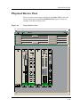
Physical Device View ........................................................................................................2-41
Chapter 3
Configuration Views
What Is in This Chapter .....................................................................................................3-1
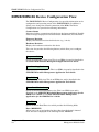
EMME/EMM-E6 Device Configuration View ....................................................................3-2
Interface Configuration Table ......................................................................................3-3
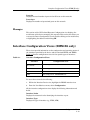
Chassis Configuration View (EMME only) ........................................................................3-3
Module and Port Configuration Views ...............................................................................3-4
Module Management (Module Configuration View Only)..........................................3-5
Port Management (Port Configuration View Only) ....................................................3-5
Trap Configuration .......................................................................................................3-6
Alarm Configuration.....................................................................................................3-6
Error Source..................................................................................................................3-8
Repeater Configuration View .............................................................................................3-8
Repeater Management .................................................................................................3-9
Source Address Management.......................................................................................3-9
Trap Configuration .....................................................................................................3-10
Alarm Configuration...................................................................................................3-10
Error Source................................................................................................................3-11
Board Map...................................................................................................................3-12
Manages ......................................................................................................................3-12
CSI Isolated Repeater Configuration View......................................................................3-12
Repeater Management ...............................................................................................3-12
Manages ......................................................................................................................3-13
Interface Configuration Views (EMM-E6 only) ...............................................................3-13
Port Configuration View (for FDDI) .................................................................................3-14
SMT Device Configuration View ......................................................................................3-16
Station Configuration View........................................................................................3-16
SMT Information ........................................................................................................3-18
ATM Client Application Configuration View...................................................................3-19
Chapter 4
Event and Alarm Messages
What Is in This Chapter .....................................................................................................4-1
Device Events and Alarms..................................................................................................4-1
iv
EMME/EMM-E6
Management Module Guide
Chapter 5
Application View
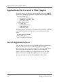
What Is in This Chapter..................................................................................................... 5-1
Applications Not Covered in This Chapter ....................................................................... 5-2
Device Application View ..................................................................................................... 5-2
Network (A, B, or C) Application........................................................................................ 5-5
Isolated Repeater Application............................................................................................ 5-6
Creating an Isolated Repeater .................................................................................... 5-7
DownLoad Application ....................................................................................................... 5-8
ATM Client Application...................................................................................................... 5-8
ATM Client Application Virtual Channel Link View ................................................. 5-9
FddiSMT Application ....................................................................................................... 5-13
Index
9031111 E7
v
vi
EMME/EMM-E6
Management Module Guide
Figures
Chapter 1
Figure 1-1.
Figure 1-2.
Figure 1-3.
Figure 1-4.
Figure 1-5.
Figure 1-6.
Chapter 2
Figure 2-1.
Figure 2-2.
Figure 2-3.
Figure 2-4.
Figure 2-5.
Figure 2-6.
Figure 2-7.
Figure 2-8.
Figure 2-9.
Chapter 3
Figure 3-1.
Chapter 5
Figure 5-1.
Figure 5-2.
Introduction
Example of an EMME Model Configuration ....................................................... 1-4
Using Double-Click Zones to Access SPECTRUM Views ................................... 1-5
Using the Icon Subviews Menu to Access SPECTRUM Views .......................... 1-6
Accessing Device-Specific Subviews .................................................................... 1-7
SPECTRUM Views Roadmap .............................................................................. 1-8
SPMA Applications View ...................................................................................... 1-9
Device Views
Chassis Device View ............................................................................................. 2-3
EMME Module Icon .............................................................................................. 2-5
EMM-E6 Module Icon ........................................................................................... 2-6
MIM Icon ............................................................................................................. 2-20
TPXMIM Icon ...................................................................................................... 2-26
EMME/EMM-E6 Interface Device View ............................................................ 2-31
Interface Icon ...................................................................................................... 2-32
Gauge Control Panel ........................................................................................... 2-38
Physical Device View .......................................................................................... 2-41
Configuration Views
Link Error Rate Estimate .................................................................................. 3-15
Application View
Device Application View Icon Mode) .................................................................... 5-3
Device Application View (List Mode) ................................................................... 5-4
9031111 E7
vii
viii
EMME/EMM-E6
Management Module Guide
Tables
Chapter 2
Table 2-1.
Table 2-2.
Table 2-3.
Table 2-4.
Table 2-5.
Table 2-6.
Table 2-7.
Table 2-8.
Table 2-9.
Table 2-10.
Table 2-11.
Table 2-12.
Table 2-13.
Table 2-14.
Table 2-15.
Table 2-16.
Table 2-17.
Table 2-18.
Table 2-19.
Table 2-20.
Table 2-21.
Table 2-22.
Table 2-23.
Chapter 3
Table 3-1.
Table 3-2.
Table 3-3.
Chapter 4
Table 4-1.
Chapter 5
Table 5-1.
Table 5-2.
Device Views
EMME/EMM-E6 Module Icon Subviews Menu ................................................... 2-7
Bridge Menu Selections......................................................................................... 2-8
Interface Status for the Bridging Application ..................................................... 2-9
Interface Status for the Physical or MIB II Application ................................... 2-10
AUI Port Subviews Menu.................................................................................... 2-10
Repeater Menu Selections................................................................................... 2-11
Repeater Port Channel Label & Background Colors......................................... 2-15
FDDI Label Icon Subviews Menu ....................................................................... 2-16
ATM Label Icon Subviews Menu ........................................................................ 2-17
BRIM Port Label Subviews Menu ...................................................................... 2-18
BRIM Port Status Descriptions .......................................................................... 2-18
MIM Icon Subviews Menu .................................................................................. 2-21
MIM Module Icon Subviews (Repeater option).................................................. 2-22
Repeater Port Icon Subviews Menu ................................................................... 2-23
TPXMIM Icon Subviews Menu ........................................................................... 2-27
TPXMIM Icon Subviews Menu (Module Segment Details option) ................... 2-28
TPXMIM Port Icon Subviews Menu ................................................................... 2-28
Interface Icon Subviews Menu............................................................................ 2-33
Administrative Status for the Physical or MIB II Application ......................... 2-34
Administrative Status for the Bridging Application ......................................... 2-34
Interface Types .................................................................................................... 2-34
Rates Gauge Mode: Attributes and Corresponding Colors ............................... 2-39
Totals Gauge Mode: Attributes and Corresponding Colors .............................. 2-39
Configuration Views
Interface Configuration Views ............................................................................ 3-13
FDDI Ring States ................................................................................................ 3-16
SMT MAC Configurations................................................................................... 3-17
Event and Alarm Messages
EMME/EMM-E6 Events and Alarms ................................................................... 4-1
Application View
Network (A, B, or C) Application Subviews Menu............................................... 5-5
Network (A, B, or C) Application Subviews Menu (Performance Option).......... 5-6
9031111 E7
ix
Table 5-3.
Table 5-4.
Table 5-5.
Table 5-6.
Table 5-7.
x
Isolated Repeater Application Subviews Menu....................................................5-6
Download Application Subviews Menu.................................................................5-8
ATM Client Application Subviews Menu .............................................................5-8
ATM Client Application Subviews Menu (Interfaces option) ..............................5-9
FddiSMT Application Icon Subviews Menu .......................................................5-13
EMME/EMM-E6
Management Module Guide
Preface
Use this guide as a reference for the SPECTRUM EMME/EMM-E6
management software. Before using this guide, you should be familiar with
SPECTRUM’s functions and navigational techniques.
For the purposes of this guide, EMME/EMM-E6 is referred to as “device.”
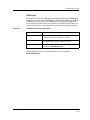
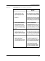
What Is in This Guide
The following outlines the organization of the EMME/EMM-E6
Management Module Guide:
Chapter
Description
Chapter 1
Introduction
Describes the device, the management
module software, and model types.
Chapter 2
Device Views
Describes the Device views representing the
device, connected repeaters, and other views
and information accessed from these views.
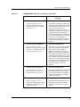
Chapter 3
Configuration Views
Describes the Configuration views for the
device and the network management
information provided by these views.
Chapter 4
Event and Alarm Messages
Lists and explains the event and alarm
messages generated in the Event Log of
Alarm Manager for the device model type.
Chapter 5
Application View
Describes the Application view and
application-specific information within the
Application view for this device.
9031111 E7
xi
Conventions
Conventions
In this manual the following conventions are used.
• Menu selections and buttons referenced in text appear in bold; for
example, Configuration or Detail.
• Buttons’ names appear in shadowed boxes when introducing paragraphs
describing their use; for example,
Detail
• Menu navigation appears in order of selection; for example, Icon
Subviews -> Utilities -> Application.
• Referenced chapter titles and section headings appear in italics.
• Referenced documents appear in bold italics.
• EMME/EMM-E6 is referred to as “device.”
Related SPECTRUM Documentation
It is important when using this guide that you have a clear understanding of
SPECTRUM functionality and navigational techniques as described in the
Administration, Operation, and following documentation:
Report Generator User’s Guide
Getting Started with SPECTRUM 5.0 for Operators
Getting Started with SPECTRUM 5.0 for Administrators
How to Manage Your Network with SPECTRUM
This guide also references the following documents:
SPECTRUM Portable Management Application for the EMME User’s
Guide
SPECTRUM Portable Management Application for the EMM-E6 User’s
Guide
SPECTRUM Portable Management Application Tools Guide
How to Manage Your Network with SPECTRUM
Routing Services Management Module Guide
Preface
xii
EMME/EMM-E6
Management Module Guide
Other Related Documentation
Other Related Documentation
Refer to the following documentation for more information on managing
TCP/IP-based networks:
Martin, James, Kathleen Kavanagh Chapman, Joe Leben. Local Area
Networks: Architectures and Implementations, 2d ed. Englewood Cliffs,
NJ: Prentice Hall, 1994.
Rose, Marshall T. The Simple Book: An Introduction to Management of
TCP/IP-based Internets. Englewood Cliffs, NJ: Prentice Hall, 1991.
Stallings, William. Data and Computer Communications, 4th ed. New
York: Macmillan Publishing Company, 1994.
Tanenbaum, Andrew S. Computer Networks, 3d ed. Englewood Cliffs, NJ:
Prentice Hall, 1996.
9031111 E7
Preface
xiii
Other Related Documentation
Preface
xiv
EMME/EMM-E6
Management Module Guide
Chapter 1
Introduction
What Is in This Chapter
This chapter introduces the SPECTRUM Management Module for the
EMME/EMM-E6. It describes the following:
• EMME/EMM-E6
• SPECTRUM Support
- Modeling Instructions
- Accessing SPECTRUM views from the Device Icon
- Accessing Device-Specific Subviews
• SPECTRUM Views Roadmap
• SPMA Support
9031111 E7
1-1
EMME/EMM-E6
EMME/EMM-E6
The EMME (Ethernet Management Module for Ethernet) and EMM-E6
(Ethernet Management Module for Ethernet with six ports) are multi-port
intelligent bridging modules installed in the right most slot of an MMAC FNB
chassis. They have channels which act as bridge ports (Channels A, B, C, D, E,
and F). Channels A, B, and C also act as repeater ports and direct traffic over
the MMAC Flexible Network Bus (or backplane). Additionally, Cabletron
Systems FDDI modules for the MMAC FNB provide Ethernet to Fiber
Distributed Data Interface (FDDI) bridging capabilities.
With the addition of Repeater Management Control module (RMIM)in the
chassis, the EMME and EMM-E6 function as bridges between up to three
Ethernet 802.3 subnetworks and an Ethernet backbone (fourth) network. The
Repeater MIMs use and control Channels B and C. Other modules use
Channel A and are controlled by the EMME or EMM-E6. Channels D1 and D2
are the AUI ports on the EMME and EMM-E6, and direct traffic to one of two
external Ethernet Port Interface Modules (EPIMs). One D port is operational
at a time, while the other D port is the redundant port and is in STDBY
(standby) or OFF.
The EMM-E6 allows you to monitor, configure, and bridge/route between
channels A, B, and C on the backplane, a fourth external Ethernet via an
EPIM, and two BRIM ports. Optional BRIMs perform the same bridging
functions as EPIMs; they transfer packets between different channels.
However, unlike EPIMs, BRIMs bridge these packets from one technology to
another (e.g., Ethernet to FDDI network backbones, Asynchronous Transfer
Mode [ATM] to Wide Area, etc.). These BRIMs occupy the E and F channels.
The following BRIMs may be installed:
• BRIM-E6: Ethernet interface
• BRIM-W6: WAN interface (not supported at this time)
• BRIM-A6: ATM interface
• BRIM-F6: FDDI interface
Introduction
1-2
EMME/EMM-E6
Management Module Guide
SPECTRUM Support
SPECTRUM Support
The following model type names refer to the models used to specify attributes,
actions, and associations for the EMME and EMM-E6 devices in SPECTRUM:
• HubCSIEMME (EMME)
• BRtrCSIEMM_E6 (EMM-E6)
Standard RMON (RMONApp) DLM (DLM_Agent) and Routing Services
(CtRouter) are also supported and may be purchased separately.
Modeling Instructions
It is recommended that you model all devices in SPECTRUM using the
AutoDiscovery. However, if you wish to model your device manually, follow the
steps below.
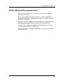
1. Model an EMME/EMM-E6. (Refer to How to Manage Your Network
with SPECTRUM for basic modeling instructions.)
2. Access the EMME/EMM-E6 Device Topology view to determine how many
repeater ports are being used on the backplane of this device.
3. For each repeater connection (Network A, B, or C) shown in the Device
Topology view, model a separate LAN icon (LAN_802_3) on the same
hierarchical level as the EMME/EMM-E6 device icon. (The names of the
LANs should correspond with the names of repeater ports they will be
connected to.)
4. Within the EMME/EMM-E6 Device Topology (DevTop) view, select File ->
Edit to enter the edit mode.
5. Highlight a single repeater icon.
6. Select Edit -> Copy.
7. Click OK in the confirmation window to override the buffer.
8. Open the LAN model created in step 3 with name that corresponds with
the name of the repeater you copied in the previous step.
9. Enter the edit mode by selecting File -> Edit.
10. Select Edit -> Paste to paste the repeater icon into the LAN.
11. Select File -> Save and Close to complete the pasting process. The
off-page EMME/EMM-E6 icon (in shape of the triangle) should appear,
signifying the connection between the repeater and the EMME/EMM-E6
backplane.
9031111 E7
Introduction
1-3
SPECTRUM Support
Accessing SPECTRUM Views from the Device Icon
Repeat the same actions for each repeater icon found in the Device Topology
view of the EMME/EMM-E6. The connections established will appear in the
topology view where EMME/EMM-E6 and network LAN icons were originally
modeled, as well as in the EMME/EMM-E6 Device Topology (Dev Top) view.
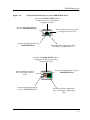
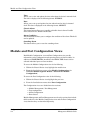
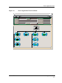
Figure 1-1 shows an example of the EMME model configuration that includes
three channels connected to three repeaters. The EMM-E6 may have
additional BRIM channel connections, which are not shown in this example.
Figure 1-1.
Example of an EMME Model Configuration
Model Name
LAN 802.3
Channel A
Model Name
EMM-E6
EMME/EMM-E6
Model Name
Model Name
LAN 802.3
LAN 802.3
Channel B
Channel C
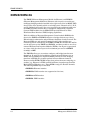
Accessing SPECTRUM Views from the Device Icon
The Device icon provides access to SPECTRUM views that display
device-specific information. Access these views through double-click zones
(Figure 1-2) or the Icon Subviews menus (Figure 1-3). Placing your cursor over
a double-click zone lets you see the name of the view accessed by
double-clicking that zone.
To access the Icon Subviews menu, as shown in Figure 1-4, do the following:
1. Highlight the icon.
2. From the View menu select Icon Subviews or click the applicable mouse
button (middle or right). Refer to Getting Started with SPECTRUM for
Operator’s for information on configuring your mouse.
Introduction
1-4
EMME/EMM-E6
Management Module Guide
SPECTRUM Support
Accessing SPECTRUM Views from the Device Icon
Figure 1-2.
Using Double-Click Zones to Access SPECTRUM Views
Accesses the EMME/EMM-E6 Device
Configuration View; see Chapter 3,
Configuration View.
Accesses the Device Topology
view; see SPECTRUM Views.
Model Name
Accesses the Chassis Device View;
see Chapter 2, Device Views.
HubCSIEMME
Accesses the Performance view;
SPECTRUM Views.
Accesses the Device Application View;
see Chapter 5, Application View.
Accesses the EMME/EMM-E6 Device
Configuration View; see Chapter 3,
Configuration Views.
Accesses theChassis Device
View; see Chapter 2, Device
Views.
Model Name
Accesses the Performance view; see
SPECTRUM Views.
HubCSIEMME
Accesses the Device Topology
view; see SPECTRUM Views.
9031111 E7
Accesses the Device Application
View; see Chapter 5, Application
View.
Introduction
1-5
SPECTRUM Support
Accessing Device-Specific Subviews
Figure 1-3.
Using the Icon Subviews Menu to Access SPECTRUM Views
Model Name
EMM-E6
View
Go Back
Ctrl+b
Go Up
Icon Subviews
View Path
New View
Bookmarks
View History
Current View Info...
Notes...
Jump by name...
Map Hierarchy
Zoom
Page
Close
Ctrl+c
Navigate
Alarms
Performance
Notes...
Utilities
Zoom
Device
Chassis
DevTop
Interface
Physical
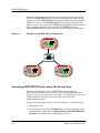
Accessing Device-Specific Subviews
Icon Subviews menus provide access to views that display device-specific
information. Figure 1-4 shows an example of an Icon Subviews menu for an
Application label on the Chassis Module icon located in the Chassis Device
view. The device-specific Icon Subviews menu selections are described under
the applicable section within this guide. The menu selections that are common
to all devices are described in SPECTRUM Menus.
To access the Icon Subviews menu using the View menu, do the following:
1. Highlight the icon.
2. From the View menu, select Icon Subviews.
To access the Icon Subviews menu using the mouse button, do the following:
1. Position the mouse pointer on the icon.
2. Click the applicable mouse button (middle or right). Refer to Getting
Started with SPECTRUM for Operator’s for information on
configuring your mouse.
Introduction
1-6
EMME/EMM-E6
Management Module Guide
SPECTRUM Views Roadmap
Figure 1-4.
Accessing Device-Specific Subviews
1
EMME
Bridging
A
FWD
B
FWD
C
FWD
Close
Ctrl +c
Navigate
Alarms
Performance
Notes...
Utilities
Zoom
Bridge Performance
Bridge Model Information
Special Database
Spanning Tree Information
Static Database Table
Transparent Bridge Info
Common
Device-Specific
SPECTRUM Views Roadmap
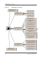
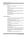
Figure 1-5 shows a “roadmap” of the SPECTRUM views for this device. These
views are accessible from double-click zones (Figure 1-2) and Icon Subviews
menus (Figure 1-3 and Figure 1-4).
9031111 E7
Introduction
1-7
SPECTRUM Views Roadmap
Figure 1-5.
SPECTRUM Views Roadmap
Performance View; refer to
SPECTRUM Views.
Device Views; see
Chapter 2, Device Views.
Chassis Device View
Interface Device View
Physical Device View
EMME/EMM-E6 Device
Configuration View
Chassis Configuration View
(EMME only)
Module Configuration View
Port Configuration View
Model Name
EMM-E6
Repeater Configuration View
Configuration Views; see
Chapter 3, Configuration
Views.
CSI Isolated Repeater
Configuration View
Interface Configuration Views
(EMM-E6 only)
Port Configuration View (for FDDI)
SMT Device Configuration View
ATM Client Application
Configuration View
Network (A, B, or C) Application
DownLoad Application
Application View; see
Chapter 5, Application
View.
Isolated Repeater Application
ATM Client Application
DevTop View; refer to
SPECTRUM Views..
Introduction
1-8
FddiSMT Application
EMME/EMM-E6
Management Module Guide
SPMA Support
SPMA Support
SPECTRUM also supports SPECTRUM Portable Management Application
(SPMA) functionality for the EMME/EMM-E6. To open the SPMA
Applications view from any SPECTRUM view, do the following:
1. Highlight the Device icon.
2. From the View menu, select Icon Subviews -> Utilities ->
Applications....
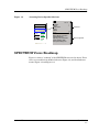
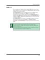
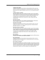
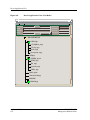
Figure 1-6 shows an example of an SPMA Applications view.
Figure 1-6.
SPMA Applications View
Applications
132.177.118.24 of type BRtrCSIEMME_E6
Community Names
Hub View
Front Panel Redundancy
Redundancy
Port Source Address
CtRouter of type CTRouterApp
Basic Configuration
Bridging of type CSIBridge
Basic Alarms
Bridge View
Network A of type CSIRptr
Alarm Configuration
Link/Seg Traps
Source Addressing
Security Configuration
Redundancy
Port Source Address
Network C of type CSIRptr
Alarm Configuration
Link/Seg Traps
Source Addressing
Security Configuration
Download App of type CmDownLoadApp
TFTP Download
Close
9031111 E7
Introduction
1-9
SPMA Support
The buttons within the SPMA Applications view provide access to
SPMA-specific views and dialog boxes. The Application view for a particular
device may include different buttons depending upon the applications
available, the BRIMs installed, and the configuration of your device. Refer to
the following documentation for information on the SPMA views accessible
from the Applications view:
SPECTRUM Portable Management Application for the EMME User’s
Guide
SPECTRUM Portable Management Application for the EMM-E6 User’s
Guide
SPECTRUM Portable Management Application Tools Guide
Introduction
1-10
EMME/EMM-E6
Management Module Guide
Chapter 2
Device Views
What Is in This Chapter
This chapter describes the following Device views available for the
EMME/EMM-E6:
• Chassis Device view
• Interface Device view
• Physical Device view
See Chapter 1, Introduction, for information on Accessing SPECTRUM Views
from the Device Icon and Accessing Device-Specific Subviews
Each Device view provides a representation of the EMME/EMM-E6’s
configuration and menu access to the views that monitor and control the
EMME/EMM-E6, its modules, and the module’s ports. If the configuration
changes (e.g., a board is pulled from or added to the MMAC), the
corresponding change(s) is displayed.
NOTE
Only the port or application status is updated every polling cycle. Board or
application icons change when a model reconfiguration occurs.
9031111 E7
2-1
Chassis Device View
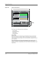
Chassis Device View
This view is a logical representation of the MMAC FNB chassis and the
modules it contains. The Chassis Device view provides both menu access and
double-click zone access to the views that monitor the modules, interfaces or
ports.
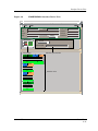
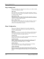
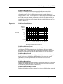
Figure 2-1 shows an example of the Chassis Device view including an EMME
installed in slot number one and Management Interface modules (MIMs) it
manages. MIMs are connected to the EMME via the Chassis FNB Backplane.
Device Views
2-2
EMME/EMM-E6
Management Module Guide
Chassis Device View
Figure 2-1.
Chassis Device View
Primary Landscape 0x00400000 - VNM Host - EMME of type CSIEMME
*
File
View
Help?
Net Addr
Model Name
Sys Up Time
Contact
Manufacturer
Description
Device Type
Location
Prime-App
5 Iso ReptrB
TPXMIM22
4
1 LNK
0
Bridging
2 LNK
0
3 LNK
0
4 LNK
0
5 LNK
0
LNK
6 SEG
0
7 LNK
0
8 LNK
0
9 LNK
0
10 LNK
0
11 LNK
0
12 LNK
0
13 LNK
0
14 LNK
0
15 LNK
0
16 LNK
0
17 LNK
0
18 LNK
0
19 LNK
0
0
20 LNK
0
21 LNK
22 LNK
0
1
2 SEG
3 SEG
4 SEG
5 SEG
6 SEG
7 SEG
8 SEG
9 SEG
9031111 E7
Network A
TPT
SEG
10 SEG
11 SEG
12 SEG
3
Network A
10BT-24
1 LNK
0
0
2 LNK
0
0
3 LNK
0
0
4 LNK
0
LNK
5
0
0
LNK
6 SEG
0
0
0
7 LNK
0
8 LNK
0
LNK
LNK
9
Pkts
0 0
0 10
10 LNK
0
0 11 11 LNK
0
0
12 LNK
0
LNK
13
0
0
14 LNK
0
0
15 LNK
0
0
16 LNK
0
17 LNK
0
18 LNK
0
19 LNK
0
20 LNK
0
21 LNK
0
22 LNK
0
Serial Number
2
1
Network B
TPR-20
1 LNK 0
2 LNK 0
3 LNK 0
4 LNK 0
5 LNK 0
6 LNK 0
7 LNK 0
8 LNK 0
9 LNK 0
10 LNK 0
EMME
Bridging
AA
FWD
B
FWD
C
FWD
D1
FWD
D2
OFF
Repeaters
A
UNLOCKED
B
UNLOCKED
Device Views
2-3
Chassis Device View
EMME/EMM-E6 Module Icon
EMME/EMM-E6 Module Icon
This icon is a logical representation of the physical module, its location in the
MMAC FNB chassis and its front and back panel interfaces or ports.
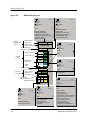
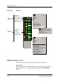
Figure 2-2 shows an example of an EMME module and Figure 2-3 shows an
example of an EMM-E6 module as seen in the Chassis Device View.
NOTES
The callouts in the illustrations that follow identify the labels and, when
applicable, the views to which they provide double-click access. Example: Slot
Number/Notes View - displays the slot number and provides double-click
access to the Notes view.
The menus displayed in these illustrations are the icon subviews menus for
the corresponding labels or the Chassis Module icon.
Device Views
2-4
EMME/EMM-E6
Management Module Guide
Chassis Device View
EMME/EMM-E6 Module Icon
Figure 2-2.
EMME Module Icon
Module
Identification
Labels
Slot Number/
Notes View
1
Model Type/
Model Info. View
EMME
Application Label/
Performance View
Bridging
Interface
Channel
EPIM Ports/
Notes View
FWD
B
FWD
C
FWD
D1
FWD
D2
OFF
Repeaters
Repeater Label
Repeater
Port Labels
Port Channel/
Rptr. Config View
Port Status/
Performance View
Close
Ctrl +c
Navigate
Alarms
Performance
Notes...
Utilities
Zoom
Module Notes
EMME Application
EMME Configuration
EMME Model Information
EMME Front Panel Redundancy
Chassis Configuration
Application Display
Gauge Control Panel
9031111 E7
AA
Interface Status
Interface
Labels
Close
Ctrl +c
Navigate
Alarms
Performance
Notes...
Utilities
Zoom
Bridge Performance
Bridge Model Information
Spanning Tree Information
Static Database Table
Transparent Bridge Info
A
UNLOCKED
B
UNLOCKED
Physical
Bridging
Close
Navigate
Alarms
Performance
Notes...
Utilities
Zoom
Configuration
Ctrl +c
Close
Ctrl +c
Navigate
Alarms
Performance
Notes...
Utilities
Zoom
Redund Configuration
Configuration
Close
Ctrl +c
Navigate
Alarms
Performance
Notes...
Utilities
Zoom
Repeater Notes
Repeater Events
Repeater Alarms
Repeater Performance
Repeater Frame & Error Breakdown
Repeater Frame Size & Protocols
Repeater Configuration
Repeater Model Information
Repeater Redundancy
Repeater Source Address
Repeater Security Configuration
Device Views
2-5
Chassis Device View
EMME/EMM-E6 Module Icon
Figure 2-3.
EMM-E6 Module Icon
Close
Ctrl +c
Navigate
Alarms
Performance
Notes...
Utilities
Zoom
Module Notes
EMM-E6 Application
EMM-E6 Configuration
EMM-E6 Model Information
EMM-E6 Front Panel Redundancy
Application Display
Gauge Control Panel
Module
Identification
Labels
Slot Number/
Notes View
2
Model Type/
Device Config. View
Application Label/
Performance View
Interface
Labels
Bridging
Interface Status
EPIM Ports/
Notes View
BRIM
Port
Repeater Label
Repeater
Port Label
Port Channel/
Rptr. Config View
Port Status/
Performance View
BRIM Label/
Performance View
BRIM Port Labels
Close
Ctrl +c
Navigate
Alarms
Performance
Notes...
Utilities
Zoom
Port Notes
Enable/Disable Port
Port Configuration View
Device Views
2-6
1
EMM-E6
Interface Channel
AA
FWD
B
FWD
C
FWD
D1
FWD
D2
OFF
E Fddi
FWD
Repeaters
A
Close
Ctrl +c
Navigate
Alarms
Performance
Notes...
Utilities
Zoom
Bridge Performance
Bridge Detail
Bridge Model Information
Spanning Tree Information
Static Database Table
Transparent Bridge Info
UNLOCKED
Close
Navigate
Alarms
Performance
Notes...
Utilities
Zoom
Configuration
Ctrl +c
Close
Ctrl +c
Navigate
Alarms
Performance
Notes...
Utilities
Zoom
Redund Configuration
Configuration
FDDI
1 A
2 B
CON
CON
Close
Ctrl +c
Navigate
Alarms
Performance
Notes...
Utilities
Zoom
FDDI Performance
FDDI Configuration
FDDI Station List
FDDI Model Information
Hub Detail
Close
Ctrl +c
Navigate
Alarms
Performance
Notes...
Utilities
Zoom
Repeater Notes
Repeater Events
Repeater Alarms
Repeater Performance
Repeater Frame & Error Breakdown
Repeater Frame Size & Protocols
Repeater Configuration
Repeater Model Information
Repeater Redundancy
Repeater Source Address
Repeater Security Configuration
EMME/EMM-E6
Management Module Guide
Chassis Device View
EMME/EMM-E6 Module Icon
EMME/EMM-E6 Module Identification Labels
These labels provide the following information (refer to Figure 2-1 and
Figure 2-3):
Slot Number
Displays the number of the MMAC FNB slot that the module is connected to.
Double-click this area to open the Notes view described in SPECTRUM
Views.
Model Type
Identifies the type of module in this MMAC FNB slot (e.g., EMM-E6).
Double-click this area of the EMME to open the Model Information view.
Double-click this area of the EMM-E6 to open the EMME/EMM-E6 Device
Configuration View described in Chapter 3, Configuration Views.
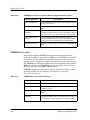
EMME/EMM-E6 Chassis Module Icon Subviews Menu
Table 2-1 lists each of the device-specific Icon Subviews menu selections
available for EMME/EMM-E6. See Chapter 1, Introduction, for information on
Accessing Device-Specific Subviews.
Table 2-1.
EMME/EMM-E6 Module Icon Subviews Menu
Menu Selection
9031111 E7
Description
Module Notes
Opens the Notes view described in SPECTRUM
Views.
EMME/EMM-E6 Application
Opens the Device Application View described in
Chapter 5, Application View.
EMME/EMM-E6 Configuration
Opens the EMME/EMM-E6 Device Configuration
View described in Chapter 3, Configuration Views.
EMME/EMM-E6 Model
Information
Opens the EMME/EMM-E6 Model Information
view described in the SPECTRUM Views.
EMME/EMM-E6 Front Panel
Redundancy
Opens the EMME/EMM-E6 Front Panel
Redundancy view described in the SPECTRUM
Portable Management Application for the
EMME User’s Guide or the SPECTRUM
Portable Management Application for the
EMM-E6 User’s Guide.
Chassis Configuration
(EMME only)
Opens the Chassis Configuration View (EMME
only) described in Chapter 3, Configuration Views.
Application Display
Opens the Application Display submenu, allowing
you to chose the application to be displayed e.g.,
Physical (MIB-II) or Bridging.
Gauge Control Panel
Opens the Gauge Control Panel described in this
chapter.
Device Views
2-7
Chassis Device View
EMME/EMM-E6 Module Icon
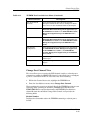
Application Label
Application label provides access to the Icon Subviews menu for the
application displayed (refer to Figure 2-2 and Figure 2-3). Double-click the
Application label to open the Performance view described in SPECTRUM
Views. The application selected determines the information displayed and the
menu selections available. To select the application, highlight the Chassis
Logical Module and select View -> Icon Subviews -> Application Display.
The default application for this view is Bridging.
Table 2-2 describes the Bridging Application Icon Subviews menu selections.
See Chapter 1, Introduction, for information on Accessing Device-Specific
Subviews. There are no specific Icon Subviews menu selections for the
Physical Application.
Table 2-2.
Bridge Menu Selections
Menu Selection
Description
Bridge Performance
Opens the Performance view described in SPECTRUM
Views.
Bridge Detail
(for EMM-E6 only)
Opens the Detail view described in MIB II Applications,
Bridging Applications, and Miscellaneous
Applications.
Bridge Model Information Opens the Model Information view described in
SPECTRUM Views.
Device Views
2-8
Spanning Tree
Information
Opens the Spanning Tree Information view described in
MIB II Applications, Bridging Applications, and
Miscellaneous Applications.
Static Database Table
Opens the Static Database Table view described in MIB
II Applications, Bridging Applications, and
Miscellaneous Applications.
Transparent Bridge Info
Opens the Transparent Bridge Information view, with
Forwarding Database and Port Tables described in MIB
II Applications, Bridging Applications, and
Miscellaneous Applications.
EMME/EMM-E6
Management Module Guide
Chassis Device View
EMME/EMM-E6 Module Icon
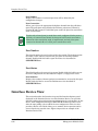
Interface Labels
These labels represent up to six Ethernet Bridging Channels, managed by the
EMME/EMM-E6, that are located on the front panel of the device as well as
within the hub. The Interface labels provide access to the Icon Subviews menu
for the interface and display two information labels: an Interface Channel
label and an Interface Status label.
The menu selection for an Interface Label is Configuration. It opens the
Configuration dialog box, which allows you to enable or disable bridging for
the selected port. See Chapter 1, Introduction, for information on Accessing
Device-Specific Subviews.
Interface Channel
This label identifies one of six channels connected to the EMME/EMM-E6
(refer to Figure 2-2 and Figure 2-3). The A, B, C labels refer to three Ethernet
channels in the MMAC hub, the D1 and D2 labels refer to the redundant
EPIM connection and are described separately in this section. The “E” label
refers to the connection to one of the BRIMs located on the front panel of the
device. In addition, the Interface Channel label for channel “E” provides
information on what kind of BRIM (Ethernet, FDDI, ATM) is attached to this
device.
Interface Status
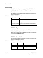
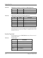
This label indicates the port activity status. Table 2-3 and Table 2-4 list the
possible states relative to the application selected. Refer to the Application
Label, described previously in this chapter, for information on selecting the
application to be displayed.
Table 2-3.
Interface Status for the Bridging Application
Color
9031111 E7
Status
Description
Green
FWD
Bridge port is forwarding network traffic.
Blue
DIS
Port is disabled.
Yellow
LSTN
Bridge is in the listening mode.
Yellow
LRN
Bridge is in the learning mode
Yellow
STBY
Bridge port is in the standby mode.
Yellow
BLK
Bridge port is in the blocking mode.
Red
BRKN
Bridge port is broken.
Blue
UNK
The status is unknown.
Device Views
2-9
Chassis Device View
EMME/EMM-E6 Module Icon
Table 2-4.
Interface Status for the Physical or MIB II Application
Color
Status
Description
Green
ON
Port is operational.
Blue
OFF
Port is disabled.
Yellow
TST
Port is in the test mode.
EPIM Ports
These labels represent the connection to the EPIM ports located on the front
panel of the device, which direct traffic to one of two external Ethernet Port
Interface Modules (EPIMs). One D port is operational (FWD) while the other
D port is redundant (STBY) or inactive (OFF). See Table 2-3 for interface
status label descriptions.
Table 2-5 lists the Subviews menu selections available from this label. See
Chapter 1, Introduction, for information on Accessing Device-Specific
Subviews.
Table 2-5.
AUI Port Subviews Menu
Menu Selection
Description
Redund Configuration
Opens the Front Panel Redundancy view described in the
SPECTRUM Portable Management Application for
the EMME User’s Guide or the SPECTRUM Portable
Management Application for the EMM-E6 User’s
Guide.
Configuration
Opens the Configuration dialog box, which allows you to
enable or disable bridging for the selected port.
BRIM Port
This label represent the connection to one of two BRIM ports located on the
front panel of the EMME/EMM-E6, which direct traffic to the optional
external Bridge/Router Interface Module (BRIM). A second interface provided
by the other BRIM port (forming channel F) will be implemented in the future.
Device Views
2-10
EMME/EMM-E6
Management Module Guide
Chassis Device View
EMME/EMM-E6 Module Icon
Repeater Label
This label represents the Repeater application that allows for transfer of
information between the repeaters in the MMAC chassis and
EMME/EMM-E6. The repeater label provides access to the Icon Subviews
menu for this application. Table 2-6 lists specific Subviews menu selections for
the Repeater Label. See Chapter 1, Introduction, for information on Accessing
Device-Specific Subviews.
Table 2-6.
Repeater Menu Selections
Menu Selection
Description
Repeater Notes
Opens the Notes view described in SPECTRUM Views.
Repeater Events
Opens the Event Log window described in SPECTRUM
Views.
Repeater Alarms
Opens the Alarm Manager view described in SPECTRUM
Views.
Repeater Performance
Opens the Performance view described in SPECTRUM
Views.
Repeater Frame & Error Opens the Repeater Frame & Error Breakdown View
Breakdown
described later in this chapter.
9031111 E7
Repeater Frame Size &
Protocols
Opens the Repeater Frame Size & Protocols View described
later in this chapter.
Repeater Configuration
Opens the Repeater Configuration View described in
Chapter 3, Configuration Views.
Repeater Model
Information
Opens the Repeater Model Information view described in
SPECTRUM Views.
Repeater Redundancy
Opens the Repeater Redundancy view described in the
SPECTRUM Portable Management Application for
the EMME User’s Guide or the SPECTRUM Portable
Management Application for the EMM-E6 User’s
Guide.
Repeater Source
Address
Opens the Repeater Source Address view described in the
SPECTRUM Portable Management Application for
the EMME User’s Guide or the SPECTRUM Portable
Management Application for the EMM-E6 User’s
Guide.
Repeater Security
Configuration
Opens the Repeater Security view described in the
SPECTRUM Portable Management Application for
the EMME User’s Guide or the SPECTRUM Portable
Management Application for the EMM-E6 User’s
Guide.
Device Views
2-11
Chassis Device View
Repeater Frame & Error Breakdown View
This view displays statistics for a selected port. To access this view do the
following:
1. Within the Chassis Device view, highlight the Repeater label.
2. From the Icon Subviews menu, select Repeater Frame & Error
Breakdown.
This view is divided into two areas which provide the following separate
performance information:
• Frame Breakdown
• Error Breakdown
Each area includes the pie chart providing a visual representation of the
numerical statistics. In addition, the Repeater Frame and Error Breakdown
view supplies the following presentation modes, affecting the way data is
displayed in this view:
Total
Allows you to display the current statistical information for all items
contributing to the total value.
Delta
Allows you to display the difference between the previously polled values and
the current value of every item contributing to the total
Accum
Allows you to view the accumulated statistical information for all items since
the Accum button was last selected.
Clear
Select this button to restart the counter. The values will continue to
accumulate until clear is selected or another presentation mode is chosen.
NOTE
Selecting Total, Delta or Accum affects the numerical, as well as graphical
representation of every item contributing to the total.
Pie Chart
When Total is selected, the pie chart displays the current statistical
information for all items contributing to the total value. When Delta is
selected, the pie graph is used to compare the difference between the
previously polled value and the current value of all items. When Accum is
chosen, the pie chart provides the statistics for all items accumulated since
the Accum button was selected.
Device Views
2-12
EMME/EMM-E6
Management Module Guide
Chassis Device View
Frame Breakdown
Displays the breakdown of all the frames transmitted and received through
the selected port. The following categories are displayed first as numbers
followed by percentages:
•
•
•
•
Good Frames
Collisions
Errors
Total
For more information on the individual error types refer to How to Manage
Your Network with SPECTRUM.
Error Breakdown
Displays the number of port traffic errors in an error per second format. The
following types of errors are displayed first as numbers followed by
percentages:
•
•
•
•
•
•
Alignment
CRC
Runts
Giants
OOW Colls
Total
For more information on the individual error types refer to How to Manage
Your Network with SPECTRUM.
Repeater Frame Size & Protocols View
This view displays statistics for a selected port. To access this view do the
following:
1. Within the Chassis Device view, highlight the Repeater label.
2. From the Icon Subviews menu, select Repeater Frame & Protocols.
This view is divided into two areas which provide the following separate
performance information:
• Frame Size
• Protocols
Each area includes the pie chart providing a visual representation of the
numerical statistics. In addition, the Repeater Frame Size and Protocols view
provides the following presentation modes, affecting the way data is displayed
in this view:
9031111 E7
Device Views
2-13
Chassis Device View
Total
Allows you to display the current statistical information for all items
contributing to the total value.
Delta
Allows you to display the difference between the previously polled value and
the current value of every item contributing to the total.
Accum
Allows you to view the accumulated statistical information for all items since
the Accum button was last selected.
Clear
Select this button to restart the counter. The values for all items will continue
to accumulate until clear is selected or another presentation mode is chosen.
NOTE
Selecting Total, Delta, or Accum affects the numerical, as well as graphical
representation of every item contributing to the total.
Pie Chart
When Total is selected, the pie chart displays the current statistical
information for all items contributing to the total value. When Delta is
selected, the pie graph is used to compare the difference between the
previously polled value and the current value of all items. When Accum is
chosen, the pie chart provides the accumulated statistics for all items
accumulated since the Accum button was selected.
Frame Size
Displays a number signifying how many frames from a selected port are of a
certain size. This number is displayed as a numerical value and as percentage
of the total frames transmitted and received. The view provides the following
frame size categories:
• Runts
• 64 -127 Bytes
• 128 - 255 Bytes
• 256 - 511 Bytes
• 512 - 1023 Bytes
• Giants
For more information on the individual error types refer to How to Manage
Your Network with SPECTRUM.
Device Views
2-14
EMME/EMM-E6
Management Module Guide
Chassis Device View
Protocols
Display a number of particular protocol types generated for a selected port.
The following protocols are displayed first as numbers followed by
percentages:
• IP
• OSI
• DECnet
• XNS
• Novel
• AppleTalk
• Banyan
• Ctron
• Other
Repeater Port Label
This label represents the bridging channel connecting the EMME/EMM-E6 to
a MIM located in the hub.
Repeater Port Channel
This label identifies one of the bridging channels this repeater is connected to
(refer to Figure 2-2 and Figure 2-3). Letters “A”, “B”, and “C” signify the three
internal bridging channels. The background for the Repeater Port Type label
is color coded to associate the port with its currently selected channel.
Table 2-7 lists the colors assigned to the repeater ports.
Table 2-7.
Repeater Port Channel Label & Background Colors
Repeater Channel
Background Color
Channel A
Light orange
Channel B
Light blue
Channel C
Light violet
Double-click this label to access the Repeater Configuration View described in
Chapter 3, Configuration Views.
9031111 E7
Device Views
2-15
Chassis Device View
Repeater Port Status
This label indicates the port activity status. Double-click the Repeater Port
Status label to access the Performance view described in SPECTRUM Views.
BRIM Label (exclusive to EMM-E6)
This label represents the interface to which EMM-E6 provides bridging or
routing capabilities through the additional BRIM connections on the front
panel of the device. Depending on the BRIMs connected to the device, the
EMM-E6 can supply one additional interface (channel “E”) configured to
provide bridging or routing to Ethernet, FDDI, or ATM networks. An EMM-E6
equipped with an Ethernet BRIM will not display a separate Ethernet label.
FDDI Label
This label represents the FDDI application and signifies that the EMM-E6 is
configured to provide additional bridging or Feeder Node Routing on FDDI.
The FDDI label provides access to the FDDI application-specific Icon
Subviews menu. Table 2-8 describes all menu selections accessible from this
label. See chapter 1, Introduction, for information on Accessing Device-Specific
Subviews.
Table 2-8.
FDDI Label Icon Subviews Menu
Menu Selection
Description
FDDI Performance
Opens the Performance view described in SPECTRUM
Views.
FDDI Configuration
Opens the SMT Device Configuration View described in
Chapter 3, Configuration Views.
FDDI Station List
Opens the FDDI Station view described in MIB II
Applications, Bridging Applications,
andMiscellaneous Applications.
FDDI Model
Information
Opens the SMT Model Information view described in
SPECTRUM Views.
Hub Detail
Opens the FddiSMT Detail view described in MIB II
Applications, Bridging Applications, and
Miscellaneous Applications.
Double-click this label to open the Performance view described in
SPECTRUM Views.
Device Views
2-16
EMME/EMM-E6
Management Module Guide
Chassis Device View
ATM Label
This label represents the ATM application and signifies that the EMM-E6 is
configured to provide additional bridging or Feeder Node Routing on ATM. the
ATM label provides access to the ATM Application specific Icon Subviews
menu. Table 2-9 describes all menu selections accessible from this label. See
chapter 1, Introduction, for information on Accessing Icon-Specific Subviews.
Table 2-9.
ATM Label Icon Subviews Menu
Menu Selection
Description
Configuration
Opens the ATM Client Application Configuration View
described in Chapter 3, Configuration Views.
VCL Table
Opens the ATM Client Application Virtual Channel Link
View described in Chapter 5, Application View.
Model Information
Opens the ATM Application Model Information View
described in SPECTRUM Views.
Double-click this label to open the Performance view described in
SPECTRUM Views.
9031111 E7
Device Views
2-17
Chassis Device View
BRIM Port Label
This label identifies the port on the front panel of the BRIM. BRIMs with a
single front panel port do not display BRIM Port labels (e.g., ATM) therefore
their BRIM Channel represents the entire BRIM connection (refer to
Figure 2-3).
The BRIM Port label provides access to the Icon Subviews Menu described in
Table 2-10. See chapter 1, Introduction, for information on Accessing
Device-Specific Subviews.
Table 2-10.
BRIM Port Label Subviews Menu
Menu Selection
Description
Port Notes
Opens the Notes view described in SPECTRUM Views.
Enable/Disable Port
Opens a dialog box which allows you to enable or disable a
selected port.
Port Configuration View Opens the Port Configuration view described in Chapter 3,
Configuration Views.
BRIM Port Type Label
This label consists of two fields: the number field and the letter field. The
number field displays the number assigned to this BRIM port. The letter field
displays the type of this port.
Double-click the number field of the BRIM Port Type label to access the Notes
view described in SPECTRUM Views.
BRIM Port Status Label
This label indicates the port activity status. All possible states and their color
definitions are described in Table 2-11.
Table 2-11.
BRIM Port Status Descriptions
Color
Device Views
2-18
State
Description
Green
ACT
active
Blue
DIS
disabled
Yellow
CON
connecting
Red
SBY
standby
EMME/EMM-E6
Management Module Guide
Chassis Device View
MIM Icon
MIM Icon
This icon represents a Media Interface Module (MIM). There are two basic
types of MIMs that can be managed by the EMME/EMM-E6: Repeater MIMs
(RMIMs) and non-repeater MIMs.
The EMME/EMM-E6 manages the RMIMs located in the MMAC chassis
through Ethernet channels B, and C. RMIMs can repeat packets
autonomously without channeling them through the EMME/EMM-E6. The
members of the RMIM family designed to work with the EMME/EMM-E6 are:
FORMIM, CXRMIM, TPRMIM, and TPXMIM. Figure 2-4 shows an example
of a Repeater MIM icon.
The EMME/EMME-6 uses channel A on the MMAC backplane to transmit
and receive data from non-repeater MIMs (i.e., TRMIMs, FOMIMs,
THN-MIMs). The EMME/EMM-E6 provides repeater functionality for these
MIMs.
NOTES
The callouts in the illustration below identify the labels and, when applicable,
the view to which they provides double-click access. Example: Slot
Number/Notes View - displays the slot number and provides double-click
access to the Notes view.
The menus displayed in these illustrations are the icon subviews menus for
the corresponding labels or the Chassis Module icon.
9031111 E7
Device Views
2-19
Chassis Device View
MIM Icon
Figure 2-4.
MIM
Identification
Labels
Repeater
Port Label
MIM Icon
Slot Number/
Notes View
Module Channel
or Isolation Station/
Performance View
Module Type/
Module Config. View
Port Number/
Notes View
Port Status/
Port Config. View
Port Statistics/
Performance View
2 Network B
FORMIM-22
1 SEG
2 LNK
3 LNK
4 LNK
5 SEG
6 ON
7 LNK
8 LNK
9 SEG
10 SEG
11 ON
12 SEG
0
0
0
0
0
487
0
0
0
0
147
0
Close
Navigate
Alarms
Performance
Notes...
Utilities
Zoom
Module Notes
Serial Number
Module Configuration
Module Performance
Module Dev Top View
Repeater
Ctrl +c
Module Frame & Error Breakdown
Module Frame Size & Protocols
Enable All Ports
Change Module Channel
Close
Ctrl +c
Navigate
Alarms
Performance
Notes...
Utilities
Zoom
Port Notes
Port Configuration
Port Performance
Port Frame and Error Breakdown
Port Frame Size & Protocols
Port Redundancy
Port Source Address
Port Security Configuration
Enable/Disable Port
MIM Identification Labels
These labels provide the following information (refer to Figure 2-4):
Slot Number
Displays the number of the MMAC FNB slot that the module is connected to.
Double-click this area to open the Notes view described in SPECTRUM
Views.
Device Views
2-20
EMME/EMM-E6
Management Module Guide
Chassis Device View
MIM Icon
Module Channel or Isolation Station
Displays the network/channel that the module is connected to. If the module is
in the stand-alone mode, “StandAlone” is displayed. If more than one channel
is in use by the module, “StandAloneX” or “NetworkX” is displayed.
Double-click this area to access the Performance view described in
SPECTRUM Views.
Module Type
Displays the type of module in this MMAC FNB slot (e.g., FOM-22).
Double-click this area to access the Module Configuration view described in
Chapter 3, Configuration Views.
MIM Icon Subviews Menu
Table 2-12 describes each of the module-specific Icon Subviews menu
selections available for the Repeater module. Table 2-13 describes a submenu
accessible by clicking the Repeater option of the Icon Subviews menu. See
Chapter 1, Introduction, for information on Accessing Device-Specific
Subviews.
Table 2-12.
MIM Icon Subviews Menu
Menu Selection
9031111 E7
Description
Module Notes
Opens the Notes view described in SPECTRUM Views.
Serial Number
Opens the dialog box allowing you to enter or alter the
serial number for the selected module.
Module Configuration
Opens the Module Configuration view described in Chapter
3, Configuration Views.
Module Performance
Opens the Performance view described in SPECTRUM
Views.
Module DevTop View
Opens the Device Topology view described in SPECTRUM
Views.
Repeater
Opens a submenu described in Table 2-13.
Device Views
2-21
Chassis Device View
MIM Icon
Table 2-13.
MIM Module Icon Subviews (Repeater option)
Menu Selection
Description
Module Frame & Error
Breakdown
Opens the Repeater Frame & Error Breakdown View
described earlier in this chapter.
Module Frame Size &
Protocols
Opens the Repeater Frame Size & Protocols View described
earlier in this chapter.
Enable All Ports
Opens a dialog box which allows you to enable or disable all
ports on a selected module.
Change Module Channel Opens the Change Module Channel View (RMIMs only)
(RMIM only)
described later in this chapter.
Change Module Channel View (RMIMs only)
This view allows you to change the FNB channel used by a port to
communicate with the EMME/EMM-E6. It also allows you to reconfigure the
module to a stand-alone mode if it provides its own repeater functionality. To
access this view do the following:
1. Within the Chassis Device view, highlight the Repeater MIM.
2. From the Icon Subviews menu, select Repeater -> Change Module
Channel.
When configured to operate on channels B or C, the Repeater MIM provides
its own repeating; when operating on channel A, its ports depend on the
EMME/EMM-E6 for repeater functionality. Change Module Channel view
provides the following information and fields:
Module Number
Displays the slot number where the selected RMIM is located. The RMIM
located in this slot will be the only one affected by the configuration changes.
Module Connection
Allows you to chose the appropriate backplane channel or mode. The possible
selections are: Channel B, Channel C, Stand_Alone, and Channel_X.
The Stand_Alone option can be applied to all ports configured to use Channels
B or C. Any ports that are configured to operate on Channel A cannot be
switched to the Stand_Alone mode. For more information, see Creating an
Isolated Repeater in Chapter 5, Application View.
Board-level settings will override the any individual port-level settings.
NOTES
Refer to Release Notes that were shipped with your EMME/EMM-E6
firmware for more information about the implication of operating your
TPXMIM in a Stand_Alone mode.
Device Views
2-22
EMME/EMM-E6
Management Module Guide
Chassis Device View
MIM Icon
Repeater Port Labels
These labels represent repeaters located on the front panel of the RMIM
which supply outside chassis network connectivity.
Repeater Port labels provide access to the port-specific Icon Subviews Menu
described in Table 2-14. See Chapter 1, Introduction, for information on
Accessing Device-Specific Subviews.
Table 2-14.
Repeater Port Icon Subviews Menu
Menu Selection
9031111 E7
Description
Port Notes
Opens the Notes view described in SPECTRUM Views.
Port Configuration
Opens the Port Configuration view described in Chapter 3,
Configuration Views.
Port Performance
Opens the Performance view described in SPECTRUM
Views.
Port Frame & Error
Breakdown
Opens the Port Frame & Error Breakdown view. For
description of fields in this view, refer to the Repeater
Frame & Error Breakdown View described earlier in this
chapter.
Port Frame Size &
Protocols
Opens the Port Frame Size & Protocols view. For
description of fields in this view, refer to the Repeater
Frame Size & Protocols View described earlier in this
chapter.
Port Redundancy
Opens the Repeater Redundancy view described in the
SPECTRUM Portable Management Application for
the EMME User’s Guide or the SPECTRUM Portable
Management Application for the EMM-E6 User’s
Guide.
Port Source Address
Opens the Port Source Address view described in the
SPECTRUM Portable Management Application for
the EMME User’s Guide or the SPECTRUM Portable
Management Application for the EMM-E6 User’s
Guide.
Port Security
Configuration
Opens the port Security Configuration view described in the
SPECTRUM Portable Management Application for
the EMME User’s Guide or the SPECTRUM Portable
Management Application for the EMM-E6 User’s
Guide.
Enable/Disable Port
Opens a dialog box which allows you to enable or disable a
selected port.
Device Views
2-23
Chassis Device View
MIM Icon
Port Number
Identifies the port’s location within the module. The background for this label
is color coded to associate the port with its currently selected channel.
Double-click this label to open the Notes view described in SPECTRUM
Views.
Port Status
Describes the port activity status.
Port Statistics
Displays the number of frames (packets) transmitted or received by this port.
Device Views
2-24
EMME/EMM-E6
Management Module Guide
Chassis Device View
TPXMIM
TPXMIM
The EMME/ EMM-E6 also supports Cabletron’s family of Twisted Pair
Switching Media Interface Modules (TPXMIMs). The TPXMIM-20, -22, -33
and -34 are a series of port assignment modules designed specifically for
Cabletron’s MMAC FNB hubs equipped with the EMME/EMM-E6. TPXMIM
permits the entire board (bank switching) or each individual port (the port
assignment) to be assigned to any of the three Ethernet channels A, B, and C
on the MMAC FNB backplane. This way the unnecessary traffic across the
bridge can be eliminated. The TPXMIM gives you an option of reassigning
ports to different channels right at the management station without having to
move the cable.
Figure 2-5 displays the TPXMIM icon as seen in the Chassis Device View.
NOTES
The callouts in the illustration below identify the label and, when applicable,
the view to which they provide double-click access. Example: Port
Number/Notes View - displays the sport number and provides double-click
access to the Notes view.
The menus displayed in these illustrations are the icon subviews menus for
the corresponding labels or the Chassis Module icon.
9031111 E7
Device Views
2-25
Chassis Device View
TPXMIM
Figure 2-5.
TPXMIM Icon
Close
Ctrl +c
Navigate
Alarms
Performance
Notes...
Utilities
Zoom
Module Notes
Serial Number
Enable All Ports
Change Module Channel
Module Segment Details
Slot Number
Module
Identification
Labels
Module Channel
or Isolation Station
Module Type
EPIM Port
Port Number/
Notes View
TPXMIM
Port Labels
Port Status/
Port Config. View
Port Statistics/
Performance View
Device Views
2-26
5 Network B
TPXMIM22
1
2 LNK
3 LNK
4 LNK
5 LNK
6 LNK
7 LNK
8 LNK
9 LNK
10 ON
11 LNK
12 LNK
13 LNK
14 LNK
15 LNK
16 LNK
0
0
0
0
0
0
0
0
0
2
0
0
0
0
0
0
Network A
Network B
Network C
Module Configuration
Module Performance
Module Frame & Error Breakdown
Module Frame Size & Protocols
Module Devtop View
Close
Ctrl +c
Navigate
Alarms
Performance
Notes...
Utilities
Zoom
Port Notes
Port Configuration
Port Performance
Port Frame and Error Breakdown
Port Frame Size & Protocols
Port Redundancy
Port Source Address
Port Security Configuration
Enable/Disable Port
Change Port Channel
EMME/EMM-E6
Management Module Guide
Chassis Device View
TPXMIM
TPXMIM Identification Labels
These labels provide the following information (refer to Figure 2-5):
Slot Number
Displays the number of the MMAC-FNB slot that the module is connected to.
Double-click this area to open the Notes view described in SPECTRUM
Views.
Module Channel or Isolation Station
Displays the channel that the module is connected to. If the module is in the
stand-alone mode, “StandAlone” is displayed. If more than one channel is in
use by the module, “StandAloneX” or “NetworkX” is displayed.
Module Type
Displays the type of module in this MMAC FNB slot (e.g.,TXMIM 22).
TPXMIM Icon Subviews Menu
Table 2-15 describes each of the module-specific Icon Subviews menu
selections available for the TPXMIM. Table 2-16 describes the submenu
accessible for each channel listed under the Module Segment Detail option.
See Chapter 1, Introduction, for information on Accessing Device-Specific
Subviews.
Table 2-15.
TPXMIM Icon Subviews Menu
Menu Selection
Description
Module Notes
Opens the Notes view described in SPECTRUM Views.
Serial Number
Opens a dialog box allowing you to enter or alter the serial
number for the selected module.
Enable All Ports
Opens a dialog box allowing you to enable or disable all
ports located on a selected module.
Change Module Channel Opens the Change Module Channel View (RMIMs only)
(Channel B & C only)
described earlier in this in this chapter.
Module Segment Details Allows you to access a submenu for each channel (A, B, and
C) being used. Table 2-16 lists the menu selections for these
channels.
9031111 E7
Device Views
2-27
Chassis Device View
TPXMIM
Table 2-16.
TPXMIM Icon Subviews Menu (Module Segment Details option)
Menu Selection
Description
Module Configuration
Opens the Module Configuration view described in Chapter
3, Configuration Views.
Module Performance
Opens the Performance view described in SPECTRUM
Views.
Module Frame & Error
Breakdown
Opens the Module Frame & Error Breakdown view. For
description of fields in this view refer to the Repeater Frame
& Error Breakdown View described earlier in this chapter.
Module Frame Size &
Protocols
Opens the Module Frame Size & Protocols view. For
description of fields in this view refer to the Repeater Frame
Size & Protocols View described earlier in this chapter.
Module Devtop View
Opens the Device Topology view described in SPECTRUM
Views.
TPXMIM Port Labels
These labels represent TPXMIM ports situated on the front panel of the
module. Port number 1 represents the EPIM port. If an EPIM is not installed
in the device, the Port label will not display the port status. The function of
repeater ports is to supply the module with connectivity to external networks.
The TPXMIM port management differs from the management of the ordinary
MIM ports because every TPXMIM port can be assigned to any of the three
Ethernet channels on the MMAC FNB backplane.
TPXMIM Port labels provide access to the port-specific Icon Subviews menu
described in Table 2-17. See Chapter 1, Introduction, on Accessing
Device-Specific Subviews.
Table 2-17.
TPXMIM Port Icon Subviews Menu
Menu Selection
Device Views
2-28
Description
Port Notes
Opens the Notes view described in the SPECTRUM Views.
Port Configuration
Opens the Port Configuration view described in Chapter 3,
Configuration Views.
Port Performance
Opens the Performance view described in SPECTRUM
Views.
Port Frame & Error
Breakdown
Opens the Port Frame & Error Breakdown view. For
description of fields in this view, see the Repeater Frame &
Error Breakdown View described earlier in this chapter.
EMME/EMM-E6
Management Module Guide
Chassis Device View
TPXMIM
Table 2-17.
TPXMIM Port Icon Subviews Menu (Continued)
Menu Selection
Description
Port Frame Size &
Protocols
Opens the Port Frame Size & Protocols view. For
description of fields in this view, see the Repeater Frame
Size & Protocols View described earlier in this chapter.
Port Redundancy
Opens the Repeater Redundancy view described in the
SPECTRUM Portable Management Application for
the EMME User’s Guide or the SPECTRUM Portable
Management Application for the EMM-E6 User’s
Guide.
Port Source Address
Opens the Port Source Address view described in the
SPECTRUM Portable Management Application for
the EMME User’s Guide or the SPECTRUM Portable
Management Application for the EMM-E6 User’s
Guide.
Port Security
Configuration
Opens the Port Security Configuration view described in
the SPECTRUM Portable Management Application
for the EMME User’s Guide or the SPECTRUM
Portable Management Application for the EMM-E6
User’s Guide.
Enable/Disable
Opens a dialog box which allows you to enable or disable a
selected port.
Change Port Channel
Opens the Change Port Channel View described later in this
chapter.
Change Port Channel View
This view allows you to reassign the FNB channel used by a selected port to
communicate within the MMAC FNB chassis. It also allows you to reconfigure
a port to a stand-alone mode. To access this view do the following:
1. Within the Chassis Device view, highlight the TPXMIM icon.
2. From the Icon Subviews menu, select Change Port Channel.
When configured to operate on channels B or C, the TPXMIM provides its own
repeating, when operating on channel A, TPXMIM ports depend on the
EMME/EMM-E6 for repeater functionality. All TPXMIM ports default to
channel B when first installed. Change Port Channel view provides the
following fields:
Module Number
Displays the slot number where the TPXMIM containing a selected port is
located.
9031111 E7
Device Views
2-29
Interface Device View
Port Number
Displays the number of a selected port that will be affected by the
configuration changes.
Port Connection
Allows you to chose the appropriate backplane channel from the pull-down
menu. The pull-down menu includes the following selections: Channel A,
Channel B, and Channel C. Individual ports cannot be placed in stand-alone
mode via this menu.
NOTE
To place only selected ports in stand-alone mode, configure all other ports so
that they are connected to Channel A: those ports will remain connected to
Channel A when stand-alone mode is implemented, and only those ports
connected to channels B or C will be put in stand-alone mode.
Port Number
This label identifies the port location within the module. The background for
this label is color coded to associate the port with its currently selected
channel. Double-click this label to open the Notes view described in
SPECTRUM Views.
Port Status
This label describes the port activity status. Double-click this label to access
the Port Configuration view described in Chapter 3, Configuration Views.
Port Statistics
Displays the number of frames (packets) transmitted or received by this port.
Double-click this label to access the Performance view described in
SPECTRUM Views.
Interface Device View
This section describes the Interface icons and the Interface Options panel
displayed in the Interface Device view. The Interface Device view provides
dynamic configuration and performance information for each interface on this
device. If the configuration changes, SPECTRUM modifies the Device view
after the next polling cycle to reflect the new configuration. This view also
provides a Device icon which allows you to monitor device operation and to
access other device-specific views. Figure 2-6 provides an example of the
Interface Device View.
Device Views
2-30
EMME/EMM-E6
Management Module Guide
Interface Device View
Figure 2-6.
EMME/EMM-E6 Interface Device View
EMM-E6 of type HubCSIEMME of Landscape golem: Primary
* File
View
Help?
Model Name
System Up Time
Net Addr
Contact
Manufacturer
Description
Device Type
Primary Application
Location
Bridging
Serial Number
Model Name
Filter
EMM-E6
Physical
Interface Description
Device Icon
ON
A
ETHERNET
Interface Options Panel
OFF
E
ATM
0:0:1D:17:2F:3C
0:0:1D:17:2F:3C
0
0
OFF
B
ETHERNET
0:0:1D:17:2F:3C
0
OFF
C
Interface Icons
ETHERNET
0:0:1D:17:2F:3C
0
ON
D
ETHERNET
0:0:1D:17:2F:3C
0
9031111 E7
Device Views
2-31
Interface Device View
Interface Icons
Interface Icons
These interface icons represent the interfaces and ports of the device. The
icons identify the type of interface or port and provide statistical information.
Figure 2-7 shows an example of an interface icon, its Icon Subviews menu,
and its labels/double-click zones.
NOTES
The callouts (a through f) in the illustration below identify the labels and the
views to which they provide double-click access. Example: Administrative
Status Label/Port Configuration-BRIMIfATM view displays the interface
status and provides double-click access to the Port Configuration-CSIIfPort
view.
The menu displayed in the illustration is the icon subviews menu for that
interface icon.
Figure 2-7.
Interface Icon
(a)
(b)
ON
A
(c)
(d)
ATM
(e)
0:0:1D:17:2F:3C
134.141.56.167
(f)
0
Icon Subviews Menu:
Close
Ctrl +c
Navigate
Alarms
Performance
Notes...
Utilities
Configuration
Secondary Address Panel
Protocols
Model Information
(ATM only)
CtAtProtoApp
CtIpxRipApp
CtIpxSapApp
CtDecProtoApp
Configuration
Performance
a. Interface Label
b. Administrative Status Label/Port Configuration-BRIMIfATM View
c. Interface Type Label
d. MAC Address Label/CSI Interface Port Model Information View
e. Network Address Label/Secondary Address Panel
f.
Device Views
2-32
Gauge Label/Performance - CSIIfPort View
EMME/EMM-E6
Management Module Guide
Interface Device View
Interface Icons
Interface Icon Subviews Menu
Table 2-18 describes each of the device-specific Icon Subviews menu selections
available from the Interface icon. See Chapter 1, Introduction, for information
on Accessing Device-Specific Subviews.
Table 2-18.
Interface Icon Subviews Menu
Menu Selection
Description
Configuration
Opens an Interface Configuration view for the specific
interface type (e.g., Ethernet, FDDI) of the selected
Interface icon. These configuration views are described in
Chapter 3,Configuration Views.
Secondary Address
Panel
Opens the Secondary Address Panel described later in this
chapter.
Protocols
(ATM only)
Allows you to access protocols submenu. The
ATMClientApp menu selection provides access to the ATM
Client Application Configuration View described in Chapter
3, Configuration Views and the Performance view described
in SPECTRUM Views. For other menu selections refer to
the Routing Services Management Module Guide as
applicable.
Model Information
Opens the Model Information view described in
SPECTRUM Views.
Interface Label
This label displays the name of the interface. Letters A, B, and C represent the
FNB/backplane channels. Letter D represents the front panel EPIM
connection, and the letter E represents EMM-E6’s BRIM interface.
Administrative Status Label
This label displays the status of this interface. The default application for this
view is Bridging. Table 2-19 and Table 2-20 list all possible states and their
corresponding colors for Physical and Bridging Application. To select the
application to be displayed (Physical, Bridging) click the Filter button in the
Interface Options Panel. See the Interface Options panel description later on
in this chapter for more information on the Filter button.
9031111 E7
Device Views
2-33
Interface Device View
Interface Icons
Table 2-19.
Administrative Status for the Physical or MIB II Application
Color
Table 2-20.
Status
Description
Green
ON
Port is operational.
Blue
OFF
Port is off.
Yellow
TST
Port is in the test mode.
Administrative Status for the Bridging Application
Color
Status
Description
Green
FWD
Bridge port is forwarding.
Blue
DIS
Port is disabled.
Magenta
LST
Bridge is in the listening mode.
Magenta
LRN
Bridge is in the learning mode.
Orange
BLK
Bridge port is in the blocking mode.
Red
BRK
Bridge port is broken.
Blue
The status is unknown.
Double-click this label to access the configuration view specific to the interface
type of the Interface icon selected. See Chapter 3, Configuration Views, for the
description of this view.
Interface Type Label
This label displays the type of EMME/EMM-E6 interface. Table 2-21 lists all
possible interface types.
Table 2-21.
Interface Types
Interface Type
Device Views
2-34
Description
Other
None of the following
Reg1822
Regular 1822
HDH1822
HDLC Distant Host protocol
DDNX25
Defense Data Network X.25
rfc877X25
RFC877 X.25
Ethernet
Ethernet CSMA/CD
iso88023
ISO CSMA/CD
EMME/EMM-E6
Management Module Guide
Interface Device View
Interface Icons
Table 2-21.
Interface Types (Continued)
Interface Type
9031111 E7
Description
iso88024
ISO token bus
iso88025
ISO token ring
iso88026
ISO man
starLan
StarLAN IEEE 802.3
Prot10MB
ProNET 10 Mbps
Prot80MB
ProNET 80 Mbps
HyChan
Hyperchannel
FDDI
Fiber Distributed Data Interface
LAPB
X.25 Line Access Procedure, Balanced
SDLC
IBM Synchronous Data Link Control protocol
T1
T1 link (USA and Japan)
CEPT
T1 link (Europe)
BasicISDN
Basic Integrated Services Digital Network
PrimISDN
Proprietary Integrated Services Digital Network
PPSerial
Proprietary Point to Point Serial
PPP
Point to Point Protocol
SFTWARLPBK
Software Loopback
CLNPoverIP
Connectionless Network Protocol over IP
Enet3MB
Ethernet 3 Mbps
XNSoverIP
Xerox Network Service Protocol over IP
SLIP
Generic Serial Line IP
ULTRA
ULTRA Technologies
T-3
T3 link
SMDS
Switched Multimegabit Data Service
FrameRelay
T1 Frame relay
ATM
Asynchronous Transfer Mode
Device Views
2-35
Interface Device View
MAC Address Label
This label displays the MAC address of the EMME/EMM-E6 interface.
Double-click this label to open the CSI Interface Port Model Information view
described in SPECTRUM Views.
Network Address Label
This label displays the current IP address of the interface. To select a different
IP address for this interface, do the following:
1. Double-click the Network Address label to open the Secondary Address
panel.
2. From the Address/Mask table, select the desired IP address entry to
replace the correct IP address.
3. Click Update.
Secondary Address Panel
This panel allows you to view and change the current IP Address and Mask for
this device. The Secondary Address Panel includes a table with different IP
Addresses and Masks. Information displayed in this table is obtained from the
Address Translation table within the device’s firmware. The Secondary
Address Panel provides the following fields and buttons:
IP Address
Displays the current IP address for this interface.
Update
This button allows you to save changes made to the current IP address of the
interface.
See Network Address Label for instructions on how to change the current IP
address for the selected interface.
Gauge Label
This label displays the performance statistic determined by the Gauge Control
Panel for this interface. (Refer to the Gauge Control Panel later in this chapter
for more information.) Double-click on this label to open the
Performance-CSIIfPort view described in SPECTRUM Views.
Device Views
2-36
EMME/EMM-E6
Management Module Guide
Interface Device View
Interface Options Panel
Interface Options Panel
This area of the Interface Device view allows you to modify the presentation of
a highlighted Logical Interface icon. Double-click a non-text area of this panel
to open the Gauge Control Panel, described later in this section. The Interface
Options panel provides the following information:
Filter
This menu button allows you to select the application to be displayed by the
interface icons. You can leave the application currently running or you can
select other applications such as IP routing if the SPECTRUM Routing
Services Management Module is loaded. For more information, refer to the
Routing Services Management Module Guide.
Interface Description
This field provides a description of the highlighted interface. If no interface is
highlighted, this field is empty.
Gauge Control Panel
This panel (Figure 2-8) allows you to change the type of statistical information
displayed on the Gauge label of the Interface icon. To access the Gauge
Control Panel, either double-click the background of the Interface Options
panel, or do the following:
1. Within the Interface Device view, highlight the Interface Options panel.
2. From the Icon Subviews menu, select Gauge Control Panel.
or
1. Within the Chassis Device view, highlight the EMME/EMM-E6 module
icon.
2. From the Icon Subviews Menu, select Gauge Control Panel.
9031111 E7
Device Views
2-37
Interface Device View
Gauge Control Panel
Figure 2-8.
Gauge Control Panel
Gauge Control Panel
Gauge Mode
Rates
Totals
Percentages
Gauge Type
Numeric
Linear
Selected Attribute
Load
Load In
Load Out
Packet Rate
In Packet Rate
Out Packet Rate
% Discard
% Filtered
Apply
Keep Settings
Reset
Close
Gauge
Buttons
Default
The Gauge Control Panel provides the following:
•
•
•
•
Gauge Mode
Selected Attribute
Gauge Type
Gauge Buttons
Gauge Mode
This area allows you to select the type of information shown on the Gauge
Label of the interface icon: Rates, Totals, or Percentages. The Percentages
selection displays the percentage of the selected interface compared to the rest
of the interfaces.
The color displayed on the Gauge Label depends on the particular mode and
statistical attribute selected. Table 2-22 and Table 2-23 provide a list of
attributes and their corresponding colors for the Totals mode and Rates mode
respectively.
Device Views
2-38
EMME/EMM-E6
Management Module Guide
Interface Device View
Gauge Control Panel
Table 2-22.
Rates Gauge Mode: Attributes and Corresponding Colors
Selected Attribute
Table 2-23.
Color
Load
Green
Load In
Green
Load Out
Green
Packet Rate
Blue
In Packet Rate
Blue
Out Packet Rate
Blue
% Discard
Tan
% Filtered
Gray
% Forwarded
Violet
% Host Bound
Yellow
% Error
Orange
% Transmitted
White
Totals Gauge Mode: Attributes and Corresponding Colors
Selected
Attribute
Color
Errors
Orange
In Packets
Blue
Out Packets
Blue
In Octets
Green
Out Octets
Green
Discards
Tan
Forwarded
Purple
Host Bound
Yellow
Transmitted
White
Filtered
Gray
Selected Attribute
This area allows you to select the statistical attribute displayed on the
Interface icon’s Gauge label. The label changes color to reflect the attribute
selected.
9031111 E7
Device Views
2-39
Interface Device View
Gauge Type
This area allows you to select either a numeric or linear display on the Gauge
label.
Gauge Buttons
The following describes the Gauge buttons:
Apply
Applies the current settings to the Gauge label temporarily, but does not save
the settings.
Reset
Returns the settings to the previously saved values.
Keep Settings
Saves the current settings while SpectroGRAPH is running. Settings return to
the default while you restart SpectroGRAPH.
Close
Closes the Gauge Control Panel.
Default
Returns the settings to the SPECTRUM default.
Device Views
2-40
EMME/EMM-E6
Management Module Guide
Physical Device View
Physical Device View
This view shows a static image of all slots in the MMAC FNB Chassis and
devices placed in them, including EMME/EMM-E6. Figure 2-9 shows an
example of the Physical Device view.
Figure 2-9.
Physical Device View
EMME of type HubCSIEMME of Landscape castle: Primary
*
File
View
Options
Help?
Net Addr
Model Name
Sys Up Time
Contact
Manufacturer
Description
Device Type
Location
Primary App.
TPXMIM-20
Serial Number
TPRMIM-36
A B C
SN
ETHERNET
SN
ETHERNET
CLN
RCV LNK RCV LNK
6
1
2
7
8
3
9
4
5
10
RCV LNK RCV LNK
P
I
M
TX
7
1
RCV LNK RCV LNK
TX
8
2
RX
RCV LNK RCV LNK
2
X
3
X
4
X
CLN
TX
9
3
CLN
14
1
AUI POK
RX
E
BC
BC
CL
15
16
17
18
19
20
21
22
23
24
25
26
AUI POK
2
3
4
5
6
7
8
9
10
11
12
13
EMME
SN
RESET
DK
SA
SB
RA
RB
RC
RD
ER
SC
SD
CA
CB
CC
CD
DM
FM
DM
FM
RX
RCV LNK RCV LNK
TX
SN
10
4
RX
5
X
TX
7
X
RX
8
X
9
X
10
X
10 BASE - T
ETHERNET
9031111 E7
RCV LNK RCV LNK
6
X
11
5
26
13
RCV LNK RCV LNK
TX
12
6
RX
2
15
FDIAL/10BASE - FF
ETHERNET
10 BASE - T
ETHERNET
M
O
D
E
M
C
O
N
S
O
L
E
ETHERNET
Device Views
2-41
Physical Device View
Device Views
2-42
EMME/EMM-E6
Management Module Guide
Chapter 3
Configuration Views
What Is in This Chapter
This chapter provides descriptions of the configuration views available for the
EMME/EMM-E6 and the modules it manages. These views allow you to access
device-specific configuration information.
The following Configuration views are available for the EMME/EMM-E6 and
for the other modules managed by this device:
•
•
•
•
•
•
EMME/EMM-E6 Device Configuration View
Chassis Configuration View (EMME only)
Module and Port Configuration Views
Repeater Configuration View
CSI Isolated Repeater Configuration View
Interface Configuration Views
- Port Configuration - CSIIfPort View
- Port Configuration - BRIMIfEnet
- BRIM - FD Interface Configuration View
- Port Configuration - BRIMIfATM View
• Port Configuration View (for FDDI)
• SMT Device Configuration View
• ATM Client Application Configuration View
Refer to Chapter 1, Introduction, for information on Accessing SPECTRUM
Views from the Device Icon and Accessing Device-Specific Subviews.
9031111 E7
3-1
EMME/EMM-E6 Device Configuration View
EMME/EMM-E6 Device Configuration View
The EMME/EMM-E6 Device Configuration view provides information on the
configuration and operating status of the EMME/EMM-E6. In addition, it
allows you to change the network connection of the MIMs. The Device
Configuration view provides the following information:
Contact Status
Indicates whether a connection with the device has been established. Possible
status messages displayed in this field include: Established, Lost and Initial.
Firmware Revision
Displays the firmware revision for this device (e.g., 3.11.02).
Hardware Revision
Displays the hardware revision for this device.
This view also provides the following buttons, which allow you to configure
this device:
Component Table
Opens the Community Name view. This is an SPMA view and is described in
the SPECTRUM Portable Management Application Tools Guide.
DownLoad Application
Opens the TFTP Download view. This is an SPMA view and is described in the
SPECTRUM Portable Management Application Tools Guide.
Trap Table
Opens the Trap Table view. This is an SPMA view and is described in the
SPECTRUM Portable Management Application Tools Guide.
Front Panel Redundancy
Opens the Front Panel Redundancy view. This is an SPMA view and is
described in the SPECTRUM Portable Management Application for the
EMME User’s Guide or the SPECTRUM Portable Management
Application for the EMM-E6 User’s Guide.
Date/Time
Opens the Device Date/Time view which provides the following fields:
Date: (MM/DD/YY)
Allows you to set up and update the date taken from the device’s internal
clock. The date is displayed in the following format: MMDDYY.
Configuration Views
3-2
EMME/EMM-E6
Management Module Guide
Chassis Configuration View (EMME only)
Interface Configuration Table
Time: (HH:MM:SS)
Allows you to set up and update the time taken from the device’s internal
clock. The time is displayed in the following format: HHMMSS.
Interface Configuration Table
This table within the EMME/EMM-E6 Device Configuration view provides the
following configuration information for the device and each interface or port:
Number of Interfaces
Displays the number of interfaces or ports available from this device.
Index
Displays the number for a given interface or port.
Type
Displays the type of hardware interface for the port. See Table 2-21 for a full
list of possible interface types.
Phy Address
Displays the physical (MAC) address of the port.
Max Frame Size
Displays the maximum frame size for the EMME/EMM-E6 interfaces.
Oper Status
Displays the current operational state of this port (Up, Down, or Testing).
Chassis Configuration View (EMME only)
This view allows you to view and modify the configuration information for the
chassis.
To access the Chassis Configuration view do the following:
1. Within the Chassis Device view, highlight the module icon.
2. From the Icon Subviews menu, select Chassis Configuration.
This view provides the following information and fields:
Chassis Type
Displays the chassis type. This field can be updated.
Hardware Rev
Displays the revision number of the hardware running on this device.
9031111 E7
Configuration Views
3-3
Module and Port Configuration Views
Time
Allows you to view and update the time taken from the device’s internal clock.
The time is displayed in the following format: HHMMSS.
Date
Allows you to set up and update the time taken from the device’s internal
clock. The date is displayed in the following format: MMDDYY.
Chassis Alarm
This menu button allows you to enable or disable chassis alarm. Possible
menu selections are: Enable and Disable.
Alarm Condition
This menu button allows you to configure the condition of the alarm. This field
can be updated.
Sounding Alarm
This button allows you to reset the sounding alarm.
Module and Port Configuration Views
Both Module Configuration view and Port Configuration view provide
information on the configuration and operating status of other modules (in
addition to EMME/EMM-E6) installed in the MMAC FNB chassis and on
selected individual ports on those modules.
To access the Module Configuration view do the following:
1. Within the Chassis Device view, highlight the module icon.
2. From the Icon Subviews menu, select Module Configuration (for
TPXMIM: Module Segment Details > Network X > Module
Configuration)
To access the Port Configuration view do the following:
1. Within the Chassis Device view highlight the port icon.
2. From the Icon Subviews menu select Port Configuration.
The Configuration views are divided into four sections:
•
•
•
•
Module Management / Port Management
Trap configuration
Alarm Configuration
Error Source
Module Management and Port Management are the only sections that include
fields exclusive to the Module Configuration view and the Port Configuration
view, therefore they are described separately.
Configuration Views
3-4
EMME/EMM-E6
Management Module Guide
Module and Port Configuration Views
Module Management (Module Configuration View Only)
Module Management (Module Configuration View Only)
This area of the Module Configuration view provides the following information
for the selected module:
Port Count
Displays the total number of ports on this module.
Ports On
Displays the total number of ports currently in the ON state on this module.
Ports Operational
Displays the number of operational ports on this module.
Module Ports
This menu button allows you to enable or disable all the ports on this module.
Possible states are: Enable and Disable. You can also enable or disable
individual ports by selecting Enable/Disable Port from the port’s Icon
Subviews menu.
Port Management (Port Configuration View Only)
This area of the Port Configuration view provides the following information
for the selected port:
Port ID
Displays the number of the port identifying its location within the module.
Administrative Status
This menu button allows you to select the desired operational state of the port.
Possible selections are: Enable and Disable.
Operational Status
Displays the current operational state of the port. Possible states are:
Not-Operational and Operational.
Segmentation Status
Displays the current segmentation state of the port. Possible states are:
Not-Segmented and Segmented.
Link Status
Displays the current link state of the port. Possible states are: Not-Linked,
Linked, and Not-Applicable.
Topological State
Displays the current port topological state. Possible states are: Station and
Trunk.
Set Topological State
This menu button allows you to select the desired topological state for the
port. Possible selections are: Not_Forced or Forced_Trunk.
9031111 E7
Configuration Views
3-5
Module and Port Configuration Views
Trap Configuration
Trap Configuration
This area of the Module or Port Configuration view allows you to enable or
disable any of the following types of traps:
Link Traps
This menu button, when enabled, allows all packets indicating a change in
link status to be reported within the trap database. Possible menu selections
are: Disable, Enable, and other.
Segmentation Traps
This menu button, when enabled, allows all packets indicating a change in
segmentation status to be reported within the trap database. Possible menu
selections are: Disable, Enable, and other.
Source Address Traps
This button, when enabled, allows all packets indicating a change in source
address to be reported within the trap database. Possible menu selections are:
Disable, Enable, and other.
Alarm Configuration
This area of the Module or Port Configuration view provides configuration and
status information for generation of alarms by the selected module. The Alarm
Configuration section provides the following information:
Timebase (Port Configuration view only)
Displays the time interval within which the specified number of errors needs
to occur before the alarm is generated. This number can only be altered in the
Repeater Configuration view described later in this chapter.
Traffic Alarms
This menu button allows you to enable or disable detection of Traffic Alarms.
Possible menu selections are: Disable and Enable.
Traffic Threshold
Displays the threshold value within the alarm timebase which, once that
number of packets is exceeded, generates a traffic alarm. You can alter this
name. Allowable values are 1 to ~4 billion.
Traffic Alarm Condition
This menu button allows you to disable the module or port if the traffic alarm
threshold is exceeded and an alarm for the module is generated. This feature
allows you to prevent excessive network traffic generated by alarm messages
that are transmitted by the module. It also aids in module troubleshooting.
Possible menu selections are: Don’t_Disable_Port and Dissable_Port.
Collision Alarms
This menu button allows you to Enable or Disable detection of Collision
Alarms. Possible menu selections are: Disable and Enable.
Configuration Views
3-6
EMME/EMM-E6
Management Module Guide
Module and Port Configuration Views
Alarm Configuration
Collision Threshold
Displays the threshold value within the alarm timebase which, once that
number of collisions per good packet is exceeded, generates a collision alarm.
You can alter this number. Allowable values are: 1 to 15 collisions per good
packet.
Collision Alarm Condition
This menu button allows you to disable the module or port if the collision
alarm threshold is exceeded and an alarm for the module is generated. This
feature allows you to prevent excessive network traffic generated by alarm
messages that are transmitted by the module. It also aids in module
troubleshooting. Possible menu selections are: Don’t_Disable_Port and
Dissable_Port.
Broadcast Alarms
This menu button allows you to Enable or Disable detection of Broadcast
Alarms. Possible menu selections are: Disable and Enable.
Broadcast Threshold
Displays the threshold value within the alarm timebase which, once that
number of broadcasts received is exceeded, generates a broadcast alarm.
Allowable values are 1 to ~4 billion.
Broadcast Alarm Condition
This menu button allows you to disable the module or port if the broadcast
alarm threshold is exceeded and an alarm for the module is generated. This
feature allows you to prevent excessive network traffic generated by alarm
messages that are transmitted by the module. It also aids in module
troubleshooting. Possible menu selections are: Don’t_Disable_Port and
Dissable_Port.
Error Alarms
This menu button allows you to Enable or Disable detection of Error Alarms.
Possible menu selections are: Disable and Enable.
Error Threshold
Displays the threshold value within the alarm timebase which, once the
percentage of errors per good packet is exceeded, generates an error alarm.
Allowable values are 1 to 100.
Error Alarm Condition
This menu button allows you to disable the module or port if the error alarm
threshold is exceeded and an alarm for the module is generated. This feature
allows you to prevent excessive network traffic generated by alarm messages
that are transmitted by the module. It also aids in module troubleshooting.
Possible menu selections are: Don’t_Disable_Port and Dissable_Port.
9031111 E7
Configuration Views
3-7
Repeater Configuration View
Error Source
Error Source
This area of the Module or Port Configuration view provides a series of
buttons allowing you to select error types to include in the error sum. The
selectable error types are as follows:
CRC
Describes the number of packets received by the module with bad Cyclical
Redundancy Checks (CRCs).
Runts
Describes the number of runt packets received by the module. A runt packet is
one byte less than the standard Ethernet frame of 64 bytes (not including
preamble).
OOW_Colls
Describes the number of collisions out of the standard window (51.2µs) due to
a network problem.
Alignment
Describes the number of misaligned packets detected by the module.
No_Resource
Describes the number of times the module ran out of resources (i.e., lack of
buffer space) and could not accept packets.
Giants
Describes the number of giant packets received by the module. A giant packet
exceeds 1518 bytes (not including preamble).
Repeater Configuration View
The Repeater Configuration view provides information on the configuration
and operating status of the repeater.
To access the Repeater Configuration view do the following:
1. Within the Chassis Device view, highlight the Repeater Port label on the
EMME/EMM-E6 module icon.
2. From the Icon Subviews menu, select Repeater Configuration.
or
1. Within the DevTop or Application view for the EMME/EMM-E6, highlight
the CSIRptr Icon.
2. From the Icon Subviews menu, select Configuration.
Configuration Views
3-8
EMME/EMM-E6
Management Module Guide
Repeater Configuration View
Repeater Management
Repeater Management
This area of the Repeater Configuration view provides the following port
information:
Port Count
Displays the total number of ports on this LAN segment.
Ports On
Displays the total number of ports currently in the ON state on this network.
Ports Operational
Displays the number of operational ports on this network.
Network Ports
This menu button allows you to enable the network ports on this network
segment. Possible states are: NoEnable and Enable.
Network Port Security
This menu button allows you to lock or unlock repeater ports. Possible states
are: Locked and Unlocked.
Source Address Management
This section of the Repeater Configuration view allows you to configure the
Aging time.
Aging Interval
Displays the minimum time, in seconds, that an inactive source address will
remain in the database before being selected for removal. The source address
timer runs continuously beginning at the time the device is turned on; source
addresses that are added to the database during one timer cycle will remain in
the database for the rest of the current cycle and at least through the next
complete cycle. If no packets have been received from that address during one
complete cycle, the address will be removed. Aging Interval is
user-configurable. Allowable range is 0 to 4320 (three days).
9031111 E7
Configuration Views
3-9
Repeater Configuration View
Trap Configuration
Trap Configuration
This area of the Repeater Configuration view allows you to enable or disable
any of the following types of traps:
Link Traps
This menu button, when enabled, allows all packets indicating a change in
link status to be reported within the trap database. Possible menu selections
are: Disable, Enable, and other.
Segmentation Traps
This menu button, when enabled, allows all packets indicating a change in
segmentation status to be reported within the trap database. Possible menu
selections are: Disable, Enable, and other.
Source Address Traps
This menu button, when enabled, allows all packets indicating a change in
source address to be reported within the trap database. Possible menu
selections are: Disable, Enable, and other.
Alarm Configuration
This area of the Repeater Configuration view provides configuration
information on generating alarms for the selected module. This section
contains the following fields:
Timebase
Displays the time interval, in seconds, within which the specified number of
errors needs to occur before the alarm is generated. This time interval is
user-configurable. The lowest allowable value is 10.
Traffic Alarms
This menu button allows you to enable or disable detection of Traffic Alarms.
Possible menu selections are: Enable and Disable.
Traffic Threshold
Displays the threshold value within the alarm timebase which, once that
number of packets is exceeded, generates a traffic alarm. This field is
user-configurable. The allowable range is 1 to ~4 billion.
Collision Alarms
This menu button allows you to enable or disable detection of Collision
Alarms. Possible menu selections are Enable and Disable.
Collision Threshold
Displays the threshold value within the alarm timebase which, once that
number of collisions per good packet is exceeded, generates a collision alarm.
This value is user-configurable. Allowable range is 1 to 15 collisions per good
packet.
Configuration Views
3-10
EMME/EMM-E6
Management Module Guide
Repeater Configuration View
Error Source
Broadcast Alarms
This menu button allows you to Enable or Disable detection of Broadcast
Alarms.
Broadcast Threshold
Displays the threshold value within the alarm timebase which, once that
number of broadcasts received is exceeded, generates a broadcast alarm. This
value is user-configurable. Allowable range is 1 to ~4 billion.
Error Alarms
This menu button allows you to enable or disable detection of Error Alarms.
Possible menu selections are: Enable and Disable.
Error Threshold
Displays the threshold value within the alarm timebase which, once the
percentage of errors per good packet is exceeded, generates an error alarm.
This value is user-configurable. Allowable range is 1 to 100.
Error Source
This area of the Repeater Configuration view provides a series of buttons
allowing you to select the types of errors to include in the error sum. The
selectable error types are as follows:
CRC
Describes the number of packets received by the module with bad CRC
(Cyclical Redundancy Checks).
Runts
Describes the number of runt packets received by the module. A runt packet is
one byte less than the standard Ethernet frame of 64 bytes (not including
preamble).
OOW_Colls
Describes the number of collisions out of the standard window (51.2 µs) due to
a network problem.
Alignment
Describes the number of misaligned packets detected by the module.
No_Resource
Describes the number of times the module ran out of resources (i.e., lack of
buffer space) and could not accept packets.
Giants
Describes the number of giant packets received by the module. A giant packet
exceeds 1518 bytes (not including preamble).
9031111 E7
Configuration Views
3-11
CSI Isolated Repeater Configuration View
Board Map
Board Map
This area of the Repeater Configuration view provides a series of read-only
indicator buttons displaying which slots in the MMAC FNB chassis this
repeater resides in.
Manages
This area of the Repeater Configuration view displays the model name of the
device managing this repeater. This section also allows you to access the
Device Configuration view by double-clicking on the model name of the
managing device, or highlighting it and clicking OK.
CSI Isolated Repeater Configuration View
This view provides information on the configuration and operating status of
the network segment that the isolated repeater is monitoring.
To access the CSI Isolated Repeater Configuration view do the following:
1. Within the Application view, highlight the CSIIsoRptr icon.
2. From the Icon Subviews menu, select Configuration.
In addition to the Model Name and the Network Address, the CSI Isolated
Repeater Configuration view provides the following information:
Repeater Management
This section of the CSI Isolated Repeater Configuration view displays the Port
Group Management table, which provides the following information:
Mgmt. Name
Displays the slot number where this repeater is located in the chassis.
Group ID
Identifies a repeater in a system where a single agent manages multiple
repeaters.
Port Count
Displays the total number of ports on this LAN segment.
Ports Enab
Displays the number of ports enabled.
Configuration Views
3-12
EMME/EMM-E6
Management Module Guide
Interface Configuration Views (EMM-E6 only)
Manages
Ports On
Displays the total number of ports in the ON state on this network.
Ports Oper
Displays the number of operational ports on this network.
Manages
This section of the CSI Isolated Repeater Configuration view displays the
model name of the device managing this repeater. This section also allows you
to access the Device Configuration view by double-clicking on the model name,
or highlighting the address and clicking OK.
Interface Configuration Views (EMM-E6 only)
These views provide information on the configuration and operating status of
the interfaces provided by the device and the attached EPIMs and BRIMs .
Table 3-1 lists the configuration views for the specific types of interfaces.
Table 3-1.
Interface Configuration Views
Interface
Configuration View
Ethernet (Channels A,
B, C, and D)
Port Configuration - BRIMIfEnet View
Ethernet (BRIM)
Port Configuration - CSIIfPort View
FDDI
BRIM - FD Interface Configuration View
ATM
Port Configuration - BRIMIfATM View
To access these views do the following:
1. Within the Interface Device view, highlight the BRIM’s interface icon.
2. From the Icon Subviews menu, select Configuration.
All the interface configuration views display the following information and
fields:
Interface Index
Displays the numerical value identifying the interface or port.
Interface Type
Displays the type of interface (e.g., FDDI, ATM).
9031111 E7
Configuration Views
3-13
Port Configuration View (for FDDI)
Operation Status
Displays the current operating status of the interface or port. Possible values
are: On, Off, or Test.
Admin Status
This menu button allows you to enable or disable the current administrative
state of the port. Possible values are: On (enabled), Off (disabled), or Test.
IF Description
Provides a description of the interface or port (e.g., Ctron FDDI Port Channel
E).
Port Configuration View (for FDDI)
This view provides information concerning the configuration and management
of the port located on the front panel of the FDDI BRIM. To access the Port
Configuration view, do the following:
1. Within the Chassis Device view, highlight the FDDI port label.
2. From the Icon Subviews menu, select Port Configuration View.
NOTE
The FDDI Port Configuration view is only accessible for the EMM-E6 with a
FDDI BRIM attached to it.
The Port Configuration view provides the following information concerning
the port management:
Port Action
Provides a menu button that allows you to enable/disable the port. Possible
menu selections are: Other, Enable_Port, and Disable_Port. The state returns
to Other once the port is Enabled/Disabled.
Port State
Displays the status of this port. Possible states are: Disabled, Connecting,
Standby, or Active.
Port Type
Displays the type of port. Possible port types are: A_Port or B_Port, Slave or
Master.
Configuration Views
3-14
EMME/EMM-E6
Management Module Guide
Port Configuration View (for FDDI)
Link Error Rate Estimate
Displays a cumulative long-term average of the bit error rate, which
represents the quality of the physical link. The link error rate estimate is
computed when the port is connected and every 10 seconds thereafter. It
ranges from 10-4 to 10-15 and is reported as a whole integer. For example, if the
port’s link error rate estimate is computed to be 10-5, the value reported in
this field would be 5, which represents an actual rate of 1,250 bit errors per
second. A lower link error rate estimate indicates a higher bit error rate, as
shown in Figure 3-1.
Figure 3-1.
Link Error Rate Estimate
.000000125
Bit Errors
per Second
.00000125
.0000125
.000125
.00125
.0125
.125
1.25
12.5
125
1250
12500
4
5
6
7
8
9
10
11
12
13
14
15
Reported Link Error Rate Estimate (n)
Link Error Monitor Count
Displays the aggregate link error monitor count. This count is set to zero on
station power up and increments each time the port’s link error monitor
detects an error. An increasing link error monitor count usually indicates a
problem with the connectors or the cable between this port and the node.
Link Error Rate Cutoff
Displays the link error rate threshold at which a link connection is flagged as
faulty and the port disabled by SMT. The default link error rate cutoff
threshold is 7, which represents 12.5 bit errors per second (refer to
Figure 3-1).
Link Error Rate Alarm
Displays the link error rate threshold that, if exceeded, generates an alarm for
the port. The default link error rate alarm threshold is 8, which represents
1.25 bit errors per second (refer to Figure 3-1).
Link Error Monitor Reject Count
Displays the link error monitor count of the times the link has been rejected.
9031111 E7
Configuration Views
3-15
SMT Device Configuration View
SMT Device Configuration View
This view provides information on the configuration and operating status of
the FDDI Station and FDDI SMT.
To access this view do the following:
1. Within the Device Topology (Dev Top) or Application view, highlight the
FddiSMT Application icon.
2. From the Icon Subviews menu, select Configuration
or
1. Within the Chassis Device view, highlight the FDDI BRIM label.
2. From the Icon Subviews menu, select FDDI Configuration.
The SMT Device Configuration view is divided into two tables: Station
Configuration and SMT Information described below.
NOTE
The SMT Device Configuration view is only accessible for the EMM-E6 with a
FDDI BRIM attached to it.
Station Configuration View
This section of the SMT Device Configuration view provides the following
configuration information on the FDDI station:
Ring State
Indicates the current state of the FDDI Ring. Table 3-2 provides the possible
states and their descriptions.
Table 3-2.
FDDI Ring States
Ring
States
Description
The concentrator is not attached to the ring.
Non-Op
The concentrator is attempting to enter the ring.
Ring-Op
The ring is operational.
Detect
The claim/beacon process of the FDDI ring protocol has exceeded 1
second. This indicates a potential problem.
Configuration Views
3-16
Isolated
EMME/EMM-E6
Management Module Guide
SMT Device Configuration View
Station Configuration View
Table 3-2.
FDDI Ring States (Continued)
Non-Op-Dup
The ring failed to complete the claim/beacon process because a
duplicate FDDI address has been detected.
Ring-Op-Dup The ring is operational but a duplicate FDDI address has been
detected.
MAC Configuration
Displays the actual configuration of the station. Table 3-3 shows all possible
configurations and their descriptions.
Table 3-3.
SMT MAC Configurations
Ring
States
Description
Isolated
The port is not inserted into any path.
Local_A
The A port is inserted into a local path and the B port is not.
Local_B
The B port is inserted into a local path and the A port is not.
Local_AB
Both A and B are inserted into a local path.
Local_S
The S port is inserted into a local path.
Wrap_A
The secondary path is wrapped to the A port.
Wrap_B
The secondary path is wrapped to the B port.
Wrap_AB
The primary path is wrapped to the B port and the secondary path is
wrapped to the A port.
Wrap_S
The primary port is wrapped to the S port.
C_Wrap_A
The primary and secondary paths are joined internally in the station
and wrapped to the A port. Regarding the token flow, all of the
resources on the secondary path precede those of the primary path.
C_Wrap_B
The primary and secondary paths are joined internally in the station
and wrapped to the B port. Regarding the token flow, all of the
resources on the secondary path precede those of the primary path.
C_Wrap_S
The primary and secondary paths are joined internally in the station
and wrapped to the S port. Regarding the token flow, all of the
resources on the secondary path precede those of the primary path.
Thru
The primary path enters the A port and emerges from the B port. The
secondary path enters the B port and emerges from the A port.
MAC Path
Displays the current path into which this MAC is inserted. Possible paths are:
Isolated, Local, Secondary, Primary, Concatenated, and Thru.
9031111 E7
Configuration Views
3-17
SMT Device Configuration View
SMT Information
MAC Address
Displays the MAC (physical) address of this station.
MAC Count
Displays the number of MACs supported by this station.
Non Master Ports
Displays the number of non-master ports on this station.
Master Ports
Displays the number of master ports on this station.
SMT Information
This section of the SMT Device Configuration view provides the following
configuration information on the FDDI Station Management (SMT):
SMT Version
Displays the version of SMT running on this FDDI BRIM.
OBS Present
Indicates whether an Optical Bypass Switch (OBS) connects to this FDDI
BRIM.
T-Notify (sec)
Allows you to view and alter the timer value, in seconds, used in Neighbor
Notification Protocol. The allowed range is 2-30 seconds.
T-Req (milli sec)
Displays the Target Token Rotation Time (TTRT) bid, in milliseconds, made by
this FDDI BRIM.
T-Neg (milli sec)
Displays the winning TTRT bid, in milliseconds, on the ring.
TVX (milli sec)
Displays the valid transmission time, in milliseconds.
Configuration Views
3-18
EMME/EMM-E6
Management Module Guide
ATM Client Application Configuration View
ATM Client Application Configuration View
This view provides configuration information on the ATM Client Application.
To access the ATM Client Configuration view do the following:
1. Within the Chassis Device view, highlight the ATM BRIM label.
2. From the Icon Subviews menu, select Configuration.
or
1. Within the Interface Device view, highlight the ATM Interface.
2. From the Icon Subviews menu, select Protocols -> ATMClientApp ->
Configuration.
NOTE
The ATM Client Application Configuration view is only accessible for the
EMM-E6 with an ATM BRIM attached to it.
The Configuration view includes the Configuration table which provides the
following information:
Max VPCs
Indicates the maximum number of VPCs (Virtual Path Connections)
supported at this ATM interface. At the User Network Interface (UNI), the
maximum number of VPCs ranges from 0 to 256.
Max VCCs
Indicates the maximum number of VCCs (Virtual Channel Connections)
supported at this ATM interface.
Conf VPCs
Indicates the number of VPCs configured for use at this ATM interface. At the
User Network Interface (UNI), the configured number of VPCs ranges from 0
to 256.
Conf VCCs
Indicates the number of VCCs configured for use at this ATM interface.
Max VPI Bits
Indicates the maximum number of active VPI (Virtual Path Identifier) bits
configured for use at this ATM interface. At the UNI (User Network
Interface), the maximum number of active VPI bits configured for use ranges
from 0 to 8.
Max VCI Bits
Indicates the maximum number of active VCI (Virtual Channel Identifier) bits
configured for use at this ATM interface.
9031111 E7
Configuration Views
3-19
ATM Client Application Configuration View
ILMI VPI
Indicates the VPI (Interim Local Management Interface) value of the VCC
supporting the ILMI at this ATM interface. If the values of both ILMI VPI and
ILMI VCI equal 0, then the ILMI is not supported for this ATM interface.
ILMI VCI
Indicates the VCI value of the VCC supporting the ILMI at this ATM
interface. If the values of both ILMI VPI and ILMI VCI equal 0, then the ILMI
is not supported for this ATM interface.
Address Type
Indicates the type of primary ATM address configured for use at this ATM
interface.
Admin Address
Indicates the address assigned for administrative purposes. If this interface
has no assigned administrative address or if the address used for
administrative purposes is the same as that used for the physical address,
then this is an octet string of zero length.
Neighbor Address
Indicates the IP address of the neighbor system connected to the far end of
this interface to which a Network Management Station can send SNMP
messages as IP datagrams to UDP port 161 in order to access network
management information concerning the operation of that system.
Neighbor If Name
Indicates the name of the interface on the neighbor system at the far end of
this interface, and to which this interface connects. If the neighbor system is
manageable through SNMP and supports the object ifName, the value of this
object must be identical to that of the ifName for the ifEntry of the lowest
level physical interface for this port. If this interface does not have a name,
the value of this object is a zero length string.
The ATM Client Application Configuration view Configuration table can be
sorted, searched, and updated using the following buttons located within this
table:
Sort
This button allows you to sort the table based on the column heading you
select. To use the Sort feature, select a column heading and click the Sort
button. The table is rearranged according to the chosen column.
Find
This button allows you to search the table for a specific entry. To use the Find
feature, select a column heading, click the Find button, and enter a search
string in the dialog box.
Configuration Views
3-20
EMME/EMM-E6
Management Module Guide
ATM Client Application Configuration View
Update
This button allows you to update information in the table.
9031111 E7
Configuration Views
3-21
ATM Client Application Configuration View
Configuration Views
3-22
EMME/EMM-E6
Management Module Guide
Chapter 4
Event and Alarm Messages
What Is in This Chapter
This chapter lists the types of events and alarms generated by the
EMME/EMM-E6 and provides any probable cause messages corresponding to
these alarms.
Device Events and Alarms
Table 4-1 lists the SPECTRUM database directory paths (in bold) and the
messages displayed for the Event Log and Alarm Manager when applicable.
Table 4-1.
EMME/EMM-E6 Events and Alarms
Message in the Event Log
Alarm View Probable Cause
Message
CsEvFormat/Event00010203
CsPCause/Prob00010203
{d “%w- %d %m-, %Y - %T”} - The
model created is not the same type
as the device. Model type = {t},
Name = {m}, User = {u}. (event [{e}])
The model created is not the same type
as the device.
CsEvFormat/Event00010301
{d “%w- %d %m-, %Y - %T”} - Device
{m} of type {t} has been contacted.
(event [{e}])
No Probable Cause Message
9031111 E7
4-1
Device Events and Alarms
Table 4-1.
EMME/EMM-E6 Events and Alarms (Continued)
Message in the Event Log
Alarm View Probable Cause
Message
CsEvFormat/Event00010306
{d “%w- %d %m-, %Y - %T”} - A(n) {t}
device, named {m}, has been cold
started. (event [{e}])
No Probable Cause Message
CsEvFormat/Event00010307
{d “%w- %d %m-, %Y - %T”} - A(n) {t}
device, named {m} has been warm
started. (event [{e}])
No Probable Cause Message
CsEvFormat/Event00010308
CsPCause/Prob00010308
{d “%w- %d %m-, %Y - %T”} - A(n) {t}
device, named {m}, has detected a
communication Link Down. (event
[{e}])
Communication link is down.
CsEvFormat/Event00010309
{d “%w- %d %m-, %Y - %T”} - A(n)
{t} device, named {m}, has detected
a communication Link Up. (event
[{e}])
No Probable Cause Message
CsEvFormat/Event0001030a
CsPCause/Prob0001030a
{d “%w- %d %m-, %Y - %T”} - A(n) {t}
device, named {m}, has detected an
Authentication Failure. (event [{e}])
Authorization failure. Other user is
trying to connect to device with an
invalid community string.
CsEvFormat/Event0001030b
CsPCause/Prob0001030b
{d “%w- %d %m-, %Y - %T”} A(n) {t} device, named {m}, has
detected an EGP Neighbor Loss.
EGP Neighbor IP address is {0 1}.
(event [{e}])
Lost contact with EGP neighbor.
CsEvFormat/Event00010401
CsPCause/Prob00010401
{d “%w- %d %m-, %Y - %T”} - Device
{m} of type {t} is created with an IP
address already used by another
model. (event [{e}])
DUPLICATE IP ADDRESS
The model has the same IP address as
that of some other model.
Event and Alarm Messages
4-2
EMME/EMM-E6
Management Module Guide
Device Events and Alarms
Table 4-1.
EMME/EMM-E6 Events and Alarms (Continued)
Message in the Event Log
Alarm View Probable Cause
Message
CsEvFormat/Event00010402
CsPCause/Prob00010402
{d “%w- %d %m-, %Y - %T”} - Device
{m} of type {t} is created with a
physical (Mac) address already
used by another model. (event [{e}])
DUPLICATE PHYSICAL ADDRESS
The model has the same Physical
address (Mac address) as that of some
other model.
CsEvFormat/Event00010702
9031111 E7
{d “%w- %d %m-, %Y - %T”} - Alarm
number {I 0x700} cleared for device
{m} of type {t}. (event [{e}])
No Probable Cause Message
CsEvFormat/Event000d0001
CsPCause/Prob000d0001
{d “%w- %d %m-, %Y - %T”} - Bridge
{m} of type (t) has reported a root
change. (event [{e}])
This bridge has become the new root of
the Spanning Tree.
CsEvFormat/Event000d0002
CsPCause/Prob000d0002
{d “%w- %d %m-, %Y - %T”} - Bridge
{m} of type (t) has reported a
network topology change. (event
[{e}])
A port has transitioned from the
Learning state to the Forwarding state,
or from the Forwarding state to the
Blocking state.
CsEvFormat/Event000d0101
CsPCause/Prob000d0101
{d “%w- %d %m-, %Y - %T”} - Port {I
3} on module in slot {I 1} of {m} ({t}),
has segmented.
The port has made 32 consecutive
attempts to transmit which resulted in
a collision each time or the port collision
detector was turned on for longer than
2.4 milliseconds. Each of these collision
occurrences are caused by a cabling
problem of extremely high rates of
traffic on the segment the port is
attached to.
CsEvFormat/Event000d0102
CsPCause/Prob000d0102
{d “%w- %d %m-, %Y - %T”} - Port {I
3} on module in slot {I 1} of {m} ({t}),
has unsegmented.
The port has transmitted or received a
valid packet. This can occur when a
cabling or termination fault has been
corrected. Unsegmenting can also occur
on a port that previously was not in use.
Event and Alarm Messages
4-3
Device Events and Alarms
Table 4-1.
EMME/EMM-E6 Events and Alarms (Continued)
Message in the Event Log
Alarm View Probable Cause
Message
CsEvFormat/Event000d0103
CsPCause/Prob000d0103
{d “%w- %d %m-, %Y - %T”} Network configuration change
reported by {m} ({t}). Device is
linked to port {I 3} on module in slot
{I 1}.
A device supporting link integrity, fiber
optic, or twisted pair has made a valid
connection (link) to this port.
CsEvFormat/Event000d0104
CsPCause/Prob000d0104
{d “%w- %d %m-, %Y - %T”} Network configuration change
reported by {m} ({t}). Device
previously linked to port {I 3} on
module in slot {I 1} has ceased to
transmit link integrity pulse.
A device previously linked to this port
has been removed, powered down, or
the cable segment has a fault.
CsEvFormat/Event000d0105
CsPCause/Prob000d0105
{d “%w- %d %m-, %Y - %T”} - New
source address {X 5}, is detected on
{m} ({t}), port {I 3} of module in slot
{I 1}.
A device, previously linked or not, has
transmitted a packet that was received
on this port. The device is either new or
has been powered up but has not
transmitted a packet during the aging
time period.
CsEvFormat/Event000d0106
CsPCause/Prob000d0106
{d “%w- %d %m-, %Y - %T”} - Source
address {X 5}, has timed out on port
{I 3} of the module in slot {I 1} of {m}
({t}).
A device linked or not linked to this port
has not transmitted a packet during the
aging time period, and has been
removed from the source address table
of the device.
CsEvFormat/Event000d0107
CsPCause/Prob000d0107
{d “%w- %d %m-, %Y - %T”} - Device
configuration change reported by
{m} ({t}). The module in slot {I 1} has
been removed.
A module within this hub has been
removed or has failed.
CsEvFormat/Event000d0108
CsPCause/Prob000d0108
{d “%w- %d %m-, %Y - %T”} - Device
configuration change reported by
{m} ({t}). A module has been
inserted into {I 1} of the MMAC.
A module has been inserted into this
hub.
Event and Alarm Messages
4-4
EMME/EMM-E6
Management Module Guide
Device Events and Alarms
Table 4-1.
9031111 E7
EMME/EMM-E6 Events and Alarms (Continued)
Message in the Event Log
Alarm View Probable Cause
Message
CsEvFormat/Event000d0109
CsPCause/Prob000d0109
{d “%w- %d %m-, %Y - %T”} Network configuration change
reported by {m} ({t}). Port {I 3} in
slot {I 1} has failed redundancy
polling and has switched to a
backup port.
The polled device(s) in the redundant
circuit polling list has failed to respond.
The device(s) has failed, been powered
down, or a cable fault from the active
port to the polled device has occurred.
Check the retry count as it may need to
be adjusted on a busy network segment.
Normal collision occurrences may occur
causing the poll packet to not reach its
destination.
CsEvFormat/Event000d010a
CsPCause/Prob000d010a
{d “%w- %d %m-, %Y - %T”} Network configuration change
reported by {m} ({t}). Port {I 3} in
slot {I 1} has now become active as
the result of a redundancy polling
failure.
The polled device has been
communicated with via a backup port
and the port is now active. The other
ports in this redundant circuit are now
designated as backup and are turned off
to prevent data loops on the network.
CsEvFormat/Event000d010b
CsPCause/Prob000d010b
{d “%w- %d %m-, %Y - %T”} Redundancy diagnostics of {m} ({t}),
indicate that the redundant link for
module {I 1}, port {I 3} has failed.
The cable segment connected to the port
has a cable fault and should be checked
for continuity as soon as possible in the
event the other ports in this redundant
circuit fail and this port is needed.
CsEvFormat/Event000d010f
CsPCause/Prob000d010f
{d “%w- %d %m-, %Y - %T”} - User
defined traffic threshold {I 1} packets within {I 3} seconds,
exceeded on module {I 5} of {m} ({t}).
The packet rate on this module has
exceeded user defined limits. The
device(s) attached to this module may
have an application which requires a
large amount of network bandwidth. If
the application required a large amount
of network bandwidth, then a bridge or
router could be used to logically
separate various network segments.
Use port level thresholds to further
troubleshoot to a device level.
Event and Alarm Messages
4-5
Device Events and Alarms
Table 4-1.
EMME/EMM-E6 Events and Alarms (Continued)
Message in the Event Log
Alarm View Probable Cause
Message
CsEvFormat/Event000d0110
CsPCause/Prob000d0110
{d “%w- %d %m-, %Y - %T”} Error threshold exceeded. An error
threshold of {I 1}% good packets in
{I 5} seconds, exceeded on module in
slot {I 7}.
This threshold will indicate that a
malfunctioning device is present on this
module or that a cable fault exists. A
port level threshold should be set to
further troubleshoot to the offending
node.
CsEvFormat/Event000d0111
CsPCause/Prob000d0111
{d “%w- %d %m-, %Y - %T”} Collision threshold exceeded.
Collisions exceeded {I 1}% of good
packets in {I 3} seconds on the
module in slot {I 5} of {m} ({t}).
Collisions are caused by many nodes
contending for the network of cabling
faults. Use port level thresholds to
further troubleshoot to a device level.
CsEvFormat/Event000d0112
CsPCause/Prob000d0112
{d “%w- %d %m-, %Y - %T”} Traffic threshold, packets per
{I 3} seconds, exceeded on port {I 7}
on module in slot {I 5} of {m} ({t}).
The device(s) attached to this port may
have an application which requires a
large amount of network bandwidth. If
the application requires a large amount
of network bandwidth, then a bridge or
router could be used to logically
separate various network segments.
CsEvFormat/Event000d0113
CsPCause/Prob000d0113
{d “%w- %d %m-, %Y - %T”} Error threshold exceeded. An error
threshold of {I 1}% good packets in
{I 5} seconds, exceeded on port {I 9}
on module in slot
{I 7} of {m} ({t}).
The device(s) attached to this port could
have a hardware failure where it
transmits invalid packets or the cable
segment attached to this port may have
a problem. Check cable for loose
connection or continuity problems.
CsEvFormat/Event000d0114
CsPCause/Prob000d0114
{d “%w- %d %m-, %Y - %T”} Collision threshold exceeded.
Collisions exceeded {I 1}% of good
packets in {I 3} seconds on port
{I 7} on module in slot {I 5} of {m}
({t}).
The device(s) attached to this port may
have an adapter card problem which
causes them to transmit without
regarding network availability or a
cable problem may exist. Check adapter
card and cable for loose connections,
termination problems, or improper
pinouts.
Event and Alarm Messages
4-6
EMME/EMM-E6
Management Module Guide
Device Events and Alarms
Table 4-1.
9031111 E7
EMME/EMM-E6 Events and Alarms (Continued)
Message in the Event Log
Alarm View Probable Cause
Message
CsEvFormat/Event000d0115
CsPCause/Prob000d0115
{d “%w- %d %m-, %Y - %T”} Port type changed. Port {I 3} of
module in slot {I 1} has changed
types of {m} ({t}).
The number of addresses in the source
address table has changed. If more than
one address is learned on a port for one
aging time period, the port is
designated as a trunk port. A port
connecting two hubs or a coax segment
with multiple taps are examples of
trunk ports. If a port has one address in
the source address table for two aging
times, the port is designated as a
station port. An example of a station
port would be a twisted pair “home run”
to a PC.
CsEvFormat/Event000d0117
CsPCause/Prob000d0117
{d “%w- %d %m-, %Y - %T”} Port security violation has occurred
on port {I 3} of module in slot {I 1}
has changed types of {m} ({t}).
This event is only generated when the
hub has port locking enabled. When a
hub is locked, the source MAC
addresses are learned on each port.
When a port detects an attached device
has changed its address, the device will
note that the new address is not in the
source address table. This will disable
and lock the port which then transmits
this trap. This trap would be generated
if an adapter were replaced or if an
intruder attempts to access the
network.
CsEvFormat/Event000d0118
CsPCause/Prob000d0118
{d “%w- %d %m-, %Y - %T”} Port violation reset, port {I 3} of
module in slot {I 1} of {m} ({t}).
The network administrator has located
the offending device that caused the
port violation and has re-enabled the
port for use by the original network
address for that port.
CsEvFormat/Event000d0119
CsPCause/Prob000d0119
{d “%w- %d %m-, %Y - %T”} Environment Temperature Warm
condition for module in slot {I 1}
reported by {m} ({t}).
The module may be defective or a fan
has failed in the chassis. Check the
alarm log for this device for any fan
alarms.
Event and Alarm Messages
4-7
Device Events and Alarms
Table 4-1.
EMME/EMM-E6 Events and Alarms (Continued)
Message in the Event Log
Alarm View Probable Cause
Message
CsEvFormat/Event000d011a
CsPCause/Prob000d011a
{d “%w- %d %m-, %Y - %T”} Environment Temperature Hot
condition for module in slot {I 1}
reported by {m} ({t}).
The module may be defective or a fan
has failed in the chassis. This alarm
indicates a serious heat condition and
should be addressed immediately.
CsEvFormat/Event000d011b
CsPCause/Prob000d011b
{d “%w- %d %m-, %Y - %T”} Environment Voltage Low
condition has been detected by
power supply in slot {I 1} of {m} ({t}).
The internal voltage of the power
supply module is low. The voltage
condition indicates that either the
supply itself is defective or an AC power
failure has occurred in the power
supply module.
CsEvFormat/Event000d011c
CsPCause/Prob000d011c
{d “%w- %d %m-, %Y - %T”} Environment Temperature Normal
condition for module in slot {I 1}
reported by {m} ({t}).
A chassis or cooling system problem at
this device location has been corrected.
CsEvFormat/Event000d011d
CsPCause/Prob000d011d
{d “%w- %d %m-, %Y - %T”} Environment Voltage Normal
condition has been detected by
power supply in slot {I 1} of {m} ({t}).
The problem with the power supply
module or AC power feed has been
corrected and the unit is now
functioning normally.
CsEvFormat/Event000d011e
CsPCause/Prob000d011e
{d “%w- %d %m-, %Y - %T”} A fan in the system’s chassis has
failed or is operating at an
abnormal RPM rate, has been
detected by {m} ({t}).
A fan(s) in the fan tray assembly has
failed or the fan tray has been removed.
The situation is not critical but
temperature warm or temperature hot
traps may follow. If the temperature
traps have appeared in the alarm log,
then the failure should be addressed
before overheating damages the device.
CsEvFormat/Event000d011f
CsPCause/Prob000d011f
{d “%w- %d %m-, %Y - %T”} A fan in the system’s chassis has
resumed normal operation, has
been detected by {m} ({t}).
The problem previously detected with
the fan assembly has been corrected
and the unit is now functioning
normally.
Event and Alarm Messages
4-8
EMME/EMM-E6
Management Module Guide
Device Events and Alarms
Table 4-1.
EMME/EMM-E6 Events and Alarms (Continued)
Message in the Event Log
Alarm View Probable Cause
Message
CsEvFormat/Event000d0121
CsPCause/Prob000d0121
{d “%w- %d %m-, %Y - %T”} - Board
Broadcast Threshold Exceeded.
This trap will be generated when the
broadcast (packets per time interval) has
been exceeded for the given module.
CsEvFormat/Event000d0122
CsPCause/Prob000d0122
{d “%w- %d %m-, %Y - %T”} - Port
Broadcast Threshold Exceeded.
This trap will be generated when the
broadcast (packets per time interval)
has been exceeded for the given port.
CsEvFormat/Event000d0125
CsPCause/Prob000d0125
{d “%w- %d %m-, %Y - %T”} System Voltage Low condition has
been detected by {m} ({t}).
The internal 5 volt line of the system is
low. The voltage low condition indicates
that either the power supplies are
failing or there is not enough power
available to the host modules. This is a
serious condition and should be
addressed immediately.
CsEvFormat/Event000d0126
{d “%w- %d %m-, %Y - %T”} System Voltage Normal condition
has been detected by {m} ({t}).
No Probable Cause Message
CsEvFormat/Event000d0127
CsPCause/Prob000d0127
d “%w- %d %m-, %Y - %T”} An EPIM has been removed from
port {I 3} on module in slot {I 1} of
{m} ({t}).
An Ethernet Port Interface Module
(EPIM) has been physically removed.
CsEvFormat/Event000d0128
{d “%w- %d %m-, %Y - %T”} An {T EPIMType 5} has been
inserted into port {I 3} on module in
slot {I 1} of {m} ({t}).
9031111 E7
No Probable Cause Message
Event and Alarm Messages
4-9
Device Events and Alarms
Table 4-1.
EMME/EMM-E6 Events and Alarms (Continued)
Message in the Event Log
Alarm View Probable Cause
Message
CsEvFormat/Event000d0129
CsPCause/Prob000d0129
{d “%w- %d %m-, %Y - %T”} Traffic threshold, {I 1} packets per
{I 3} second exceeded on the
repeater network {I 5} of {m} ({t}).
The device(s) attached to this channel
may have an application level problem.
The attached devices may be operating
properly but the application requires a
large amount of network bandwidth. If
the application requires a large amount
of network bandwidth, then a bridge or
router may be used to logically separate
various network segments. This trap
indicates that module or port level
thresholds on this repeater channel are
needed to pinpoint high bandwidth
users.
CsEvFormat/Event000d0130
CsPCause/Prob000d0130
{d “%w- %d %m-, %Y - %T”} Error threshold exceeded. An error
threshold of, {I 1}% good packets in
{I 5} seconds, exceeded on repeater
network {I 7} of {m} ({t}).
A user defined threshold has been
exceeded on this channel. This
threshold could indicate that a
malfunctioning device is present on this
channel or that a cable fault exists. A
module or port level threshold should be
set to further troubleshoot to the
offending node.
CsEvFormat/Event000d0131
CsPCause/Prob000d0131
{d “%w- %d %m-, %Y - %T”} Collision threshold exceeded.
Collisions exceeded {I 1}% good
packets in {I 3} seconds on repeater
network {I 5} of {m} ({t}).
A user-defined threshold has been
exceeded on this channel. This
threshold could indicate that a
malfunctioning device is present on this
channel or that a cable fault exists.
Collisions are usually caused by many
nodes contending for the network. As
traffic rates increase, the collision rate
usually follows. Thus, if this channel
has a high bandwidth utilization, a high
collision rate is not unlikely. Use
module and port level thresholds to
further troubleshoot to a device level.
Event and Alarm Messages
4-10
EMME/EMM-E6
Management Module Guide
Device Events and Alarms
Table 4-1.
9031111 E7
EMME/EMM-E6 Events and Alarms (Continued)
Message in the Event Log
Alarm View Probable Cause
Message
CsEvFormat/Event000d0132
CsPCause/Prob000d0132
{d “%w- %d %m-, %Y - %T”} Network port security lock has been
{I 1} on repeater network
{I 3} on {m} ({t}).
The network administrator has
changed the status of port locking for
this repeater channel. The security
feature locks all ports on this repeater
channel so that only a valid user
already in the source address table can
access the network.
CsEvFormat/Event000d0133
CsPCause/Prob000d0133
{d “%w- %d %m-, %Y - %T”} Repeater Broadcast Threshold
Exceeded.
This trap will be generated when the
broadcast (packets per time interval)
has been exceeded for the repeater.
CsEvFormat/Event000d0136
CsPCause/Prob000d0136
{d “%w- %d %m-, %Y - %T”} ChBoard Insertion. A module has
been inserted into slot {I 1}.
A module has been inserted into this
hub.
CsEvFormat/Event000d01a0
CsPCause/Prob000d01a0
{d "%w- %d %m-, %Y - %T"} - A Port
Interface Module has been inserted
into port {I 3} of interface {I 1} on
{m} ({t}).
A Port Interface Module has been
physically inserted.
CsEvFormat/Event000d01a1
CsPCause/Prob000d01a1
{d "%w- %d %m-, %Y - %T"} - A Port
Interface Module has been removed
from port {I 3} of interface {I 1} on
{m} ({t}).
A Port Interface Module has been
physically removed.
CsEvFormat/Event000d01a2
CsPCause/Prob000d01a2
{d "%w- %d %m-, %Y - %T"} Network configuration change
reported by {m} ({t}). Device linked
to port {I 3} on interface {I 1}.
A device supporting link integrity, fiber
optic or twisted pair, has made a valid
connection (link) to this port.
Event and Alarm Messages
4-11
Device Events and Alarms
Table 4-1.
EMME/EMM-E6 Events and Alarms (Continued)
Message in the Event Log
Alarm View Probable Cause
Message
CsEvFormat/Event000d01a3
CsPCause/Prob000d01a3
{d “%w- %d %m-, %Y - %T} - Port
{I 3} on interface {I 1} of {m} {t} has
unsegmented.
A device previously linked with this port
has been removed, powered down, or the
cable segment has a fault.
CsEvFormat/Event000d0351
CsPCause/Prob000d0351
{d "%w- %d %m-, %Y - %T"} - Front
panel redundant port {I 1} has been
activated by device {m} of type {t}.
A new port has been activated for the
front panel redundant circuit. This does
NOT indicate this port is usable, but is
being tested.
Event and Alarm Messages
4-12
EMME/EMM-E6
Management Module Guide
Chapter 5
Application View
What Is in This Chapter
This chapter describes the following device-specific applications for the
EMME/EMM-E6:
• Network (A,B. or C) Application (CSIRptrApp)
• Download Application (CtDownloadApp)
• Isolated Repeater Application (CSIIsolRptrApp)
In addition, this chapter describes the following BRIM-specific applications for
the EMM-E6:
• ATM Client Application
• FddiSMT Application
9031111 E7
5-1
Applications Not Covered in This Chapter
Applications Not Covered in This Chapter
This device supports the following common applications described inMIB II
Applications, Bridging Applications, and Miscellaneous Applications.
• Bridging (CSIBridge)
- Spanning Tree (Ct_Stp_App)
- Transparent (Transparnt_App)
- Static (Static_App)
• MIB-II (SNMP2_Agent)
- IP (IP2_App)
- System (System2_App)
- ICMP (ICMP_App)
- UDP (UDP2_App)
The following major applications are available if you purchase the associated
services. These applications are described in their management module
guides.
• Routing Services (CtRouter)
• DLM (DLM_Agent)
• Standard RMON (RMONApp)
Device Application View
This view shows the common and device-specific applications supported by
this device and provides access to application-specific information.
Refer to Chapter 1, Introduction, for information on Accessing SPECTRUM
Views from the Device Icon and Accessing Device-Specific Subviews.
Figure 5-1 provides an example of an Application view in the icon mode.
Figure 5-2 provides an example of an Application view in the list mode.
To change the display mode, select View -> Mode -> List or Icon.
Application View
5-2
EMME/EMM-E6
Management Module Guide
Device Application View
Figure 5-1.
Device Application View Icon Mode)
ATM type BRtrCSIEMM_E6 of Landscape castle: Primary
*
File
View
Help?
Net Addr
Model Name
Sys Up Time
Contact
Manufacturer
Description
Location
Device Type
Prime-App
Serial Number
Model Name
EMM-E6
Bridging
CSIBridge
Enet SDB
Network A
CSIRpt
MIB-II
DLM App
SNMP2_Agent
DLM_Agent
SNMP2_Agent
SNMP2_Agent
ICMP
ICMP_App
CT_BdgEnet_Ap
Spanning Tree
ICMP_App
IP
I P2_App
CT_Stp_App
9031111 E7
IP2_App
Application View
5-3
Device Application View
Figure 5-2.
Device Application View (List Mode)
ATM of type BrtrCSIEMM_E6 of Landscape castle: Primary
*
File
View
Help?
Net Addr
Model Name
Contact
Manufacturer
Description
Location
Sys Up Time
Device Type
Prime-App
Serial Number
BRtrCSIEMM_E6
CSIBridge
CT_BdgEnet_App
CT_Stp_App
Static_App
Transparnt_App
CSIRptr
SNMP2_Agent
ICMP_App
IP2_App
System2_App
UDP2_App
DLM_Agent
CtDownLoadApp
FddiSMT
RMONApp
Application View
5-4
EMME/EMM-E6
Management Module Guide
Network (A, B, or C) Application
Network (A, B, or C) Application
This section describes the Network (A, B, or C) application supported by this
device. The model type for this application is CSIRptr. Table 5-1 lists all the
application-specific subviews available from the Icon Subviews menu for the
Network (A, B, or C) Application. Table 5-2 describes a submenu accessible by
clicking the Performance option of the Icon Subviews menu. See Chapter 1,
Introduction, for information on Accessing Device-Specific Subviews.
Table 5-1.
Network (A, B, or C) Application Subviews Menu
Menu Selection
9031111 E7
Description
Device
Opens the Chassis Device View described in Chapter 2,
Device Views.
Dev Top
Opens the Device Topology view described in SPECTRUM
Views.
Performance
Opens the submenu described in Table 5-2.
Configuration
Opens the Repeater Configuration View described in
Chapter 3, Configuration Views.
Repeater Redundancy
Opens the Repeater Redundancy view described in the
SPECTRUM Portable Management Application for
the EMME User’s Guide or the SPECTRUM Portable
Management Application for the EMM-E6 User’s
Guide.
Repeater Source
Address
Opens the repeater Source Address view described in the
Portable Management Application for the EMME
SPECTRUM User’s Guide or the SPECTRUM Portable
Management Application for the EMM-E6 User’s
Guide.
Repeater Security
Configuration
Opens the Repeater Security view described in the
SPECTRUM Portable Management Application for
the EMME User’s Guide or the SPECTRUM Portable
Management Application for the EMM-E6 User’s
Guide.
Model Information
Opens the Repeater Model Information view described in
SPECTRUM Views.
Application View
5-5
Isolated Repeater Application
Table 5-2.
Network (A, B, or C) Application Subviews Menu (Performance
Option)
Menu Selection
Description
Performance
Opens the Performance view described in SPECTRUM
Views.
Frame & Error
Breakdown
Opens the Repeater Frame & Error Breakdown View
described in Chapter 2, Device Views.
Frame Size & Protocols
Opens the Repeater Frame Size & Protocols View described
in Chapter 2, Device Views.
Isolated Repeater Application
This section describes the Isolated Repeater application supported by this
device. The model type for this application is CSIIsolRptr. Table 5-3 lists all
the application-specific subviews available from the Icon subviews menu for
the Isolated Repeater application.
Table 5-3.
Isolated Repeater Application Subviews Menu
Menu Selection
Application View
5-6
Description
Device
Opens the Chassis Device View described in Chapter 2,
Device Views.
DevTop
Opens the Device Topology view described SPECTRUM
Views.
Configuration
Opens the CSI Isolated Repeater Configuration View
described in Chapter 3, Configuration Views.
Model Information
Opens the CSI Repeater Model Information view described
in SPECTRUM Views.
EMME/EMM-E6
Management Module Guide
Isolated Repeater Application
Creating an Isolated Repeater
Creating an Isolated Repeater
To reconfigure a selected repeater to a stand _alone mode (isolated), follow
these steps:
1. Within the Chassis Device view, select a desired Repeater MIM icon
(network B or C only).
2. From the Icon Subviews menu, select:
• For TPXMIM - Change Module Channel
• For other Repeater MIMs- Repeater -> Change Module Channel
to open the Change Module Channel view described in Chapter 2, Device
Views.
3. Within the Change Module Channel view, select Stand_Alone from the
Module Connection menu button.
4. From the File menu, choose Save All Changes.
To reconfigure the Application view to recognize the new repeater, follow these
steps:
1. Within the Application view, select Edit from the File menu to enter the
edit mode.
2. From the Edit menu, select Reconfigure.
3. Within the Rediscover Applications dialog box, click OK.
4. From the File menu, select Save & Close.
The Application view refreshes and the new CSIIsolRptr Icon appears.
NOTE
9031111 E7
SPECTRUM also creates isolated repeaters when you insert a MIM into an
MMAC FNB non-shunting chassis, where a non-MIM module or empty slot is
to the right of the MIM module.
Application View
5-7
DownLoad Application
DownLoad Application
This application provides download functionality for the EMME/EMM-E6.
The model type for this application is CtDownLoadApp.Table 5-4 lists all the
application-specific subviews available from the Icon subviews menu for the
DownLoad Application. See Chapter 1, Introduction, for information on
Accessing Device-Specific Subviews.
Table 5-4.
Download Application Subviews Menu
Menu Selection
Description
DownLoad Application
Opens the DownLoad Application view. This is an SPMA
view and is described in the SPECTRUM Portable
Management Application Tools Guide.
Model Information
Opens the DownLoad Application Model Information view
described in SPECTRUM Views.
ATM Client Application
This section describes the ATM Client Application supported by this device.
The model type for this application is ATMClientApp. Table lists all the
application-specific subviews available from the Icon Subviews menu for the
ATM Client Application. Table describes a submenu accessible by clicking on
the Interfaces option of the Icon Subviews menu. See Chapter 1, Introduction,
for information on Accessing Device-Specific Subviews.
Table 5-5.
ATM Client Application Subviews Menu
Menu Selection
Application View
5-8
Description
ATMConfig
Opens the ATM Client Application Configuration view
described in Chapter 3, Configuration Views.
Model Information
Opens the ATM Application Model Information view
described in SPECTRUM Views.
VCL Table
Opens the ATM Client Application Virtual Channel Link
View described in this chapter.
Interfaces
Allows you to access a submenu for the ATM interface on
this module. Table 5-6 lists the menu selections for this
interface.
EMME/EMM-E6
Management Module Guide
ATM Client Application
ATM Client Application Virtual Channel Link View
Table 5-6.
ATM Client Application Subviews Menu (Interfaces option)
Menu Selection
Description
Performance
Opens the Performance view described in SPECTRUM
Views.
Configuration
Opens the Port Configuration - BRIMIfATM view described
in Chapter 3, Configuration Views.
ATM Client Application Virtual Channel Link View
This view provides the Virtual Channel Link (VCL) table containing detailed
information about the virtual channels passing through this ATM Client
Application. In addition, the Row Status Procedure area allows you to create
or remove a selected channel from the VCL table. The Virtual Channel Link
table provides the following information:
If Index
Displays the interface index for this VPI and VCI.
VPI
Displays the Virtual Path Identifier (VPI) value. This value is a part of the
five-byte ATM header and is used to determine the correct input or output
path for the ATM cell.
VCI
Displays the Virtual Circuit Identifier (VCI) value. This value is a part of the
five-byte ATM header and is used to determine the correct input or output
channel for the ATM cell.
Admin Status
Specifies the desired administrative state of the VCL. Possible states are: up
and down, indicating that the traffic flow for this VCL is enabled or disabled
respectively. Administrative status is implemented only for a VCL which
terminates a VCC (i.e., one which is not cross-connected to other VCLs). To
change the Admin Status for a specific channel, do the following:
1. Within the Virtual Channel Link table, double-click the selected channel’s
entry to open the ATM Switch Application Virtual Channel Link view.
2. Select the desired status from the Admin Status menu button.
3. From the File menu, select Save All Changes.
Oper Status
Indicates the current operational status of the VCL. Possible states are: up,
down, and unknown. Up and down states indicate that the VCL is currently
operational, or not operational, respectively. The unknown state indicates that
the status of this VCL cannot be determined.
9031111 E7
Application View
5-9
ATM Client Application
ATM Client Application Virtual Channel Link View
Last Change
Indicates the value of MIB II’s sysUpTime object at the time this VCL entered
its current operational state. If the current state was entered prior to the last
re-initialization of the agent, this object contains a zero value.
Rcv Descr Index
Indicates a row in the ATM Traffic Descriptor table that applies to the receive
direction of this VCL. To change the Rcv Descr Index for a specific channel, do
the following:
1. Within the Virtual Channel Link table, double-click the selected channel’s
entry to open the ATM Switch Application Virtual Channel Link view.
2. Within the Xmit Descr Index field, type the new index number.
3. From the File menu, select Save All Changes.
Xmit Description Index
Identifies the row of the ATM Traffic Descriptor table which applies the
transmit direction of this VCL. To change the Xmit Descr Index for a specific
channel, do the following:
1. Within the Virtual Channel Link table, double-click the selected channel’s
entry to open the ATM Switch Application Virtual Channel Link view.
2. Within the Xmit Descr Index field, type the new index number.
3. From the File menu, select Save All Changes.
AAL Type
Indicates the type of the ATM Adaptation Layer (AAL) type used on this VCC.
Possible AAL types are: AAL1, AAL34, and AAL5, other, and unknown. This
list may also include a user-defined AAL type. The unknown type indicates
that the AAL type cannot be determined. AAL type is implemented when the
local VCL endpoint is also the VCC endpoint, and AAL is in use. To change the
AAL Type for a specific channel, do the following:
1. Within the Virtual Channel Link table, double-click the selected channel’s
entry to open the ATM Switch Application Virtual Channel Link view.
2. Select the desired type from the AAL Type menu button.
3. From the File menu, select Save All Changes.
Application View
5-10
EMME/EMM-E6
Management Module Guide
ATM Client Application
ATM Client Application Virtual Channel Link View
Transmit Size
Displays the maximum AAL5 CPCS SDU size in octets that is supported on
the transmit direction of this VCC. Transmit Size is implemented when the
local VCL endpoint is also the VCC endpoint, and AAL5 is in use. The
Transmit Size can be altered. The maximum allowable value is 155 Mbs
displayed in octets. To change the Transmit Size for a specific channel, do the
following:
1. Within the Virtual Channel Link table, double-click the selected channel’s
entry to open the ATM Switch Application Virtual Channel Link view.
2. Within the Transmit Size field, type the new Transmit Size number.
3. From the File menu, select Save All Changes.
Receive Size
Displays the maximum AAL5 CPCS SDU size in octets that is supported on
the receive direction of this VCC. Receive Size is implemented when the local
VCL endpoint is also the VCC endpoint, and AAL5 is in use. The Receive Size
can be altered. The maximum allowable value is 155 Mbs displayed in octets.
To change the Receive Size for a specific channel, do the following:
1. Within the Virtual Channel Link table, double-click the selected channel’s
entry to open the ATM Switch Application Virtual Channel Link view.
2. Within the Receive Size field, type the new Receive Size number.
3. From the File menu, select Save All Changes.
Encaps Type
Displays the type of data encapsulation used over the AAL5 SSCS layer.
Possible Encaps types are: Routed, Bridged_8023, Bridged_8025,
Bridged_8026, LAN_emulation_8023, LAN_emulation_8025,
LLC_Encapsulation, Frame_Relay_Sscs, other, and unknown. Encaps type is
implemented when the local VCL endpoint is also the VCC endpoint, and
AAL5 is in use. To change the Encaps Type for a specific channel, do the
following:
1. Within the Virtual Channel Link table, double-click the selected channel’s
entry to open the ATM Switch Application Virtual Channel Link view.
2. Select the desired type from the Encaps Type menu button.
3. From the File menu, select Save All Changes.
Cross Connect Id
Displays an Id for all associated VCLs and their cross-connections that are
identified by entries in the Cross Connect table. The Cross Connect Id is
initialized by the agent after the associated entries in the Cross Connect Table
have been created. The Cross Connect Id is implemented only for a VCL which
is cross-connected to other VCLs that belong to the same VCC.
9031111 E7
Application View
5-11
ATM Client Application
Row Status
Displays the row status used while creating, deleting or modifying a row in
this table. Possible menu selections are: active, not_in _service, not_ready,
create_and_go, create_and_wait, and destroy. To change the Row Status for a
specific channel, do the following:
1. Within the Virtual Channel Link table, double-click the selected channel’s
entry to open the ATM Switch Application Virtual Channel Link view.
2. Select the desired status from the Row Status menu button.
3. From the File menu, select Save All Changes.
The Row Status Procedure area of the ATM Client Application Virtual
Channel Link view provides the following information and fields that allow
you to create or remove a virtual channel link from the Virtual Channel Link
table.
Channel Information
Allows you to type If Index number, VPI number, and the VCU number for the
channel you wish to create or remove.
Create Channel
Allows you to add a new virtual channel to the Virtual Channel Link table.
Remove Channel
Allows you to remove an existing virtual channel from the Virtual Channel
Link table.
To create or remove a virtual channels from the Virtual Channel Link table,
follow these steps:
1. Set channel information by typing the If Index number, the VPI number,
and the VCI number of the channel you want to add or remove in the
Channel Information field. The numbers should be separated by periods.
2. Perform the view update by pressing enter or ctrl+s.
3. Select Create Channel or Remove Channel.
4. Within the Virtual Channel Link table, select Update.
Application View
5-12
EMME/EMM-E6
Management Module Guide
FddiSMT Application
FddiSMT Application
This section describes the FddiSMT application supported by this device. The
model type for this application is FddiSMT. Table lists all the
application-specific subviews available from the Icon Subviews menu for the
FddiSMT application.
Table 5-7.
FddiSMT Application Icon Subviews Menu
Menu Selection
9031111 E7
Description
DevTop
Opens the Device Topology (DevTop) view described in
SPECTRUM Views.
Station List
Opens the FDDI Station view described in MIB II
Applications, Bridging Applications, and
Miscellaneous Applications.
Configuration
Opens the SMT Device Configuration View described in
Chapter 3, Configuration Views.
Model Information
Opens the SMT Model Information view described in
SPECTRUM Views.
Hub Detail
Opens the FddiSMT Detail view described in MIB II
Applications, Bridging Applications, and
Miscellaneous Applications.
Application View
5-13
FddiSMT Application
Application View
5-14
EMME/EMM-E6
Management Module Guide
Index
A
A_Port 3-14
AAL Type 5-10
Accessing
Device-Specific Subviews 1-6
SPECTRUM Views 1-4
Accum 2-12, 2-14
Address Type 3-20
Admin
Address 3-20
Status 3-14, 5-9
Administrative
Status 3-5
Label 2-33
Aging Interval 3-9
Alarm
Condition 3-4
Configuration 3-6, 3-10
Manager 4-1
Alignment 3-8, 3-11
Application
Label 2-8
View 5-1
(icon mode) 5-2
(list mode) 5-2
Apply button 2-40
ATM
Client Application 5-8
Configuration View 3-19
Label 2-17
Switch Application Virtual Channel Link
View 5-9
AUI Port 1-2
AutoDiscovery 1-3
B
B_Port 3-14
Board Map 3-12
Bridge
Detail 2-8
Model Information 2-8
Performance 2-8
Ports 1-2
BRIM 1-2
- FD Interface Configuration View 3-13
Label 2-16
Port 1-2, 2-10
Label 2-18
Status Label 2-18
Type Label 2-18
Broadcast
Alarm Condition 3-7
Alarms 3-7, 3-11
Threshold 3-11
BRtrCSIEMM_E6 1-3
C
Change
Module Channel View 2-22
Port Channel View 2-29
Channel 1-2
Chassis
Alarm 3-4
Configuration View 3-3
Device View 2-2
Type 3-3
Close button 2-40
Collision Threshold 3-10
Component Table 3-2
Conf VCCs 3-19
Conf VPCs 3-19
Configuration Views 3-1
Contact Status 3-2
CRC 3-8, 3-11
Creating an Isolated Repeater 5-7
Cross Connect Id 5-11
CSI Isolated Repeater 3-12
Configuration 3-12
CSIBridge 5-2
Ct_Stp_App 5-2
CtRouter 5-2
Cyclical Redundancy Checks 3-8, 3-11
9031111 E7
1
D
Date 3-4
Date/Time 3-2
Default button 2-40
Delta 2-12, 2-14
Device
Application View 5-2
Configuration View 3-2
View 2-1
DLM 5-2
DLM_Agent 5-2
DownLoad Application 3-2, 5-8
E
EMME/EMM-E6 1-2
Chassis Module Icon Subviews 2-7
Device Configuration View 3-2
Front Panel Redundancy 2-7
Model Information 2-7
Module
Icon 2-4
Identification Labels 2-7
Enable All Ports 2-22
Enable/Disable 2-29
Port 2-23
Encaps Type 5-11
EPIM Ports 2-10
Error
Alarms 3-7
Breakdown 2-13
Source 3-8, 3-11
Ethernet
802.3 Subnetworks 1-2
Backbone Network 1-2
Port Interface Module (EPIM) 1-2
Event
and Alarm Messages 4-1
Log 4-1
F
FDDI Label 2-16
FddiSMT Application 5-13
Filter 2-37
Find 3-20
Firmware Revision 3-2
Frame
Breakdown 2-13
Index
2
Size 2-14
Front Panel Redundancy 3-2
G
Gauge
Buttons 2-40
Control Panel 2-37
Label 2-36
Mode 2-38
Type 2-40
Getting Help xiii
Giant Packets 3-8
Giants 3-8, 3-11
Group ID 3-12
H
Hardware
Rev 3-3
Revision 3-2
Hub Detail 5-13
HubCSIEMME 1-3
HubCSIEMM-E6 1-3
I
ICMP 5-2
ICMP_App 5-2
IF
Description 3-14
Index 5-9
ILMI
VCI 3-20
VPI 3-20
Index 3-3
Interface
Channel 2-9
Configuration
Table 3-3
Views 3-13
Description 2-37
Device View 2-30
Icon 2-32
Subviews Menu 2-33
Index 3-13
Label 2-33
Labels 2-9
Options Panel 2-37
EMME/EMM-E6
Management Module Guide
Status 2-9
Type 3-13
Label 2-34
IP Application 5-2
IP2_App 5-2
Isolated Repeater Application 5-6
Isolation Station 2-27
K
Keep Settings button 2-40
L
Last Change 5-10
Link
Error
Monitor
Count 3-15
Reject Count 3-15
Rate
Alarm 3-15
Cutoff 3-15
Estimate 3-15
Graph 3-15
Status 3-5
M
MAC
Address 3-18
Address Label 2-36
Configuration 3-17
Count 3-18
Path 3-17
Manages 3-12, 3-13
Master 3-14
Ports 3-18
Max
Frame Size 3-3
VCCs 3-19
VCI Bits 3-19
VPCs 3-19
VPI Bits 3-19
Menu Bar Access 2-1
Mgmt. Name 3-12
MIB-II 5-2
MIM
Icon 2-19
9031111 E7
Icon Subviews Menu 2-21
Identification Labels 2-20
Misaligned Packets 3-8
MMAC FNB Chassis 1-2
Model
Information 2-33
Type 2-7
Modeling Instructions 1-3
Module
Channel or Isolation Station 2-21
Configuration View 3-4
Connection 2-22
DevTop View 2-21
Management 3-5
Notes 2-7, 2-21
Number 2-22
Performance 2-21
Ports 3-5
Type 2-21
N
Neighbor
Address 3-20
If Name 3-20
Notification Protocol 3-18
Network
(A, B, or C) Application 5-5
Information Label 2-36
No_Resource 3-8, 3-11
Non Master Ports 3-18
Non-Repeater MIM 2-19
Notice i
Number of Interfaces 3-3
O
OBS Present 3-18
OOW_Colls 3-11
Oper Status 3-3, 5-9
Operation Status 3-14
P
Phy Address 3-3
Physical Device View 2-41
Pie Chart 2-12, 2-14
Port
Action 3-14
Index
3
Configuration
View 3-4, 3-14
View (for FDDI) 3-14
Count 3-5, 3-9, 3-12
Frame
& Error Breakdown 2-23, 2-28
Size & Protocols 2-23, 2-29
Management 3-5, 3-16
Notes 2-23
Number 2-24, 2-30
Performance 2-23
Redundancy 2-23, 2-29
Security Configuration 2-23, 2-29
Source Address 2-23, 2-29
State 3-14
Statistics 2-24
Status 2-24, 2-30
Type 3-14
Port Configuration
- BRIMIfATM View 3-13
- BRIMIfEnet View 3-13
- CSIIfPort View 3-13
Ports
Enab 3-12
On 3-5, 3-9, 3-13
Oper 3-13
Operational 3-5, 3-9
Probable Cause Messages 4-1
Protocols 2-15, 2-33
R
Rcv Descr Index 5-10
Receive Size 5-11
Related Reading xii
Repeater
Alarms 2-11
Configuration View 3-8
Frame
& Error Breakdown View 2-12
& Protocols View 2-13
Label 2-11
Management 3-12
Management Control Module 1-2
MIM 2-19
Model Information 2-11
Performance 2-11
Port
Label 2-15, 2-23
Status 2-16
Index
4
Redundancy 2-11
Security Configuration 2-11
Source Address 2-11
Reset button 2-40
Restricted Rights Notice ii
Ring State 3-16
RMONApp 5-2
Routing Services 5-2
Row Status 5-12
Row Status Procedure Area 5-12
Runt Packets 3-11
Runts 3-11
S
Secondary Address Panel 2-36
Selected Attribute 2-39
Serial Number 2-21
Slave 3-14
Slot Number 2-7, 2-20
SMT
Device Configuration View 3-16
Information 3-18
Version 3-18
SNMP2_Agent 5-2
Sort 3-20
Sounding Alarm 3-4
Source Address Management 3-9
Spanning Tree
Bridging 5-2
Information 2-8
SPECTRUM
Portable Management Application 1-9
Support 1-3
Views Roadmap 1-7
SPMA
Applications view 1-9
Component Table 3-2
Configuration View
TFTP Download 3-2
Trap Table 3-2
DownLoad Application 3-2
Support 1-9
StandAlone 2-21, 2-27
Standard RMON 5-2
Static
Bridging 5-2
Database Table 2-8
Static_App 5-2
Station
EMME/EMM-E6
Management Module Guide
Configuration View 3-16
List 5-13
System 5-2
System2_App 5-2
X
Xmit
Description Index 5-10
T
Target Token Rotation Time 3-18
Time 3-4
Timebase 3-10
T-Neg 3-18
T-Notify 3-18
Total 2-12, 2-14
TPXMIM 2-25
Icon Subviews Menu 2-27
Identification Labels 2-27
Port Labels 2-28
Trademarks i
Traffic
Alarm Condition 3-6
Alarms 3-6
Threshold 3-6, 3-10
Transmit Size 5-11
Transparent
Bridge Info 2-8
Bridging 5-2
Transparnt_App 5-2
Trap
Configuration 3-6, 3-10
Table 3-2
T-Req 3-18
TTRT 3-18
TVX 3-18
Type 3-3
U
UDP Application 5-2
UDP2_App 5-2
Update 3-21
V
Valid Transmission Time 3-18
VCI 5-9
Virus Disclaimer i
VPI 5-9
9031111 E7
Index
5