1
ELECTRIC LINEAR MOTION PRODUCTS
MSS Controller/Microstepping
Motor Drive
USER’S MANUAL
TOL-O-MATIC, INC
Excellence in Motion®
3600-4051E
B A S I C
S C H E M A T I C
N.C.
IN 1
IN 2
IN 3
IN 4
JOG CW
JOG CCW
IN/JOG COM
IN/JOG COM
MSS
FORM ÒCÓ REED
SWITCH
BRN
BLK
BLU
HALL EFFECT
SINKING SWITCH
BRN
BLK
BLU
HALL EFFECT
SOURCING SWITCH
Ð
OUT 1+
OUT 1Ð
OUT 2+
OUT 2Ð
OUT 3+
OUT 3Ð
FAULT+
FAULTÐ
BÐ
B+
AÐ
A+
BLK
BRN
BLU
+
CW+
CWÐ
CCW+
CCWÐ
COM
IN
YLW
RED
ORN
BLK
GND GRN
L2/N WHT
L1 BLK
SINKING IN
LOAD
COM
SOURCING
LOAD
C O N N E C T I O N
—
M S S
NO CONNECTION FOR
SOURCING SWITCHES
5-24 VDC
POWER
SUPPLY
BLUE
RED
YELLOW
WHT
BÐ MRS
B+ MOTOR
AÐ 17 FRAME
A+
BÐ MRS
B+ MOTORS
AÐ 23 & 34 FRAME
A+
Contents
Introduction
About this Manual ..................................................................................... 1
Safety Symbols........................................................................................1
CW, CCW Definition ..............................................................................1
Features ....................................................................................................... 2
Connections
Connections & Adjustments ......................................................................3
Connecting the AC Line ..............................................................................4
Installing an AC Line Cord ....................................................................6
Connecting the Motor ................................................................................7
Computer Connection ...............................................................................8
Wiring Inputs
Overview ......................................................................................................9
Connecting an Input to a Switch or Relay ...............................................10
Connecting an NPN Proximity Sensor to an Input.................................10
Connecting a PNP Proximity Sensor to an Input....................................11
Jog Inputs ...................................................................................................11
Limit Switches ...........................................................................................12
Wiring a Limit Switch..........................................................................13
Limit Sensors .............................................................................................13
Setting for Normally Open or Normally Closed .................................15
MSS Operation When a Limit Switch is Activated ..................................15
Wiring Outputs
Overview ....................................................................................................16
Programmable Outputs ............................................................................17
Fault Output...............................................................................................17
Stop Button/Fault Protection
Front Panel Stop Button............................................................................18
Fault Protection .........................................................................................18
Tol-O-Motion MSS Programming Software
Overview ....................................................................................................19
Installing the Programming Software......................................................19
Using the Software to Input System Settings ..........................................21
Setting the Motor Current....................................................................21
Idle Current Reduction ........................................................................22
Setting the Microstepping Resolution.................................................22
Setting the User Units ..........................................................................23
Setting the Jog Parameters...................................................................24
i
C O N T E N T S
Setting for Limit Switches....................................................................25
Using the Tol-O-Matic MSS Software for Programming Motion...........26
Overview...............................................................................................26
Entering the Program................................................................................28
Instructions & Tools .............................................................................29
Download, Upload & Execute .............................................................32
Copying Instructions ...........................................................................34
Setting Program Parameters from the Computer...................................35
Text Boxes .............................................................................................35
Scroll Bars ............................................................................................35
Option Buttons.....................................................................................36
Spin Buttons.........................................................................................36
PIT Interface
Overview ....................................................................................................37
Using the Optional PIT .............................................................................37
To Display a Message on the PIT .........................................................38
To Pause Until User Presses Enter .......................................................39
To Let User Make a Decision (PIT Branching)....................................40
To Ask the User for a Move Distance ...................................................40
To Get a Speed from the User...............................................................41
To Get a Repeat Count from the User..................................................42
To Create a PIT Menu...........................................................................43
Programming Tools
Overview ....................................................................................................44
Programming Tools ...................................................................................44
Insert New Step ....................................................................................44
Delete Step ............................................................................................44
None .....................................................................................................44
Cancel ..................................................................................................45
Comment..............................................................................................45
Clear ..................................................................................................45
Copying Instructions ...........................................................................46
Programming Instructions
Overview ....................................................................................................47
Programming Instructions .......................................................................47
PIT Prompt ...........................................................................................47
Feed to Length ......................................................................................49
Feed & Return.......................................................................................51
Feed to Sensor.......................................................................................52
Feed to Sensor & Return.......................................................................53
ii
C O N T E N T S
Feed & Set Output ................................................................................54
Feed to Position ....................................................................................56
Set ABS Position ...................................................................................57
Save ABS Position ................................................................................58
Seek Home ............................................................................................59
Wait Time .............................................................................................61
Wait Input ............................................................................................61
Go To.....................................................................................................63
Repeat/End Repeat...............................................................................64
Reset Repeat Loop ................................................................................66
Set Output ............................................................................................68
If Input/Go To .......................................................................................70
Program Documentation
Program Documentation..........................................................................74
Save/Open/Print & Quit.......................................................................74
Technical Specifications ...................................................................... 75
Specifications.............................................................................................75
Use & Care ..................................................................................................75
Dimensions................................................................................................76
MSS.......................................................................................................76
PIT ........................................................................................................76
Mounting Information
Mounting the MSS.....................................................................................77
Mounting the Optional PIT ......................................................................77
Flush Mounting ...................................................................................78
Surface Mounting ................................................................................79
Recommended Motors
Motor and Data Dimensions....................................................................80
Tol-O-Matic Catalog Motor Summary Data ......................................80
17 Frame Dimensions..........................................................................80
17 Frame Speed/Torque Characteristics..............................................80
23 Frame Dimensions..........................................................................81
23 Frame Speed/Torque Characteristics..............................................81
34 Frame Dimensions..........................................................................82
34 Frame Speed/Torque Characteristics..............................................82
iii
Introduction
About This Manual
This manual provides the information necessary to configure and
install the Tol-O-Matic MSS Controller/Micro Stepping Drive for use
with any of the Tol-O-Matic MRS stepper motors.
If difficulty is encountered while configuring, installing, or programming the system, please contact the nearest distributor for help, or
call Tol-O-Matic at 1-800-328-2174.
This manual includes software features available with MSS units
3600-0038 and software 1.40 or later. Programs developed with prior
software can be loaded and run on these units.
SAFETY SYMBOLS
The following symbols are used throughout this manual to alert the
user to potential safety hazards.
Caution! When this symbol appears, exercise care to avoid the
possibility of sustaining slight operator injury or equipment
damage.
WARNING! When this symbol appears, exercise extreme caution
to avoid an IMMEDIATE DANGER of sustaining severe operator
injury or irreparable equipment damage.
NOTE: Failure to comply with cautions, warnings and requirements
in this manual, may result in damage to equipment not covered
under Tol-O-Matic warranties.
CW, CCW DEFINITION
For all references in this manual, clockwise or counterclockwise
rotation of the motor shaft is as viewed when looking at the motor
mounting face with the shaft protruding toward you.
If the motor is direct-coupled to a right-hand screw actuator, CCW
rotation will move the carrier toward the motor.
1
I N T R O D U C T I O N
Features
IN 1
IN 2
IN 3
IN 4
JOG CW POWER
JOG CCW
IN/JOG COM TEMP
IN/JOG COM SHORT
LIMITS
CW+
CWCCW+
CCWOUT 1+
OUT 1OUT 2+
OUT 2OUT 3+
OUT 3FAULT+
FAULT-
MOTOR
90V pk
• Reliable, efficient, low noise 80 VDC linear, toroidal power
supply.
• Powerful, flexible, easy to use indexer.
• Separate programmable acceleration and deceleration.
• Automatic homing function.
PC/MMI
STOP
• Powerful, precise and efficient MOSFET driver providing up to
5.5 amps peak per phase and microstepping to 50,800 steps
per revolution.
B–
B+
A–
A+
MSS
MicroStepping
Controller /
Motor Drive
• Connects by a simple cable to a PC for programming (cable
included).
• Tol-O-Motion MSS Microsoft Windows®-based software for
set up and programming.
• Eight inputs for interacting with the user and other
equipment.
• Four outputs for coordinating external equipment.
TOL-O-MATIC, INC.
Hamel, MN
AC
POWER
G
N
L
Figure 1
• Accepts 110 or 220 volt AC power (switch selectable, factory
preset for 110 volts).
• Sturdy 3 x 8 x 5.3 inch metal case with integral heat sink.
Mounting brackets included.
• Pluggable screw terminal connectors for I/O, motor and ac
power (all mating connectors included).
• Three LEDs indicating power, drive and indexer status.
• Drive overcurrent (short circuit) and drive over temperature
protection.
• Optional Panel-mount Interface (PIT) allows operator to
enter distances, speeds, loop counts and more
• UL and CE Recognized
2
Connections
Connections and Adjustments
Refer to Figure 2 for important connection and adjustment points.
All mating connectors are included.
Inputs Connector
4 Programmable
JOG CW
JOG CCW
IN 1
IN 2
IN 3
IN 4
JOG CW POWER
JOG CCW
IN/JOG COM TEMP
IN/JOG COM SHORT
Outputs Connector
3 Programmable
Fault
PC/MMI
LIMITS
CW+
CWCCW+
CCWOUT 1+
OUT 1OUT 2+
OUT 2OUT 3+
OUT 3FAULT+
FAULT-
STOP
Stop Button
MOTOR
90V pk
B–
B+
A–
A+
LEDs
POWER/FAULT
OVER TEMP FAULT
OVER CURRENT FAULT
Limit Switch Connector
CW
CCW
RS232 Connector
Connector
MOTOR
MSS
MicroStepping
Controller /
Motor Drive
TOL-O-MATIC, INC.
Hamel, MN
G
AC
POWER
Internal Selector
Switch 110/220 VAC
N
Connector
AC POWER
L
Figure 2 - CONNECTION AND ADJUSTMENT POINTS
3
C O N N E C T I O N S
Connecting the Ac Line
110 Volts
The MSS is set for 110 volt operation at the factory. Before direct
wiring the MSS to ac power, consult a qualified electrician and
observe all building and electrical codes. Follow the instructions
“Installing an ac line cord”.
WARNING! Ac power can be dangerous. Use extreme caution when
installing the ac cord.
220 Volts
The MSS is set for 110 Volt operation at the factory. In order to use
220 Volts, a switch setting must be changed inside the case and the
correct fuse must be installed.
1. Remove all mating connectors from the drive.
2. Set the drive on its side, with the aluminum heat sink fins up.
3. With a medium-sized Phillips screwdriver, remove the eight screws
at the perimeter of the case and the three screws that connect the
heat sink to the internal heat bar, keeping track of which screws go
where. See Figure 3.
2 Screws
3 Screws on top
(longest length)
2 Screws
2 Screws
(shortest length)
2 Screws (medium length)
Figure 3 - CASE SCREWS
NOTE: Do not remove the 1/4-20 Allen head screw that connects the
heat sink to the internal transformer.
4
C O N N E C T I O N S
4. Separate the heat sink assembly from the cover and note how the
wires are routed to the PC board. There are labels on the PC board to
assist you.
5. Disconnect the two sets of wires connecting the heat sink/
transformer assembly to the chassic/PC board. The 110/220 Vac
SWITCH is located on the PC board, near the ac power connector.
See Figure 4.
PC BOARD
110/220 VAC
SWITCH
AC POWER
CONNECTOR
CN3
CN3
110V
220V
F1
C23
C23
220V
CN1
FUSE
CN1
F1
110V
Figure 4 - INPUT VOLTAGE SWITCH
6. Remove the 110 Vac fuse and install the 220 Vac fuse that came with
your drive. There is a label inside the drive that gives the correct fuse
values.
7. Place the voltage selector switch in the correct position according to
the labels on the printed circuit board near the switch. See the
Figure 4.
8. Re-assemble the chassic/PC board assembly to the heat sink/
transformer assembly by following steps 4 & 5 in reverse. Again, pay
close attention to the correct orientation of the two sets of wires
connecting these assemblies.
9. Install and tighten the screws removed in step 3. Use the correct
length screw according to the hole location.
5
C O N N E C T I O N S
INSTALLING AN AC LINE CORD
WARNING! Always use a three-wire power cord when working with
ac power. Failure to do so could result in damage to the MSS and/or
personal injury or death.
WARNING! Always disconnect the line cord from the source before
attaching it to the MSS.
Thread the cord through the insulating rubber boot provided.
Remove approximately 5 mm ( 3/16 inches) of insulation from each of
the three wires of the line cord. Depending on its source, the power
cord may have black, white and green wires or brown/blue/green.
Connections
Refer to Figure 5.
Figure 5 - AC LINE CORD INSTALLATION
1. Connect the black or brown wire to the MSS “L” (line or “hot”
terminal of the ac power connector.
2. Connect the white or blue wire to neutral. That’s the “N” terminal.
3. Finally, and most importantly, connect the green wire to the GND
terminal. This connects the MSS metal enclosure and dc power
supply ground to earth ground.
4. Follow code-approved practices if a switch or relay is to be included
in the power line cord.
6
C O N N E C T I O N S
Connecting the Motor
Caution! To avoid personal injury and/or damage to the MSS:
• Never connect the motor to the driver when the ac power is on.
• Never disconnect the motor while the ac power is on.
• Never connect motor leads to ground or to a power supply.
Tol-O-Matic MRS stepper motors are all four-lead, parallel
connected. Four-lead motors should be connected as shown in
Figure 6. See page 68 for Tol-O-Matic recommended motors.
A+
White
A+
4-lead
motor
A–
Black
4-lead
motor
A–
Yellow
Orange
Blue
Red
B+
Yellow
Red
B–
B+
MRS 17 FRAME MOTOR
B–
MRS 23 AND 34 FRAME MOTORS
Figure 6 - MOTOR CONNECTION
To reverse the rotation at the motor (rather than in programming),
reverse the + and - connections of one phase.
(Full Stepping)
DIR=1
cw
Step
0
1
2
3
4
A+
+
+
–
–
+
A–
–
+
+
–
B+
+
–
–
+
+
B–
+
+
–
–
DIR=0
ccw
(Step 2 is the Power Up State)
Figure 7 - STEP TABLE
7
C O N N E C T I O N S
Computer Connection
To Connect to the Computer for Programming:
1. Locate the MSS within 6 feet of the computer.
2. The MSS was shipped with a black adapter plug. It has a telephonestyle jack at one end and a larger 9-pin connector at the other. Plug
the large end into the computer’s (COM1) serial port. Secure the
adapter with the screws on the sides. If the COM1 port is already
allocated, use of the COM2 port will be suggested. On some
computers, COM2 will have a 25-pin connector that does not fit
the black adapter plug. If this is the case and COM2 must be used,
a 25-to-9 pin serial adapter will be required.
3. The MSS was also shipped with a 7-foot telephone line cord. Plug
one end into the adapter just attached to the computer, and the
other end into the RS232 jack on the MSS.
Caution! Never connect the MSS to a telephone circuit. The MSS
uses the same connectors and cords as telephones and modems, but
the voltages are not compatible.
4.
When the software is loaded, it looks for COM port 1. If COM port 1
is already allocated, the software will prompt to allow trying the
other ports.
If the port is not already in use, the programming software will use it
to communicate with the MSS, and will display the COM port used
by the MSS.
Figure 8 - COM PORT
8
Wiring Inputs
Overview
COM
COM
IN1
IN2
IN3
IN4
JOG CW
JOG CWW
inside MSS
2200 Ω
2200 Ω
2200 Ω
2200 Ω
2200 Ω
2200 Ω
2200 Ω
Figure 9 - INPUT CIRCUIT SCHEMATIC
Caution! The maximum voltage that can be applied to an input
terminal is 24 Vdc.
The MSS input circuits can be used with sourcing or sinking signals,
5 to 24 Volts. This allows connection to TTL circuits, PLCs, replays
and mechanical switches. Because the input circuits are isolated,
they require a source of power. If connecting to a TTL circuit or to a
PLC, power should be available from the PLC or TTL power supply. If
using relays or mechanical switches, a separate power supply must
be used.
NOTE: If current is flowing into or out of an MSS input, the logic
state of that input is low. If no current is flowing, or the input is not
connected, the logic state is high.
The diagrams onthe following pages show how to connect MSS
inputs to various devices.
9
W I R I N G
I N P U T S
Connecting an Input to a Switch or Relay
When connecting an input to a switch or relay, use a normally open
momentary contact switch to trigger the MSS using a WAIT INPUT
instruction. A single throw switch may be used for parameter
selection using an IF INPUT instruction. A normally open
momentary switch can be used for jogging. This connection is
appropriate for Tol-O-Matic Reed Switches.
MSS
2200 Ω
–
5-24
Vdc
Power
GND(v-)
+
IN/JOG COM
IN
Figure 10 - INPUT SWITCH CONNECTION
Connecting an NPN-Type Proximity or Hall Effect Sensor to an Input
When the proximity sensor or Hall Effect sensor activates (closes),
the input will go active (“low”). This connection is appropriate for
Tol-O-Matic Hall Effect Sinking Switches.
MSS
+
2200 Ω
IN/JOG COM
5-24
Vdc
Power
–
BRN
Sinking
Hall
Effect
BLK
IN
BLU
Figure 11 - NEW “SINKING” HALL EFFECT CONNECTION
10
W I R I N G
I N P U T S
Connecting PNP-Type Proximity or Hall Effect Sensors to an Input
When the proximity sensor or Hall Effect sensor activates (closes),
the input will be “low” (active). This connection is appropriate for
Tol-O-Matic Sourcing Switches.
MSS
–
2200 Ω
IN/JOG COM
5-24
Vdc
Power
+
BLU
Sourcing
Hall
Effect
BLK
IN
BRN
Figure 12 - PNP “SOURCING” HALL EFFECT CONNECTION
Jog Inputs
Two of the MSS input terminals are provided for jogging the motor
from a jog switch or switches. The inputs are labeled “JOG CW” and
“JOG CCW”. Activating one of the inputs commands the drive to
move the motor at a pre-designated speed until the contact is
opened. A relay or mechanical switch can be used to activate the jog
inputs. 5-24 volt circuitry can be used. The schematic diagram of the
input circuit is shown below.
If a switch or relay is to be used, wire one end to the JOG input and
the other to the power supply negative (-) terminal. Then connect
the COM input to the power supply positive (+) terminal.
inside Si5580
COM
+
5-24
Vdc
SUPPLY
2200 Ω
JOG CW
–
2200 Ω
JOG CCW
Figure 13 - JOG INPUT SCHEMATIC
11
W I R I N G
I N P U T S
Jog CCW will drive the carrier toward the motor for a right-hand
screw actuator with a direct coupled motor.
If the MSS is connected to a PC with the programming software
running, the jog inputs will function under two conditions:
1. If the program is not executing
2. If the program is executing a WAIT INPUT command.
If the MSS is operating in stand alone mode (i.e. without a computer
attached) then the jog inputs work when the program is executing
the Wait Input instruction, or when waiting for a PIT (Interface
Terminal) input. All other program execution modes inhibit the
jog inputs.
Limit Switches
The MSS has two limit switch inputs, LIMIT CW and LIMIT CCW. By
connecting switches or sensors that are triggered by the motion of
the motor or load, the operating range of the MSS is limited. This is
useful if a program error could cause damage to the system by
exceeding the mechanical operating range.
The limit inputs are optically isolated. This allows a choice of voltage
for the limit circuits of 5 to 24 Vdc. It also allows the use of long wires
on limit sensors that may be far from the MSS with less risk of
introducing noise to the MSS. The schematic diagram of the limit
input circuit is shown in Figure 14.
inside MSS
+5V +5V
10K
3
CW LIMIT+
CW LIMIT–
CCW LIMIT+
CCW LIMIT–
4
1
MSS
Controller
Chip
2
2200 Ω
Figure 14 - LIMIT INPUT CIRCUIT
12
W I R I N G
I N P U T S
WIRING A LIMIT SWITCH
Normally open or normally closed limit switches may be used.
Either is wired as shown in Figure 15.
MSS
2200 Ω
–
CW/CCW COM
5-24
Vdc
Power
Form "C"
BRN
+
BLU
BLK
CW/CCW LIMIT
Figure 15 - FORM “C” LIMIT SWITCH SCHEMATIC
Limit Sensors
Some systems use active limit sensors that produce a voltage output
rather than a switch or relay closure. These devices must be wired
differently from switches.
If the sensor has an open collector output or a sinking output, wire it
as shown in Figure 16.
MSS
+
2200 Ω
CW/CCW COM
5-24
Vdc
Power
–
BRN
Sinking
Hall
Effect
BLK
CW/CCW LIMIT
BLU
Figure 16 - NPN OR “SINKING” HALL EFFECT CONNECTION
13
W I R I N G
I N P U T S
If the sensor output goes low (current flows) at the limit, select the
option “Closed.” If the output is open, (or high voltage), choose
“Open” (no current flows).
Other sensors have sourcing outputs. That means that current can
flow out of the sensor output, but not into it. In that case, wire the
sensor as shown in Figure 17.
MSS
–
2200 Ω
CW/CCW COM
5-24
Vdc
Power
+
BLU
Sourcing BLK
Hall
Effect
CW/CCW LIMIT
BRN
Figure 17 - PNP “SOURCING” HALL EFFECT CONNECTION
If the sensor output goes high (current flows) at the limit, choose the
program option “Closed.” If the output is low (open) at the limit,
select “Open.”
Caution! The current through the MSS limit switch inputs must not
exceed 20 mA. Do not use voltages higher than 24 Vdc.
14
W I R I N G
I N P U T S
SETTING FOR NORMALLY OPEN, NORMALLY CLOSED
The main window of the MSS programming software (see page 28)
contains a panel for selecting the type of limit switches or sensors
being used (see Figure 18).
If the limit switch closes when reached, select the option button
marked “Closed.” This is often referred to as a normally open switch.
If the limit switches are closed when the motor is not at a limit, and
will open when reached, select the option button “Open.” This type
of switch is frequently called normally closed.
Figure 18 - LIMIT SWITCH SELECTION PANEL
If limit switches are not required (caution: beware of potential for
actuator damage) choose “not used”. With this selection, the limit
switch inputs may be used as programmable inputs.
MSS Operation When a Limit Switch is Activated.
If a limit is reached during a FEED TO LENGTH, FEED TO SENSOR,
FEED & RETURN or FEED TO SENSOR & RETURN move, the MSS
will immediately stop the motor (with no deceleration) and turn off
the motor current. The red POWER LED on the front panels will flash,
and no future motion is possible. Ac power must be removed from the
drive to reset this condition. If the drive is connected to a computer,
the programming software will alert the user to this condition. Reset
can be from the computer (instead of removing ac power).
If a limit is reached while jogging (using the JOG CW or JOG CCW
inputs), motion will be disabled in the direction of travel. Jog can be
activated in the reverse direction to back away from the limit.
During a SEEK HOME instruction, the motor will reverse direction
when a limit is encountered, and continue seeking the home sensor.
15
Wiring Outputs
Overview
The MSS provides three programmable ouputs (OUT 1, 2, 3) and a
Fault output.
All four outputs are optically isolated, meaning there is no electrical
connection between the indexer-drive and the output terminals.
The signal is transmitted to the output circuit as light. This signal
drives a transistor (NPN type) that closes, or conducts current, when
the output is low. When the output is high, the transistor is open.
OUT 1+
OUT 1OUT 2+
OUT 2OUT 3+
OUT 3FAULT+
FAULT-
+5V
inside MSS
330Ω
OUT1+
OUT1–
MSS
Controller Chip
Figure 19 - OUTPUT CIRCUIT SCHEMATIC
Caution! The maximum permissable voltage between any pair of
+ and - output terminals is 24 Vdc. Never connect ac voltages to
the MSS output terminals. Maximum current is 100 mA per output.
16
W I R I N G
O U T P U T S
Programmable Outputs
IMPORTANT NOTE: At power-up, the MSS sets all three programmable outputs high (open circuit).
Since there is no electrical connection to the MSS, current and
voltage must be sourced from a PLC (programmable logic controller)
or from a separate power supply. The current must be limited to less
than 100 mA so that the output transistor is not damaged. A resistor
is normally used for this, but some loads (such as PLC inputs) limit
the current automatically.
Figure 20 shows how to connect an MSS output to an opticallyisolated PLC input.
OUT 1+
OUT 1OUT 2+
OUT 2OUT 3+
OUT 3FAULT+
FAULT-
12-24 Vdc
Power Supply
+
MSS
#1
–
OUTPUT+
COMMON
OUTPUT-
INPUT
PLC
Figure 20 - CONNECTING AN MSS OUTPUT TO AN ISOLATED PLC INPUT
Fault Output
The fault output should be connected using the same
considerations as the Programmable outputs.
17
STOP Button, Fault Protection
Front Panel STOP Button
There is a button marked “STOP” on the front panel of the MSS. This
button can be used to interrupt motion at any time. After pressing
the STOP button, the motor will stop. No motor current will flow and
the motor will not provide holding torque. The front panel POWER
LED will then flash until the MSS is reset by removing and restoring
the power. If the MSS is connected to a computer running the Tol-OMotion MSS Software, the software will alert the user on screen to
the condition, and provide the option to reset the drive from the
computer.
Fault Protection
The MSS provides protection against motor short circuits and
excessive drive temperature.
If the OVERTEMP light is on, the MSS has detected a thermal
problem and has shut down the amplifiers. The first thing to do is
unplug the drive from the power source. Next, touch the heat sink
with the fingers. If it is very hot, the drive has probably overheated.
This usually means more air flow is needed around the drive.
If the SHORT (overcurrent) light is on the MSS has detected a short
circuit and has shut down the amplifiers. Unplug the drive from the
power source. Check the motor wiring carefully. Make sure that the
connections to the drive are secure and that any unused motor leads
are insulated from the drive and power supply and from each other.
Check the motor leads for shorts between phases or to ground.
Each Fault condition drives the fault output (Figure 20) to an “on”
condition. The fault output is not activated by the limit switch
circuits.
Reset requires removal of ac power unless the MSS is connected to
the computer which allows software reset.
18
Tol-O-Motion MSS Programming Software
Overview
The MSS is designed to be both configured and programmed
through software. There is only the STOP button on the front panel
and there are no jumpers inside. Virtually all the MSS’s functions are
controlled by software. The Tol-O-Motion MSS programming
software that comes with the drive provides for setting the motor
current, the step resolution, jogging parameters and limit switch
polarity. It also allows the writing of complex motion control and
machine interaction programs.
Installing the Programming Software
The MSS comes with two 3.5" software diskettes containing the
software used in programming. This software requires a computer
configured as follows:
•
•
•
•
•
•
•
•
IBM compatible 386, 486, or higher CPU
Microsoft Windows 3.1, Windows 95, 98 or NT
At least 8 MB memory (16 MB will make the software run much
faster)
4 MB available hard drive space
VGA monitor, or better (16 bit color setting recommended)
Mouse or other input device
3.5" floppy disk drive
A 9-pin serial port
Like most Windows-based programs, installing the MSS software is
highly automated.
To Install the Software:
1. Put Disk 1 in the 3.5" drive.
2. From the Windows Program Manager, select RUN from the FILE
menu. (In Windows 95, 98 and NT 4.0, choose RUN from the START
menu.)
3. If the 3.5" drive is drive A, enter the command line “A:\SETUP”. If the
3.5" drive is B, type “B:\SETUP.”
4. The SETUP program will provide screen prompts needed to finish
the installation.
19
M S S
P R O G R A M M I N G
S O F T W A R E
If errors are encountered during installation, it is usually due to lack
of memory or conflicts with other programs already running on the
computer. If an error occurs while installing the programming
software, quit all other Windows applications and try again. Holding
down the ALT key and repeatedly pressing TAB will show all the
programs currently running on the computer.
NOTE: Laptop computers generally present the biggest challenge to
installation as they often come preloaded with programs that automatically execute on startup such as Microsoft Office and battery
managers. Furthermore, laptops usually have the least memory.
The programming software will install more easily and run much
faster with more memory. Eight megabytes of RAM on a Windows
3.1 system is recommended (16 megabytes with Windows 95).
IMPORTANT NOTE: Several example programs are installed with
the programming software. It’s a good idea to load some of the
examples and look at them; they may help with the planned
application.
Upon successful installation of the software, an icon is created in
Windows. Double-click this icon to initiate the software. The MAIN
PROGRAMMING WINDOW will appear as in Figure 28, page 28.
Programming Note: Always apply power to the MSC after the
programming software is running on the computer.
20
M S S
P R O G R A M M I N G
S O F T W A R E
Using the Software to Input System Settings
SETTING THE MOTOR CURRENT
The drive current of the MSS must be set to match the motor. First,
determine the rated current for the motor. Current settings for
Tol-O-Matic MRS motors are shown in Figure 21. Motors can be
operated at less than the rated current, but they will have less
torque than at the rated current. However, they will also run cooler
and make less audible noise.
MOTOR
MAX. PERMISSABLE DRIVE
CURRENT SETTING
AMPS (PEAK)
MRS171
1.4
MRS231
2.20
MRS232
3.60
MRS341
5.50
MRS342
5.50
MRS343
5.50
Figure 21 -TOL-O-MATIC CATALOG MOTOR CURRENT SETTINGS
In the Tol-O-Motion MSS programming software, the current is
controlled in the main window (Figure 28) by the panel on the upper
left side of the screen (see Figure 22). To adjust the current setting,
just slide the scroll bar left or right. Precise adjustments can be made
by clicking on the arrows at each end of the scroll bar.
Figure 22 - CURRENT CONTROL PANEL
NOTE: The MSS current setting is for peak amps/phase. Other
manufacturers’ 4-lead parallel-connected motors can be used.
Multiply the rms or dc Amps/phase current rating by 1.414 to find
the value for setting the MSS. For other motors, consult the factory.
21
M S S
P R O G R A M M I N G
S O F T W A R E
IDLE CURRENT REDUCTION
The MSS is equipped with a feature that automatically reduces the
motor current any time the motor is not moving. This reduces motor
and drive heating. For example, setting the IDLE CURRENT to 50%
reduces drive heating by about 50% and lowers motor heating by
75%. This feature can be set at any of four levels: 0%, 25%, 50% and
100%. The 100% setting is useful when a high holding torque is
required, as the drive does not reduce the current at all. The 0%
setting is for applications in which no holding torque is required.
Use of this feature is highly recommend. The IDLE CURRENT setting
is chosen using the OPTION buttons in the MOTOR CURRENT PANEL.
SETTING THE MICROSTEPPING RESOLUTION
Most non-microstep step motor drives offer a choice between fullstep and half-step resolutions. In full-step mode, both motor phases
are used all the time. Half-stepping divides each step into two smaller
steps by alternating between both phases ON and one phase ON.
Microstepping drives like the MSS precisely control the amount of
current in each phase at each step position as a means of
electronically subdividing the steps even further. The MSS offers a
choice of 13 step resolutions, starting at 2000 steps per revolution.
The highest setting divides each full step into 254 microsteps,
providing 50,800 steps per revolution when using a 1.8° motor.
The default resolution is 20,000 steps/revolution.
In addition to providing precise positioning and smooth motion,
microstep drives can be used for motion conversion between
different units. The 25,400 STEPS/REV setting is provided for ease of
converting motion from metric to English. (There are 25.4 mm per
inch.) Another setting provides step angles that are decimal degrees
(36,000 STEPS/REV makes the motor take 0.01° steps.) Some settings
are used with lead screws. When the drive is set to 2000 STEPS/REV
and used with a 5 pitch lead screw, the result is .0001 inches/step. If
User Units are inches, then Steps/User Unit are 10,000 steps/inch.
Choose a resolution that is convenient for the User Unit scaling ratio
and which gives smooth motor operation.
22
M S S
P R O G R A M M I N G
S O F T W A R E
If in doubt, choose 20000 STEPS/REV. The motor will run more
smoothly and quietly at 20000 steps/rev than at lower
resolutions.
The microstep resolution of the MSS is set using the programming software. The resolution appears at all times in the
STEPS/REVOLUTION PANEL on the left side of the MAIN
WINDOW (see Figure 23).
Figure 23 - STEP/REVOLUTION PANEL
To change the resolution, click on the CHANGE button to access a
dialog box with OPTION buttons for each resolution (see Figure
21). Click the resolution required, then click the OK button.
If the step resolution is changed, the software will ask if user
units are also to be changed. If not, it will automatically scale
the distances so that the program distances in user units
remain the same. Note that the maximum steps for a move
are 16,000,000.
Figure 21 - CHANGE RESOLUTION DIALOG BOX
SETTING THE USER UNITS
The main programming window (see Figure 28) allows selection of
User Units. This selection is used in conjunction with the Microstep
Resolution selection of steps/revolution to set a scaling factor which
allows move requirements to be entered (whether in programming or
via the PIT) in the user’s preferred units. Default steps/rev are 20,000
and user units are inches with a default of 40,000 steps/inch. These
defaults correspond to a 2 turn per inch screw.
To make a new selection click the cursor on the Change box for User
Units name (Figure 25) and enter a one to four digit description
(mm, inch, feet, stps, revs, ????). Using the selected steps/resolution
calculate the steps/unit (using screw pitch or belt wheel diameter
and gear ratio) and enter in the user unit box.
23
M S S
P R O G R A M M I N G
S O F T W A R E
Figure 25 - SETTING USER UNITS
The units for the Jog Parameters will be seen to change, as will the
units for all other screens for move data entry.
User units for PIT entries and values for entered PIT move limits will
be changed automatically. Entries in the PIT display screen will not
be changed.
NOTE: All max speeds will be subject to the 50 rev/sec maximum
motor rotation speed limit set within the software.The steps/ user
unit must be an integral number. Decimals will be rounded up or
down to the nearest integral. Using high values for the steps per
revolution will reduce the error. For programming metric user units
with inch lead screws, it is helpful to use 25,400 steps/ revolution for
the resolution.
SETTING THE JOG PARAMETERS
To set the JOG SPEED and JOG ACCEL/DECEL RATE, adjust the SCROLL
BARS in the MAIN PROGRAMMING WINDOW (see Figure 26).
Figure 26 - SETTING JOG PARAMETERS
24
M S S
P R O G R A M M I N G
S O F T W A R E
Modest accel/decel rates are appropriate for jogging. Twenty-five
rev/s/s usually works well except for very high inertial loads, in which
case choose a lower rate. The range of jog accel is 1 to 3000 rev/s/s.
The range of jog speed is .025 to 50 rev/sec. The selection will
depend on the application.
If jogging is not required in the clockwise direction, the CW JOG
input can be used as a general purpose input by checking the box
marked “Use Jog CW as Input 5.” The same is true for the JOG CCW
input. These selections can be implemented after system set-up.
SETTING FOR LIMIT SWITCHES
The main window of the MSS programming software (see page 28)
contains a panel for selecting the type of limit switches or sensors
being used (see Figure 18).
If the limit switch closes (conducts current) when reached, select the
option button marked “Closed.” This is often referred to as a
normally open switch. If the limit switches are closed when the
motor is not at a limit, and will open (no current) when reached,
select the option button “Open.” This type of switch is frequently
called normally closed.
Figure 18 - LIMIT SWITCH SELECTION PANEL
25
M S S
P R O G R A M M I N G
S O F T W A R E
Using the Tol-O-Motion Software for Programming Motion
OVERVIEW
The Tol-O-Motion MSS software has a user program capacity of 100
lines. In this space, multiple motion and machine control programs
can be designed. Sixteen high-level commands, or instructions, are
available for this purpose.
Seven of the instructions involve pure motion: FEED TO LENGTH
and FEED & RETURN are fixed distance moves. FEED TO SENSOR
and FEED TO SENSOR & RETURN move relative to a sensor that is
wired to one of the inputs. FEED TO POSITION moves to an absolute
position relative to a previously set absolute reference position.
FEED/SET OUTPUT allows an output to be set at any point during a
move. SEEK HOME searches for a home sensor, “bouncing off” the
limits if necessary to find it.
SET ABS POSITION allows the present position to be defined as any
absolute position, at any point in the program.
Two instructions handle timing. WAIT TIME causes the program to
stop for a specified amount of time. WAIT INPUT waits for one of the
inputs to reach a specified state before continuing the program.
Four instructions control program flow. GO TO causes the program
to jump to a particular line. IF INPUT jumps to a line if one of the
inputs meets a specified condition. Otherwise, the program goes on
to the next line. REPEAT and END REPEAT set up a loop wherein the
same instructions can be repeated many times.
The SET OUTPUT instruction can be used to signal other equipment
that a particular place in the program has been reached.
Using the PIT PROMPT instruction with the optional Panel-mount
Interface (PIT), (or operator panel), the operator can enter distances,
speeds and repeat loop counts on a keypad. The drive can also display
messages for the operator, pause the program until the operator
presses the ENTER button, or ask the user to make a decision and
respond by pressing the YES key or NO key.
26
M S S
P R O G R A M M I N G
S O F T W A R E
A COMMENT tool allows notes to be inserted in the program so that
it is easier to understand.
By combining the 16 instructions in different ways, a nearly infinite
variety of useful programs and motion profiles can be constructed.
Planning the objectives and sequence prior to entering instructions
eases the programming process.
There are actually two software programs associated with the MSS.
The first is the Windows program installed on the computer from the
floppy disks. After the program is loaded, click on the Tol-O-Matic
logo to see the software version and Tol-O-Matic’s phone, fax and
website numbers.
A second software program resides in a chip inside the MSS. Software
in a chip is usually called firmware. It is the MSS firmware that runs
the drive and executes the program. The drive firmware version is
displayed near the top of the screen when the MSS is connected to
the computer and turned on (see Figure 27). Make sure that the MSS
software is selected in the drop box.
Figure 27 - FIRMWARE VERSION DISPLAY
27
M S S
P R O G R A M M I N G
S O F T W A R E
Entering The Program
To activate the MSS software, go into Windows and locate the
PROGRAMMER icon. Double-click on the icon to run the software.
The MAIN PROGRAMMING WINDOW will soon appear, as shown in
Figure 28. If COM 1 is used by the computer, the software will
prompt for use of COM 2.
Figure 28 - MAIN PROGRAMMING WINDOW
If an MSS is connected to the computer, turn it on now. After
applying power, the computer should beep. The VERSION box will
display the version number of the MSS firmware that is in the drive.
Parameter setup is described on page 35.
28
M S S
P R O G R A M M I N G
S O F T W A R E
INSTRUCTIONS & TOOLS
Refer to Figure 29. The programming software provides 16 easy-touse high-level instructions for building programs. In addition, there
are five tools.
INSTRUCTION SET
TOOL SET
Figure 29 - INSTRUCTION/TOOL MENU
Instructions
Tools
NAME . . . . . . . . . . .PAGE REF.
Feed to Length . . . . . . . . . . . . . .49
Feed to Position . . . . . . . . . . . . .56
Seek Home . . . . . . . . . . . . . . . . . .59
Feed to Sensor & Return . . . . . .53
Wait Input . . . . . . . . . . . . . . . . . .61
Go To . . . . . . . . . . . . . . . . . . . . . . .63
Set Output . . . . . . . . . . . . . . . . . .68
End Repeat . . . . . . . . . . . . . . . . .64
NAME . . . . . . . . .PAGE REF.
Feed & Return . . . . . . . . . . .51
Feed/Set Output . . . . . . . . .54
Feed to Sensor . . . . . . . . . . .52
Set Abs Position . . . . . . . . . .57
Wait Time . . . . . . . . . . . . . . .61
PIT Prompt . . . . . . . . . . . . . .47
If Input Go To . . . . . . . . . . . .70
Repeat . . . . . . . . . . . . . . . . . .64
NAME . . . . . . . . . . . .PAGE REF.
Comment . . . . . . . . . . . . . . . . . . .45
Insert . . . . . . . . . . . . . . . . . . . . . . .44
Cancel . . . . . . . . . . . . . . . . . . . . . .45
NAME . . . . . . . . .PAGE REF.
None . . . . . . . . . . . . . . . . . . . .44
Delete . . . . . . . . . . . . . . . . . . .44
29
M S S
P R O G R A M M I N G
S O F T W A R E
Most programs will begin with the instruction WAIT INPUT or a PIT
PROMPT. This ensures that when power is applied to the MSS, it
doesn’t do anything until instructed to do so. It is easy to put a WAIT
INPUT instruction on the first line.
Next to the large number 1 in the PROGRAM WINDOW is a button
showing the NONE icon which indicates there is no instruction for
that line. Whenever the MSS encounters a “None” program line, it
simply moves on to the next line, as the icon implies with a downward pointing arrow. After the MSS executes the instruction on line
100, it automatically jumps to line 1, unless the instruction on line
100 makes it jump somewhere else.
To enter PROGRAM LINE 1, click once on the PROGRAM icon. The
PROGRAM LINE... dialog box will appear (see Figure 30), displaying
the programming instructions and tools.
Figure 30 - “PROGRAM LINE” DIALOG BOX
Click on the button marked “Wait Input”. The WAIT INPUT dialog
box will appear. Click on the option button marked “Low” (in the
“Condition” group), then click OK.
30
M S S
P R O G R A M M I N G
S O F T W A R E
The first line of the program should now display the WAIT INPUT
icon, and the description “Wait for input 1 low.”
Click on the icon button for PROGRAM LINE 2. When the PROGRAM
LINE... dialog box appears, click on FEED TO LENGTH. In the FEED
TO LENGTH dialog box, enter the distance as “5 inch,” then slide the
speed bar to “10 in/sec.” Click OK.
The second program line should now show the motor icon and the
caption “CW 5.0 inch, 10.0 inch/s.”
Click on the PROGRAM LINE 3 and repeat the same steps on
PROGRAM LINE 2. Only change directions to CCW. The third program
line should now show the motor icon and the caption CCW 5.0 inch,
10.0 inch/s.
Click on the PROGRAM LINE 4 icon. Choose GO TO. When the GO
TO dialog appears, the line number will already be set to “1.” Click
OK. The program should now look like the program shown in
Figure 31.
Figure 31
More complex programs are entered in the same manner, with more
lines and more concern about the exact parameters and their
importance in the application.
NOTE: To copy a line to a different program line, drag the program
line, to be copied, to the program line it is to be copied to. For
example: drag line 2 to line 3 and edit to change to CCW.
NOTE: To edit an instruction that is already in the program, hold
down the shift key while clicking on the instruction icon. This is a
shortcut to the instruction dialog box.
31
M S S
P R O G R A M M I N G
S O F T W A R E
DOWNLOAD, UPLOAD & EXECUTE
The MSS is designed to operate without a host computer once the
program is finished and tested. However, running it from the
computer makes it easy to quickly make changes in the program to
fix errors or conduct experiments.
The programming software provides four command buttons for interacting with the indexer-drive: DOWNLOAD, UPLOAD, EXECUTE,
and STOP.
DOWNLOAD - transfers the program from the Windows software to
the MSS plugged into the serial port. The transfer takes about 3
seconds. The program must be downloaded before it can be
executed. NOTE: If the EXECUTE button is pressed before
downloading, the program previously loaded in the indexer-drive
will execute and the results may not match what is shown on the
computer screen.
Set the current to match the motor’s rated current. Then, press the
DOWNLOAD button near the middle of the screen. If the drive is on
and connected properly, the DOWNLOAD dialog box will appear and
show the progress of the download, which takes 1-3 seconds. (The
transfer time is governed by the speed at which the MSS can rewrite
its internal, nonvolatile memory, and by the size of the program.)
Once the download has been completed, the program is ready to
execute.
UPLOAD - allows extraction of whatever program is in the MSS
memory and display it on the screen. To modify a program already
in the MSS but never saved to the hard drive, use the UPLOAD
command to bring it back from the MSS.
EXECUTE - tells the MSS to begin running the program currently in
its internal memory, starting on line 1. After pressing the EXECUTE
button, a box Figure 32 will appear with options for the mode of
execution, and status indicators for inputs and outputs.
If your MSS has firmware prior to 1.40, the Execute box will be
simpler than this and some commands will not be available. If the
program to be executed contains any PIT instructions (see page 37)
then a different Execute box with a PIT emulation will appear
(page 38).
32
M S S
P R O G R A M M I N G
S O F T W A R E
STOP - interrupts the indexer-drive at any point in the program and
closes the Execute box. This feature is useful when the drive starts
doing things not intended for it to do. NOTE: Remember that the
MSS is a small computer and computers do not do what the operator
wants them to do, they do what the operator tells them to do.
If a motor and 2 turn per inch actuator is connected to the drive, the
program can be tested. A normally-open-type momentary contact
switch is required. Connect one end of the switch to INPUT 1.
Connect the other end to any of the GND terminals.
Jog to the motor end of the actuator. Press the EXECUTE button. The
EXECUTE dialog box will appear (see Figure 32).
Figure 32 - EXECUTE DIALOG BOX
RUN - The RUN button is lighted green (ready) and the active line of
program is highlighted.
Each time the switch is closed the motor should move 5 inch and
return. (If the switch remains closed, the program will continually
repeat.)
I/O STATUS - The execute box displays the status of the I/O during
program execution.
33
M S S
P R O G R A M M I N G
S O F T W A R E
PAUSE - The PAUSE button halts the program but does not close the
Execute box. While paused the display of inputs is continuously
updated in response to the source status.
STEP - When in Pause, clicking on Step will execute the highlighted
program line, then automatically pause again. Clicking on Run will
make the program run again from where paused.
RESET - Clicking Reset sends the program back to line 1 in either
Pause or Run mode.
The MSS will run its stored program immediately on application of
power when not connected to a computer with MSC Programmer
Software open. Starting the program with a WAIT PROMPT or a PIT
PROMPT will prevent unintended moves.
COPYING INSTRUCTIONS
There may be occassions where it would be useful to make an exact
copy of an instruction, or perhaps a copy with only one or two
parameter changes. The fastest way to copy an instruction from one
line to another is to point the mouse at an instruction icon that is to
be copied and drag the icon onto another one elsewhere in the
program. This is referred to as “Drag and Drop.”
For example, if there is a SET OUTPUT instruction on line 5 of your
program, and an identical SET OUTPUT is required on line 11.
Position the mouse over the SET OUTPUT icon on line 5, then click
and hold the mouse button. Move the mouse until the icon is over
the line 11 icon. let go of the button, and the instruction with all of
its parameters will be copied to line 11.
34
M S S
P R O G R A M M I N G
S O F T W A R E
Setting Program Parameters From the Computer
The Windows-based programming makes it easy to enter data into
the program.
TEXT BOXES
Large numbers that must be entered precisely, such as the number
of steps to move, are entered in text boxes. This is much like using a
word processor, but only one word is being edited. Just click in the
box and type in the number. If a mistake is made, select all or part of
the number and type something else instead. When a dialog box
containing text boxes is first encountered, the text inside one box is
automatically selected. This allows typing in the number without
having to click at all.
If a number is entered that is too large, the MSS Programmer will
change the entry so that it is “in bounds” when it moves to the next
entry in the dialog box. This prevents asking the indexer-drive to do
something beyond its capabilities.
SCROLL BARS
Many parameters are set using scroll bars. Scroll bars work like the
temperature controls in many cars. Sliding the small box to the right
increases the value of the parameter. Sliding the box all the way to
the right provides the maximum number. As the slider moves, the
numerical value is shown in a box next to the scroll bar.
Refer to Figure 33. To make precise adjustments, try clicking next to
the slider (on the bar, between the sliding box and the arrow). To
make even more precise adjustments, click on the arrow at either
end of the scroll bar.
35
M S S
P R O G R A M M I N G
S O F T W A R E
Click here for small change.
Slide for large change.
Click here for smallest change.
Figure 33 - PRECISE SCROLL BAR ADJUSTMENT
OPTION BUTTONS
Option buttons are very common in Windows. They are normally
used to pick one item from a group, such as CW or CCW direction.
To pick an item that is controlled by option buttons, click on the
circle so it shows a black dot inside as shown in Figure 34.
Figure 34 - OPTION BUTTON
SPIN BUTTONS
Some parameters have a limited number of possible values, all
numerical, but too many for option buttons. For example, there are
100 possible values in setting the line number in a GO TO instruction.
For each, use the spin button. If the down arrow part of the button is
clicked (see Figure 35), the value goes down by one. Clicking the up
arrow makes it go up by one. Clicking and holding down the mouse
button will cause the parameter value to “spin up” quickly.
Figure 35 - SPIN BUTTON
36
PIT Interface
Overview
The MSS is available with an optional Panel-mount Interface (PIT),
sometimes called an operator panel. The optional PIT INTERFACE
can be used to change parameters such as MOVE DISTANCES, MOVE
SPEED or REPEAT COUNT NUMBER.
Using the Optional PIT
The PIT attaches to the same RS232 port used to connect to the
computer, using the same cable. The PIT has a four-line liquid crystal
display (LCD) and 20 keys for entering data. There are eight primary
functions of the PIT:
1. Display a message on the LCD. Examples: Identify the machine
(“ABC Bottle Filling Co. Model 20”), or display a status message
(“Machine Running - Status OK”).
2. Pause the program until the user presses ENTER. Example: Halt the
process of applying preprinted labels while a new roll of labels is
loaded.
3. Prompt the user to make a decision. Example: Offer the user an
option such as changing set up parameters, that can be responded
to by pressing the YES or NO keys.
4. Prompt the user to enter a move distance. Example: Specify how
long the material will be when used in a machine that feeds out
material and then cuts it off.
5. Prompt the user for a move speed. Example: Adjust a feed rate, flow
rate or other motor speed related setting.
6. Prompt the user for a repeat count. Example: The user sets the
number of parts that are processed or combines a repeat loop with a
WAIT TIME instruction to adjust dwell time.
7. Multiply branching using keys 1-8. Offer the user a choice of
jumping to eight different sub-routines, within the overall program.
8. Perform jogging. Use the left and right arrow keys for jogging while
in waiting for ENTER.
37
P I T
I N T E R F A C E
To run a program (which includes PIT instructions) from the
computer, press the EXECUTE button. The PIT EXECUTE dialog box
looks and acts like the real PIT (see Figure 36). It will display
messages, and clicking on the buttons will enter data. The PIT
emulator EXECUTE box has all the display, run and step functions
of the basic EXECUTE box (page 33).
Figure 36 - ON-SCREEN PIT EMULATION
TO DISPLAY A MESSAGE ON THE PIT (see Figure 37)
1.
2.
3.
4.
5.
Click on the program line arrow icon.
Select the PIT PROMPT instruction.
Type a message (“Machine Running Status OK”) in the text box.
Select the DISPLAY TEXT ONLY option button.
Click the OK button. The message will stay on the LCD until another
instruction uses the PIT.
Figure 37 - DISPLAYING A MESSAGE ON PIT
38
P I T
I N T E R F A C E
TO PAUSE UNTIL USER PRESSES ENTER (see Figure 38)
1. Click on the program line arrow icon.
2. Select the PIT PROMPT instruction.
3. Type a message (“Please reload labels, then press ENTER”) in the
text box.
4. Select the DISPLAY TEXT & WAIT FOR ENTER option button.
5. To allow jogging using the PIT arrow keys, check the “Allow jogging”
box.
6. Click OK.
Figure 38 - PAUSING UNTIL USER PRESSES ENTER
39
P I T
I N T E R F A C E
TO LET USER MAKE A DECISION (PIT BRANCHING) (see Figure 39)
1. Select the PIT PROMPT instruction for the program line.
2. Type a message (“Change setup parameters? (press yes or no)”) in
the text box.
3. Select the option button DISPLAY TEXT, WAIT FOR YES/NO &
BRANCH ON YES.
4. Type the Program Line # (“12”) to go to on YES in the line # box.
5. Click OK.
6. Enter program or comment(s) (parameter setting instructions),
starting on Program Line # (“12”).
7. If required, place a GO TO LINE # instruction at the end of the
parameter-setting instructions.
Figure 39 - PIT BRANCHING
TO ASK THE USER FOR A MOVE DISTANCE (see Figure 40)
1.
2.
3.
4.
Select the PIT PROMPT instruction for the program line.
Type a message (“Enter part length, in inches”) in the text box.
Select the option button DISPLAY TEXT AND GET DISTANCE.
Enter upper and lower limits (this example allows the operator to
enter distances between 0.5 and 12 inches).
5. Select a PIT variable to store the distance in (choose Dist1 this time,
but any of the eight PIT variables is acceptable for storing any type
of data).
6. Later in the program, provide a feed instruction (FEED TO LENGTH,
FEED & RETURN, etc.) that uses the Dist1 variable for distance.
40
P I T
I N T E R F A C E
Figure 40 - PROMPT USER FOR MOVE DISTANCE
TO GET A SPEED FROM THE USER (see Figure 41)
1.
2.
3.
4.
Select the PIT PROMPT instruction for the program line.
Type a message (“Enter the speed, in mm/sec”) in the text box.
Select the option button DISPLAY TEXT AND GET SPEED.
Enter upper and lower limits (this example allows the operator to
enter speeds between 0.5 and 50 mm/sec).
5. Select an PIT variable in which to store the speed (choose Speed1).
6. Later in the program, provide a feed instruction (FEED TO LENGTH,
FEED & RETURN, etc.) that uses the Speed1 variable for speed.
Figure 41 - PROMPT USER FOR SPEED
41
P I T
I N T E R F A C E
TO GET A REPEAT COUNT FROM THE USER (see Figure 42)
1.
2.
3.
4.
Select the PIT PROMPT instruction for the program line.
Type a message (“How many parts should we run?”) in the text box.
Select the option button DISPLAY TEXT AND GET REPEAT COUNT.
Enter upper and lower limits (this example allows the operator to
enter a number between 1 and 200).
5. Select an PIT variable to store the count in (choose Count1).
6. Later in the program, there must be a REPEAT instruction that uses
the Count1 variable for the repeat count.
Figure 42 - PROMPT USER FOR REPEAT COUNT
42
P I T
I N T E R F A C E
TO CREATE A PIT MENU (see Figure 43)
Figure 43 - PROMPT USER FOR SUBROUTINE SELECTION
1.
2.
3.
4.
Select the PIT PROMPT instruction for the program line.
Select the option button “PIT Menu…”
Type a message in the text box.
Check the boxes indicating which numeral keys are to be used (in
this example, 1, 2, 3 and 4).
5. Assign a program line number to each key (10, 20, 30 and 40).
6. Later in your program, there must be instructions at each of the
lines you’ve specified. These are the instructions that will execute if
the user presses the appropriate key on the MMI. For example, when
the user presses ‘1’, the program will branch to line 10.
NOTE: If you add extra spaces to your display text to get the look
“just right”, watch out: sometimes the MSS Programmer removes
those spaces when you re-open the instruction dialog. It is safer to
format your text using other characters, like ‘.’ (period) or ‘_’
(underscore).
NOTE: You need firmware version 1.41 or later to execute the PIT
Menu function.
43
Programming Tools
Overview
These are five programming tools which appear in the Program Line
dialog box (page 27). In addition the CLEAR button of at the top right of
the main programming window provides an additional tool function.
Programming Tools
INSERT NEW STEP
This command is used to insert a new instruction anywhere in the
program.
To insert a new step:
1. Click on the program icon where the new instruction is to go. The
PROGRAM LINE... dialog box will appear.
2. Click on the command button marked “Insert”. The instructions are
re-ordered, and the line needed for the new program line is
available.
3. Click on the OPEN line and select an instruction.
DELETE STEP
In addition to inserting a line in the program, deletions can be made
to make room for other lines farther down. For example, space exists
in the middle of the program, but additional instruction is needed
near the end.
To delete a step:
1. Click on a program line that is not needed. The PROGRAM LINE...
dialog box will appear.
2. Click on DELETE to remove the selected line and move the other
lines up one position. A blank spot will be created at the end of the
program.
NOTE: By combining insertions and deletions, program lines can be
placed wherever and whenever needed.
NONE
This tool on the PROGRAM LINE dialog box leaves a blank program
line for future use without the need to Insert later.
44
P R O G R A M M I N G
T O O L S
CANCEL
This tool exits from programming without saving or downloading
the program.
COMMENT
This tool provides for insertion of notes into the program. Comments
help organize the program and make future changes easier.
Whether the program is saved to disk or downloaded to the drive,
comments stay with it. They do not affect the way the program runs.
When the MSS executes a program, it simply skips over the comments.
Refer to Figure 44. Placing a comment on the first line of the
program lets future programmers know who wrote the program,
when it was written, and what it does. Adding comments to the
program may save a great deal more time later on, when program
steps are no longer obvious.
Figure 44 - COMMENT DIALOG BOX
There is a limit to the number of comments the program can have.
The MSS has a string pool of 400 characters. All PIT PROMPTS text
goes into the string pool, as any COMMENT, WAIT INPUT or
IF INPUT instructions whose strings exceed 12 characters.
CLEAR
Clicking on the CLEAR button at the top right of the programming
screen and then confirming OK will erase all the program stored and
displayed in the active main programming window Lines 1-100.
CLEAR does not clear the program stored in a connected MSS.
45
P R O G R A M M I N G
T O O L S
COPYING INSTRUCTIONS
The fastest way to make an exact copy of an instruction or perhaps
a copy with small changes is to point the mouse at the instruction
icon to be copied, click and hold and drag the icon to the copy
location. Release the mouse button. This is “Drag and Drop”.
46
Programming Instructions
Overview
There are 16 Programming Instructions which appear in the PROGRAM
LINE dialog box. Each icon, (except End Repeat) accesses an
individual dialog box in which the instruction is fully defined.
Programming Instructions
PIT PROMPT
The PIT PROMPT instruction is used with the optional PIT (Man
Machine Interface). PIT PROMPTs allow the program to display
messages on the PIT screen, and can gather data from the operator
to be used by other instructions (see Figure 45). The PIT can also
pause the program until the user presses the ENTER button. It can
allow the user to make a decision, then press the YES or NO button. If
the user presses YES, the program branches to another program line.
If the user presses NO, the program goes to the next line. If authorized
the PIT can be used as a jog switch, while waiting for enter.
Figure 45 - PIT PROMPT DIALOG BOX
47
P R O G R A M M I N G
I N S T R U C T I O N S
To display a message (such as “Machine Running - Status OK”), put
an PIT PROMPT instruction in the program at the point where the
message is to appear. Check the option button marked “Display Text
Only” and type in the message. Once the PIT PROMPT instruction
has been executed, the message will stay on the screen until
changed by another instruction that uses the PIT display.
If it is required that the operator be able to change parameters like
DISTANCE, SPEED or REPEAT COUNT, an PIT PROMPT is required
to ask the user for data and to store it in nonvolatile memory. In this
case, click on the option button for the type of required: DISTANCE,
SPEED or REPEAT COUNT.
Upper and lower limits must be set. The PIT PROMPT instruction
will check the data entered against the limits specified and tell the
user if a value is out of range. For example, if the PIT PROMPT is set
to gather a REPEAT COUNT, and the upper and lower limits are set
to 100 and 1, the operator will not be able to enter any value bigger
than 100 or smaller than 1. The PIT will not accept limits greater
than the MSS can allow.
The PIT PROMPT instruction must be told where to store the data in
nonvolatile memory. There are eight locations to choose from. They
are named DIST1, DIST2, DIST3, SPEED1, SPEED2, COUNT1,
COUNT2 and COUNT3. Remember where the PIT PROMPT was
instructed to put the data. When an instruction is set up to use data
from an PIT variable, that instruction must be told which variable to
use (DIST1, DIST2, etc.). Any location can be used for any variable
(i.e. distances could be put in speed or count locations).
For example, if the operator is to be able to set the number of parts
the machine produces in a given run, put an PIT PROMPT
instruction in the program to ask for a REPEAT COUNT and to save it
as COUNT1. Set up a REPEAT loop somewhere else in the program to
process the parts. The loop will start with a REPEAT instruction
configured to get its repeat count from the PIT variable COUNT1.
If a PIT PROMPT instruction is to get distance or speed data, User
Units will be as selected on the Main Programming window.
48
P R O G R A M M I N G
I N S T R U C T I O N S
To pause the program until the user presses the ENTER key on the
PIT, choose the option marked “Display text & wait for enter.”
To allow the user to make a decision, select DISPLAY TEXT, wait for
"Yes/No & branch on yes.” Be sure to enter a line number in the
LINE # BOX. The program will jump to that line if the user presses
YES. If the user presses NO, the program will execute the next line
after the PIT PROMPT.
FEED TO LENGTH
This instruction is used for point-to-point incremental moves.
This is the instruction to use to move the motor a fixed number of
user units. Speed or distance data previously gathered by an PIT
PROMPT instruction can also be used.
Clicking on the FEED TO LENGTH button in the PROGRAM LINE...
dialog box causes the FEED TO LENGTH dialog box appear (see
Figure 46). This is where the parameters for the move are entered.
Figure 46 - FEED TO LENGTH DIALOG BOX
49
P R O G R A M M I N G
I N S T R U C T I O N S
DISTANCE - the number of user units to move. (The maximum
number of steps is 16,000,000.) Selecting the check box marked “Get
distance from PIT” allows a choice of one of the eight PIT variables
as the distance. NOTE: Checking “Get distance from PIT” does not
automatically make the MSS stop and ask the user for an entry. A PIT
PROMPT instruction is needed elsewhere else in the program for that.
SPEED - the maximum speed the motor is to go, in user units.
(The speed can be set anywhere between .025 and 50 rev/sec, in
increments of .025 rev/sec.) Selecting the check box marked “Get
speed from PIT” allows a choice of one of the eight PIT variables as
the speed.
The Feed to Length instruction also allows for reducing speed
during the move. Check the option box and enter the required
values, or choose to enter the values via the PIT.
ACCEL - step motors cannot achieve a high speed instantly. The
indexer-drive must gradually accelerate the motor to speed. The
acceleration rate depends on the inertia of the motor and load, the
torque available from the motor, and how fast it is to go. For
trapezoidal move profiles (speed vs time), MSS accel and decel rates
are limited to 3000rev/sec/sec. (For triangular move profiles, where
the target speed is never reached, the sume of the accel and decel
rates must not exceed 4000 rev/sec/sec. Thus, the fastest profile is
achieved with accel and decel at 3000 rev/sec/sec and speed at the
trapezoidal limit. This profile may not be possible in the application
because of mechanical limitations.)
DECEL - this is the rate at which the drive decelerates to a stop at the
end of the move. The range is the same as for acceleration. Because
friction encourages a motor to stop, decel can often be set higher
than accel.
DIRECTION - Choose CW or CCW as the direction for the move.
Simply dot the appropriate circle by clicking on it.
ANALYSIS - This button presents a speed-time and a speed-distance
graph of the move along with a calculation of the move duration and
the times and distances spent accelerating and decelerating. Peak
speed is also displayed.
50
P R O G R A M M I N G
I N S T R U C T I O N S
FEED & RETURN
The FEED & RETURN instruction (Figure 47) is used for point-topoint moves with return to the starting point (e.g. a motor driving a
cut-off knife is to retract the knife after cutting).
Figure 47 - FEED & RETURN DIALOG BOX
FEED & RETURN requires many of the same parameters as FEED TO
LENGTH: DISTANCE, SPEED, ACCEL, DECEL and DIRECTION. For
explanations of these, see “Feed to Length” on pages 00–00.
RETURN SPEED must also be set. In the case of the cut-off knife, set
to feed slowly as the knife is cutting, then retract quickly. Thus, the
return speed would be higher than the forward speed.
RETURN DELAY determines how long the MSS waits between the
end of the feed move and the start of the return. This could, for
example, give the machine time to remove a part before retracting.
Since a motor and load need time to “settle out” after moving, do not
set return delay to less than 0.2 seconds unless it is certain that the
motor and load settle more quickly than normal.
51
P R O G R A M M I N G
I N S T R U C T I O N S
FEED TO SENSOR
This instruction (Figure 48) allows the motor to move until an
external event changes the state of an input.
One useful application for FEED TO SENSOR is when the motion
distance varies. An example of this is using a step motor to dispense
labels that come on a roll. The spacing of the labels is not exact, so it
is not practical to simply feed out the same number of steps each
time. Instead, use a sensor on the feed mechanism that “sees” the
edge of each label and signals one of the MSS inputs to stop motion.
Figure 48 - FEED TO SENSOR DIALOG BOX
FEED TO SENSOR will ask for many of the same parameters as the
other feed programs: SPEED, ACCEL, DECEL and DIRECTION. It is
also necessary to specify a distance since the MSS must have
enough space to decelerate to a stop once the sensor is tripped. The
higher the speed, the longer it will take to stop. If the decel rate is
increased, the motor can stop in fewer steps. The MINIMUM
DISTANCE box tells how many steps must be allowed based on the
speed and decel rate that is set. The distance cannot be set to less
than this minimum.
The MSS must also be told which input the sensor is wired to and
what input condition to look for. The four input conditions are:
HIGH - move until the specified input reaches a high voltage (no
current) state. This is the default state of an input if nothing is
connected to it.
52
P R O G R A M M I N G
I N S T R U C T I O N S
LOW - move until specified input is at a low voltage (closed) state.
RISING EDGE - move until the signal goes from low (current
flowing) to high (no current flowing). This is similar to the high
condition, but the difference is important. Assume a sensor is wired
to the MSS, that will go high when motion is to stop. However, the
sensor signal stays high after motion is complete, going low at a later
time. This often happens in labeling applications where there isn’t
much space on the roll between labels. By choosing high as the
input condition, the MSS will complete the motion, then refuse to
start again because the input signal is still high. If a rising edge is
chosen, the MSS can be restarted with the input voltage high and
stop again when the sensor signal again goes from low to high.
FALLING EDGE - the opposite of rising edge. The MSS only
recognizes the high to low transition (no current to current flow).
SAFETY DISTANCE - A safety distance and program line can be
entered such that if the system does not see or reach the sensor,
then, at the safety distance, motion (feed instruction) will stop and
the program will go to the referenced line.
FEED TO SENSOR & RETURN
This instruction is the same as FEED TO SENSOR, except the motor
returns to the starting point after the move.
Figure 49 - FEED TO SENSOR & RETURN DIALOG BOX
Most of the parameters are the same as FEED TO SENSOR, except
two new ones are added: RETURN SPEED and RETURN DELAY.
53
P R O G R A M M I N G
I N S T R U C T I O N S
A useful application of FEED TO SENSOR & RETURN is a variable
distance application. If a machine cuts fabric of different sizes and
the MSS is driving the cutoff knife, it is appropriate to set a sensor at
the end of the cut off stroke. That way, manual adjustment can be for
the width of material being used on a particular day without having
to reprogram the MSS.
The indexer-drive feeds each time it is triggered until the knife trips
the sensor, then returns to the starting point.
NOTE: The maximum distance for any program is 16,000,000 steps,
the longest distance the MSS can track. If a move of more than 16
million steps is made before reaching the sensor, the MSS will not
return to the correct position. If this is a problem, consider selecting
a lower microstep resolution. At 50,000 steps/rev, the 16 million step
limit is exceeded after 320 revolutions. At 2000 steps/rev, 8000 revs
can be made before exceeding the limit.
FEED & SET OUTPUT
The FEED & SET OUTPUT instruction (Figures 50, 51, 52) allows
combination of a Feed to Length instruction with a Set Output
instruction, making the program shorter. Feed to Length and Set
Output are frequently used in combination to make the MSS signal
another device when it finishes a move.
Figure 50 - MOVE PARAMETER DIALOG BOX
54
P R O G R A M M I N G
I N S T R U C T I O N S
Figure 51 - OUTPUT PARAMETER DIALOG BOX
Also the Feed & Set Output feature can improve manufacturing
throughput. The MSS may be advancing a part which will then be
processed by another device; for example feeding material to be cut
off by a blade. If the blade requires some time to approach the
material, it helps to trigger the blade before the material is fully
advanced. That way, more pieces in the same amount of time.
Feed & Set Output allows an output to be set high or low at any point
during the move. The Output Parameter Dialog Box allows flexible
setting of the output timing and condition.
The analysis display (Figure 52) shows the motion profile and the
transition of the output in either speed vs time or spread vs distance
format.
Figure 52 - ANALYSIS DISPLAY
55
P R O G R A M M I N G
I N S T R U C T I O N S
FEED TO POSITION
This instruction moves the motor and load from wherever they are
to an absolute position. For example, if the load is at the 4 inch
position and the program executes a Feed to Position 6 inches, the
motor will move two inches clockwise. If the load was at the 10 inch
position and a Feed to Position 6 inches was commanded, the move
would be 4 inches counter clockwise.
Feed to Position requires the usual move parameters: speed, accel &
decel rates. Like other move instructions, speed can be recalled from
a PIT variable, allowing it to be entered by the operator on the PIT
panel.
Position can be a positive or negative number, Position can be
entered on the PIT, but note that the PIT has no minus (-) key, so a
negative number cannot be entered on the PIT. Avoid using negative
absolute positions by using the Set Position instruction.
Figure 53 - FEED TO POSITION DIALOG BOX
56
P R O G R A M M I N G
I N S T R U C T I O N S
SET ABS POSITION
This instruction (Figure 54) allows the present motor position to
be defined as any absolute position. The Seek Home instruction
automatically clears the absolute position counter when it’s
finished, defining the home position as 0. However, it may be
preferable to define the home sensor as the 8 inch position, or
90 degrees, or whatever. Simply put a Set Position instruction after
the Seek Home instruction, or anywhere else in your program
where appropriate to define the absolute position.
Figure 54 - SET POSITION DIALOG BOX
If the PIT is to be used for entering Absolute Positions, choose the
position setting to allow PIT entries to be positive values.
57
P R O G R A M M I N G
I N S T R U C T I O N S
SAVE ABS POSITION
This instruction (Figure 55) allows the present absolute position to
be saved to a PIT variable. This is useful if an operator is to visually
position the load, and then be able to return to that position later in
the program.
For a material handling application, a program could be created
using the Wait Input command to allow the operator to move the
load into position. The operator would then press an ENTER button
to exit the Wait Input instruction. If the next instruction was Save
Abs Position, the load position that the operator carefully obtained
would be recorded in nonvolatile memory. Elsewhere in your
program a Feed to Position instruction to return the load to the
saved position could be used.
The MSS supports up to 8 PIT variables, so as many as eight different
positions can be saved.
Even though the positions that the indexer has “learned” are still
remembered after shutdown (because they are stored in nonvolatile
memory), it is necessary to “home” the system each time it’s powered
up. Otherwise, the saved absolute positions don’t make any sense.
NOTE: You need MSS with firmware version 1.52 or later to use the
Save Abs Position instruction.
Figure 55 - SAVE ABS POSITION DIALOG BOX
58
P R O G R A M M I N G
I N S T R U C T I O N S
SEEK HOME
This instruction allows the motor to move until a home sensor is
found. The home sensor can be wired to any of the general purpose
inputs.
Some applications require the motor to start from a certain position
each time the power is turned on, but can’t guarantee where it was
left at the last power down. The solution is to wire a sensor to one of
the MSS inputs and place a SEEK HOME command at or near the
beginning of the program.
Figure 56 - SEEK HOME DIALOG BOX
SEEK HOME will ask for many of the same parameters as the other
feed programs: SPEED, ACCEL, DECEL and DIRECTION. The MSS
must also be told which input the sensor is wired to and what input
condition to look for. The four input conditions are:
HIGH - move until the specified input reaches a high voltage (no
current) state. This is the default state of an input if nothing is
connected to it.
LOW - move until the specified input is at a low voltage (current
flowing) state.
RISING EDGE - move until the signal goes from low (current
flowing) to high (no current). This is similar to the high condition,
but the difference is important. With a SEEK HOME command to a
high input and the load already on the home sensor (causing the
input to be high), the load will not move. Instead, choose “rising
edge” and the MSS will move the load off and back to the home
sensor.
59
P R O G R A M M I N G
I N S T R U C T I O N S
FALLING EDGE - the opposite of rising edge. MSS waits for input
voltage to go from high, to low (no current to current flowing). If the
input is already low at the start of the home instruction, it is ignored.
It must go high, then go low to be recognized.
The MSS begins a SEEK HOME command by moving the motor in
the direction specified. If the home sensor is found, the motor
decelerates to a stop, then backs up to the position at which it found
the switch edge. If a limit is encountered before the home sensor is
found, the MSS reverses the direction of motion, then proceeds to
the home sensor. That way it always ends up at the sensor no matter
which side of the home sensor the load is started on.
For more precise homing and to be sure the home position is on the
same edge of the home sensor a double home move is required, with
a short move in between to go off the sensor. This allows a slow
speed move with very small decel distance for the final homing. The
first home instruction can be faster.
Tol-O-Matic Application Engineers can provide recommendations.
Always use a Hall Effect switch for the home sensor.
There is a box in the lower right-hand corner of the SEEK HOME
dialog box. This tells how many steps the MSS needs to decelerate
to a stop. The REQUIRED CLEARANCE box tells how much distance
must be allowed between the limit sensors and any hard stop, based
on the speed and decel rate that is set. If enough clearance is not
allowed, the load may crash into something as it decelerates past
a limit while seeking home.
The higher the speed, the longer it will take to stop. If the decel rate
is increased, then the motor can stop in fewer steps.
60
P R O G R A M M I N G
I N S T R U C T I O N S
WAIT TIME
This is the simplest instruction. Simply enter an amount of time,
and the MSS will pause for that time before proceeding to the next
line in the program. The range is 0.01 to 300 seconds.
Figure 57 - WAIT TIME DIALOG BOX
The WAIT TIME instruction can be made to last longer (than 300
seconds) by placing a repeat loop around it. First factor the 3 minute
delay into two parts. The most delay in one WAIT TIME instruction is
300 seconds. Therefore, six times 300 seconds results in 1800
seconds or 30 minutes. The program is shown in Figure 58.
Figure 58 - WAIT TIME INSTRUCTION
Loops can be nested to provide very long delays.
WAIT INPUT
Rarely does a motion controller operate completely on its own with
no input from the outside world. The WAIT INPUT command is used
to cause the MSS to wait before it starts a motion.
61
P R O G R A M M I N G
I N S T R U C T I O N S
Figure 59 - WAIT INPUT DIALOG BOX
The WAIT INPUT instruction has two parameters (see Figure 59).
The first is to specify the input. The second parameter is what kind
of voltage condition to expect. The choices are:
HIGH - Wait until the specified input is at a high voltage (no current)
state. This is the state an input will be in if nothing is connected to it,
so be careful using this condition. If a wire comes loose, it could
cause an undesired motion.
LOW - Wait until specified input is at a low voltage (current flowing)
state. This is the most popular configuration. A momentary contact
switch (normally open type) connected between an input and
ground creates this condition when the button is pressed.
RISING EDGE - Wait until the signal goes from low (current flowing)
to high (no current). This is similar to the high condition, but the
difference is important. For example: a signal into the MSS is one
that will go high when motion is to occur. However, the signal
remains high after the motion is complete, going low sometime
later. Choosing high as the input
62
P R O G R A M M I N G
I N S T R U C T I O N S
condition will cause the MSS to complete the motion and start again
because the input signal is still high when it finishes the first move. If
RISING EDGE is chosen, the MSS will wait for the input voltage to go
low, then high (current flowing to no current) before moving.
FALLING EDGE - The opposite of RISING EDGE. MSS waits for input
voltage to go high, then low (no current to current flowing).
Figure 60 illustrates a simple program that can be executed with the
switch wired between INPUT 1 and GND. Pressing the button will
cause the actuator to move 5 inches and back 5 inches.
Figure 60
With the optional Panel-mount Interface (PIT), the WAIT INPUT
instruction can be used to display a message on the PIT screen and
wait until the operator presses the ENTER button on the PIT keypad.
Simply check the box marked “Wait for PIT ENTER” and type the
message in the box marked “Text to display on PIT.”
GO TO
The GO TO instruction is used to make the indexer-drive jump to
another line in the program. To jump back to the beginning, place a
GO TO instruction at the end of the program.
63
P R O G R A M M I N G
I N S T R U C T I O N S
Figure 61 - GO TO DIALOG BOX
There is only one parameter to enter in a GO TO instruction: the line
number to jump to. Click on the SPIN button to increase or decrease
the line number.
REPEAT/END REPEAT
Sometimes the same thing is required several times. If that number
is known in advance, Repeat loops allow the instructions inside the
loop to be repeated up to 65535 times.
Figure 62 - REPEAT/END REPEAT DIALOG BOX
64
P R O G R A M M I N G
I N S T R U C T I O N S
Consider a system dispensing fluids into an array of containers.
There are five rows and five columns of containers, each 1 inch
away from the next. Each trigger command is to cause a move to
the next position. After the fifth container is full, return to the first,
4 inches back.
A MSS controlling the X axis, or motion between columns, would be
programmed as follows:
Refer to Figure 63. The program begins on line 1, entering the repeat
loop. The next four times, the MSS will wait for the voltage at Input 1
to fall, then move 1 inch, taking the dispenser to the next container.
After the fourth time, the MSS drops out of the loop into line 5.
This time when Input 1 falls, the actuator is moved 4 inches back,
returning to the original position.
Figure 63
65
P R O G R A M M I N G
I N S T R U C T I O N S
Sometimes, it may be necessary to repeat something more than
65,535 times. For example, material is to be fed into a cut off knife
and 100,000 pieces are to be created. The best solution is to set up 2
loops, one inside the other. The total number of cycles will be the
number of repeats in the two loops multiplied together. 100,000 is
10,000 x 10, so one loop could be set for 10 and the other for 10,000
as shown in Figure 64.
Figure 64
The REPEAT instruction can also use data gathered and stored by an
PIT PROMPT instruction as the loop count. Check the box marked
“Get repeat count from PIT” and select a variable from the list. For
example, put an PIT PROMPT in the program to ask for the number
of parts to be processed and save that data as COUNT1. Then set up
the REPEAT instruction to get the repeat count from the PIT variable
COUNT1.
The PIT can also display the loop count. Check Display on the dialog
box and select Count up or Count down.
NOTE: If an input instruction is used to exit a Repeat Loop a Reset
Repeat Loop instruction should be used to reset the loop. Otherwise
the loop resumes where it left off.
RESET REPEAT LOOP
Forces a Repeat Loop to reset its counter if it’s been terminated by
an If Input or Feed to Sensor with Safety Distance instruction.
Sometimes it is necessary to leave a repeat loop before it is
completed. If, for example, a repeat loop is set up to fill 100 bottles
66
P R O G R A M M I N G
I N S T R U C T I O N S
with fluid. If the reservoir runs dry, the loop is exited by putting an
IF INPUT instruction inside the loop, triggered by a fluid sensor. The
If Input could branch outside the loop, to a PIT Prompt telling the
machine operator to refill the reservoir.
Suppose that 60 bottles have been filled, with 40 remaining. For the
loop to “pick up where it left off”, simply branch back to the
beginning of the loop (to the Repeat instruction) after the operator
finishes re-filling, and the loop will automatically fill the remaining
40 bottles.
On the other hand, consider a program to drill holes in parts, and
each part gets five holes. The step motor is used to advance the part
by 1 inch for each hole. So, there is a repeat loop with a count of 5.
Along comes a bad part, detected after the 3rd hole is drilled. The
loop is exited with 2 counts remaining.
If for the next part the program re-enters the loop again without
reset, the next part will only get two holes drilled into it. What is
wanted is for the loop to reset itself. For this, use the Reset Repeat
Loop instruction as shown below.
Figure 65
67
P R O G R A M M I N G
I N S T R U C T I O N S
SET OUTPUT
This command allow the choice of one of the three outputs and to
put a voltage signal on it. For a detailed description of the circuitry
and connections, see “Wiring Inputs" and "Wiring Outputs” sections
of this manual.
There are four choices of output conditions (see Figure 66).
Figure 66
HIGH - Makes the photo transistor open. In circuits where the “-”
output pin is grounded, and the “+” pin is pulled up, this causes a
high voltage to appear on the “+” pin.
LOW - Makes the photo transistor close. In circuits where the “-”
output pin is grounded, this causes a low voltage to appear on the
“+” pin.
HIGH PULSE - Makes the photo transistor open for a specified
amount of time (2 to 500 milliseconds)
LOW PULSE - Makes the photo transistor close for a specified
amount of time (2 to 500 milliseconds)
At power-up, the MSS sets all 3 programmable outputs high (open
circuit).
68
P R O G R A M M I N G
I N S T R U C T I O N S
As an example of the appropriate use of the SET OUTPUT instruction,
consider a system dispensing fluids into an array of containers. Each
time the MSS moves to a new position, it should tell the dispenser it
has arrived. This can be accomplished with a high pulse, but the
choice would depend on the kind of signal the dispenser wants to
see in order to be activated.
There are five rows and five columns of containers, each 1 inch away
from the next. Each trigger command is to cause a move to the next
position. After the fifth container is full, return to the first, 4 inches
back. After adding a SET OUTPUT instruction after each FEED TO
LENGTH, the program is as shown in Figure 67.
Figure 67
There may be occasions when a long pulse is required. This can be
done by combining two Set Output commands with a Wait Time.
The instructions shown in Figure 68 will produce a high pulse of 5
seconds on Output 3.
Figure 68
69
P R O G R A M M I N G
I N S T R U C T I O N S
IF INPUT GO TO
This instruction allows the MSS to make decisions based on input
signals.
Refer to Figure 69. Choose an input terminal for the instruction to
check. The MSS must also be told what signal condition to look for.
Finally, the line number that the instruction will jump to must be set
if the input condition occurs.
Figure 69 - IF INPUT DIALOG BOX
The IF INPUT instruction is included for three reasons:
1. It allows skipping part of the program based on an external
condition. For example, the MSS’s task is to feed parts. Normally the
MSS waits only a half second before feeding the next part, because
that’s how long it takes for the saw to cut the part. However, parts are
sometimes made of a different material that takes longer to cut
(aluminum vs. steel, maybe). On the days steel parts are run, it
would be advantageous to be able to flip a switch and change the
delay between parts to 1.5 seconds. Figure 70 shows the program
required to accomplish this.
70
P R O G R A M M I N G
I N S T R U C T I O N S
Figure 70
The program feeds a part during Step 4. Step 5, then makes it wait a
half second. If the switch connected to INPUT 1 is closed (low
voltage signal state), the program jumps to Step 8, skipping the extra
1 second of delay. If the switch is open, the delay occurs. The switch’s
open circuit position can then be marked as “Steel” and the closed
position as “Aluminum.”
2. It allows a parameter to be changed such as distance or speed based
on an input. Consider the example above. How will the cut-off saw
know how fast to go when the switch is set for “Aluminum” or
“Steel?” The same switch that controls the movement of the saw
could be wired to the MSS. This time, the program is written as
shown in Figure 71.
Figure 71
71
P R O G R A M M I N G
I N S T R U C T I O N S
When the MSS gets to Step 4, it will look at the “Steel/Aluminum”
switch. If the signal is low (Aluminum), it jumps to the FEED TO
LENGTH program at Step 7, which moves the saw at 3 inches/sec. If
the switch is high, the program does not jump, but instead executes
the FEED TO LENGTH at Step 5, which feeds at 1.0 inch/sec. The
MSS then jumps past the second feed because of the GO TO
instruction in Step 5. NOTE: To prevent moving the saw twice, do
not forget the GO TO.
3. It allows the use of multiple programs within the 100 line program
space. It may be that the system is to do is two completely different
things depending on an input. If each of these tasks requires 4
instructions, the program should look like Figure 72.
Figure 72
72
P R O G R A M M I N G
I N S T R U C T I O N S
Depending on the state of Input 2, the program will either execute
lines 4–9 or lines 11–15. Either way, the program ultimately returns
to line 3 to check the condition of the switch again.
The optional Panel-mount Interface (PIT) can be used as the
decision making input of an IF INPUT instruction. Simply check the
box marked “Branch on PIT YES” and type in the message the
operator is to see. If the operator presses the YES button, the drive
will jump to the line specified in the line number box. If the operator
presses NO, the program moves on to the next line.
73
Program Documentation
Program Documentation
SAVE, LOAD, PRINT & QUIT
In addition to exchanging programs with the MSS, the programming
software can also save & load programs using the hard drive, and
can print hard copies of programs using the printer.
SAVE - allows saving a program to the hard drive. A file dialog box
asks for a name for the program. Enter up to 8 characters, not
including the suffix “.SI5”. If a suffix is not added, the software will
automatically add “.SI5” to the file name. The characters in the
filename must conform to the usual DOS/Windows 3.1 rules. The
safest approach is to use only letters and numbers in the filename,
and to avoid special characters like “?” or “\”.
OPEN - provides a dialog box showing all the “.SI5” files on the drive.
Click to select one, then click OK to load it. .
PRINT - makes a hard copy of the program on any printer attached
to the computer and installed in Windows.
QUIT - exits the MSS programming software and returns to the
Windows Program Manager.
74
Technical Specifications
Specifications
Amplifiers Dual, MOSFET H-bridge, 3 state, pulse width modulated switching
at 20 kHz. 0.5-5.5 peak Amps/phase output current, switch
selectable in 0.2 increments. 340 watts maximum output power.
Overcurrent and overtemperature protection. Automatic idle
current reduction (defeatable), reduces current to 50% of setting
after one second. Minimum motor inductance is 0.8 mH.
Power Supply Linear, toroidal transformer based for high reliability and low noise.
110 or 220 Vac input, switch selectable (Max. ac inrush: 25 amps).
50-60 Hz. 340 W max. Dc voltage at nominal line voltage: 75 Vdc full
load, 90 Vdc no load.
Inputs Optically isolated. 5-24 Vdc, 20 mA max. 2200 Ω internal resistance.
Can be configured for sinking (NPN) or sourcing (PNP) signals.
Outputs Optically isolated. 12-24 Vdc, 100 mA max., per output.
Microstepping 13 switch selectable resolutions: 2000, 5000, 10000, 12800, 18000,
20000, 21600, 25000, 25400, 25600, 36000, 50000, 50800 steps/rev.
Waveform: pure sine.
Motion Update 12800 Hz.
Physical Constructed with black anodized aluminum heat sink and heavy
gauge steel housing. 3 x 5.3 x 8 inches overall. 7.8 lbs. Ambient
temperature range: 0-70 deg C. Power, over temp, and motor short
circuit LEDs. Mounting brackets and switch cover included. See
page 00 for detailed drawing.
Connectors European style, pluggable screw terminal blocks. Motor: 4 position
(A+, A-, B+, B-). Signal Input/Output: 18 position (8 input, 6 output,
4 limit). AC input: 3 position (L, N, G).
Agency Approvals CE: complies with EN55011A, EN50082-1(1996), EN50178(1997); TUV.
Fuses Wickman TR-5 style.Order from Digikey (1-800-DIGIKEY)
110V: P/N WK4258BK-ND (2.5 A IEC, slow)
220V: P/N WK4250BK-ND (1.25 A IEC, slow)
Maximum Case Temperature 75°C
Ambient temperature range 0 - 45°C
Use and Care
•
•
•
•
Never allow metal particles near the drive.
Never put the drive where it can get wet.
Never block the fins of the heat sink or the vent holes.
Never use the drive in a space where there is no air flow, or where
the ambient temperature exceeds 50°C.
75
T E C H N I C A L
S P E C I F I C A T I O N S
3.00"
(76.2) 1.25"
(31.8)
Dimensions
0.06"
(1.5)
0.25"
(6.3)
MMS CONTROLLER/DRIVE
Figure 73
IN 1
IN 2
IN 3
IN 4
JOG CW
JOG CCW
IN/JOG COM
IN/JOG COM
POWER
TEMP
SHORT
OUT 1+
OUT 1OUT 2+
OUT 2OUT 3+
OUT 3FAULT+
FAULT-
8.97"
(227.8)
PC/MMI
8.00"
(203.2)
STOP
MOTOR
90V pk
2.02"
(51.3)
LIMITS
CW+
CWCCW+
CCW-
5.45"
(138.4)
9.25"
(234.9)
B–
B+
A–
A+
MSS
MicroStepping
Controller /
Motor Drive
TOL-O-MATIC, INC.
Hamel, MN
AC
POWER
G
OPTIONAL PIT
N
L
3.07"
(78.0)
5.30"
(134.6)
2.15"
(54.6)
Figure 74
4.90
3.875
CENTERED
1.38
0.13
2.988
0.960
0.963
1
4
7
.
2
5
8
0
3
6
9
➝
3.875
CENTERED
➝
4.90
➝ ➝
YES
1.975
NO
SPACE BKSP ENTER
0.425
76
Mounting Information
Mounting the MSS
The MSS can be mounted on the wide or the narrow side of the case.
In either case, get the brackets and screws out of the accessory bag
and bolt them onto the MSS. If mounting on the narrow side, first
remove one of the screws from the heat sink, then put it back with
the bracket in place, as shown in the Figure 75.
Bracket position for wide side
mounting. Place brackets on top
and bottom of drive.
Bracket position for narrow side
mounting. Place brackets on
top and bottom of drive.
This screw is already in
the drive.
Figure 75 - MOUNTING THE MSS
Mounting the Optional PIT
There are two ways to mount the PIT in the application. In either
case, connect the PIT to the MSS with the programming cable.
NOTE: The adapter plug is not needed. The PIT has the same
telephone style connector as the MSS.
Depending on how the PIT and cable are mounted, it may be
difficult to remove the cable from the back of the PIT. If this is the
case and it is necessary to reprogram the MSS, any telephone line
cord can be used as a programming cable. Be careful not to lose the
adapter plug that connects the telephone cord to the COM port of
the computer. The adapter is only available from the factory.
77
M O U N T I N G
I N F O R M A T I O N
FLUSH MOUNTING
PIT
(rear section)
panel
PIT
(front section
and gasket)
.
3
6
➝
9
➝
➝
2
5
8
0
SPA
CE
➝
1
4
7
YES
NO
P E
NTE
R
BKS
Figure 76 - FLUSH MOUNTING THE PIT
Fefer to Figure 75. After removing the PIT from the shipping carton,
notice that it has two parts. The first is a fairly thin section that
contains the keypad, display and some circuit boards. The other part
is thicker and contains the telephone jack and a cable that connects to
the thin part.
When flush mounting the PIT in a panel, only the thin section will
stick out from the panel - the large portion mounts behind the panel.
It is necessary to cut a precise section from the panel. A cardboard
template is included in the box for this purpose.
If the PIT is to be dust proof and watertight, the black rubber gasket
must be placed between the thin part of the PIT and the panel.
Assemble the two halves using the eight small screws.
78
M O U N T I N G
I N F O R M A T I O N
SURFACE MOUNTING
sealant (not included)
panel
gasket
(included)
PIT
.
3
6
➝
9
➝
➝
2
5
8
0
SPA
CE
➝
1
4
7
YES
NO
P E
NTE
R
BKS
Figure 77 - SURFACE MOUNTING THE PIT
An easier way to mount the PIT is to bolt the two halves together
ahead of time, using the eight small screws. If the PIT is to be dust
proof and watertight, put the black rubber gasket between the two
halves before screwing them together.
Next, cut a hole in the panel for the cable that runs between the PIT
and the MSS. The hole must be at least 5/8" in diameter for the
connector to fit through. There must be two holes that line up with
the big mounting holes in the PIT. Figure 74 shows the location of
the big mounting holes.
When mounting the PIT to the panel, some kind of sealant will be
required to keep dust and liquid out. Silicone or latex caulking is
appropriate, or make a gasket from a sheet of compliant material
such as rubber or RTV.
79
Recommended Motors
Motor Data and Dimensions
Tol-O-Matic catalog motor current settings (Figure 78).
MOTOR
WINDING
CONNECTION
MAX. PERMISSABLE DRIVE
CURRENT SETTING
AMPS (PEAK)
ROTOR
INERTIA
(oz-in 2 )
WEIGHT
(lbs)
MRS171
parallel
1.4
0.17
0.66
MRS231
parallel
2.20
0.66
1.5
MRS232
parallel
3.60
1.39
2.5
MRS341
parallel
5.50
3.21
3.2
MRS342
parallel
5.50
6.56
5.3
MRS343
parallel
5.50
9.66
7.6
Tol-O-Matic 17 frame motor dimensions (Figure 79).
White
Yellow
Red
Blue
1.69
A+
AB+
B-
[42.93]
.079
[2.01]
©.197
©.197
[5.00]
[5.00]
©.867
MRS171
1.66
1.220
[42.16]
[30.99]
3600-6129
[22.02]
3.1 In/LB
.433
.217
[11.00]
Torque (oz.-in.)
[5.51]
2.126
1.66
[54.00]
[42.16]
.28
35
.24
30
.21
25
.17
.14
20
MR
S2137
1
.10
10
.07
5
.03
0
80
.787
[19.99]
40
15
4
8
1.220
[30.99]
12 16 20 24 28
Revs Per Second
32
36
40
17 frame motor speed/torque
characteristics (Figure 80).
R E C O M M E N D E D
M O T O R S
Tol-O-Matic 23 frame motor dimensions (Figure 81).
Motor
Model
L
Max.
2.06
MRS231 52.4
3.10
MRS232 78.8
Black
Orange
Red
Yellow
6&5
1&2
8&7
3&4
Bipolar
parallel
A+
AB+
B-
23 frame motor speed/torque characteristics (Figure 82).
200.0
180.0
Torque (oz•in)
160.0
MRS232
140.0
120.0
100.0
80.0
60.0
MRS231
40.0
20.0
0.0
0
4
8
12
16
20
24
28
32
36
40
Revs per Second
81
R E C O M M E N D E D
M O T O R S
Tol-O-Matic 34 frame motor dimensions (Figure 83).
Motor
Model
L
Max.
2.58
MRS341 65.54
3.76
MRS342 95.51
3.76
MRS343 95.51
A+
AB+
B-
Black
Orange
Red
Yellow
34 frame motor speed/torque characteristics (Figure 84).
600.0
Torque (oz•in)
500.0
MRS343
400.0
MRS342
300.0
200.0
MRS341
100.0
0.0
0
4
8
12
16
20
24
Revs per Second
82
28
32
36
40
© Copyright 1999
Tol-O-Matic, Incorporated. All rights reserved.
Axidyne and Tol-O-Matic are registered trademarks of Tol-O-Matic Incorporated. All other
products or brand names are trademarks of their respective holders.
08/00 ASAP
TOL-O-MATIC, INC.
3800 County Road 116
Hamel, MN 55340
763.478.8000 Telephone
763.478.8080 Fax
http://www.tolomatic.com


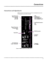
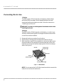
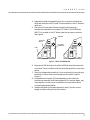

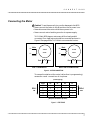
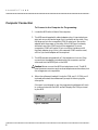
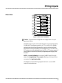


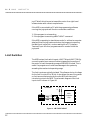
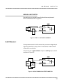

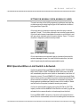
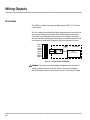


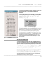
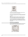
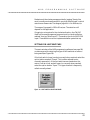
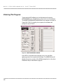


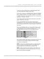

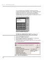


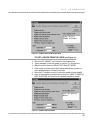
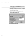
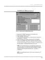


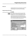

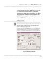


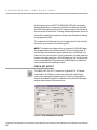
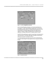

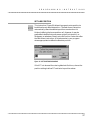
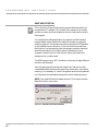
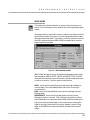


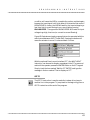


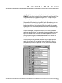
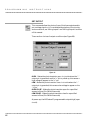

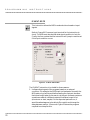


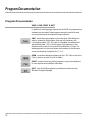


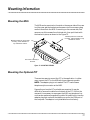
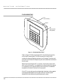

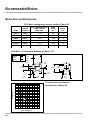
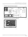


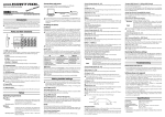


![[SPT-3000] e](http://vs1.manualzilla.com/store/data/005667089_1-a5f3766b3193f6552f250995926a69c5-150x150.png)
![téléchargez le dans son intégralité [ PDF - 28p - 3.62 Mo ] - Athis-Mons](http://vs1.manualzilla.com/store/data/006467605_1-ad483cc3c5528cc7d7f5459746157e0f-150x150.png)