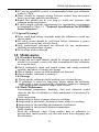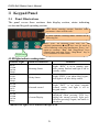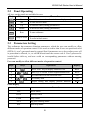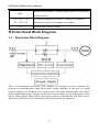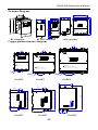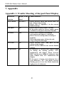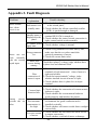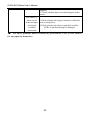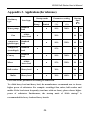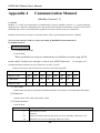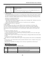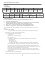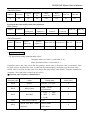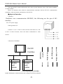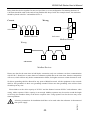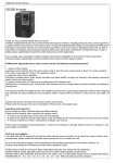
1
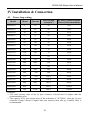
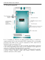
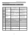
PREFACE Thank you for your choice of EURA DRIVES SoftStarter. As the return of your trust we will provide the perfect quality and wholehearted service to you. HFR2000 adopts three input wires and six output wires design, with output current token function, and on-line monitoring motor current, to realize motor over-load protection. The jogging control function can be used in worksite debugging. Air cooling design ensures system stable running. It is characteristic of convenient connection, smooth starting and motor protection and is widely applicable for starting and protection of three-phase motors in various industries. Notes This instruction manual provides information with respects to installation, parameter-setting, trouble-diagnosing and proper operation. This manual should therefore be kept properly and a careful reading shall be required before any operation attempt to avoid any accidental casualties or damage(s) to the facilities. ★ Special Notice: ▲ Installation, operation, maintenance or checking to this product shall be required before reading carefully this instruction manual and ensuring proper use. ▲ Power shall be disconnected before any wiring. Never touch power terminal with hand or conduct object. Never put or drop foreign substance into soft starter. ▲ When using the bypass contactor, please connect the motor according to the recommended diagram in the user‟s manual, that‟s EURA Soft Starter User’s Manual in order to keep the output exact consistency of softstarter and motor. Otherwise softstarter and motor will be damaged. ▲ Please do not take magneto ohmmeter to measure the insulated resistance between input and output. Otherwise the IGBT and control PCB will be damaged because of high voltage. Please use the magneto ohmmeter to measure the resistance between each phase and between each phase with ground. Also please note that firstly use 3 cables short circuit the each three-phase of input and output separately and take out the entire plugs in control PCB. ▲ Connect input terminals R, S and T to urban power supply of 400V, connect output terminals U, V and W to motor. ▲ Grounding terminal PE shall be properly earth connected (grounding impedance not exceeding 4Ω). ▲ When terminals R, S and T are connected to power supply of 400V and output terminals U, V and W are not connected to motor, it is normal that the voltage of U, V and W is AC400V. The voltage is got by leakage current of module. After U, V and W are connected to motor, the voltage will clear away. ▲ Capacitance can not be connected to the output of soft starter, but capacitance can be connected to the input of soft starter when it is used for improving power factor. ·2· CONTENTS I. Product ……………………………………………………………….. 1 1.1 Nameplate …………………………………………………… 1 1.2 Model Illustration…………………………………………… 1 1.3 Appearance…………………………………………………… 1 1.4 Technical Specifications …………………………………… 2 1.5 Designed Standards for Implementation…………………… 3 1.6 Safe Instructions………………………………………………3 1.7 Precautions…………………………………………………… 3 1.8 Maintenance…………………………..…………………… 4 II. Keypad panel………………………………………………………… 5 2.1 Panel Illustrations…………………………………………… 5 2.2 Panel Operating …………………………………………… 6 2.3 Parameters Setting ………………………………………… 6 III. Functional Block Diagram………………………………………… 7 3.1 Functional Block Diagram……………………………… 7 IV. Installation & Connection ………………………………………… 8 4.1 Power Loop Wiring…… …………………………………… 8 4.2 Wiring Recommended………………………………………….9 4.3 Terminal Function…………………………………………… 10 V. Function Parameters ………………………………………………… 11 5.1 Parameters List……………………………………………… 11 5.2 Parameters Instruction………………………………………..12 VI. External Dimension and Mounting Size…………………………… 18 VII. Appendix…………………………………………………………… 19 Appendix 1 Trouble Shooting of Keypad Panel Display …………… 19 Appendix 2 Fault Diagnosis………………………..….. …………… 20 Appendix 3 Applications ……………….…. ………………………… 22 Appendix 4 Communication Manual………………………. ……… 23 EURA Soft Starter User’s Manual I. Product This manual offers a brief introduction of the installation connection for HFR2000 series softstarters, parameters setting and operations, and should therefore be properly kept. Please contact manufacturer or dealer in case of any malfunction during application. 1.1 Nameplate Taking for instance the HFR2000 series 15KW softstarter with 3-phase input, its nameplate is illustrated as Fig 1-1. 3Ph: Three-phase input, 400V 50/60Hz: input voltage range and rated frequency. EURA DRIVES ELECTRIC CO., LTD SOFTSTARTER MODEL INPUT IP20 HFR1015 3PH RATED 30A CURRENT SCOPE AC-53b AC 400V 50/60Hz MATCHED MOTOR CODE 15KW TRIP CLASS 10 BAR Fig 1-1 Nameplate Illustration 1.2 Model Illustration: Taking for instance as the HFR2000 series with 3-phase input HFR 2 □□□ Adaptive motor power(KW) 2000 Series Bypass Model EURA Softstarter 1.3 Appearance The external structure of HFR2000 series softstarter is metal housings and all the installation is wall hanging type. Metal housing uses advanced exterior plastic- spraying and powder-spraying process on the surface with elegant color. HFR2000 series softstarter 15KW to 55KW adopt structure of takedown single door spindle, softstarter 75KW to 500KW adopt sliding cover structure, easy to wiring and maintain. ·1· EURA Soft Starter User’s Manual Softstarter ! CAUTION 1) Do not connect output terminals(U.V.W) to the power supply 2) Perform parts replacement after discharge is finished 3) Do not re-set while the motor is rotating Takedown appearance for 15-55KW Takedown appearance for 75-500KW 1.4 Technical Specifications Power supply AC 400V±15%, 50/60Hz (It is supplied by interior, users need not supply power.) Input power supply AC 400V±15%, 50/60Hz Applicable motor Common asynchronism motor Startup mode Stop mode Relay output Startup frequency Protection function Display Protection level Cooling mode Installation mode Environment conditions Voltage ramp startup (1~120 seconds), current limiting startup (150~400% Ie), voltage kick startup, jogging start Free stop, soft stop (1~60 seconds) Delay running output, fault output, full voltage output (by pass) [contact dot: 5A, 250VAC] Advise: not exceeding fifteen times per hour Out phase, over-load, over current over-heating. LED nixie tube showing present output frequency, types of faults, and parameters for the system and operation, LED indicators showing the current working status of softstarter. IP20 Air cooling Hanging type Equipment Location In an indoor location, Prevent exposure from direct sunlight, Free from dust, tangy caustic gases, flammable gases, steam or the salt-contented, etc. ·2· EURA Soft Starter User’s Manual Environment Temperature Environment Humidity Applicable motor -10℃~+50℃ Below 90% (no water-bead coagulation) Vibration Strength Height above sea level 15-500KW Below 0.5g (acceleration) 1000m or below 1.5 Designed Standards for Implementation GB14048.6-2008 Low-voltage switchgear and control-gear contactors and motor-starters Section2: AC semiconductor motor controllers and starters(include softstarter) 1.6 Safe instructions Please check the model in the nameplate and the rated value of the softstarter. Please do not use the damaged softstarter in transit. Installation and application environment should be free of rain, drips, steam, dust and oily dirt, without corrosive or flammable gases or liquids, metal particles or metal powder. Environment temperature within the scope of -10℃~+50℃. Please install softstarter away from combustibles. Do not drop anything into the softstarter. The reliability of softstarter relies heavily on the temperature. The around temperature increases by 10℃, softstarter life will be halved. Because of the wrong installation or fixing, the temperature of softstarter will increase and the softstarter will be damaged. softstarter is installed in a control cabinet, and smooth ventilation should be ensured and softstarter should be installed vertically. If there are several softstarters in one cabinet, in order to ensure ventilation, please install softstarters side by side. If it is necessary to install several softstarters up and down. 1.7 Precautions 1.7.1 Instructions for use Never touch the internal elements within 15 minutes after power off. Wait till it is completely discharged. Input terminals R, S and T are connected to power supply of 400V while output terminals U, V and W are connected to motor. Proper grounding should be ensured with grounding resistance not exceeding 4Ω, separate grounding is required for motor and softstarter. Grounding with series connection is forbidden. Load switch is forbidden at output while softstarter is in operation. ·3· EURA Soft Starter User’s Manual AC reactor or/and DC reactor is recommended when your softstarter is above 37KW. There should be separate wiring between control loop and power loop to avoid any possible interference. Signal line should not be too long to avoid any increase with common mode interference. It shall comply with the requirements for surrounding environment as stipulated in Table 1-1 “Technical Specifications for HFR2000 Series Softstarter”. 1.7.2 Special Warning!! Never touch high-voltage terminals inside the softstarter to avoid any electric shock. All safety covers should be well fixed before softstarter is power connected, to avoid any electric shock. Only professional personnel are allowed for any maintenance, checking or replacement of parts. No live-line work is allowed. 1.8 Maintenance 1.8.1 Periodic Checking Cooling fan and wind channel should be cleaned regularly to check whether it is normal, remove the dust accumulated in the softstarter on a regular basis. Check softstarter‟s input and output wiring and wiring terminals regularly and check if wirings are ageing. Check whether screws on each terminals are fastened. Check whether softstarter is corrosive. 1.8.2 Storage Please put the softstarter in the packing case of manufacture. If softstarter is stored for long time, please charge the softstarter within half a year to prevent the electrolytic capacitors damaged. The charging time should be longer than 5 hours. 1.8.3 Daily Maintenance Environment temperature, humidity, dust and vibration would decrease the life of softstarter so daily maintenance is necessary for softstarter. Daily inspecting: Inspecting for noise of motor when it is working. Inspecting for abnormal vibration of motor when it is working. Inspecting for the installing environment of softstarter. Inspecting for the fan and softstarter temperature. Daily cleaning: Keep the softstarter clean. Clean surface dust of softstarter to prevent dust, metal powder, oily dirt and water from dropping into the softstarter. ·4· EURA Soft Starter User’s Manual II Keypad Panel 2.1 Panel Illustrations The panel covers three sections: data display section, status indicating section and keypad operating section LED shows running current, function code, parameter value or fault code. 4 LEDs indicate working status. Details are as following list. Press “Fun” for function code, and “set” for original parameters.▲and▼keys can be used to select function codes and parameters. Press “set” again to confirm. “Run” and “Stop/Reset” keys control start and stop. Press “Stop/Reset” key to reset softstarter in fault status. Keypad Panel 4 LED lights indicate working status: Indicate Light RUN○ FWD● DGT● FRQ● RUN● FWD○ DGT● FRQ● RUN● FWD● DGT○ FRQ● Status of Softstarter Remarks Running Status Light “RUN” is on in running state after startup finished and light is off in standby status. Delay Status Light “FWD” is on when delay begins, and light is off after delay ended. External control Light “DGT” is on when external control works, and light is off in keypad status. Light “FRQ” is on, and current is displayed when pressing FUN key Current Display during the startup process, light goes off when pressing it again, and status is displayed. ○ indicates the light is on, ● indicates the light is off RUN● FWD● DGT● FRQ○ ·5· EURA Soft Starter User’s Manual 2.2 Panel Operating All keys on the panel are available for user. Keys Names Fun Fun To call function code and switch over display mode. Remarks Set Set To call and save data. ▲ Up To increase data (setting parameters) ▼ Down To decrease data (setting parameters) Run Run Stop/reset Stop or reset 2.3 To start softstarter To stop softstarter To reset in fault status Parameters Setting This softstarter has numerous function parameters, which the user can modify to effect different modes of operation control. User needs to realize that if user sets password valid (HF30=1), user‟s password must be entered first if parameters are to be set after power off or protection is effected, i.e., to call HF40 and enter the correct code 8. User‟s password is invalid before delivery, and user could set corresponding parameters without entering password. User can modify to effect different modes of operation control Steps Keys Fun 1 2 ▲ or 3 Set 4 ▲ or 5 set Panel display ▼ Operation Press “Fun” key to display function code HF01 Press “Up” or “Down” to select required function code HF09 To read data set in the function code ▼ Display To modify data Finish setting and display present function code Items Remarks -HF- Reset status RUN Startup status STOP Stop status OUT By pass running status SST Soft stop status ·6· 150 350 HF09 EURA Soft Starter User’s Manual DEL_ Startup interval status(During startup interval to operate the displayed item) PC、OC1、OC2、 PC protect, Startup over current 1, Startup over current 2, OL、OH、PF 10 Startup over load, over heating and out phase. Remain time of delay startup III Functional Block Diagram 3.1 Functional Block Diagram Three reverse-parallel connection SCR modules are adopted as power element. By picking up synchronization signal from input voltage sampling, it can pick up output current sampling for feedback fuzzy control, trace the phase automatically and control phase displacement angle. Voltage can thus be increased step by step, and startup current will be under control. After startup, the bypass contactor will make the SCR short circuit. The motor will finally be driven into the electricity network for operation. ·7· EURA Soft Starter User’s Manual IV Installation & Connection 4.1 Power loop wiring Matched Motor Rated Current Lead Section Area(mm2) By Pass Contactor Rated Current (Recommended) HFR2015 15 30 16 35A HFR2022 22 45 16 50A HFR2030 30 60 25 65A HFR2037 37 75 25 80A HFR2045 45 90 35 100A HFR2055 55 110 35 120A HFR2075 75 150 50 165A HFR2090 90 180 70 190A HFR2110 110 220 70 250A HFR2132 132 260 95 280A HFR2160 160 320 120 350A HFR2200 200 400 150 440A HFR2220 220 440 185 500A HFR2250 250 500 240 500A HFR2280 280 560 240 600A HFR2315 315 630 150*2 630A HFR2355 355 700 150*2 800A HFR2400 400 800 185*2 900A HFR2450 450 900 240*2 1000A Model 1000 HFR2500 500 1000A 240*2 Remarks: 1. The rated current value of the by pass contactor selected must be higher than the recommending value. 2. The capacity of by pass output relay of the softstarter is 7A/250AC, when the by pass contactor‟s loops current is higher than this capacity then add up a middle relay is recommended. ·8· EURA Soft Starter User’s Manual 4.2 Wiring Recommended R, S, T terminals of softstarter are input terminals while U, V and W are output terminals. QF is auto air breaker, KM is contactor, RJ is over heating protection relay, RD1 is fuse, L11is N connected to 230V. And L11-N is forbidden being connecting to 400V. ! PE Grounding wire should be as short as possible, and should be connected to the nearest grounding point, better on the installation board against the soft starter. Installation board should also be grounded. ! Please connect motor with the phase-sequence recommended by manual. Correctly connect softstarter output with bypass contactor. Otherwise softstarter and motor will be ruined. ·9· EURA Soft Starter User’s Manual 4.3 Terminal Function Y1 Y2 Y3 T1 T2 T3 30A 30B 30C IM GND CM RUN STOP BX RST GND JOG CM Terminal Number Y1 Y2 Y3 T1 T2 T3 30A 30B Terminal Name Delay Start Terminal GND When delaying start:Y2-Y1 opened, Y3-Y1 closed, the contacts of relay will be reversed after delay start Technical Parameters Capacity:7A/250VAC Y1:middle end Y2-Y1 normally closed Y3-Y1 normally opened After startup :T2-T1 opened, T3-T1 closed, for turnover to by By pass Contactor pass contactor or middle relay after startup Terminal Capacity:7A/250VAC T1:middle end T2-T1 normally closed T3-T1 normally opened Fault Output Terminal Capacity:7A/250VAC 30A:middle terminal 30B-30A normal close 30C-30Anormal open 30C IM Description During fault:30B-30A open 30C-30A close,for fault output Current token Output current is proportional to External load resistance output terminal motor current. should be lower than 500Ω Current token Forbidden connecting CM IM output grounding grounding to GND. RUN Running Terminal RUN-CM close for running status STOP Stop Terminal BX Free Stop Terminal BX-CM close for free stop status RST Reset Terminal JOG Jogging terminal CM Common Terminal STOP-CM close for stop status RST-CM close for reset status JOG-CM close for jogging startup status CM (External control common terminal) ·10· EURA Soft Starter User’s Manual V Function Parameters 5.1 Parameters List Function No. Function Explanation Data Explanation Mfr Value 0 Keypad control 1 1 External terminal control 2 Keypad + terminal 3 Modbus 4 Keypad + terminal +Modbus 0 Voltage ramp startup 1 1 Current limit startup 2 Kick startup 3 Jogging startup HF00 Control mode HF01 Startup mode HF02 Startup delay time HF03 Stop mode HF04 Torque compensation 0-50% rated voltage 5% HF05 Kick voltage 20-80% rated voltage 50% HF06 Kick time 1-60S 2S HF07 Ramp ascending time 1-120S 20S (15-30kw) 0-600S 0 Free stop 0S 1 Soft stop 0 60S (37-75kw) 100s(90-500kw) HF08 Ramp descending time 1-60S 2S HF09 Startup current limit 150-400% rated current 300% HF10 Startup time interval 1-3600S 240S HF11 Reverting to Mfr‟s Value HF12 Fault memory 1 The latest fault 0 HF13 Fault memory 2 The last but one fault 0 HF14 Fault memory 3 The last but two fault 0 HF15 Reserved HF16 PC protection selection HF17 Voltage ramp OL coefficient 0 No action 1 Action (manufacturer value restored) 0 Invalid 1 Valid 0-60 ·11· 0 1 0 EURA Soft Starter User’s Manual HF18 Out phase selection HF19 Parity check HF20 Communication baud rate 0 Invalid 0 Odd 1200 1: 3: 9600 Communication Address HF22 Selection of ASCII mode 0 and RTU mode 1 HF23 Motor rated current HF24 Close loop Control mode HF25 HF27 Over-load coefficient when bypass running Over-load time when bypass running Jogging torque HF28 IM output range HF29 IM output gain HF30 Password valid or not HF26 2400 2: 4800 ASCII mode RTU mode 10-softstarter rated current Close loop mode 1 Close loop mode 2 50%-200% Softstarter power HF39 Software edition No. HF40 User‟s password 1 0 Subject to model 0 150% 1-100S 20S 1-100% 40% 0 0-20mA 1 4-20mA 0.10-2.00 0 Invalid 1 Valid HF31-HF37 Reserved HF38 2 4: 19200 1-127: Softstarter address 0 1 1 1 Even 2 No check 0 0: HF21 1 Valid 0 1.00 0 Mfr‟s value 15-500 Subject to model Mfr‟s value 0-9999 5.2 Parameters Instruction 0 0 Keypad control 0 1 External terminal control 2 Keypad + terminal 3 Modbus 4 Keypad + terminal +Modbus Control mode selection can be operated directly through the panel keypad, and the manufacturer value is 0. “Keypad control” refers to the start/stop commands given by the “Run” or “stop/reset” key on the keypad. “Terminal control” refers to the start/stop command given by the “Run” and “Stop” terminals. When HF00=3, the running command is given by Modbus. HF00 Control mode ·12· EURA Soft Starter User’s Manual When HF00=4, keypad + terminal + Modbus command are valid at the mean time. 0 Voltage ramp startup 1 1 Current limit startup 2 Kick startup 3 Jogging startup You can start by selecting one of the following three modes: 0 Voltage ramp startup, 1 current limit startup, 2 kick startup, 3 Jogging startup. The manufacturer value is 1 Δ Voltage ramp startup Set HF01 to 0, and set ramp startup time t (HF07) and torque compensation voltage (HF04) U0, the motor will start along with the increasing input voltage, and the speed will accelerate accordingly till its top speed, as shown in Fig1. HF01 Startup mode U Ue U0 t (HF07) T Fig1 Voltage Ramp Startup Feature Curve Δ Current limit startup Set HF01 to 1 and set startup current limit percent Is(HF09)and Torque compensation voltage (HF04). The current of the motor will increase until the voltage ramp reaches Is, then it will stop, and the speed will accelerate to its full speed. After that, the current will decrease to below the rated current Ie, as shown in Fig2: I Is Ie T Fig2 Current Limit Startup Feature Curve ·13· EURA Soft Starter User’s Manual Δ Kick startup Set HF01 to 2, and set ramp start time t (HF07) and torque compensation (HF04), kick time t(HF06). The motor will start rapidly along with the increasing voltage, then the voltage will increase in a ramp way, and the speed will accelerate to its full speed. It is better for startup motor with big inertia, as shown in Fig3: U Ue Us U0 t(HF06) T Fig3 Kick Startup Feature Curve Δ Jogging startup When HF01 is set to 3, and set HF04 and HF27 correctly, jogging startup is valid. Jogging startup is for debugging softstater. When JOG terminal is connected to CM terminal, jogging startup is valid. When jogging startup is valid, softstarter will not be switched to bypass running. U Ue U0 T Fig4 Jogging Startup Feature Curve HF02 Startup delay time 0-600S 0S Startup delay time is set for startup preparation, and the motor will not start in this interval. Count down mode is used for display, and the time can be set from 0 to 600 seconds. When start delay, Y2-Y1 open, Y3-Y1 close, Use these two contacts can output a warning signal. The manufacturer value is set to 0S ·14· EURA Soft Starter User’s Manual HF03 Free stop 0 Free stop 1 Soft stop 0 You can stop by selecting two modes: 0 free stop 1 soft stop. The manufacturer value is set to 0. Free stop means that the voltage of softstarter will reduce directly from Ue to 0V,and the motor will run with inertia till its stop, as shown in Fig5: U Ue T Fig5 Free Stop Feature Curve Soft stop means that the voltage of starter will reduce gradually from Ue to 0V when the voltage drops. The soft stop can help resist “water hammer domino effect”, as shown in Fig6: U Ue t(HF08) T Fig6 Soft Stop Feature Curve HF04 Torque compensation 0-50% rated voltage 5% Torque compensation means to adjust the torque produced by initial voltage U0. The manufacturer value is set to 5%. If the load is heavy, please increase HF04. It is valid in voltage ramp startup and current limit startup. Please note that big value‟s setting is not recommended, increase gradually the value. ·15· EURA Soft Starter User’s Manual HF05 Kick voltage 20-100% rated voltage 50% As for a load with big static torque, an instant high voltage must be inflicted, so that it can start smoothly with the torque big enough, the “kick voltage” range is from 20% to 80% percent of the rated voltage. The manufacturer value is set to 50% rated voltage. Please note that big value‟s setting is not recommended, increase gradually the value. HF06 Kick time 1-60S 2S Kick time means the interval to exert high voltage, adjustable between 1-60S. The manufacturer value is set to 2S. HF07 Ramp ascending time 1-120S 20S (15-30KW) 60S (37-75KW) 100S (90-500KW) Ramp ascending time means the interval to bring the voltage from 0V up to rated voltage Ue. The manufacturer value is set to 20S. HF08 Ramp descending time 1-180S 2S Ramp descending time means the interval to bring the voltage from rated voltage Ue to 0V. The manufacturer value is set to 20S. HF09 Startup current limit 150-400% rated current 300% It works when HF01 is set to 1, startup current limit = HF09*Ie, please adjust HF09 for a successful start, less current is preferred. Please note that big value‟s setting is not recommended, increase gradually the value. HF10 Startup interval 1-3600S 240S This equipment is small-sized, and you can only restart it when the radiator cools down from the previous startup, otherwise the machine will stop due to over-heating protection. The startup interval is adjustable, and no more than 15 startups per hour are preferred for full load startups. The manufacturer value is set to 240S. Reverting to 0 no action HF11 0 Mfr‟s value 1 action (manufacturer value is restored) When the data is in disorder, please restore the manufacturer value by setting data initialization 1. HF12 Fault memory 1 The latest fault 0 HF13 Fault memory 2 The last but one fault 0 Store and display the code of the last but two fault: ·16· EURA Soft Starter User’s Manual Fault Code Fault Details 0 No Fault 1 OH Overheating Fault 2 OC Over current Fault 3 PF Out phase Fault 4 OL2 Over load or jam Fault 5 OL1 Over load or jam Fault HF14 Fault memory 3 The latest fault current 0 The latest fault current is stored in HF14. HF15 Reserved Mfr‟s value It‟s a reserved parameter and user no need to setup. HF16 PC protection selection 0 invalid 1 valid 1 When HF16 is set to 1, the function is valid. It is used to protect the setting of motor and softstarter. HF17 Voltage ramp OL 0-60 0 coefficient Set overload time protection coefficient in the voltage ramp startup. When OL malfunction occurs in the voltage ramp startup, please increase this parameter. HF18 Out phase selection 0 invalid 1 valid 1 HF18 is out phase selection, 0 means out phase function is invalid, 1 means this function is valid, Mfr‟s value is 1. HF19 Parity check 0 Odd 1 Even 2 No check 0 Set the mode of Parity check. The manufacturer value is set to Odd check. HF20 Communication baud rate 0: 2: 4: 1200 4800 19200 1: 2400 3: 9600 2 Set the communication baud rate. The manufacturer value is 4800. HF21 Communication Address 1-127: Softstarter address Set softstarter address. The manufacturer value is 1. ·17· 1 EURA Soft Starter User’s Manual HF22 Selection of ASCII mode 0 ASCII mode and RTU mode 1 RTU mode 0 Set communication mode. The manufacturer value is set to ASCII mode. HF23 Motor rated current 10-softstarter rated current Subject to model This function code is applied for setting motor startup current limit value and overload protection when bypass running. Please set it correctly. Close loop Control 0 Close loop mode 1 0 mode 1 Close loop mode 2 Set 0 means close loop mode 1, set 1 means close loop mode 2. The manufacturer value is 0, the close loop mode 1 is fit for most loads, but centrifugal fan or other big inertia load will cause the unsteady starting. The close loop mode 2 is recommended for this situation. Over-load coefficient 50%-200% HF25 150% when bypass running The Mfr‟s value of HF25 equals to 150% times of motor rated current (HF23). HF25 and HF24 HF26 are applied to over-load protection for softstarter. HF26 Over-load time when 1-100S bypass running HF27 Jogging torque 1-100% 20S 40% Jogging torque is 40% times of rated torque. Target torque is set by this parameter when jogging startup is valid. The value should be lower than 80% times of rated torque. HF28 IM output range 0 0 0-20mA 1 4-20mA When motor is in startup process, the IM output range corresponds to 5 times of motor rated current (HF23). After softstarter runs in bypass status and motor is running, IM output range corresponds to 2 times of motor rated current (HF23). Softstarter will switch automatically, and users do not need to set it. HF29 IM gain 0.10-2.00 1.00 HF29 is used to adjust IM output when softstarter stops. The Mfr‟s value is 1.00. HF30 HF31-HF37 HF38 Password valid or not 0 Invalid 1 Valid 0 Reserved Softstarter Power 15-500 ·18· Subject to model EURA Soft Starter User’s Manual HF39 Software Edition No. Mfr‟s value HF30 will display the Edition No. of software. User can only check it. HF40 User‟s password 0 0-9999 6. External Dimension and Mounting Size Mounting Size (W×L) HFR2015 External Dimension (A×B×H) 370×200×220 HFR2022 370×200×220 150×350 HFR2030 HFR2037 370×200×220 370×200×220 150×350 150×350 HFR2045 HFR2055 370×200×220 370×200×220 150×350 150×350 HFR2075 HFR2090 487.5×254×276.5 487.5×254×276.5 HFR2110 Model 150×350 Screw Structure Code M8 M8 RC1 M8 RC1 RC1 M8 M8 RC1 RC1 RC1 200×424.5 200×424.5 M8 M8 M8 RC2 RC2 487.5×254×276.5 200×424.5 M8 RC2 HFR2132 HFR2160 487.5×254×276.5 487.5×254×276.5 200×424.5 200×424.5 M8 M8 RC2 RC2 HFR2200 HFR2220 555×364.5×351.5 555×364.5×351.5 322×475 322×475 M8 M8 RC3 RC3 HFR2250 555×364.5×351.5 322×475 M8 RC3 HFR2280 HFR2315 555×364.5×351.5 555×364.5×351.5 322×475 322×475 M8 M8 RC3 RC3 HFR2355 HFR2400 660×475.5×317.5 660×475.5×317.5 402×607.5 402×607.5 M10 M10 RC4 RC4 HFR2450 660×475.5×317.5 402×607.5 M10 RC4 HFR2500 660×475.5×317.5 402×607.5 M10 RC4 Installation of copper platoon L1*L2*L3 S1*S2*S3 RC2 25X455X70 55X162X162 RC3 30X525X102 55X201X211 RC4 44X628X151 237X79X68 Structure Code ·19· Remarks Metal Hanging Type EURA Soft Starter User’s Manual Structure Diagram: A W B PASSED L H Softstarter ! CAUTION 1) Do not re-set while the motor is rotating 2) Perform parts replacement after discharge is finished 3) Do not connect output terminals(U.V.W) to the power supply RC2-RC3 Structure RC1 Structure RC4 structure Copper platoon structure diagram L1 L1 L1 Softstarter L1 L3 L2 Softstarter Softstarter ! CAUTION 1)Do not re-set while the motor is rotating 2)Perform parts replacement after discharge is finished 3)Do not connect output terminals(U.V.W) to the power supply ! ! CAUTION 1) Do not re-set while the motor is rotating 2) Perform parts replacement after discharge is finished 3) Do not connect output terminals(U.V.W) to the power supply CAUTION 1) Do not re-set while the motor is rotating 2) Perform parts replacement after discharge is finished 3) Do not connect output terminals(U.V.W) to the power supply L3 Φ10 U M8 M12 For RC2 W V L3 Φ10 Φ11 L3 M12 For RC3 For RC4 S1 S2 S1 S1 S3 For RC2 S3 S3 For RC3 ·20· A HZ V AC AC KW PH 3PH V PASSED 50/60HZ PASSED L2 L2 L2 PASSED S2 S2 For RC4 EURA Soft Starter User’s Manual 7. Appendix Appendix 1. Trouble Shooting of Keypad Panel Display Protection Display in the function panel Over current OC1/OC2 Out phase P.F. Overheat OH Over load OL PC protection PC Counter measures *Please decrease HF04 and increase HF07 in the voltage ramp startup. *Please refer to Appendix 2 in the current limited startup. *Please check if power input is normal. *If the fault caused by power supply, please set HF18=0, Out phase function is invalid. *Please check softstarter installation environment and improve ventilation, *Please decrease startup times if startup is frequent. *When the temperature fell into the safe range, OH protection stops. *Please increase HF17 and HF07 in the voltage ramp startup *Please increase HF09 in the current limited startup. *If softstarter is switched into bypass within 1S during the starting process, “PC” malfunction will display. Please increase HF07 and decrease HF09. If softstarter runs alone without load, “PC” malfunction will display. *If the power of motor and softstarter has a great difference, “PC” will display because starting process is too fast. Please match the right power of softstarter. ·21· EURA Soft Starter User’s Manual Appendix 2. Fault Diagnosis Problems Motor sounds buzz, when power is on Status explanation Trouble shooting 1. Check whether the bypass contactor is blocked Soft starter is in at the closed place, standby state 2. Check whether the silicon controlled rectifier (SCR) is spark-through or damaged. 1. In external control state, check whether the Standby status is terminal RUN-CM is turned on; displayed in the 2. Check whether the control circuit connection is panel right, control switch works normally. No control power 1. Check whether voltage is normal. supply state 1. Check every parameter set value one by one, Wrong parameter make sure that the set values match the Motor can not set practical parameters of motor, 2. Check the current limit value work normally with the startup Phase loss Check three phases‟ voltage, judge whether there signal input. occurs during is phase loss and eliminate fault startup 1. Check whether the connection of output terminals of soft starter and what of motor is Wire right and reliable, connection of 2. Check the input terminals‟ voltage, judge motor is open whether internal circuit of motor is open, 3. Check whether there is phase loss in input terminal 1. Check whether the startup current set is right, 2. Check whether the connection of current mutual Current limit inductor is right, function fails 3. Check whether the current mutual inductor works properly, and matches the motor. Startup current 1. Check whether soft starter installation Environment environment has good ventilation and is exceeds the set temperature is installed vertically, value too high 2. Check whether soft starter avoids direct sunlight successfully, 1. Check whether the soft starter has short circuit Over run current in output connection , of motor 2. Check whether overload of motor or damage ·22· EURA Soft Starter User’s Manual happens, 3. Check whether phase loss fault happens in the motor. Soft starter is short circuit between input and output terminal connection 1.Check whether the bypass contactor is blocked at the closed place, 2.Check whether the silicon controlled rectifier (SCR) is sparked through or damaged The above problems must be handled by professionals. Users are not allowed for any repair by themselves. ·23· EURA Soft Starter User’s Manual Appendix 3. Applications (for reference) Machinery type Water pump Fan Load type Startup mode Voltage Ramp Standard load A little heave load Parameters setting Current limited Torque (%) Current (%) ● 10% 300% ● 20% Startup time (S) 10 30 10 30 10 30 10 30 compressor (piston-type) Standard load compressor (centrifugal) Standard load Convey Standard load ● 10% 300% 10 30 Mixer A little heave load ● 15% 350% 20 40 Ball crusher Heavy load 30 60 Muller Heavy load 30 60 ● ● 10% 350% 15% ● 30% ● 30% 400% Users can set the parameters according to actual load. To a little heavy load and heavy load, the manufacturer recommend user to choose higher power of softstarter. For example: centrifugal fan, mixer, ball crusher and muller. If the load starts frequently (ten times with one hour), please choose higher power of softstarter. Furthermore, the startup mode of “Kick startup” is recommended for heavy load and heavy inertia. ·24· EURA Soft Starter User’s Manual Appendix 4 Communication Manual (Modbus Version 1.7) I. General Modbus is a serial and asynchronous communication protocol. Modbus protocol is a general language applied to PLC and other controlling units. This protocol has defined an information structure which can be identified and used by a controlling unit regardless of whatever network they are transmitted. Modbus protocol does not require a special interface while a typical physical interface is RS485. You can read reference books or ask for the details of MODBUS from manufactures. II. Modbus Protocol 1. Overall Description (1) Transmission mode 1) ASCII Mode When controllers are setup to communicate on a Modbus network using ASCII mode, each 8–bit byte in a message is sent as two ASCII characters. For example, 31H (hexadecimal data) include two ASCII characters‟3(33H)‟,‟1(31H)‟. Common characters, ASCII characters are shown in the following table: Characters „0‟ „1‟ „2‟ „3‟ „4‟ „5‟ „6‟ „7‟ ASCII Code 30H 31H 32H 33H 34H 35H 36H 37H Characters „8‟ „9‟ „A‟ „B‟ „C‟ „D‟ „E‟ „F‟ ASCII Code 38H 39H 41H 42H 43H 44H 45H 46H 2) RTU Mode In RTU mode, one Byte is expressed by hexadecimal format. For example, 31H is delivered to data packet. (2) Baud rate Setting range: 1200, 2400, 4800, 9600, 19200 (3) Frame structure: 1) ASCII mode Byte 1 7 0/1 1/2 Function Start Bit (Low Level) Data Bit Parity Check Bit (None for this bit in case of no checking. Otherwise 1 bit) Stop Bit (1 bit in case of checking, otherwise 2 bits) ·25· EURA Soft Starter User’s Manual 2) RTU mode Byte Function 1 8 0/1 1/2 Start Bit (Low Level) Data Bit Parity Check Bit (None for this bit in case of no checking. Otherwise 1 bit) Stop Bit (1 bit in case of checking, otherwise 2 bits) (4) Error Check 1) ASCII mode Longitudinal Redundancy Check (LRC): It is performed on the ASCII message field contents excluding the „colon‟ character that begins the message, and excluding the CRLF pair at the end of the message. The LRC is calculated by adding together successive 8–bit bytes of the message, discarding any carries, and then two‟s complementing the result. A procedure for generating an LRC is: 1. Add all bytes in the message, excluding the starting „colon‟ and ending CRLF. Add them into an 8–bit field, so that carries will be discarded. 2. Subtract the final field value from FF hex (all 1‟s), to produce the ones–complement. 3. Add 1 to produce the twos–complement. 2) RTU Mode Cyclical Redundancy Check (CRC): The CRC field is two bytes, containing a 16–bit binary value. The CRC is started by first preloading a 16–bit register to all 1‟s. Then a process begins of applying successive 8–bit bytes of the message to the current contents of the register. Only the eight bits of data in each character are used for generating the CRC. Start and stop bits, and the parity bit, do not apply to the CRC. A procedure for generating a CRC-16 is: 1. Load a 16–bit register with FFFF hex (all 1‟s). Call this the CRC register. 2. Exclusive OR the first 8–bit byte of the message with the high–order byte of the 16–bit CRC register, putting the result in the CRC register. 3. Shift the CRC register one bit to the right (toward the LSB), zero–filling the MSB. Extract and examine the LSB. 4. (If the LSB was 0): Repeat Step 3 (another shift). (If the LSB was 1): Exclusive OR the CRC register with the polynomial value A001 hex (1010 0000 0000 0001). 5. Repeat Steps 3 and 4 until 8 shifts have been performed. When this is done, a complete 8–bit byte will have been processed. When the CRC is appended to the message, the low-order byte is appended first, followed by the high-order byte. 2. Command Type & Format (1) The listing below shows the function codes. code name description 03 Read Holding Registers Read the binary contents of holding registers in the slave. (Less than 10 registers once time ) 06 Preset Single Register Preset a value into holding register ·26· EURA Soft Starter User’s Manual (2) Format 1) ASCII mode Start Address Function Data LRC check : Softstarter Function Data Data … Data High-order (0X3A) Address Code Length 1 … N byte of LRC Low-order byte of LRC End Return (0X0D) Line Feed (0X0A) 2)RTU mode Start Address Function T1-T2-T3-T4 Softstarter Address Function Code Data N data CRC check Low-order byte of CRC High-order byte of CRC End T1-T2-T3-T4 3) Protocol Converter It is easy to turn a RTU command into an ASCII command followed by the lists: 1) 2) Use the LRC replacing the CRC. Transform each byte in RTU command into a corresponding two byte ASCII. For example: transform 0x03 into 0x30, 0x33 (ASCII code for 0 and ASCII code for 3). 3) Add a „colon‟ ( : ) character (ASCII 3A hex) at the beginning of the message. 4) End with a „carriage return – line feed‟ (CRLF) pair (ASCII 0D and 0A hex). So we will introduce RTU Mode in followed part. If you use ASCII mode, you can use the up lists to convert. (3) Address and meaning The part introduces softstarter running, softstarter status and related parameters setting. Description of rules of function codes parameters address: 1) Use the function code as parameter address 1. General Series: High-order byte: 01~09 (hexadecimal) Low-order byte: 00~3C For example: F114 (display on the board), parameter address is 010E (hexadecimal). 2. Softstarter series High-order byte: 00 Low-order byte: 00~3C For example: HF14 (display on the board), parameter address is 000E (hexadecimal). Note: in this situation, it allows to read six function codes and write only one function code. Some function codes can only be checked but cannot be modified, some function codes can neither be checked nor be modified, some function codes can not be modified in run state, some function codes can not be modified both in stop and run state. In case parameters of all function codes are changed, the effective range, unit and related instructions shall refer to user manual of related series of softstarters. Otherwise, unexpected results may occur. 2) Use different parameters as parameter address (The above address and parameters descriptions are in hexadecimal format, for example, the decimal ·27· EURA Soft Starter User’s Manual digit 4096 is represented by hexadecimal 1000). 1. Running status parameters Parameters Address Parameter Description(read only) 1001 The following is softstarter status. The high-order byte is 0, and low-order byte is the status of softstarter. 0. standby 1. running 2. OC1 protection 3. OC2 protection 4. PF protection 5. OH protection 6. OL protection 1002 Output current 2. Control commands Parameters Address 2000 Parameters Description(write only) Command meaning: 0003:Deceleration stop 0004:Free stop 0008:Run(no directions) 0009:Fault reset 3. Communication parameters Parameters Address 3000 Parameters Description(read only) Command meaning: 0000:no error 0001:illegal function 0002: illegal address 0003: illegal parameters 0004: LRC error 0005: CRC error 0006:system locked 4. Response Command Description Parameters Description Response when parameters reading 1、return code value in normal response 2、not allowed to read return FFFF(hex) Response when parameters writing 0001:operate successfully 0002:less than min value 0003:greater than max value 0004:not allowed to change 0005:in fault status 0006:system locked ·28· EURA Soft Starter User’s Manual The following is response command when read/write parameters: Eg1: In RTU mode, change acc time (F007) to 10.0s in NO.01 softatarter. Host Query Address Register Address Hi Function 01 06 Register Address Lo Preset Data Hi 07 00 F0 Preset Data Lo CRC Lo 0A Function code F007 CRC Hi 8B 0C Response Data Lo CRC Lo CRC Hi 04 0A C8 Value: 10.0S Slave Response Address Function Register Address Hi Register Address Lo Response Data Hi 06 F0 07 00 01 Function code F007 Do not allow to change Eg 2:Read status and output voltage from N0.2 softstarter. Host Query Address Function First Register Address Hi First Register Address Lo Register count Hi Register count L0 CRC Lo CRC Hi 02 03 10 00 00 02 C0 F8 Communication Parameters Address 1000H Address Function Byte Count Data Hi Data Lo Data Hi Data Lo Crc Lo Crc Hi Slave Response: 02 03 04 00 02 00 00 68 F3 OC1 protection output current Eg 3: NO.1 softstarter runs forwardly. Host Query: Address Function 01 06 Register Hi Register Lo Write status Hi Write status Lo CRC Lo CRC Hi 20 00 00 01 43 CA Communication parameters address 2000H ·29· Forward running EURA Soft Starter User’s Manual Slave Response: Address Function Register Hi Register Lo Write status Hi Write status Lo CRC Lo CRC Hi 01 06 20 00 00 01 43 CA Writing parameters successfully Eg4: Read the value of F017 from NO.2 softstarter Host Query: Address Function Register Address Hi Register Address Lo 03 F0 11 02 Register Count Hi Register Count L0 CRC Lo CRC Hi 00 01 E7 3C Communication Parameter Address F011H Reading one Register. Slave Response: Address Function 02 03 Register Address Hi Register Address Lo F0 Read status Hi Read status Lo CRC Lo 11 00 04 27 CRC Hi 3F The actual value is 4. 3. Additional Remarks (1) Expressions during communication course: Parameter Values of Current=actual value X 10 Others parameter Values=actual value X 1 Parameter value is the value sent in the data package. Actual value is the actual value of softstarter. After PC/PLC receives the parameter value, it will divide the corresponding coefficient to get the actual value. NOTE: Take no account of radix point of the data in the data package when PC/PLC transmits command to softstarter.. The valid value is range from 0 to 65535. Ⅲ Function codes related to communication Function Code Name HF18 Stop bit HF19 Parity Check HF20 Baud Rate Setting Rang Mfr‟s Value 0 one bit 1 two bits 0 0:Odd 1:Even 2:No checkout 0 0 1200 1 2400 2 4800 3 9600 2 4 19200 HF21 HF22 Soft starter‟s Address 1-127 ASCII and RTU mode 0 ASCII Mode Selection 1 RTU Mode ·30· 1 0 EURA Soft Starter User’s Manual You can read device status and function code value or preset functions value of soft starter regardless of value of HF00. Please set functions code related to communication consonant with the PLC/PC communication parameters, when soft starter communicate with PLC/PC. Ⅳ physical interface 1 interface Hardware uses communication MAX485, the following are the pin of 485 interface. VCC: 5V power supply GND: ground of 5V Connect A+ to A+ of PLC or other converter and connect A -to Bof PLC or other Converter, when soft starter communicate to other devices. 2 Structure of Field Bus PLC/PC ·31· Actual Value Connecting Diagram of Field Bus RS485 Half-duplex communication mode is adopted for EURA softstarter. Status Info EURA soft starter Given Value EURA soft starter Control Command Field Bus EURA Soft Starter User’s Manual Daisy chain the devices together. Do not use 'spur' lines, or a star configuration. Terminating Resistors of 120 Ohms should be used on the ends of long modbus/485 loops. In the first example below, the terminator should be placed at the PLC and modbus device 4. Correct 1 Wrong 2 Soft starter 1 2 3 3 4 Modbus Devices 4 Soft starter Modbus Devices Wrong 4 1 2 3 soft starter Modbus Devices Please note that for the same time in half-duplex connection, only one softstarter can have communication with PC/PLC. Should two or more than two softstarters upload data at the same time, then bus competition will occur, which will not only lead to communication failure, but higher current to certain elements as well. No direct grounding shall be allowed for any point of RS485 network. All the equipment in the network shall be well grounded via their own grounding terminal. Please note that grounding wires will not form closed loop in any case. Please think over the drive capacity of PC/PLC and the distance between PC/PLC and softstarter when wiring. Add a repeaters if drive capacity is not enough. Modbus repeaters may be used to extend the length of the loop, but introduce delay in the device response time. Using repeaters on slow devices may cause timeout problems. All wiring connections for installation shall have to be made when the softstarter is disconnected from power supply. 11102001 ·32·