1
Preliminary Application Note
78K0
8-Bit Single-Chip Microcontrollers
Flash Memory Self Programming
Kx2/Fx2/Lx2/Dx2/Lx3/LIN4/uCFL/Ix2/Kx2-L
Document No. U18990EE2V0AN00
Date published Feb 2009
© NEC Electronics 2009
Printed in Germany
Legal Notes
2
•
The information contained in this document is being issued in
advance of the production cycle for the product. The parameters
for the product may change before final production or NEC
Electronics Corporation, at its own discretion, may withdraw the
product prior to its production.
•
No part of this document may be copied or reproduced in any form
or by any means without the prior written consent of NEC
Electronics. NEC Electronics assumes no responsibility for any
errors that may appear in this document.
•
NEC Electronics does not assume any liability for infringement of
patents, copyrights or other intellectual property rights of third
parties by or arising from the use of NEC Electronics products listed
in this document or any other liability arising from the use of such
products. No license, express, implied or otherwise, is granted under
any patents, copyrights or other intellectual property rights of NEC
Electronics or others.
•
Descriptions of circuits, software and other related information in this
document are provided for illustrative purposes in semiconductor
product operation and application examples. The incorporation of
these circuits, software and information in the design of a customer's
equipment shall be done under the full responsibility of the customer.
NEC Electronics assumes no responsibility for any losses incurred
by customers or third parties arising from the use of these circuits,
software and information.
•
While NEC Electronics endeavors to enhance the quality, reliability
and safety of NEC Electronics products, customers agree and
acknowledge that the possibility of defects thereof cannot be
eliminated entirely. To minimize risks of damage to property or injury
(including death) to persons arising from defects in NEC Electronics
products, customers must incorporate sufficient safety measures in
their design, such as redundancy, fire-containment and anti-failure
features.
•
NEC Electronics products are classified into the following three
quality grades: "Standard", "Special", and "Specific". The "Specific"
quality grade applies only to NEC Electronics products developed
based on a customer-designated "quality assurance program" for a
specific application. The recommended applications of an NEC
Electronics product depend on its quality grade, as indicated below.
Customers must check the quality grade of each NEC Electronics
products before using it in a particular application.
"Standard": Computers, office equipment, communications
equipment, test and measurement equipment, audio and visual
equipment, home electronic appliances, machine tools, personal
electronic equipment and industrial robots.
"Special": Transportation equipment (automobiles, trains, ships,
etc.), traffic control systems, anti-disaster systems, anti-crime
systems, safety equipment and medical equipment (not specifically
designed for life support).
"Specific": Aircraft, aerospace equipment, submersible repeaters,
nuclear reactor control systems, life support systems and medical
equipment for life support, etc.
Preliminary Application Note U18990EE2V0AN00
The quality grade of NEC Electronics products is "Standard" unless otherwise
expressly specified in NEC Electronics data sheets or data books, etc. If
customers wish to use NEC Electronics products in applications not intended by
NEC Electronics, they must contact an NEC Electronics sales representative in
advance to determine NEC Electronics' willingness to support a given application.
(Note)
(1) "NEC Electronics" as used in this statement means NEC Electronics
Corporation and also includes its majority-owned subsidiaries.
(2) "NEC Electronics products" means any product developed or manufactured
by or for NEC Electronics (as defined above).
Preliminary Application Note U18990EE2V0AN00
3
Regional Information
Some information contained in this document may vary from country to country. Before
using any NEC product in your application, please contact the NEC office in your country
to obtain a list of authorized representatives anddistributors. They will verify:
•
Device availability
•
Ordering information
•
Product release schedule
•
Availability of related technical literature
•
Development environment specifications (for example, specifications for
third-party tools and components, host computers, power plugs, AC
supply voltages, and so forth)
•
Network requirements
In addition, trademarks, registered trademarks, export restrictions, and otherlegal
issues may also vary from country to country.
NEC Electronics Corporation
1753, Shimonumabe, Nakahara-ku,
Kawasaki, Kanagawa 211-8668, Japan
Tel: 044 4355111
http://www.necel.com/
[America]
[Europe]
[Asia & Oceania]
NEC Electronics America, Inc.
2880 Scott Blvd.
Santa Clara, CA 95050-2554,
U.S.A.
Tel: 408 5886000
http://www.am.necel.com/
NEC Electronics (Europe) GmbH
Arcadiastrasse 10
40472 Düsseldorf, Germany
Tel: 0211 65030
http://www.eu.necel.com/
NEC Electronics (China) Co., Ltd
7th Floor, Quantum Plaza, No. 27
ZhiChunLu Haidian District,
Beijing 100083, P.R.China
Tel: 010 82351155
http://www.cn.necel.com/
United Kingdom Branch
Cygnus House, Sunrise Parkway
Linford Wood, Milton Keynes
MK14 6NP, U.K.
Tel: 01908 691133
Succursale Française
9, rue Paul Dautier, B.P. 52
78142 Velizy-Villacoublay Cédex
France
Tel: 01 30675800
Tyskland Filial
Täby Centrum
Entrance S (7th floor)
18322 Täby, Sweden
Tel: 08 6387200
Filiale Italiana
Via Fabio Filzi, 25/A
20124 Milano, Italy
Tel: 02 667541
Branch The Netherlands
Steijgerweg 6
5616 HS Eindhoven,
The Netherlands
Tel: 040 2654010
NEC Electronics Shanghai Ltd.
Room 2511-2512, Bank of China
Tower,
200 Yincheng Road Central,
Pudong New Area,
Shanghai 200120, P.R. China
Tel: 021 58885400
http://www.cn.necel.com/
NEC Electronics Hong Kong Ltd.
12/F., Cityplaza 4,
12 Taikoo Wan Road, Hong Kong
Tel: 2886 9318
http://www.hk.necel.com/
NEC Electronics Taiwan Ltd.
7F, No. 363 Fu Shing North Road
Taipei, Taiwan, R.O.C.
Tel: 02 27192377
NEC Electronics Singapore Pte. Ltd.
238A Thomson Road,
#12-08 Novena Square,
Singapore 307684
Tel: 6253 8311
http://www.sg.necel.com/
NEC Electronics Korea Ltd.
11F., Samik Lavied’or Bldg., 720-2,
Yeoksam-Dong, Kangnam-Ku, Seoul,
135-080, Korea Tel: 02-558-3737
http://www.kr.necel.com/
4
Preliminary Application Note U18990EE2V0AN00
Table of Contents
Chapter 1
General Information
............................................
7
1.1
Overview . . . . . . . . . . . . . . . . . . . . . . . . . . . . . . . . . . . . . . . . . . . . . . . . . . . . . . . . . . . . . . . . . . . . . . . . . 7
1.2
Work Flow . . . . . . . . . . . . . . . . . . . . . . . . . . . . . . . . . . . . . . . . . . . . . . . . . . . . . . . . . . . . . . . . . . . . . . . . 8
1.3
Bank Number and Block Number . . . . . . . . . . . . . . . . . . . . . . . . . . . . . . . . . . . . . . . . . . . . . . . . . . . 10
1.4
Processing Time and Interrupt Acknowledging . . . . . . . . . . . . . . . . . . . . . . . . . . . . . . . . . . . . . . 14
Chapter 2
Programming Environment
. . . . . . . . . . . . . . . . . . . . . . . . . . . . . . . . . . 17
2.1
Hardware Environment . . . . . . . . . . . . . . . . . . . . . . . . . . . . . . . . . . . . . . . . . . . . . . . . . . . . . . . . . . . . 17
2.2
Software Environment . . . . . . . . . . . . . . . . . . . . . . . . . . . . . . . . . . . . . . . . . . . . . . . . . . . . . . . . . . . . . 18
2.2.1
Entry RAM . . . . . . . . . . . . . . . . . . . . . . . . . . . . . . . . . . . . . . . . . . . . . . . . . . . . . . . . . . . . . . . 19
2.2.2
Stack and data buffer . . . . . . . . . . . . . . . . . . . . . . . . . . . . . . . . . . . . . . . . . . . . . . . . . . . . . . 20
Chapter 3
Interrupt Services During Self Programming
. . . . . . . . . . 21
3.1
Overview . . . . . . . . . . . . . . . . . . . . . . . . . . . . . . . . . . . . . . . . . . . . . . . . . . . . . . . . . . . . . . . . . . . . . . . . . 21
3.2
Interrupt Response Time . . . . . . . . . . . . . . . . . . . . . . . . . . . . . . . . . . . . . . . . . . . . . . . . . . . . . . . . . . 24
3.3
Cautions . . . . . . . . . . . . . . . . . . . . . . . . . . . . . . . . . . . . . . . . . . . . . . . . . . . . . . . . . . . . . . . . . . . . . . . . . 26
Chapter 4
Boot Swapping
Chapter 5
Appendix - NEC library
. . . . . . . . . . . . . . . . . . . . . . . . . . . . . . . . . . . . . . . . . . . . . . . . . . . 27
. . . . . . . . . . . . . . . . . . . . . . . . . . . . . . . . . . . . . . . . 31
5.1
Self Programming Library - function prototypes . . . . . . . . . . . . . . . . . . . . . . . . . . . . . . . . . . . . . 31
5.2
Explanation of Self Programming Library . . . . . . . . . . . . . . . . . . . . . . . . . . . . . . . . . . . . . . . . . . .
5.2.1
Open . . . . . . . . . . . . . . . . . . . . . . . . . . . . . . . . . . . . . . . . . . . . . . . . . . . . . . . . . . . . . . . . . . . .
5.2.2
Close . . . . . . . . . . . . . . . . . . . . . . . . . . . . . . . . . . . . . . . . . . . . . . . . . . . . . . . . . . . . . . . . . . . .
5.2.3
Init . . . . . . . . . . . . . . . . . . . . . . . . . . . . . . . . . . . . . . . . . . . . . . . . . . . . . . . . . . . . . . . . . . . . . .
5.2.4
Mode Check . . . . . . . . . . . . . . . . . . . . . . . . . . . . . . . . . . . . . . . . . . . . . . . . . . . . . . . . . . . . .
5.2.5
Blank Check . . . . . . . . . . . . . . . . . . . . . . . . . . . . . . . . . . . . . . . . . . . . . . . . . . . . . . . . . . . . . .
5.2.6
Erase . . . . . . . . . . . . . . . . . . . . . . . . . . . . . . . . . . . . . . . . . . . . . . . . . . . . . . . . . . . . . . . . . . . .
5.2.7
Verify . . . . . . . . . . . . . . . . . . . . . . . . . . . . . . . . . . . . . . . . . . . . . . . . . . . . . . . . . . . . . . . . . . . .
5.2.8
Write . . . . . . . . . . . . . . . . . . . . . . . . . . . . . . . . . . . . . . . . . . . . . . . . . . . . . . . . . . . . . . . . . . . .
5.2.9
EEPROMWrite . . . . . . . . . . . . . . . . . . . . . . . . . . . . . . . . . . . . . . . . . . . . . . . . . . . . . . . . . . . .
5.2.10 Get Security Flags . . . . . . . . . . . . . . . . . . . . . . . . . . . . . . . . . . . . . . . . . . . . . . . . . . . . . . . . .
5.2.11 Get Active Boot Cluster . . . . . . . . . . . . . . . . . . . . . . . . . . . . . . . . . . . . . . . . . . . . . . . . . . . .
5.2.12 Get Block End Address . . . . . . . . . . . . . . . . . . . . . . . . . . . . . . . . . . . . . . . . . . . . . . . . . . . .
5.2.13 Set and Invert Functions . . . . . . . . . . . . . . . . . . . . . . . . . . . . . . . . . . . . . . . . . . . . . . . . . . .
5.3
Sample - Link Directive File . . . . . . . . . . . . . . . . . . . . . . . . . . . . . . . . . . . . . . . . . . . . . . . . . . . . . . . . 51
5.4
Library integration/configuration . . . . . . . . . . . . . . . . . . . . . . . . . . . . . . . . . . . . . . . . . . . . . . . . . . . 52
Chapter 6
Appendix - IAR library . . . . . . . . . . . . . . . . . . . . . . . . . . . . . . . . . . . . . . . . . .
32
33
35
36
37
38
39
40
41
43
45
47
48
49
53
6.1
Self Programming Library - function prototypes . . . . . . . . . . . . . . . . . . . . . . . . . . . . . . . . . . . . . 53
6.2
Explanation of Self Programming Library . . . . . . . . . . . . . . . . . . . . . . . . . . . . . . . . . . . . . . . . . . .
6.2.1
Open . . . . . . . . . . . . . . . . . . . . . . . . . . . . . . . . . . . . . . . . . . . . . . . . . . . . . . . . . . . . . . . . . . . .
6.2.2
Close . . . . . . . . . . . . . . . . . . . . . . . . . . . . . . . . . . . . . . . . . . . . . . . . . . . . . . . . . . . . . . . . . . . .
6.2.3
Init . . . . . . . . . . . . . . . . . . . . . . . . . . . . . . . . . . . . . . . . . . . . . . . . . . . . . . . . . . . . . . . . . . . . . .
6.2.4
Mode Check . . . . . . . . . . . . . . . . . . . . . . . . . . . . . . . . . . . . . . . . . . . . . . . . . . . . . . . . . . . . .
6.2.5
Blank Check . . . . . . . . . . . . . . . . . . . . . . . . . . . . . . . . . . . . . . . . . . . . . . . . . . . . . . . . . . . . . .
6.2.6
Erase . . . . . . . . . . . . . . . . . . . . . . . . . . . . . . . . . . . . . . . . . . . . . . . . . . . . . . . . . . . . . . . . . . . .
6.2.7
Verify . . . . . . . . . . . . . . . . . . . . . . . . . . . . . . . . . . . . . . . . . . . . . . . . . . . . . . . . . . . . . . . . . . . .
Preliminary Application Note U18990EE2V0AN00
54
55
57
58
59
60
61
62
5
6.2.8
6.2.9
6.2.10
6.2.11
6.2.12
6.2.13
Write . . . . . . . . . . . . . . . . . . . . . . . . . . . . . . . . . . . . . . . . . . . . . . . . . . . . . . . . . . . . . . . . . . . .
EEPROMWrite . . . . . . . . . . . . . . . . . . . . . . . . . . . . . . . . . . . . . . . . . . . . . . . . . . . . . . . . . . . .
Get Security Flags . . . . . . . . . . . . . . . . . . . . . . . . . . . . . . . . . . . . . . . . . . . . . . . . . . . . . . . . .
Get Active Boot Cluster . . . . . . . . . . . . . . . . . . . . . . . . . . . . . . . . . . . . . . . . . . . . . . . . . . . .
Get Block End Address . . . . . . . . . . . . . . . . . . . . . . . . . . . . . . . . . . . . . . . . . . . . . . . . . . . .
Set and Invert Functions . . . . . . . . . . . . . . . . . . . . . . . . . . . . . . . . . . . . . . . . . . . . . . . . . . .
63
65
67
69
70
71
6.3
Sample - Linker Command File . . . . . . . . . . . . . . . . . . . . . . . . . . . . . . . . . . . . . . . . . . . . . . . . . . . . . 73
6.4
Library integration/configuration . . . . . . . . . . . . . . . . . . . . . . . . . . . . . . . . . . . . . . . . . . . . . . . . . . . 75
Chapter 7
6
Appendix - Sample Code
. . . . . . . . . . . . . . . . . . . . . . . . . . . . . . . . . . . . . 76
Preliminary Application Note U18990EE2V0AN00
Chapter 1 General Information
1.1 Overview
The 78K0/Kx2/Fx2/Lx2/Dx2/Lx3/LIN4/uCFL/Ix2/Kx2-L series products are
equipped with an internal firmware, which allows to rewrite the flash memory
without the use of an external programmer. In addition to this internal firmware
NEC provide the socalled self-programming library. This library offer an easy-touse interface to the internal firmware functionality. By calling the self programming
library functions from user program, the contents of the flash memory can easily
be rewritten in the field.
Figure 1-1
Caution
Flash Access
•
•
The self programming library rewrites the contents of the flash
memory by using the CPU, registers, and RAM. Thus the user
program cannot be executed while the self programming library is
in process.
The self programming library uses the CPU (register bank 3) and a
work area (entry RAM of 100 bytes).
Preliminary Application Note U18990EE2V0AN00
7
Chapter 1
General Information
Operation Modes
There are three operation modes during selfprogramming.
Mode
Description
Normal Mode
Mode A1
-
execute user application
after RESET operation starts in this mode
-
set up self-programming environment
the firmware can be executed via CALL
08100H
-
used by the firmware only to perform the
command
not visible to the user
Mode A2
-
Figure 1-2
Operation Modes
1.2 Work Flow
The self programming library can be used by a user program written in either Cor assembly language.
The following flowchart illustrates a sample procedure of rewriting the flash
memory by using the self programming library.
8
Preliminary Application Note U18990EE2V0AN00
General Information
Figure 1-3
Flow Explanation
Chapter 1
Flow of Self Programming (rewriting contents of flash memory)
1.
2.
3.
4.
5.
6.
7.
8.
9.
Preprocessing, call the open function FSL_Open.
Preserve and configurate interrupt. (optional)
Set FLMD0 pin level to HIGH.
Call the initialize function FSL_Init to initialize the entry RAM.
Call the mode check function FSL_ModeCheck to examine the
FLMD0 voltage level.
Call the block blank check function FSL_BlankCheck to prove if the
specified block (1KB) is blank.
Call the block erase function FSL_Erase to erase the data of a
specified block (1KB).
Fill the data buffer with data. This data will be written into the flash.
Call the word write function FSL_Write to update 1 to 64 words (each
word equals 4 bytes) of data to a specified address.
Call the block verify function FSL_IVerify to verify a specified block
(1KB) (internal verification).
Postprocessing, call the close function FSL_Close.
Set FLMD0 pin level to LOW.
Retrieve preserved interrupt masks. (optional)
Preliminary Application Note U18990EE2V0AN00
9
Chapter 1
General Information
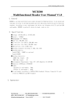
1.3 Bank Number and Block Number
General
The flash memory of all products of the 78K devices are divided in blocks of 1 KB,
but the flash memory addressing in normal operation mode differs from that in
self programming mode.
Furthermore each device is equipped with two boot clusters.
The primary boot cluster (boot cluster 0) addresses from 0000H to 0FFFH, and
temporary boot cluster (boot cluster 1) from 1000H to 1FFFH. Each boot cluster
has 4K bytes of flash size.
A boot cluster stores information like the vector table data, option bytes, self
programming functionlity, etc. For details on the boot cluster, please refer to the
following chapter "Boot Swapping".
under 60K products
Application view:
The memory can be accessed over the whole 60KB using a 16bit addressing.
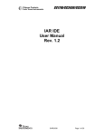
Self programming view:
Erasing, blank checking, and verifying (internal verification) of self programming
are performed in block units. To call these self programming functions, a block
number has to be specified.
The write command is performed in word units (4 bytes). The destination address
must be multiple of 4 and has to be given as 32bit address.
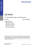
over 60KB products
Application view:
The memory is split in a common and a banked area. The common area is located
from 0000H to 07FFFH and can be accessed by using a 16bit address. The bank
area is located from 08000H to 0BFFFH, where each bank (up to 6 in all, bank 0
to bank 5) can be selected by the bank select register.
Self programming view:
Erasing, blank checking, and verifying (internal verification) of self programming
are performed in block units. To call these self programming functions, a block
number has to be specified.
The write command is performed in word units (4 bytes). The destination address
must be multiple of 4 and has to be given as 32bit address.
10
Preliminary Application Note U18990EE2V0AN00
General Information
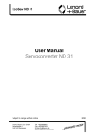
Figure 1-4
Chapter 1
Block Numbers and Boot Clusters (flash memory of up to 60KB)
Preliminary Application Note U18990EE2V0AN00
11
Chapter 1
General Information
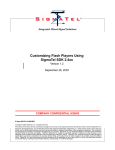
Figure 1-5
12
Block Numbers and Boot Clusters (flash memory of more than 60KB)
Preliminary Application Note U18990EE2V0AN00
General Information
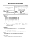
Figure 1-6
Chapter 1
Block number in self programming view
Preliminary Application Note U18990EE2V0AN00
13
Chapter 1
General Information
1.4 Processing Time and Interrupt Acknowledging
The processing time of interrupt varies depending on oscillator in use. For exact
processing time, please refer to the device corresponding user manual.
The following two tables show examples of the processing time of the self
programming library and whether interrupts can be acknowledged. The difference
between this tables is the usage of the source to the main oscillator (internal highspeed oscillator or external system clock).
The self programming functions which acknowledge interrupts will check if nonmasked interrupt is generated during execution and then interrupt the selfprogramming functionality.
For details on interrupt, please refer to the chapter "Interrupt Services During SelfProgramming".
14
Preliminary Application Note U18990EE2V0AN00
1496.5(1496.875)
871.25 (871.375)
863.375 (863.5)
1042.75 (1043.625)
105524.75
FSL_EEPROMWrite
FSL_GetSecurityFlags
FSL_GetActiveBootCluster
FSL_GetBlockEndAddr
FSL_Setxxx, FSL_Invertxxx
790809.375
2691.5(2691.875)
2409(2409.375)
356318
104978.5
502.25 (503.125)
329.125 (239.25)
337 (337.125)
962.25(962.625)
679.75(680.125)
25072.625
36363.25
12236.625
219.625
443.5
541143.125
2157.25(2157.625)
1874.75(1875.125)
355771.75
•
Values in parentheses are used when the write start address structure is placed outside internal high-speed RAM area.
•
This is only an example, for correct timings of the device, please refer to the corresponding user manual.
(*) Please refer to command description for details.
1214(1214.375)
FSL_Write
12770.875
FSL_Blank Check
25618.875
753.875
FSL_Mode Check
FSL_IVerify
977.75
FSL_Init
36909.5
4.25
FSL_Close
FSL_Erase
4.25
Max
Min
Min
Max
Inside short direct addressing range
Outside short direct addressing range
Processing Time (Unit: Microseconds)
Processing Time and Acknowledging Interrrupt (with internal high-speed oscillator)
FSL_Open
Function name
Table 1-1
Acknowledged (*)
Not acknowledged
Not acknowledged
Not acknowledged
Acknowledged
Acknowledged
Acknowledged
Acknowledged
Acknowledged
Not acknowledged
Not acknowledged
Acknowledged
Acknowledged
Interrupt
Acknowledgem
ent
General Information
Chapter 1
Preliminary Application Note U18990EE2V0AN00
15
16
318(321)/fxNote+383
171(172)/fxNote+171.3125
181(182)/fxNote+166.75
404(411)/fxNote+231.875
75/fxNote+78884.5625
318(321)/fxNote+1491.625
318(321)/fxNote+1647.375
318(321)/fxNote+644.125
318(321)/fxNote+799.875
171(172)/fxNote+432.4375
181(182)/fxNote+427.875
404(411)/fxNote+496.125
75/fxNote+79157.6875
FSL_Write
FSL_EEPROMWrite
FSL_GetSecurityFlags
FSL_GetActiveBootCluster
FSL_GetBlockEndAddr
FSL_Setxxx, FSL_Invertxxx
75/fxNote+527566.875
318(321)/fxNote+1386.25
•
fx: Operating frequency of external system clock.
•
Values in parentheses are used when the write start address structure is placed outside internal high-speed RAM area.
•
This is only an example, for correct timings of the device, please refer to the corresponding user manual.
(*) Please refer to command description for details.
Note
174/fxNote+13175.4375
174/fxNote+13448.5625
FSL_IVerify
75/fxNote+652400
174/fxNote+30820.75
174/fxNote+31093.875
FSL_Erase
318(321)/fxNote+538.75
174/fxNote+6120.9375
174/fxNote+6382.0625
FSL_Blank Check
318(321)/fxNote+1230.5
35/fxNote+113.625
35/fxNote+374.75
FSL_Mode Check
174/fxNote+298675
Not acknowledged
49/fxNote+224.6875
49/fxNote+485.8125
FSL_Init
174/fxNote+298948.125
Acknowledged
34/fxNote
FSL_Close
Acknowledged (*)
Not acknowledged
Not acknowledged
Not acknowledged
Acknowledged
Acknowledged
Acknowledged
Acknowledged
Acknowledged
Not acknowledged
Acknowledged
Interrupt
Acknowledgem
ent
34/fxNote
Max
Min
Min
Max
In short direct addressing range
Outside short direct addressing range
Processing Time (Unit: Microseconds)
Processing Time and Acknowledging Interrrupt (using external system clock)
FSL_Open
Function name
Table 1-2
Chapter 1
General Information
Preliminary Application Note U18990EE2V0AN00
Chapter 2 Programming Environment
This chapter explains the necessary hardware and software environment which
is used to rewrite flash memory with the self programming library.
2.1 Hardware Environment
In the 78K0/Kx2/Fx2/Lx2/Dx2/Lx3/LIN4/uCFL serie devices, there is a FLMD0 pin
controlling flash memory operation mode. To run user program, FLMD0 pin has
to be set to low level (normal operation mode). To update flash memory content,
FLMD0 pin should be set to high level.
If the FLMD0 pin is low during selfprogramming, the firmware can still be
executed, but the circuit for rewriting flash memory does not operate. Therefore,
the content of the flash memory will not be rewritten, and self programming
functions return an error message.
Setting FLMD0 pin
Caution
FLMD0 pin is not an output pin, and cannot be manipulated directly. Connect this
pin with a general-purpose pin. And then switch the general-purpose pin to output
mode.
Make sure that the dedicated general purpose pin (must be an I/O-pin) is able
to drive the pulldown connected to the FLMD0-pin.
The self programming open function FSL_Open can thus switch the FLMD0 pin
to high, by changing the value of the connected general-purpose pin.
Following is an exemple circuit that allows to change the voltage on the FLMD0
pin by manipulating the dedicated general purpose I/O-pin.
Figure 2-1
FLMD0 Voltage Generator
There are two predefined macros(FSL_FLMD0_LOW and FSL_FLMD0_HIGH) for
the general-purpose port configuration, which can be adapted by the user(see
fsl_user.h).
Caution
On 78K0/Ix2/Kx2-L devices the FLMD0 will be controlled internally via SFR
(FPCTL). For detailed information please refer to the device users manual.
Preliminary Application Note U18990EE2V0AN00
17
Chapter 2
Programming Environment
2.2 Software Environment
The self programming library allocates its program to a user area and consumes
up to about 400 bytes of the program area. The self programming library itself
uses the CPU (register bank 3), work area (i.e. entry RAM), stack, and data buffer.
The following table lists the required software resources.
Table 2-1
Software Resources
Item
Description
Restriction
CPU
Register Bank 3
cannot be used by the application
Work area
Entry RAM: 100 bytes
Within internal high-speed RAM outside short
addressing range or
Within short direct addressing range only when first
address is FE20H
(Please refer to the following Entry RAM description..)
Stack
additional 50 bytes max.
Internal high-speed RAM other than FE20H to FE83H
(Please refer to the following Stack and data buffer
Note
Use the same stack as for the user program description).
Data buffer
5 to 256 bytes
Internal high-speed RAM other than FE20H to FE83H
Note
The size of this buffer varies depending on (Please refer to the following Stack and data buffer
the writing unit specified by the user
description).
program.
xxx-405 bytes
Note
Code size of the self-programming library
Program area
varies depending on the Compiler and user
configuration(Please refer to the following
table).
Caution
•
•
Table 2-2
The self programming operation is not guaranteed if the user
manipulates the above resources. Do not manipulate these
resources during a self programming session.
The user must release the above resources before calling the self
programming library.
Code size of the library depends on the compiler and user configuration
NEC V3.70
(static model)
NEC V3.70
(static model)
IAR V3.xx IAR V4.xx
353
330
180***
162***
Max. bytes 405
382
392
372
Min. bytes
Note
18
Within 0000H to 7FFFH (32KB)
Caution
The self programming library and the user program
which uses the library must always be located within the
above range, because in the self-programming mode A1
the built-in firmware is mapped to address starting from
8000H
*** This code size is calculated without FSL_SetXXX, FSL_InvertXXX and
FSL_GetXXX functions. The IAR-Linker excludes this functions automatically, if
they are not referenced.
Preliminary Application Note U18990EE2V0AN00
Programming Environment
Chapter 2
2.2.1 Entry RAM
The self programming firmware uses a work area of 100 bytes, which is
thereinafter called entry RAM.
To specify the entry RAM in internal high-speed RAM, the first address can be
within the range from FB00H to FDBBH.
To specify the entry RAM in short direct addressing range, the first address must
be FE20H.
Figure 2-2
Note
Allocation Range of Entry RAM
•
•
•
The size of the internal expansion high-speed RAM varies
depending on the product. For the size of the internal expansion
high-speed RAM, please refer to the user manual of each product.
The entry RAM must not start in internal high-speed RAM, and
end in the short direct addressing range.
To allocate the entry RAM in the internal high-speed RAM within
the short direct addressing range, the first address has to be
set to FE20H.
Preliminary Application Note U18990EE2V0AN00
19
Chapter 2
Programming Environment
2.2.2 Stack and data buffer
Stack
Data Buffer
Caution
Note
Sample
Figure 2-3
Caution
20
The stack is used to store data and instruction pointers during selfprogramming.
It must be allocated within the internal high-speed RAM but outside memory area
from FE20H to FE83H.
The data buffer is used for data-exchange between the firmware and the self
programming library.
The data buffer has to be located outside memory area from FE20H to FE83H.
Data to be written to the flash memory must be appropriately set and processed
before the word write function is called. The length of the data buffer must be
min. 5 bytes.
The following figure shows a sample device and the range, in which the stack
pointer and data buffer can be allocated.
Allocatable Range for Stack Pointer and Data Buffer
The size of the internal expansion high-speed RAM varies depending on the
product. For the exact size please refer to the user manual of each product.
Preliminary Application Note U18990EE2V0AN00
Chapter 3 Interrupt Services During Self
Programming
3.1 Overview
The self programming operation can be interrupted by each interrupt source.
The following figures show the differences between a normal and an interrupted
self-programming operation.
Figure 3-1
Flow of Processing without Interrupt
Preliminary Application Note U18990EE2V0AN00
21
Chapter 3
Interrupt Services During Self Programming
Figure 3-2
Flow of Processing in Case of Interrupt
The firmware will check automatically if there is any pending interrupt. As
illustrated in figure above, if interrupt occurs during execution, return value is set
to 0x1F. In this case, user application should recall the function to resume the
processing.
22
Preliminary Application Note U18990EE2V0AN00
Interrupt Services During Self Programming
Figure 3-3
Chapter 3
FSL Function Process with Resuming Mechanism
The following table shows how the processing of the self programming library
functions that acknowledge interrupts is resumed after the processing has been
stopped by the occurence of an interrupt. When resumed, the in-call function
does not restart the whole process, but resumes from the interrupted point. To
assure complete execution, the user has to take care to resume the interrupted
process by calling the function again with the same parameters, until 0x00 is
returned.
Caution
The FSL_SetXXX function will not be resumed. This function will be restarted from
the beginning each time.
do
{
my_status_u08 =
FSL_BlankCheck (block_u08);
// in case of FSL_ERR_INTERRUPTION is returned here,
// the corresponding ISR is already executed !!
} while (my_status_u08 == FSL_ERR_INTERRUPTION);
Table 3-1
Caution
Resume/Restart process for interrupted self-programming functions
Function name
Resume/Restart method
FSL_BlankCheck
Call the block blank check function FSL_BlankCheck to resume
the process stopped by the occurrence of an interrupt.
FSL_Erase
Call the block erase function FSL_Erase to resume erase
process that is stopped by the occurrence of an interrupt.
FSL_Write
Call the word write function FSL_Write to resume writing
process that is stopped by the occurrence of an interrupt.
FSL_IVerify
Call the block verify function FSL_IVerify to resume block
verifying process stopped by the occurrence of an interrupt.
FSL_Setxxx,
FSL_Invertxxx
Call the set information functions FSL_Setxxx to restart flash
information setting process stopped by the occurrence of an
interrupt.
FSL_EEPROMWrite
Call the EEPROM write function FSL_EEPROMWrite to resume
writing of the EEPROM data stopped by the occurrence of an
interrupt.
All self-programming functions other than above cannot be interrupted, because
these functions execute with interrupts disabled.
Preliminary Application Note U18990EE2V0AN00
23
Chapter 3
Interrupt Services During Self Programming
3.2 Interrupt Response Time
Unlike the case for an ordinary interrupt, an interrupt generated during
selfprogramming is handled via post-interrupt servicing in the firmware (i.e. setting
0x1F as return value of a selfprogramming function). Consequently, the response
time is longer than that of an ordinary interrupt.
Note
For exact response time, please refer to the corresponding user manual.
The following tables illustrates the interrupt response time depending on the main
clock source.
Table 3-2
Interrupt Response Time (with Internal High-Speed Oscillator)
Interrupt Response Time (Unit: Microseconds)
Function name
Entry RAM outside short direct
addressing range
Entry RAM inside short direct
addressing rang (from FE20H)
Min.
Max.
Min.
Max.
FSL_BlankCheck
391.25
1300.5
81.25
727.5
FSL_Erase
389.25
1393.5
79.25
820.5
FSL_Write
394.75
1289.5
84.75
716.5
FSL_IVerify
390.25
1324.5
80.25
751.5
387
852.5
77
279.5
399.75
1395.5
89.75
822.5
FSL_Setxxx and
FSL_Invertxxx
FSL_EEPROMWrite
Caution
24
All self-programming functions other than above cannot be interrupted, because
these functions execute with interrupts disabled.
* This is only an example, for correct timings of the device, please refer to
the corresponding user manual.
Preliminary Application Note U18990EE2V0AN00
Interrupt Services During Self Programming
Table 3-3
Chapter 3
Interrupt Response Time (with External System Clock)
Interrupt Response Time (Unit: Microseconds)
Function name
Entry RAM outside short direct
addressing range
Entry RAM inside short direct
addressing rang (from FE20H)
Min.
Max.
Min.
Max.
FSL_BlankCheck
18/fxNote+192
28/fxNote+698
18/fxNote+55
28/fxNote+462
FSL_Erase
18/fxNote+186
28/fxNote+745
18/fxNote+49
28/fxNote+509
FSL_Write
22/fxNote+189
28/fxNote+693
22/fxNote+52
28/fxNote+457
FSL_IVerify
18/fxNote+192
28/fxNote+709
18/fxNote+55
28/fxNote+473
FSL_Setxxx and
FSL_Invertxxx
16/fxNote+190
28/fxNote+454
16/fxNote+53
28/fxNote+218
FSL_EEPROMWrite
22/fxNote+191
28/fxNote+783
22/fxNote+54
28/fxNote+547
Note
Caution
fx: Operating frequency of external system clock.
All self-programming functions other than above cannot be interrupted, because
these functions execute with interrupts disabled.
* This is only an example, for correct timings of the device, please refer to
the corresponding user manual.
Preliminary Application Note U18990EE2V0AN00
25
Chapter 3
Interrupt Services During Self Programming
3.3 Cautions
Cautions related to interrupt servicing during self-programming.
•
•
•
•
•
•
Example
26
Do not call any further self-programming function or change related
settings during interrupt servicing.
Do not use register bank 3 during interrupt servicing, because the
self programming library uses register bank 3.
Because the set information function may exceed the maximum
watchdog overflow time, please take care to disable in this case the
watchdog during execution of the set information command.
If an interrupt occurs successively during a specific period while the
set information is in process, an infinite loop may occur if the set
information function is resumed after being stopped by the same
interrupt, because the process starts over from the very beginning.
Therefore, do not allow an interrupt to occur successively at an
interval shorter than the period, within which the set information
function will be completed.
Allocate an interrupt service function to an area other than that of the
blocks to be rewritten, just as for the self programming functions.
If the self programming function on one block is stopped by an
interrupt and not resumed, while process on another block is to be
performed, the initialize function must be called before the process
on another block is started.
To execute the erase function on block 1, do not resume the interrupted erase
function on block 0.
Call the initialize function first and then start the erase function on block 1.
Preliminary Application Note U18990EE2V0AN00
Chapter 4 Boot Swapping
Reason for
Bootswapping
A permanent data loss may occur when rewritting the vector table, the basic
functions of the program, or the self programming area, due to one of the following
reasons:
•
•
a temporary power failure
an externally generated reset
The user program is thus not able to be restarted through reset. Likewise the
rewrite process can no longer be performed. This potential risk can be avoided
by using a boot swap functionality.
Boot swap Function
The boot swap function FSL_InvertBootClusterFlag replaces the current boot
area, boot cluster 0Note, with the boot swap target area, boot cluster 1Note.
Before swapping, user program should write the new boot program into boot
cluster 1. And then swap the two boot cluster and force a hardware reset. The
device will then be restarting from boot cluster 1.
As a result, even if a power failure occurs while the boot program area is
being rewritten, the program runs correctly because after reset the circuit
starts from boot cluster 1. After that, boot cluster 0 can be erased or written
as required.
Note
Figure 4-1
Caution
Boot cluster 0 (0000H to 0FFFH): Original boot program area
Boot cluster 1 (1000H to 1FFFH): Boot swap target area
Summary of Boot Swapping Flow
To rewrite the flash memory by using a programmer (such as the PG-FP4)
after boot swapping, follow the procedure below.
1. Chip erase
2. PV (program, verify) or EPV (erase, program, and verify)
(Unless step 1 is performed, data may not be correctly written.)
Preliminary Application Note U18990EE2V0AN00
27
Chapter 4
Boot Swapping
Figure 4-2
28
Flow of Boot Swapping
Preliminary Application Note U18990EE2V0AN00
Boot Swapping
Chapter 4
<1>
Preprocessing
The following preprocess of boot swapping is performed.
-
<2>
Set up software environment
Set up hardware environment
Initialize entry RAM
Check FLMD0 voltage level
Erasing blocks 4 to 7
Call the erase function FSL_Erase to erase blocks 4 to 7.
Note
Figure 4-3
The erase function erases only a block at a time. Call it once for each block.
Erasing Boot Cluster 1
Preliminary Application Note U18990EE2V0AN00
29
Chapter 4
Boot Swapping
<3>
Writing new program to boot cluster 1
Call the FSL_Write function to write the new bootloader (1000H to 1FFFH).
Note
Figure 4-4
<4>
The write function writes data in word units (256 bytes max.).
Writing New Program to Boot Cluster 1
Verifying Blocks 4 to 7
Call the verify function FSL_IVerify to verify Blocks 4 to 7.
Note
<5>
The verify function verifies only a block at a time. Call it once for each block.
Checks the new bootloader.
E.g. CRC check on the new bootloader.
<6>
Setting of boot swap bit
Call the function FSL_InvertBootClusterFlag. The inactive boot cluster with new
bootloader becomes active after hardware reset.
<7>
Force of reset
New bootloader is active after hardware reset.
30
Preliminary Application Note U18990EE2V0AN00
Chapter 5 Appendix - NEC library
This chapter explains details on the self programming library for the NEC
Compiler/Assembler.
5.1 Self Programming Library - function prototypes
The self programming library consists of the following functions.
Table 5-1
Self Programming Library - function prototypes
Function prototype
Outline
void FSL_Open(void)
Opens a self programming session.
void FSL_Close(void)
Closes a self programming session.
fsl_u08 FSL_Init(fsl_u08* data_buffer_pu08)
Initializes entry RAM.
fsl_u08 FSL_ModeCheck(void)
Checks FLMD0 voltage level.
fsl_u08 FSL_BlankCheck(fsl_u08 block_u08)
Checks if specified block (1KB) is empty.
fsl_u08 FSL_Erase(fsl_u08 block_u08)
Erases a specified block (1KB).
fsl_u08 FSL_IVerify(fsl_u08 block_u08)
Verifies a specified block (1KB) (internal
verification).
fsl_u08 FSL_Write(fsl_u16 s_addressH_u16, fsl_u16 s_addressL_u16,
fsl_u08 word_count_u08)
Writes up to 64 words (each word equals
4 bytes) to a specified address.
fsl_u08 FSL_EEPROMWrite(fsl_u16 s_addressH_u16, fsl_u16
s_addressL_u16, fsl_u08 word_count_u08)
Blankcheck,writes and verify up to 64
words to a specified address.
fsl_u08 FSL_GetSecurityFlags(fsl_u08 *destination_pu08)
Reads the security information.
fsl_u08 FSL_GetActiveBootCluster(fsl_u08 *destination_pu08)
Reads the current value of the boot flag in
extra area.
fsl_u08 FSL_GetBlockEndAddr(fsl_u16 *dest_addrH_pu16,
fsl_u16 *dest_addrL_pu16, fsl_u08 block_u08)
Puts the last address of the specified
block into dest_addrH_pu16 and
dest_addrL_pu16
fsl_u08 FSL_InvertBootClusterFlag(void)
Inverts the current value of the boot flag
in the extra area.
fsl_u08 FSL_SetChipEraseProtectFlag(void)
Sets the chip-erase-protection flag in the
extra area.
fsl_u08 FSL_SetBlockEraseProtectFlag(void)
Sets the block-erase-protection flag in
the extra area.
fsl_u08 FSL_SetWriteProtectFlag(void)
Sets the write-protection flag in the extra
area.
fsl_u08 FSL_SetBootClusterProtectFlag(void)
Sets the bootcluster-update-protection
flag in the extra area.
Preliminary Application Note U18990EE2V0AN00
31
Chapter 5
Appendix - NEC library
5.2 Explanation of Self Programming Library
Each self programming function is explained in the following format.
Self Programming Function name
Outline
Function prototype
Note
Argument
Return Value
Register status after
calling
Call example
Flow
32
Outlines the self programming function.
Shows the C-Compiler function prototype of the current function.
In this manual, the data type name is defined as followed.
Definition
Data Type
fsl_u08
unsigned char
fsl_u16
unsigned int
Indicates the argument of the self programming function.
Indicates the return value from the self programming function.
Indicates the status of registers after the self programming function is called.
Indicates an example of calling the self programming function from a user program
written in C language.
Indicates the program flow of the self programming function.
Preliminary Application Note U18990EE2V0AN00
Appendix - NEC library
Chapter 5
5.2.1 Open
Outline
This function may optionally preserve interrupt flag settings, and then FLMD0 pin
will be pulled up by the user defined general purpose port, allowing further self
programming functions.
After this function is called, program enters the so-called "user room".
Note
Function prototype
•
•
void FSL_Open (void)
Pre-condition
None
Argument
None
Return value
None
Flow
Figure 5-1
Call this function at the beginning of the self programming operation.
User may customize this function in the source files fsl_user.h and
fsl_user.c, do a few more preprocesses, so as to adapt personal
requirements.
The following figure shows the flow of the self programming open function.
Flow of Self Programming Open Function
Preliminary Application Note U18990EE2V0AN00
33
Chapter 5
Appendix - NEC library
Note
The preset interrupt mask flags are defined in the FSL user-configurable source
file fsl_user.h
// customizable interrupt controller configuration during selfprogramming period
/* all interrupts disabled during selfprogramming */
#define
FSL_MK0L_MASK
0xFF
#define
FSL_MK0H_MASK
0xFF
#define
FSL_MK1L_MASK
0xFF
#define
FSL_MK1H_MASK
0xFF
/*For the correct settings please refer to the chapter "Interrupt Functions"
of the corresponding device user's manual.*/
Interrupt backup
If backup of interrupt mask flags is not necessary, user may comment out the
following line.
#define
FLMD0 port setting
example
FSL_INT_BACKUP
Following example shows the macro definition for the FLMD0 control.
/* fsl_user.h */
/* FLMD0_port control macros(FLDM0<->P3.0 connection pulled-down by 10kOhm resistor)
#define FSL_FLMD0_HIGH
{P3.0 = 1; PM3.0 = 0; }
#define FSL_FLMD0_LOW
{P3.0 = 0; PM3.0 = 1; }
/* fsl_user.c */
#define
FSL_PUSH_PSW_AND_DI
#define
FSL_POP_PSW
{ __OPC(0x22); DI();} /* PUSH PSW; DI; */
__OPC(0x23);
/* POP PSW
*/
/* FSL_Open();
*/
FSL_PUSH_PSW_AND_DI;
FSL_FLMD0_CTRL_PORT_HIGH;
FSL_POP_PSW;
34
Preliminary Application Note U18990EE2V0AN00
Appendix - NEC library
Chapter 5
5.2.2 Close
Outline
This funtion first switches the FLMD0 pin to LOW. Further selfprogramming
procedures will be then disabled.
After that, user may optionally restore the interrupt flag settings, and do other
user-specified processes. The program will then leave the "user room" for the
self-programming.
Note
Function prototype
•
•
void FSL_Close (void)
Pre-condition
None
Argument
None
Return value
None
Flow
Figure 5-2
Call this function at the end of the self programming operation.
User may customize this function in the source files fsl_user.h and
fsl_user.c.
The following figure shows the flow of the self programming end function.
Flow of Self Programming End Function
Preliminary Application Note U18990EE2V0AN00
35
Chapter 5
Appendix - NEC library
5.2.3 Init
Outline
This function Initializes internal selfprogramming environment. It prepares 100
bytes entry RAM specified by the Link Directive fileNote1.It is used as a work area
during self programming.
After initialization the start address of the data-buffer is stored in the entry RAM.
Note
1.
The definition below locates in the FSL Link Direktive file(*.dr).
; ----------------------------------------------------------; entry RAM within high speed RAM
; ----------------------------------------------------------MERGE FSL_DATA:=RAM
Caution
Function prototype
Pre-condition
The entry RAM may be allocated at any address of the internal high-speed RAM
outside of the short direct addressing range.
To allocate the entry RAM in the internal high-speed RAM within the short
direct addressing range, the first address has to be set to FE20H.
fsl_u08 FSL_Init (fsl_u08* data_buffer_pu08)
The function FSL_Open() was successfully called.
Argument
Note
Return Value
Register status after
calling
Argument
C Language
Assembly
First address of data bufferNote
fsl_u08*
data_buffer_pu08
AX
For details on data buffer, please refer to the chapter "Programming
Environment".
The status is stored in A register(static model) or C register(normal model) in
assembly language, and returned in the fsl_u08 type variable in C language.
Status
Explanation
00H
Normal completion
- Pointer to the data-buffer is stored in the entry RAM.
OTHER
Error
Normal model: C = return value;, AX = destroyed
Static model: A = return value; X = destroyed
Call example
extern fsl_u08 fsl_data_buffer[FSL_DATA_BUFFER_SIZE]; /* see fsl_user.c */
my_status_u08 = FSL_Init((fsl_u08*)&fsl_data_buffer);
if( my_status_u08 != 0x00 ) my_error_handler();
36
Preliminary Application Note U18990EE2V0AN00
Appendix - NEC library
Chapter 5
5.2.4 Mode Check
Outline
This function checks the voltage level at FLMD0 pin, ensuring the hardware
requirement of self programming.
For details on FLMD0 and hardware requirement, please refer to the chapter
"Hardware Environment".
Note
Call this function after calling the self programming open function FSL_Open to
check the voltage level of the FLMD0 pin.
Caution
If the FLMD0 pin is at low level, operations such as erasing and writing the flash
memory cannot be performed. To manipulate the flash memory by self
programming, it is necessary to call this function and confirm, that the FLMD0
pin is at high level.
Function prototype
Pre-condition
Argument
Return Value
Register status after
calling
fsl_u08 FSL_ModeCheck (void)
The self-programming environment was successfully opened by the functions
FSL_Open and FSL_Init.
None
The status is stored in A register(static model) or C register(normal model) in
assembly language, and returned in the fsl_u08 type variable in C language.
Status
Explanation
00H
Normal completion
-FLMD0 pin is at high level.
01H
Abnormal termination
-FLMD0 pin is at low level.
Normal model: C = return value
Static model: A = return value
Call example
my_status_u08 = FSL_ModeCheck();
if( my_status_u08 != 0x00 )
my_error_handler();
Preliminary Application Note U18990EE2V0AN00
37
Chapter 5
Appendix - NEC library
5.2.5 Blank Check
Outline
Note
This function checks if a specified block (1KB) is blank (erased).
•
•
Function-prototype
Pre-condition
If the block is not blank, it should be erased and blank checked
again.
Because only one block is checked at a time, call this function once
for each block.
fsl_u08 FSL_BlankCheck (fsl_u08 block_u08)
The flash self-programming environment was successfully opened by the
functions FSL_Open and FSL_Init.
Argument
Return Value
Register status after
calling
Argument
C Language
Assembly
block number to be checked
fsl_u08 block_u08
A (static model),
X (normal model)
The status is stored in A register(static model) or C register(normal model) in
assembly language, and returned in the fsl_u08 type variable in C language.
Status
Explanation
00H
Normal completion
Specified block is blank (erase operation is completed).
05H
Parameter error
Specified block number is outside the allowed range.
1BH
Black check error
Specified block is not blank (erase operation is not completed).
1FH
Process interrupted.
A user interrupt occurs while this function is in process.
Normal model: C = return value
Static model: A = return value
Call example
my_block_u08 = 0x7F;
do
{
my_status_u08 = FSL_BlankCheck(my_block_u08);
// in case of FSL_ERR_INTERRUPTION is returned here,
// the corresponding ISR is already executed !!!
} while (my_status_u08 == FSL_ERR_INTERRUPTION);
// exit if error occurs
if (my_status_u08 != FSL_OK) my_error_handler(....)
38
Preliminary Application Note U18990EE2V0AN00
Appendix - NEC library
Chapter 5
5.2.6 Erase
Outline
Note
Function prototype
Pre-condition
This function erases a specified block (1KB).
Because only one block is erased at a time, call this function once for each block.
fsl_u08 FSL_Erase (u08 block_u08)
The flash self-programming environment was successfully opened by the
functions FSL_Open and FSL_Init.
Argument
Return Value
Register status after
calling
Argument
C Language
Assembly
block number to be erased
fsl_u08 block_u08
A (static model),
X (normal model)
The status is stored in A register(static model) or C register(normal model) in
assembly language, and returned in the fsl_u08 type variable in C language.
Status
Explanation
00H
Normal completion
05H
Parameter error
Specified block number is outside the allowed range.
10H
Protect error
Specified block is included in the boot area and rewriting the boot area is
disabled.
1AH
Erase error
An error occurred during this function in process.
1FH
Process interrupted.
A user interrupt occurs while this function is in process.
Normal model: C = return value
Static model: A = return value
Call example
my_block_u08 = 0x7F;
do
{
my_status_u08 = FSL_Erase(my_block_u08);
// in case of FSL_ERR_INTERRUPTION is returned here,
// the corresponding ISR is already executed !!!
} while (my_status_u08 == FSL_ERR_INTERRUPTION);
// exit if error occurs
if (my_status_u08 != FSL_OK) my_error_handler(....)
Preliminary Application Note U18990EE2V0AN00
39
Chapter 5
Appendix - NEC library
5.2.7 Verify
Outline
Note
This function verifies (internal verification) a specified block (1KB).
•
•
•
Caution
Function prototype
Pre-condition
Because only one block is verified at a time, call this function once
for each block.
This internal verification is a function to check if written data in the
flash memory is at a sufficient voltage level.
It is different from a logical verification that just compares data.
After writing data, verify (internal verification) the block including the range in
which the data has been written. If verification is not executed, the written data
is not guaranteed.
fsl_u08 FSL_IVerify (fsl_u08 block_u08)
The flash self-programming environment was successfully opened by the
functions FSL_Open and FSL_Init.
Argument
Return Value
Register status after
calling
Argument
C language
Assembly
the to-verify block number
fsl_u08 block_u08
A (static model),
X (normal model)
The status is stored in A register(static model) or C register(normal model) in
assembly language, and returned in the fsl_u08 type variable in C language.
Status
Explanation
00H
Normal completion
05H
Parameter error
Specified block number is outside the allowed range.
1BH
Verify (internal verify) error
An error occurs during this function is in process.
1FH
Process interrupted.
A user interrupt occurs while this function is in process.
Normal model: C = return value
Static model: A = return value
Call example
my_block_u08 = 0x7F;
do
{
my_status_u08 = FSL_IVerify(my_block_u08);
// in case of FSL_ERR_INTERRUPTION is returned here,
// the corresponding ISR is already executed !!!
} while (my_status_u08 == FSL_ERR_INTERRUPTION); // FSL_ERR_INTERRUPTION = 0x1F
// exit if error occurs
if (my_status_u08 != FSL_OK)
my_error_handler(....)
40
// FSL_ERR_NO = 0x00
Preliminary Application Note U18990EE2V0AN00
Appendix - NEC library
Chapter 5
5.2.8 Write
Outline
Note
This function writes the specified number of words (each word equals 4 bytes) to
a specified address.
•
•
•
Caution
•
•
•
Function prototype
Pre-condition
Set a RAM area as a data buffer, containing the data to be written
and call this function.
Data of up to 256 bytes (i.e. 64 words) can be written at one time.
Call this function as many times as required to write data of more
than 256 bytes.
After writing data, execute verification (internal verification) of the
block including the range in which the data has been written. If
verification is not executed, the written data is not guaranteed.
It is not allowed to overwrite data in flash memory.
Only blank flash cells can be used for the write.
fsl_u08 FSL_Write(fsl_u16 s_addressH_u16, fsl_u16 s_addressL_u16,
fsl_u08 word_count_u08)
The flash self-programming environment was successfully opened by the
functions FSL_Open and FSL_Init.
Argument
Argument
Note
C language
Assembly
Starting address(MSB) of the data fsl_u16
s_addressH_u16
to be writtenNote
Normal model: AX
Static model: AX
Starting address(LSB) of the data fsl_u16
s_addressL_u16
to be writtenNote
Normal model: over stack
Static model: BC
Number of the data to be written
(1 to 64)
Normal model: over stack
Static model: H
•
•
•
•
fsl_u08
word_count_u08
(s_addressH_u16, s_addressL_u16) + (Number of data to be
written x 4 bytes)) must not straddle over the end address of a single
block.
(s_addressH_u16, s_addressL_u16) must be a multiple of 4
Most significant byte (MSB) of the s_addressH_u16has to be 0x00
In other words, only 0x00abcdef is a valid flash address.
word_count_u08*4 has to be smaller than the size of data buffer.
The firmware does not check this.
Preliminary Application Note U18990EE2V0AN00
41
Chapter 5
Return Value
Register status after
calling
Appendix - NEC library
The status is stored in A register(static model) or C register(normal model) in
assembly language, and returned in the fsl_u08 type variable in C language.
Status
Explanation
00H
Normal completion
05H
Parameter error
Start address is not a multiple of 1 word (4 bytes).
The number of data to be written is 0.
The number of data to be written exceeds 64 words.
Write end address (Start address + (Number of data to be
written x 4 bytes)) exceeds the flash memory area.
10H
Protect error
Specified range includes the boot area and rewriting the boot area is
disabled.
1CH
Write error
Data is verified but does not match after this function operation is
completed or FLMD0 pin is low.
1FH
Process interrupted.
A user interrupt occurs while this function is in process.
Normal model: C = return value; AX = destroyed
Static model: A = return value; AX, BC and H = destroyed
Call example
// prepare data and write it into the data buffer for the writing process
..........
..........
my_addressH_u16 = 0x0001;
// set the MSB of the address for write procedure
my_addressL_u16 = 0xFC00;
// set the LSB of the address for write procedure
my_write_count_u08 = 0x02; // set word count
do
{
my_status_u08 = FSL_Write(my_addressH_u16, my_addressL_u16,
my_write_count_u08);
// in case of FSL_ERR_INTERRUPTION is returned here,
// the corresponding ISR is already executed !!!
} while (my_status_u08 == FSL_ERR_INTERRUPTION);
// exit if error occurs
if (my_status_u08 != FSL_OK) my_error_handler(....)
42
Preliminary Application Note U18990EE2V0AN00
Appendix - NEC library
Chapter 5
5.2.9 EEPROMWrite
Outline
This function writes the specified number of words (each word equals 4 bytes) to
a specified address.
Different to FSL_Write, blank check will be performed, before "writing" n words.
After "writing" n words internal verify is performed.
Note
•
•
•
Caution
Function prototype
Pre-condition
•
•
Set a RAM area as a data buffer containing the data to be written
and call this function.
Data of up to 256 bytes (i.e. 64 words) can be written at one time.
Call this function as many times as required to write data of more
than 256 bytes.
It is not allowed to overwrite data in flash memory.
Only blank flash cells can be used for the write.
fsl_u08 FSL_EEPROMWrite(fsl_u16 s_addressH_u16, fsl_u16 s_addressL_u16,
fsl_u08 word_count_u08)
The flash self-programming environment was successfully opened by the
functions FSL_Open and FSL_Init.
Argument
Argument
Note
C language
Assembly
Starting address(MSB) of the data fsl_u16
s_addressH_u16
to be writtenNote
Normal model: AX
Static model: AX
Starting address(LSB) of the data fsl_u16
s_addressL_u16
to be writtenNote
Normal model: over stack
Static model: BC
Number of the data to be written
(1 to 64)
Normal model: over stack
Static model: H
•
•
•
•
fsl_u08
word_count_u08
(s_addressH_u16, s_addressL_u16) + (Number of data to be
written x 4 bytes)) must not straddle over the end address of a single
block.
(s_addressH_u16, s_addressL_u16) must be a multiple of 4
Most significant byte (MSB) of the s_addressH_u16has to be 0x00
In other words, only 0x00abcdef is a valid flash address.
word_count_u08*4 has to be smaller than the size of data buffer.
The firmware does not check this.
Preliminary Application Note U18990EE2V0AN00
43
Chapter 5
Return Value
Register status after
calling
Appendix - NEC library
The status is stored in A register(static model) or C register(normal model) in
assembly language, and returned in the fsl_u08 type variable in C language.
Status
Explanation
00H
Normal completion
05H
Parameter error
Start address is not a multiple of 1 word (4 bytes).
The number of data to be written is 0.
The number of data to be written exceeds 64 words.
Write end address (Start address + (Number of data to be
written x 4 bytes)) exceeds the flash memory area.
10H
Protect error
Specified range includes the boot area and rewriting the boot area is
disabled.
1CH
Write error
Data is verified but does not match after this function operation is
completed or FLMD0 pin is low..
1DH
Verify error
Data is verified but does not match after it has been written.
1EH
Blank error
Write area is not a blank area.
1FH
Process interrupted.
A user interrupt occurs while this function is in process.
Normal model: C = return value; AX = destroyed
Static model: A = return value; AX, BC and H = destroyed
// prepare data and write it into the data buffer for the writing process
..........
..........
my_addressH_u16 = 0x0001;
// set the MSB of the address for write procedure
my_addressL_u16 = 0xFC00;
// set the LSB of the address for write procedure
my_write_count_u08 = 0x02; // set word count
do
{
my_status_u08 = FSL_EEPROMWrite(my_addressH_u16, my_addressL_u16,
my_write_count_u08);
// in case of FSL_ERR_INTERRUPTION is returned here,
// the corresponding ISR is already executed !!!
} while (my_status_u08 == FSL_ERR_INTERRUPTION);
// exit if error occurs
if (my_status_u08 != FSL_OK) my_error_handler(....)
44
Preliminary Application Note U18990EE2V0AN00
Appendix - NEC library
Chapter 5
5.2.10 Get Security Flags
Outline
Figure 5-3
Function prototype
Pre-condition
This function reads the security (write-/erase-protection) information from the
extra area.
Security Information Structure
fsl_u08 FSL_GetSecurityFlags (fsl_u08 *destination_pu08)
The flash self-programming environment was successfully opened by the
functions FSL_Open and FSL_Init.
Argument
Argument
C language
Assembly
Storage address of the security information
fsl_u08
*destination_pu08
AX
Preliminary Application Note U18990EE2V0AN00
45
Chapter 5
Return Value
Appendix - NEC library
The status is stored in A register(static model) or C register(normal model) in
assembly language, and returned in the fsl_u08 type variable in C language.
Status
Explanation
00H
Normal completion
05H
Parameter error
20H
Read error
Change in the destination address.
Security flag will be written in the destination address.
Meaning of each bit of security flag.
Bit 0: Chip erase protection (0: Enabled, 1: Disabled)
Bit 1: Block erase protection (0: Enabled, 1: Disabled)
Bit 2: Write protection (0: Enabled, 1: Disabled)
Bit 4: Boot area overwrite protection (0: Enabled, 1: Disabled)
Bits 3, 5, 6 and 7 are always 1.
Example
If EBH (i.e. 11101011) is written to destination address, boot area overwrite and
write operations to the flash area are forbidden.
Register status after
calling
Normal model: C = return value; AX = destroyed
Static model: A = return value; X = destroyed
Call example
/* extern variable declaration(see fsl_user.c) */
extern fsl_u08 fsl_data_buffer[FSL_DATA_BUFFER_SIZE];
/* get security informations
*/
my_status_u08 = FSL_GetSecurityFlags ((fsl_u08*)&my_security_dest_u08);
if( my_status_u08 != 0x00 )
my_error_handler();
if(my_security_dest_u08 & 0x01){ myPrintFkt("Chip erase protection disabled!"); }
else{ myPrintFkt("Chip erase protection enabled!"); }
46
Preliminary Application Note U18990EE2V0AN00
Appendix - NEC library
Chapter 5
5.2.11 Get Active Boot Cluster
Outline
Function prototype
Pre-condition
This function reads the current value of the boot flag in extra area.
fsl_u08 FSL_GetActiveBootCluster (fsl_u08 *destination_pu08)
The flash self-programming environment was successfully opened by the
functions FSL_Open and FSL_Init.
Argument
Return Value
Argument
C language
Assembly
Destination address of the security info
fsl_u08
*destination_pu08
AX
The status is stored in A register(static model) or C register(normal model) in
assembly language, and returned in the fsl_u08 type variable in C language.
Status
Explanation
00H
Normal completion
05H
Parameter error
20H
Read error
Changes in the destination address.
Boot flag will be written in the destination address.
00H: Boot area is not swapped.
01H: Boot area is swapped.
Example
If 01H is written to destination address, boot area is swapped.
Register status after
calling
Normal model: C = return value; AX = destroyed
Static model: A = return value; X = destroyed
Call example
/* extern variable declaration(see fsl_user.c) */
extern fsl_u08 fsl_data_buffer[FSL_DATA_BUFFER_SIZE];
/* get boot-swap flag
*/
my_status_u08 = FSL_GetActiveBootCluster((fsl_u08*)&my_bootflag_dest_u08);
if( my_status_u08 != 0x00 )
my_error_handler();
if(my_bootflag_dest_u08){ myPrintFkt("Boot area is swapped!"); }
else{ myPrintFkt("Boot area is not swapped!"); }
Preliminary Application Note U18990EE2V0AN00
47
Chapter 5
Appendix - NEC library
5.2.12 Get Block End Address
Outline
This function puts the last address of the specified block into the divided 32-Bit
variable *dest_addrH_pu16 and *dest_addrL_pu16.
Note
This function may be used to secure the write function FSL_Write. If write
operation exceeds the end address of a block, the written data is not guaranteed.
Use this function to check whether the (write address + word number * 4) exceeds
the end address of a block before calling the write function.
Function prototype
Pre-condition
fsl_u08 FSL_GetBlockEndAddr(fsl_u16 *dest_addrH_pu16,
fsl_u16 *dest_addrL_pu16, fsl_u08 block_u08)
The flash self-programming environment was successfully opened by the
functions FSL_Open and FSL_Init.
Argument
Return Value
Argument
C language
Assembly
Destination address(MSB) of the
security info
fsl_u16 *dest_addrH_pu16,
Normal model: AX
Static model: AX
Destination address(LSB) of the
security info
fsl_u16 *dest_addrL_pu16,
Normal model: over stack
Static model: BC
Block number the end-address is
asked for
fsl_u08 block_u08
Normal model: over stack
Static model: H
The status is stored in A register(static model) or C register(normal model) in
assembly language, and returned in the fsl_u08 type variable in C language.
Status
Explanation
00H
Normal completion
05H
Parameter error
Changes in the destination address.
Block end address will be written in the destination address.
Example
If 6CH is given as block number, 1B3FFH will be written to the destination address.
Register status after
calling
Normal model: C = return value; AX = destroyed
Static model: A = return value; AX, BC and H = destroyed
Call example
/* extern variable declaration(see fsl_user.c) */
extern fsl_u08 fsl_data_buffer[FSL_DATA_BUFFER_SIZE];
fsl_u16 my_addressH_u16, my_addressL_u16;
fsl_u08 my_block_u08 = 0x7F;
/* get end adress of the block
*/
my_status_u08 = FSL_GetBlockEndAddr((fsl_u16*)&my_addressH_u16,
(fsl_u16*)&my_addressH_u16, my_block_u08);
if( my_status_u08 != 0x00 )
48
my_error_handler();
Preliminary Application Note U18990EE2V0AN00
Appendix - NEC library
Chapter 5
5.2.13 Set and Invert Functions
Outline
The selfprogramming library has 5 functions for setting security bits . Each
dedicated function sets a corresponding security flag in the extra area.
These functions are listed below.
Funtion name
Outline
invert boot flag function
Inverts the current value of the boot flag*.
set chip-erase-protection function
Sets the chip-erase-protection flag*.
set block-erase-protection function
Sets the block-erase-protection flag*.
set write-protection function
Sets the write-protection flag*.
set boot-cluster-protection function
Sets the bootcluster-update-protection flag*.
* This flag is stored in the flash extra area.
Caution
1.
2.
3.
4.
5.
6.
Figure 5-4
A recalled FSL_Setxx or FSL_Invertxxx command is allways
restarted from the beginning and cannot be resumed. To
execute such command mask all interrupts before using these
commands(DI is not enough).
Chip-erase protection and boot-cluster protection cannot be
reset by programmer.
The FSL_Setxx or FSL_Invertxxx functions cannot be performed
in low current consumption mode. In that case the functions will
return parameter error. This caution concerns to
78K0/Ix2/Kx2-L only. For detailed information please refer to
the device users manual.
After RESET the other boot-cluster is activated. Please ensure a
valid boot-loader inside the area, before calling the function.
Each security flag can be written by the application only once until
next reset.
Block-erase protection and write protection can be reset by
programmer.
Extra Area
Preliminary Application Note U18990EE2V0AN00
49
Chapter 5
Appendix - NEC library
Function prototypes
Function name
Function prototype
invert boot flag function fsl_u08 FSL_InvertBootClusterFlag(void)
Argument
Return Value
Register status after
calling
set chip-eraseprotection function
fsl_u08 FSL_SetChipEraseProtectFlag(void)
set block-eraseprotection function
fsl_u08 FSL_SetBlockEraseProtectFlag(void)
set write-protection
function
fsl_u08 FSL_SetWriteProtectFlag(void)
set boot-clusterprotection function
fsl_u08 FSL_SetBootClusterProtectFlag(void)
None
The status is stored in A register(static model) or C register(normal model) in
assembly language, and returned in the fsl_u08 type variable in C language.
Status
Explanation
00H
Normal completion
05H
Parameter error
Bit 0 of the information flag value is cleared to 0 for a product that does
not support boot swapping.
10H
Protection error
Attempt is made to enable a flag that has already been
disabled.
Attempt is made to change the boot area swap flag while
rewriting of the boot area is disabled.
1AH
Erase error
An erase error occurs while this function is in process.
1BH
Internal verify error
A verify error occurs while this function is in process.
1CH
Write error
A write error occurs while this function is in process.
1FH
Process interrupted.
A user interrupt occurs while this function is in process.
A = return value
Call example
my_status_u08 = FSL_SetBlockEraseProtectFlag();
if( my_status_u08 != 0x00 )
{
if( my_status_u08 == 0x1F )
{
// retry FSL_SetBlockEraseProtectFlag ......
}
my_error_handler();
}
50
Preliminary Application Note U18990EE2V0AN00
Appendix - NEC library
Chapter 5
5.3 Sample - Link Directive File
The self-programming library uses two segments for data and code allocation:
•
FSL_CODE(code)
Within this segment the self-programming library will be located. Be
sure to locate this segment within common area.
•
FSL_DATA(data)
Segment for the fsl_entry_ram.
Listed below is an example of the DR(Link Directive File) file for the selfprogramming library.
;
;
;
;
;
===========================================================
===========================================================
=
Self-Lib Link Directive File
=
===========================================================
===========================================================
; ----------------------------------------------------------; Redefined default code segment ROM
; ----------------------------------------------------------MEMORY ROM:(2000H,5FFFH)
; ----------------------------------------------------------; Define neu memory entry for boot cluster 0
; ----------------------------------------------------------MEMORY BCL0:(0000H, 1000H )
; ----------------------------------------------------------; Define neu memory entry for boot cluster 1
; ----------------------------------------------------------MEMORY BCL1:(1000H, 1000H )
; ----------------------------------------------------------; Merge Reset vector segment to BCL0 memory area
; ----------------------------------------------------------MERGE @@VECT00:=BCL0
; ----------------------------------------------------------; Merge FSL_CODE segment to BCL0 memory area
; ----------------------------------------------------------MERGE FSL_CODE:=BCL0
; ----------------------------------------------------------; OPTION BYTE location
; ----------------------------------------------------------MERGE OPBYTE:AT(080H)=BCL0
; ----------------------------------------------------------; Locate entry RAM within high speed RAM
; ----------------------------------------------------------MERGE FSL_DATA:=RAM
; ----------------------------------------------------------; Locate entry RAM within saddr RAM
; ----------------------------------------------------------;MERGE FSL_DATA:AT(0FE20H)=RAM
Preliminary Application Note U18990EE2V0AN00
51
Chapter 5
Appendix - NEC library
5.4 Library integration/configuration
1.
2.
3.
4.
5.
6.
52
copy all the files into your project subdirectory
add the fsl*.* files into your project (workbench or make-file)
adapt project specific items following files:
•
fsl_user.h:
adapt the size of data-buffer you want to use for data
exchange between firmware and application.
User can define his own data-buffer. In that case the
default fsl_data-buffer size(FSL_DATA_BUFFER_SIZE)
should be set to 0.
•
redefine the FLMD0-control-port macro
define the interrupt scenario (enable interrupts that
should be active during selfprogramming)
define the back-up functionality during selfprogramming
•
fsl_user.c:
adapt FSL_Open() and FSL_Close() due to your
requirements
adapt the *.DR file due to your requirements. The location of the
fsl_entry_ram must be defined by FSL_DATA segment and the
location of self-programming library code by FSL_CODE(see chapter
" Sample - Link Directive File").
include fsl.h into your application file(s) which use the selfprogramming library
re-compile the project
Preliminary Application Note U18990EE2V0AN00
Chapter 6 Appendix - IAR library
This chapter explains details on the self programming library for the IAR Compiler
(Version V3.XX and V4.XX).
6.1 Self Programming Library - function prototypes
The self programming library consists of the following functions.
Table 6-1
Self Programming Library - function prototypes
Function prototype
Outline
void FSL_Open(void)
Opens a flash self programming session.
void FSL_Close(void)
Closes a flash self programming session.
fsl_u08 FSL_Init(fsl_u08* data_buffer_pu08)
Initializes entry RAM.
fsl_u08 FSL_ModeCheck(void)
Checks FLMD0 voltage level.
fsl_u08 FSL_BlankCheck(fsl_u08 block_u08)
Checks if specified block (1KB) is empty.
fsl_u08 FSL_Erase(fsl_u08 block_u08)
Erases a specified block (1KB).
fsl_u08 FSL_IVerify(fsl_u08 block_u08)
Verifies a specified block (1KB) (internal
verification).
fsl_u08 FSL_Write(fsl_u32 s_address_u32, fsl_u08 word_count_u08)
Writes up to 64 words (each word equals
4 bytes) to a specified address.
fsl_u08 FSL_EEPROMWrite(fsl_u32 s_address_u32, fsl_u08
word_count_u08)
Blankcheck,writes and verify up to 64
words to a specified address.
fsl_u08 FSL_GetSecurityFlags(fsl_u08 *destination_pu08)
Reads the security information.
fsl_u08 FSL_GetActiveBootCluster(fsl_u08 *destination_pu08)
Reads the current value of the boot flag in
extra area.
fsl_u08 FSL_GetBlockEndAddr(fsl_u32 *destination_pu32, fsl_u08
block_u08)
Puts the last address of the specified
block into destination_addr_H and
destination_addr_L
fsl_u08 FSL_InvertBootClusterFlag(void)
Inverts the current value of the boot flag
in the extra area.
fsl_u08 FSL_SetChipEraseProtectFlag(void)
Sets the chip-erase-protection flag in the
extra area.
fsl_u08 FSL_SetBlockEraseProtectFlag(void)
Sets the block-erase-protection flag in
the extra area.
fsl_u08 FSL_SetWriteProtectFlag(void)
Sets the write-protection flag in the extra
area.
fsl_u08 FSL_SetBootClusterProtectFlag(void)
Sets the bootcluster-update-protection
flag in the extra area.
Preliminary Application Note U18990EE2V0AN00
53
Chapter 6
Appendix - IAR library
6.2 Explanation of Self Programming Library
Each self programming function is explained in the following format.
Self Programming Function name
Outline
Function prototype
Note
Argument
Return Value
Register status after
calling
Call example
Flow
54
Outlines the self programming function.
Shows the C-Compiler function prototype of the current function.
In this manual, the data type name is defined as followed.
Definition
Data Type
fsl_u08
unsigned char
fsl_u32
unsigned long int
Indicates the argument of the self programming function.
Indicates the return value from the self programming function.
Indicates the status of registers after the self programming function is called.
Indicates an example of calling the self programming function from a user program
written in C language.
Indicates the program flow of the self programming function.
Preliminary Application Note U18990EE2V0AN00
Appendix - IAR library
Chapter 6
6.2.1 Open
Outline
This function may optionally preserve interrupt flag settings, and then FLMD0 pin
will be pulled up by the user defined general purpose port, allowing further self
programming functions.
After this function is called, program enters the so-called "user room".
Note
Function prototype
•
•
void FSL_Open (void)
Pre-condition
None
Argument
None
Return value
None
Flow
Figure 6-1
Call this function at the beginning of the self programming operation.
User may customize this function in the source files fsl_user.h and
fsl_user.c, do a few more preprocesses, so as to adapt personal
requirements.
The following figure shows the flow of the self programming open function.
Flow of Self Programming Open Function
Preliminary Application Note U18990EE2V0AN00
55
Chapter 6
Appendix - IAR library
Note
The preset interrupt mask flags are defined in the FSL user-configurable source
file fsl_user.h
// customizable interrupt controller configuration during selfprogramming period
/* all interrupts disabled during selfprogramming */
#define
FSL_MK0L_MASK
0xFF
#define
FSL_MK0H_MASK
0xFF
#define
FSL_MK1L_MASK
0xFF
#define
FSL_MK1H_MASK
0xFF
/*For the correct settings please refer to the chapter "Interrupt Functions"
of the corresponding device user's manual.*/
Interrupt backup
If backup of interrupt mask flags is not necessary, user may comment out the
following line.
#define FSL_INT_BACKUP
FLMD0 port setting
example
Following example shows the macro definition for the FLMD0 control.
/* fsl_user.h */
/* FLDM0<->P3.0 connection pulled-down by 10kOhm resistor */
/* IAR 4xx part */
#define FSL_FLMD0_HIGH
{P3_bit.no0 = 1; PM3_bit.no0 = 0; }
#define FSL_FLMD0_LOW
{P3_bit.no0 = 0; PM3_bit.no0 = 1; }
/* fsl_user.c */
#define
FSL_PUSH_PSW_AND_DI
#define
FSL_POP_PSW
{ asm("PUSH PSW");
asm("POP PSW");
/* FSL_Open();
*/
FSL_PUSH_PSW_AND_DI;
FSL_FLMD0_HIGH;
FSL_POP_PSW;
56
Preliminary Application Note U18990EE2V0AN00
asm("DI"); }
Appendix - IAR library
Chapter 6
6.2.2 Close
Outline
This funtion first switches the FLMD0 pin to LOW. Further selfprogramming
procedures will be then disabled.
After that, user may optionally restore the interrupt flag settings, and do other
user-specified processes. The program will then leave the "user room" for the
self-programming.
Note
Function prototype
•
•
void FSL_Close (void)
Pre-condition
None
Argument
None
Return value
None
Flow
Figure 6-2
Call this function at the end of the self programming operation.
User may customize this function in the source files fsl_user.h and
fsl_user.c.
The following figure shows the flow of the self programming end function.
Flow of Self Programming End Function
Preliminary Application Note U18990EE2V0AN00
57
Chapter 6
Appendix - IAR library
6.2.3 Init
Outline
This function Initializes internal selfprogramming environment.
It prepares 100 bytes entry RAM specified by the user configurable XCLfileNote1.It is used as a work area during self programming.
After initialization the start address of the data-buffer is stored in the entry RAM.
The areas other than data-buffer address and erase retry counter in the entry RAM
are cleared to 0.
Note
The definition below locates in the FSL user-configurable .xcl file.
1.
//------------------------------------------------------------// Allocate saddr data segments.
//-------------------------------------------------------------Z(DATA)FSL_DATA=FE20-FE83
Caution
Function prototype
Pre-condition
The entry RAM may be allocated at any address of the internal high-speed RAM
outside of the short direct addressing range.
To allocate the entry RAM in the internal high-speed RAM within the short
direct addressing range, the first address has to be set to FE20H.
fsl_u08 FSL_Init (fsl_u08* data_buffer_pu08)
The function FSL_Open() was successfully called.
Argument
Note
Return Value
Register status after
calling
Argument
C Language
Assembly
First address of data bufferNote
fsl_u08*
data_buffer_pu08
AX
For details on data buffer, please refer to the chapter "Software Environment".
The status is stored in A register in assembly language, and returned in the
fsl_u08 type variable in C language.
Status
Explanation
00H
Normal completion
- Pointer to the data-buffer is stored in the entry RAM.
OTHER
Error
A = return value, X = destroyed
Call example
extern fsl_u08 fsl_data_buffer[FSL_DATA_BUFFER_SIZE]; /* see fsl_user.c */
my_status_u08 = FSL_Init((fsl_u08*)&fsl_data_buffer);
if( my_status_u08 != 0x00 ) my_error_handler();
58
Preliminary Application Note U18990EE2V0AN00
Appendix - IAR library
Chapter 6
6.2.4 Mode Check
Outline
This function checks the voltage level at FLMD0 pin, ensuring the hardware
requirement of self programming.
For details on FLMD0 and hardware requirement, please refer tothe chapter
"Hardware Environment".
Note
Call this function after calling the self programming open function FSL_Open to
check the voltage level of the FLMD0 pin.
Caution
If the FLMD0 pin is at low level, operations such as erasing and writing the flash
memory cannot be performed. To manipulate the flash memory by self
programming, it is necessary to call this function and confirm, that the FLMD0
pin is at high level.
Function prototype
Pre-condition
Argument
Return Value
Register status after
calling
fsl_u08 FSL_ModeCheck (void)
The flash self-programming environment was successfully opened by the
functions FSL_Open and FSL_Init.
None
The status is stored in A register in assembly language, and returned in the
fsl_u08 type variable in C language.
Status
Explanation
00H
Normal completion
-FLMD0 pin is at high level.
01H
Abnormal termination
-FLMD0 pin is at low level.
A = return value
Call example
my_status_u08 = FSL_ModeCheck();
if( my_status_u08 != 0x00 ) my_error_handler();
Preliminary Application Note U18990EE2V0AN00
59
Chapter 6
Appendix - IAR library
6.2.5 Blank Check
Outline
Note
This function checks if a specified block (1KB) is blank (erased).
•
•
Function-prototype
Pre-condition
If the block is not blank, it should be erased and blank checked
again.
Because only one block is checked at a time, call this function once
for each block.
fsl_u08 FSL_BlankCheck (fsl_u08 block_u08)
The flash self-programming environment was successfully opened by the
functions FSL_Open and FSL_Init.
Argument
Return Value
Register status after
calling
Argument
C Language
Assembly
block number to be checked
fsl_u08 block_u08
A
The status is stored in A register in assembly language, and returned in the
fsl_u08 type variable in C language.
Status
Explanation
00H
Normal completion
Specified block is blank (erase operation is completed).
05H
Parameter error
Specified block number is outside the allowed range.
1BH
Black check error
Specified block is not blank (erase operation is not completed).
1FH
Process interrupted.
A user interrupt occurs while this function is in process.
A = return value
Call example
my_block_u08 = 0x7F;
do
{
my_status_u08 = FSL_BlankCheck(my_block_u08);
// in case of FSL_ERR_INTERRUPTION is returned here,
// the corresponding ISR is already executed !!!
} while (my_status_u08 == FSL_ERR_INTERRUPTION);
// exit if error occurs
if (my_status_u08 != FSL_OK) my_error_handler(....)
60
Preliminary Application Note U18990EE2V0AN00
Appendix - IAR library
Chapter 6
6.2.6 Erase
Outline
Note
Function prototype
Pre-condition
This function erases a specified block (1KB).
Because only one block is erased at a time, call this function once for each block.
fsl_u08 FSL_Erase (fsl_u08 block_u08)
The flash self-programming environment was successfully opened by the
functions FSL_Open and FSL_Init.
Argument
Return Value
Register status after
calling
Argument
C Language
Assembly
block number to be erased
fsl_u08 block_u08
A
The status is stored in A register in assembly language, and returned in the
fsl_u08 type variable in C language.
Status
Explanation
00H
Normal completion
05H
Parameter error
Specified block number is outside the allowed range.
10H
Protect error
Specified block is included in the boot area and rewriting the boot area is
disabled.
1AH
Erase error
An error occurred during this function in process.
1FH
Process interrupted.
A user interrupt occurs while this function is in process.
A = return value
Call example
my_block_u08 = 0x7F;
do
{
my_status_u08 = FSL_Erase(my_block_u08);
// in case of FSL_ERR_INTERRUPTION is returned here,
// the corresponding ISR is already executed !!!
} while (my_status_u08 == FSL_ERR_INTERRUPTION);
// exit if error occurs
if (my_status_u08 != FSL_OK) my_error_handler(....)
Preliminary Application Note U18990EE2V0AN00
61
Chapter 6
Appendix - IAR library
6.2.7 Verify
Outline
Note
This function verifies (internal verification) a specified block (1KB).
•
•
•
Caution
Function prototype
Pre-condition
Because only one block is verified at a time, call this function once
for each block.
This internal verification is a function to check if written data in the
flash memory is at a sufficient voltage level.
It is different from a logical verification that just compares data.
After writing data, verify (internal verification) the block including the range in
which the data has been written. If verification is not executed, the written data
is not guaranteed.
fsl_u08 FSL_IVerify (fsl_u08 block_u08)
The flash self-programming environment was successfully opened by the
functions FSL_Open and FSL_Init.
Argument
Return Value
Register status after
calling
ROM capacity
Argument
C language
Assembly
the to-verify block number
fsl_u08 block_u08
A
The status is stored in A register in assembly language, and returned in the
fsl_u08 type variable in C language.
Status
Explanation
00H
Normal completion
05H
Parameter error
Specified block number is outside the allowed range.
1BH
Verify (internal verify) error
An error occurs during this function is in process.
1FH
Process interrupted.
A user interrupt occurs while this function is in process.
A = return value
9 bytes + 46 bytes (common routine)
Call example
my_block_u08 = 0x7F;
do
{
my_status_u08 = FSL_IVerify(my_block_u08);
// in case of FSL_ERR_INTERRUPTION is returned here,
// the corresponding ISR is already executed !!!
} while (my_status_u08 == FSL_ERR_INTERRUPTION);
// exit if error occurs
if (my_status_u08 != FSL_OK) my_error_handler(....)
62
Preliminary Application Note U18990EE2V0AN00
Appendix - IAR library
Chapter 6
6.2.8 Write
Outline
Note
This function writes the specified number of words (each word equals 4 bytes) to
a specified address.
•
•
•
Caution
•
•
•
Function prototype
Pre-condition
Set a RAM area as a data buffer, containing the data to be written
and call this function.
Data of up to 256 bytes (i.e. 64 words) can be written at one time.
Call this function as many times as required to write data of more
than 256 bytes.
After writing data, execute verification (internal verification) of the
block including the range in which the data has been written. If
verification is not executed, the written data is not guaranteed.
It is not allowed to overwrite data in flash memory.
Only blank flash cells can be used for the write.
fsl_u08 FSL_Write (fsl_u32 s_address_u32, fsl_u08 word_count_u08)
The flash self-programming environment was successfully opened by the
functions FSL_Open and FSL_Init. Data buffer was filled with data, which will be
written into the flash.
Argument
Argument
C language
Assembly
starting address of the data to be writtenNote
fsl_u32
s_address_u32
AX, BC
Number of the data to be written (1 to 64)
fsl_u08 block_u08
D*
* IAR 3.xx version: block number passing over stack
Note
•
•
•
•
•
s_address_u32 is a physical address(e.g. 1FC00H), not a logical
address(e.g. 5BC00H)
(s_address_u32 + (Number of data to be written x 4 bytes)) must
not straddle over the end address of a single block.
s_address_u32 must be a multiple of 4
Most significant byte (MSB) of the s_address_u32 has to be 0x00
In other words, only 0x00abcdef is a valid flash address.
word_count*4 has to be less or equal than the size of data buffer.
The firmware does not check this.
Preliminary Application Note U18990EE2V0AN00
63
Chapter 6
Return Value
Register status after
calling
Appendix - IAR library
The status is stored in A register in assembly language, and returned in the
fsl_u08 type variable in C language.
Status
Explanation
00H
Normal completion
05H
Parameter error
Start address is not a multiple of 1 word (4 bytes).
The number of data to be written is 0.
The number of data to be written exceeds 64 words.
Write end address (Start address + (Number of data to be
written x 4 bytes)) exceeds the flash memory area.
10H
Protect error
Specified range includes the boot area and rewriting the boot area is
disabled.
1CH
Write error
Data is verified but does not match after this function operation is
completed or FLMD0 pin is low.
1FH
Process interrupted.
A user interrupt occurs while this function is in process.
A = return value; X, B and C destroyed
Call example
// prepare data and write it into the data buffer for the writing process
..........
..........
my_address_u32 = 0x0001FC00;
my_write_count_u08 = 0x02;
// set address for write procedure
// set word count
do
{
my_status_u08 = FSL_Write(my_address_u32, my_write_count_u08);
// in case of FSL_ERR_INTERRUPTION is returned here,
// the corresponding ISR is already executed !!!
} while (my_status_u08 == FSL_ERR_INTERRUPTION);
// exit if error occurs
if (my_status_u08 != FSL_OK) my_error_handler(....)
64
Preliminary Application Note U18990EE2V0AN00
Appendix - IAR library
Chapter 6
6.2.9 EEPROMWrite
Outline
This function writes the specified number of words (each word equals 4 bytes) to
a specified address.
Different to FSL_Write, blank check will be performed, before "writing" n words.
After "writing" n words internal verify is performed.
Note
•
•
•
Caution
•
•
Set a RAM area as a data buffer containing the data to be written
and call this function.
Data of up to 256 bytes (i.e. 64 words) can be written at one time.
Call this function as many times as required to write data of more
than 256 bytes.
It is not allowed to overwrite data in flash memory.
Only blank flash cells can be used for the write.
Function prototype
fsl_u08 FSL_EEPROMWrite (fsl_u32 s_address_u32, fsl_u08 word_count_u08)
Pre-condition
The self-programming environment was successfully opened by the functions
FSL_Open and FSL_Init.
Argument
Argument
C language
Assembly
starting address of the data to be writtenNote
fsl_u32
s_address_u32
AX, BC
Number of the data to be written (1 to 64)
fsl_u08 block_u08
D*
* IAR 3.xx version: block number passing over stack
Note
•
•
•
•
(s_address_u32 + (Number of data to be written x 4 bytes)) must
not straddle over the end address of a single block.
s_address_u32 must be a multiple of 4
Most significant byte (MSB) of the s_address_u32 has to be 0x00
In other words, only 0x00abcdef is a valid flash address.
word_count*4 has to be smaller than the size of data buffer.
The firmware does not check this.
Preliminary Application Note U18990EE2V0AN00
65
Chapter 6
Return Value
Register status after
calling
Appendix - IAR library
The status is stored in A register in assembly language, and returned in the
fsl_u08 type variable in C language.
Status
Explanation
00H
Normal completion
05H
Parameter error
Start address is not a multiple of 1 word (4 bytes).
The number of data to be written is 0.
The number of data to be written exceeds 64 words.
Write end address (Start address + (Number of data to be
written x 4 bytes)) exceeds the flash memory area.
10H
Protect error
Specified range includes the boot area and rewriting the boot area is
disabled.
1CH
Write error
Data is verified but does not match after this function operation is
completed or FLMD0 pin is low..
1DH
Verify error
Data is verified but does not match after it has been written.
1EH
Blank error
Write area is not a blank area.
1FH
Process interrupted.
A user interrupt occurs while this function is in process.
A = return value; X, B and C destroyed
// prepare data and write it into the data buffer for the writing process
..........
..........
my_address_u32 = 0x0001FC00;
my_write_count_u08 = 0x02;
// set address for write procedure
// set word count
do
{
my_status_u08 = FSL_EEPROMWrite(my_address_u32, my_write_count_u08);
// in case of FSL_ERR_INTERRUPTION is returned here,
// the corresponding ISR is already executed !!!
} while (my_status_u08 == FSL_ERR_INTERRUPTION);
// exit if error occurs
if (my_status_u08 != FSL_OK) my_error_handler(....)
66
Preliminary Application Note U18990EE2V0AN00
Appendix - IAR library
Chapter 6
6.2.10 Get Security Flags
Outline
Figure 6-3
Function prototype
Pre-condition
This function reads the security (write-/erase-protection) information from the
extra area.
Security Information Structure
fsl_u08 FSL_GetSecurityFlags (fsl_u08 *destination_pu08)
The flash self-programming environment was successfully opened by the
functions FSL_Open and FSL_Init.
Argument
Argument
C language
Assembly
Storage address of the security information
fsl_u08
*destination_pu08
AX
Preliminary Application Note U18990EE2V0AN00
67
Chapter 6
Return Value
Appendix - IAR library
The status is stored in A register in assembly language, and returned in the
fsl_u08 type variable in C language.
Status
Explanation
00H
Normal completion
05H
Parameter error
20H
Read error
Change in the destination address.
Security flag will be written in the destination address.
Meaning of each bit of security flag.
Bit 0: Chip erase protection (0: Enabled, 1: Disabled)
Bit 1: Block erase protection (0: Enabled, 1: Disabled)
Bit 2: Write protection (0: Enabled, 1: Disabled)
Bit 4: Boot area overwrite protection (0: Enabled, 1: Disabled)
Bits 3, 5, 6 and 7 are always 1.
Example
If EBH (i.e. 11101011) is written to destination address, boot area overwrite and
write operations to the flash area are forbidden.
Register status after
calling
A = return value, X = destroyed
Call example
/* extern variable declaration(see fsl_user.c) */
extern fsl_u08 fsl_data_buffer[FSL_DATA_BUFFER_SIZE];
/* get security informations
*/
my_status_u08 = FSL_GetSecurityFlags ((fsl_u08*)&my_security_dest_u08);
if( my_status_u08 != 0x00 )
my_error_handler();
if(my_security_dest_u08 & 0x01){ myPrintFkt("Chip erase protection disabled!"); }
else{ myPrintFkt("Chip erase protection enabled!"); }
68
Preliminary Application Note U18990EE2V0AN00
Appendix - IAR library
Chapter 6
6.2.11 Get Active Boot Cluster
Outline
Function prototype
Pre-condition
This function reads the current value of the boot flag in extra area.
fsl_u08 FSL_GetActiveBootCluster (fsl_u08 *destination_pu08)
The flash self-programming environment was successfully opened by the
functions FSL_Open and FSL_Init.
Argument
Return Value
Argument
C language
Assembly
Destination address of the boot swap info
fsl_u08
*destination_pu08
AX
The status is stored in A register in assembly language, and returned in the
fsl_u08 type variable in C language.
Status
Explanation
00H
Normal completion
05H
Parameter error
20H
Read error
Changes in the destination address.
Boot flag will be written in the destination address.
00H: Boot area is not swapped.
01H: Boot area is swapped.
Example
If 01H is written to destination address, boot area is swapped.
Register status after
calling
A = return value, X, B = destroyed
Call example
/* extern variable declaration(see fsl_user.c) */
extern fsl_u08 fsl_data_buffer[FSL_DATA_BUFFER_SIZE];
/* get boot-swap flag
*/
my_status_u08 = FSL_GetActiveBootCluster((fsl_u08*)&my_bootflag_dest_u08);
if( my_status_u08 != 0x00 )
my_error_handler();
if(my_bootflag_dest_u08){ myPrintFkt("Boot area is swapped!"); }
else{ myPrintFkt("Boot area is not swapped!"); }
Preliminary Application Note U18990EE2V0AN00
69
Chapter 6
Appendix - IAR library
6.2.12 Get Block End Address
Outline
This function puts the last address of the specified block into *destination_pu32.
Note
This function may be used to secure the write function FSL_Write. If write
operation exceeds the end address of a block, the written data is not guaranteed.
Use this function to check whether the (write address + word number * 4) exceeds
the end address of a block before calling the write function.
Function prototype
fsl_u08 FSL_GetBlockEndAddr ((fsl_u32*) destination_pu32, fsl_u08 block_u08)
Pre-condition
The flash self-programming environment was successfully opened by the
functions FSL_Open and FSL_Init.
Argument
Argument
Return Value
C language
Assembly
Destination address of the block end address fsl_u32
info
*destination_pu32
AX
Block number the end-address is asked for
B
fsl_u08 block_u08
The status is stored in A register in assembly language, and returned in the
fsl_u08 type variable in C language.
Status
Explanation
00H
Normal completion
05H
Parameter error
Changes in the destination address.
Block end address will be written in the destination address.
Example
If 6CH is given as block number, 1B3FFH will be written to the destination address.
Register status after
calling
A = return value, X, B = destroyed
Call example
/* extern variable declaration(see fsl_user.c) */
extern fsl_u08 fsl_data_buffer[DATA_BUFFER_SIZE];
fsl_u32 my_address_u32;
fsl_u08 my_block_u08 = 0x7F;
/* get end adress of the block
*/
my_status_u08 = FSL_GetBlockEndAddr((fsl_u32*)&my_address_u32, my_block_u08);
if( my_status_u08 != 0x00 )
my_error_handler();
/*
70
####### ANALYSE my_address_u32 #######
Preliminary Application Note U18990EE2V0AN00
*/
Appendix - IAR library
Chapter 6
6.2.13 Set and Invert Functions
Outline
The selfprogramming library has 5 functions for setting security bits . Each
dedicated function sets a corresponding security flag in the extra area.
These functions are listed below.
Funtion name
Outline
invert boot flag function
Inverts the current value of the boot flag*.
set chip-erase-protection function
Sets the chip-erase-protection flag*.
set block-erase-protection function
Sets the block-erase-protection flag*.
set write-protection function
Sets the write-protection flag*.
set boot-cluster-protection function
Sets the bootcluster-update-protection flag*.
* This flag is stored in the flash extra area.
Caution
1.
2.
3.
4.
5.
6.
Figure 6-4
A recalled FSL_Setxx or FSL_Invertxxx command is allways
restarted from the beginning and cannot be resumed. To
execute such command mask all interrupts before using these
commands(DI is not enough).
Chip-erase protection and boot-cluster protection cannot be
reset by programmer.
The FSL_Setxx or FSL_Invertxxx functions cannot be performed
in low current consumption mode. In that case the functions will
return parameter error. This caution concerns to
78K0/Ix2/Kx2-L only. For detailed information please refer to
the device users manual.
After RESET the other boot-cluster is activated. Please ensure a
valid boot-loader inside the area, before calling the function.
Each security flag can be written by the application only once until
next reset.
Block-erase protection and write protection can be reset by
programmer.
Extra Area
Preliminary Application Note U18990EE2V0AN00
71
Chapter 6
Appendix - IAR library
Function prototypes
Function name
Function prototype
invert boot flag function fsl_u08 FSL_InvertBootClusterFlag(void)
Argument
Return Value
Register status after
calling
set chip-eraseprotection function
fsl_u08 FSL_SetChipEraseProtectFlag(void)
set block-eraseprotection function
fsl_u08 FSL_SetBlockEraseProtectFlag(void)
set write-protection
function
fsl_u08 FSL_SetWriteProtectFlag(void)
set boot-clusterprotection function
fsl_u08 FSL_SetBootClusterProtectFlag(void)
None
The status is stored in A register in assembly language, and returned in the
fsl_u08 type variable in C language.
Status
Explanation
00H
Normal completion
05H
Parameter error
Bit 0 of the information flag value is cleared to 0 for a product that does
not support boot swapping.
10H
Protection error
Attempt is made to enable a flag that has already been
disabled.
Attempt is made to change the boot area swap flag while
rewriting of the boot area is disabled.
1AH
Erase error
An erase error occurs while this function is in process.
1BH
Internal verify error
A verify error occurs while this function is in process.
1CH
Write error
A write error occurs while this function is in process.
1FH
Process interrupted.
A user interrupt occurs while this function is in process.
A = return value
Call example
my_status_u08 = FSL_SetBlockEraseProtectFlag();
if( my_status_u08 != 0x00 )
my_error_handler();
72
Preliminary Application Note U18990EE2V0AN00
Appendix - IAR library
Chapter 6
6.3 Sample - Linker Command File
The self-programming library uses two segments for data and code allocation:
•
FSL_CODE(code)
Within this segment the flash self-programming library will be
located. Be sure to locate this segment within common area.
•
FSL_DATA(data)
Segment for the fsl_entry_ram.
Listed below is an example of the XCL(Linker Command File) file for the selfprogramming library.
//-------------------------------------------------------------------------//
Define CPU
//--------------------------------------------------------------------------c78000
//-------------------------------------------------------------------------// Allocate the read only segments that are mapped to ROM.
//-------------------------------------------------------------------------//-------------------------------------------------------------------------// Allocate interrupt vector segment.
//--------------------------------------------------------------------------Z(CODE)INTVEC=0000-003F
//-------------------------------------------------------------------------// Allocate CALLT segments.
//--------------------------------------------------------------------------Z(CODE)CLTVEC=0040-007D
//-------------------------------------------------------------------------// Allocate OPTION BYTES segment.
//--------------------------------------------------------------------------Z(CODE)OPTBYTE=0080-0081
//-------------------------------------------------------------------------// Allocate SECURITY_ID segment.
//--------------------------------------------------------------------------Z(CODE)SECUID=0084-008E
//-------------------------------------------------------------------------// Allocate CALLF segment.
//-------------------------------------------------------------------------//-Z(CODE)FCODE=0800-0FFF
//-------------------------------------------------------------------------// flash self-programming library code segment.
//--------------------------------------------------------------------------Z(CODE)FSL_CODE=0100-0FFF
//-------------------------------------------------------------------------// Startup, Runtime-library, Non banked, Interrupt
// and Calltable functions code segment.
//--------------------------------------------------------------------------Z(CODE)RCODE,CODE=1000-7FFF
//-------------------------------------------------------------------------// Data initializer segments.
//--------------------------------------------------------------------------Z(CODE)NEAR_ID,SADDR_ID,DIFUNCT=1000-7FFF
//-------------------------------------------------------------------------// Constant segments
//--------------------------------------------------------------------------Z(CODE)CONST,SWITCH=1000-7FFF
Preliminary Application Note U18990EE2V0AN00
73
Chapter 6
Appendix - IAR library
//-------------------------------------------------------------------------// Banked functions code segment.
// The following code segments are available:
// - BCODE segment uses all banks
// - BANKx,BANKCx segments use only bank x
//--------------------------------------------------------------------------P(CODE)BCODE=[_CODEBANK_START-_CODEBANK_END]*_CODEBANK_BANKS+10000
-Z(CODE)BANK0,BANKC0=[(_CODEBANK_START+00000)-(_CODEBANK_END+00000)]
-Z(CODE)BANK1,BANKC1=[(_CODEBANK_START+10000)-(_CODEBANK_END+10000)]
-Z(CODE)BANK2,BANKC2=[(_CODEBANK_START+20000)-(_CODEBANK_END+20000)]
-Z(CODE)BANK3,BANKC3=[(_CODEBANK_START+30000)-(_CODEBANK_END+30000)]
-Z(CODE)BANK4,BANKC4=[(_CODEBANK_START+40000)-(_CODEBANK_END+40000)]
-Z(CODE)BANK5,BANKC5=[(_CODEBANK_START+50000)-(_CODEBANK_END+50000)]
//-------------------------------------------------------------------------// Allocate internal extended RAM segment(s).
//
// Note: This segment(s) will not be automatically created by ICC78000/A78000
//
and it will not be initialised by CSTARTUP!
//--------------------------------------------------------------------------Z(DATA)IXRAM=E000-F7FF
//-------------------------------------------------------------------------// Allocate Buffer RAM segment.
//
// Note: This segment will not be automatically created by ICC78000/A78000
//
and it will not be initialised by CSTARTUP!
//--------------------------------------------------------------------------Z(DATA)BUFRAM=FA00-FA1F
//-------------------------------------------------------------------------// Allocate near data, heap and stack segments.
//--------------------------------------------------------------------------Z(DATA)HEAP+_HEAP_SIZE,CSTACK+_CSTACK_SIZE,NEAR_I,NEAR_Z,NEAR_N=FB00-FE1F
//-------------------------------------------------------------------------// Allocate saddr data segments.
//--------------------------------------------------------------------------Z(DATA)FSL_DATA=FE20-FE87
-Z(DATA)SADDR_I,SADDR_Z,SADDR_N,WRKSEG=FE88-FEDF
//-------------------------------------------------------------------------// Logical to physical address translation
//--------------------------------------------------------------------------M18000-1BFFF=0C000-0FFFF
-M28000-2BFFF=10000-13FFF
-M38000-3BFFF=14000-17FFF
-M48000-4BFFF=18000-1BFFF
-M58000-5BFFF=1C000-1FFFF
//-------------------------------------------------------------------------// End of File
//--------------------------------------------------------------------------
74
Preliminary Application Note U18990EE2V0AN00
Appendix - IAR library
Chapter 6
6.4 Library integration/configuration
1.
2.
3.
4.
5.
6.
copy all the files into your project subdirectory
add the fsl*.* files into your project (workbench or make-file)
adapt project specific items following files:
•
fsl_user.h:
change the included device header-file to your need
•
adapt the size of data-buffer you want to use for data
exchange between firmware and application.
User can define his own data-buffer. In that case the
default fsl_data-buffer
size(FSL_DATA_BUFFER_SIZE) should be set to 0.
redefine the FLMD0-control-port macro
define the interrupt scenario (enable interrupts that
should be active during selfprogramming)
define the back-up functionality during selfprogramming
•
fsl_user.c:
adapt FSL_Open() and FSL_Close() due to your
requirements
adapt the *.XCL file due to your requirements. The location of the
fsl_entry_ram must be defined by FSL_DATA segment and the
location of flash self-programming library code by FSL_CODE(see
chapter "Sample - Linker Command File").
include fsl.h into your application file(s) which use the flash selfprogramming library
re-compile the project
Preliminary Application Note U18990EE2V0AN00
75
Chapter 7 Appendix - Sample Code
The following example shows the typically call and interrupt handling sequence
of the self-programming library.
// =========================================================================================
// execute the selected command
// =========================================================================================
FSL_Open();
(void)FSL_Init( &my_data_buffer);
if (FSL_ModeCheck() == FSL_OK)
{
// check block by block if blank
for (my_block_u08=my_block_s_u08; my_block_u08 <= my_block_e_u08; my_block_u08++)
{
// blank-check current block as long as not completed or error occurs
// -------------------------------------------------------------------do
{
my_status_u08 = FSL_BlankCheck(my_block_u08);
// in case of FSL_ERR_INTERRUPTION is returned here,
// the corresponding ISR is already executed !!!
} while (my_status_u08 == FSL_ERR_INTERRUPTION);
// exit if error occurs
if (my_status_u08 != FSL_ERR_NO) My_Error_Handler(....);
}
}
FSL_Close();
// =========================================================================================
76
Preliminary Application Note U18990EE2V0AN00
Revision History
All changes of this document revision are related to the new supported devices
(78K0/Ix2/Kx2-L/Dx2/uCFL/LIN4). All the characteristics like ROM/RAM
consumption, execution time are changed according to the actual library version.
The previous version of this document is U18990EE1V0AN00.
Chapter
Page
Description
2
17
Caution added for different FLMD0 control on 78K0/Kx2-L and 78K0/Ix2 devices.
5
49
Caution added for FSL_Setxx and FSL_Invertxxx functions regarding new devices
support of 78K0/Kx2-L/Ix2.
6
71
Caution added for FSL_Setxx and FSL_Invertxxx functions regarding new devices
support of 78K0/Kx2-L/Ix2.
Preliminary Application Note U18990EE2V0AN00
77