1
DK-114N series - Development Kit Manual
and thermal design can be used as a reference by system designers; to this effect, design files including schematics, mechanical drawings,
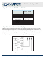
and bill of materials are available upon request. PT, CBT, and CST series LEDs are built in the common anode configuration. To enable driving
these LEDs, the driver circuit, based on National Semiconductor’s LM3433 IC, is configured in the grounded common anode topology (refer
Appendix B), which enables anodes of multiple LEDs to be in electrical contact with each other without necessitating electrical isolation.
Further design support for the driver can be obtained at http://www.national.com.
2.1 Heat-Sink and Driver Board
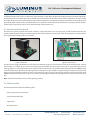
The heat sink, measuring only 40 mm x 40 mm x 40 mm is a high performance, low cost, compact air cooled aluminum extrusion, and
enables significant power dissipation to the ambient by virtue of its low thermal resistance (0.6 º C/W ). The bolt pattern on the front allows
for easy mounting of all CBT and PT series modules.
Figure 2: Heat sink
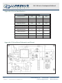
Figure 3: Driver board
The driver board, designed with National Semiconductor’s LM3433 IC (Figure 3), is mounted close to the heat-sink allowing for minimal
cable lengths (<3”) which help prevent current ringing when pulsing LEDs. The driver board, because of its grounded common anode
topology, requires a -12 V DC input with respect to ground and can provide up to 14 A to LEDs in either CW or pulsed mode. PWM dimming
is achieved with a 0-5 V signal from a function generator and frequencies up to 40 kHz are supported. Figure 3 depicts the layout of the
driver board along with the commonly used pins and readouts. The signal pins are used to achieve external current control and provide
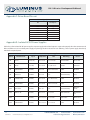
PWM dimming; the orientation of these pins is also shown, starting with pin 1(GND) on the left. Appendix C lists the pin-out for the signal
pins.
Note: The heat sink conducts power even though it is grounded.
2.2 Cable Assembly
Each development kit includes the following cables:
• Power supply to driver board cable
• Driver board to LED cables
• Signal cable
• Thermistor cable
3
960017 Rev C
© 2013 Luminus Devices, Inc. - All Rights Reserved
Luminus Devices, Inc. • T 978.528.8000 • www.luminus.com
1100 Technology Park Drive • Billerica, MA 01821