1
DK-114N series - Development Kit Manual
4. To modulate the LEDs through PWM, connect the 0-5 V pulsed output of a waveform generator across the PWM and GND pins on
the signal cable, with the PWM pin at a positive voltage with respect to GND. 5 V represents Off and 0 V represents On. The Analog
ADJ and POT pins must be shorted; this allows for the LED’s peak current to be controlled via the on-board POT. Proper operation is
best monitored by using a photo detector to observe the light output from the LED. Note: Exceeding 5 V on the PWM pin may cause
permanent damage to the driver board.
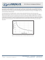
5. Coreboard temperature of the Big Chip LEDs is monitored using a Murata Manufacturing Co. thermistor (part number
NCP15XH103J03RC). When using the short 8-pin cable, the on board thermistor is connected to test points THRM1 and THRM2 on
the driver board. Signal Pins 7 and 8 are also thermistor test points and are equivalent to THRM2 and THRM1. Figure 13 shows the
relationship between the thermistor (coreboard) temperature and the resistance between the thermistor test points. Note that there
is a temperature rise from the thermistor to the LED junction; for guidance on estimating the LED junction temperature (Tj), refer to
appropriate product datasheets. To monitor coreboard temperature when using the two pin driver board to LED cable, the thermistor
cable (Fig 7) must be connected to the on board thermistor. The resistance across the cable’s leads can then be used to monitor
temperature.
Figure 13: Coreboard temperature as a function of thermistor resistance
8
960017 Rev C
© 2013 Luminus Devices, Inc. - All Rights Reserved
Luminus Devices, Inc. • T 978.528.8000 • www.luminus.com
1100 Technology Park Drive • Billerica, MA 01821