1
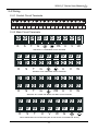
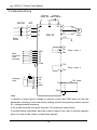
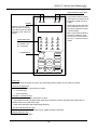
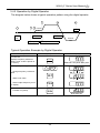
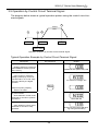
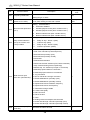
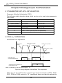
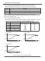
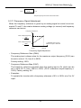
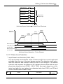
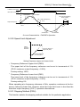
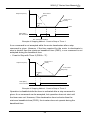
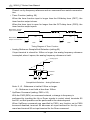
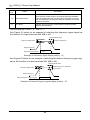
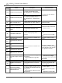
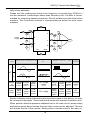
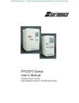
WIN-9_F Series User Manual
Control Circuit Terminal S5 (UP command)
Closed
Open
Open
Closed
Control Circuit Terminal S6 (DOWN command)
Open
Closed
Open
Closed
Operation Status
Accel
Decel
Hold
Hold
FWD Run
UP Command S5
DOWN Command S6
Upper Limit Speed
Lower Limit Speed
Output Frequency
D H
U
H
D
H
U
H
D
D1 H
U
U1 H
D
D1
H
Frequency Agree Signal
U: Up (accelerating) status
D: Down (decelerating) status
H: Hold (constant speed) status
UI: Up status, with clamping at upper limit speed
DI: Down status, with clamping at lower limit speed
Timing Diagram of UP/DOWN Command Input
Notes:
111 When the UP/DOWN command is selected, the upper limit speed is set regardless of frequency reference.
Upper limit speed = Maximum output frequency (P012) × Frequency reference upper limit (P030) /100
222 The lower limit value is either the analog frequency from control circuit terminals FV or FI, or the frequency reference lower limit (P031), whichever is
larger.
333 When the FWD (REV) run command is input, operation starts at the lower
limit speed without an UP/DOWN command.
444 If the jog frequency reference is input while the drive is running by the UP/
DOWN command, the jog frequency reference has priority.
●●
Loop Test (setting: .26.)
Checks operation in the serial interface circuit. If a fault occurs, the digital operator displays “CE”.
5.3.2 Procedure
●
65
●