1
Cloud Sensor II User’s Manual
Make the pole long enough to keep the sensor head well above any snowdrifts – if you get any. The
connector at the end of the cable will corrode if it is left in a puddle of water, especially if it has power on
it. If the snow drifts as high as the bottom of the sensor head, this can happen.
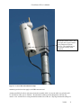
Before leaving the sensor head, please press down gently on the white rain sensor (NOT on the
thermopile window and avoid the anti-bird wires), and make sure that the electronics assembly is fully
seated in the double tube unit. The white disk surface should be about 1/8” or 3 mm. below the edge of
the large white tube. If the electronics assembly moved during shipping, the silicone grease water seal
just under the rain or wetness sensor could have opened up and cause problems during violent rain storms.
9.3 Roof Cable
The cable has been sent to you in a coil without twists in it. To keep it that way you need to cut the two
white cable ties, and then unroll the cable - instead of just holding the bundle and pulling at one end. If
you should ever need to move the cable elsewhere, make sure that you roll it up properly. At one end
make a circle 12” (30 cm) in diameter out of one turn of the cable and tape it. Now “roll” this circle of
cable down the length of the cable gathering it up.
For those who do not already have a convenient hole through an exterior wall for the cable, drill a 15 or
16 mm (5/8”) diameter hole through the wall, making very sure not to drill through any electrical wires or
plumbing pipes. To thread the cable, start with the cable inside. Push a straightened-out metal coat
hanger with the hook at the outside end, from outside to inside. Tape the rectangular connector and 10
cm (4”) of cable to the coat hanger. Pull on the coat hanger. You might need a second person inside to
unroll the cable and to make sure that the cable does not snarl. If you are alone, unroll the cable inside
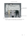
first before pulling it through the wall. Note that the end of the cable with the small rectangular connector
goes to the sensor head.
If you must use a smaller hole (large enough for the cable itself but without the connector), you can
disassemble the rectangular connector using a very small screwdriver and a lot of care. First push the 5
wires into the connector slightly. This disengages the retaining tabs on the clips. Then you depress the
retaining tab of the clip for each pin. They are visible in each of the rectangular small holes on the longer
side. With the retaining tab depressed you gently pull on the wire and the clip will come out.
Before reassembling the connector you might need to use a small knife to bend each retaining tab upward
slightly. The pinout for the rectangular connector is:
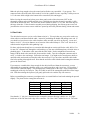
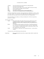
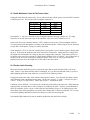
Pin Number
1
2
3
4
5
Twisted Pair
1
1
2
2
Wire
Red
Green
Yellow
Black
Bare
Signal
DataData+
+24V Power
Power Return
Shield
Note that the “1” (for pin 1) molded into the rectangular connector housing is hard to see. It is right
beside one of the side slots at the edge of the connector. Pin 5 has “2695” molded in over it. The same
V0029
30