1
M-Print® PRO
User Manual
Manual Version 2013-02
Content
Introduction
1
About M-Print® PRO ..................................................................................................... 1
About this manual ......................................................................................................... 1
Layout and format ......................................................................................................... 2
Definitions ..................................................................................................................... 2
Installation note ............................................................................................................. 2
General operation
3
Introduction ................................................................................................................... 3
Starting / exiting the program ........................................................................................ 3
User interface ................................................................................................................ 4
Supported file types ...................................................................................................... 5
Commonly used functions ............................................................................................. 6
Editing elements .............................................................................................. 6
Editing layers.................................................................................................. 25
Predefined text sequence .............................................................................. 29
Consecutive numbering ................................................................................. 31
Incrementing and decrementing .................................................................... 38
Color coding ................................................................................................... 40
Synchronizing content .................................................................................... 41
Orders, Order Wizard ..................................................................................... 42
Filter functions ................................................................................................ 43
Licensing ........................................................................................................ 45
Multiple insert ................................................................................................. 46
Inserting a line break ...................................................................................... 46
Excel editing ................................................................................................... 47
Multi-level terminals ....................................................................................... 48
Scales ............................................................................................................ 49
Endless strips ................................................................................................. 56
Document protection ...................................................................................... 62
User interface
65
Introduction ................................................................................................................. 65
Menu bar ..................................................................................................................... 67
File menu ....................................................................................................... 67
Edit menu ....................................................................................................... 69
View menu ..................................................................................................... 71
Insert menu .................................................................................................... 74
Shape menu ................................................................................................... 76
Format menu .................................................................................................. 77
Layout menu .................................................................................................. 78
Tools menu .................................................................................................... 78
Window menu ................................................................................................ 79
User Manual
Content iii
Help menu ...................................................................................................... 79
Toolbars ...................................................................................................................... 80
Standard......................................................................................................... 80
Layout ............................................................................................................ 81
Format Text .................................................................................................... 82
Format Element ............................................................................................. 84
Elements ........................................................................................................ 85
Docking Bars View ......................................................................................... 87
Project Explorer........................................................................................................... 88
Shortcut menu ................................................................................................ 89
Properties window ....................................................................................................... 91
Marker properties ........................................................................................................ 92
Showing properties ........................................................................................ 93
Adjusting properties ....................................................................................... 94
Selecting elements ....................................................................................... 103
Workspace ................................................................................................................ 104
Shortcut menu in the workspace ................................................................. 104
Layers ....................................................................................................................... 105
Layers window ............................................................................................. 106
Layer properties ........................................................................................... 107
Data Grid window ...................................................................................................... 108
Defining the width of the data grid ............................................................... 108
Shortcut menu of the data grid..................................................................... 109
Row height and column width of the data grid ............................................. 109
Info page ................................................................................................................... 110
Getting started
113
Introduction ............................................................................................................... 113
Step 1: Starting the program ..................................................................................... 113
Step 2: Selecting the marker type ............................................................................. 113
Step 3: Captioning the marker .................................................................................. 114
Step 4: Saving the file ............................................................................................... 114
Step 5: Printing the marker type ............................................................................... 115
Step 6: Closing the file .............................................................................................. 115
Managing projects
117
Project structure ........................................................................................................ 117
Changing the project name ....................................................................................... 119
Adding a marker type to a project ............................................................................. 120
Adding a subproject .................................................................................................. 121
Adding a marker type to the subproject .................................................................... 122
Removing a marker type ........................................................................................... 123
Removing a subproject ............................................................................................. 124
Closing the project .................................................................................................... 125
Product catalog
127
Introduction ............................................................................................................... 127
Opening the Product Catalog window ...................................................................... 127
Creating a new product category .............................................................................. 128
Adding a product ....................................................................................................... 128
Removing a product .................................................................................................. 130
Removing all products from a category .................................................................... 130
Removing a product category ................................................................................... 130
Finding a product ...................................................................................................... 131
iv Content
User Manual
Renaming a product .................................................................................................. 132
Templates ................................................................................................................. 132
Resetting the product catalog ................................................................................... 132
Updating the product catalog .................................................................................... 134
Options dialog
137
Introduction ............................................................................................................... 137
Environment .............................................................................................................. 138
General ........................................................................................................ 138
View ............................................................................................................. 141
Program startup ........................................................................................... 142
File extensions ............................................................................................. 142
Directory ....................................................................................................... 143
Administration .............................................................................................. 144
Administration menu .................................................................................... 145
Update.......................................................................................................... 146
Color coding ................................................................................................. 146
Fields ............................................................................................................ 147
Basic settings ............................................................................................... 147
Element defaults ....................................................................................................... 148
Font .............................................................................................................. 148
Elements ...................................................................................................... 149
Plotter ........................................................................................................................ 150
General ........................................................................................................ 150
MultiCard fixture ........................................................................................... 151
SF 4-6 fixture................................................................................................ 151
Pen priming .................................................................................................. 152
PrintJet ADVANCED ................................................................................................. 153
General ........................................................................................................ 153
Service tools................................................................................................. 155
Administration .............................................................................................. 156
PrintJet PRO ............................................................................................................. 157
General ........................................................................................................ 157
Cleaning ....................................................................................................... 157
Current configuration ................................................................................... 158
PrintJet II ................................................................................................................... 159
Cleaning ....................................................................................................... 159
THM Plus S ............................................................................................................... 159
General ........................................................................................................ 159
Opening other file types
161
Opening other file types ............................................................................................ 161
Command line call
163
Introduction ............................................................................................................... 163
Call parameters for exe............................................................................................. 163
Opening or printing a file .............................................................................. 163
Importing or printing a file ............................................................................ 163
Call parameters for converters .................................................................................. 164
Parameters for the QLS converter ............................................................... 164
Parameters for the TNV converter ............................................................... 165
Importing files
User Manual
167
Content v
Introduction ............................................................................................................... 167
Manual import ........................................................................................................... 167
Starting the import ........................................................................................ 167
Step 1: Start page ........................................................................................ 168
Step 2: Filter and import type ....................................................................... 168
Step 3: Selecting the project and variant ..................................................... 170
Steps 4/5: Selecting the data format and field delimiter .............................. 171
Step 6: Options ............................................................................................ 174
Step 7: Field mappings ................................................................................ 176
Step 8: Saving and finishing ........................................................................ 180
Automated import ...................................................................................................... 180
Batch import .............................................................................................................. 182
Creating/adding a batch ............................................................................... 182
Changing a batch ......................................................................................... 183
Converter .................................................................................................................. 183
QLS converter .............................................................................................. 183
TNV converter .............................................................................................. 184
Settings in the Import Wizard ....................................................................... 187
Printing
189
Introduction ............................................................................................................... 189
Calling up the print dialog ......................................................................................... 189
Mapping a printer to a marker type ........................................................................... 191
Printer correction ....................................................................................................... 191
Setting material-dependent slip ................................................................................ 194
Adjusting the printer to the marker type .................................................................... 195
Setting the printer to a print medium ............................................................ 196
Adjusting the printer offset ........................................................................... 196
Setting up print jobs .................................................................................................. 204
Example: ...................................................................................................... 204
Fast printing .............................................................................................................. 206
Printing directly.......................................................................................................... 206
PrintJet ADVANCED Status Monitor ........................................................................ 206
Settings for the PrintJet ADVANCED Status Monitor .................................. 207
Print jobs for the PrintJet ADVANCED ........................................................ 208
Information about the PrintJet ADVANCED ................................................. 209
PrintJet ADVANCED Explorer .................................................................................. 211
Adding a PrintJet Advanced printer ............................................................. 212
Testing a PrintJet Advanced printer ............................................................. 213
Properties of a PrintJet ADVANCED printer ................................................ 213
Activating the plotter
215
Introduction ............................................................................................................... 215
Plot mode .................................................................................................................. 215
Startup options for plot mode ....................................................................... 215
Printing/plotting ......................................................................................................... 216
Selecting the pen and inlay .......................................................................... 216
Changing the marker type............................................................................ 218
Adjusting the pen priming position ............................................................... 219
Mapping a plotter to a marker type ........................................................................... 220
Adjusting the marker type to the plotter ....................................................... 221
Adjusting mapped printers ........................................................................... 223
Symbol Explorer/Plotter Symbol Editor ..................................................................... 224
Editing/creating plotter symbols ................................................................... 225
vi Content
User Manual
Calibration dialog ...................................................................................................... 225
MultiCard fixture ........................................................................................... 225
SF4-6 fixture................................................................................................. 225
Network version
227
Introduction ............................................................................................................... 227
Setup ......................................................................................................................... 229
Sharing folders .......................................................................................................... 237
Tasks to be done on the clients ................................................................................ 239
Setting up client computers.......................................................................... 239
Transferring settings to clients ..................................................................... 240
User Manual
Content vii
Introduction
About M-Print® PRO
The program is used to caption and print labeling materials (MultiCard mats, inserts and labels).
Printable materials are:
MultiCard mats
Sleeve inserts on pages
Labels on pages
Endless labels on rolls
Shrink tubings
MetalliCards
The program has to be installed on a local computer. No server version is available.
About this manual
The manual assumes that you have practical experience of the Microsoft Windows operating
system used by the software.
If you are not familiar with the basics of Windows, please refer to the Windows
user manual.
User Manual
Introduction 1
Layout and format
This user manual applies the following conventions:
Bold Important elements in the program like buttons, menu items, toolbars, names,
etc. are shown in bold.
" " Names of windows and references to other chapters and sections are enclosed
in double quotes.
>
This character separates two successive menu items (e.g. View > Zoom)
This symbol means that the actions which follow must be carried out in the
specified order.
Symbols used
Indicates that this is essential information about M-Print® PRO.
Indicates that this is useful additional information.
Definitions
This section explains the special terms that are used in the M-Print® PRO software.
Marker
A marker is used to identify an electrical or electronic element (terminal, conductor, system,
device, etc.) and also to caption an asset.
Marker type
Marker of a specific type, e.g. MultiCard DEK 5/3,5.
Installation note
2 Introduction
In order to install the program you need administrator rights on the computer
involved.
User Manual
General operation
Introduction
This chapter explains the various ways you can start and exit the program.
You will also find general information about the program structure and the layout of the user
interface.
Starting / exiting the program
Starting the program
Double-click on the icon on your computer desktop.
Exiting M-Print® PRO
Select File > Exit on the menu bar.
If a project is still open, a dialog box appears where you can save the project.
User Manual
General operation 3
User interface
The user interface is where you edit the markers.
It is displayed automatically when you start the program. The user interface contains everything
you need for editing a marker.
The user interface can consist of different elements, depending on the configuration.
You will find more information in chapter "User interface".
4 General operation
User Manual
Supported file types
The following file types are supported when files are opened:
User Manual
M-Print® PRO File (*.mpc)
M-Print® PRO Order File (*.mpo)
M-Print® PRO Template (*.mpt)
M-Print Document (*.abp, *.gdc)
M-Label Document (*.mld)
M-Comm Document (*.tmf)
RailDesigner Export File (*.rde)
TXX/TXY Files (*.txx; *.txy)
Microsoft® Excel® Worksheet (*.xls)
XMT File (*.xmt, *.txt)
General operation 5
Commonly used functions
This section describes the commonly used functions by way of example.
Editing elements
You can create elements by selecting "Insert" from the menu bar or via the "Elements" toolbar
(see chapter "Toolbars").
Before you can edit one or more elements, you first have to select them. (See chapter "Selecting
elements").
See also chapter "Editing options in the Properties window".
When inserting elements or subsequently changing their size, it is possible to retain or change
the symmetry of the elements (see chapter "Symmetry of elements").
Inserting a text field
Create new text field
Click on this toolbar icon or select Insert > Text Field on the menu bar.
Move the mouse to where you want to enter the text.
Create new rounded text field
Same functions as a normal text field. Select Insert > Rounded Text Field.
Use the "Anchor angle" property to determine the start angle of the text.
If the mouse pointer looks like this, you can create a text field.
Press and hold down the left mouse button. Drag the mouse to create a
frame and release the mouse button. An editing field opens where you can
enter text.
You can only enter text in text fields:
if the mouse pointer looks like this, you cannot enter text.
If a text field shows a red triangle when text has been inserted, the text
does not fit into the field. Not all of the text is displayed or printed. In this
case you must shorten the text or reduce the font size (see chapter "Format
menu").
6 General operation
User Manual
Inserting a shape
Create rectangle / square
Click on this icon or select Insert > Rectangle on the menu bar.
Hold down the left mouse button and drag the mouse to create a rectangle.
Use the "Rounding X" or "Rounding Y" property to turn a normal rectangle
into a rounded rectangle.
Create rounded rectangle / rounded square
Click on this icon or select Insert > Rounded Rectangle on the menu bar.
Hold down the left mouse button and drag the mouse to create a rounded
rectangle.
Rounded rectangles only differ from normal rectangles due to the set
"Rounding X" or "Rounding Y" property. If these values are set to 0, a
normal rectangle is displayed.
Draw line
Click on this toolbar icon or select Insert > Line on the menu bar.
Hold down the left mouse button as you draw the line.
Draw circle / ellipse
Click on this icon or select Insert > Ellipse on the menu bar.
Hold down the left mouse button and drag the mouse to create an ellipse.
You can set the exact size and position in the "Properties" window (see
section "Properties window").
User Manual
General operation 7
Inserting an image
The program supports the image formats BMP, EMF, GIF ICO, JPG, PNG, WMF and TIFF.
Insert image
Click on this icon select Insert > Image or on the menu bar.
Hold down the left mouse button and drag the mouse to create a frame. A
selection dialog appears where you can select the image file and open it by
clicking on the Open button. The selected image is inserted.
In the "Properties" window you can specify whether you want to keep the
image in its original size or resize it to fit the frame.
Images are not embedded in the field. The field only contains a link to the
file. The path is displayed in the "Properties" window (see section
"Properties window").
Inserting a barcode
The program supports the following barcode types:
-
Code 39
Code 128
Code 2/5 Industrial
Code 2/5 Interleaved
EAN13
EAN8
EAN128
UPC-A
UPC-E
QR-Code
DataMatrix
Inserting a barcode
Or select Insert > Barcode on the menu bar.
A drop-down field shows the barcodes that can be selected.
Drag the mouse to create an area and release the mouse button. The
selected barcode is inserted.
In the "Properties" window you can enter the numeric or alphanumeric code
(see section "Properties window").
An internal checksum (e.g. code 128) is calculated for certain barcodes.
This checksum must neither be entered manually nor imported with the
barcode value.
8 General operation
User Manual
Inserting special characters
You can use the character map to select a font and see all characters and special characters
that are available with that font.
To open the character map, select View > Character Map > Font on the menu bar.
Click on the upper arrow to select the font, and on the second arrow to select the language.
Position the cursor where you want the character to appear.
Double-click on the character you want to insert, and it appears in the selected text field.
You can also use the shortcut menu to copy a character from this window:
User Manual
Select the character you want to copy, press the right mouse button and select Copy
Character.
Position the cursor where you want the character to appear (inline editor), press the right
mouse button and select Insert on the shortcut menu.
General operation 9
Inserting symbols
You can select and insert symbols using the Symbol Explorer.
On the menu bar, select View > Symbols to open the Symbol Explorer.
Insert symbol
Click on the symbol you want to insert.
Move the mouse to the field you want to contain the symbol.
Hold down the left mouse button and drag the mouse to create a rectangle. The symbol is
inserted in the field.
You can resize the symbol by clicking on it once and dragging the corners to make the
rectangle larger or smaller.
Alternatively:
Select the field in which you want to insert the symbol.
Double-click on the symbol that you want to insert.
You can adjust the appearance of the symbol via the "Size" property (see
section "Behavior" in chapter "Adjusting properties").
Symbol directory
The drop-down field is preset to the default directory for symbols. For changes to the path, see
chapter "Options dialog", section "Directory".
Searching/filtering the symbol directory
You can enter a string to search for or filter symbol files.
The following options are available:
10 General operation
User Manual
Keyword(s)
Result
If the search field remains empty, the entire content of the selected
directory is displayed.
Symbol00?
A question mark is the wildcard for one character.
The program will find, for example, "Symbol001.bmp" and
"Symbol002.bmp".
Symbol*
An asterisk is the wildcard for any number of characters.
The program will find, for example "Symbol010.bmp" and
"Symbol020.bmp".
To reset the search field, click on
.
Inserting a scale
Straight or rounded scales can be inserted.
Create new scale
Click on these icons on the toolbar or select Insert > Scale or Rounded
Scale on the menu bar.
Drag the mouse to create an area and release the mouse button.
A dialog opens in order to set the key data of the scale.
Select the type of scale and set the values, intervals and captions.
Scale captioning depends solely on the start and end value and the caption interval.
Example 1:
If start value = 0, end value = 8 and caption interval = 2, the following sequence is
generated: 0, 2, 4, 6, 8
Example 2:
If start value = 1, end value = 100 and caption interval = 20, the following sequence is
generated: 1, 21, 41, 61, 81
In this case, the end value 100 is not shown.
The intervals of the tick marks (major / minor interval) always relate to the value range.
Example:
Value range (start / end value) from 0 to 50 and major interval = 10.
6 major tick marks are shown (0, 10, 20, 30, 40, 50).
If caption interval = 10 is additionally selected, each major tick mark is also captioned.
User Manual
General operation 11
Settings dialog
Scale type
Appearance of the grid dimension. The following can be selected:
Linear:
The pattern of the value range is linear.
Logarithmic:
The pattern of the value range is square, i.e. a logarithmic scale is
shown.
Adapted:
The pattern of the value range is defined by reference points. The
pattern between reference points is linear (see chapter
"Reference points").
Start value
Caption at the start of the scale
12 General operation
User Manual
End value
Caption at the end of the scale
Major interval
Interval between the major tick marks (measured at the value range)
Minor interval
Interval between the minor tick marks (measured at the value range)
Start angle (only rounded scale)
Angle at which the rounded scale starts (see also chapter "Rounded scale".
End angle (only rounded scale)
Angle at which the rounded scale ends (see also chapter "Rounded scale".
Interval
Caption interval to the next caption in each case (from the start value)
Example: If start value = 0, end value = 8 and caption interval = 2, the following
sequence is generated: 0, 2, 4, 6, 8
Alignment (only rounded scale)
Appearance of the caption. The following can be selected:
Horizontal:
The caption is shown horizontally
Tangential:
The caption is shown tangentially (in the direction of the circle).
The caption can be rotated by 180° for both alignments.
Scale length or Scale radius
For a straight scale, the length of the inserted scale element.
For a rounded scale, the inner radius of the scale element.
The value is preset when dragging the element with the mouse.
Scale height
The scale height corresponds to the height of the major tick marks.
The value is preset when dragging the element with the mouse.
The minor tick marks are always half as long as the major tick marks.
Font size
The font size of the caption.
The value is preset when dragging the element with the mouse.
You can set the exact size, position and caption of the scale in the "Properties"
window later (see section "Properties window").
For further information and examples, please refer to chapter "Scales".
User Manual
General operation 13
Appearance information
If a scale shows red triangles, the chosen values do not fit into the dimensions of the scale
element. In this case, use the mouse to enlarge the element in the displayed directions.
Snapping elements to the grid
To specify whether you want the elements to snap to the gridlines or not, select View > Grid >
Snap to Grid.
The grid must be visible (Menu View > Grid > Show).
Selecting elements
Select element
After clicking on this icon, you can click on an element to select it.
Select multiple elements
If the elements you want to select are next to each other, you can select
them all in a single action by dragging a frame around them.
Click on this icon to activate the frame to select elements. Press and hold
down the left mouse button. Drag the mouse to create a frame around the
elements you want to select.
14 General operation
User Manual
Moving elements
Elements on the project layer or marker layer can only be moved within the defined project area
or marker area.
Select the element you want to move by left-clicking on it. When you move the mouse
pointer over the element, it changes into the following shape, which means you can move
the element:
Hold down the mouse button and move the element to its new position.
Another way of moving an element is to define settings in the "Properties" window (see section
"Properties window", "Size and position" category. You can enter exact values here.
User Manual
General operation 15
Rotating elements
Click on the element (text, shape, image, barcode) you want to rotate.
Select Shape > Rotate….
The following window appears:
Specify the details of the rotation you want, then confirm by clicking on OK.
Note that, if necessary, the element will adapt to the dimensions of the marker
area when it is rotated.
Example:
This image shows the element before it is rotated:
... and after the rotation:
16 General operation
User Manual
Copying and pasting elements
In the course of copying and pasting, only the document-individual properties can be transferred.
However the properties are only transferred to their full extent if the same element type is
involved (e.g. text on text, image on image).
Click on the element(s) you want to copy.
Select Edit > Copy.
Click on the element that you want to paste into.
Select Edit > Paste to paste the content OR Edit > Paste Elements to paste the element.
Not all elements can be pasted into other elements.
Cutting and pasting elements
Select the element you want to cut.
Select Edit > Cut.
Click on the element that you want to paste into.
Select Edit > Paste to paste the content OR Edit > Paste Elements to paste the element.
Not all elements can be pasted into other elements (see chapter "Copying and
pasting elements").
User Manual
General operation 17
Duplicating elements
Select the element you want to duplicate.
Select Edit > Duplicate.
The duplicated element is placed slightly offset on top of the original element.
Deleting elements
Select the element you want to delete.
Select Edit > Delete.
In the Delete submenu, you have the following items to select from:
Field content
Entire field
Selected
markers
This page
Pages...
Only delete the content of the elements.
Delete the entire field.
The entire markers with the selected elements on them are
deleted without a confirmation prompt.
The currently visible page is deleted.
A dialog opens to delete several pages.
If a menu item is not available (grayed out), the functionality for the selected
situation cannot be used.
18 General operation
User Manual
Locking elements
Text fields, image fields, barcodes and shapes can all be locked.
However, only in locked text fields is it still possible to change the content and formatting.
Among other things, the following properties are locked:
-
Size and position
Border and fill
Field properties
Orientation and tab order
Select the element you want to lock.
Click on this toolbar icon to lock the selected element.
Example of a locked element
Creating square elements
For creating square elements, see chapter "Symmetry of elements"
User Manual
General operation 19
Symmetry of elements
Symmetry of elements can be used to either keep the dimensions (aspect ratio) of the elements
or to set them to the same values (square).
Various options are available:
Inserting while holding down the Shift key (square dimensions)
If you insert the elements while holding down the Shift key, the dimensions remain square.
Exceptions:
Line – is inserted horizontally or vertically
Rounded text field – is always rounded
Scale
Dragging while holding down the Shift+Alt keys (setting square dimensions)
If you drag existing elements (multiple selection possible) at their corners while holding down the
shortcut Shift+Alt, the dimensions are changed quadratically.
Exceptions:
Line – is changed horizontally or vertically
Scale
Dragging while holding down the Shift+Ctrl keys (keeping proportions)
If existing elements (multiple selection possible) are dragged at a corner while holding down the
shortcut Shift+Ctrl, the proportions of the dimensions are kept. The aspect ratio is not changed.
Exceptions:
Line – retains its angle
Scale
20 General operation
User Manual
Changing the order of elements
If a number of elements are arranged on top of each other, you can use the "Layout" toolbar to
change the order of the elements.
The following settings apply to the selected element in the current layer.
The element is moved one layer forward.
The element is moved one layer back.
The element is brought to the front.
The element is sent to the back.
Select the element you want to move, then click on the relevant icon.
You can also access these functions from the menu bar by selecting Shape and then the
required layer setting.
Resizing elements
Click on the element you want to resize.
Drag the corners to make the element larger or smaller.
You can specify the exact dimensions in the "Size and position" category in the "Properties"
window.
See section "Properties window".
User Manual
General operation 21
Setting the same height
Select the elements whose height you want to change, then click on this icon.
To adjust the height, select Shape > Same Height on the menu bar.
Setting the same width
Select the elements whose width you want to change, then click on this icon.
To adjust the height, select Shape > Same Width on the menu bar.
Saving an image in a file
If you want to save all images embedded in the program file (e.g. for transferring the file), select
File > Embed Image and Save As... and save the file under a different name.
All images are integrated/embedded in the file.
To save images embedded in files externally again, see chapter "Transferring an image from a
file")
Transferring an image from a file
Images can be integrated in the program files (see chapter "Adjusting properties – Content").
The "Type" property of the image is set to the "integrated" value.
Proceed as follows to subsequently transfer these images from the file:
Right-click on the integrated image.
Select Save as Image... in the shortcut menu that opens.
Select the path and image name and click on Save.
22 General operation
User Manual
Grouping
Several (at least two) elements of a marker can be grouped.
Select the elements to be grouped and select Edit -> Group.
It is possible to compile groups in further groups.
Changes to certain properties have an effect on the whole group (e.g. line thickness, fill color).
The group is selected via the first click on a group element. A further click on an element selects
the element in the group, allowing its properties to be changed (e.g. its text).
When a group is ungrouped, any groups within it are preserved.
Only elements of the same field type can be grouped (see also chapter "Field").
Selected elements within a group can be deleted from the group.
Moving a group with the mouse
A group can only be moved with the mouse at its outer limits. The mouse pointer changes
accordingly.
Overview of existing groups
An overview of the existing groups is displayed in the object selection. A group can also be
selected via this view (see chapter "Selecting elements").
Formatting text
You can format text and set lines using the "Format Text" toolbar or the "Properties window".
Aligning text
To align text, select it and click the relevant icon in the "Format Text" toolbar.
User Manual
General operation 23
Changing the barcode type
In the "Properties" window you can select a barcode type in the "Content" category (see also
section "Content" in chapter "Properties window").
Select the desired barcode type in the field "Type".
Next, in the "Text preview" field, you can enter the numeric or alphanumeric code, depending
on the barcode type.
Certain barcodes have further properties which can be selected (e.g. size or ECC level for
the error correction value).
24 General operation
User Manual
Editing layers
The pages of a marker type are organized into layers.
The individual layers are edited in the "Layers" window.
To show or hide the layers, select View > Layers on the menu bar.
Double-click on the layer you want to change (e.g. "Marker layer") to open the "Layer
Properties" window.
Changing the layer name
You can change the layer name via the "Layer Properties" dialog box (see chapter "Editing
layers").
Enter the new name in the "Layer name" field and confirm your input by clicking on OK.
The new name applies to this file.
User Manual
General operation 25
Changing the layer color
You can change the colors of layers in the "Layer Properties" window. To open it, double-click
the name of the layer you want to change (see chapter "Editing layers").
Click on the arrow in the relevant field to change the border and fill color. You can select a
color from the drop-down field.
You can click on the Other... button for advanced color selection options.
Here you can select a standard color or create a custom color.
Hiding a layer
To disable a layer so that it is no longer visible, click on the eye icon:
Layers not showing this icon will not be displayed.
You can display the layer by clicking the box again.
26 General operation
User Manual
Not printing a layer
If you do not want to print a layer, click on the printer icon:
Layers not showing this icon will not be printed.
Adding a free layer
Unlike the other layers, free layers can be duplicated.
Click on the following icon in the "Layers" window to add a new free layer.
If you click on the icon again, another free layer is added.
Removing a free layer
In the "Layers" window, click on the free layer you want to remove. Click on this icon:
You can remove all free layers except for one, which must always be present.
User Manual
General operation 27
Moving a free layer to another position
If you have created a number of free layers, you can move them in relation to each other, i.e. you
can change the order of layers on top of each other.
The "Layers" window has the following icons:
Moves the layer up one layer.
Moves the layer down one layer.
Select the free layer you want to move and click on the relevant button.
Reducing free layers to a single layer
Click on this icon to reduce all free layers to a single layer:
You cannot select individual layers and reduce them. It is only possible to
reduce all free layers to a single layer.
Reduction to one layer cannot be undone!
Locking layers
You can lock specific layers to prevent the elements on them from being edited. Even text cannot
be changed on a locked layer.
Click on the layer you want to lock.
In the "Layers" window, click inside the third column for the layer.
The following icon appears.
The layer is now locked and cannot be edited.
You can remove the lock by clicking on the field again.
28 General operation
User Manual
Predefined text sequence
Defining a predefined text sequence
Follow these steps to define a text sequence:
Open a marker type and insert the text to be saved (e.g. A 1 to A 10) into a text element.
Select the text that you want to save as a text sequence.
Select Tools > Predefined Text Sequence….
Give the text sequence a revealing name.
Click on Add and then on Save.
To insert a predefined text sequence, see section "Inserting a predefined text sequence".
User Manual
General operation 29
Inserting a predefined text sequence
Follow these steps to insert a predefined text sequence (see "Defining a predefined text
sequence"):
Open a marker type and select the element after which you want to insert the predefined text
sequence.
Open Insert > Predefined Text Sequence….
Select the required sequence and the number of inserts.
Click on Insert.
Here, the predefined text sequence was inserted three times:
30 General operation
User Manual
Consecutive numbering
Introduction
With the "Consecutive Numbering" function you can add consecutive numbers to marker types.
Only document-individual fields can be captioned with the Auto Fill function (see
chapter "Properties window").
Select the field or an area where you want the caption to appear.
Select Insert > Consecutive Numbering….
The window for consecutive numbering opens up.
Consecutive Numbering window
User Manual
General operation 31
The window has the following buttons:
Click on the OK button to confirm your inputs.
Click on the Cancel button to cancel the process.
Click on the Help button to load the Help.
Click on the Last Sequence button to load the last sequence
used.
Click on the Reset to Default button to restore the
predefined default values.
In the "System" group, select the notation you want to use for numbering.
Decimal
This uses the decimal system, i.e. the ten digits from 0 to 9, then 10, 11, 12, etc.
PLC / Octal
Choose this option to set a PLC-specific caption format. The PLC caption format usually includes
two counters, separated by a period (e.g. 4.0).
Counter Y uses the octal system from 0 to 7, and block counter X uses the start value in the
"Block" field in conjunction with the block step. The "Prefix" field usually contains a letter (e.g. I
for Input), and a suffix can also be defined (see example 2).
Hexadecimal
This notation is based on the hexadecimal system, which uses the characters 0 to 9, A, B, C, D,
E, F.
Example: 0, 1, ….9, A, B, C, D, E, F, 10, 11, …,18, 19, 1A, 1B, 1C, 1D, 1E, 1F, 20, … 29, 2A, …
2F, 30, … etc.
Alphanumeric
Three numbering sequences are possible with this option: a to z or A to Z or 0 to 9.
Example: b to m (only one character is allowed, not AA to ZZ for example).
Character string
The same word is written to all the text fields, e.g. "ISB". Character strings: 1234 or ABCD or
1a2Bd3.
32 General operation
User Manual
In the "Input" group, enter the following values:
Start value and End value
Numbering can be in ascending or descending order.
The values to which the "Start value" and "End value" fields are automatically set depend on the
number of fields selected.
Prefix
You can prefix one or more alphanumeric characters to the counted value. (e.g. Conductor or C
or 2004-)
Suffix
You can append one or more alphanumeric characters to the counted value (e.g. left or X).
Block
This software defines a block as an additional counter inserted between the prefix and the start
value.
The "Options" group is where you make the following settings:
Step
Here you define the value by which the start value will be incremented/decremented.
Examples:
If start value = 1, end value = 20 and step = 3, the following sequence of numbers is generated:
1, 4, 7, 10, 13, 16, 19
If start value = 8, end value = 2 and step = 2, the following sequence is generated: 8, 6, 4, 2
If start value = A, end value = K and step = 2, the following sequence is generated:
A, C, E, G, I, K
Block step
Here you define the value by which you want to increment the block, e.g. block = 0 and block
step = 2. Example: 0, 2, 4, 6….
Duplicating each value
Here you specify how many times you want to duplicate each value.
If you enter the value 2 in the field, the following sequence is generated for numbering from 1 to
5: 1, 1, 2, 2, 3, 3, 4, 4, 5, 5.
User Manual
General operation 33
Duplicating a sequence
Here you specify how many times the sequence (the value between start and end) will be
needed.
Skip markers
Here you specify the number of captioned fields you want to skip.
Example: Start value = 1, end value = 5, skip = 3
Insert sequence
Click on the check box to activate or deactivate this function.
If the fields you are captioning already contain text, you can specify where you want the text to
appear. Select the relevant radio button:
Before existing text
After existing text
If you do not activate this function, the entire content of the marker will be overwritten.
Project fields
Click on the check box to activate or deactivate this function.
This option enables you to automatically number project fields. The start value can be entered in
the "Number" field (there is NO consecutive numbering if the "Number" field is deleted). You may
also enter a "Prefix" or a "Suffix".
34 General operation
User Manual
Formatted sequence
In the left field, enter the format for the block counter and, in the right field, enter the format for
the numbering sequence defined by the start value and end value.
The following formatting options can be used for the block and the numbering sequence. The
block format is only applied if the "Block" field contains an entry.
#.00
$#.00
#,###.00
0%
The numbers are formatted to two decimal places. For the number
sequence 1 to 3, this produces the following formatted numbers:
1.00 then 2.00 then 3.00, etc.
A constant appears before the number (the dollar sign in this example).
Formats the number sequence 1000 to 2000 as follows: 1,000.00 then
1,001.00 then 1,002.00, etc.
Formats the number sequence 1 to 5 as 100%, 200%, .., 500%
(percentage).
Preview
The first captioned field is displayed here.
Automatic recognition of field content
The Auto Fill function attempts to identify the text of the first selected field so it can put
appropriate default settings in the "Consecutive Numbering" window.
For example, if you enter A4.0X in a text field, the system recognizes that A is the prefix, X is the
suffix, the block counter is 4 and the start value is 0.
User Manual
General operation 35
Example 1
We want to caption a MultiCard as follows:
The start value will be 1 and the end value will be 3. There will be a block in front of the value,
counting from 0. Each number (block plus start value) will be preceded by a P and concluded by
an S. One field will be skipped, i.e. there will be an empty field between the captioned fields.
Each field will appear twice in succession. The values of the block entry will start at 0 and be
incremented by 2, i.e. 0, 2, 4, 6.
Result:
36 General operation
User Manual
Example 2
PLC captioning format
The relays 4, 5 and 6 are to be captioned. Each of these relays has five inputs (= I), to be
numbered from 0 to 4. Numbering is required to begin at I4.0 up to I4.4, then I5.0 to I5.4 and
finally I6.0 to I6.4.
Result:
User Manual
General operation 37
Incrementing and decrementing
Instead of consecutive numbering, numeric values can also be incremented and decremented
via a function.
Two options are available
Automatic recognition of the numeric value by selecting two text fields, see ("Automatic
recognition of numeric value")
Continuation of the numeric value with a default value (see "Continuing the numeric value
with a default value")
There is pattern recognition which only considers the numeric values of one text.
Example: After incrementing, "A-10x" becomes "A-11x"
Any negative sign for a number is interpreted as a text character and is not
taken into consideration.
The "Increment Value" and "Decrement Value" functions always fill the next text
field. If there are several text fields on one marker, they are filled one after the
other.
The step of the function can be set via the options (see chapter "Basic settings").
38 General operation
User Manual
Automatic recognition of the numeric value
If you select two text fields with numbers, the difference between the figures in the two fields is
used as the value.
Follow these steps:
Select at least two text fields with numeric values.
Select Insert > Increment Value or Insert > Decrement Value
Example:
Selecting text fields
Incrementing values twice
Continuing the numeric value with a default value
If you only select one text field with a number, a preset value is used for incrementing and
decrementing. The respective step can be set via the options dialog (see chapter "Basic
settings").
Follow these steps:
User Manual
Select a text field with a numeric value.
Select Insert > Increment Value or Insert > Decrement Value.
General operation 39
Color coding
The background and font colors of the numbers 0 to 9 can be set via the color coding option.
The settings for the background and font color are set via the options menu (see section "Color
coding" in chapter "Options dialog").
Color coding can only be used in single-lined text!
The color coding is applied to complete elements (not to parts of the text).
The color coding settings are saved in the project file (e. g. *.mpc).
This enables you to create different files with different color codings.
If the color codings defined in the program differ from the ones defined in the project, the
following message box appears:
Click on Yes to accept the color values defined in the program.
Click on No to keep the color values defined in the project.
40 General operation
User Manual
Synchronizing content
Text elements can be linked to other text elements (so-called data sources).
Follow these steps:
Click on the text elements to which you want to assign a data source (e. g. TEXT FIELD 2).
Open the "Properties" window (see chapter "Properties window")
Enter the field name of the data source in the "Data Source" field (e. g. TEXT FIELD 1).
Select Edit > Synchronize Content.
The content of TEXT FIELD 1 is transferred to TEXT FIELD 2.
User Manual
General operation 41
Orders, Order Wizard
The Order Wizard enables you to order marker types from the currently open project by e-mail.
To open the Order Wizard, select Tools > Order… from the menu bar. .
Select Tools > Order....
Make the settings on the tabs.
Save as Default
The settings of the active tab are saved as defaults.
The delivery address stated in the order must be in the ordering party's country.
42 General operation
User Manual
Filter functions
Filtering in fields
You can use the filter to view elements with special phrases.
Select View > Filter > Filter... to show the filter dialog.
Example:
Before the
filter:
Filter setting:
Result:
User Manual
General operation 43
Filter overflow
You can show fields with text overflow via View > Filter > Filter Overflow.
The font size can be narrowed or shortened for these fields.
44 General operation
User Manual
Licensing
With the licensed version you have the unrestricted rights for using the program according to the
software key.
To license the program, select Help > License Key... from the menu bar .
First select the license key you have, then follow the further instructions.
User Manual
General operation 45
Multiple insert
You can insert multiple text fields, barcodes and images from the clipboard.
Select Edit > Multiple Insert... for multiple insertion .
Inserting a line break
This function allows line breaks to be inserted subsequently in the content of text fields.
To do this, select Edit > Insert Line Break... from the menu bar.
46 General operation
User Manual
Excel editing
The content of existing text fields can also be edited in Excel.
Select Edit > Start Excel Editing.
In Excel you can then edit the text content and all supported formats of the text fields.
Close Excel or select Edit > Exit Excel Editing in the program to transfer the content to the
application.
User Manual
General operation 47
Multi-level terminals
You can use this function to resort selected data with a predefined step.
Select Edit > Multi-level Terminal.
If no markers are selected, sorting will be effected using all markers.
Example:
Default values:
48 General operation
Multi-level terminal selection 2
= Two-tier terminal
Sorting: 1,3,5,7,9
then 2,4,6,8
Multi-level terminal selection
3 = Three-way terminal
Sorting: 1,4,7,10
then 2,5,8
then 3,6,9
User Manual
Scales
Scales and rounded scales can be inserted as new elements (see chapter "Inserting a scale".
The start and end values determine the value range of the scale. The intervals of the tick marks
(major / minor interval) always relate to the value range.
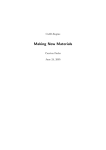
Scale properties
Scales are characterized by the following properties:
1
2
3
Scale zero-point (scale zero-point left, scale zero-point top)
Scale length
Scale height
The scale height corresponds to the height of the major tick marks.
4 Start value (start and end values determine the value range of the scale.)
5 End value
6 Major tick mark
7 Minor tick mark
8 Interval of the major tick mark (major interval)
9 Interval of the minor tick mark (minor interval)
10 Caption interval
User Manual
General operation 49
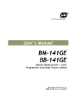
1
2
3
4
Scale zero-point (scale center left, scale center top)
Start angle (see also chapter "Rounded scale")
End angle
Scale height
The scale height corresponds to the height of the major tick marks.
5 Start value (start and end values determine the value range of the scale.)
6 End value
7 Major tick mark
8 Minor tick mark
9 Interval of the major tick mark (major interval)
10 Interval of the minor tick mark (minor interval)
11 Caption interval
A further explanation of the properties can be found in chapter "Inserting a scale".
50 General operation
User Manual
Rounded Scale
The base line of a rounded scale is a circular arc.
The scale is arranged clockwise along the circular arc. The zero-point is at the top.
Tangential captioning causes the scale captions to be arranged tangentially to the base line (see
"Example 1" in chapter "Scale examples").
Reference Points
The value pattern of a scale can also be defined by reference points.
A reference point indicates the exact position of a value on the scale.
The value pattern is linear between the reference points.
Add reference point
Adds a new reference point in the dialog.
User Manual
General operation 51
Delete reference point
Deletes the selected reference point.
Interval
The interval of the reference point from the start of the scale.
Value
Caption value of the reference point. Whether the caption value is
displayed or not depends on the selected caption interval of the scale.
With a straight scale, the value should be in the visible range of the
element. With a rounded scale, it should be between the start angle and
the end angle.
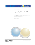
Example:
The upper scale does not contain reference points.
For the lower scale, a reference point with the value 4 has been defined at an interval of 10 mm.
At the selected caption interval of 2, the reference point is also captioned. The area before and
after the reference point is also divided in a linear manner.
52 General operation
User Manual
Scale examples
Example 1:
The illustration shows a round scale with the following properties:
Scale radius
Start angle
End angle
Scale center left
Scale center top
Scale height
Caption orientation
Start value
End value
Value distribution
Major tick mark
Minor tick mark
Caption interval
Font size
User Manual
5 mm
225 (or -135)
135
10 mm
10 mm
0.8 mm
Tangential
0
100
Linear
10
2
20
3
General operation 53
Example 2:
The illustration shows a scale with a linear value pattern and the following properties:
Scale length
Scale zero-point left
Scale zero-point top
Scale height
Start value
End value
Value distribution
Major tick mark
Minor tick mark
Caption interval
Font size
54 General operation
20 mm
2 mm
5 mm
1.5 mm
0
100
Linear
10
2
20
4
User Manual
Example 3:
The illustration shows a scale with a logarithmic value pattern and the following properties:
Scale length
Scale zero-point left
Scale zero-point top
Scale height
Start value
End value
Value distribution
Major tick mark
Minor tick mark
Caption interval
Basis of the logarithmic scale
Font size
User Manual
20 mm
2 mm
5 mm
1.5 mm
2
100
Logarithmic
Automatic
Automatic
Automatic
2
3
General operation 55
Endless strips
Endless strips are rolled goods, i.e. endless material that can be printed from one side.
Compared to other marker types, it is the user who determines the appearance of the layout.
To insert an endless strip, select the corresponding marker from the product catalog.
A basic dialog or an extended dialog opens, depending the marker that is opened.
56 General operation
User Manual
The following can be displayed, depending on the marker:
Number of elements / Width of each element
The number of elements multiplied by the width of each element determines the total
element length.
End plate
As the strip is cut off, it may be necessary to leave a small space for the cutting loss.
Strip height
The strip height is specified by the selected product from the product catalog.
Total element length
Display of the total length (number of elements x width of each element)
Marker length
The length of the marker on the strip. It is specified by the total length of the elements
plus the end plate.
Number of rows
Number of rows for each marker.
Between 1 and 3 rows are usually used, as the height of the strip is limited. The total
height of all the rows should not be greater than the height of the strip.
Same row height
The row heights are calculated automatically.
Row…
Row on the marker.
Fields
Number of fields (e.g. text fields) which should be displayed in the row.
Height
The height of the row.
The total height of all the rows should not be greater than the height of the strip.
Element type
The following can be selected:
Text element:
The row consists of text elements that can be captioned
Connector
Graphic connector object
Paste
Inserts the selected settings as a marker. Further markers can be inserted as long as
the dialog is not closed.
Newly inserted markers are added to the end of the strip.
Connector
There are the following graphic connector elements, which can be adjusted via the "Properties"
window:
Type: Start
User Manual
General operation 57
Type: Junction
Type: T-Junction
Type: End
58 General operation
User Manual
Examples of endless strips
Three different marker settings are added to an endless strip in the example.
Setting 1:
Result 1:
User Manual
General operation 59
Setting 2:
Result 2:
60 General operation
User Manual
Setting 3:
Result 3:
User Manual
General operation 61
Document protection
The document protection feature lets you protect the layout of your project file against changes.
Consequently only the content can be changed – like with a form.
Note the following document protection properties:
Applies to all elements for which the "Locked" property has been set (see chapter "User
interface", section "Behavior").
Protects the "Locked", "Printable" and "Read only" properties, among other things.
Prevents the deletion, moving and addition of elements.
Document protection settings
The following settings, among others, can be made by selecting "Tools -> Document
Protection Settings…" from the menu bar:
Current Password:
The current password has to be entered in order to change the password or remove
document protection.
Set Document Protection
You can define a new password for document protection here.
The previous password is overwritten.
Remove Document Protection
You can remove existing document protection here. The current password has to be
entered.
62 General operation
User Manual
Enabling document protection
Follow these steps to enable document protection:
Create a project file and set the "Locked" property to "Yes" for all fields that need to be
protected (see chapter "User interface", section "Behavior").
Select Tools -> Document Protection Settings… from the menu bar or click on the
icon.
If no password has been assigned yet, the document protection settings dialog opens.
Type in a new password and click on OK.
Document protection has now been enabled.
That document protection has been enabled is shown
on the toolbar by the Enabled icon (
)
and after the version number (see chapter "User interface", section "Introduction".
Disabling document protection
Follow these steps to disable document protection:
Open a protected project file.
Select Tools -> Document Protection Settings… from the menu bar or click on the
icon.
A dialog opens, requesting the password.
When the password has been entered, document protection is disabled until the project file is
closed again.
User Manual
General operation 63
Removing document protection
Follow these steps to remove document protection:
Open a protected project file.
Select Tools -> Document Protection Settings… from the menu bar or click on the
icon.
The document protection settings dialog opens.
Type in the current password, select "Remove Document Protection" and click on OK.
Document protection has now been disabled.
64 General operation
User Manual
User interface
Introduction
The user interface can consist of different elements, depending on the configuration.
User Manual
1
Menu bar
The menu bar enables you to use the most important program functions.
Menu items can be active or inactive.
2
Toolbars
You can use the toolbar icons to execute important commands.
The toolbars are movable and dockable.
3
Tabs
Tabs are arranged below the toolbars.
If you click on a tab, the associated marker type moves to the foreground.
4
Ruler
There are rulers along the top and the left of the workspace. You can use the
rulers to measure distances and spacing.
5
Project Explorer
User interface 65
The default position of the Project Explorer is on the left of the user interface.
The Project Explorer has a hierarchical structure and is used for managing
projects (see section "Project Explorer").
6
Properties window
In the "Properties" window you can display and change the properties of various
elements, such as text fields, images or barcodes (see chapter "Properties
window").
7
Workspace
The workspace occupies the right of the user interface.
Here you can view and edit the currently selected marker type.
8
Data grid
The data grid is used to show and edit the content of the marker elements "text
field" and "barcode" in tabular form.
(See chapter "Data grid").
9
Status bar
The status bar runs along the bottom of the user interface.
The following items are shown:
Active layer (e.g. marker layer, free layer, etc.)
Number of available markers, columns, lines of the active layer
Position of the cursor along the X and Y axes and the unit of length (e.g.
mm)
Status of the CAP, NUM and SCRL functions
Active functions are shown in black.
10 Version number
Display of the current program version.
11 Marker areas
Printable areas on the marker types.
By default, each marker area (short: marker) has a document-individual text
element (see section "Field").
The marker areas are arranged on the marker layer.
12 Project layer
By default, the project layer has a document-individual text element, the so-called
project marker.
Elements
Text fields, shapes (lines, rectangles, ellipses, scales), images and barcodes are all referred to
as "elements".
66 User interface
User Manual
Menu bar
This section describes the most important functions of the individual menus.
File menu
New
You can use this menu item to create a new file.
Open
Opens an existing file. The specification of a file name can be set via the options dialog (see
chapter "Options dialog", section "Environment", section "General").
Save
Saves a file you have been working on.
Save As…
Lets you specify a new name when you save a file.
Embed Images and Save As
Embed images available in the program file and save under the file name.
Close
Closes a file.
Import…
You can use this menu item to import data from other formats.
Batch Import
You can import external data via a script.
User Manual
User interface 67
Print…
This menu item displays the dialog box for printing marker types.
Toggle Plot Mode
Switches to plot mode (see section "Plot mode").
Adjust Marker Type…
Adjusts the marker type (see section "Adjusting the printer offset").
Send to…
This menu item enables you to send your current project by e-mail.
Recent Files
This part of the menu lists recently opened files.
Exit
You can use this menu item to exit M-Print PRO.
68 User interface
User Manual
Edit menu
Undo
This undoes the last editing step.
Redo
Redoes the steps that have been undone. Redoing relates to the basic functions and cannot be
undone again
Cut
This menu item cuts one or several selected elements.
Copy
This menu item copies one or several selected elements.
User Manual
User interface 69
Paste
This menu item pastes the clipboard content into a selected field.
Paste Elements
This menu item pastes a copied element into a selected field (e.g. a symbol).
Multiple insert
Inserts a copied element multiple times (see section "Multiple insert").
Duplicate
This menu item duplicates a selected element and places it (slightly offset) on top of the original
element.
Grouping
Groups the selected elements (or groups) as a new group (see section "Grouping").
Ungroup
Ungroups the selected group.
Start Excel Editing
This menu item starts Excel editing (see section "Excel editing").
Exit Excel editing
This menu item ends Excel editing.
Find
Calls the search dialog. The current marker is checked for the entered search criterion.
It is possible to search in several rows.
Replace
Opens the search/replace dialog.
The current marker is checked for the entered search criterion.
It is possible to search and replace in several rows.
Inserting a line break
Opens a dialog to insert line breaks (see section "Inserting a line break").
Synchronize content
Synchronizes all fields for which data sources exist (see section "Synchronizing content").
Select
This menu item gives you several options for selecting elements (e.g. All fields (current page) or
All fields (all pages)).
Delete
This menu item gives you several options for deleting elements (e.g. text field, etc.).
Change Marker Type…
This menu item enables you to change the marker type.
The content is transferred (if possible).
Delete Marker Type
This menu item enables you to delete the marker type.
Format Painter
You can use this function to copy the formatting, font, color, etc. to another element.
70 User interface
User Manual
Sort markers
Opens the sort dialog. Here, you can sort the markers by various sort criteria.
Flip Markers
This function enables you to flip the order of the selected markers.
Multi-level Terminal...
Opens the multi-level terminal dialog.
You can use this function to resort selected data with a predefined step (see chapter "Multi-level
terminals").
View menu
Toolbars
This menu item contains the following submenu items.
Standard
The "Standard" toolbar cannot be disabled.
Layout
To position elements (e.g. rotating, alignment)
Format Text
Contains text formatting functions like font and font size, color, etc.
Format Element
Contains the functions for formatting text elements such as
User Manual
User interface 71
line thickness or fill color.
Element
Selection box for inserting all available elements, such as text fields, images and barcodes.
Docking Bars View
This opens a window in which you can show or hide the various editing windows such as
"Properties" and "Layers" and the Project Explorer.
Header Line
This option shows/hides the title bar showing the application name and version.
Customize...
This shows a dialog box in which you can change the way the toolbar icons are displayed on
screen, or even create new toolbars.
Project
Showing or hiding the Project Explorer.
Layers
Showing or hiding the "Layers" window.
Properties
Showing or hiding the "Properties" window.
Character Map
Showing or hiding the "Character Map" window.
Symbols
Showing or hiding the "Symbol" window.
Data grid
Showing or hiding the data grid.
This table is used for data entry. The data is shown simultaneously on the markers (see chapter
"Data grid").
Filter
Filters your current marker according to certain criteria so that only the filtered result is shown
(see section "Filter functions").
Status bar
Showing or hiding the status bar.
Show Start Page
Showing or hiding the start page in the workspace.
Reset to Default
Resets all changed settings to default.
Zoom
This menu item contains the following submenu items.
Maximize
Maximize the drawing area display
Minimize
72 User interface
User Manual
Minimize the drawing area display
Original size
Reset the size of the drawing area display
Document Field Selection
When a marker is selected, all marker fields are selected.
Grid
This menu item contains the following submenu items.
Show
This option places gridlines over the marker type
You can use the gridlines to help you align the elements
(see chapter "Snapping elements to the grid").
Snap to Grid
Here you specify whether you want elements to snap to the gridlines.
Toggle orientation
In the rotated view, all elements are shown rotated by 90°. The elements (e.g. barcode or text)
can still be edited in WYSIWYG mode in the rotated view.
The rotated view is possible for all marker types that are NOT "endless".
User Manual
User interface 73
Insert menu
Marker Type...
You can insert a new marker type via this shortcut menu item. The product catalog is shown for
selection.
New Page
Adds a new page for the current marker type.
Markers…
Adds a selectable number of markers to the marker type.
To insert endless strips, see chapter "Endless strips".
Increment Value
The numeric value of a marker/text element is incremented and inserted in the next marker/text
element.
The previous content of the target text field is overwritten!
Decrement Value
The numeric value of a marker/text element is decremented and inserted in the next marker/text
element.
The previous content of the target text field is overwritten!
74 User interface
User Manual
The value is only decremented in the positive number range!
Consecutive Numbering...
This menu item allows you to number the markers automatically (see chapter "Consecutive
numbering").
Predefined Text Sequence…
Inserts a predefined text sequence, see chapter "Inserting a predefined text sequence".
Predefined text sequences are only possible for text elements.
Field
Here, you can insert the field functions (e.g. system date or page number).
Text field
Adds a text field.
Rounded text field
Adds a rounded text field.
Rectangle
Adds a rectangle.
Rounded Rectangle
Adds a rounded rectangle.
Line
Adds a line.
Ellipse
Adds an ellipse.
Image
Adds an image.
Barcode
This menu item opens another submenu, where you can add a barcode of the type shown (e. g.
Code 39, Code 2/5 Industrial, EAN13) (see section "Inserting a barcode").
Scale
Adds a scale (see section "Inserting a scale").
Rounded Scale
Adds a rounded scale (see section "Inserting a scale").
Connector
Inserts various connectors. This is only active for endless strips (see "Endless strips").
User Manual
User interface 75
Shape menu
You can use this menu to set the layer of the shape, rotate it, move it and change the width and
height.
Moving a shape
Select Shape > Move….
The following window appears:
Click on the relevant radio button to indicate the direction in which you want to move the
element.
Enter the number of millimeters (inches, m, cm) you want to move the element.
The unit of measure displayed depends on the settings in the options dialog.
Confirm your input by clicking on OK.
76 User interface
User Manual
Format menu
Font
This opens the window in which you can define the font, font size and so on.
Adjust fontsize in case of overflow
The font size of text fields with overflow can be adjusted automatically.
The optimal font size is determined so there are no longer any overflow fields present.
Color coding
Switches on color coding for the selected text fields (see chapter "Color coding").
User Manual
User interface 77
Layout menu
The "Layout" menu can only be used with a special license.
Please contact the program producer to get the license or the user guide for it.
Tools menu
Product Catalog...
Open the "Product Catalog" window, e.g. to add a new marker type to the current project.
Predefined Text Sequence…
You can use this menu item to define a text sequence which you
can then insert via Insert > Predefined Text Sequence… (see also chapter "Defining a
predefined text sequence").
Predefined text sequences are only possible for text elements.
Order…
The Order Wizard enables you to order marker types from the currently open project by e-mail
(see chapter "Orders, Order Wizard").
Plotter Symbol Editor…
Opens the Plotter Symbol Editor (see section "Symbol Explorer/Plotter Symbol Editor").
Document Protection...
This enables or disbales document protection. If no password has been set for document
protection yet, the settings dialog opens (see chapter "Document protection").
Document Protection Settings...
Via the document protection settings dialog you can set a new password or remove document
protection (see chapter "Document protection settings").
Printer Settings
Set Printer Correction…
This adjusts the printer's feed rate (see section "Printer correction").
Set Material-dependent Slip…
With this menu item, you can correct the material slip.
Options
78 User interface
User Manual
Opens the options dialog where you can define various personal settings, such as the unit of
measure, color of grid lines etc. ... (see chapter "Options dialog").
Window menu
Cascade
Select this menu item to arrange the open marker types and start page so they overlap each
other.
Tile
Select this menu item to arrange the open marker types and start page so they are on top of
each other in the workspace.
Arrange Icons
This menu item minimizes all windows to icon size.
Close All
This menu item closes all marker types. If you have not saved the file, a message box appears.
Help menu
Help Topics
This menu item takes you to online help.
Program on the Web
This menu item opens the program's website in your default browser.
Check for Updates...
This looks on the Internet for current updates for the software.
License Key…
This menu item opens the licensing process window. Here you can, among other things, see the
program's license key if it has already been entered (see section "Licensing").
About …
Displays the version number.
User Manual
User interface 79
Toolbars
This chapter describes the most important elements of the toolbars.
Many of the standard icons such as Save, Format etc. are not described any further.
Standard
The "Standard" toolbar is always visible.
Description of icons:
Closing the file
Closes the open project. A confirmation prompt concerning saving might
appear.
Toggle plot mode
Switches the view to plot mode.
Unplottable elements (e.g. barcode, rectangle) are not shown in plot mode.
Toggle orientation
Switches the view in the workspace between horizontal and vertical.
Not possible for endless strips.
Duplicate
Duplicates the selected elements.
Grouping
Groups the selected elements (or groups) as a new group (see section
"Grouping").
Ungroup
Ungroups the selected group.
Consecutive numbering
Opens the dialog for consecutive numbering (see chapter "Consecutive
numbering").
Start / exit Excel editing
The content of text and barcode fields can also be edited in Excel (see
chapter "Excel editing").
Toggle between active layers
Switches between the project and marker layers.
Toggling can be automatic (see chapter "Options view").
80 User interface
User Manual
Show or hide document field selection
When you click on an element (e.g. text, image), the associated elements are
marked on the other marker (this does not apply to single fields).
Example of showing:
Example of hiding:
Lock element
Locks the selected element against format changes. Content (e.g. text) can
still be adjusted (see also chapter "Locking elements").
Sort markers
Opens the dialog to sort the markers.
Synchronize content
Synchronizes the elements with a stored data source (see chapter
"Synchronizing content").
Order
Opens the Order Wizard dialog (see chapter "Orders, Order Wizard").
Document protection
Protects the open file against layout changes or removes document
protection (see chapter "Document protection").
Layout
You can show or hide the "Layout" toolbar through the menu bar via View > Toolbars > Layout.
The icons enable you to edit the selected elements as follows:
- arrange them
- align them
- rotate them
- adjust their size
User Manual
User interface 81
Format Text
You can show or hide the "Format Text" toolbar through the menu bar via View > Toolbars >
Format Text.
Description of icons:
Choose font
Choose the font for selected text or text elements.
Choose font size
Choose the font size for selected text or text elements.
Increase font size
Increase the font size for selected text or text elements.
Each click on the icon increases the font size by one.
Decrease font size
Decrease the font size for selected text or text elements.
Each click on the symbol decreases the font size by one.
Increase / decrease character spacing
The character spacing for the selected text elements is increased or
decreased.
Increase / decrease row height
The row height for the selected text elements is increased or decreased.
Bold
Format the selected text or text elements in bold.
Italic
Format the selected text or text elements in italics.
Underline
Underline the selected text or the content of text elements.
Strikethrough
Strike through the selected text or the content of text elements.
Align left
Center
82 User interface
User Manual
Align right
Vertical alignment top
Vertical alignment center
Vertical alignment bottom
Set text orientation to 0°
Set text orientation to 90°
Set text orientation to 180°
Set text orientation to 270°
Change text color
Choose the color of selected text or of the content of text elements.
Color coding
Applies the defined color coding to the selected text element (see chapter
"Color coding").
User Manual
User interface 83
Format Element
If you cannot see this toolbar, select View > Toolbars > Format Text.
You can also use the "Properties" window to change the color and fill pattern (see section
"Border and fill").
Description of icons:
Line color
If you now draw a new line, it will have the chosen color.
To change the color of existing lines, first select the lines and then choose
the color you want.
Line thickness
If you now draw a new line, it will have the chosen thickness.
To change the thickness of existing lines, first select the lines and then
choose the thickness you want.
Line type
If you now draw a new line, it will have the chosen line type.
To change the type of existing lines, first select the lines and then choose
the type you want.
Fill color
Change the fill color of selected elements.
Fill pattern
Change the fill pattern of selected elements.
84 User interface
User Manual
Elements
You can show or hide the "Elements" toolbar through the menu bar via View > Toolbars >
Elements.
Description of icons:
Select
Tool to select elements.
Can also be used in combination with the Ctrl and Shift keys.
Multiple selection
(See chapter "Selecting elements").
Text field
Drag the mouse on the marker to create a text field.
Rounded text field
Drag the mouse on the marker to create a rounded text field.
Create rectangle / square
Drag the mouse on the marker to create a rectangle.
Create rounded rectangle / square
Drag the mouse on the marker to create a rounded rectangle.
Draw line
Drag the mouse on the marker to draw a line.
Draw circle / ellipse
Drag the mouse on the marker to create an ellipse.
Insert image
Drag the mouse on the marker to create a frame and select an image.
The program supports the image formats BMP, EMF, GIF ICO, JPG, PNG,
WMF and TIFF.
User Manual
User interface 85
Inserting a barcode
Drag the mouse on the marker to create a barcode field.
The program supports the following barcode types:
Code 39
Code 128
Code 2/5 Industrial
Code 2/5 Interleaved
EAN13
EAN8
EAN128
UPC-A
UPC-E
QR-Code
DataMatrix
You can adjust the barcode type in the "Properties" window (see section
"Content").
Drag the mouse on the marker to create a straight scale. A dialog box
opens for further settings (see chapter "Inserting a scale").
Drag the mouse on the marker to create a rounded scale. A dialog box
opens for further settings (see chapter "Inserting a scale").
Drag the mouse on the marker to create a connector. You can adjust the
connector type in the "Properties" window.
This is only active for endless strips.
You can set the exact size and position of elements in the "Properties
window".
You will find further instructions for inserting elements in chapter
"Commonly used functions".
86 User interface
User Manual
Docking Bars View
You can show or hide the "Docking Bars View" toolbar through the menu bar via View >
Toolbars > Docking Bars View.
Description of icons:
Show or hide Project Explorer
See also chapter "Project Explorer".
Show or hide layers
See also chapter "Layers".
Show or hide properties
See also chapter "Properties window".
Show or hide character map
See also chapter "Inserting special characters".
Show or hide symbols
See also chapter "Inserting symbols".
Show or hide data grid
See also chapter "Data grid".
User Manual
User interface 87
Project Explorer
You can show or hide this through the menu bar via View > Project.
When you open a project, it appears in the Project Explorer, with its subprojects. The individual
marker types are shown for each subproject. The associated pages are among the marker types.
To see the details or to get a better overview, you can expand or reduce the lower-level
hierarchical structures in the Project Explorer by left-clicking on the "+" and "-" icons:
If you press x on the numeric keypad of your keyboard, you can open all the
sublevels of a hierarchical level at once.
88 User interface
User Manual
Shortcut menu
Click on an object in the Project Explorer, then press the right mouse button.
This opens the shortcut menu.
The shortcut menu contains functions that are relevant to the particular object, i.e. only the
functions in dark type are available.
Copy
You can use this shortcut menu item to copy a selected marker type or subproject.
Paste
Select the project or subproject to which you want to paste the copied marker type or subproject.
New Project
This shortcut menu item enables you to create a new project.
Insert New Marker Type
You can insert a new marker type via this shortcut menu item. The new marker type will then
appear in the Project Explorer.
Insert New Subproject
You can insert a subproject below the current project or subproject via this shortcut menu item.
Print
This opens the dialog box for printing marker types.
Delete this Page
Select the page you want to delete.
Delete Page
A selection dialog enables you to select the pages to be deleted.
User Manual
User interface 89
Delete Marker Type
This shortcut menu item deletes the currently selected marker type. The deleted marker type no
longer appears in the Project Explorer.
Delete Subproject
This item removes the currently selected subproject. The deleted subproject no longer appears
in the Project Explorer.
Change Marker Type...
This menu item enables you to change the marker type.
Add to Order
You can add the selected article to your order list with this shortcut menu item (see section
"Orders, Order Wizard").
View
Here you can switch between different views (see section "View menu”).
Closing the file
The current project is closed. If you have not saved it yet, a confirmation prompt appears.
90 User interface
User Manual
Properties window
The properties of the various elements (e.g. text field, image, barcode or scale) are visible in the
"Properties" window.
To show or hide, select View > Properties on the menu bar.
The view of the "Properties" window can be selected via the icon buttons.
Show properties sorted by categories.
Show properties sorted alphabetically.
The defined properties are saved as defaults for the selected object.
The properties of "locked" fields cannot be set as defaults. Unlock them first
(see section "Behavior").
This displays all layers and the elements in the layers in a tree structure.
You will find more information in chapter "Marker properties".
User Manual
User interface 91
Marker properties
If you click on the marker name in the Project Explorer, the marker properties are displayed.
Marker type title
- Title of marker type
- You can change the name.
Marker type
The selected marker type.
If you select another marker type here, the program tries to apply
the content (see also "Edit menu").
Printer
The printer mapped to the marker type (see also "Printing").
Correction
The saved printer corrections.
Project mode
Whether project mode has been selected or not. (See also chapter
"Options dialog").
92 User interface
User Manual
Showing properties
To show the "Properties" window, select View > Properties.
Click on the element with the properties you want to change.
The "Properties" window shows different properties, depending on the selected
element.
Locked (grayed-out) properties are either not available or locked for the selected
element. To unlock, set the "Locked" property to "No" (see section "Behavior").
User Manual
User interface 93
Adjusting properties
The "Properties" window is subdivided into the following categories, which are described in more
detail below.
General
Size and position
Border and fill
Behavior
Field
Content
General
Name
94 User interface
- Designation of the selected element.
- You can change the name.
- This name is also used in column mapping when files are imported (see
chapter "Import – Field mappings").
- This name also appears as a column heading in the data grid.
The name must not contain special or blank characters!
User Manual
Size and position
You can use this category to specify the size and position of the element.
Distances are measured from the zero point, which is located in the top left corner of the
MultiCard/label.
The unit of measure is defined in the options dialog (see chapter "Options").
The "Moving elements" section describes alternative methods for moving an element.
User Manual
User interface 95
Border and fill
You can use this category to specify the line thickness, color, pattern and line type of the
selected object. A color value can be entered directly for the color settings.
The color value is created as follows: RRGGBB (red, green, blue)
Enter the hexadecimal value.
Example: FF0000 is red
96 User interface
User Manual
Behavior
User Manual
Orientation
- Element orientation in steps of 90°.
- Only for text field, image and barcode
- Document-individual property
Locked
- Element lock
- Locked elements cannot be modified.
- Exception: The content of text fields can still be modified.
- The properties of locked elements cannot be set as defaults.
- In addition, the lock can be protected with the document
protection feature (see chapter "Document protection")
Size to fit
- The content is adjusted to the size of the barcode or image field or
displayed in original size
- See example
- Only for image and barcode
Show text
- Shows or hides the plain text of a barcode field
- Only for barcode
User interface 97
Printable
- The element is or is not printed with the project.
Read only
- The content is locked so that it cannot be modified.
- Only for text field, image and barcode
Tab order
- Order by which the field is selected with the Tab/Enter key.
- Values from 1 to x are allowed
- Fields with the same tab order are selected in the order of their
creation.
Example:
Barcode
Size to fit
Yes
The barcode field is compressed
horizontally. The numbers thus close up.
Size to fit
No
The original distance between the numbers
remains, but not all content is shown.
Image
Size to fit
Without
The image is shown in its original size.
Size to fit
Proportionally
The image is adjusted to the dimensions of
the image field and may be distorted.
Size to fit
Rectangle
The image is adjusted to the dimensions of
the image field. The proportions are
retained.
98 User interface
User Manual
Field
You can use the "Field" category to specify the type of the field.
You can choose from these field types:
Single field
- A single field has no association with any other field.
- Each single field has its own separate formatting and content.
- If you make changes to a single field, the changes only apply to
that particular field.
- The opposite of a single field is a document field.
Identical document - Exists on every marker area.
field
- Has identical text content and position and formatting properties
on every marker area.
Individual
document field
User Manual
- Exists on every marker area.
- Is a field with identical position and formatting properties on every
marker area.
- But it may have individual (different) texts/text formats on every
marker area.
User interface 99
Example:
Single field
Identical document
field
Individual
document field
100 User interface
User Manual
Content
The content of single elements.
User Manual
Text preview
- The text content of the element.
- Only for text field and barcode
Data source
- The name of the element acting as the data source for
synchronization (see chapter "Synchronizing content").
- Only for text field and barcode
Color coding
- The saved color coding is applied to numbers entered (see "Color
coding").
- Only for text field.
Type
- For images: the way the image is inserted.
- Path: the image is inserted as a reference to an image file
- Embedded: the image is embedded in the project
- See also chapter "Saving an image in a file" and „Transferring
an image from a file"
- For barcodes: the selected barcode type
(Code 39, Code 128, Code 2/5 Industrial, Code 2/5 Interleaved,
EAN13)
- Only for image and barcode.
File
- If an image of the "path" type is inserted, the image is selected via
"File".
- Only for image.
User interface 101
Anchor angle
Scale values
102 User interface
- Specifies the angle at which the text starts. 0 corresponds to the
upper start position (12 o'clock).
- For rounded text fields only.
A description of the scale properties can be found in chapter "Scale
properties".
User Manual
Selecting elements
Click on this icon in the "Properties" window to specifically select elements.
This displays all layers and the elements in the layers in a tree structure.
Example:
The illustration shows Page 01 with the project layer and eight project areas. You can also see
the marker layer with one marker area containing a barcode and a text field.
Clicking on the barcode, for example, activates it in the marker area in the workspace, ready for
editing.
This selection method is useful for elements in layers.
User Manual
User interface 103
Workspace
The workspace shows the start page by default when the application is started (Menu View >
Show Start Page).
When you open a project/marker type, it is displayed in the workspace.
Shortcut menu in the workspace
Right-click inside the workspace.
This shortcut menu appears:
Inserting: New page
A new page is added to the active marker type in the workspace.
Insert Marker Type
You can use this shortcut menu item to add a new marker. The product catalog is shown, and
you can select a marker type or a template to be inserted from it.
Change Marker Type…
A selection from the product catalog enables you to change the displayed marker type. The
content is transferred (if possible).
Delete this Page
Select the page you want to delete.
Select Layer
Switch to another layer (e.g. marker layer, project layer).
View
Here you can switch between different docking bar views (see section "View menu").
Layer Properties
This shortcut menu item enables you to set the layer properties (e.g. color, lock).
104 User interface
User Manual
Layers
The pages of a marker type are organized into the following layers:
-
Locked layer
Free layer
Marker layer
Project layer
Background layer
In principle, a page consists of either four or five layers. A MultiCard page has all five layers. All
other marker types (for example labels, credit-card formats etc.) have all the layers except the
project layer.
Background layer
The purpose of the background layer is to provide visual support for the user. You can change
the color of the background layer and add elements (text and images) to it. The entire area of
this layer can be used. The background layer is always the bottom layer; it is not printed by
default and is locked. It is a standard layer and cannot be removed.
Project layer
You can add text or images to the project layer, using the surface area defined for it in the layout.
The project layer is always the second layer. It is printed by default and is not locked. It cannot
be removed.
Marker layer
The marker layer is the third layer. This is where MultiCard mats or labels are actually captioned.
You can arrange any number of text fields, shapes (lines, rectangles, etc.), images and
barcodes, using the areas defined in the layout. The marker layer is printed by default. It cannot
be removed.
Free layer
The free layer covers the entire surface area of the page. You can arrange text and images
anywhere on the layer. The free layer is always under the locked layer. Unlike the other layers, it
can be duplicated, and any added free layers can be removed. They can also be moved among
each other. In addition, all free layers can be combined into a single free layer. There must
always be at least one free layer. It cannot be removed. Free layers may be printed.
Locked layer
You can arrange elements (rectangles, lines, ellipses, scales) on the locked layer, covering the
content of the other layers so they cannot be seen or printed. This layer is always the top layer. It
cannot be removed.
For example, you could use the locked layer to create a circle at the position of a bore hole or an
LED to prevent printing in this area.
User Manual
User interface 105
Layers window
Here you can see all layers of a marker type (see also chapter "Editing layers").
To show or hide, select View > Layers on the menu bar.
The "Layers" window has the following toolbar:
You can only use the icon buttons on the free layers.
Click on this icon to add a new free layer.
Click on this icon to delete the selected free layer.
Click on this icon to move the selected free layer up one layer.
Click on this icon to move the selected free layer down one layer.
Click on this icon to reduce all free layers to a single layer. You cannot
undo this action.
Click on the layer you want to change, then click on the relevant icon.
106 User interface
User Manual
Layer properties
You can change the settings of layers via the "Layer Properties" window.
To open the "Layer Properties" window, double-click on the name of a layer in the "Layers"
window:
Here you can change the name, border color and fill color of the selected layer.
You can also specify whether you want the layer to be visible or not, and whether you want to
print it or not. Here you can also define whether the layer should be locked or be available for
editing.
After changing the settings, confirm by clicking on OK.
User Manual
If you click on the Set as Default button, you can save your settings and use
them as the default settings the next time you open a new marker type.
User interface 107
Data Grid window
To show or hide, select View > Data Grid on the menu bar.
The data grid shows the content of text and barcode fields and allows the content to be
managed (insertion, editing, copying/pasting).
Defining the width of the data grid
You have several options to define the width of the data grid:
Sets the current width as the default for:
- the current marker type
- the whole program
Save project
When a project file is saved, the respective table widths of the
open marker types are saved in it.
When the project file is opened, these table widths are available
again.
The selected column widths and row heights are also saved.
108 User interface
User Manual
Shortcut menu of the data grid
The shortcut menu of the data grid allows you to call up different general program functionalities.
To show and select a field of the data grid in the workspace, right-click into the
field and select Show Element in Layout in the shortcut menu.
Row height and column width of the data grid
The row height and column width can be fitted to the optimal width or height of the table content.
To do this, select the rows or columns in question and double-click on the gap of the column or
row header to set the optimum value.
The selected column widths and row heights can also be saved, see ("Defining the width of the
data grid").
User Manual
User interface 109
Info page
An info page is displayed in addition for a marker type.
If you do not want the info page to be shown, you can disable it in the options dialog (see section
"Environment" in chapter "Options dialog").
The following can be displayed, depending on the product:
Product layout
Path to configuration
Click on "Open Path..." to open the path to the product file (*.mcf) for the marker
type.
Sort order
Definition whether sorting is in N-order or W-order.
The basic settings are defined via the product file.
PrintJet settings
If a PrintJet has been assigned (see "Mapping a printer to a marker type"), the
heating settings and/or print quality for the printer are shown here. The values can
also be set at this point for the product variant.
The print quality of the PrintJet ADVANCED can also be set in general via the
110 User interface
User Manual
options dialog (see PrintJet ADVANCED“).
Select PrintJet Heating…
Click on this button to adjust the heating of the PrintJet printers.
To fine-adjust the heating of the PrintJet ADVANCED, you can use the drop-down
field "Heating PJA" to choose as follows:
-Default
+
++
Much less heat
Less heat
Default value
More heat
Much more heat
Also see chapter "Options dialog", section "PrintJet ADVANCED", section
"General".
User Manual
User interface 111
Getting started
Introduction
This chapter is for users with a sound knowledge of Windows.
The following step-by-step explanation shows the main things you need to do to effortlessly add
professional captions to marker types.
Step 1: Starting the program
Double-click on the program icon on the desktop
or
Call up M-Print® PRO via Start – Programs – Weidmüller – M-Print® PRO.
Step 2: Selecting the marker type
After starting the application, you will see the "Product Catalog" window:
User Manual
In the left pane under "Catalog", click on the marker type you want to use. In the right pane,
select the variant by clicking on it, then click on the Select Product button. The marker type
is opened.
Getting started 113
Step 3: Captioning the marker
Select the marker you want to caption by left-clicking on it.
To move to the next marker, press the Enter key or click on the marker you want to move to.
If a text field shows a red triangle when text has been inserted, the text
does not fit into the field. Not all of the text is displayed or printed. In this
case you must shorten the text or let the program fit it automatically (see
chapter "Adjusting the font size").
Step 4: Saving the file
When you have entered all the text, you can save the file as follows:
Select File > Save on the menu bar.
In the next window, enter the file name and click on the Save button.
114 Getting started
User Manual
Step 5: Printing the marker type
Select File > Print.... on the menu bar.
Select a printer from the printer list and click on Map.
In the next window, select the printer type (printer/plotter).
In the dialog that follows, you can define whether you want to map the output device to all
variants of the product. Select "No" to assign just the selected variant.
Select a marker type from the list and click on the Print button (see also chapter "Printing").
If no printer has been mapped to any or all of the marker types to be printed,
pressing the Print button sends the data to the default printer.
If printing is not positioned properly, you must calibrate the printer (see chapter
"Adjusting the printer to the marker type").
Step 6: Closing the file
User Manual
Select File > Close on the menu bar.
Getting started 115
Managing projects
Project structure
A project (1) can be made up of a number of subprojects (2).
These subprojects can contain any number of MultiCards or labels.
A marker type can consist of several pages (4) and can include a range of elements, such as
text, barcodes, images and shapes like lines, rectangles, etc. All images and barcodes are
stored in dedicated folders.
Depending on its type, a MultiCard consists of a defined number of marker areas (6) and project
areas (5), arranged in horizontal and vertical fields.
The marker areas are the areas actually containing the captioning information. They are on the
marker layer.
The project areas are used to assign the marker to a particular project. They are on the project
layer..
A project can have several marker types (3).
User Manual
Managing projects 117
The currently open file or the most recently opened file appears at the top of the
list under the Open option on the start page.
118 Managing projects
User Manual
Changing the project name
When you open a new marker type, a new project category is created automatically, with the
default name "New Project".
If the Project Explorer is not shown, see chapter "General operation".
Follow these steps if you want to use a different name:
Click on the "New project" category.
Click on this toolbar icon.
If the "Properties" toolbar is not shown, see chapter "General operation".
The "Properties" window appears.
User Manual
Click inside the "New project" field and overwrite the entry with the project name you want to
use.
Managing projects 119
Adding a marker type to a project
You can assign several marker types to a project.
Right-click inside the Project Explorer.
The following shortcut menu appears:
Select Insert New Marker Type on the shortcut menu. Follow the steps shown in the dialog,
and the marker type is inserted in the Project Explorer.
120 Managing projects
User Manual
Adding a subproject
To make it easier for you to manage the marker types in a project, you can organize them in
subprojects.
Follow these steps to add a subproject:
Click on the main project at the top of the hierarchy, then press the right mouse button.
The following shortcut menu appears:
Select Insert New Subproject on the shortcut menu.
The subproject is placed in the hierarchy below the main project.
User Manual
Managing projects 121
Adding a marker type to the subproject
Click the subproject and add a new marker type via the shortcut menu (see also section
"Adding a marker type to a project").
Follow these steps if you want to add an existing marker type to the subproject:
Left-click on the marker type you want to move and hold down the mouse button.
Keeping the mouse button pressed, drag the marker type to the subproject.
The marker type now appears in the hierarchy under the subproject.
122 Managing projects
User Manual
Removing a marker type
User Manual
Click on the marker type you want to remove, then press the right mouse button.
Select Delete Marker Type on the shortcut menu.
Managing projects 123
Removing a subproject
Click on the subproject you want to remove, then press the right mouse button.
Select "Delete Subproject" on the shortcut menu.
The subproject is removed along with all its associated marker types.
124 Managing projects
User Manual
Closing the project
Right-click inside the Project Explorer.
Select "Close File" on the shortcut menu.
If the file has not been saved, a message box appears asking whether you want
to save the file or not.
User Manual
Managing projects 125
Product catalog
Introduction
The product catalog contains all the products, with variants, that are available for you to use in
the application.
The "Product Catalog" window opens automatically when you start the program: There you can:
Select a marker type
Open the most recently edited project
Open a particular project
The "Product Catalog" window can also be used to organize products.
For example, you can keep products in a special product category if you use them regularly. To
do this, you create a new category, then add the relevant products to it.
This chapter describes how you can work with the catalog, how to find a product and how to
remove products and categories.
Opening the Product Catalog window
User Manual
Open the product catalog by clicking on Tools > Product Catalog.
Product catalog 127
If the relevant information has been defined, the bottom left part of the window contains a
description of the selected variant and the material number. The bottom right part of the window
shows a photograph of the selected variant.
You can double-click on the photograph to open a new window with a magnified
view of the product.
If you click on Product Website, a product data sheet appears via the Internet. The link only
appears if there is a data sheet for the product.
This window contains the following buttons:
Click on this button to open the last project you worked on.
This button is only available after the program start.
Click on this button to open a given project (see chapter
"Managing projects").
This button is only available after the program start.
This button enables you to select a particular product.
Closing the product catalog.
Creating a new product category
You can create your own personal product category where you can store all the markers you use
regularly. Follow these steps:
Open the product catalog (Tools > Product Catalog).
To add a new category, click on the top level ("Catalog").
To add a subcategory, click on the corresponding category and the subcategory will be
added under it.
Select Category > New.
A new category is created.
Enter a name for the new category.
Now you can add the required products to the category (see section "Adding a product").
Adding a product
Open the product catalog by clicking on Tools > Product Catalog.
128 Product catalog
User Manual
Click on the category to which you want to add a product.
Select Marker > Add.
The following window appears:
The window shows all products that are available in the application and that have been saved in
a dedicated folder.
Select the product you want to add and click on the Open button.
The selected product is added to the category.
Exit the product catalog by clicking on the Close Catalog button.
The catalog is saved automatically.
User Manual
Product catalog 129
Removing a product
Select the product you want to remove by clicking on it.
On the menu bar of the "Product Catalog” window, click on Marker Type > Remove.
The product is removed from the catalog after a confirmation prompt.
The product has ONLY been removed from the catalog.
It is not deleted from the application folder and can be re-added at any time.
Removing all products from a category
Click on the category from which you want to remove all products.
Select Category > Empty.
The category is cleared after a confirmation prompt.
The products are removed from this category ONLY.
They are not deleted from the application folder and can be re-added at any time.
Removing a product category
Click on the category and select Category > Remove.
The category is removed after a confirmation prompt.
130 Product catalog
User Manual
Finding a product
You can use the product search function if you want to select a new marker type without knowing
the exact name or material number.
The search function cannot be used to add a product to the catalog (see "Adding a product").
Open the product catalog by clicking on Tools > Product Catalog.
Select Find.
The "Find Variant" window appears:
User Manual
Enter the product name in the "Variant" field.
As soon as you enter the first character, all products starting with that character are
displayed.
Click on the product you are looking for to select it, then confirm your choice with OK.
Product catalog 131
Renaming a product
To give the products in the catalog another name (e.g. a company-internal name), you can
rename the title and/or the variant name of a product.
The changed variant names are, for example, displayed:
- In the properties (see chapter "Marker properties", section "General").
- In the print dialog (see chapter "Calling up the print dialog").
Follow these steps to rename a variant:
Open the product catalog by clicking on Tools > Product Catalog.
Select the marker type.
Highlight the title or the variant name and press the "F2" key.
Specify a new name and accept the entry with the Return key.
The name is changed after a confirmation prompt.
Templates
Templates are adjusted and saved marker types.
Templates can be saved as project templates (like marker types) and can also be used like them
in many areas (e.g. import).
Further elements (e.g. text fields, image and barcode fields) can, for example, be added to a
marker type, and this setting can be saved as a template *.mpt.
Note the following template properties:
Templates consist of only ONE marker type
Templates consist of only ONE page
Saving templates
Open a marker type and make your settings.
Select File > Save As....
As the file type, select "M-Print® PRO Template (*.mpt)".
Save the file in the defined default directory for templates (see chapter "Options", section
"Directory") so that it is automatically shown in the product catalog.
If you want to set further elements on the templates, note the following:
Use document-individual fields or document fields if possible (see chapter
"Properties window").
If you adjust individual properties (colors, emphasis) of elements, set them
"as default".
Resetting the product catalog
If you have accidentally deleted configurations from the product catalog or imported a new
catalog file (*.mca), you can reset the product catalog.
132 Product catalog
User Manual
All the directories – except the "Favorites" folder – are then reset to the delivery state. The
content of the "Favorites" folder and the templates is preserved.
User Manual
Open the product catalog by clicking on Tools > Product Catalog.
Select Extras > Reset Catalog.
Acknowledge the confirmation prompt.
Product catalog 133
Updating the product catalog
You can update the product catalog via new or revised configuration files.
Follow these steps:
Open the product catalog by clicking on Tools > Product Catalog…
Select Tools > Add/Update Products…
The configuration search window appears:
Follow these steps:
1
Search folder
Select the folder that you want to search for new configuration files.
2
Find Now
134 Product catalog
User Manual
To search for new configuration files, click on "Find Now" in the selected directory.
User Manual
3
Files found
The number of files found during the search run.
4
Files to update
The number of new or more recent files.
5
Select products
Select the required configurations.
6
Number of files selected
The number of files selected is displayed.
7
Apply
Click on "Apply" to copy the configuration files to your product catalog.
Product catalog 135
Options dialog
Introduction
This chapter explains the basic settings that can be set via the options dialog.
User Manual
To open the options dialog, select Tools > Options…. .
Options dialog 137
Environment
The environmental settings define the view and the general basic settings.
General
History list of last files
The list of the most recently opened project files is displayed in the File menu and on
the start page.
Dimension unit
The unit of measure used in the entire program (inch, mm, cm, µm) is assigned here.
Default file name
The default file name that is suggested in the "Save" and "Save As" functions.
Show welcome page of the Import Wizard
Enable autosave
The file is saved automatically at the selected interval.
Use project mode as default
Project mode can only be used for marker types with a project layer.
If there are identically captioned project markers in project mode, only the first of them
are captioned.
Project mode: NO
138 Options dialog
User Manual
Project mode: YES
If you were to insert (e.g. via the data grid) a different project marker caption (e.g.
"P1a"), a new project marker would be created from this marker on.
Display all hidden messages
Some dialogs can be hidden using a "Do not ask again" check box.
Check here and click Accept if you want ALL dialogs to be displayed again.
Close project when the last marker type is closed
If the box is checked, the project is closed once the last tab (see "User interface") is
closed.
Otherwise, you can reopen the tabs via the project tree.
Enable overflow detection (import, print)
If the box is checked, the program automatically checks whether all characters of a
field are shown after an import or before printing.
User Manual
Options dialog 139
If not, the fields are shown as follows (see also "Adjusting the font size"):
Enable canceling print job (command line)
If the box is checked, the print job can be canceled – when printing a file via the
command line (see "Command line call") – via a dialog.
Enable info page
Besides the page numbers, an info page on the layout of the marker type is shown.
Use extended E-Plan Assistant
If the box is checked, the Import Wizard also shows the page with the delimiters when
importing WEx files.
The delimiters are set as a default in the WEx files and should not be modified.
Show Import Wizard with XML
XML files can either be imported or be opened via the command line (see chapter
"Command line call").
If you select this checkbox, the Import Wizard appears on opening via the command
line; otherwise the import is controlled via the default settings or via a script file (see
chapter "Importing files").
Import Project Text into Marker
If the box is checked, texts that are inserted in the project layer are inserted in the
marker areas instead.
Automatically embed new images
When inserting a new image element, the image is automatically embedded and not
linked via a path.
When program files are passed on, all source images are available automatically.
To remove embedded images from a file later, see chapter "Transferring an image
from a file".
Separator page when printing on shrink tube type HSS
Automatically inserts a (blank) separator page when there are multiple print jobs for
shrink tubes of type HSS.
140 Options dialog
User Manual
View
Grid settings
The settings for the grid (see chapter "View menu").
Show the first project marker of a project only
If the project marker content is the same, only the first project marker is shown.
Show data grid on start
The data grid is always shown when the program is started.
Automatic selection of the layer at which an item was clicked on
If the box is checked, you can automatically switch between the project and the marker
layer with a mouse click.
Otherwise it is necessary to switch via the "Standard" toolbar (see chapter "Toolbars").
Show overflow
If you select this checkbox, fields whose content cannot be shown completely are
indicated as follows (see also "Adjusting the font size"):
User Manual
Options dialog 141
Program startup
Here you control the behavior at program startup.
File extensions
Here you can link different file extensions to a script file.
When the program opens the file (e.g. via the command line), the script file is automatically run.
Associating files
Files can be opened automatically by the program if they are double-clicked. For this, it
is necessary to add the file extension (for example ".xls") to the list and to click on the
"Associate Files" button.
All file extensions in the list are now registered with the program.
142 Options dialog
User Manual
Directory
Directories
The displayed areas are preset and browsed through in the saved directories.
Program settings
Modified program settings can be saved (exported) and/or loaded (imported).
Company-internal settings can, for example, be adjusted once and be loaded on other
computers.
Program settings that can be stored are, for example:
- Update settings
- Grid offset for duplication (see "View")
- Consecutive numbering (last dialog values)
- File extensions
- Import Wizard (last dialog values)
- Mapped printers for marker types (see "Mapping a printer to a marker type")
- Adjusted default values for marker types
- Adjusted printer settings (e.g. printer correction, material slip, marker type settings)
User Manual
Options dialog 143
Administration
Share print settings
See descriptive text in the dialog.
Protect print settings
You can store a password to protect the adjusted printer settings against modifications.
This password is requested before any modification of the printer values.
After installation, there is NO password.
144 Options dialog
User Manual
Administration menu
Individual menu items can be hidden or password-protected.
Set all enabled
All the menu items are displayed and can be opened.
Set all protected
All the menu items are displayed, but can only be opened after entering a
password.
Set all disabled
Not all the menu items are displayed and not all the menu items can be opened.
Set password
Opens a dialog for setting or changing a password.
After installation, there is NO password.
Note: If you set password protection for individual menu items, you should also
protect the menu item "Settings -> Options" to ensure that the password cannot
be reset without permission.
Reset password
Click on
, enter the existing password and leave the fields for the new
password empty. Click on OK to accept the entry.
State
Enabled:
Disabled:
Protected:
User Manual
The menu item is displayed
The menu item is not displayed
The menu item is displayed, but only opens after entering a
password
Options dialog 145
Update
Defining update settings.
Color coding
Defining color codings for the numbers 0 to 9 (see also "Color coding").
146 Options dialog
User Manual
Fields
Defining various field settings, e.g. calendar week.
Basic settings
Defining various basic settings.
Duplicate
The offset dimensions of the duplicated object (see chapter "Edit menu").
Increment value / Decrement value
Sets the default values for incrementing or decrementing (see chapter "Incrementing
and decrementing").
User Manual
Options dialog 147
Element defaults
Certain properties for creating elements (e.g. text field, rectangle, image, barcode) can be
defined via the element defaults. These settings are saved locally on the PC.
Font
Font:
Here you select a font to be used as the preferred font when new marker types are
inserted in a project. This means that the fonts stored in the configuration files are not
used.
This setting is only applied when the program has been restarted.
Use config font
Resets the font that was selected via "Font".
Afterward the respective fonts of the added marker types are used.
This setting is only applied when the program has been restarted.
148 Options dialog
User Manual
Elements
For the various elements (e.g. text field, rectangle, image, barcode) there are varying properties
whose default properties can be changed.
These are usually properties such as the line thickness or line and fill properties.
Once accepted, changes to the default properties are valid for any new elements. A reboot is not
necessary.
Reset
Resets the default property of the selected element to the delivery state.
The default properties of the elements as delivered are read from the product
files of the product catalog. These product values may differ from those shown in
this dialog.
Only when the values have been changed and saved via this options dialog do
they take precedence in the presentation of the elements.
User Manual
Options dialog 149
Plotter
Settings for connected plotters.
General
General settings for plot mode and the plotter speed.
In the list shown, the connected printers are mapped to the type the printer is handled as:
- As a printer
- As a plotter
- Ask user
150 Options dialog
User Manual
Ask user
Proceed as follows if you want to change a mapping (as printer/as plotter) selected in the print
dialog:
Change the mapping for the printer directly here
or
Change the mapping for the printer to "Ask user".
Open a marker type that you want to print.
Select File > Print….
Select Assign in the print dialog.
A dialog opens for mapping.
MultiCard fixture
Plotter settings for MultiCards.
SF 4-6 fixture
Plotter settings for SlimFix fixtures to hold sizes 4 to 6.
User Manual
Options dialog 151
Pen priming
Priming options for the plotter pen.
152 Options dialog
User Manual
PrintJet ADVANCED
General
Setting the print options for the PrintJet ADVANCED.
Select Print Quality
To adjust the print quality of the PrintJet ADVANCED, click in the options dialog on the Select
Print Quality… button and select the required quality.
User Manual
Options dialog 153
General information:
The print quality of the PrintJet ADVANCED can be defined in the following ways:
1. Via the product file (see "Adding a product")
The basic settings are defined via the supplied product file (*.mcf).
2. Via the settings in the options dialog (see "PrintJet ADVANCED")
These settings apply in general to all products and override the settings from the product
files.
3. Via the settings on the info page for the product (see chapter "User interface", section "Info
page").
These settings apply to a product variant and override the settings both from the product file
and from the options dialog.
4. Via the adjustable heating.
For this, set the check mark for "Heating adjustable (Info Page)" and apply the settings from
the options dialog.
Open a product and assign it to a PrintJet ADVANCED printer (see chapter "Printing",
section "Mapping a printer to a marker type").
Go to the info page (see chapter "User interface", section "Info page").
154 Options dialog
User Manual
Service tools
Set the service tools for the PrintJet ADVANCED.
PrintJet ADVANCED Status Monitor
To start the PrintJet ADVANCED Status Monitor for every output on the PrintJet ADVANCED,
set the check mark here.
Open PrintJet ADVANCED Status Monitor...
Opens the PrintJet ADVANCED Status Monitor if it has been installed (see also "PrintJet
ADVANCED".
PrintJet ADVANCED Explorer
Opens the PrintJet ADVANCED Explorer if it has been installed (see also "PrintJet ADVANCED
Explorer").
User Manual
Options dialog 155
Administration
Administration of the PrintJet ADVANCED.
Remote access
Select a connected PrintJet ADVANCED printer and click on Open Remote Desktop
Connection… to connect to the printer's computer.
Support file
The support file contains information about the installed version of the program. It helps the
Support team in the event of problems.
Select a connected PrintJet ADVANCED printer and click on "Create Support File…" to create a
support file.
Updating the printer software
To update the printer software, select an update file and click on the Start Printer Update
button.
156 Options dialog
User Manual
PrintJet PRO
General
Setting the print options for the PrintJet PRO (see also PrintJet PRO manual).
Cleaning
Launching the cleaning process for the PrintJet PRO.
Note that head-flushing consumes more ink than print-head cleaning.
User Manual
Options dialog 157
Current configuration
Display of the current printer configuration.
158 Options dialog
User Manual
PrintJet II
Cleaning
Launching the cleaning process for the PrintJet II.
THM Plus S
General
Setting the print options for the THM Plus S.
User Manual
Options dialog 159
Opening other file types
Opening other file types
This chapter explains how to open a file that was not created using the program.
Select File > Open.
The "Open" window appears, listing all existing files:
Select one of the following file types:
*.abp
*.gdc
*.mld
*.mpc
*.mpo
*.mpt
*.rde
*.tmf
*.txx
*.txy
*.xls; *.xlsx
*.xmt
*.txt
M-Print document
M-Print document
M-Label document
Content File
Order File
Template
Raildesigner export file
M-Comm document
Microsoft® Excel® Worksheet
A multiple selection of files is possible.
A multiple selection of files is possible.
All the available files of the selected file type are listed.
User Manual
Select the file you want to open, then click on the Open button.
Opening other file types 161
If the marker type could not be found in the catalog, a message box appears:
Select the marker type and confirm by clicking on OK.
The data is added to the markers.
If a non-supported file type is used for a multiple selection, only the first file of
the selection is opened.
Excel files
An additional dialog appears when Excel files are opened.
Here, you can choose the worksheet to be opened as well as the marker type and define
whether to apply the cell formats (if supported).
The data in the Excel file is only displayed from the second row on.
Another way to display data from an Excel file consists in an import (see chapter
"Importing an Excel file").
162 Opening other file types
User Manual
Command line call
Introduction
The program can also be started via the command line (command prompt).
You can see the call parameters by entering the path to the program file, followed by the call
parameter "/?".
Call parameters for exe
Opening or printing a file
MPrintPRO.exe [-p] "file (*.gdc|*.mld|*.mpc|*.mpo|*.mpt|*.rde|*.tmf|*.txx|*.txy|*.bis)"
When the print parameter "-p" is used, the print job can be canceled via a dialog
after opening the program.
If you do not want to display the dialog, see the option "Display all hidden
messages" in the options dialog.
Importing or printing a file
MPrintPRO.exe "file_name" [-p] [-ImportFilter:"script_file_name (*.mis)"]
[-MatNo:material_number] [-Fallback:material_number]
MPrintPRO.exe "file_name" [-p] [-ImportFilter:CSV | WTXT | WE | VK | XML]
[-MatNo:material_number] [-Fallback:material_number]
When the print parameter "-p" is used, the print job can be canceled via a dialog
after opening the program.
If you do not want to display the dialog, see the option "Display all hidden
messages" in the options dialog.
User Manual
Command line call 163
Call parameters for converters
The import converter can be controlled via the command line (see chapter "Import converter").
Parameters for the QLS converter
-input:"<path_to_file>\<input_file>"
This attribute is compulsory
-output:"<path_to_file>\<output_file>"
Optional.
If output_file = input_file, then the extension ".convert" is appended to output_file.
If nothing else was entered, the name of the input file is used with the extension ".convert" added
to it.
-separator:<separator>
Optional, but only 1 character,
default is the semicolon,
no white spaces
Exception TAB
-start:<start>
Optional
First import line; default is 1
-end:<end>
Optional
Last import line;
default is 0 (means until the end)
-concate:<concate>
Optional
default is 2
cannot become less than 2
-ignore
Option
if entered, blank lines are ignored
-?
Attention: If this parameter is entered, all other parameters are ignored, and only the "usage" is
displayed.
Example:
1 "C:\ qlsconverter.exe" -? -> Lists all parameters
2 "C:\ qlsconverter.exe" -input:"C:\qls\testbasis_cmd.csv"
Generates the file "C:\qls\testbasis _cmd.csv.convert"
164 Command line call
User Manual
Parameters for the TNV converter
-input:"<path_to_file>\<input_file>"
This attribute is compulsory
-output:"<path_to_file>\<output_file>"
Optional.
If output_file = input_file, then the extension ".convert" is appended to output_file.
If nothing else was entered, the name of the input file is used with the extension ".convert" added
to it.
-separator:<separator>
Optional, but only 1 character,
default is a semicolon
no white space (blanks)
-start:<startlineno>
Optional
First import line; default is 1
-end:<endlineno>
Optional
Last import line;
default is 0 (means until the end)
-pair1:<colno1><delimiter><colno2>
Optional
First linked column pair
Default: Column 0 and column 1 are linked with a colon
If delimiter = '|', the columns are combined WITHOUT delimiters.
-pair2:<colno1><delimiter><colno2>
Optional
Second linked column pair
Default: Column 3 and column 4 are linked with a colon
The delimiter is extracted from the "pair1" parameter; if "pair1" is not present, a colon is used as
the delimiter.
To get a list of all parameters, double-click on the file "TNVConverter.exe”.
Example:
1 "C:\ tnvconverter.exe" -input:"C:\tnv\testbasis _cmd.csv" -separator:"," -pair1:"2:5" –pair2:"3:4"
The import is based on the following parameters:
User Manual
Delimiter for source file: Comma
Delimiter for output file: Colon
Linked column pairs:
Column 2 with column 5 and column 3 with column 4
Creates the output file
"C:\tnv\testbasis_cmd.csv.convert"
Command line call 165
Importing files
Introduction
This chapter explains how you can import files in other formats (e.g. Microsoft® Excel®) into the
program and insert the data into the marker areas.
The data can be imported into the catalog's marker types or into self-created template files
(*.mpt) (see chapter "Templates").
There are various ways to import a file:
1. Manual import with the option of creating an import script file (see chapter "Manual import")
2. Automated import via a script file (see chapter "Automated import".
3. Automated import with one or more script files (batch import) (see chapter "Batch import".
4. Import controlled via the command line (command prompt) (see chapter "Command line
call").
The following file formats can be imported at the moment:
*.asc
*.csv
*.mpx
*.txt
*.wbe
*.we?
*.xml
*.xls; *.xlsx
Manual import
For a manual import, the Import Wizard supports you when selecting the import parameters.
You can save them at the end of the Import Wizard to carry out automated imports with these
settings (see chapter "Automated import").
Starting the import
Start the import via File > Import…
Follow the steps of the Import Wizard.
User Manual
Importing files 167
Step 1: Start page
The start page of the Import Wizard can be hidden.
Select "Don't show again" to start directly with step 2 when you call up the wizard the next time.
You can show the start page again via the options dialog (see chapter "Options").
Step 2: Filter and import type
In step 2, you select the source file you want to import.
The filter type, the saved import routine or a converter can also be selected.
168 Importing files
User Manual
Selecting the source file
Click on the Find... button. A window appears where you can select the file you want to
import.
Select the file you want to import and click on the Open button.
The path and name of the file you want to import are now shown in the "Select the source file:"
field.
Source file type
The next step is to select the import type:
User Manual
Filter: The import is effected manually via a filter file.
Select the filter type in the drop-down field (e. g. *.txt, *.WEI).
The filter that matches the source file is usually shown automatically.
Script: The import is automatic via a stored script (see chapter "Automated import")
Use converter: A converter is used to prefilter the source file (see chapter "Converter").
Importing files 169
Step 3: Selecting the project and variant
This step serves to select the project or the marker type used to effect the import.
There is a choice of options, depending on the initial situation:
Selected element
Existing marker type in current project
New marker type in current project
New Project
Selected element
For this option, a marker type must be opened and a marker must be selected.
The import is inserted from the selected marker on.
If no marker is selected, the data is inserted from the first marker on.
Existing marker type in current project
For this option, a marker type must be opened.
The import is effected starting with the first marker of the selected marker type.
New marker type in current project
Click on "Catalog..." to select a marker type from the catalog or from the saved templates
(*.mpt).
A new marker type is added to the current project during the import.
New Project
170 Importing files
User Manual
Click on "Catalog..." to select a marker type from the catalog or from the saved templates
(*.mpt).
The import is effected into a new project with the selected marker type.
If a non-saved other project/marker type is still open, a confirmation prompt is
displayed before the import starts.
Steps 4/5: Selecting the data format and field delimiter
Specify whether the columns in the source file have been defined with a delimiter (such as a
semicolon or tab character) or with a fixed column width (see section"Source file with delimiter"
or "Source file with fixed column width").
In addition, you can select:
File origin
Specify the operating system used to create the file.
Fields enclosed by
Text characters enclosed by the character specified here are interpreted as text. Delimiters
are thus ignored (masked).
Source file with delimiter
User Manual
Select the option "Delimited..." if the source file is a file with columns that are delimited by a
character, such as semicolon, tab, etc.
Importing files 171
Example of a file with delimiter
Opened in Microsoft® Excel®:
Opened in a text editor:
The examples shown above are a two-column file in Excel® with the semicolon defined as the
delimiter as shown on the right. Because there is no data before the semicolon in the second
row, for example, the first column is empty.
The file on the right was saved from within Excel® in CSV format (character-separated values).
Click on Next to go to the next step.
The program suggests the characters to delimit the columns. If a different delimiter has been
used, you can select it by clicking the appropriate radio button.
If you click the Other radio button, you can select another delimiter in the field next to this.
To use different delimiters on an additive basis, enter them in the Other field and enable the
"Keep 'other' delimiters" option.
This option is only available if the csv, VK, or WES filter was selected in step 2.
A new column starts at the points at which there is a delimiter.
Define the first and last import lines.
172 Importing files
User Manual
Unfortunately, the semicolon, tab, space and comma cannot be retained as the
delimiter with the option "Keep 'other' Delimiters" !
Source file with fixed column width
Select the option "Fixed width..." if the source file contains fixed-width columns, for example
column 1 = 10 characters, column 2 = 2 characters.
Example of a fixed-width file opened in a text editor
Click on Next to go to the next step.
Define the column widths.
User Manual
Importing files 173
To do this, click on the ruler at the position where you want a new column to start. The
columns are separated by an arrow.
You can remove the column break by clicking on the arrow again.
Excel file: Importing
When importing an Excel® file (*.xls) you can select the worksheet and import range in this step.
Data is only imported from one worksheet
Only content is imported – no formats
Step 6: Options
Set further import options:
Filter: Simple filter rule
The selected column is imported filtered using the selected criteria
Repetitions: The content of the selected column is repeated several times.
Extended filter
Further filter rules that can be applied to several columns.
174 Importing files
User Manual
User Manual
Importing files 175
Step 7: Field mappings
Use this step to determine the field mappings.
Mapping type
Field mapping
Field format
Mapping type
Column by column
Column by column refers to the columns of the data grid.
Select Column by column if you want to assign the content to special columns
(markers/elements).
Line by line
Line by line refers to the lines of the data grid.
176 Importing files
User Manual
Select Line by line if you want to add the imported content line by line (as shown in the data
grid).
Field mappings
You can import data into existing elements (into the marker type) via the field mappings. The
field names – such as PROJECT, MARKER or TEXTBOX1 – are defined via the properties of
the elements (see chapter "Adjusting element names")
The columns to be imported can be linked as you wish.
Combination options are, for example:
Return
Space
Tab
Without delimiter (plus)
Texts
Field formats
The content of the columns to be imported can be formatted via the Import Wizard (font, color,
size).
Select a drop-down field with selected column.
Click on the icon
to open the format dialog.
Select the data format.
Data already formatted is color-shaded:
User Manual
To delete ALL formats, click on
.
Importing files 177
Import Project Text into Marker
The texts of the project layer (project markers) can automatically be inserted in the marker areas
(markers) during the import process.
Click on the
button to import the project texts into the markers.
The appearance of the button changes to
.
Example:
The following text file is due to be imported using the indicated field mappings:
178 Importing files
User Manual
Import WITHOUT the function results in the following:
Import WITH the function results in the following:
User Manual
Importing files 179
Step 8: Saving and finishing
The last step serves to complete the import. You have the following options to complete the
import:
Set the number of iterations of data import
Save
The defined import steps are saved as a script file (see chapter "Automated import" or
"Batch import").
Finish
Imports the source file with the settings made.
If the data is imported successfully, the following message box appears, showing how many
records were imported:
If you can see a red triangle in text fields on the workspace, the imported data
does not fit into the field.
Not all of the text is displayed or printed.
You will need to shorten the text or reduce the font size! (See also "Adjusting the
font size")
Automated import
If you have previously imported a file and saved the import routine (see section "Step 8: Saving
and finishing"), you can reuse this routine.
180 Importing files
User Manual
Start the import process as described in chapter "Starting the import".
Selecting the source file
Click on the Find... button. A window appears where you can select the file you want to
import.
Select the file you want to import and click on the Open button.
The path and name of the file you want to import are now shown in the "Select the source file:"
field.
Selecting the import script
User Manual
Select Script as the source file type and click on Find….
Open the script file (*.mis).
Click on the Finish button or
if you want to make changes, click on the Next > button.
Importing files 181
The import routine is started and the data is inserted in the marker type.
Batch import
A batch import is an automated import.
You have the following options:
Import of one or several different source files.
Each source file can be imported with its own script (see "Saving an import script")
You can import into marker types from the catalog or templates (*.mpt).
You can import into marker types of the open project.
The batch that you compiled can be saved and reloaded at any time.
A saved batch import file "*.bis" can also be opened via a command line call.
Start the batch import via File > Batch Import…
An asterisk in list entries in the "Marker type" column indicates that the target for
import is a template (*.mpt) (see chapter "Templates").
Creating/adding a batch
If you want to add a new import process to the batch, the fields "Source file", "Script file" and
"Marker type" must be completed.
Select the
182 Importing files
button in each case.
User Manual
In the target you can also choose whether you want to import the data into a new marker
type or into a marker type from the project that is open. In the latter case you can also define
whether the data should be inserted at the beginning or at the end of the respective marker
type.
Click on the Add button to add the selected import combination to the batch.
Changing a batch
Changing the import combination
Click on the batch entry in the list that you want to change.
Change the import combination via the
button or the selection option under Target.
Change the batch entry by clicking on Change.
Movie the batch entry
Use the arrow buttons to adjust the order of batch processing.
Delete batch entries
Deletes the selected list entry.
Deletes ALL list entries.
The entries are deleted without a confirmation prompt.
Converter
The converter supports prefiltering of the source file. It can be executed either via the Import
Wizard (see "Settings in the Import Wizard" or via the command line (see chapter "Call
parameters for converters").
QLS converter
When the QLS converter is used, a certain number of lines are combined into one line.
When you select "QLSConverter.exe" in the import dialog (see chapter "Manual import"), the
source file is prefiltered automatically (see "Example of QLS import").
The default settings of the "QLSConverter.exe" file are:
Delimiter:
Number of linked lines:
Semicolon
2
The parameters that can be set are given in chapter "Call parameters for converters".
Example of QLS import:
The customer wants to import 2 lines of the source file data as 1 line in the program.
Source file:
User Manual
Importing files 183
This file is due to be converted before the import.
Output file:
This file is imported.
The lines liked together are separated by a semicolon by default (see illustration).
TNV converter
When the TNV converter is used, two column pairs in a line are split into two lines and separated
from each other with a new delimiter.
When you select "TNVConverter.exe" in the import dialog (see chapter „Manual import"), the
source file is prefiltered automatically (see "Example of TNV import").
The default settings for the "TNVConverter.exe" file are:
Delimiter for source file:
Delimiter for output file:
Linked column pairs:
Semicolon
Colon
Column 0 with column 1 and column 3 with column 4
The parameters that can be set are given in chapter "Call parameters for converters".
The delimiters for the output file are extracted automatically from the "pair1" parameter.
If a pipe character ("|") is used as the delimiter for the output file, then the columns are combined
WITHOUT a delimiter. The pipe character stands for "no delimiter".
The columns can only have numeric names; the first column in the source file is
column 0.
Blank lines or column pairs with no content are not imported.
184 Importing files
User Manual
User Manual
Importing files 185
Example 1 of TNV import:
From each line in a source file you want to combine two columns and import them into the
program as a new line.
No additional parameters are selected.
Source file:
This file is due to be converted before the import.
Output file:
This file is the result of conversion by the TNV converter and can then be imported.
(See illustration.)
The import is based on the default parameters:
Delimiter for source file: Semicolon
Delimiter for output file: Colon
Linked column pairs:
186 Importing files
Column 0 with column 1 and column 3 with column 4
User Manual
Example 2 of TNV import:
The import is based on the following parameters: -separator:"," -pair1:"2|5" –pair2:"3|4"
Delimiter for source file: Comma
Delimiter for output file: No delimiter
Linked column pairs:
Column 2 with column 5 and column 3 with column 4
Source file:
This file is due to be converted before the import.
Output file:
This file is the result of conversion by the TNV converter and can then be imported.
(See illustration.)
Settings in the Import Wizard
User Manual
Select the source file "vksample.txt".
Check "Use converter" and click on "More..."
Importing files 187
The dialog for setting the converter details opens.
Click on the selection buttons to select the converter file "XXXConverter.exe" and the output
file.
If the field for the output file remains empty, the path of the source file is used and the
extension "convert" is appended to the source file name
The delimiters and column pairs can be defined in the "Additional parameters" field.
Select "OK" to return to the Import Wizard.
The rest of the import process is carried out with the output file.
To execute the converter file "XXXConverter.exe" with other parameters, it must
be controlled via the command line (see chapter "Call parameters for
converters").
188 Importing files
User Manual
Printing
Introduction
This chapter describes how to set up and calibrate printers and how to assign them to captioned
MultiCard mats, labels etc., as well as the two printing options:
5. Via the standard print dialog (see section "Calling up the print dialog").
6. Via the fast printing mode (see section "Fast printing").
Calling up the print dialog
Select File > Print….
This opens the print dialog where you can print and define all printer settings.
1
User Manual
Settings
Show the printer settings dialog, if available.
The PrintJet PRO can only be set via the options dialog (see chapter "Options –
PrintJet PRO").
Printing 189
2
3
4
5
6
7
8
9
10
11
12
13
14
15
16
17
190 Printing
Map
Map (assign) a printer to the selected marker type. The mapping is saved. To
make changes, see chapter "Mapping a printer to a marker type".
Calibration
Adjust printers to the selected marker type (see chapter "Adjusting the printer
offset").
Number of copies
The number times the print job has tor.
Printing can also be separated by markers (duplicates) (see chapter "Setting up
print jobs").
All marker types
All marker types in the list are printed.
Marker type
Only the selected marker type is printed.
Single pages
Selection of specific pages of different marker types to be printed.
Selected markers
Select whether the project markers are also printed or whether the markers remain
at their position or are combined.
Offset
The print dialog shows an "Offset" field if only one marker type has been selected
for printing.
The offset shifts the start position for printing from the first marker to a different
one.
For example, if you set the offset to 8, the first seven markers remain blank and
printing starts at the eighth marker. The default setting is 1.
Type
All printable marker types in the current project.
Marker type title / Variant name
The marker type title. Clicking on the column header switches the display to the
variant name (see chapter "Renaming a product").
Pages
Number of printable pages for the marker type
Number
The number of times the marker type in the list is printed.
Click into the field and enter the number of copies.
Note that the number is multiplied by the number of copies.
Printer
The printer mapped to the marker type. To make changes, see chapter "Mapping
a printer to a marker type".
Heating
The required heating for the marker type (depends on the selected printer).
Show marker type change
If there are several marker types in the print process, a dialog is shown before a
change to another marker type so that, for example, the printer magazine / plotter
fixture can be changed.
Without curing (only PrintJet ADVANCED)
Heating is not switched on when printing on the PrintJet ADVANCED. The ink is
not cured and can be removed again, for example, with cold water.
User Manual
18 User-defined page selection
If you select "Single pages" (see item 7), you can make the following choice via
three buttons:
- User-defined page selection (manual)
- Select all pages
- Deselect all (no page selection)
Mapping a printer to a marker type
By default, no printer is mapped to a marker type.
If no printer has been mapped to any or all of the marker types to be printed, confirming the
message that appears sends the data to the default printer.
Open the print dialog via File > Print…
In the lower selection box, select the marker type that you want to map to a printer.
Then select a printer from the "Printer" field and click the Map button..
In the selection dialog that follows, define whether the selected printer is a printer or a
plotter.
In the dialog that follows, you can define whether you want to map the output device to all
variants of the product. Select "No" to assign just the selected variant.
The selected printer is automatically assigned to this marker type whenever it is printed.
To map a different printer to the marker type, select the required printer from
those that are installed and open the mapping dialog (see section "Options
dialog").
Mapping is only necessary for marker types which can be output on the printer
or the plotter. Endless labels can only be output on the printer.
Printer correction
The printer may vary from its standard calibration in both the horizontal and vertical directions
due to the environment or manufacturing.
To correct the printer, select Tools > Printer Settings > Set Printer Correction….
The following window appears:
User Manual
Printing 191
Print a test page with a rectangle whose size you have to specify.
In the Specified width (X) and Specified height (Y) fields enter the size of the rectangle
and click the Print Rectangle button. .
Measure the width and height of the printed rectangle, and enter these figures in the Actual
width (X) and Actual height (Y) fields if they vary from the specified values.
Close the window with OK.
Printer correction is not allowed for plotters!
All printers that have been declared as plotters (see "Options – Plotter") are not
shown in the printer selection box.
Printer correction only has to be done once for every printer. It does not depend
on the markers.
192 Printing
User Manual
This function runs on the PrintJet ADVANCED without curing and at the "fast"
print quality.
User Manual
Printing 193
Setting material-dependent slip
To adjust the MultiCard side margin and feed, select Tools > Printer Settings > Set Materialdependent Slip... .
Print a test page with a rectangle whose size you have to specify.
In the Specified width (X) and Specified height (Y) fields enter the size of the rectangle
and click the Print Rectangle button.
Measure the width and height of the printed rectangle, and enter these figures in the Actual
width (X) and Actual height (Y) fields if they vary from the specified values.
Close the window with OK.
This function runs on the PrintJet ADVANCED without curing and at the "fast"
print quality.
194 Printing
User Manual
Adjusting the printer to the marker type
If printing is at the wrong position on the print medium (MultiCard mat, label, etc.), then you can
adjust the printer to the medium in question.
The settings are made on the printer side by selecting the print medium (see section "Setting the
printer to a print medium") or on the program side by setting the margins, feed etc. (see section
"Adjusting the printer offset").
User Manual
Printing 195
Setting the printer to a print medium
When printing labels, the printer has to be set to the right print medium.
Open the print dialog via File > Print…
This opens the print dialog.
Select the printer to be adjusted and click on the Settings... button.
The window for setting up the printer opens.
In the "Paper" field, select the appropriate print medium and click on OK.
If the right paper is not available, you can click on the Properties button to define the settings for
the printer.
To make sure that these settings are also available when the program is launched again, you
should set these properties directly in the printer driver (see also the printer's manual/short
guide).
Click on the Windows Start button, then select Control Panel > Printers.
Right-click on the required printer and select Properties from the shortcut menu.
Set the right paper.
Adjusting the printer offset
196 Printing
To calibrate a mapped printer, click on the Calibration... button.
User Manual
Calibration is not possible if "PJA File Output" is selected. A message to this
effect is displayed.
The following window appears.
(The appearance of the image depends on the marker type.)
User Manual
Printing 197
198 Printing
User Manual
Adjusting the left and top margins
Settings for markers
To adjust the left and top margins of a MultiCard mat, you must print a coordinate plane on a
MultiCard mat and measure its position.
The coordinate plane should be in the following position:
This function runs on the PrintJet ADVANCED without curing and at the "fast"
print quality.
To print a test coordinate plane, click on the Print Coordinate Plane... button.
The "Print Coordinate Plane" window opens during printing.
User Manual
Measure the left and top margins of the printed coordinate plane as shown, enter the figures
in the corresponding fields and close the window with OK.
Printing 199
If necessary, repeat these steps to check the position of the coordinate plane.
Settings for labels
To adjust the left and top margins of a label you should print a label (a filled rectangle the size of
the label is advantageous) and measure the position.
It is important that the right paper is set in the printer (see section "Setting the printer to a print
medium").
The label should be in the following position:
200 Printing
Measure the left and top margins of the label as shown, enter the figures in the
corresponding fields and close the window with Save.
User Manual
If necessary, repeat these steps to check the position of the label.
The margin only has to be adjusted once for every printer. Printer offsets do not
depend on the markers.
Adjusting the size of the marker type
Marker types may not be their normal size, for example as a result of the ambient temperature.
Click on the Adjust Marker Type... button, or select File > Adjust Marker Type... from the
File menu.
The following window appears.
User Manual
Printing 201
Under "Options", select the printers for which these settings are due to be saved.
Measure the width and height of the marker type as shown, and enter the figures in the
Width (X) and Height (Y) fields.
Close the window with OK.
Adjustment aid
You can do a trial print with an adjustment aid.
The adjustment aid consists in printing rectangles in marker size and centered dots.
202 Printing
Under "Options", select the printer on which you want to output the adjustment aid.
Click on the
button.
The adjustment aid is output on the printer.
User Manual
Example:
The adjustment aid is not available for the plotter.
This function runs on the PrintJet ADVANCED without curing and at the "fast"
print quality.
User Manual
Printing 203
Setting up print jobs
Select File > Print.... on the menu bar.
The print dialog opens and you can select the jobs.
If no printer has been mapped to any or all of the marker types to be printed, confirming the
message that appears sends the data to the default printer.
During printing, the individual markers can be reproduced any number of times.
Select the settings as follows:
Printing is in the order of markers as arranged in the marker type.
Printing is separated according to the individual markers on the basis
of the number of duplicates defined.
Existing projects are retained in the course of duplication.
Example:
Populated marker type:
204 Printing
User Manual
Printing sorted with 2 duplicates:
Printing separated with 2 duplicates:
User Manual
Printing 205
Fast printing
To print just the current page, click on the following icon in the toolbar.
A message is output if the marker type to be printed has not been mapped to a printer.
If you specify Yes, the page is output on the default printer. If you specify No, the print dialog
opens so that you can map a printer (see section "Mapping a printer to a marker type").
Printing directly
You can print all supported file formats directly via the command line.
Syntax:
"c:programMPrintPRO.exe" –p "myprint.rde"
PrintJet ADVANCED Status Monitor
During output to the PrintJet ADVANCED, the PrintJet ADVANCED Status Monitor reports the
status of the connected printer(s).
206 Printing
User Manual
In the options you can define that the PrintJet ADVANCED Status
Monitor is opened whenever printing starts on the PrintJet ADVANCED
(see "PrintJet ADVANCED").
If a connected PrintJet ADVANCED is not shown in the list of printers,
check the settings for the print (see "PrintJet ADVANCED Explorer").
Settings for the PrintJet ADVANCED Status Monitor
The following settings, among others, can be defined in the PrintJet ADVANCED status monitor
via "Printer -> Options":
User Manual
Printing 207
Minimize to notification area
When the window is minimized, the PrintJet ADVANCED Status Monitor is not shown
on the taskbar but in the notification area.
Start together with Windows
The PrintJet ADVANCED Status Monitor is started when Windows starts.
Show print jobs in detail
If you select this, more information columns are shown on the "Print Jobs" tab (see
"Print jobs for the PrintJet ADVANCED").
Print jobs for the PrintJet ADVANCED
You can see the list of print jobs via the "Print jobs" tab.
208 Printing
User Manual
To delete existing print jobs, select the option on the PrintJet ADVANCED Status Monitor's "Print
jobs" menu.
To change the number of information columns shown, see section "Settings for the PrintJet
ADVANCED Status Monitor".
Information about the PrintJet ADVANCED
You can see information about the printer via the "Info" tab.
The information shown includes, for example, the fill level and expiration date of the individual ink
cartridges.
User Manual
Printing 209
210 Printing
User Manual
PrintJet ADVANCED Explorer
You can add or remove PrintJet ADVANCED printers via the PrintJet ADVANCED Explorer.
Unlike conventional printers, there is no need to install a driver for the PrintJet ADVANCED
because it is not a network printer.
The PrintJet ADVANCED contains its own internal computer which needs to be added to the
network via an IP address.
Start the PrintJet ADVANCED Explorer via the Windows start menu (folder "Weidmueller").
User Manual
Printing 211
Adding a PrintJet Advanced printer
To add a PrintJet ADVANCED printer, start the PrintJet ADVANCED Explorer and click on the
Add… button.
Choose how you want to connect your printer.
USB port
Click on the USB button.
The program automatically searches for connected printers
Select the required USB port.
Click on the Add Selection button.
Network interface
212 Printing
Click on the Network button.
In the dialog, enter the settings for the printer on the network and click on the "Add" button or
Click on the Search Network… button and, in the search dialog, click on Add Selected
Printers.
User Manual
To test the settings, select the test function (see "Testing a PrintJet ADVANCED printer").
Testing a PrintJet Advanced printer
To test the accessibility of a connected PrintJet ADVANCED printer, start the PrintJet
ADVANCED Explorer, select the required printer from the list and click on the Test button.
If the connection test fails, check the settings for the printer (see "Properties of a PrintJet
ADVANCED printer").
Properties of a PrintJet ADVANCED printer
To display and adjust the properties of a connected PrintJet ADVANCED printer, start the
PrintJet ADVANCED Explorer, select the required printer from the list and click on the
Properties button.
A dialog opens in which you can set the name of the printer and, if applicable, the port.
User Manual
Printing 213
214 Printing
User Manual
Activating the plotter
Introduction
This chapter describes how to set up and activate the plotter and how to assign it to captioned
MultiCard mats, labels etc., as well as the plotting options.
The plotter can be connected via the Centronics or USB port.
For details of general printing functions, please refer to chapter "Printing".
Plot mode
In plot mode, only the functions and elements relevant to the plotter are shown on the user
interface.
The following elements are permitted in plot mode:
7. Graphics, provided they are plotter symbols (*.mps files)
8. Text fields containing plotter font characters
9. Lines
All elements are shown in black-and-white.
On entering plot mode, all layers are checked for unplottable elements. If unplottable elements
are found, a message appears.
Such elements (e.g. barcodes) are no longer shown, but stay present internally. All elements are
shown again on quitting plot mode.
To switch to plot mode, select File > Toggle Plot Mode, or click on the following icon in the
toolbar:
Plot mode is active when "Plot mode" is written next to the version number or when the following
icon in the toolbar appears depressed:
On entering plot mode, all elements in the lock layer remain visible so that gaps
that could possibly damage the plotter pen remain visible.
However, the lock layer is not evaluated in plot mode.
Startup options for plot mode
The display in plot mode can be set up via the options dialog (select Tools > Options).
User Manual
Activating the plotter 215
Check "Start in plot mode" if you want plot mode to run when M-Print® Pro restarts or opens a
saved M-Print® file or creates a new project.
Printing/plotting
Plotting is carried out in the same way as printing (see "Printing").
A plotter must be mapped to the marker type beforehand (see "Mapping a plotter to a marker
type").
Afterwards, the marker type can be adjusted (see "Adjusting the marker type to the printer") and
the plotter can be calibrated (see "Adjusting the marker type to the plotter").
Selecting the pen and inlay
Before plotting begins, a dialog appears with the settings for the selected marker type.
216 Activating the plotter
User Manual
Selecting the pen
Select the pen that is to be used in the plotter. The default setting for the pen is defined in the
calibration dialog (see section "Calibration dialog").
If "No pen" is selected, an external pen can be used that is not returned to the pen holder.
Step settings for the inlay
The step settings for the inlay are shown when printing on a MultiCard.
Place the inlay on the step shown (1 to 5). Note that an inlay is not required with some
MultiCards.
User Manual
Activating the plotter 217
Changing the marker type
When printing several pages or marker types in a project, a dialog shows which fixture will be
printed next and with which marker type.
Click on the "Continue Plotting" button to send the configuration as shown to the plotter.
If several pages or marker types are present, the next configuration is shown.
After plotting, the plotter waits until you click on the button again.
Click on "Skip" if the configuration shown is not to be printed.
If the project contains further pages or marker types, the next configuration is shown;
otherwise the printing process is terminated.
Click on "Cancel" to terminate the entire printing process.
218 Activating the plotter
User Manual
Adjusting the pen priming position
The default pen priming position of the plotter is set to two blocks next to the pen holder, which,
accordingly, become dirty quickly.
To adjust the pen priming position, select Tools > Options...
The pen priming position of the plotter can be set on the "Test pen" page.
The adjusted pen test position is only valid for MultiCards. The default plotter position is still used
for labels.
The adjusted pen priming position takes into account the "Offset X" and "Offset Y" parameters of
the MultiCard.
User Manual
Please note that an incorrectly selected pen priming position may result in
damage to the pen. Always test your settings without a pen first!
Activating the plotter 219
Mapping a plotter to a marker type
A printer or a plotter must be mapped to every marker type.
If no printer has been mapped to any or all of the marker types to be printed, confirming the
message that appears sends the data to the default printer.
Open the print dialog by selecting File > Print…
In the lower selection box, select the marker type to which you want to map a printer, select
a printer under "Printer" and click on Map to confirm your input.
The selected printer is automatically assigned to this marker type whenever it is printed.
In the window that now opens, choose whether you want to assign the selected
printer/plotter as a printer or as a plotter.
If you select "as plotter", printing is subjected to the limitations of plot mode.
You can revoke this definition at any time via the options dialog (see section "Adjusting
mapped printers").
If you select a marker type to which a plotter cannot be assigned (e.g. endless labels), a warning
appears.
220 Activating the plotter
User Manual
Adjusting the marker type to the plotter
In order to adjust a mapped plotter to the marker type, click on the Calibration… button.
In the window that appears you can choose whether you want to adjust the marker type (see
"Adjusting the marker type to the printer") or calibrate the zero points of the plotter.
User Manual
Activating the plotter 221
Setting the zero points
The following window appears.
(The appearance of the image depends on the marker type.)
Select the pen you want to use for plotting (see "Selecting the pen and inlay").
To calibrate the zero point, enter the coordinates in the X and/or Y fields and then click on
"Print zero point".
For a fine adjustment, click in the X and/or Y boxes and move the zero point using the
and
keys (for X coordinates) and/or the
and
keys (for Y coordinates).
Click on "Additional zero points..." in order to adjust other existing zero points.
These settings can also be preset in the options dialog (see "Calibration dialog").
222 Activating the plotter
User Manual
Adjusting mapped printers
Select Tools > Options...
You will find the current mapping of printers on the "General" page of the plotter.
You can choose from three mapping modes:
1. As printer
The device is always assigned as a printer when "Map" is selected in the print dialog.
2. As plotter
The device is always assigned as a plotter when "Map" is selected in the printer dialog.
3. Ask user
The "Map printer" dialog appears whenever this device is assigned.
User Manual
Activating the plotter 223
Symbol Explorer/Plotter Symbol Editor
Plotter symbols (*.mps) and a selection box for symbol subdirectories have been added to the
Symbol Explorer.
You can find more information about the Symbol Explorer in the chapter "General operation",
section "Inserting symbols".
224 Activating the plotter
User Manual
Editing/creating plotter symbols
Creating a new plotter symbol
In the Symbol Explorer, right-click on an empty symbol field and then select Plotter Symbol
Editor...
Editing a plotter symbol
Right-click on a plotter symbol and then select Edit with Plotter Symbol Editor...
Calibration dialog
There are three different fixtures that can be used with the plotter, depending on the marker type
selected.
The settings for these fixtures can be made in the calibration dialog (zero point, pen, etc.).
Select Tools > Options...
The options dialog opens.
The calibration instructions can be found in the "printersetup.pdf" file included.
MultiCard fixture
In the options dialog, select "MultiCard Fixture".
SF4-6 fixture
User Manual
In the options dialog, select "SF4-6 Fixture".
Activating the plotter 225
226 Activating the plotter
User Manual
Network version
Introduction
Installation should be carried out by a specialist. Administrator rights are
required for this process.
The network version of M-Print® PRO is used when multiple users need to work with the
software in a network. Instead of installing M-Print® PRO on each of their computers, here it is
only necessary to install the software centrally (Setup.exe on a server or central PC). The client
PCs (or users) access M-Print® PRO via shared network paths.
Example scenario:
User Manual
Network version 227
228 Network version
User Manual
Printing is only possible via the network version when the printers to be used are
connected to the network via a network cable (not via USB).
Setup
Run the Setup program.
The installation process starts automatically and the setup wizard appears.
User Manual
Click the Next button.
Network version 229
Accept the terms in the license agreement and press the Next button.
230 Network version
User Manual
User Manual
Choose the setup type in the next window:
Press the Network button.
Network version 231
You can check how much storage space is free on the available drives with the Disk Usage
button.
Click the Browse… button.
Select the target directory, for example C:\software\.
The users of the client computers must be able to access the target directory in
both read and write mode.
Click the Next button.
232 Network version
User Manual
For individual components such as the catalog you can use the […] button to choose other
directories (for example the catalog in C:\data\catalog).
The target directories must be on a local drive of the server (network drives and
UNC paths such as \\ServerName\ShareName\Path are not allowed).
All folders listed above must be accessible to users of the client computers over
the network. Write rights are essential for some of the folders (see section
"Sharing folders").
User Manual
Click the Next button.
Network version 233
Click the Install button.
Microsoft Windows® User Account Control (UAC) might appear.
If so, confirm here that changes are allowed to be made to Windows.
After your confirmation, the target directories are created and the files are copied to or created in
them.
234 Network version
User Manual
The progress is indicated by a bar.
User Manual
When installation has been completed, press the Finish button.
Network version 235
236 Network version
User Manual
Sharing folders
M-Print® PRO uses the following folders; the folder structure depends on what was specified in
the setup process:
User Manual
Network version 237
The meaning of the folders is as follows:
Folder
Content
bin
This folder contains executable files.
-
data
Standard directory in which users should store their MPrint® PRO files.
X
images
This folder contains M-Print® PRO images. This folder is
accessed when users choose images in M-Print® PRO via
Insert > Image.
install
The printer control software is stored in this folder during
installation.
usblan
Write rights required
This folder contains the printer control software to support
USB communication.
This folder contains user profiles (for example user-specific
settings defined via Tools > Options, printer mappings etc.).
M-Print® PRO reads settings in this folder and writes them
here.
X
This folder and its subfolders contain the
M-Print® PRO program files.
X
configs
This folder contains the product catalog.
X
filter
This folder contains filter files that are needed for the import
function (File > Import).
X
scripts
This folder contains import scripts.
X
symbols
This folder contains program symbols (for example for
protective grounding) that can be inserted in M-Print® PRO.
Templates must be stored in this folder.
profiles
shared
templates
X
X
temp
M-Print® PRO stores temporary files in this folder.
X
updates
The update routine stores data in this folder.
X
Printer updates can be stored in this folder.
X
pja
238 Network version
User Manual
Tasks to be done on the clients
Setting up client computers
No further setup is required on the clients.
By default users must launch the “start.exe” file from the ‛bin’ folder. The actual storage location
of the "start.exe” file depends on what was specified during setup (directories).
The dialog provides the necessary functions:
No Windows administrator rights are needed for these functions.
The window has the following buttons:
Open M-Print® PRO 6...
Clicking this button starts the M-Print® PRO program.
Create Desktop Link
By clicking this button you can create a link to M-Print® PRO on the desktop.
Create Start Menu Link
By clicking this button you can add M-Print® PRO to the Start menu.
Associate Files with M-Print® PRO 6
By clicking this button you can associate files with M-Print® PRO so that they are opened directly
with M-Print® PRO when they are double-clicked.
Install EPLAN Electric P8 Addon
This function is not required for the PrintJet ADVANCED.
Close
You close the start screen with the [Close] button.
User Manual
Network version 239
Transferring settings to clients
Current print settings for the network version can be provided to other users of the network
version.
With the following function you can share these settings with the other client PCs automatically.
Start the M-Print® PRO program.
In M-Print® PRO choose Tools and then Options.
The following window appears:
Click the Share Print Settings button.
The next time the users start up their PCs they are notified of the settings that have been made
and can decide whether they want to adopt them or not.
240 Network version
User Manual
Index
Duplicating each value 33
A
E
Adding a free layer 27
Adding a layer 27
Adding a subproject 121
Adjust fontsize in case of overflow 77
Adjusting the marker type to the plotter 221
Aligning
Text 23
Element
Changing the order 21
Copying 17
Cutting 17
Deleting 18
Duplicating 18
Grouping 23
Locking 19
Moving 15
Name 94
Pasting 6, 17
Resizing 21
Rotating 16
Same height 22
Same width 22
Selecting 6
Elements 66
Selecting 103
End value 33
Endless strips 56
Connector 57
Excel file
Importing 174
Exiting the program 3
B
Background layer 105
Barcode 75
Changing the type 24
Inserting 8
Batch import 182
Behavior 97
Block 33
Block step 33
Border 96
C
Calibration 195
Calibration dialog 225
MultiCard fixture 225
SF4-6 fixture 225
Changing the project name 119
Character string 32
Closing 116
Color coding 40, 77
Command line call
Converter 164
exe 163
Command line call 163
Command prompt 163
Connector 75
Consecutive numbering 31
Window 31
Content 101
D
Data grid 66, 72
Data source 41
Decrement Value 38
Delimiter 171
Document protection 62
Disabling 63
Enabling 63
Removing 64
Settings 62
Duplicating a sequence 34
User Manual
F
FAQs 6
Fast printing 205
Field 99
Field mappings 174, 176
File
Closing 90, 116
Opening 5
Saving 114
File import 167
File types 5
Fill 96
Filter 43
Filtering in fields 43
Fine adjustment of heating 111, 154
Fixed column width 173
Formatting
Text 23
Free layer 105
G
Grid 73
Snapping to 14
Network version 241
H
Header Line 72
Heating 111
I
Identical document field 99
Image
Inserting 8
Saving 22
Transferring 22
Import 167
Converter 183
Creating a script file 180
Manual 167
Saving 180
Selecting the import script 181
Starting 167
Import routine 180
Increment Value 38
Individual document field 99
Info page 110, 140
Inlay 216
Inserting
Barcode 8
Ellipse 7
Image 8
Line 7
Marker 104
New page 104
Rectangle 7
Rounded rectangle 7
Scale 11
Shape 7
Special characters 9
Symbols 10
Text 6
Inserting a line break 46
Installation note 2
Locked 97
Locked layer 105
M
Managing projects 117
Marker 2, 66
Inserting 104
Skipping 34
Marker area 66
Marker layer 66, 105, 117
Marker type 2
Adding 120, 122
Captioning 114
Deleting 90
Inserting 89
Printing 115
Removing 123
Selecting 113
Menu
Edit 69
File 67
Format 77
Help 79
Paste 74
Shape 76
Tools 78
View 71
Window 79
Menu bar 65, 67
Menu Menu bar 67
Moving a free layer 28
Moving a layer 28
Multi-level terminal 48, 71
N
Network version 227
Clients 239
Setup 229
Sharing folders 237
L
Layer
Adding a free layer 27
Changing the color 26
Changing the name 25
Editing options 25
Hidden 26
Locking 28
Moving a free layer 28
Not printing 27
Removing a free layer 27
Layers 25, 105
Layout and format 2
Layout Manager 78
242 Network version
O
Options
Administration 144
Administration menu 145
Basic settings 147
Cleaning 157, 159
Color coding 146
Current configuration 158
Default properties 148
Directory 143
Environment 138
Fields 147
File extensions 142
User Manual
General environment settings 138
General plotter settings 150
General PrintJet ADVANCED settings 153
General PrintJet PRO settings 157, 159
MultiCard fixture 151
Pen priming 152
Plotter 150
PrintJet ADVANCED 153
PrintJet ADVANCED administration 156
PrintJet ADVANCED service tools 155
PrintJet PRO 157, 159
Program startup 142
SF 4-6 fixture 151
THM Plus S 159
Update 146
View 141
Order Wizard 42
Orders 42
Other file types 161
P
Page
Deleting 89
Pen priming position 219
PLC 32
Plot mode 215
Plotter
Creating a symbol 225
Editing a symbol 225
Startup options 215
Plotter symbol 225
Plotter Symbol Explorer 224
Plotting 216
Changing the marker type 218
Mapping to a marker type 220
Offset 190
Pen priming position 219
Selecting the inlay 216
Selecting the pen 216
Setting the pen 221
Setting the zero points 221, 222
Position 95
Predefined text sequence 29
Defining 29
Inserting 30
Prefix 33
Print dialog
All marker types 190
Calibration 190
Heating 190
Map 190
Marker type 190
Marker type title 190
Number 190
Number of copies 190
User Manual
Offset 190
Pages 190
Printer 190
Selected markers 190
Show marker type change 190
Single pages 190
Type 190
Variant name 190
Print dialog
Settings 189
Print quality
PrintJet ADVANCED 153
Print quality 110
Printable 98
Printer
Mapping 223
Printer correction 191
Printer mapping 223
Printer offset 191
Printing 115, 189
Adjusting the margin 198
Adjusting the printer offset 196
Calibration 195
Fast printing 205
Mapping to a marker type 191
Offset 190
Print dialog 189
Printer correction 191
PrintJet ADVANCED Explorer 210
Setting a print medium 196
PrintJet ADVANCED
Status Monitor 205
PrintJet ADVANCED Status Monitor
Info 208
Print jobs 207
Settings 206
Product
Adding 128
Finding 131
Removing 130
Renaming 132
Product catalog 127
Opening 127
Resetting 132
Updating 134
Product category
Creating 128
Removing 130
Program
Exiting 3
Starting 3
User interface 4
Project 72
Closing 125
Project Explorer 65, 88
Project layer 66, 105, 117
Network version 243
Project marker 66
Project mode 138
Project structure 117
Properties
Behavior 97
Border and fill 96
Content 101
Field 99
General category 94
Marker 92
Saving as defaults 91
Size and position category 95
Properties window
Adjusting 94
Editing options 94
Showing 93
Showing 72
Start position of printing 190
Start value 33
Starting the program 3, 113
Status bar 66, 72
Step 33
Step settings for MultiCard 216
Subproject
Deleting 90
Inserting 89
Removing 124
Suffix 33
Symbol Explorer 224
Symbols
Inserting 10
Symmetry 20
Synchronizing 41
Q
QLS converter 183
R
Read only 98
Reference Points 51
Removing a free layer 27
Removing a layer 27
Ruler 65
S
Saving 114
Image 22
Scale 49, 75
Inserting 11
Reference Points 51
Scale properties 49
Sequence
Inserting 34
Setting the pen 222
Setting the printer feed 191
Setting the zero points 222
Shape
Inserting 7
Shortcut menu
Project Explorer 89
Workspace 104
Single field 99
Size 95
Source file
Delimiter 171
Excel 174
Fixed column width 173
Special characters
Inserting 9
Start page
244 Network version
T
Tab order 98
Tabs 65
Templates 132
Text
Aligning 23
Formatting 23
Inserting 6
TNV converter 184
Toolbar
Docking Bars View 72, 87
Element 72
Elements 6, 85
Format Element 84
Format Text 71, 82
Layout 71, 81
Standard 71, 80
Toolbars 65, 80
U
User interface 4, 65
Data grid 108
Drawing area 104
Menu bar 67
Project Explorer 88
Properties window 91
Toolbars 80
Workspace 104
V
Variant name 132, 190
Version number 66
User Manual
W
Window
Character Map 72
Data grid 108
Layer Properties 107
Layers 72, 106
Menu bar 67
Project Explorer 88
Properties 66, 72, 91
Symbols 72
Toolbars 80
Workspace 104
Workspace 66, 104
Z
Zoom 72
User Manual
Network version 245