1
Installation & Maintenance Data
IM 682
Group: Controls
Part Number: 629976
Date: October, 1996
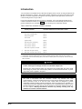
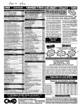
MicroTech®
Modem Kit
Telephone
Line
Modem
Controller
cns no. a0006
© 1996 McQuay International
Contents
Contents................................................................................................................................................. 2
Figures ................................................................................................................................................... 2
Tables .................................................................................................................................................... 2
Introduction ........................................................................................................................................... 3
General Information .............................................................................................................. 4
Component Data.................................................................................................................................... 4
Modem............................................................................................................................................... 4
Modem Interface Cable ..................................................................................................................... 5
Extension Cable................................................................................................................................. 6
Installation.............................................................................................................................. 7
Mounting the Modem ............................................................................................................................ 7
Wiring the Interface Cable .................................................................................................................... 7
Connecting the Cables and Connectors ................................................................................................. 8
Interface Cable/Extension Cable ....................................................................................................... 8
AMP Connector................................................................................................................................. 8
34-Pin Call Initiate Connector ........................................................................................................... 9
Power Plug ........................................................................................................................................ 9
Phone Jack......................................................................................................................................... 9
Modem Configuration ......................................................................................................................... 10
Port/Connect Speed ......................................................................................................................... 10
Changing Controller Port Speed ...................................................................................................... 10
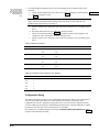
Configuration String ........................................................................................................................ 11
Service Information ............................................................................................................. 13
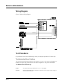
Wiring Diagram................................................................................................................................... 13
Test Procedures ................................................................................................................................... 13
Troubleshooting Power Problems.................................................................................................... 13
Troubleshooting Communications Problems................................................................................... 14
Figures
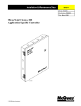
Figure 1. Modem System Block Diagram ............................................................................................. 4
Figure 2. Aprotek Model 7600 Modem (14.4 kbps).............................................................................. 5
Figure 3. Interface Cable ....................................................................................................................... 6
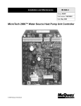
Figure 4. Modem Dimensions ............................................................................................................... 7
Figure 5. MicroTech Controller (200 Series) ........................................................................................ 9
Figure 6. Modem Wiring Diagram ...................................................................................................... 13
Tables
Table 1. MicroTech Controller Installation Literature .......................................................................... 3
Table 2. Power Supply Terminals (12 to 17 Vdc) ................................................................................. 8
Table 3. Memory Locations................................................................................................................. 11
Table 4. Controller Communications Port Speeds............................................................................... 11
Table 5. AT Command Definitions ..................................................................................................... 12
McQuay, AAF, and MicroTech are registered trademarks of McQuay International.
MicroTech 2000, Monitor, and Open Protocol are trademarks of McQuay International.
All other trademarks are the property of their respective owners.
2
IM 682
Introduction
You can monitor various MicroTech controllers and panels from a remote site using the MicroTech
Modem and Monitor™ software. This manual contains installation procedures for the MicroTech®
Modem. It contains component descriptions, field wiring options and requirements, and network
commissioning and service procedures.
For specific information about unit or auxiliary controllers, refer to the appropriate MicroTech
controller installation manual (see Table 1). For installation and commissioning instructions and
general information on a particular unit, refer to its model-specific installation manual.
Table 1. MicroTech Controller Installation Literature
MicroTech unit or
auxiliary controller
Installation & Maintenance Data bulletin number
Series-100 centrifugal chiller
IM 403
Series-200 centrifugal chiller
IM 616
Reciprocating chiller
IM 493
Screw chiller
IM 549
Applied rooftop
IM 483
Self-contained air conditioning
IM 608
Series-100 unit ventilator
IM 509
Series-300 unit ventilator
IM 613
MicroTech Loop Water Controller
IM 431
{
MicroTech Absorption Gateway
IM 620
|
MicroTech Communications Gateway
IM 661
Notes:
1. The MicroTech Absorption Gateway (MAG) is an interface to McQuay absorption chillers, which use Sanyo controllers.
2. The MicroTech Communications Gateway (MCG) is an interface to McQuay water source heat pumps, which use MicroTech
2000™ controllers.
!
CAUTION
Static sensitive components.
A static discharge can damage electronic circuit board components.
Discharge any static electrical charge by touching the bare metal inside the control panel
before doing any service work. Never unplug cables, circuit board terminal blocks, or power
plugs while power is applied to the panel.
NOTICE
This equipment generates, uses and can radiate radio frequency energy and, if not installed
and used in accordance with this instruction manual, may interfere with radio
communications. It has been tested and found to comply with the limits for a Class A digital
device, pursuant to part 15 of the FCC rules. These limits are designed to provide
reasonable protection against harmful interference when the equipment is operated in a
commercial environment. Operation of this equipment in a residential area is likely to cause
harmful interference in which case the user is required to correct the interference at his or
her own expense. McQuay International disclaims any liability resulting from any
interference or for the correction thereof.
IM 682
3
General Information
This manual contains information on the components, installation, and service of the MicroTech®
Modem Kit. You can monitor various MicroTech panels and controllers from a remote or off-site
location with the MicroTech Modem and MicroTech Monitor™. See the list below for the
MicroTech controllers that can incorporate a modem.
•
Network Master Panel (NMP)
•
Series 200 Application Specific Controller (ASC-200)
•
Loop Water Controller (LWC)
•
Application Specific Controller (ASC)
•
Remote Monitoring and Sequencing Panel (RMS)
•
Remote Monitoring and Control Panel (RMC)
•
Chiller System Controller (CSC)
•
Chiller Plant Controller (CPC)
•
Centrifugal Chiller Unit Controller
•
Reciprocating Chiller Unit Controller
•
Self-contained Air Conditioning Unit Controller
•
Screw Chiller Unit Controller
•
Applied Rooftop Unit Controller
Component Data
The MicroTech Modem Kit includes a modem, an interface cable, an extension cable, mounting
brackets, and a ¼–inch foam gasket.
Modem
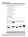
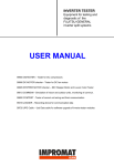
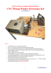
A modem is the communications interface between a MicroTech controller and a telephone line. It
can connect a remote PC using another modem to the controller so that the PC operator at the remote
site can monitor the controller. Figure 1 shows how modems can connect a MicroTech Controller to a
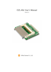
remote PC. The MicroTech modem is an Aprotek Model 7600, 14,400 bps data/fax modem.
Figure 1. Modem System Block Diagram
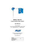
The modem has a DB-9 (female) RS-232 port, an RJ-11C phone jack, and a 2-pin header for power.
Note: To monitor MicroTech controllers via a modem, your PC must have a modem and the
appropriate MicroTech Monitor software.
4
IM 682
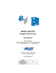
Phone Jack
The phone jack (RJ-11C) accepts a standard telephone line plug. The phone jack is opposite the
RS-232 port. A connector on the telephone line mates to the phone jack. By calling the telephone
number assigned to the modem and having the appropriate PC software and modem, you can
communicate with the MicroTech controller.
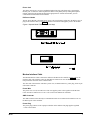
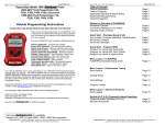
DC Power Header
The DC Power Header is the input for DC power. The 2-pin header is adjacent to the RS-232 port. A
plug on the interface cable (see Figure 2) connects to the header and supplies power to the modem.
Figure 2. Aprotek Model 7600 Modem (14.4 kbps)
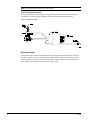
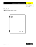
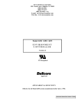
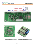
Modem Interface Cable
The Modem Interface Cable connects the modem to the MicroTech controller. Figure 3 shows the
interface cable. The cable has a nine-pin male RS-232 connector on one end that is secured to the
nine-pin female connector on the extension cable.
The other end of the interface cable has a power wire, an AMP connector, a power plug, and a 34-pin
call initiate connector.
Power Wire
The power wire is a red, 22 AWG wire. This wire supplies power to the regulator in the Interface
Cable. It must be connected to a 12 to 17 Vdc source in the MicroTech controller.
AMP Connector
The AMP connector mates directly to Communication Port A on a MicroTech controller. Port A is
the RS-232 port of the controller.
Power Plug
The power plug connects to the 2-pin power header on the modem. This plug supplies regulated
+5 Vdc to the modem.
IM 682
5
Note: The controller must supply power to the modem.
34-Pin Call Initiate Connector
The 34-pin call initiate connector attaches to the Analog Inputs socket in a MicroTech controller.
This feature is used only when the modem is connected to a Modem Alarm Unit (MAU).
Figure 3. Interface Cable
Extension Cable
The Extension Cable connects the Modem Interface Cable to the modem. The cable has a nine-pin
male RS-232 connector on one end and a nine-pin female RS-232 connector on the other end. The
female connector is secured to the nine-pin male connector on the interface cable with screws. The
male connector mates with the female connector on the modem.
6
IM 682
Installation
Installing the modem kit consists in mounting the modem to the panel, wiring the interface cable to
the controller, and connecting cables and a telephone line to the modem.
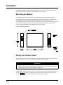
Mounting the Modem
To mount the modem in a control panel, use the mounting bracket provided with the modem kit.
A U-shaped bracket fits around the modem and holds it in place in the panel. A ¼-inch thick foam
gasket is placed between the bracket and the modem. Locate an area in the panel that can
accommodate the bracket and modem. Refer to the product-specific installation manuals for details on
where the modem should be mounted. Place the modem and foam gasket inside and the bracket.
Secure the modem and bracket to the panel using the screws provided.
Figure 4. Modem Dimensions
Wiring the Interface Cable
Wiring the interface cable involves finding the power source for the power wire. The red power wire
must be connected to a 12 to 17 Vdc power supply inside the MicroTech panel.
!
CAUTION
Voltage surge or short can cause damage to the controller.
Turned off power to the controller before you connect the power wire in order to prevent
shorting the power supply or having a sudden voltage surge.
On NMP, RMS, or RMC controllers, pin 8 on the Aux/Out connector strip provides approximately 13
Vdc (see Figure 5). A factory wired pigtail on the Aux/Out connector with a crimp-style socket is
provided. The power lead is then inserted into the pigtail socket and crimped.
IM 682
7
If the MicroTech panel has a field wiring terminal that is connected to a 12 to 17 Vdc power supply,
connect the power wire to that terminal. Refer to Table 2 for power supply field wiring terminals in
the various MicroTech controllers that supply 12 to 17 Vdc.
Table 2. Power Supply Terminals (12 to 17 Vdc)
MicroTech Controller
Terminal
Applied rooftop
TB6-42
Screw chiller
TB4-41
Reciprocating chiller
TB7-146
Centrifugal chiller
Terminal 67
Application Specific Controller (ASC)
TB3-25 or TB3-26
Self-contained Air Conditioning (SCAC)
12 Vdc terminal
Loop Water Controller (LWC)
TS2-13
Chiller Plant Controller (CPC)
TS2-13
Series 200 Application Specific Controller (ASC-200)
13 Vdc terminal
Chiller System Controller (CSC)
13 Vdc terminal
Note: Measure the voltage at the field wiring terminal before connecting the power wire to ensure
that the voltage is correct.
Connecting the Cables and Connectors
There are several connections to make before the interface cable wiring is complete.
Interface Cable/Extension Cable
The interface cable has a 9-pin male connector that mates to the female connector on the extension
cable. Mate and secure the two connectors together by tightening the screws on the extension cable
connector.
Note: Be careful when you tighten the screws on the connector. Do not turn one screw more than two
rotations before you turn the other screw. This prevents damage to the pins and the connectors.
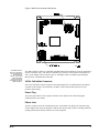
AMP Connector
The AMP connector attaches to Communication Port A of a MicroTech controller (see Figure 5).
Insert the AMP connector into Port A.
8
IM 682
Figure 5. MicroTech Controller (200 Series)
The AMP connector
must be connected to
the controller before
the modem can
operate. The modem
signal and power
ground connections
are made through the
AMP connector..
The AMP connector connects to all modem-compatible MicroTech controllers except the Application
Specific Controller (ASC). The ASC has a Phoenix-type connector. If the modem is connected to an
ASC, use the adapter cable to connect to Port A. The adapter cable is available by purchasing the
MicroTech PC Communications Cable Kit.
34-Pin Call Initiate Connector
The 34-pin call initiate connector plugs into the Analog Inputs port of a Modem Alarm Unit (MAU)
controller. If the modem is not connected to an MAU, coil the unused cable and secure it to the
interface cable housing.
Power Plug
The power plug connects to the 2-pin power header on the modem. This connection supplies
regulated power to the modem.
Phone Jack
The RJ-11C phone jack is the communications port of the modem. The phone jack accepts the plug
on the telephone line. Insert the telephone connector into the jack until you hear a clicking sound. The
clicking sound ensures that the connectors are secured together.
IM 682
9
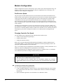
Modem Configuration
Modem configuration consists in setting the port speed, connect speed, and configuration string. The
modem is ready to use when it arrives on site because the configuration is set at the factory. You
should not need to change the configuration.
Port/Connect Speed
The port speed is the data transmission rate between the MicroTech controller and the MicroTech
modem, and the connect speed is the data transmission rate between two modems. Modems negotiate
connect speed with each other to find the highest speed where both modems can conduct reliable
communications. The port speed of the MicroTech modem is set to 9600 bps at the factory. The
Port A speed of the controller must match the port speed of the modem before communications can
begin. To change the Port A speed of the controller, you must change the value of a memory location
of the controller.
The MicroTech modem adjusts its port speed to match the port speed of a processor sending it any
AT command. For example, if you were to connect your PC to the modem and set the RS-232 (serial)
port of the PC to 2400 bps and then send the modem an AT command, any AT command, the modem
would adjust its port speed to 2400 bps and continue to use 2400 bps until you changed the port
speed.
Changing Controller Port Speed
You can change the port configuration of the controller in three different ways.
•
Change it on the controller keypad display
•
Change a Monitor table
•
Change the controller memory
When you use a Remote Monitoring and Sequencing Panel (RMS) or a Remote Monitoring and
Control Panel (RMC), you can change the port configuration with the keypad display. Refer to the
appropriate Operation Manual for more information.
Also, you can change the port configuration in some Monitor programs. Consult your Monitor User’s
Manual or contact your McQuayService representative for more details.
If you cannot change the port configuration with the keypad or in a Monitor table, see you Monitor
User’s Manual for procedures to change controller memory locations.
!
CAUTION
Never change the Port B speed.
Will cause loss of communications with the network.
Do not change the Port B speed under any circumstance because the controller
communicates with the rest of the network via Port B at a fixed transmission rate of 9600
bps.
To change the Controller Port Configuration
Use a PC with the appropriate Monitor software.
1. Connect an IBM compatible PC directly to Port A of the controller using the PC cable from the
PC Communications Cable Kit. The PC Communications Cable Kit is available from McQuay
International.
2. Open your Monitor application. See the Monitor User’s Manual for details.
10
IM 682
If you cannot make a
direct connection to
the controller, contact
your McQuayService
representative for
help.
1.
Use the Read/Write command to directly access and change the non-volatile memory of the
controller.
a. Change the data transmission rate of Port A. See Table 3 for memory locations and see
b. Table 4 for parameter values.
Note: Transmission rates for both ports are stored in one byte of memory (two hexadecimal
digits). The most significant hexadecimal digit represents the rate of Port B and the least
significant digit represents the rate of Port A.
c.
d.
e.
f.
Initiate a software reset: change the value of the Reset location to an even number greater
that 2.
Record the EOS Checksum. See Table 3 for memory locations.
The Correct Checksum must match the EOS Checksum in order for the program to run.
Change the Correct Checksum to the EOS Checksum value.
Initiate a software reset: change the value of the Reset location to an even number greater
that 2.
Table 3. Memory Locations
Parameter
Controller Series
Memory Location (Hex)
Port Transmission Rate
100
8010
200
0A10
EOS Calculated Checksum
Correct Checksum
Software Reset
100
8002
200
0A02
100
8001
200
0A01
100
0204
200
0204
Table 4. Controller Communications Port Speeds.
Baud Rate
Hex Code
300
4
1200
6
2400
8
4800
9
9600
B
Configuration String
The modem configuration string is an AT command that initializes the modem. This configuration is
set at the factory and resides in the non-volatile memory of the modem. If a problem with
configuration occurs, the configuration string must be reset. You can reset the configuration string
from PC running a general purpose communications program such as Terminal in Windows. Connect
the modem to the serial port of the PC and issue the AT command.
The following AT command configures the modem: AT&F0S0=1B0E0Q1&D0&K0&W0. Table 5
explains each command in the string.
IM 682
11
Table 5. AT Command Definitions
Commands
Description
AT Commands
&F0
Restore Factory Settings
AT&F0
S0=n
Enables Auto Answer (>0)
ATS0=1
Bn
CCITT Standard (0)
ATB0
En
Disable Char Echo (0)
ATE0
Qn
No Result Codes
ATQ1
&Dn
Ignore DTR (0)
AT&D0
&Kn
Disable Flow Control
At&K0
&Wn
Write Settings to NVRAM Template 0
AT&W0
Note: For high speed modems, flow control must be disabled.
12
IM 682
Service Information
Wiring Diagram
Figure 6. Modem Wiring Diagram
Test Procedures
If a problem still exists after troubleshooting, contact your McQuay representative for further help.
Troubleshooting Power Problems
The red power lead in the modem interface cable connects to a 12 to 17 Vdc source in the MicroTech
controller. The power plug on the interface cable delivers regulated +5 Vdc power to the modem.
The Modem Does Not Power Up.
IM 682
Cause:
The power lead is not connected to a 12 to 17 Vdc supply.
Solution:
Refer to the product-specific installation manuals to find a proper voltage supply in
the MicroTech controller.
13
Cause:
The power lead is improperly connected to the controller voltage supply.
Solution:
Check the connection to the power supply.
Cause:
The power plug is not connected to the modem.
Solution:
Connect the power plug to the 2-pin power header on the modem.
Cause:
The interface cable may have a poor solder/connection point at the power plug.
Solution:
Measure the resistance (ohms) with a VOM (Volt-Ohmeter) or DMM (Digital
Multimeter) to verify the correct wiring.
Cause:
The AMP connector is not plugged into Port A of the MicroTech controller.
Solution:
Plug the AMP connector into Port A of the Micro-Tech controller.
Cause:
The AMP connector has a poor connection.
Solution:
Measure the resistance (ohms) using a VOM (Volt-Ohmeter) or DMM (Digital
Multimeter) to verify the correct wiring. Use the wiring diagram in Figure 6.
Cause:
The interface cable is not properly connected to the modem extension cable.
Solution:
Reconnect the interface cable to the extension cable.
Cause:
The interface cable may have a broken or pushed in male connector pin.
Solution:
Disconnect the interface cable and inspect for broken or pushed in pins.
Troubleshooting Communications Problems
If you cannot establish a communications link or it is lost, you may have a communications problem.
The Computer Cannot Communicate with the MicroTech Controller via the Modem.
14
Cause:
The phone line is not connected to the phone jack on the modem.
Solution:
Connect the phone line to the modem’s phone jack.
Cause:
The AMP connector is not properly connected to Port A of the controller.
Solution:
Reconnect the AMP connector to Port A of the controller.
Cause:
The AMP connector has a poor connection.
Solution:
Measure the resistance (ohms) using a DVM (Digital Voltmeter) to verify the
correct wiring. Use the wiring diagram in Figure 6.
Cause:
The connect/port speed does not match the port speed of the MicroTech controller.
Solution:
Connect the modem to a PC and change the modem configuration. See Modem
Configuration on page 10 for details.
IM 682
Cause:
The configuration string of the modem is incorrect.
Solution:
Re-enter the configuration string using a PC and the correct communications
software (see Table 5).
Cause:
The communications password is incorrect.
Solution:
Enter the correct password in the Monitor program and try again or contact
McQuay Service.
If a problem still exists after troubleshooting, contact McQuayService.
IM 682
15
13600 Industrial Park Blvd., P.O. Box 1551, Minneapolis, MN 55440
(612) 553-5330