1
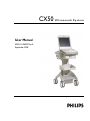
CX50
Ultrasound System
User Manual
4535 613 06532 Rev A
September 2008
© 2008 Koninklijke Philips Electronics N.V. All rights reserved. Published in USA.
Manufactured by Philips Ultrasound
22100 Bothell-Everett Highway
Bothell, WA 98021-8431
USA
Telephone: +1 425-487-7000 or 800-426-2670
Fax: +1 425-485-6080
www.philips.com/ultrasound
This Medical Device meets the provisions of the transposition of the Medical
Device Directive 93/42/EEC within the country of origin of the Notified Body
concerned with the device.
European Union Representative
Philips Medical Systems Nederland B.V., a Philips Healthcare Company
PMS Quality and Regulatory Affairs Europe
Veenpluis 4-6
5684 PC Best
The Netherlands
CAUTION
United States federal law restricts this device to sale by or on the order of a
physician.
This document and the information contained in it is proprietary and confidential information of Philips Medical Systems
("Philips") and may not be reproduced, copied in whole or in part, adapted, modified, disclosed to others, or disseminated
without the prior written permission of the Philips Legal Department. This document is intended to be used by customers
and is licensed to them as part of their Philips equipment purchase. Use of this document by unauthorized persons is
strictly prohibited.
Philips provides this document without warranty of any kind, implied or expressed, including, but not limited to, the
implied warranties of merchantability and fitness for a particular purpose.
Philips has taken care to ensure the accuracy of this document. However, Philips assumes no liability for errors or
omissions and reserves the right to make changes without further notice to any products herein to improve reliability,
function, or design. Philips may make improvements or changes in the products or programs described in this document
at any time.
This product may contain remanufactured parts equivalent to new in performance, or parts that have had incidental use.
Philips Ultrasound products may be manufactured under or operate in accordance with one or more of the following
United States patents and corresponding patents in other countries: U.S. Patent Numbers 6,450,958; 6,527,721; 6,679,849;
6,572,547; 6,471,649; 6,540,685. Other patent applications are pending in various countries.
"Chroma," "Color Kinesis," "QLAB," and "XRES" are trademarks of Koninklijke Philips Electronics N.V.
Non-Philips product names may be trademarks of their respective owners.
2
CX50 User Manual
4535 613 06532
Contents
1
2
Read This First..........................................................................................13
Intended Audience............................................................................................................13
Warnings..............................................................................................................................13
Warning Symbols...............................................................................................................14
User Information Components......................................................................................14
Product Conventions........................................................................................................15
User Information Conventions.......................................................................................16
Upgrades and Updates.....................................................................................................17
Customer Comments.......................................................................................................18
Supplies and Accessories.................................................................................................18
Customer Service..............................................................................................................19
WEEE Recycling Information..........................................................................................20
Safety.........................................................................................................21
Electrical Safety..................................................................................................................21
Defibrillators.................................................................................................................25
Mechanical Safety...............................................................................................................26
Equipment Protection.......................................................................................................27
Symbols................................................................................................................................28
Biological Safety..................................................................................................................34
FDA Medical Alert on Latex......................................................................................36
ALARA Education Program.......................................................................................38
Output Display.............................................................................................................43
Control Effects..............................................................................................................46
Related Guidance Documents..................................................................................49
Acoustic Output and Measurement........................................................................50
Acoustic Output Tables..............................................................................................53
Acoustic Measurement Precision and Uncertainty..............................................53
Operator Safety.................................................................................................................55
CX50 User Manual
4535 613 06532
3
Contents
3
4
Repetitive Strain Injury .................................................................................................55
Philips Transducers..........................................................................................................55
Glutaraldehyde Exposure...............................................................................................56
Infection Control.............................................................................................................56
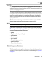
Electromagnetic Compatibility ..........................................................................................58
Radio-Frequency Emissions...........................................................................................59
ECG Signal.........................................................................................................................60
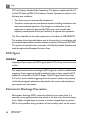
Electrostatic Discharge Precautions............................................................................60
Electromagnetic Emissions............................................................................................61
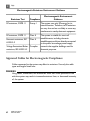
Approved Cables for Electromagnetic Compliance.................................................62
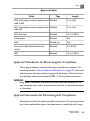
Approved Transducers for Electromagnetic Compliance.......................................63
Approved Accessories for Electromagnetic Compliance.......................................63
Electromagnetic Immunity.............................................................................................64
Electromagnetic Interference........................................................................................69
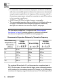
Recommended Separation Distance...........................................................................71
Avoiding Electromagnetic Interference.......................................................................73
Use Restrictions Due to Interference........................................................................74
System Overview........................................................................................75
System Capabilities...............................................................................................................75
Measurements..................................................................................................................75
Transducer Types.............................................................................................................76
Image Acquisition and Review......................................................................................76
Patient Data Protection.................................................................................................76
System Options.....................................................................................................................76
Imaging Options...............................................................................................................77
Connectivity Options.....................................................................................................77
Clinical/Analysis Options...............................................................................................77
Calculations.......................................................................................................................77
QLAB Advanced Quantification Software Options.................................................78
Stress Echocardiography................................................................................................78
CX50 User Manual
4535 613 06532
Contents
4
Data Security....................................................................................................................79
System Components............................................................................................................79
Video Monitor..................................................................................................................80
Control Panel...................................................................................................................81
On/Off (Power) Switch..................................................................................................81
Data Storage ....................................................................................................................82
Peripherals.........................................................................................................................82
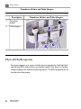
Transducer Receptacles and Cable Management.....................................................83
Physio (ECG) Receptacles.............................................................................................84
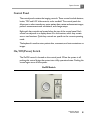
USB Hub............................................................................................................................85
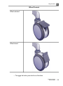
Wheel Controls...............................................................................................................86
Preparing the System.................................................................................89
Connecting Devices..............................................................................................................89
External Printers..............................................................................................................90
Connecting an External Printer....................................................................................91
Configuring Local Printers.............................................................................................91
Connecting the Optional Foot Switch........................................................................92
Connecting an External Color Monitor ....................................................................92
Connecting the System to a Network.............................................................................93
Attaching the System............................................................................................................94
System Configuration...........................................................................................................94
Standard Network Support...........................................................................................94
DICOM Networking Option........................................................................................95
Configuration Information.............................................................................................95
Entering System Network Settings..............................................................................96
Changing the PC Name..................................................................................................99
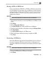
Wireless Networking.....................................................................................................99
Enabling a Wireless Network Connection..............................................................100
Configuring Wireless Network Properties.............................................................102
Removing a Wireless Network..................................................................................103
CX50 User Manual
4535 613 06532
5
Contents
5
6
Troubleshooting Wireless Network Connections................................................104
Remote Access..............................................................................................................104
Configuring the System to Enable Remote Access...............................................105
Repairing Network Connections...............................................................................105
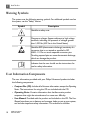
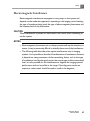
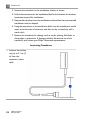
Moving the System..............................................................................................................106
Preparing and Moving...................................................................................................107
Setting Up After Moving..............................................................................................108
Environmental Requirements...........................................................................................108
Using the System......................................................................................111
Turning the System On and Off.......................................................................................111
Setting the System Time and Date..................................................................................112
System Cart..........................................................................................................................113
Attaching the System....................................................................................................113
Adjusting Cart Height..................................................................................................113
Using the Wheel Controls..........................................................................................114
Monitor Settings..................................................................................................................116
Changing the Monitor Tint.........................................................................................116
Changing the Monitor Brightness..............................................................................116
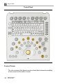
System Controls..................................................................................................................117
Control Panel.................................................................................................................117
Control Status................................................................................................................118
Changing Control Panel Brightness...........................................................................119
Automatic Brightness Control ..................................................................................120
Enabling Automatic Brightness Control ..................................................................120
Quick Key Controls......................................................................................................120
Using Quick Key Controls..........................................................................................121
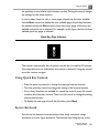
System Keyboard...........................................................................................................121
Typing Special Characters............................................................................................122
Typing Accented Characters.......................................................................................122
Status Icons.....................................................................................................................123
CX50 User Manual
4535 613 06532
Contents
6
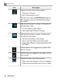
Power Management............................................................................................................125
Battery and AC Indicators..........................................................................................125
Changing Power Management Settings.....................................................................126
AC Adapter Operation ....................................................................................................127
AC Adapter Indicator...................................................................................................128
Using the AC Adapter..................................................................................................128
Battery Operation..............................................................................................................129
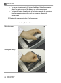
Installing the Battery ...................................................................................................131
System Security...................................................................................................................133
Logging On to the System...........................................................................................133
Logging Off of the System...........................................................................................133
Temporary ID.................................................................................................................134
Starting Emergency Studies.........................................................................................134
System and Data Security............................................................................................135
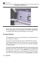
Imaging Display....................................................................................................................136
Image Size Settings..............................................................................................................138
Transducer Use....................................................................................................................138
Connecting Transducers..............................................................................................138
Selecting a Transducer..................................................................................................140
Selecting a Preset..........................................................................................................140
Using Presets..................................................................................................................140
Physio Feature......................................................................................................................141
DVD and USB Devices......................................................................................................141
Media Compatibility......................................................................................................142
Loading and Ejecting a Disc.........................................................................................143
USB Devices...................................................................................................................143
Erasing a DVD or USB Device...................................................................................145
Formatting a USB Device............................................................................................145
Customizing the System..........................................................................147
Presets...................................................................................................................................147
CX50 User Manual
4535 613 06532
7
Contents
7
8
Clinical Options and Predefined Presets..................................................................147
Custom Presets.............................................................................................................148
Creating Custom Presets............................................................................................148
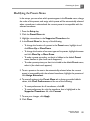
Modifying Custom Presets..........................................................................................149
Deleting Custom Presets............................................................................................149
Presets Menu..................................................................................................................150
Using the Presets Menu...............................................................................................150
Modifying the Presets Menu........................................................................................151
Copying Custom Presets.............................................................................................152
System Setups......................................................................................................................152
Changing Setups.............................................................................................................153
Options.................................................................................................................................153
Installing Temporary Options.....................................................................................154
Performing a Study...................................................................................155
New Patient Studies...........................................................................................................155
Entering Patient Data Manually (Without Worklist).............................................156
Using Modality Worklist..............................................................................................157
Selecting a Transducer.......................................................................................................157
Imaging Modes.....................................................................................................................158
Using 2D Mode..............................................................................................................158
Annotation............................................................................................................................159
Placing a System-Defined Label on the Display......................................................159
Typing a Label on the Display.....................................................................................160
Placing a Body Marker on the Display......................................................................160
Printing..................................................................................................................................161
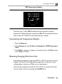
Review...................................................................................................................................161
Starting Review..............................................................................................................162
Navigating Thumbnails and Images............................................................................162
Acquiring Images and Loops ...........................................................................................163
Measurement and Analysis................................................................................................163
CX50 User Manual
4535 613 06532
Contents
8
9
Performing a 2D Distance Measurement.................................................................165
Obtaining a Typical Labeled Measurement..............................................................165
Obtaining a Calculation Result...................................................................................166
Ending a Study......................................................................................................................166
Transducers................................................................................................169
Selecting a Transducer.......................................................................................................169
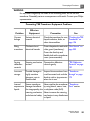
Clinical Options and Transducers...................................................................................170
Transducer Care..................................................................................................................170
Acoustic Artifacts...............................................................................................................170
Transducer Covers.............................................................................................................174
Transducer Storage.............................................................................................................174
Storage for Transport .................................................................................................175
Daily and Long-Term Storage.....................................................................................175
Transesophageal Transducers..................................................................177
Operators of TEE Transducers........................................................................................177
Patient Safety During TEE Studies...................................................................................177
Patient-Contact Parts...................................................................................................182
Preventing TEE Transducer Problems............................................................................182
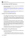
Electrical Safety and TEE Transducers............................................................................184
Leakage Current and TEE Transducers....................................................................184
Reducing Risks of Using TEE Transducers...............................................................184
TEE Deflection Control Basics .......................................................................................185
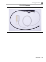
Connecting a TEE Transducer..........................................................................................186
X7-2t TEE Transducer Description................................................................................186
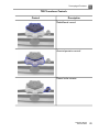
TEE Transducer Components..........................................................................................188
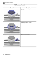
TEE Deflection Controls.............................................................................................190
Manipulating the TEE Tip.............................................................................................192
Rotating the TEE Image Plane ...................................................................................195
Checking the TEE Transducer....................................................................................196
Special Considerations for TEE Studies.........................................................................197
CX50 User Manual
4535 613 06532
9
Contents
Preparing Patients for TEE Studies............................................................................197
TEE Study Guidelines...................................................................................................198
Tip Fold-Over......................................................................................................................199
TEE Temperature Sensing.................................................................................................199
Ensuring Safe TEE Temperatures...............................................................................200
Manual Auto-Cool Feature.........................................................................................201
Patient Temperature.....................................................................................................201
Entering Patient Temperature.....................................................................................202
Temperature Display.....................................................................................................202
Customizing the Temperature Display.....................................................................203
Resuming Imaging After Auto-Cool..........................................................................203
Patient Care After a TEE Study.......................................................................................204
TEE Accessories and Supplies..........................................................................................205
Bite Guards.....................................................................................................................205
TEE Transducer Covers...............................................................................................205
Tip Protectors................................................................................................................206
Disposable Drapes........................................................................................................206
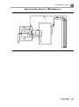
TEE Leakage Current Test................................................................................................206
TEE Test Background....................................................................................................206
Testing TEE Transducer Leakage Current................................................................209
TEE Transducer References..............................................................................................210
10 Transducer Care.......................................................................................211
Disinfectants and Gels Safety...........................................................................................211
Latex Product Alert......................................................................................................213
Transmissible Spongiform Encephalopathy..............................................................213
Acoustic Coupling Medium..............................................................................................214
Choosing a Disinfectant.....................................................................................................214
General Cleaning for All Transducers............................................................................215
Cleaning a Transducer..................................................................................................215
Disinfecting Transducers using a Wipe or Spray Method .........................................216
10
CX50 User Manual
4535 613 06532
Contents
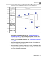
Cleaning and Disinfecting Cables and Connectors.....................................................218
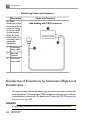
Disinfection of Transducers by Immersion (High-Level Disinfection)....................220
Disinfecting Transducers by Immersion...................................................................221
Disinfecting TEE Transducers by Immersion................................................................223
Disinfecting TEE Transducers in an Automated Disinfector.....................................225
Sterilizing Transducers.......................................................................................................227
Disinfectants Compatibility...............................................................................................229
Disinfectant Types.........................................................................................................230
Factors Affecting Disinfectant Efficiency..................................................................230
Disinfectants Compatibility Table..............................................................................231
Gels Compatibility..............................................................................................................235
11 System Maintenance................................................................................237
Cleaning and Maintaining the System.............................................................................237
Cleaning the System and ECG Equipment..............................................................237
Disinfectants for System Surfaces..............................................................................239
Disinfecting System Surfaces.......................................................................................239
Cleaning the Trackball..................................................................................................241
Cleaning the Battery.....................................................................................................241
Cleaning the Adapter...................................................................................................242
Transducer Maintenance....................................................................................................242
Printer Maintenance...........................................................................................................242
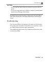
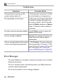
Troubleshooting...................................................................................................................243
Error Messages....................................................................................................................244
For Assistance......................................................................................................................245
CX50 User Manual
4535 613 06532
11
Contents
12
CX50 User Manual
4535 613 06532
1 Read This First
This section contains important information about the user information for
your system and about contacting Philips Ultrasound.
Intended Audience
Before you use your user information, you need to be familiar with ultrasound
techniques. Sonography training and clinical procedures are not included here.
Before you use your QLAB user information, you need to be familiar with
diagnostic techniques. Sonography training and clinical procedures are not
included here.
This manual is intended for sonographers, physicians, and biomedical engineers
who operate and maintain your Philips Ultrasound product.
Warnings
Before using the system, read these warnings and the "Safety" section.
WARNINGS
• Do not remove system covers; hazardous voltages are present inside the
system. To avoid electrical shock, use only supplied power cords and
connect only to properly grounded wall (wall/mains) outlets.
• Do not operate the system in the presence of flammable anesthetics.
Explosion can result.
• Medical equipment needs to be installed and put into service according to
the special electromagnetic compatibility (EMC) guidelines provided in the
"Safety" section.
• The use of portable and mobile radio-frequency (RF) communications
equipment can affect the operation of medical equipment.
CX50 User Manual
4535 613 06532
13
1
Read This First
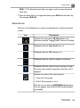
Warning Symbols
The system uses the following warning symbols. For additional symbols used on
the system, see the "Safety" section.
Symbol
Description
Identifies a safety note.
Dangerous voltages: Appears adjacent to high-voltage
terminals, indicating the presence of voltages greater
than 1,000 Vac (600 Vac in the United States).
Identifies ESD (electrostatic-discharge) sensitivity of a
connector that is not tested as specified in IEC
60601-1-2. Do not touch exposed connector pins.
Touching exposed pins can cause electrostatic discharge,
which can damage the product.
Indicates that the user should see the instructions for
use for safety information.
User Information Components
The user information provided with your Philips Ultrasound product includes
the following components:
• Compact Disc (CD): Includes all of the user information, except the Operating
Notes. The instructions for using the CD are included with the CD.
• Operating Notes: Contains information that clarifies certain product
responses that might be misunderstood or cause user difficulty.
• User Manual: Provided with the product and included on the CD. The User
Manual introduces you to features and concepts, helps you set up your system,
and includes important safety information. This manual also includes
14
CX50 User Manual
4535 613 06532
Read This First
•
•
•
•
•
1
procedures for basic operation. For detailed operating instructions, see the
Help.
Help: Available on the system in some languages and included on the CD,
the Help contains comprehensive instructions for using the system. The Help
also provides reference information and descriptions of all controls and display
elements. To display the Help, press Help on the system keyboard.
QLAB Help: Available on the product in some languages, the QLAB Help
contains comprehensive instructions for use. It also provides descriptions of
all controls and display elements. To display the Help, press Help on the
system keyboard, or click ?.
Acoustic Output Tables: Included on the CD, it contains information about
acoustic output and patient-applied part temperatures.
Medical Ultrasound Safety: Included on the CD, it contains information on
bioeffects and biophysics, prudent use, and implementing ALARA (as low as
reasonably achievable).
Shared Roles for System and Data Security: Contains guidelines to help
you understand how the security of your ultrasound system could be
compromised and information on Philips efforts to help you prevent security
breaches.
Product Conventions
Your Philips product uses certain conventions throughout the interface to make
it easy for you to learn and use:
• Two unlabeled buttons are used with the trackball. Those controls, located
on either side of the trackball, operate somewhat similarly to PC mouse
buttons.
• Tabs along the top of the monitor display let you choose additional sets of
setup options.
• To type text into a text field, click in the field and use the keyboard.
•
To display a list, click the down arrow
. To scroll through a list, click the
arrows at either end of the scroll bar or drag the scroll box up or down.
CX50 User Manual
4535 613 06532
15
1
Read This First
• Controls on the control panel include buttons, knobs, slide controls, and a
trackball. Press a button to activate or deactivate its function. Turn a knob
to change the selected setting. Move a slide control to change its setting. Roll
the trackball in the direction that you want to move a caliper or object.
• Controls across the top of the control panel, called quick keys, function as
both buttons and knobs. To select one of the functions displayed above the
control, simply press the control. To select a setting for the function, also
displayed above the control, turn the control.
User Information Conventions
The user information for your Philips product uses the following typographical
conventions to assist you in finding and understanding information:
• Hypertext links appear in blue.
• All procedures are numbered, and all subprocedures are lettered. You must
complete steps in the sequence they are presented to ensure success.
• Bulleted lists indicate general information about a particular function or
procedure. They do not imply a sequential procedure.
• Control names and menu items or titles are spelled as they are on the system,
and they appear in bold text. The only exceptions are the trackball and the
buttons adjacent to it, which are unlabeled.
• Symbols appear as they appear on the system.
• Point means to position the tip of the pointer or cursor on an item on the
display.
• Click means to move the pointer to an object and press the left trackball
button.
• Select means to click a check box to put a check mark in it. Deselect means
clicking the check box to remove the check mark.
• Double-click means to quickly click twice to select an object or text.
• Right-click means to point at an item and then press and immediately release
the right trackball button.
• Hover means to pause the pointer over an item on the display.
16
CX50 User Manual
4535 613 06532
Read This First
1
• Drag means to place the pointer over an object and then press and hold the
left trackball button while moving the trackball. Use this method to move an
object on the display.
• Highlight means to change the color of a display selection (such as an item in
a list) or overlay it with a colored bar, usually by clicking.
• The left side of the system is to your left as you stand in front of the system,
facing the system. The front of the system is nearest to you as you operate
it.
• Transducers and pencil probes both are referred to as transducers, unless
the distinction is important to the meaning of the text.
QLAB Help topics may contain information that is different for the PC and
ultrasound editions of the QLAB software. Where this occurs, the information
common to both editions is presented first, followed by the PC-specific
information, and then the ultrasound-specific information.
Information that is essential for the safe and effective use of your Philips product
appears throughout your user information as follows:
WARNING
Warnings highlight information vital to the safety of you, the operator, and the
patient.
CAUTION
Cautions highlight ways that you could damage the product and consequently
void your warranty or service contract.
NOTE
Notes bring your attention to important information that will help you operate
the product more effectively.
Upgrades and Updates
Philips Ultrasound is committed to innovation and continued improvement.
Upgrades may be announced that consist of hardware or software improvements.
Updated user information will accompany those upgrades.
CX50 User Manual
4535 613 06532
17
1
Read This First
Customer Comments
If you have questions about the user information, or you discover an error in
the user information, in the USA, please call Philips Ultrasound Customer Service
at 800-722-9377; outside the USA, please call your local customer service
representative. You can also send e-mail to Philips Ultrasound Technical
Communications at the following address:
[email protected]
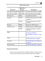
Supplies and Accessories
To order additional system batteries for your CX50 system, contact your Philips
representative.
To order ECG trunk cables, lead sets, and electrodes; transducer covers; biopsy
guides; and other supplies and accessories, contact CIVCO Medical Solutions:
CIVCO Medical Solutions
102 First Street South, Kalona, IA 52247-9589
Telephone: 800-445-6741 (USA and Canada), +1 319-656-4447 (International)
Fax: 877-329-2482 (USA and Canada), +1 319-656-4451 (International)
E-mail: [email protected]
Internet: www.civco.com
NOTE
Model or part numbers in the following tables are subject to change.
18
CX50 User Manual
4535 613 06532
Read This First
1
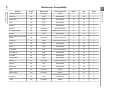
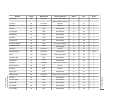
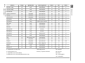
System Accessories
Accessory
Model/Part
Number
Description
ECG cable lead set (AAMI) 453561365771
ECG three-lead cable lead set (AAMI)
ECG cable lead set (IEC)
453561365781
ECG three-lead cable lead set (IEC)
ECG electrode
40420A
Pre-gelled snap electrode
Tip guards
610-748
Transducer tip protector for most TEE
transducers
667-094
Transducer tip protector for X7-2t
transducers
Bite guard
M2203A
Bite guard for TEE transducers
Transducer covers
610-680
Protective sheath for TEE transducers
610-833
Covers for noninvasive or noncavity
transducers
Cables
See "Approved Cables for
Electromagnetic Compliance" on page
62
Printers
–
Transducers
–
See "Clinical Options and Transducers"
on page 170
Removable media
–
See "Media Compatibility" on page 142
See "External Printers" on page 90
Customer Service
Customer service representatives are available worldwide to answer questions
and to provide maintenance and service. Please contact your local Philips
CX50 User Manual
4535 613 06532
19
1
Read This First
Ultrasound representative for assistance. You can also contact one of the
following offices for referral to a customer service representative, or visit the
Philips Ultrasound Web site:
www.philips.com/ultrasound
Corporate and North American Headquarters
22100 Bothell-Everett Highway, Bothell, WA 98021-8431, USA
800-722-9377
Asia Pacific Headquarters
Level 9, Three Pacific Place, 1 Queen's Road East, Wanchai, Hong Kong
+852 2821 5888
European Headquarters (also serves Africa and the Middle East)
Philips Medizin Systeme Böblingen GmbH
Hewlett-Packard-Str. 2, 71034 Böblingen, Germany
+49 40 5078 4532
Latin American Headquarters
1550 Sawgrass Corporate Parkway, Suite 300, Sunrise, FL 33323, USA
+1 954-628-1000
WEEE Recycling Information
The European Union Directive on Waste Electrical and Electronic Equipment
(WEEE) requires producers of electrical and electronic equipment to provide
reuse and treatment information for each product. This information identifies,
for reuse centers and treatment and recycling facilities, the electrical and
electronic components and materials and the location of dangerous substances
and preparations in the equipment. Such "recycling passports" for Philips
Ultrasound systems are available on this Web site:
www.medical.philips.com/main/company/sustainability/recycling/ultrasound/
20
CX50 User Manual
4535 613 06532
2 Safety
Please read this information before using your ultrasound system. It applies to
the ultrasound system, transducers, recording devices, and any optional
equipment. This section covers general safety information only. Safety
information that applies only to a specific task is included in the procedure for
that task.
This device is intended for use by, or by the order of, and under the supervision
of a licensed physician qualified to direct the use of the device.
A WARNING describes precautions necessary to prevent injury or loss of
life.
A CAUTION describes precautions necessary to protect the equipment.
Electrical Safety
This equipment has been verified by a recognized third-party testing agency
as a Class I device with Type BF and Type CF isolated patient-applied parts,
and Type B non-isolated patient-applied parts. (The safety standards met by
this system are included in the "Specifications" section of the Help.) For
maximum safety observe these warnings and cautions:
CX50 User Manual
4535 613 06532
21
2
Safety
WARNINGS
• Shock hazards may exist if this system (when mounted on its cart or plugged
directly into an AC power source), including all externally mounted recording
and monitoring devices, is not properly grounded. Protection against electrical
shock is provided by grounding the cart or the AC power adapter with a
three-wire cable and plug, which must be plugged into a grounded outlet. The
grounding wire must not be removed or defeated.
• To avoid the risk of electrical shock, never connect the system power cord
to a power strip or extension cord. When using the power cord, always
connect it directly to a grounded wall outlet.
• Use only the AC adapter supplied with your system.
• Because Type B transducers are not isolated and have a higher inherent
leakage current, those transducers are not intended for invasive use.
• Do not remove the protective covers on the system; hazardous voltages are
present inside. Cabinet panels must be in place while the system is in use. All
internal adjustments and replacements must be made by a qualified Philips
Ultrasound field service engineer.
• Do not operate this system in the presence of flammable gases or anesthetics.
Explosion can result. The system is not compliant in AP/APG environments
as defined by IEC 60601-1.
• To avoid risk of electrical shock hazards, always inspect the transducer before
use: Check the face, housing, and cable before use. Do not use if the face is
cracked, chipped, or torn; the housing is damaged; or the cable is abraded.
• To avoid risk of electrical shock hazards, always turn off the system, disconnect
it from the wall outlet, and remove the battery (see "Installing the Battery"
on page 131) before cleaning the system.
• All patient-contact devices, such as transducers, pencil probes, and ECG leads
not specifically indicated as defibrillation-proof must be removed from patient
contact before application of a high-voltage defibrillation pulse. See
"Defibrillators" on page 25.
• During transesophageal echocardiographic (TEE) procedures, either remove
the TEE transducer from the patient or disconnect the TEE transducer from
the system immediately following image acquisition.
22
CX50 User Manual
4535 613 06532
Safety
2
• Ultrasound equipment in normal operation, as with other medical electronic
diagnostic equipment, uses high-frequency electrical signals that can interfere
with pacemaker operation. Though the possibility of interference is slight, be
alert to this potential hazard and stop system operation immediately if you
note interference with a pacemaker.
• When using additional peripheral equipment powered from an electrical
source other than the ultrasound system, the combination is considered to
be a medical system. It is your responsibility to comply with IEC 60601-1-1
and test the system to those requirements. If you have questions, contact
your Philips representative.
• Do not use nonmedical peripherals, such as report printers, within 1.5 m
(5 ft) of a patient, unless the nonmedical peripherals receive power from an
isolated power outlet on the Philips ultrasound system, or from an isolation
transformer that meets medical safety standards, as defined by standard
IEC 60601-1-1.
• The system and patient-applied parts meet the standard IEC 60601-1. Applied
voltages exceeding the standard, although unlikely, may result in electrical
shock to the patient or operator.
• Connection of optional devices not supplied by Philips Ultrasound could result
in electrical shock. When such optional devices are connected to your
ultrasound system, ensure that the total system earth leakage current does
not exceed 500 µA, or in the United States, 300 µA.
• To avoid risk of electrical shock, do not use any transducer that has been
immersed beyond the specified cleaning or disinfection level. See the
"Transducer Care" section.
• To avoid risks of electrical shock and fire hazards, inspect the system power
cord and plug regularly. Ensure that they are not damaged in any way.
• Do not drape the power cord over any of the cable hooks or the handle on
the system cart. Damage to the cord or power receptacle unit can occur if
the cart is raised.
• Operating the system with physio input signals that are below the specified
minimum levels may cause inaccurate results. See the "Specifications" section
in the Help.
CX50 User Manual
4535 613 06532
23
2
Safety
• Electrosurgical units (ESUs) and other devices intentionally introduce radio
frequency electromagnetic fields or currents into patients. Because imaging
ultrasound frequencies are coincidentally in the radio frequency range,
ultrasound transducer circuits are susceptible to radio frequency interference.
While an ESU is in use, severe noise interferes with the black-and-white image
and completely obliterates the color image. Concurrent failures in an ESU or
other device and in the outer layer of the TEE transducer shaft can cause
electrosurgical currents to return along the transducer conductors. This could
burn the patient, and the ultrasound system and the transducer could also be
damaged. Be aware that a disposable transducer cover provides no protective
electrical insulation at ESU frequencies.
• To avoid risk of a burn hazard, do not use transducers with high-frequency
surgical equipment. A burn hazard may result from a defect in the
high-frequency surgical neutral electrode connection.
• Using cables, transducers, and accessories other than those specified for use
with the system may result in increased emissions from, or decreased immunity
of, the system.
24
CX50 User Manual
4535 613 06532
Safety
2
CAUTIONS
• Although your system has been manufactured in compliance with existing
EMI/EMC requirements, use of this system in the presence of an
electromagnetic field can cause momentary degradation of the ultrasound
image. When interference is present or intermittent, use caution when
continuing to use the system. If interference occurs often, review the
environment in which the system is being used, to identify possible sources
of radiated emissions. These emissions could be from other electrical devices
used within the same room or an adjacent room. Communication devices
such as cellular phones and pagers can cause these emissions. The existence
of radio, TV, or microwave transmission equipment located nearby can cause
emissions. In cases where EMI is causing disturbances, it may be necessary to
relocate your system.
• For information on electromagnetic emissions and immunity as it applies to
the system, see "Electromagnetic Compatibility" on page 58. Ensure that the
operating environment of your system meets the conditions specified in the
referenced information. Operating the system in an environment that does
not meet those conditions may degrade system performance.
Defibrillators
Observe the following warnings when using a transducer when a defibrillation
is required.
WARNINGS
• Before defibrillation, always remove the transducer from the patient.
• Before defibrillation, always disconnect the transducer from the system.
• A disposable transducer cover provides no protective electrical insulation
against defibrillation.
• A small hole in the outer layer of the transducer opens a conductive path to
grounded metal parts of the transducer. The secondary arcing that could
occur during defibrillation could cause patient burns. The risk of burns is
reduced, but not eliminated, by using an ungrounded defibrillator.
CX50 User Manual
4535 613 06532
25
2
Safety
Use defibrillators that do not have grounded patient circuits. To determine
whether or not a defibrillator patient circuit is grounded, see the defibrillator
service guide, or consult a biomedical engineer.
Mechanical Safety
A list of precautions related to mechanical safety follows; observe these
precautions when using the system:
WARNINGS
• Be aware of the wheels on the system cart, especially when moving the system.
The system could cause injury to you or others if it rolls over feet or into
shins. Use caution when going up or down ramps.
• When attempting to overcome an obstacle, do not push the system from
either side with excessive force, which could cause the system to tip over.
• Position external hardcopy devices away from the system. Ensure that they
are secure. Do not stack them on the system.
• When positioning the monitor, move it carefully to avoid pinching hands or
extremities against other objects, such as a bed rail.
• Never park the system on an incline.
• The brakes are intended as a convenience. To increase cart security, use
wheel chocks when the system is parked.
• If system operation is abnormal after you move or transport the system,
contact Philips Ultrasound Customer Service immediately. System components
are installed securely and can withstand considerable shock, but excessive
shock can cause a system failure.
• To avoid injury, Philips recommends against lifting the system cart.
26
CX50 User Manual
4535 613 06532
Safety
2
CAUTIONS
• Before moving the system, ensure that the system is secured for transport.
On some systems, that may include ensuring that the monitor is latched, to
prevent monitor damage during transport.
• Ensure that the cables for all patient-applied parts are secure before moving
the system. Use the cable management system to ensure that transducer
cables are protected from damage.
• Do not roll the system over transducer cables or power cables.
Equipment Protection
Follow these precautions to protect your system:
CX50 User Manual
4535 613 06532
27
2
Safety
CAUTIONS
• Excessive bending or twisting of cables on patient-applied parts may cause
failure or intermittent operation of the system. Do not roll the system over
cables, which may damage them.
• Improper cleaning or sterilization of a patient-applied part may cause
permanent damage. For cleaning and disinfection instructions, see the
"Transducer Care" section.
• Do not submerge the cables of patient-applied parts in solution. The cables
are not liquid-tight beyond the applied part/cable or cable/connector interfaces.
• In general, only the area of the transducer acoustic window is liquid-tight.
Except where specified in specific transducer-cleaning instructions, do not
immerse the remainder of a transducer in any liquid.
• Do not use solvents, such as thinner or benzine, or abrasive cleaners on the
system, transducers, or any hardcopy device.
• For optimal performance, connect your ultrasound system to a circuit
dedicated solely for the system. Do not connect life-support devices to the
same circuit as the ultrasound system.
• If systems, transducers, and peripherals have been in an environment of 10°C
(50°F) or below, allow them to reach room temperature before connecting
or turning them on. Philips recommends allowing 24 hours for complete
normalization. Otherwise, condensation inside the devices could cause damage.
• To avoid damaging the flat-panel display in the monitor, do not store the
system where the ambient temperature exceeds 65°C (149°F).
Symbols
The International Electrotechnical Commission (IEC) has established a set of
symbols for medical electronic equipment that classify a connection or warn of
potential hazards. Of those symbols, the following may be used on your
ultrasound system and its accessories and packaging.
28
CX50 User Manual
4535 613 06532
Safety
2
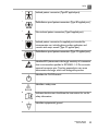
Isolated patient connection (Type BF applied part).
Defibrillation-proof patient connection (Type BF applied part).
Non-isolated patient connection (Type B applied part).
Isolated patient connection for applied part intended for
intraoperative use, including direct cardiac application and
contact with major vessels (Type CF applied part).
Defibrillation-proof patient connection (Type CF applied part).
Identifies ESD (electrostatic-discharge) sensitivity of a connector
that is not tested as specified in IEC 60601-1-2. Do not touch
exposed connector pins. Touching exposed pins can cause
electrostatic discharge, which can damage the product.
Identifies the On/Off control.
Identifies a safety note.
Indicates that the user should see the instructions for use for
safety information.
Identifies equipotential ground.
CX50 User Manual
4535 613 06532
29
2
Safety
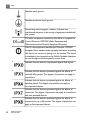
Identifies earth ground.
Identifies protective earth ground.
Nonionizing electromagnetic radiation. Indicates that
interference may occur in the vicinity of equipment marked with
this symbol.
The radio component contained in this device is compliant to
Council Directive 1999/5/EC (Radio Equipment and
Telecommunications Terminal Equipment Directive).
Class 2 radio equipment identifier per Directive 1999/5/EC.
European Union member states may apply restrictions on putting
this device into service or placing it on the market. This device
is intended to be connected to the Publicly Available Interfaces
for use throughout the European Economic Area.
Indicates that the device is unprotected against fluid ingress.
Indicates that the device is protected against the effects of
vertically falling water. This degree of protection can apply to
transducers.
Indicates that the device is protected against the effects of
splashing liquids. This degree of protection can apply to
foot-operated devices.
Indicates that the device is protected against the effects of
immersion. This degree of protection can apply to transducers
and foot-operated devices.
Indicates that the device is protected against the effects of
immersion for up to 60 minutes. This degree of protection can
apply to foot-operated devices.
30
CX50 User Manual
4535 613 06532
Safety
2
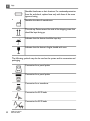
Indicates the need for separate collection for electrical and
electronic equipment in compliance with the Waste Electrical
and Electronic Equipment (WEEE) Directive. When accompanied
by
or
, components of the device may contain lead or
mercury, respectively, which must be recycled or disposed of
in accordance with local, state, or federal laws. The backlight
lamps in an LCD system monitor contain mercury.
Do not throw away. Dispose of in accordance with local, state,
or federal laws.
Global Medical Device Nomenclature Code.
Indicates a possible crushing hazard to hands.
Warns that the system should not be used stacked with other
equipment. If the system is used stacked with or adjacent to
other equipment, verify normal operation before use.
Indicates the temperature range (noncondensing) for transport
and storage. (Does not apply to media.)
Indicates the atmospheric pressure range for transport and
storage.
Indicates the relative humidity range (noncondensing) for
transport and storage
Indicates that a connector receives alternating current.
CX50 User Manual
4535 613 06532
31
2
Safety
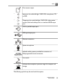
Identifies fuse boxes or their locations. For continued protection
from fire and shock, replace fuses only with fuses of the same
type and rating.
Identifies the date of manufacture.
This side up: Points toward the side of the shipping crate that
should be kept facing up.
Indicates that the device should be kept dry.
Indicates that the device is fragile; handle with care.
The following symbols may also be used on the system and its accessories and
packaging:
Connection for a pencil probe
Connection for a pencil probe
Connection for a transducer
Connection for ECG leads
Connection for ECG leads
32
CX50 User Manual
4535 613 06532
Safety
2
Print remote output
Input port for audio left/right, VHS/S-VHS, microphone, CD,
or DVD
Output port for audio left/right, VHS/S-VHS, video patient
monitor, black-and-white printer, or interlaced RGB output
port
VGA or parallel output port
USB input/output port
Ethernet connection
System microphone
Isolated auxiliary power provided for connection of
Philips-approved remote accessories
Foot switch
Indicates the atmospheric pressure range for transport and
storage.
The following symbols may be used inside the system:
CX50 User Manual
4535 613 06532
33
2
Safety
Dangerous voltages: Appears adjacent to
high-voltage terminals, indicating the presence of
voltages greater than 1,000 Vac (600 Vac in the
United States).
Indicates equipotential ground.
Biological Safety
This section contains information about biological safety and a discussion of the
prudent use of the system.
A list of precautions related to biological safety follows; observe these precautions
when using the system. For more information refer to Medical Ultrasound Safety
on your user information CD.
34
CX50 User Manual
4535 613 06532
Safety
2
WARNINGS
• Do not use the system if an error message on the video display indicates that
a hazardous condition exists. Note the error code, turn off power to the
system, and call your customer service representative.
• Do not use a system that exhibits erratic or inconsistent image updating.
Discontinuities in the scanning sequence indicate a hardware failure that must
be corrected before use.
• Perform ultrasound procedures prudently. Use the ALARA (as low as
reasonably achievable) principle.
• Use only acoustic standoffs that have been approved by Philips Ultrasound.
For information on ordering approved accessories, see "Supplies and
Accessories" on page 18.
• Transducer covers may contain natural rubber latex. Those covers may cause
allergic reactions in some individuals. See "FDA Medical Alert on Latex" on
page 36.
• The M2203A bite guard strap contains natural rubber latex, which may cause
allergic reactions. See "FDA Medical Alert on Latex" on page 36.
• In contrast studies using a high-MI acoustic field, capillary rupture, due to
microbubble expansion within a capillary in an acoustic field, can cause
extravasation. References: (1) Skyba, D.M., Price, R.J., Linka, A.Z., Skalak, T.C.,
Kaul, S. "Direct in vivo visualization of intravascular destruction of
microbubbles by ultrasound and its local effects on tissue." Circulation, 1998;
98:290-293. (2) van Der Wouw, P.A., Brauns, A.C., Bailey, S.E., Powers, J.E.,
Wilde, A.A. "Premature ventricular contractions during triggered imaging
with ultrasound contrast." Journal of the American Society of Echocardiography,
2000;13(4):288-94.
• Preventricular contractions can be caused by the oscillations of microbubbles
when a high-MI acoustic field is triggered in the heart at the end of systole.
In a very sick patient with certain risk factors, theoretically, this could lead
to ventricular fibrillation. Reference: van Der Wouw, P.A., Brauns, A.C., Bailey,
S.E., Powers, J.E., Wilde, A.A. "Premature ventricular contractions during
triggered imaging with ultrasound contrast." Journal of the American Society of
Echocardiography, 2000;13(4):288-94.
CX50 User Manual
4535 613 06532
35
2
Safety
• If a sterile transducer cover becomes compromised during an intraoperative
application involving a patient with transmissible spongiform encephalopathy,
such as Creutzfeldt-Jakob disease, follow the guidelines of the U.S. Centers
for Disease Control and this document from the World Heath Organization:
WHO/CDS/ APH/2000/3, WHO Infection Control Guidelines for
Transmissible Spongiform Encephalopathies. The transducers for your system
cannot be decontaminated using a heat process.
• If the system becomes contaminated internally with bodily fluids carrying
pathogens, you must immediately notify your Philips service representative.
Components inside the system cannot be disinfected. In that case, the system
must be disposed of as biohazardous material in accordance with local or
federal laws.
• The backlight lamps in the system displays contain mercury and must be
recycled or disposed of according to local, state, or federal laws.
• Select the correct application when starting an exam, and remain in that
application throughout the exam. Some applications are for parts of the body
that require lower limits for acoustic output.
• The CX50 system is not qualified for ophthalmic use.
• When used off the cart, the AC adapter and the system should not be placed
on the floor or on a patient's bed. You can place it on a table or chair.
FDA Medical Alert on Latex
March 29, 1991, Allergic Reactions to Latex-Containing Medical Devices
Because of reports of severe allergic reactions to medical devices containing
latex (natural rubber), the FDA is advising health care professionals to identify
their latex sensitive patients and be prepared to treat allergic reactions promptly.
Patient reactions to latex have ranged from contact urticaria to systemic
anaphylaxis. Latex is a component of many medical devices, including surgical
and examination gloves, catheters, intubation tubes, anesthesia masks, and dental
dams.
Reports to the FDA of allergic reactions to latex-containing medical devices have
increased lately. One brand of latex cuffed enema tips was recently recalled after
36
CX50 User Manual
4535 613 06532
Safety
2
several patients died as a result of anaphylactoid reactions during barium enema
procedures. More reports of latex sensitivity have also been found in the medical
literature. Repeated exposure to latex both in medical devices and in other
consumer products may be part of the reason that the prevalence of latex
sensitivity appears to be increasing. For example, it has been reported that 6%
to 7% of surgical personnel and 18% to 40% of spina bifida patients are latex
sensitive.
Proteins in the latex itself appear to be the primary source of the allergic
reactions. Although it is not now known how much protein is likely to cause
severe reactions, the FDA is working with manufacturers of latex-containing
medical devices to make protein levels in their products as low as possible.
FDA’s recommendations to health professionals in regard to this problem are
as follows:
• When taking general histories of patients, include questions about latex
sensitivity. For surgical and radiology patients, spina bifida patients and health
care workers, this recommendation is especially important. Questions about
itching, rash or wheezing after wearing latex gloves or inflating a toy balloon
may be useful. Patients with positive histories should have their charts flagged.
• If latex sensitivity is suspected, consider using devices made with alternative
materials, such as plastic. For example, a health professional could wear a
non-latex glove over the latex glove if the patient is sensitive. If both the
health professional and the patient are sensitive, a latex middle glove could
be used. (Latex gloves labeled “Hypoallergenic” may not always prevent
adverse reactions.)
• Whenever latex-containing medical devices are used, especially when the
latex comes in contact with mucous membranes, be alert to the possibility
of an allergic reaction.
• If an allergic reaction does occur and latex is suspected, advise the patient of
a possible latex sensitivity and consider an immunologic evaluation.
• Advise the patient to tell health professionals and emergency personnel about
any known latex sensitivity before undergoing medical procedures. Consider
advising patients with severe latex sensitivity to wear a medical identification
bracelet.
CX50 User Manual
4535 613 06532
37
2
Safety
The FDA is asking health professionals to report incidents of adverse reactions
to latex or other materials used in medical devices. (See the October 1990 FDA
Drug Bulletin.) To report an incident, call the FDA Problem Reporting Program,
operated through the U.S. Pharmacopoeia toll-free number: 800-638-6725. (In
Maryland, call collect 301-881-0256.)
For a single copy of a reference list on latex sensitivity, write to: LATEX, FDA,
HFZ-220, Rockville, MD 20857.
NOTE
The ultrasound system and transducers described in this document do not
contain natural rubber latex that contacts humans. Natural rubber latex is not
used on any Philips ultrasound transducer. It also is not used on Philips ECG
cables for the products described in this document.
ALARA Education Program
The guiding principle for the use of diagnostic ultrasound is defined by the "as
low as reasonably achievable" (ALARA) principle. The decision as to what is
reasonable has been left to the judgment and insight of qualified personnel. No
set of rules can be formulated that would be sufficiently complete to dictate the
correct response to every circumstance. By keeping ultrasound exposure as low
as possible, while obtaining diagnostic images, users can minimize ultrasonic
bioeffects.
Since the threshold for diagnostic ultrasound bioeffects is undetermined, it is
the sonographer’s responsibility to control total energy transmitted into the
patient. The sonographer must reconcile exposure time with diagnostic image
quality. To ensure diagnostic image quality and limit exposure time, an ultrasound
system provides controls that can be manipulated during the exam to optimize
the results of the exam.
The ability of the user to abide by the ALARA principle is important. Advances
in diagnostic ultrasound, not only in the technology but in the applications of
that technology, have resulted in the need for more and better information to
guide the user. The output display indices are designed to provide that important
information.
38
CX50 User Manual
4535 613 06532
Safety
2
There are a number of variables which affect the way in which the output display
indices can be used to implement the ALARA principle. These variables include
index values, body size, location of the bone relative to the focal point, attenuation
in the body, and ultrasound exposure time. Exposure time is an especially useful
variable, because it is controlled by the user. The ability to limit the index values
over time supports the ALARA principle.
Applying ALARA
The system imaging mode used depends upon the information needed. 2D and
M-mode imaging provide anatomical information, while Doppler, Color Power
Angio (CPA), and Color imaging provide information about blood flow. A scanned
mode, like 2D or Color, disperses or scatters the ultrasonic energy over an area,
while an unscanned mode, like M-mode or Doppler, concentrates ultrasonic
energy. Understanding the nature of the imaging mode being used allows the
sonographer to apply the ALARA principle with informed judgment. Additionally,
the transducer frequency, system setup values, scanning techniques, and operator
experience allow the sonographer to meet the definition of the ALARA principle.
The decision as to the amount of acoustic output is, in the final analysis, up to
the system operator. This decision must be based on the following factors: type
of patient, type of exam, patient history, ease or difficulty of obtaining
diagnostically useful information, and the potential localized heating of the patient
due to transducer surface temperatures. Prudent use of the system occurs when
patient exposure is limited to the lowest index reading for the shortest amount
of time necessary to achieve acceptable diagnostic results.
Although a high index reading does not mean that a bioeffect is actually occurring,
a high index reading should be taken seriously. Every effort should be made to
reduce the possible effects of a high index reading. Limiting exposure time is an
effective way to accomplish this goal.
There are several system controls that the operator can use to adjust the image
quality and limit the acoustic intensity. These controls are related to the
techniques that an operator might use to implement ALARA. These controls
can be divided into three categories: direct, indirect, and receiver controls.
CX50 User Manual
4535 613 06532
39
2
Safety
Acoustic Output Limits
This ultrasound system maintains acoustic output below the appropriate limits
for each application, as listed here.
Limits for Non-Ophthalmic Applications
• Ispta (derated) ≤ 720 mW/cm2
• MI ≤ 1.9
• TI ≤ 6.0
WARNING
The CX50 system is not qualified for ophthalmic use.
Direct Controls
Application selection and the output-power control directly affect acoustic
intensity. There are different ranges of allowable intensity or output based on
your selection. Selecting the correct range of acoustic intensity for the application
is one of the first things that occurs in any exam. For example, peripheral vascular
intensity levels are not recommended for fetal exams. Some systems automatically
select the proper range for a particular application, while others require manual
selection. Ultimately, the user has the responsibility for proper clinical use. The
ultrasound system provides both automatic (default) settings and manual
(user-selectable) settings.
Output power has direct impact on acoustic intensity. Once the application has
been established, the power control can be used to increase or decrease the
intensity output. The power control allows you to select intensity levels less
than the established maximum. Prudent use dictates that you select the lowest
output intensity that is consistent with good image quality.
Indirect Controls
The indirect controls are those that have an indirect effect on acoustic intensity.
These controls affect imaging mode, pulse repetition frequency, focus depth,
pulse length, and transducer selection.
40
CX50 User Manual
4535 613 06532
Safety
2
The choice of imaging mode determines the nature of the ultrasound beam. 2D
is a scanning mode; Doppler is a stationary or unscanned mode. A stationary
ultrasound beam concentrates energy in a single location. A moving or scanned
ultrasound beam disperses the energy over an area and the beam is concentrated
on the same area for a fraction of the time as that of an unscanned mode.
Pulse repetition frequency or rate refers to the number of ultrasound bursts of
energy over a specific period of time. The higher the pulse repetition frequency,
the more pulses of energy in a period of time. Several controls affect pulse
repetition frequency: focal depth, display depth, sample volume depth, flow
optimization, scale, number of focal zones, and sector-width controls.
Focus of the ultrasound beam affects the image resolution. To maintain or
increase resolution at a different focus requires a variation in output over the
focal zone. This variation of output is a function of system optimization. Different
exams require different focal depths. Setting the focus at the proper depth
improves the resolution of the structure of interest.
Pulse length is the time during which the ultrasonic burst is turned on. The longer
the pulse, the greater the time-average intensity value. The greater the
time-average intensity, the greater the likelihood of temperature increase and
cavitation. Pulse length, burst length, or pulse duration is the output pulse
duration in PW Doppler. Increasing the Doppler sample-volume size increases
the pulse length.
Transducer selection indirectly affects intensity. Tissue attenuation changes with
frequency. The higher the transducer operating frequency, the greater the
attenuation of the ultrasonic energy. A higher transducer operating frequency
requires more output intensity to scan at a deeper depth. To scan deeper at the
same output intensity, a lower transducer frequency is required. Using more
gain and output beyond a point, without corresponding increases in image quality,
can mean that a lower frequency transducer is needed.
Receiver Controls
Receiver controls are used by the operator to improve image quality. These
controls have no effect on output. Receiver controls only affect how the
ultrasound echo is received. These controls include gain, TGC, dynamic range,
CX50 User Manual
4535 613 06532
41
2
Safety
and image processing. The important thing to remember, relative to output, is
that receiver controls should be optimized before output is increased. For
example, before increasing output, optimize gain to improve image quality.
An Example of Applying the ALARA Principle
An ultrasound scan of a patient’s liver begins with selecting the appropriate
transducer frequency. After selecting the transducer and the application, which
are based on patient anatomy, adjustments to output power should be made to
ensure that the lowest possible setting is used to acquire an image. After the
image is acquired, adjusting the focus of the transducer, and then increasing the
receiver gain to produce a uniform representation of the tissue follows. If an
adequate image can be obtained with the increase in gain, then a decrease in
output should be made. Only after making these adjustments should you increase
output to the next level.
Having acquired the 2D display of the liver, Color can be used to localize blood
flow. As with the 2D image display, gain and image processing controls must be
optimized before increasing output.
Having localized the blood flow, use the Doppler controls to position the sample
volume over the vessel. Before increasing output, adjust velocity range or scale
and Doppler gain to obtain an optimal Doppler trace. Only if maximum Doppler
gain does not create an acceptable image do you increase output.
In summary: Select the correct transducer frequency and application for the job;
start with a low output level; and optimize the image by using focus, receiver
gain, and other imaging controls. If the image is not diagnostically useful at this
point, then increase output.
Additional Considerations
Ensure that scanning time is kept to a minimum, and ensure that only medically
required scanning is performed. Never compromise quality by rushing through
an exam. A poor exam may require a follow-up, which ultimately increases
exposure time. Diagnostic ultrasound is an important tool in medicine, and like
any tool, it should be used efficiently and effectively.
42
CX50 User Manual
4535 613 06532
Safety
2
Output Display
The system output display comprises two basic indices: a mechanical index and
a thermal index. The thermal index further consists of the following indices: soft
tissue (TIS), bone (TIB), and cranial bone (TIC). One of these three thermal
indices will be displayed at all times. Which one depends upon the system preset
or user choice, depending upon the application at hand.
The mechanical index is continuously displayed over the range of 0.0 to 1.9, in
increments of 0.1 for all applications except contrast, where the minimum
increment is 0.01.
The thermal index comprises three indices, and only one of these is displayed
at any one time. Each transducer application has a default selection that is
appropriate for that combination. The TIB, TIS, or TIC is continuously displayed
over the range of 0.0 to maximum output, based on the transducer and
application, in increments of 0.1. For the location of the output display, see
"Imaging Display" on page 136.
The application-specific nature of the default setting is also an important factor
of index behavior. A default setting is a system control state that is preset by
the manufacturer or the operator. The system has default index settings for the
transducer application. The default settings are invoked automatically by the
ultrasound system when power is turned on, when new patient data is entered
into the system data base, or when an application change occurs.
The decision as to which of the three thermal indices to display should be based
on the following criteria:
• Appropriate index for the application: TIS is used for imaging soft tissue, TIB
for a focus at or near bone, and TIC for imaging through bone near the surface,
as in a cranial exam.
• Mitigating factors that might create artificially high or low thermal index
readings: location of fluid or bone, or blood flow. For example, is there a
highly attenuating tissue path so that the actual potential for local zone heating
is less than the thermal index displays?
CX50 User Manual
4535 613 06532
43
2
Safety
• Scanned modes versus unscanned modes of operation affect the thermal
index. For scanned modes, heating tends to be near the surface; for unscanned
modes, the potential for heating tends to be deeper in the focal zone.
• Always limit ultrasound exposure time. Do not rush the exam. Ensure that
the indices are kept to a minimum and that exposure time is limited without
compromising diagnostic sensitivity.
Mechanical Index (MI) Display
Mechanical bioeffects are threshold phenomena that occur when a certain level
of output is exceeded. The threshold level varies, however, with the type of
tissue. The potential for mechanical bioeffects varies with peak rarefactional
pressure and ultrasound frequency. The MI accounts for these two factors. The
higher the MI value, the greater the likelihood of mechanical bioeffects occurring.
There is no specific MI value that means that a mechanical effect is actually
occurring. The MI should be used as a guide for implementing the ALARA
principle.
Thermal Index (TI) Displays
The TI informs the user about the conditions that exist that might lead to an
increase in temperature at the surface of the body, within the body tissue, or at
the point of focus of the ultrasound beam on bone. That is, the TI informs the
user of the potential for temperature rise in body tissue. It is an estimate of
temperature increase in body tissue with specific properties. The actual amount
of any temperature rise is influenced by factors such as tissue type, vascularity,
mode of operation, and others. The TI should be used as a guide for implementing
the ALARA principle.
The bone thermal index (TIB) informs the user about potential heating at or
near the focus after the ultrasound beam has passed through soft tissue or fluid;
for example, at or near second- or third-trimester fetal bone.
The cranial bone thermal index (TIC) informs the user about the potential heating
of bone at or near the surface; for example, cranial bone.
The soft tissue thermal index (TIS) informs the user about the potential for
heating within soft homogeneous tissue.
44
CX50 User Manual
4535 613 06532
Safety
2
You can choose to display TIS, TIC, or TIB. (For details on changing the TI display,
see the system Help.) On systems with transcranial applications, TIC is displayed
when you select a transcranial preset.
Mechanical and Thermal Indices Display Precision and Accuracy
The MI and TI precision is 0.1 unit on the system.
The MI and TI display accuracy estimates for the system are given in Acoustic
Output Tables, on your user information CD. Those accuracy estimates are based
on the variability range of transducers and systems, inherent acoustic output
modeling errors, and measurement variability, as discussed in this section.
The displayed values should be interpreted as relative information to help the
system operator achieve the ALARA principle through prudent use of the system.
The values should not be interpreted as actual physical values in interrogated
tissue or organs. The initial data that is used to support the output display is
derived from laboratory measurements based on the American Institute of
Ultrasound in Medicine (AIUM) measurement standard. The measurements are
then put into algorithms for calculating the displayed output values.
Many of the assumptions used in the process of measurement and calculation
are conservative in nature. Overestimation of actual in situ intensity exposure,
for the vast majority of tissue paths, is built into the measurement and calculation
process. For example:
• The measured water tank values are derated using a conservative, industry
standard, attenuation coefficient of 0.3 dB/cm-MHz.
• Conservative values for tissue characteristics were selected for use in the TI
models. Conservative values for tissue or bone absorption rates, blood
perfusion rates, blood heat capacity, and tissue thermal conductivity were
selected.
• Steady State temperature rise is assumed in the industry standard TI models,
and the assumption is made that the ultrasound transducer is held steady in
one position long enough for steady state to be reached.
A number of factors are considered when estimating the accuracy of the displayed
values: hardware variations, estimation algorithm accuracy, and measurement
CX50 User Manual
4535 613 06532
45
2
Safety
variability. Variability among transducers and systems is a significant factor.
Transducer variability results from piezoelectric crystal efficiencies,
process-related impedance differences, and sensitive lens-focusing parameter
variations. Differences in system pulser voltage control and efficiencies is also a
contributor to variability. There are inherent uncertainties in the algorithms used
to estimate acoustic output values over the range of possible system operating
conditions and pulser voltages. Inaccuracies in laboratory measurements are
related to, among others, differences in hydrophone calibration and performance,
positioning, alignment, and digitization tolerances, and variability among test
operators.
The conservative assumptions of the output estimation algorithms of linear
propagation, at all depths, through a 0.3 dB/cm-MHz attenuative medium is not
considered in the accuracy estimate for the display. Neither linear propagation,
nor uniform attenuation at the 0.3 dB/cm-MHz rate, occur in water tank
measurements or in most tissue paths in the body. In the body, different tissues
and organs have dissimilar attenuation characteristics. In water, there is almost
no attenuation. In the body, and in particular, in water tank measurements,
nonlinear propagation and saturation losses occur as pulser voltages increase.
Therefore, the display accuracy estimates are based on the variability range of
transducers and systems, inherent acoustic output modeling errors, and
measurement variability. Display accuracy estimates are not based on errors in,
or caused by measuring according to, the AIUM measurement standards, or the
effects of nonlinear loss on the measured values.
Control Effects
Controls Affecting the Indices
As various system controls are adjusted, the TI and MI values may change. This
will be most apparent as the output power control is adjusted; but other system
controls affect the on-screen output values.
46
CX50 User Manual
4535 613 06532
Safety
2
Power
The output power control affects the system acoustic output. Two real-time
output values are on the display: a TI and MI. They change as the system responds
to power-control adjustments.
In combined modes, such as simultaneous Color, 2D, and PW Doppler, the
individual modes each add to the total TI. One mode will be the dominant
contributor to this total. The displayed MI will be from the mode with the largest
MI.
2D Controls
• Sector Width: Narrowing the sector angle may increase frame rate. This
action will increase the TI. Pulser voltage may be automatically adjusted down
with software controls to keep the TI below the system maximums. A
decrease in pulser voltage will decrease MI.
• Zoom: Increasing the zoom magnification by pressing Zoom may increase
frame rate. This action will increase the TI. The number of focal zones may
also increase automatically to improve resolution. This action may change the
MI, because the MI can occur at a different depth.
• Number of Focal Zones: More focal zones may change both the TI and
MI by changing frame rate or focal depth automatically. Lower frame rates
decrease the TI. MI displayed will correspond to the zone with the largest
MI.
• Focus: Changing the focal depth will change MI. Generally, higher MI values
will occur when the focal depth is near the natural focus of the transducer.
Color and Power Controls
• Color Optimization: Increasing the color sensitivity with the color
optimization control may increase the TI. More time is spent scanning the
color image. Color pulses are the dominant pulse type in this mode.
• Color Sector Width: Narrower color sector width will increase color
frame rate and the TI will increase. The system may automatically decrease
pulser voltage to stay below the system maximum. A decrease in pulser voltage
CX50 User Manual
4535 613 06532
47
2
Safety
will decrease the MI. If PW Doppler is also enabled, then PW Doppler will
remain the dominant mode and the TI change will be small.
• Color Sector Depth: Deeper color sector depth may automatically decrease
color frame rate or select a new color focal zone or color pulse length. The
TI will change due to the combination of these effects. Generally, the TI will
decrease with increased color sector depth. MI will correspond to the MI of
the dominant pulse type which is a color pulse. However, if PW Doppler is
also enabled then PW Doppler will remain the dominant mode and the TI
change will be small.
• Scale: Using the scale control to increase the color velocity range may
increase the TI. The system may automatically adjust pulser voltage to stay
below the system maximums. A decrease in pulser voltage will also decrease
MI.
• Sector Width: A narrower 2D sector width in Color imaging will increase
color frame rate. The TI will increase. MI will not change. If PW Doppler is
also enabled, then PW Doppler will remain the dominant mode and the TI
change will be small.
M-Mode and Doppler Controls
• Simultaneous and Update Methods: Use of combination modes affects
both the TI and MI through the combination of pulse types. During
simultaneous mode, the TI is additive. During duplex, the TI will display the
dominant pulse type. The displayed MI will be from the mode with the largest
MI value.
• Sample Volume Depth: When Doppler sample volume depth is increased,
the Doppler PRF may automatically decrease. An increase in PRF will increase
the TI. The system may also automatically decrease the pulser voltage to
remain below the system maximum. A decrease in pulser voltage will decrease
MI.
Other Control Effects
• Imaging Mode Controls: When a new imaging mode is selected, both the
TI and MI may change to default settings. Each mode has a corresponding
pulse repetition frequency and maximum intensity point. In combined or
48
CX50 User Manual
4535 613 06532
Safety
2
simultaneous modes, the TI is the sum of the contribution from the modes
enabled, and the displayed MI is the largest of the MI values associated with
each mode and focal zone enabled. The system will return to the previously
selected state if a mode is turned off and then reselected.
• Transducer: Each transducer type has unique specifications for contact area,
beam shape, and center frequency. Defaults are initialized when you select a
transducer. Factory defaults vary with transducer, application, and selected
mode. Defaults have been chosen below the FDA limits for intended use.
• 2D Depth: An increase in 2D depth will automatically decrease the 2D frame
rate. This will decrease the TI. The system may also automatically choose a
deeper 2D focal depth. A change of focal depth may change the MI. The MI
displayed is that of the zone with the largest MI value.
• Application: Acoustic output defaults are set when you select an application.
Factory defaults vary with transducer, application, and mode. Defaults have
been chosen below the FDA limits for intended use.
Related Guidance Documents
For more information about ultrasonic bioeffects and related topics, see the
following:
• "Bioeffects and Safety of Diagnostic Ultrasound." AIUM Report, January 28,
1993.
• "American Institute of Ultrasound in Medicine Bioeffects Consensus Report."
Journal of Ultrasound in Medicine, Vol. 27, Issue 4, April 2008.
• Acoustic Output Measurement Standard for Diagnostic Ultrasound Equipment.
(AIUM, NEMA, 2004)
• Second Edition of the AIUM Output Display Standard Brochure, Dated March
10, 1994. (A copy of this document is provided with each system.)
• Information for Manufacturers Seeking Marketing Clearance of Diagnostic
Ultrasound Systems and Transducers. FDA, September 1997.
• Standard for Real-Time Display of Thermal and Mechanical Acoustic Output
Indices on Diagnostic Ultrasound Equipment. (AIUM, NEMA, 2004)
• WFUMB. "Symposium on Safety of Ultrasound in Medicine: Conclusions and
Recommendations on Thermal and Non-Thermal Mechanisms for Biological
CX50 User Manual
4535 613 06532
49
2
Safety
Effects of Ultrasound." Ultrasound in Medicine and Biology, 1998: Vol. 24,
Supplement 1.
Acoustic Output and Measurement
Since the initial use of diagnostic ultrasound, the possible human bioeffects from
ultrasound exposure have been studied by various scientific and medical
institutions. In October 1987, the American Institute of Ultrasound in Medicine
(AIUM) ratified a report prepared by its Bioeffects Committee ("Bioeffects
Considerations for the Safety of Diagnostic Ultrasound." Journal of Ultrasound in
Medicine, Vol. 7, No. 9 Supplement, September 1988), sometimes referred to as
the Stowe Report, which reviewed available data on possible effects of ultrasound
exposure. Another report, “Bioeffects and Safety of Diagnostic Ultrasound,”
dated January 28, 1993, provides more-current information.
The acoustic output for this system has been measured and calculated in
accordance with the “Acoustic Output Measurement Standard for Diagnostic
Ultrasound Equipment” (Revision 3, AIUM, NEMA, 2004), the “Standard for
Real-Time Display of Thermal and Mechanical Acoustic Output Indices on
Diagnostic Ultrasound Equipment” (Revision 2, AIUM, NEMA, 2004), and the
September, 1997, FDA document "Information for Manufacturers Seeking
Marketing Clearance of Diagnostic Ultrasound Systems and Transducers."
In Situ, Derated, and Water Value Intensities
All intensity parameters are measured in water. Since water absorbs very little
acoustic energy, these water measurements represent a worst case value.
Biological tissue does absorb acoustic energy. The true value of the intensity at
any point depends on the amount and type of tissue and the frequency of the
ultrasound that passes through the tissue. The intensity value in the tissue, In
Situ, has been estimated by using the following formula:
In Situ = Water [e-0.23alf]
Where:
50
CX50 User Manual
4535 613 06532
Safety
2
In Situ = In Situ intensity value
Water = Water value intensity
e = 2.7183
a = Attenuation factor
Tissue = a(dB/cm-MHz)
Amniotic Fluid = 0.006
Brain = 0.53
Heart = 0.66
Kidney = 0.79
Liver = 0.43
Muscle = 0.55
l = Skin line to measurement depth (cm)
f = Center frequency of the transducer/system/mode combination (MHz)
Since the ultrasonic path during an examination is likely to pass through varying
lengths and types of tissue, it is difficult to estimate the true in situ intensity. An
attenuation factor of 0.3 is used for general reporting purposes; therefore, the
In Situ value which is commonly reported uses the formula:
In Situ derated = Water [e-0.069lf]
Since this value is not the true in situ intensity, the term “derated” is used.
Mathematical derating of water based measurements using the 0.3 dB/cm-MHz
coefficient, may yield lower acoustic exposure values than would be measured
in a homogenous 0.3 dB/cm-MHz tissue. This is true because nonlinearly
propagating acoustic energy waveforms experience more distortion, saturation,
and absorption in water than in tissue, where attenuation present all along the
tissue path will dampen the buildup of nonlinear effects.
The maximum derated and the maximum water values do not always occur at
the same operating conditions; therefore, the reported maximum water and
CX50 User Manual
4535 613 06532
51
2
Safety
derated values may not be related by the in situ (derated) formula. For example:
A multi-zone array transducer that has maximum water value intensities in its
deepest zone may have its largest derated intensity in one of its shallowest focal
zones.
Conclusions Regarding Tissue Models and Equipment Survey
Tissue models are necessary to estimate attenuation and acoustic exposure
levels in situ from measurements of acoustic output made in water. Presently,
available models may be limited in their accuracy because of varying tissue paths
during diagnostic ultrasound exposures and uncertainties in acoustical properties
of soft tissues. No single tissue model is adequate for predicting exposures in
all situations from measurements made in water, and continued improvement
and verification of these models is necessary for making exposure assessments
for specific applications.
A homogeneous tissue model with an attenuation coefficient of 0.3 dB/cm-MHz
throughout the beam path is commonly used when estimating exposure levels.
The model is conservative in that it overestimates the in situ acoustic exposure
when the path between the transducer and the site of interest is composed
entirely of soft tissue, because the attenuation coefficient of soft tissue is generally
higher than 0.3 dB/cm-MHz. When the path contains significant amounts of fluid,
as in many first- and second-trimester pregnancies scanned transabdominally,
this model may underestimate the in situ acoustical exposure. The amount of
underestimation depends on each specific situation. For example, when the beam
path is longer than 3 cm and the propagation medium is predominantly fluid
(conditions that may exist during transabdominal OB scans), a more accurate
value for the derating term is 0.1 dB/cm-MHz.
Fixed-path tissue models, in which soft tissue thickness is held constant,
sometimes are used to estimate in situ acoustical exposures when the beam path
is longer than 3 cm and consists largely of fluid. When this model is used to
estimate maximum exposure to the fetus during transabdominal scans, a value
of 1 dB/MHz may be used during all trimesters.
52
CX50 User Manual
4535 613 06532
Safety
2
The maximum acoustic output levels of diagnostic ultrasound devices extend
over a broad range of values:
• A survey of 1990-equipment models yielded mechanical index (MI) values
between 0.1 and 1 at their highest output settings. Maximum MI values of
approximately 2 are known to occur for currently available equipment.
Maximum MI values are similar for real-time 2D, M-mode, PW Doppler, and
Color flow imaging.
• Computed estimates of upper limits to temperature elevations during
transabdominal scans were obtained in a survey of 1988 and 1990 PW Doppler
equipment. The vast majority of models yielded upper limits less than 1°C
and 4°C for exposures of first-trimester fetal tissue and second-trimester
fetal bone, respectively. The largest values obtained were approximately 1.5°C
for first-trimester fetal tissue and 7°C for second-trimester fetal bone.
Estimated maximum temperature elevations given here are for a “fixed-path”
tissue model and are for devices having Ispta (derated) values greater than
500 mW/cm2. The temperature elevations for fetal bone and tissue were
computed based on calculation procedures given in Sections 4.3.2.1 through
4.3.2.6 in "Bioeffects and Safety of Diagnostic Ultrasound" (AIUM Report,
January 28, 1993).
Acoustic Output Tables
Acoustic output tables are in Acoustic Output Tables, on your user information
CD.
Acoustic Measurement Precision and Uncertainty
All table entries have been obtained at the same operating conditions that give
rise to the maximum index value in the first column of the tables. Measurement
precision and uncertainty for power, pressure, intensity, and center frequency
are listed in the following tables.
CX50 User Manual
4535 613 06532
53
2
Safety
NOTE
Per Section 6.4 of the Output Display Standard, measurement precision on the
following quantities is determined by making repeated measurements and stating
the standard deviation as a percentage.
Acoustic Measurement Precision
Quantity
Pr is the underated peak rarefactional
pressure measured in MPa.
Precision (Percentage Standard
Deviation)
Pr: 5.4%
Wo is the ultrasonic power in mW.
6.2%
fc is the center frequency in MHz (NEMA
UD-2 definition).
<1%
PII.3 is the derated spatial-peak pulse
intensity integral in J/cm2.
P11.3: 3.2%
Acoustic Measurement Uncertainty
Quantity
Pr is the underated peak rarefactional
pressure measured in MegaPascals.
Measurement Uncertainty
(Percentage, 95% Confidence Value)
Pr: ±11.3%
Wo is the ultrasonic power in milliWatts.
±10%
fc is the center frequency in MHz (NEMA
UD-2 definition).
±4.7%
PII.3 is the derated spatial-peak pulse
intensity integral in Joules/cm2.
54
CX50 User Manual
4535 613 06532
PII.3: +18% to -23%
Safety
2
Operator Safety
The following issues and situations can affect operator safety when you are using
an ultrasound system.
Repetitive Strain Injury
Repetitive ultrasound scanning has been associated with carpal tunnel syndrome
(CTS) and related musculoskeletal problems. Some investigators have looked at
a large population of sonographers with different types of equipment. An article,
with feedback from a smaller geographical area, makes the following
recommendations:
• Maintain your joints in optimum positions with a balanced posture while
scanning.
• Allow frequent breaks to give soft tissue a chance to recuperate from awkward
positions and repetitive movement.
• Avoid gripping the transducer with excessive force.
Repetitive Strain References
Pike, I., et al. "Prevalence of Musculoskeletal Disorders and Related Work and
Personal Factors Among Diagnostic Medical Sonographers." Journal of Diagnostic
Medical Sonographers, Vol. 13, No. 5: 219-227, September 1997.
Necas, M. "Musculoskeletal Symptomatology and Repetitive Strain Injuries in
Diagnostic Medical Sonographer." Journal of Diagnostic Medical Sonographers,
266-227, November/December 1996.
Philips Transducers
Use only transducers that are approved by Philips for use with your Philips
ultrasound system. See "Clinical Options and Transducers" on page 170 for a list
of the transducers that are compatible with your ultrasound system.
CX50 User Manual
4535 613 06532
55
2
Safety
Glutaraldehyde Exposure
The United States Occupational Safety and Health Administration (OSHA) has
issued a regulation covering levels of acceptable glutaraldehyde exposure in the
working environment. Philips does not sell glutaraldehyde-based disinfectants
with its products, but this type of disinfectant is recommended for the disinfection
of transducers used in TEE, intraoperative, endocavity, and biopsy procedures.
To reduce the presence of glutaraldehyde fumes in the air, be sure to use a
covered or ventilated soaking basin. Such systems are commercially available.
The most-current information about disinfection products and Philips transducers
can be found on the Philips Transducer Care Web site:
www.healthcare.philips.com/us/products/ultrasound/transducers/transducercare/
Infection Control
Issues related to infection control affect the operator and the patient. Follow
the infection-control procedures established in your clinic or hospital for the
protection of both the staff and the patient.
Handling Contaminated Transducers
The primary area of concern is the handling of transducers that have contacted
infected patients. Always wear gloves when you handle transducers used in TEE,
endocavity, intraoperative, and biopsy procedures that have not been previously
disinfected.
For information on cleaning and disinfecting transducers, see the "Transducer
Care" section.
56
CX50 User Manual
4535 613 06532
Safety
2
Removing Blood and Infectious Material from the System
CAUTION
Do not wipe the transducer housing joint, strain relief, or cable with isopropyl
alcohol. Isopropyl alcohol can damage these parts of the transducer. This damage
is not covered by the warranty or your service contract. Also, do not use
isopropyl alcohol on TEE transducers (except for their handles).
Use a gauze pad moistened with soap and water to remove blood on the system
and the transducer connectors and cables. Then dry the equipment with a soft
cloth to prevent corrosion. You can use a 70% solution of isopropyl alcohol on
the system and only on certain parts of some transducers. Additional cleaning
agents are available for transducers. For more information, see the "Transducer
Care" section.
For more information about removing blood and other infectious material from
the system, "Disinfecting System Surfaces" on page 239.
ECG Cables and Lead Sets
For information on cleaning ECG cables and lead sets, "Cleaning the System and
ECG Equipment" on page 237.
Disposable Drape
If you believe contamination of the ultrasound system might occur during an
exam, Philips recommends that you take universal precautions and cover the
system with a disposable drape. Consult your hospital’s rules regarding equipment
use in the presence of infectious disease.
CAUTION
Position the disposable drape so that it does not block the vents on the
ultrasound system, the monitors, or the peripherals.
CX50 User Manual
4535 613 06532
57
2
Safety
Electromagnetic Compatibility
Electromagnetic compatibility (EMC) is defined as the ability of a product, a device,
or a system to function satisfactorily in the presence of the electromagnetic
phenomena that exists in the location of the product, the device, or the system
being used; and, in addition, to not introduce intolerable electromagnetic
disturbances to anything in that same environment.
Electromagnetic immunity is the ability of a product, a device, or a system to
function satisfactorily in the presence of electromagnetic interference (EMI).
Electromagnetic emissions is the ability of a product, a device, or a system to
introduce intolerable electromagnetic disturbances into the use environment.
Your system has been manufactured in compliance with existing electromagnetic
compatibility requirements. Use of this system in the presence of an
electromagnetic field can cause momentary degradation of the ultrasound image.
If this occurs often, review the environment in which the system is being used
to identify possible sources of radiated emissions. These emissions could be from
other electrical devices used within the same room or an adjacent room, or
from portable and mobile RF communications equipment such as cellular phones
and pagers, or from the existence of radio, TV, or microwave transmission
equipment located nearby. In cases where electromagnetic interference (EMI)
is causing disturbances, it may be necessary to relocate your system.
The system complies with International Standard CISPR 11 for radiated and
conducted electromagnetic disturbances. Compliance with this standard allows
the system to be used in all establishments, including domestic establishments
and those directly connected to the public low-voltage power supply network
that supplies buildings used for domestic purposes.
WARNING
Using cables, transducers, or accessories other than those specified for use with
the system may result in increased emissions or decreased immunity of the
system.
58
CX50 User Manual
4535 613 06532
Safety
2
CAUTION
Medical equipment has special precautions regarding EMC and needs to be
installed and put into service according to the EMC information provided in the
system’s accompanying documents.
This section includes information on electromagnetic emissions and immunity
as it applies to the system. Ensure that the operating environment of your system
meets the conditions specified in the referenced information. Operating the
system in an environment that does not meet these conditions may degrade
system performance.
The information and warnings contained in this and other sections should be
observed when installing and using the system to ensure its EMC.
NOTE
See the other electrical-safety warnings and cautions in this section.
If the system is operated within the electromagnetic environment described in
"Electromagnetic Immunity" on page 64, the system will remain safe and will
provide the following essential performance:
•
•
•
•
•
•
•
•
Imaging
Doppler audio and spectral display
Measurements
Acoustic output
ECG triggering
Printing using system printers
Patient information
Date and time information
Radio-Frequency Emissions
The following information applies to the system and any radio-frequency device
included in or with the system. For information on related labeling, see "Symbols"
on page 28.
CX50 User Manual
4535 613 06532
59
2
Safety
FCC and Industry Canada Radio Compliance: This device complies with Part 15
of the FCC Rules and RSS-210 of Industry Canada. Operation is subject to the
following two conditions:
• This device may not cause harmful interference.
• This device must accept any interference received, including interference that
may cause undesired operation. Any changes or modifications to this
equipment not expressly approved by Philips may cause harmful radio
frequency interference and void your authority to operate this equipment.
The 3Com identifier for the radio component in this device is 3CRUSB20075.
The wireless technology radio device used in this product is in compliance with
the essential requirements and other relevant provisions of Directive 1999/5/EC.
This product is intended to be connected to the Publicly Available Interfaces and
used throughout the European Economic Area.
ECG Signal
WARNING
Operation of your system with ECG signals below 0.25 mV may cause inaccurate
results.
The amplitude of the electrocardiogram (ECG) signal is critical for reliable frame
triggering. Frame triggering should be used only when a clean, noise-free ECG
waveform is observed on the ECG display. The ECG signal should be at least
0.25 mV to ensure reliable triggering when the system is used in the presence
of the electromagnetic phenomena described in this section and elsewhere in
your system user information.
Electrostatic Discharge Precautions
Electrostatic discharge (ESD), commonly referred to as a static shock, is a
naturally occurring phenomenon that results in the flow of an electrical charge
from a higher charged object or person to a lower charged object or person.
ESD is most prevalent during conditions of low humidity, which can be caused
60
CX50 User Manual
4535 613 06532
Safety
2
by heating or air-conditioning. During low humidity conditions, electrical charges
naturally build up on individuals and objects and can create static discharges.
The following cautions can help to reduce ESD effect:
CAUTIONS
• Do not touch transducer connector pins or the system’s transducer receptacle.
• Handle the transducer by the metal connector shell.
• Make contact with a metal surface of the system before connecting a
transducer to the system.
•
On connectors labeled with the ESD sensitivity symbol
, do not touch the
connector pins, and always observe the preceding ESD precautions when
handling or connecting transducers.
Also, your service representative can install the antistatic chain provided with
the system.
NOTE
Electrostatic discharges (ESDs) may cause the ECG heart rate display to increase
by 10% to 15% for a few seconds after the discharge. However, the ECG heart
rate display will return to normal within 4 seconds.
Electromagnetic Emissions
The system is intended for use in the electromagnetic environment specified in
the table. The customer or the user of the system should ensure that it is used
in such an environment.
CX50 User Manual
4535 613 06532
61
2
Safety
Electromagnetic Emissions: Environment Guidance
Emissions Test
Compliance
Electromagnetic Environment
Guidance
RF emissions, CISPR 11
Group 1
The system uses only RF energy for its
internal function. Therefore, its RF emissions
are very low and are not likely to cause any
interference in nearby electronic equipment.
RF emissions, CISPR 11
Class A
Harmonic emissions, IEC
61000-3-2
Class A
Voltage fluctuations/flicker
emissions, IEC 61000-3-3
Complies
The system is suitable for use in all
establishments, including domestic
establishments and those directly connected
to the public low-voltage power supply
network that supplies buildings used for
domestic purposes.
Approved Cables for Electromagnetic Compliance
Cables connected to the system may affect its emissions. Use only the cable
types and lengths listed here.
WARNING
Using cables, transducers, and accessories other than those specified for use
with the system may result in increased emissions from, or decreased immunity
of, the system.
62
CX50 User Manual
4535 613 06532
Safety
2
Approved Cables
Cable
Type
Length
ECG 3-lead safety connector patient trunk Shielded
cable, AAMI
2.7 m (9 ft)
ECG 3-lead safety connector patient trunk Shielded
cable, IEC
2.7 m (9 ft)
ECG Aux input
Shielded
<3 m (<9.8 ft)
Video output
Shielded
Any
LAN
Twisted pair
Any
Foot switch cable (included with foot
switch)
Shielded
3 m (9.8 ft)
USB
Shielded
<3 m (<9.8 ft)
Approved Transducers for Electromagnetic Compliance
The imaging transducers used with the system may affect its emissions. The
transducers listed in "Clinical Options and Transducers" on page 170, when used
with the system, have been tested to comply with the Group 1, Class A emissions,
as required by International Standard CISPR 11. Use only those transducers.
WARNING
Using cables, transducers, and accessories other than those specified for use
with the system may result in increased emissions from, or decreased immunity
of, the system.
Approved Accessories for Electromagnetic Compliance
Accessories used with the system may affect its emissions. The accessories listed
here, when used with the system, have been tested to comply with the Group 1,
CX50 User Manual
4535 613 06532
63
2
Safety
Class A emissions as required by International Standard CISPR 11. Use only the
accessories listed here.
When connecting other accessories to the system, such as a remote video
monitor or computer, it is the user’s responsibility to ensure the electromagnetic
compatibility of the system. Use only CISPR 11 or CISPR 22, Class A-compliant
devices, unless otherwise noted.
WARNING
Using cables, transducers, and accessories other than those specified for use
with the system may result in increased emissions from, or decreased immunity
of, the system.
Approved Accessories
Accessory
Manufacturer
Model Number
Ultrasonic imaging
transducer
Philips
Use only Philips transducers
Black-and-white printer
Sony
UP-D897MD
Color printer
Sony
UP-D23MD
Color LaserJet
Hewlett-Packard
Black-and-white LaserJet
printer
Hewlett-Packard
Inkjet printer
Hewlett-Packard
Ensure that Philips has
authorized the printer and
that you have obtained a
COTS CD-ROM from your
Philips-qualified service
representative.
Electromagnetic Immunity
The system is intended for use in the electromagnetic environment specified
here. The customer or the user of the system should ensure that it is used in
such an environment.
64
CX50 User Manual
4535 613 06532
Safety
2
NOTES
• The guidelines specified here may not apply in all situations. Electromagnetic
propagation is affected by absorption and reflection from structures, objects,
and people.
• UT is the AC power voltage before application of the test level.
• At 80 MHz and 800 MHz, the separation distance for the higher frequency
range applies.
CX50 User Manual
4535 613 06532
65
2
Safety
Electromagnetic Immunity: Environment Guidance
Immunity Test
IEC 60601 Test
Level
Electromagnetic
Environment
Compliance Level
Guidance
Electrostatic
± 6 kV contact, ± 8 Same as IEC 60601
discharge (ESD), IEC kV air
test level
61000-4-2
Floors should be
wood, concrete, or
ceramic tile. If floors
are covered with
synthetic material,
the relative humidity
should be at least
30%.
Electrical fast
± 2 kV for power
Same as IEC 60601
transient/burst, IEC supply lines, ± 1 kV test level
61000-4-4
for input/output lines
Mains power quality
should be that of a
typical commercial
or hospital
environment.
Surge, IEC
61000-4-5
Mains power quality
should be that of a
typical commercial
or hospital
environment.
66
CX50 User Manual
4535 613 06532
± 1 kV differential
mode, ± 2 kV
common mode
Same as IEC 60601
test level
Safety
Immunity Test
Voltage dips, short
interruptions, and
voltage variations on
power supply input
lines, IEC
61000-4-11
IEC 60601 Test
Level
<5% UT
Electromagnetic
Environment
Compliance Level
Guidance
Same as IEC 60601
test level
Mains power quality
should be that of a
typical commercial
or hospital
environment. If you
require continued
operation during
power mains
interruptions, Philips
recommends that
the system be
powered from an
uninterruptible
power supply or a
battery.
Same as IEC 60691
test level
Power frequency
magnetic fields
should be at levels
characteristic of a
typical location in a
typical commercial
or hospital
environment.
>95% dip in UT for
0.5 cycle
40% UT
60% dip in UT for 5
cycles
70% UT
30% dip in UT for 25
cycles
<5% UT
>95% in UT for 5
seconds
Power frequency
(50/60 Hz) magnetic
field, IEC 61000-4-8
3 A/m
2
CX50 User Manual
4535 613 06532
67
2
Safety
Immunity Test
Conducted RF, IEC
61000-4-6
IEC 60601 Test
Level
3 VRMS
Electromagnetic
Environment
Compliance Level
Guidance
0.08 V
150 kHz to 80 MHz
Radiated RF, IEC
61000-4-3
3 V/m
3 V/m
For recommended
separation distances,
see "Recommended
Separation Distance"
on page 71.
80 MHz to 2.5 GHz
Cables, transducers, and accessories connected to the system may affect its
immunity to the electromagnetic phenomena listed in the preceding table. Use
only approved accessories, cables, and transducers to minimize the chance of
performance degradation of the system due to those types of electromagnetic
phenomena.
CAUTION
If the system is connected to other customer-supplied equipment, such as a local
area network (LAN) or a remote printer, Philips cannot guarantee that the
remote equipment will work correctly in the presence of electromagnetic
phenomena.
Although most remote devices comply with their applicable standards for
immunity, those device requirements may not be as stringent as those required
for medical equipment. It is the responsibility of the installer and the user of this
remote customer-supplied equipment to ensure that it functions properly in the
electromagnetic environment where the system is installed. Philips suggests that
the installer or the user of such a system consult with experts in the field of
electromagnetic compatibility and safety for guidance to ensure the safe and
effective use of the created system.
68
CX50 User Manual
4535 613 06532
Safety
2
Electromagnetic Interference
Electromagnetic interference may appear in many ways on the system and
depends on the mode the equipment is operating in, the imaging control settings,
the type of transducer being used, the type of electromagnetic phenomena, and
the intensity level of the phenomena.
CAUTION
When interference is present or intermittent, use caution when continuing to
use the system.
NOTES
• Electromagnetic phenomena are not always present and may be transitory in
nature. It may be extremely difficult to identify the source of the interference.
• The following table describes a few typical interferences seen in imaging
systems. It is impossible to describe all manifestations of interference, because
it depends on many parameters of the transmitting device, such as the type
of modulation used by the signal carrier, the source type, and the transmitted
level. It is also possible for the interference to degrade the imaging system's
performance and not be visible in the image. If the diagnostic results are
suspicious, other means should be used to confirm the diagnosis.
CX50 User Manual
4535 613 06532
69
2
Safety
Typical Interference on Ultrasonic Imaging Systems
ESD1
RF2
Power Line3
2D or 3D
Change of operating
mode, system
settings, or system
reset. Brief flashes in
the displayed or
recorded image.
For sector imaging
transducers, white
radial bands or
flashes in the center
lines of the image.
For linear imaging
transducers, white
vertical bands,
sometimes more
pronounced on the
sides of the image.
White dots, dashes,
or diagonal lines near
the center of the
image.
Color
Change of operating
mode, system
settings, or system
reset, Brief flashes in
the displayed or
recorded image.
Color flashes, radial Color flashes, dots,
or vertical bands,
dashes, or changes in
increase in
the color noise level.
background noise, or
changes in image
color.
Doppler
Change of operating
mode, system
settings, or system
reset. Brief flashes in
the displayed or
recorded image.
Horizontal lines in
the spectral display
or tones, abnormal
noise in the audio,
or both.
M-mode
Change of operating Increase in the image
mode, system
background noise or
settings, or system white M-mode lines.
reset. Brief flashes in
the displayed or
recorded image.
Imaging Mode
70
CX50 User Manual
4535 613 06532
Vertical lines in the
spectral display,
"popping" noise in
the audio, or both.
White dots, dashes,
diagonal lines, or
increase in image
background noise.
Safety
2
1. Electrostatic discharge (ESD) caused by discharging of electric charge buildup
on insulated surfaces or persons.
2. Radio frequency (RF) energy from RF transmitting equipment such as portable
phones, handheld radios, wireless devices, commercial radio and TV stations,
and so on.
3. Conducted interference on power lines or connected cables caused by other
equipment, such as switching power supplies, electrical controls, and natural
phenomena such as lightning.
Recommended Separation Distance
The following table provides recommended separation distances, which are
guidelines on the distances that any RF transmitting equipment should be kept
away from the ultrasound system to reduce the risk of interference with the
system. Portable and mobile RF communications equipment should be used no
closer to any part of the system, including cables, than the recommended
separation distance calculated from the equation applicable to the frequency of
the transmitter. Field strengths from fixed RF transmitters, as determined by an
electromagnetic site survey, should be less than the compliance level in each
frequency range as noted in the table. Interference may occur in the vicinity of
equipment marked with the following symbol:
.
Field strengths from fixed transmitters, such as base stations for radio
(cellular/cordless) telephones and land mobile radios, amateur radio, AM and
FM radio broadcast, and TV broadcast, cannot be predicted theoretically with
accuracy. To assess the electromagnetic environment due to fixed RF
transmitters, an electromagnetic site survey should be considered. If the measured
field strength in the location in which the system is used exceeds the applicable
RF compliance level in the table, the system should be observed to verify normal
operation. If abnormal performance is observed, additional measures may be
necessary, such as reorienting or relocating the system.
CX50 User Manual
4535 613 06532
71
2
Safety
NOTES
• For transmitters rated at a maximum output power not listed in the following
table, the recommended separation distance d in meters (m) can be estimated
using the equation applicable to the frequency of the transmitter, where P is
the maximum output power rating of the transmitter in watts (W) according
to the transmitter manufacturer.
• At 80 MHz and 800 MHz, the higher frequency range applies.
• The recommended separation distance guidelines in the following table may
not apply to all situations. Electromagnetic propagation is affected by
absorption and reflection from structures, objects, and people.
The information provided here, in conjunction with "Electromagnetic
Interference" on page 69, provides guidance on conducted and radiated
interference from portable and fixed RF transmitting equipment.
Recommended Separation Distances by Transmitter Frequency
Rated Maximum
Output Power of
Transmitter
(Watts)
150 kHz
to 80 MHz
80 to 800 MHz
800 MHz
to 2.5 GHz
0.01
4.4 m
0.12 m
0.24 m
0.1
13.8 m
0.38 m
0.76 m
1
43.8 m
1.2 m
2.4 m
10
138 m
3.8 m
7.6 m
100
438 m
12 m
24 m
The conducted RF test level is 3 V, and the system has a compliance level of
0.08 V. For the system, this means that the imaging system is extremely sensitive
to RF interference in the transducer passband. For example, for a 5-MHz imaging
transducer, the frequency range of interference from a 3-V/m field may be from
72
CX50 User Manual
4535 613 06532
Safety
2
2 to 10 MHz and manifest itself as described in "Electromagnetic Interference"
on page 69.
The 0.08-V level is where the interference becomes acceptable to some clinical
specialists.
Sensitivity to interference is dependent on operating mode and imaging control
settings. The order of increasing sensitivity to interference as a function of
operating mode is 2D mode, 3D mode, M-mode, Color mode, PW Doppler
mode, and CW Doppler mode. The system is more sensitive to interference in
the CW Doppler or PW Doppler operating modes, but the probability of
interference is lower than in 2D mode or Color mode, because the susceptible
frequency range is lower. Therefore, you are more likely to see interference in
2D or Color modes.
As an example, if a portable transmitter has maximum radiated power of 1 W
and an operating frequency of 156 MHz, it should only be operated at distances
greater than 1.2 m (3.9 ft) from the system. Likewise, a 0.01-W Bluetooth wireless
LAN device operating at 2.4 GHz should be placed no closer than 0.24 m (9.5 in)
from any part of the system.
Avoiding Electromagnetic Interference
A medical device can either generate or receive electromagnetic interference.
The EMC standards describe tests for both emitted and received interference.
Emission tests deal with interference generated by the device being tested. Philips
ultrasound systems do not generate interference based on the tests described
in the referenced standards.
An ultrasound system is designed to receive signals at radio frequencies and is
therefore susceptible to interference generated by RF energy sources. Examples
of other sources of interference are medical devices, information technology
products, and radio and television transmission towers. Tracing the source of
radiated interference can be a difficult task. Customers should consider the
following in an attempt to locate the source:
• Is the interference intermittent or constant?
CX50 User Manual
4535 613 06532
73
2
Safety
• Does the interference show up only with one transducer or with several
transducers?
• Do two different transducers operating at the same frequency have the same
problem?
• Is the interference present if the system is moved to a different location in
the facility?
• Can the EMC coupling path be attenuated? For example, placement of a
transducer or printer close to an ECG cable can increase electromagnetic
interference. Moving the cable or other medical equipment away from the
location of the transducer or printer can result in reduced electromagnetic
interference.
The answers to these questions will help determine if the problem resides with
the system or the scanning environment. After you answer the questions, contact
your Philips service representative.
Use Restrictions Due to Interference
The physician needs to determine if an artifact caused by radiated interference
will have a negative impact on image quality and the subsequent diagnosis.
74
CX50 User Manual
4535 613 06532
3 System Overview
Use this section to acquaint yourself with the ultrasound system and its
components.
System Capabilities
The CX50 Ultrasound System is intended for adult cardiac applications and
analysis. The optional cart is ergonomically designed to be both highly mobile
and adjustable for a range of users and operating conditions. You can use the
system for 2D, M-mode, Doppler, and Color imaging.. Stress echocardiography
is an option on the system. QLAB Advanced Quantification Software plug-ins
are also available as options. The system supports a sector transducer, a matrix
transesophageal transducer, and a CW Doppler probe. The system provides
measurement tools, analysis options, and DICOM network capabilities. The
system is not intended for fetal use.
Measurements
The system provides tools for measuring the size, speed, or duration of image
data. In calculations, the following application-specific tools are available:
•
•
•
•
•
•
•
•
2D Depth
Distance
Ellipse
Continuous Trace
Volume
Heart Rate
Time/Slope
HighQ
After you perform measurements, the system makes the pertinent calculations
and organizes the measurements, calculations, and patient information into a
patient report. For information, see the Help. To display Help, press the Help
key.
CX50 User Manual
4535 613 06532
75
3
System Overview
Transducer Types
Available transducers include sector, transesophageal, and CW. Applications for
specific transducers are listed in "Clinical Options and Transducers" on page 170.
Image Acquisition and Review
You can acquire and save a single frame or a cineloop sequence. The frame or
cineloop sequence is saved in the patient study, and a thumbnail of it is available
in the live imaging display and the Review display. Images and cineloop sequences
are stored on the system hard drive, and also can be stored on CDs, DVDs, and
USB devices, or sent over a network to an archive server or a printer.
Stress Echo capabilities also use the ability to acquire and review image loops.
Peripheral devices are available for recording images and study data. You can
connect a black-and-white page printer, a color page printer, or a report printer.
Patient Data Protection
The data security feature, if implemented on your system, limits access to
previously stored patient data and images. To gain access to such data, you must
first log on to the system using a password. When you are finished using the
system, you can log off manually, or you can simply shut down the system, which
logs you off automatically.
This data protection feature can be used to help meet the requirements of the
U.S. Health Insurance Portability and Accountability Act (HIPAA), which became
effective April 2003.
For more information on protecting patient data, see "System Security" on page
133.
System Options
In addition to the standard features available in the system, other features are
available as purchasable options. The types of options available include clinical
76
CX50 User Manual
4535 613 06532
System Overview
3
options, QLAB Advanced Quantification Software, imaging capabilities, and
connectivity capabilities.
Imaging Options
Once purchased, the imaging option listed here is available as supported by the
current transducer and application:
• Stress Echo protocols
Connectivity Options
The following connectivity capabilities are available as purchasable options on
your system:
• DICOM networking
• DICOM structured reporting
Clinical/Analysis Options
Clinical options are available on the system. Clinical options include corresponding
analysis packages. The following clinical option is available:
• Adult Echo
Calculations
Calculations are organized in collections for the applications included in the
system. The system uses measurement values to make calculations and create
a patient report. For more information on using calculations, see the Help on
your system.
The calculations in the system are based on medical references, which are listed
in the "References" section of the Help.
CX50 User Manual
4535 613 06532
77
3
System Overview
QLAB Advanced Quantification Software Options
The following QLAB Advanced Quantification Software plug-ins are available as
separate options:
• ROI (Region of Interest) quantification tools
• SQ (Strain Quantification) basic
• TMQ (Tissue Motion Quantification)
NOTES
• Instructions for using the QLAB plug-ins are included in QLAB Help, which
is available by pressing the Help key while QLAB plug-ins are active.
• To ensure viewing compatibility of your QLAB Advanced Quantification files
on a PC, ensure the QLAB software on your PC is the same version as that
on your system.
• When acquiring images, do not have both black-and-white and color
suppression enabled.
Stress Echocardiography
Stress Echocardiography (Stress Echo) is a protocol-driven study that allows a
cardiologist to assess cardiac wall motion at various heart rates by acquiring
views of the heart at different stages of the study. Stress Echo includes these
Philips protocols:
• Exercise 2-Stage
• Exercise 3-Stage
• Pharmacological 4-Stage
You can create custom presets based on those protocols.
78
CX50 User Manual
4535 613 06532
System Overview
3
Data Security
A data security feature is available to help maintain the confidentiality of archived
patient files. With this feature, access to patient study files is restricted to
authorized personnel through password protection.
System Components
The components include the monitor, control panel, DVD drive, transducer
receptacle, ECG/physio receptacle, and AC adapter/battery charger. The system
can be attached to an optional cart. The cart height is adjustable to accommodate
a range of operator heights and operating positions.
CX50 User Manual
4535 613 06532
79
3
System Overview
Description
1.
Monitor
2.
Control panel
3.
DVD drive
4.
ECG/physio
receptacles
5.
Transducer
receptacles
6.
Optional cart
System Components
Video Monitor
On the optional cart, the system is adjustable to accommodate different operating
heights. The monitor can be latched in its closed position to protect the flat-panel
display and the control panel while moving the system (see "Moving the System"
on page 106). Two light sensors on the control panel can automatically reduce
the brightness of both the monitor and the controls on the control panel when
room lighting is dim.
80
CX50 User Manual
4535 613 06532
System Overview
3
Control Panel
The control panel contains the imaging controls. These controls include buttons,
knobs, TGC and LGC slide controls, and a trackball. The control panel also
allows you to select transducers, enter patient data, review and annotate images,
perform measurements and calculations, and change setups.
Eight quick key controls are located along the top of the control panel. Each
control corresponds to a display above it on the monitor, which may contain
one or two functions. Quick key controls are specific to the current operating
mode.
The keyboard is used to enter patient data, comments, and text annotations on
images.
On/Off (Power) Switch
The On/Off control is located on the control panel. When the system is off,
pushing this control brings the system into a fully operational state. Pushing this
control again turns off the system.
On/Off Switch
CX50 User Manual
4535 613 06532
81
3
System Overview
Data Storage
You can store study data and images onto removable media using the DVD drive.
The system hard drive is located inside the system. You can also store study
data, system setup data, and images onto USB devices connected to the USB
port on the system. For more information, see "DVD and USB Devices" on page
141.
DVD Drive
Peripherals
Peripheral devices are available for printing images and studies. You can connect
a black-and-white page printer, a color page printer, or a report printer.
Peripheral devices can be installed in the system cart or can be external to the
cart. External peripheral devices cannot be placed on the system cart, and they
must be disconnected before moving the cart.
82
CX50 User Manual
4535 613 06532
System Overview
3
Transducer Receptacles and Cable Management
The system includes one receptacle for imaging transducers and one receptacle
for a pencil probe. When a transducer is not in use, store it in one of the
transducer holders on the system cart, and place the transducer connector in
one of the holders on the back of the cart. Always use the cable management
system to prevent cables from being stepped on or run over by the cart wheels.
Transducer Receptacles
Description
1.
Imaging receptacle
2.
CW Doppler
receptacle
Receptacles
CX50 User Manual
4535 613 06532
83
3
System Overview
Transducer Holders and Cable Hangers
Description
1.
Transducer
holders
2.
Cable hangers
Transducer Holders and Cable Hangers
Physio (ECG) Receptacles
For physio support, your system includes input receptacles for both high-level
and low-level ECG, pulse, phono, and auxiliary signals. Also, there is an analog
output receptacle for external monitoring devices. The ECG receptacles are on
the left side of the system.
84
CX50 User Manual
4535 613 06532
System Overview
3
Physio Receptacles
Description
Physio Panel
1. Low-level ECG
input
2. Analog output
3. Pulse/Phono/Aux 2
input
4. ExternalECG/Aux1
input
USB Hub
The USB hub on the front of the optional system cart provides USB ports for
peripherals. The hub is connected to a USB port on the system.
CX50 User Manual
4535 613 06532
85
3
System Overview
USB Hub
Wheel Controls
On the optional cart, all four wheels swivel to aid in maneuvering the system.
The front wheels on the cart have wheel controls that you can engage and
disengage independently. Brakes help keep the cart stationary while in use.
86
CX50 User Manual
4535 613 06532
System Overview
3
Wheel Controls
CX50 User Manual
4535 613 06532
87
3
88
System Overview
CX50 User Manual
4535 613 06532
4 Preparing the System
The information and procedures in this section will help you prepare the system
for use. Preparations include connecting external devices, setting up for moving,
and ensuring that system operating requirements are met.
Connecting Devices
In addition to the devices installed in the system cart, the system supports
external devices. These devices include printers and a color monitor.
WARNINGS
• When using additional peripheral equipment powered from an electrical
source other than the ultrasound system, the combination is considered to
be a medical system. It is your responsibility to comply with IEC 60601-1-1
and test the system to those requirements. For more information on
peripheral devices, see "Electrical Safety" on page 21. If you have questions,
contact your Philips representative.
• Do not use nonmedical peripherals, such as report printers, within 1.5 m
(5 ft) of a patient, unless the nonmedical peripherals receive power from
an isolated power outlet on the Philips ultrasound system, or from an
isolation transformer that meets medical safety standards, as defined by
standard IEC 60601-1-1.
CAUTION
Using accessories, transducers, peripherals, or cables not supplied with the
ultrasound system or recommended by Philips can affect the system in the
form of increased emissions or decreased immunity to external EMI/EMC
occurrences.
CX50 User Manual
4535 613 06532
89
4
Preparing the System
NOTE
Any device that is not purchased from Philips and that is not installed by Philips
personnel is not covered under a Philips service agreement or warranty, and it
will not be serviced by Philips.
External Printers
You can connect the following external printers to your system:
•
•
•
•
•
UP-D23MD color printer
UP-D897 black-and-white image printer
Sony UP-D55 large-format multi-image color printer
Black-and-white report printers: HP LaserJet 1320, P2015, 2430, or P3005
Color report printers: HP Color LaserJet 3800; Color Deskjet 2460 or 6988;
Officejet J5780; or Inkjet 1200D
WARNING
Images printed on a report printer are intended only for reference and should
not be used for diagnostic purposes.
For additional information, see "Configuring Local Printers" on page 91 and the
“Printing” section in the Help.
90
CX50 User Manual
4535 613 06532
Preparing the System
4
Connecting an External Printer
WARNINGS
• When using additional peripheral equipment powered from an electrical
source other than the ultrasound system, the combination is considered to
be a medical system. It is your responsibility to comply with IEC 60601-1-1
and test the system to those requirements. If you have questions, contact
your Philips representative.
• Do not use nonmedical peripherals, such as report printers, within 1.5 m
(5 ft) of a patient, unless the nonmedical peripherals receive power from an
isolated power outlet on the Philips ultrasound system, or from an isolation
transformer that meets medical safety standards, as defined by standard IEC
60601–1–1.
1. Turn off the system and unplug the power cord from the power source.
2. Connect a standard USB cable between the USB port on the printer and a
USB
port on the system.
3. Connect the printer’s power cord into the back of the printer, and plug the
other end into an appropriate power source (see Warnings).
4. Turn on the printer, and then turn on the system.
Configuring Local Printers
You can add a local printer to the system and then associate it with a print
control or with the Acquire control in the setups. The print control, on the
system control panel, is labeled Print. You can print only to a printer that has
been selected. You can also change other printing parameters.
NOTE
Before adding a local printer, connect the printer to the ultrasound system as
described in "Connecting an External Printer" on page 91.
1. Press the Setup key.
CX50 User Manual
4535 613 06532
91
4
Preparing the System
2. Click the Peripherals tab.
3. Select a printer from the Print menu in the Peripheral Selection area.
4. To assign a printer to the Acquire key, select a printer from the Acquire
menu.
5. If you have assigned a printer to the Acquire key, click Auto Print, and
then click one of the following:
• Batch Mode, to print all images at the end of the study
• Send As You Go, to print each image as it is acquired
6. Click Config and change the printer configuration as needed.
7. Click OK.
8. To print multiple images per sheet, select a key from the Key menu.
WARNING
Multi-image prints made on small-size paper are intended only for reference
and should not be used for diagnostic purposes. Text annotation and scaling
markers may not be visible on such prints.
9. To specify a layout for multiple images per sheet, click Layout and select
options in the Print Page Layout dialog box.
10. Click Apply to apply your changes to this session only, or click Save to save
your changes to a preset.
Connecting the Optional Foot Switch
Insert the connector on the foot switch cable into a USB
system.
port on the
Connecting an External Color Monitor
You can connect a compatible external color monitor to the VGA video output
receptacle on the right side of the system. This receptacle provides
92
CX50 User Manual
4535 613 06532
Preparing the System
4
standard RGB output for analog monitors, at a screen resolution of 1400 x 1050
(SXGA+).
WARNINGS
• When using additional peripheral equipment powered from an electrical
source other than the ultrasound system, the combination is considered to
be a medical system. It is your responsibility to comply with IEC 60601-1-1
and test the system to those requirements. If you have questions, contact
your Philips representative.
• Do not use nonmedical peripherals, such as report printers, within 1.5 m
(5 ft) of a patient, unless the nonmedical peripherals receive power from an
isolated power outlet on the Philips ultrasound system, or from an isolation
transformer that meets medical safety standards, as defined by standard IEC
60601–1–1.
1. Turn off the system and unplug the power cord from the power source.
2. Connect the data cable from the monitor to the video output receptacle on
the system.
3. Connect the monitor’s power cord to an appropriate power source (see
Warnings).
4. Turn on the monitor, and then turn on the system.
Connecting the System to a Network
To use connectivity features, the system must be connected to a network. The
ethernet receptacle on the system supports both 10Base-T and 100Base-T
formats. The system is configured for network connectivity by a Philips field
service engineer or your network administrator.
For information on changing the network configuration for the system, see
"System Administration" in the Help. To display Help, press the Help key.
1. Turn off system power.
2. Connect one end of the provided network connection cable to the wall
receptacle for your network.
CX50 User Manual
4535 613 06532
93
4
Preparing the System
3. Connect the other end of the cable to the network receptacle
system.
on the
Attaching the System
The optional system cart includes latches for securely attaching the system.
CAUTION
Never move the cart with the system on it, unless the system is properly attached
to the cart.
1. Slide the back of the system onto the rear latch so that the pins seat fully into
the holes in the system. You may need to open and close the rear latch.
2. Lower the front of the system onto the cart until the front latch snaps into
place.
3. Ensure that both latches are fully engaged and that the system is firmly attached
to the cart.
System Configuration
The ultrasound system is configured using the System setups. The configuration
information for the system includes the IP address, port number, and other
attributes required for transmitting images and other study data across a network.
The system must be configured before you use either the standard network
support or the capabilities available through the DICOM Networking option.
Standard Network Support
The system supports standard wired and wireless network functions, which
include printing to local printers and report printers. Additional network
capabilities are available in the DICOM Networking option.
94
CX50 User Manual
4535 613 06532
Preparing the System
4
DICOM Networking Option
The DICOM Networking option permits network transfer of image and report
information. The system conforms to the Digital Imaging and Communications
in Medicine (DICOM) standard, version 3.0. Centralized printers, print servers,
network file servers, and review workstations that comply with the DICOM
standard can take advantage of the DICOM Networking option.
With the DICOM Networking option, you can store ultrasound images on
DICOM-compatible file servers or storage devices and review them using a
workstation. You can also print studies directly. Capabilities include support for
DICOM services such as Modality Worklist, Performed Procedure Step, and
Storage Commit. Additionally, the DICOM Networking option includes the
DICOM Structured Reporting option, which allows you to transfer tagged report
data to a PC, server, or other device.
The DICOM Networking option is initially set up by your Philips Ultrasound
field service engineer or the system administrator. The DICOM setups are
available from the System setups display or by clicking
or
. After you
select DICOM, the options available to you depend upon the configuration of
your system. The DICOM Networking option requires additional levels of setup.
Once the ultrasound system is configured, it remains that way through power
cycles until you reconfigure it.
Configuration Information
Before you can use either the standard network support or the capabilities
provided by the DICOM Networking option, the system must be configured to
communicate on the network.The system configuration information must contain
the correct AE title, port number, IP address, and subnet mask for each device
on the network, including the system itself.
The following list describes configuration information:
CX50 User Manual
4535 613 06532
95
4
Preparing the System
Value
Description
AE
(Application
Entity) Title
(1) An arbitrary name, but a required field, for DICOM
configuration. (2) In the DICOM setups, a field into which
you enter the AE title.
Gateway
(1) A device or system that connects two networks together.
(2) In the DICOM setups, a field into which you enter the
gateway address of the ultrasound system. This field requires
a four-byte IP address with each byte separated by a dot and
in the range of 0 to 255.
IP Address
(1) A four-byte IP address with each byte separated by a dot
and in the range of 0 to 255. A required field for DICOM
configuration of the ultrasound system or device. (2) In the
DICOM setups, a field into which you enter the IP address.
Port Number (1) A number in the range of 0 to 65,535, found in the DICOM
Conformance Specification for the ultrasound system or device.
A required field for DICOM configuration of the ultrasound
system or any device configured for DICOM operation. (2) In
the DICOM setups, a field into which you enter the port
number.
Subnet Mask (1) A four-byte IP address with each byte separated by a dot
and in the range of 0 to 255. A required field for DICOM
configuration of the ultrasound system. (2) In the DICOM
setups, a field into which you enter the subnet mask of the
ultrasound system.
Entering System Network Settings
You must enter settings for your system before you connect your system to the
network. If you have questions, see your network administrator.
96
CX50 User Manual
4535 613 06532
Preparing the System
4
NOTES
• You cannot make DICOM setup changes if you have a study open or if any
DICOM jobs are pending. Close the open study and complete or delete
pending DICOM jobs first. A message is displayed if you have pending jobs.
• If you change DICOM presets, the new preset's network settings are not
applied immediately. You must first apply the network settings before trying
to ping or create a new DICOM device in the new preset.
1. To avoid the possibility of conflicting IP addresses in static IP configurations,
do not connect the LAN cable (if you are using a wired connection) or the
wireless network adapter (if you are using a wireless connection) to the
system. If it is already connected, disconnect it.
2. Press the Setup key.
3. On the System tab, click DICOM.
4. Click the DICOM Preset tab.
5. On the Change DICOM Preset menu, select the preset that you want to
change.
6. Click Change Settings For Current Preset.
7. Click the This System tab.
8. In the System Name area, change the PC Name to that specified by your
network administrator and enter the AE Title for your system specified by
your network administrator.
NOTES
• The AE title for each device on the network must be unique.
• AE titles are case sensitive. (That is, PACS1 is different from Pacs1.)
• In many institutions, the AE title is derived from the PC Name, which
must be unique across the institution's network.
9. In the System Port Number area, type, or click the arrows to change, the
port number specified by your network administrator.
CX50 User Manual
4535 613 06532
97
4
Preparing the System
NOTES
• The default port number, 104, is assigned to ultrasound systems at most
institutions.
• If the network is configured for DHCP, then the network administrator
may need to know the system's MAC address, which is displayed in the
Network Settings area.
10. To apply the same AE title and port number to all DICOM presets that you
create, in the Common Settings area, click Press To Apply the Same
AE Title and Port Number to All DICOM Presets.
11. In the Network Settings area, click TCP/IP Properties.
12. In the Internet Protocol (TCP/IP) Properties dialog box, enter the IP
Address, the Subnet Mask, and any other network parameters specified
by your network administrator.
13. Click OK.
14. Connect the LAN cable (if you are using a wired connection) or the wireless
network adapter (if you are using a wireless connection) to the system. After
about 10 to 20 seconds, click Network Administration, verify that the
TCP/IP properties that you entered are displayed in the Information
Window, and verify that the Network Status is Connected.
NOTES
• To refresh the window, click ipconfig for summary information or
ipconfig/all for detailed information.
• If DHCP is configured, you may need to release the connection and then
renew the connection to obtain a DHCP lease. To do this, click
ipconfig/release and then click ipconfig/renew.
• To verify that a particular server is on the network, in the TCP/IP Ping
a Networked Server area, type the server's IP address or DNS name
and click Ping. The system then performs a TCP/IP ping and displays the
results in the Information Window.
15. Click Close, and then click Close again.
98
CX50 User Manual
4535 613 06532
Preparing the System
4
Changing the PC Name
1.
2.
3.
4.
5.
6.
7.
8.
Press the Setup key.
On the System tab, click DICOM.
Click the DICOM Preset tab.
Select a preset from the Change DICOM Preset menu.
Click Change Settings for Current Preset.
Click the This System tab.
In the System Name area, click Change next to the PC Name field.
Enter the new computer name in the Change Computer Name dialog
box.
9. Click OK.
10. Click OK to confirm the name change.
11. Shut down the system and restart it.
NOTE
After you change the PC Name, the system disables all DICOM options
until you restart the system. After you restart the system, all installed DICOM
options are available again.
Wireless Networking
The system supports wireless networking. Wireless networking does not require
the DICOM Networking option. The system supports only one wired or wireless
network connection at a time.
The system supports the IEEE 802.11 b/g wireless networking specification.
Use only Philips-approved USB wireless network adapters with the system.
CX50 User Manual
4535 613 06532
99
4
Preparing the System
NOTES
• Wireless network settings are not stored with DICOM presets, so you cannot
back up or restore wireless settings.
• Wireless connection quality can be affected by many factors. The system may
experience a connection interruption while a network job is in progress. If
this occurs, the job remains in the job queue. When the connection is
restored, the system resumes the job automatically.
• For more information about your wireless network adapter, see the
documentation that accompanies the adapter.
• It is your responsibility to configure the wireless network security mechanisms
that are compatible with your network. See "Configuring Wireless Network
Properties" on page 102.
Enabling a Wireless Network Connection
When you enable a wireless network connection on the system, it appears on
the network as Philips Medical Systems Wireless.
Wireless networks appear in the Wireless Properties dialog box. The system
automatically tries to connect to the network that is first in the list of preferred
networks. If the first network is unavailable, the system tries to connect to the
next network in the list.
1. Enter system network settings. See "Entering System Network Settings" on
page 96.
2. Plug the wireless network adapter into the USB port on the side of the system.
NOTE
After the connection is enabled, you can remove and reconnect the network
adapter without disabling the connection.
3. Press the Setup key.
4. Click the System tab.
5. Click DICOM.
100
CX50 User Manual
4535 613 06532
Preparing the System
4
6. Select a preset from the Change DICOM Preset menu, and click Change
Settings for Current Preset.
7. On the This System tab, select Wireless from the Select Network
Adapter menu.
8. Click Wireless Properties and do either of the following:
• Select the wireless network to which you want to connect from the
Preferred Networks list, and click Move Up to move it to the first
position in the list. (Click Move Down to move a wireless network lower
in the list.) Click Properties to adjust the properties of the wireless
network. See "Configuring Wireless Network Properties" on page 102.
• Click Add to add a wireless network and configure its properties. See
"Configuring Wireless Network Properties" on page 102.
Icons in the Wireless Properties dialog box indicate the connection status
of each wireless network:
(connected) or
(disconnected).
9. Click Advanced and select one of the following:
WARNING
Allowing the system to connect to ad-hoc networks may result in unintended
connections to networks outside of your facility, which may make servers
unavailable and could expose protected health information.
• Any Available Network (Access Point Preferred) for the system to
use both infrastructure mode and ad-hoc networks. (Infrastructure-mode
wireless networks are listed before ad-hoc wireless networks in the
Preferred Networks list.)
• Access Point (Infrastructure) Networks Only for the system to use
only infrastructure mode wireless networks.
• Computer-to-Computer (Ad Hoc) Networks Only for the system
to use only ad-hoc wireless networks.
• Automatically Connect to Non-Preferred Networks to specify that
the system can connect to wireless networks that are not in the Preferred
Networks list.
CX50 User Manual
4535 613 06532
101
4
Preparing the System
NOTE
If you select Automatically Connect to Non-Preferred Networks,
the system can connect to any wireless network, including unexpected or
undesired networks.
10. Click Close, and then click OK.
Configuring Wireless Network Properties
Once you have enabled a wireless network connection, you can configure security
and connection settings, including authentication and encryption methods and
keys.
1.
2.
3.
4.
5.
6.
7.
8.
Press the Setup key.
Click the System tab.
Click DICOM.
Select a preset from the Change DICOM Preset menu, and click Change
Settings for Current Preset.
On the This System tab, select Wireless from the Select Network
Adapter menu.
Click Wireless Properties.
In the Wireless Properties dialog box, select the wireless network that
you want to configure and click Properties.
On the Association tab, specify wireless network key settings:
• Specify the method of authentication on the wireless network by selecting
an option from the Network Authentication menu. The system does
not support enterprise authentication (the WPA and WPA2
authentication methods).
• Specify the method of encryption on the wireless network by selecting an
option from the Data Encryption menu. The options available depend
upon the authentication method.
• Specify and confirm a network key by typing a key used for authentication
and encryption in the Network Key and Confirm Network Key fields.
102
CX50 User Manual
4535 613 06532
Preparing the System
4
Availability of these fields depends upon the methods chosen for network
authentication and encryption.
• Select the index in which the network key is stored (1 to 4 keys) from the
Key Index menu. Select This Key Is Provided to Me Automatically
if the key is provided on the wireless network adapter. Availability of these
options depends upon the methods chosen for network authentication
and encryption.
• If the wireless network uses infrastructure mode or ad-hoc mode, select
This is a Computer-to-Computer (Ad Hoc) Network.
9. On the Connection tab, select Connect When This Network is in
Range to automatically connect to the wireless network when the system
detects the wireless network. This option must be selected for the system
to be able to establish a connection to the wireless network.
10. Click OK.
CAUTION
Do not modify options on the Authentication tab. These options are enabled
only if the network authentication method chosen supports enterprise
authentication (WPA or WPA2). The system does not support enterprise
authentication.
Removing a Wireless Network
If you no longer use a wireless network, you can remove it from the list of
preferred networks.
1. In the Wireless Properties dialog box, select the wireless network that
you want to remove from the list of preferred networks, and click Remove.
2. Click OK.
CX50 User Manual
4535 613 06532
103
4
Preparing the System
Troubleshooting Wireless Network Connections
If the system's network connection is not functioning, as indicated by the
(Wireless Network Disconnected) icon on the display, or if the wireless network
adapter does not function correctly,troubleshoot the network connection.
Do any of the following:
• Disconnect and then reconnect the wireless network adapter.
• Ensure that only one wireless network adapter is connected to the system.
• Use Repair Network Connection to locate and select the wireless network
adapter.
• If the wireless network adapter is connected to a USB hub or extender,
connect the adapter directly to the system.
• Always connect the wireless network adapter to the same USB port.
Remote Access
You can configure the system to enable remote service by a Philips field service
representative. For example, a Philips representative could remotely operate
the system to perform diagnostic tests.
During a remote-access session, the system displays a message indicating that a
remote session is in progress.
NOTE
You must disconnect all transducers from the system before a remote access
session.
To enable remote service, the system must be:
• Connected to the Philips Remote Service Network (RSN) by a Philips
representative
• Registered on the Philips remote access server by a Philips representative
• Configured to enable remote access
For more information on remote service, contact your Philips representative.
104
CX50 User Manual
4535 613 06532
Preparing the System
4
Configuring the System to Enable Remote Access
CAUTION
If the LAN connection your Philips representative configured to connect your
system to the RSN is no longer necessary after a remote service session, remove
the connection to avoid a possible isolation compromise.
1. Press the Setup key.
2. Click the Service tab.
3. Select Enable Remote Session in the Remote Service area.
NOTE
If you deselect Enable Remote Session and then click Apply at any time
during a remote session, the session is terminated.
4. To allow the field service representative access to patient studies, select
Allow Open Studies.
5. Click Apply, and then click Close.The system displays the Confirm Remote
Session dialog box. Although this dialog box states that a remote session
has been requested, a remote session is initiated only when your Philips
representative activates the session.
Repairing Network Connections
If the system's network connection is not functioning, as indicated by the
(Network Disconnected) or
(Wireless Network Disconnected) icon on the
display, you can attempt to repair the network connection.
When you repair the network connection, the system locates and selects the
network adapter, renews the IP address, refreshes all DHCP leases, and
reregisters DNS names. If the DICOM Networking option is installed, the system
also updates the current DICOM preset with the TCP/IP settings.
CX50 User Manual
4535 613 06532
105
4
Preparing the System
NOTE
If no wireless network adapter is connected, the system prompts you to retry
the repair. If you cancel the repair, the system disables the network connection.
1. Press Pointer.
2.
3.
4.
5.
Click
or
.
Click the Diagnostics tab in the DICOM Setup dialog box.
In the Repair Network Connection area, click Repairs.
In the Repair Network Connection dialog box, click Repair.The system
displays information about the repair.
6. Click Close.
Moving the System
Before moving a system that is not mounted on a cart, Philips recommends that
you disconnect the AC adapter, ECG leads, and transducers. If you will be using
the system again within 20 minutes, close the lid without turning the system off
to put the system into the low-power portability mode. If you will not be using
the system within 20 minutes, turn it off before closing the lid and moving the
system.
Observe the following warnings and cautions before moving a system that is
mounted on a cart.
106
CX50 User Manual
4535 613 06532
Preparing the System
4
WARNINGS
• Be aware of the wheels, especially when moving the system. The system could
cause injury to you or others if it rolls over feet or into shins. Exercise caution
when going up or down ramps.
• When attempting to overcome an obstacle, do not push the system from
either side with excessive force, which could cause the system to tip over.
• Position external hardcopy devices away from the system. Ensure that they
are secure. Do not stack them on the system.
• Never park the system on an incline.
• The brakes are intended as a convenience. To increase cart security, use
wheel chocks when the system is parked.
CAUTIONS
• Ensure that the cables for all patient-applied parts are secure before moving
the system. Use the cable management system to ensure that transducer
cables are protected from damage.
• Do not roll the system over transducer cables or power cables.
• When transporting the system in a vehicle, avoid exposing the monitor to
direct sunlight and do not let the inside temperature of the vehicle exceed
65°C (149°F). Either of these conditions can permanently damage the monitor.
Preparing and Moving
WARNING
Do not drape the power cord over any of the cable hooks or the handle on the
system cart. Damage to the cord or power receptacle unit can occur if the cart
is raised.
1. Do one of the following:
• If you will be using the system within 20 minutes, put the system into the
low-power portability mode by closing the lid without turning the system
off.
CX50 User Manual
4535 613 06532
107
4
Preparing the System
• If you will not be using the system within 20 minutes, turn off the system
by pressing On/Off, and then close the lid.
2. If the system is attached to the optional cart, set the circuit-breaker switch
3.
4.
5.
6.
on the lower rear of the cart to off
.
Disconnect all external cables, including those to power, network, and external
devices.
If the system is attached to the cart, secure all cables, transducers, and
accessories so that they do not interfere with the wheels.
Release the wheel brakes.
Move the cart using the handle at the rear of the cart. Do not use the system
handle to move the cart.
Setting Up After Moving
WARNING
Do not drape the power cord over any of the cable hooks or the handle on the
system cart. Damage to the cord or power receptacle unit can occur if the cart
is raised.
CAUTION
If the system behaves abnormally after moving contact Philips Ultrasound
Customer Service immediately. The components are installed securely and can
withstand considerable shock; however, excessive shock can cause a system
failure.
1. With the system in position, connect the power, network, and other cables
from the system to the appropriate wall receptacles.
2. Press On/Off to turn on the system.
Environmental Requirements
If your system will be used in a variety of locations in your facility, ensure the
location can support the system size and other needs noted here.
108
CX50 User Manual
4535 613 06532
Preparing the System
4
Physical Dimensions
System Only
• Width: 35.6 cm (14.0 in)
• Height: 39.4 cm (15.5 in) with monitor fully raised; 7.6 cm (3 in) with monitor
locked
• Depth: 41.4 cm (16.3 in)
• Weight: 7.1 kg (15.7 lb)
System and Cart
• Width: 51.2 cm (20.2 in)
• Height: 144.8 cm (57.0 in) with monitor fully raised; 113.0 cm (44.5 in) with
monitor locked
• Depth: 60.0 cm (23.6 in)
• Weight: 69 kg (152 lb) with printers, AC adapter, transducers, and all cables
AC Adapter
•
•
•
•
Width: 12.5 cm (4.9 in)
Height: 6.7 cm (2.6 in)
Depth: 20.3 cm (8.0 in)
Weight: 1.6 kg (3.6 lb)
Data Connections
• Ethernet network (10Base-T and 100Base-T)
• USB 2.0
Modality Interface
DICOM standard
Electrical Parameters
The system contains a power supply designed to work with a voltage range of
100-240 V~, 50/60 Hz at 750 VA. Power must be available through a grounded,
hospital-grade outlet.
CX50 User Manual
4535 613 06532
109
4
Preparing the System
Pressure Limits
• Operating: 525 mmHg to 795 mmHg (700 hPa to 1,060 hPa)
• Storage: 375 mmHg to 795 mmHg (500 hPa to 1,060 hPa)
Humidity Limits
• Operating: 30% to 85%
• Storage: 15% to 95%
Temperature Limits
• Operating: 10°C to 40°C (50°F to 104°F)
• Storage: -34°C to 65°C (-29°F to 149°F)
110
CX50 User Manual
4535 613 06532
5 Using the System
The topics that follow will help you understand and use the features of the
system.
Turning the System On and Off
The On/Off control is located on the upper left section of the control panel.
When the system is on, the On/Off control is lit.
CAUTION
If a charged battery is not installed in the system, do not unplug the AC adapter
from the wall outlet until the system is completely off. If you unplug the AC
adapter before the shutdown message appears and a charged battery is not
installed in the system, you will have to wait longer than usual to use your
system the next time you turn it on. You may also corrupt files, which can
result in an inoperative system or the loss of patient data.
NOTES
• Pressing and holding the On/Off control to force the system to shut down
can cause the same problems as prematurely unplugging the system. Wait
90 seconds (or 3 minutes if DICOM activity is occurring) before assuming
that the system has failed to shut down normally.
• To break the connection from the main power supply, remove the
ultrasound system plug from the wall outlet or remove the AC adapter
connector from the system.
1. Do any of the following:
• When the system is off, press the On/Off control to turn it on.
• When the system is on, press the On/Off control to turn it off. A
confirmation message appears briefly on the display immediately before
the system turns off.
CX50 User Manual
4535 613 06532
111
5
Using the System
2. If the system does not turn off after 90 seconds (or 3 minutes if DICOM
activity is occurring), press and hold the On/Off control for 5 seconds to
force the system to turn off.
Setting the System Time and Date
The system includes a clock/calendar function, which maintains accurate time
and date even when the system is turned off and disconnected from power. The
system uses the clock/calendar function to display the time and date on the
imaging display, and to provide a time stamp on patient studies and acquired
images. The system automatically adjusts the date for leap years but does not
automatically update for daylight saving time.
1.
2.
3.
4.
Press the Setup key.
Click the System tab.
Click Date/Time.
In the Time box, do any of the following:
• To set the time, highlight the hours, minutes, or seconds, and then press
the PgUp key or the PgDn key.
• To select a.m. or p.m., highlight AM or PM, and then press the PgUp key
or the PgDn key.
5. Under Date, do any of the following:
• To change the day, click it in the calendar.
• To change the month, click a month in the menu.
• To change the year, highlight it and then press the PgUp key or PgDn
key on the keyboard.
6. To save your changes, click OK and then click Close.
112
CX50 User Manual
4535 613 06532
Using the System
5
System Cart
The compact optional cart provides storage for transducers and supplies,
adjustable system height, and wheels that swivel for maneuverability. The cart
provides isolated power for the system and for peripheral devices.
Attaching the System
The optional system cart includes latches for securely attaching the system.
CAUTION
Never move the cart with the system on it, unless the system is properly attached
to the cart.
1. Slide the back of the system onto the rear latch so that the pins seat fully into
the holes in the system. You may need to open and close the rear latch.
2. Lower the front of the system onto the cart until the front latch snaps into
place.
3. Ensure that both latches are fully engaged and that the system is firmly attached
to the cart.
Adjusting Cart Height
You can adjust the height of the cart to suit different operating positions and
operator heights.
WARNING
Do not drape the power cord over any of the cable hooks or the handle on the
system cart. Damage to the cord or power receptacle unit can occur if the cart
is raised.
CAUTION
Do not use the system handle to raise or lower the system. Use only the grips
on either side of the cart for this purpose.
CX50 User Manual
4535 613 06532
113
5
Using the System
1. Ensure that the system is securely attached to the cart.
2. Lift the lever on the left side of the cart and raise or lower the system using
the grips on the cart.
3. Release the lever to lock the position.
Height-Adjustment Lever and Grip
Using the Wheel Controls
WARNINGS
• Never park the system on an incline.
• The brakes are intended as a convenience. To increase cart security, use
wheel chocks when the system is parked.
All four wheels on the system cart swivel to aid in maneuvering the system. The
front wheels have wheel controls that you can engage and disengage
independently. Brakes help keep the cart stationary while in use.
114
CX50 User Manual
4535 613 06532
Using the System
5
CX50 User Manual
4535 613 06532
115
Wheel Controls
Wheel unlocked
Wheel locked
• To engage the brake, press the front of the lever.
5
Using the System
• To release the brake, press the back of the lever.
Monitor Settings
You can change the monitor brightness and tint in the setups and by using
keyboard shortcuts. The system can automatically optimize the brightness of
the controls and the image on the monitor based on ambient light. This feature
ensures that display brightness conforms to the DICOM Grayscale Standard
Display Function.
Changing the Monitor Tint
You can change the tint of the monitor image. The tint setting affects only the
appearances of images on the monitor; it does not affect saved or exported
images. The following settings are available:
• sRGB (For routine use, Philips recommends this setting.)
• 1-4
Do one of the following:
• Press Ctrl+T repeatedly to cycle through the tint settings.
• On the System tab in the setups, click a setting for Monitor Tint, and then
click Apply.
Changing the Monitor Brightness
You can change the brightness of the monitor display. The brightness setting
affects only the appearances of images on the monitor; it does not affect saved
or exported images. Also, the system can automatically control the brightness
of both the monitor and the controls on the control panel, based on room
lighting (see "Automatic Brightness Control" on page 120). When automatic
brightness is enabled, the Monitor Brightness setting in the setups allows you
to fine tune the automatic brightness setting.
116
CX50 User Manual
4535 613 06532
5
Using the System
NOTE
The monitor backlight automatically turns off if the system controls are not used
for 15 minutes. Using any control turns it on again.
Do one of the following:
• Press Ctrl+M repeatedly to cycle through the brightness settings.
• On the System tab in the setups, click a setting for Monitor Brightness,
and then click Apply.
System Controls
The system includes a variety of controls, all of which are located on the control
panel. These controls include imaging controls, quick keys, and the keyboard.
Control Panel
The control panel contains the imaging controls. These controls include buttons,
knobs, TGC and LGC slide controls, and a trackball. The control panel also
allows you to select transducers, enter patient data, review and annotate images,
perform measurements and calculations, and change setups. For information on
how the system indicates control availability and the status of modes, see "Control
Status" on page 118.
Eight quick key controls are located along the top of the control panel. Each
control corresponds to a label, displayed above it.
The keyboard is used to enter patient data, comments, and text annotations on
images. Keys along the top of the keyboard provide a variety of functions,
including patient data entry, physio, protocols, the setups, and the Help.
CX50 User Manual
4535 613 06532
117
5
Using the System
Control Panel
Control Status
The color and state of the lighted controls and their labels indicates the availability
of the controls and the status of modes.
118
CX50 User Manual
4535 613 06532
Using the System
5
Definitions of Control Backlight Colors and States
Backlight Color
or State
Control Status
Off
Control is unavailable
Amber
Control is available
Green
Control or mode is active or on (only on mode controls and certain
other controls)
Changing Control Panel Brightness
You can change the brightness of the lit controls on the control panel. Also, the
system can automatically control the brightness of both the monitor and the
controls on the control panel, based on room lighting (see "Automatic Brightness
Control" on page 120). When automatic brightness is enabled, the Control
Panel Brightness setting in the setups allows you to fine tune the automatic
brightness setting.
NOTE
The monitor backlight automatically turns off if the system controls are not used
for 15 minutes. Using any control turns it on again.
1. Do one of the following:
• Press Ctrl+B repeatedly to cycle through the control panel brightness
settings.
• On the System tab in the setups, click a new setting for Control Panel
Brightness.
2. Click Apply.
3. Click Close.
CX50 User Manual
4535 613 06532
119
5
Using the System
Automatic Brightness Control
The system can be set to automatically reduce the brightness of both the monitor
and the controls on the control panel when room lighting is dim. This feature
conserves battery power and helps to ensure that display brightness conforms
to the DICOM Grayscale Standard Display Function.
Enabling Automatic Brightness Control
The Monitor Brightness and Automatic Brightness Control settings in
the setups allow you to fine tune the automatic brightness function, when it is
enabled.
1.
2.
3.
4.
5.
Press the Setup key.
Click the System tab.
Select or deselect Automatic Brightness Control.
Click Apply.
Click Close.
Quick Key Controls
Quick key controls are located along the top of the control panel. Two rows of
labels for quick key functions and settings appear along the bottom of the display.
Each column of labels corresponds to a quick key control below it on the control
panel. Those quick key controls are used to select imaging features and settings.
The functions of the quick key controls change depending on the mode, the
application, the preset, and the transducer.
Two labels appear above each quick key control. The top label is the function
that is invoked by pressing the control. The bottom label is the function that is
invoked by turning the control. In some cases, two rotary functions are available
for a quick key. Only one of the two functions can be active at any time. When
two rotary functions are available, the top label shows both functions that are
available. The bottom label shows which function is currently selected. Pressing
120
CX50 User Manual
4535 613 06532
Using the System
5
the quick key control selects which function is active. Turning the control changes
the settings for the active function.
In most modes, there are two or more pages of quick key functions available.
Use the Next control to display the next available page of quick key functions.
An indicator above the Next control shows how many pages of functions are
available and which one is selected. For example, in this figure, the first of three
available quick key pages is selected.
Quick Key Page Indicator
The monitor automatically dims if system controls are not used for 20 minutes.
Quick key labels are not visible when the monitor is dimmed. Using any control
turns the monitor on again.
Using Quick Key Controls
• Press the quick key control to change the setting of the top function.
• Turn the quick key control to change the setting of the bottom function.
• If two rotary functions are available for a quick key control, press the control
to select which function is active. Then turn the control to change the setting
of the active function.
• To display the next page of quick key functions, press Next.
System Keyboard
You can use the keyboard to enter patient data, study comments, image
annotation, and your logon password. The function keys along the top of the
CX50 User Manual
4535 613 06532
121
5
Using the System
keyboard are used to perform various functions, such as entering patient data,
selecting transducers, reviewing images, ending an exam, changing setups, and
displaying the system Help.
Typing Special Characters
The World keys are labeled with a globe. They appear on either side of the
spacebar. Use a World key to type the characters that appear on the right side
of some keys on the keyboard.
NOTE
Ensure that the Caps Lock is off (the Caps Lock indicator
on the left side of the status line on the display).
should not appear
Do any of the following:
• To type a character that appears on the bottom right corner of a keyboard
key, press the World key and the special character key simultaneously.
• To type a character that appears on the top right corner of a special character
key, press the World key, the Shift key, and the special character key
simultaneously.
• To type the lower case version of a character that appears on the top right
corner of a special character key, press the World key and the special
character key simultaneously.
Typing Accented Characters
You can type a letter with a diacritical mark that does not appear on your
keyboard (for example, Â).
NOTE
Ensure that the Caps Lock is off (the Caps Lock indicator
on the left side of the status line on the display).
should not appear
1. Press the key for the diacritical mark you want to type. If the diacritical mark
is at the top of the key, press Shift while pressing the key (for example,
122
CX50 User Manual
4535 613 06532
Using the System
5
Shift+^). The diacritical mark does not appear until you press the actual
letter key.
2. Press the letter key. For an uppercase letter, press Shift and the letter key
(for example, Shift+A).
Status Icons
The icons on the display let you control certain features and check the status
of tasks.
Icon
Description
Indicates the status of the 2D Opt selection; for
information, see the "Imaging Modes" section in the Help.
Displayed when the Caps Lock key is on.
Displayed when the XRes feature is on.
Displayed when the system is ready for acquisition.
Displayed when the system is busy acquiring an image.
You cannot start another acquisition when this icon is
displayed.
Indicates the status of the wired network:
• Green dot: Connected
• Red X: Disconnected or error
Click the icon to open the DICOM Setup dialog box.
This icon appears only if the DICOM licensed options
are installed.
CX50 User Manual
4535 613 06532
123
5
Using the System
Icon
Description
Indicates the status of the wireless network:
• Green dot: Connected
• Red X: Disconnected or error
Click the icon to open the DICOM Setup dialog box.
This icon appears only if the DICOM licensed options
are installed.
Indicates that the system is running on AC power and
indicates battery status.
• As shown: Battery is fully charged.
• Yellow lightning bolt: Battery is charging.
Indicates that the system is running on battery power
and indicates battery status.
• Five blue bands: Battery is fully charged.
• Four to two bands: Battery is partially charged.
• Single red band: Battery is nearly depleted and should
be charged.
Indicates that no user is logged onto the system. Click
the icon to log on.
Indicates that a user is logged onto the system. Click the
icon to log off.
Indicates the status of the current print job:
• When a print job is being sent, the icon is displayed.
• When the print job has been sent, the icon is hidden.
124
CX50 User Manual
4535 613 06532
Using the System
5
Power Management
The system includes a power management feature to maximize the length of
time that the system can operate on battery power. This feature also monitors
the power level of the battery and notifies you when the system needs your
attention. When you close the lid without turning off the system, the power
management feature puts the system into a low-power portability mode to
conserve battery power. Additionally, the power management feature can shut
down the system before the battery loses power.
A fully charged battery typically powers the system for up to 40 minutes.
Battery and AC Indicators
The status of the battery and the AC adapter is indicated by icons on the system
monitor.
CX50 User Manual
4535 613 06532
125
5
Using the System
Battery and AC Adapter Status Indicators
Icon
Description
The system is running on AC power, and the battery is fully charged.
The system is running on AC power, and the battery is charging.
The system is running on battery power, and the battery is fully charged.
Each band represents 20% of full battery power.
The system is running on battery power, and the battery is partially
charged.
The system is running on battery power, and the battery is nearly
depleted and should be charged.
Changing Power Management Settings
In the setups, you can change the settings for portability mode and the battery
level warnings.
1. Press the Setup key.
2. In the setups, click the Power Management tab.
3. Under Portability Mode, do either of the following:
• To enable or disable portability mode, select or deselect Portability
Mode enabled when display lid is shut.
126
CX50 User Manual
4535 613 06532
5
Using the System
• To set the interval between entering portability mode and the start of
system shutdown, click
or
under Time before transition to full
shutdown (mins) to set a time.
4. Under Battery Level Warnings, do either of the following:
• To set when the low-battery warning is displayed, click
or
under
Time remaining at low battery warning (mins) to set a time.
• To set when the critical-battery warning is displayed, click
or
under
Time remaining at critical battery warning (mins) to set a time.
5. Click Apply, and then click Close.
AC Adapter Operation
The AC adapter for your system provides power to the system while also
charging the battery installed in the system.
The system receives its power from the adapter whenever it is connected to
the system and is receiving AC power. The adapter also charges the battery in
that situation, unless the battery is already fully charged. Battery charging occurs
even when the system is turned off, if the adapter is connected to the system
and to AC power.
WARNINGS
• Use only the AC adapter supplied with your system.
• When using the AC adapter and the system off the cart, do not place them
on the floor or on a patient bed. Place them on a table or chair.
CAUTION
When disinfecting the AC adapter, do not spray it with disinfectant; instead,
unplug the adapter and wipe it with disinfectant, being careful to avoid getting
any liquid inside the adapter.
CX50 User Manual
4535 613 06532
127
5
Using the System
AC Adapter Indicator
The indicator on the AC adapter shows the mode of operation and alerts you
if an error condition occurs.
AC Adapter States
Indicator State and Color
Condition
Steady amber
The AC adapter is powered but disconnected from
the system.
Flashing green
The AC adapter is powered and connected to the
system without a battery installed.
Steady green
The AC adapter is powered and connected to the
system with a battery installed.
Flashing or steady red
The AC adapter is indicating an error condition.
Contact your Philips representative if this condition
persists for more than a few seconds.
NOTE
The indicator may flash red briefly when connecting
or disconnecting the AC adapter or battery. This
behavior does not indicate an error condition.
Using the AC Adapter
WARNINGS
• Connect the system only to a hospital-grade outlet.
• The AC adapter may become hot. Do not touch the surface of the adapter;
touch only the adapter handle.
128
CX50 User Manual
4535 613 06532
Using the System
5
1. Connect the AC adapter to the power receptacle on the back of the system.
The connector is designed to be inserted only in the correct orientation.
2. Connect the power cable of the AC adapter to a wall outlet.
3. To charge the battery, do one of the following:
• To recharge while using the system, turn the system on.
• To recharge when not using the system, leave the system off.
NOTE
For the fastest charge rate, turn the system off. When the system is on, the
AC adapter charges the battery at a slower rate.
Battery Operation
For portable operation, the system is powered by an internal lithium polymer
battery. To protect the battery and prolong its life, follow these guidelines.
CX50 User Manual
4535 613 06532
129
5
Using the System
WARNINGS
• Attempting to open the battery or incinerate it can result in serious injury.
Do not strike, puncture, drop, or throw the battery.
• Do not immerse the battery in liquid or short the battery contacts with liquid
or metal objects.
• Keep the battery clean and dry.
• Keep the battery out of the reach of children.
• If a battery case has been cracked, punctured, or otherwise compromised,
place the battery in a heavy-duty resealable plastic bag, and dispose of it as
hazardous material, in accordance with local, state, or federal laws.
• If a battery leaks or emits a strong odor, remove it from the system and store
it away from any ignition source. Avoid contact with the fluid. If you get fluid
on your skin, wash the area with copious amounts of water and seek medical
assistance.
• If a damaged battery must be shipped, place the battery in a heavy-duty
resealable plastic bag and ship it by ground as Class 9 hazardous material. Do
not ship damaged batteries by air.
• Do not charge or store the battery in direct sunlight or high temperatures.
For safe operating and storage temperatures, see "Environmental
Requirements" on page 108.
130
CX50 User Manual
4535 613 06532
5
Using the System
CAUTIONS
• Do not operate the system at ambient temperatures below 10°C (50°F) or
above 40°C (104°F).
• Use only batteries supplied by Philips in your system.
• Before using a battery for the first time, charge it in the system for one hour.
• Do not store batteries in direct sunlight or at ambient temperatures below
-30°C (-22°F) or above 70°C (158°F).
• Recharge the battery immediately after use. Storing a discharged battery will
damage its capacity. For storage, a battery should charged to at least 40% of
capacity.
• Remove the battery from the system if it will not be used within two weeks.
• When shipping a system, remove the battery from the system and protect it
against damage during shipping.
• The battery is sealed and is safe for normal use, provided that the operating
instructions are observed and the battery case has not been compromised.
• For storage longer than six months, charge a battery to a level between 40%
( ) and 60% ( ).
• The battery can be charged only when it is in the system.
• The battery can be safely cleaned using isopropyl alcohol (70% solution in
water), mild soap and water, or Sporicidin disinfectant solution.
Installing the Battery
Use the following procedure to install or remove a system battery.
1. Turn off the system and wait for it to finish powering down.
2. Close the system lid and then turn the system over.
3. Press the latch on the battery cover and lift the cover up and away from the
system.
4. Do one of the following:
CX50 User Manual
4535 613 06532
131
5
Using the System
• To remove the battery, grip the battery handle and, lifting the connector
side of the battery first, pull the battery out of the compartment.
• To install the battery, lower the side of the battery opposite the connector
into the compartment, and then push the connector side into the
compartment.
5. Replace the cover, ensuring that it latches securely.
Battery Installation
Lifting the cover
Installing the battery
132
CX50 User Manual
4535 613 06532
Using the System
5
System Security
The data security feature, if implemented on your system, limits access to
previously stored patient data and images. To gain access to such data, you must
first log on to the system using a password. When you are finished using the
system, you can log off manually or simply shut down the system, which logs you
off automatically. If the automatic log-off function is enabled, you are logged off
automatically after the system has been inactive for a predefined length of time,
which is set by the system administrator. The system can be configured to end
the current study upon automatic logoff. Only the system administrator can
change the password.
The data security feature is set up by your system administrator. For more
information, refer to “System Administration” in Help. To display Help, press
the Help key.
Logging On to the System
When data security is enabled, you must log on to the system before you can
view or load patient files or start a new study.
1. Do one of the following:
• If you are beginning a study, press the Patient key.
• If the system has automatically logged you off, press Review and then click
.
2. For Password, type your password and click OK.
Logging Off of the System
If you do not log off manually, the system will automatically log you off when
you shut down the system. If the automatic log-off function is enabled, you are
logged off automatically after the system has been inactive for a predetermined
length of time. Logging off of the system does not change the current patient,
but it does deny further access to protected patient data.
CX50 User Manual
4535 613 06532
133
5
Using the System
1. Press the Review key.
2. Click
.
3. Click OK to log off, or click Cancel to remain logged on.
Temporary ID
In an emergency, use the temporary ID feature to start a study quickly. This
feature allows you to log on without a password and perform a study without
first entering patient data. When you select this feature, the system enters unique,
temporary placeholders for the patient's last name and ID. Using the temporary
ID feature allows you to perform a study as you would normally, except that
access to prior patient data is not available if the data security feature is
implemented.
NOTE
If another study is active when you use the temporary ID feature, the active
study is saved and closed without notification.
Patient data can be entered at the end of the study or later, depending on export
configuration:
• If the system is configured for batch export, you must enter patient data
before ending the study.
• If the system is configured for manual export, you can enter patient data up
to 24 hours after the study is ended.
Images can be printed before entering patient data, if the system is configured
to print images as you scan, but those images are labeled only with the temporary
ID.
Starting Emergency Studies
In an emergency, you can use the temporary ID feature to start a study without
having to first enter a password and patient data.
1. Do one of the following:
134
CX50 User Manual
4535 613 06532
Using the System
5
• If no study is active, press Acquire, and then click Temporary ID.
• If a study is active, press the Patient key, and then click Temporary ID.
2. When the study is finished, press the Patient key, click Edit, and edit the
emergency patient data.
NOTE
In studies with a temporary ID, you cannot edit patient data after acquiring
an image if your system is configured to automatically export images. If your
system is configured for manual export, you can enter patient information up
to 24 hours after the study is ended.
System and Data Security
Because of its size, the system is an easy target for theft if it is not secured. When
the system is not being used, secure it using a standard laptop cable lock.
Follow the instructions included with the cable lock to secure the system to an
immovable object. A Kensington lock receiver is on the left side of the system,
near the rear.
CX50 User Manual
4535 613 06532
135
5
Using the System
Kensington Lock Receiver
Because system theft could expose patient health information, export patient
data and images regularly to removable media or to a DICOM-compatible device
on a network. After exporting such data, delete it from the system.
Imaging Display
The imaging display contains an ultrasound image, study and image information,
quick key labels, and indicators.
The image area is approximately in the center of the display. The image area
includes scales indicating the depth and focus settings, curves representing the
TGC and LGC settings, a color or grayscale bar, and, in M-Mode and Doppler,
the sweeping display.
The study information includes the patient data, the current time and date, the
institution name, and the TI and MI values. The system does not display patient
data until you start a study. You can use the Hide ID key to prevent the system
from displaying the patient data in the exam information. The TI values appear
as TIS, TIB, or TIC, depending on the selection for Thermal Index in the system
136
CX50 User Manual
4535 613 06532
Using the System
5
setups. Each application provides a default TI display that is used when the
Thermal Index selection is Normal.
Image information is displayed to the left of the image. This includes the
transducer and preset in use. At the bottom of this area, icons indicating active
features appear. These icons include active imaging features, printer status, and
acquire states.
The imaging display size can be adjusted in the system setups.
The quick key labels appear along the bottom of the display.
Description
Imaging Display
1. Imaging area
2. Patient and study
information
3. MI and TI values
4. Time and date
5. Preset and transducer
6. Imaging settings
7. Select menu
8. Grayscale or color bar
9. TGC curve
10. Status icons
11. Thumbnail images
12. Quick key labels
CX50 User Manual
4535 613 06532
137
5
Using the System
Image Size Settings
The System setups include an option to set the image area size on the display.
The default setting, Medium, fits the image area to include 100% of the display
area. You can adjust this to use slightly more (Large) of the display area.
This setting does not affect the 2D reference image size in M-mode or Doppler
imaging when the spectral trace is also displayed. Also, it does not affect the
image size in dual or comparison images.
Transducer Use
The system includes one receptacle for an imaging transducer and one receptacle
for a pulsed- or continuous-wave Doppler probe. Both receptacles can be
occupied simultaneously, but only one transducer at a time can be active.
When using the system on the optional cart, follow these guidelines:
• When a transducer is not in use, store it in one of the transducer holders on
the system cart.
• Always use the cable management system to prevent cables from being stepped
on or run over by the cart wheels.
For more information, see the section.
Connecting Transducers
The system has one imaging transducer receptacle and one Doppler probe
receptacle. Both receptacles are located on the right side of the system.
• To connect an imaging transducer, insert its connector fully into the receptacle
and move the locking lever up.
• To connect a Doppler probe, insert its connector into the receptacle until it
latches.
138
CX50 User Manual
4535 613 06532
Using the System
5
CX50 User Manual
4535 613 06532
139
Connecting a Transducer
5
Using the System
Selecting a Transducer
If an imaging transducer and a Doppler probe are connected when the system
is turned on, the system defaults to the imaging transducer. During system
operation, you can select between the imaging transducer and the Doppler
probe. When you connect a transducer to the system, it is selected automatically.
You can disconnect a transducer or connect a new one during live imaging
without damaging the transducer or the system.
Press Transdcr to select a transducer or probe. The selected transducer is
indicated on the display.
Selecting a Preset
During system operation, you can select a clinical option preset for the selected
transducer. For more information on presets, see "Presets" on page 147.
1. Press Preset.
2. On the Presets menu, select a preset.
Using Presets
These tips can help you understand presets and use them effectively.
• When a study moves to another part of the anatomy, you can select a different
preset that is appropriate for that application.
• If you want to return the system to the default settings of the current preset,
either with the current transducer or after selecting a different one, simply
select the current preset again.
• If you select a different transducer that is compatible with the current preset,
that preset remains selected and any setting changes you made remain in
effect.
• When you select a different transducer that is not compatible with the current
preset, the system selects a compatible preset. This can be either the system
140
CX50 User Manual
4535 613 06532
Using the System
5
default for that transducer or the preset that you selected for it using
Autoselect in the setups.
Physio Feature
The system can display three physio traces, each representing a physiological
input. Those inputs can include low-level ECG, high-level ECG, respiration, pulse,
phono, and auxiliary signals. (Low-level ECG comes from leads connected to the
patient; high-level ECG comes from a patient monitor or other similar
equipment.) Heart rate, derived from the ECG signal, is displayed whenever ECG
is connected and displayed.
Physio Receptacles
Description
Physio Panel
1. Low-level ECG
input
2. Analog output
3. Pulse/Phono/Aux 2
input
4. ExternalECG/Aux1
input
For information on using ECG, see Help on the system. To display Help, press
the Help key.
DVD and USB Devices
Removable media compatible with the system include DVD, CD, and USB storage
devices.
CX50 User Manual
4535 613 06532
141
5
Using the System
The system includes a DVD drive on the left side of the system. You can use
this drive to store and transfer patient files, including full studies and reports.
Also, you can save, restore, and distribute setups data, including presets.
You do not need to format a disc before storing data on it. For this reason, the
format function is not enabled for discs.
For additional information on specific applications of the DVD drive, refer to
Help on the system. To display Help, press the Help key.
Media Compatibility
DVD and CD media are available in a number of types. Not all media types are
fully compatible with the system DVD drive.
Media
CD media capacity is approximately 700 MB; DVD media capacity is
approximately 4.7 GB. DVD+RW media can be erased and used again, but
DVD+R and CD-R media cannot be erased.
Multiple studies can be written to a disc, up to the limit of its capacity. This
includes moving a single DVD or CD between different CX50 Ultrasound Systems
and writing studies from each system to the disc.
Compatible Media
The following disc types can be used in the system DVD drive:
•
•
•
•
CD-R
DVD-R
DVD+R
DVD+RW
NOTE
DVD-RWs and CD-RWs have slow write speeds, making them unsuitable for
use in the system DVD drive.
142
CX50 User Manual
4535 613 06532
Using the System
5
Loading and Ejecting a Disc
Do one of the following:
• To eject a disc, press the Eject button on the drive.
• To load a disc, gently guide a disc into the drive slot until the disc is pulled
into the drive.
USB Devices
The system provides USB ports that can be used to connect USB storage devices.
Such devices include USB memory devices and USB hard disk drives. USB ports
are on the right side of the system. Read the following information before using
USB storage devices.
WARNING
Connecting externally powered USB hard disk drives to the system involves
electrical safety risks. If you connect such drives to the system, you must observe
the electrical safety warnings in "Safety". Philips recommends that you use only
USB hard disk drives powered from the USB connector, or use USB memory
devices.
CX50 User Manual
4535 613 06532
143
5
Using the System
CAUTIONS
• When transferring data to or from a USB device, be sure the transfer is
complete before removing the USB device. For USB devices that have an
indicator, be sure the indicator is no longer flashing before removing the
device.
• Ultrasound systems may become vulnerable to security breaches when they
accept removable media. Removable USB storage devices may contain viruses.
Philips recommends that you use the system to format USB storage devices
before working with them. USB storage devices are easily lost or damaged.
Philips does not recommend that you use USB storage devices for long-term
storage. Follow your IT department’s recommended practices for intended
use of USB storage devices. For more information about security on the
ultrasound system, see Shared Roles for System and Data Security, included on
your User Information CD.
• If the system encounters issues when you connect a U3 smart USB flash
memory drive (for example, a U3 or SanDisk Cruzer Titanium drive), remove
it from the system and discontinue use of that type of USB device.
• Use only Class-B-compliant USB storage devices with the system. USB devices
that are not Class-B compliant may cause RF emissions that exceed Class B
limits. See the device's documentation to determine whether it is Class-B
compliant.
NOTES
• The USB ports on the system cart are intended to support only approved
printers and a foot switch. Do not connect a USB flash drive or a portable
hard drive to the USB ports on the cart.
• A portable hard drive is available for use with the system. It connects to the
system through a dual-port USB cable, providing both power and data
connections. This hard drive cannot be used with USB ports on the system
cart, which do not provide the needed power.
144
CX50 User Manual
4535 613 06532
Using the System
5
Erasing a DVD or USB Device
Erasing a rewriteable disc (DVD+RW or CD-RW) or USB device erases all data
on it and prepares it for reuse. After a disc or USB device is erased, the entire
capacity of the disc or device is again available. You can also erase a write-once
disc (DVD+R, DVD-R, or CD-R) , but you will be unable to write files to the
erased portion of the disc.
CAUTION
You cannot restore data after it is erased from a disc or USB device.
1. Load the disc into the drive, or connect the USB device to a USB port on the
system.
2. Press Setup.
3. Click the Removable Media tab.
4. In the Select Media menu, select the DVD drive or USB device.
5. To see the contents of the disc or device before erasing, click Browse Media.
6. Click Erase Media.
7. In the Erase Media dialog box, click Yes to erase.
8. When the dialog box indicates that erasing is complete, click OK.
9. Click Close.
Formatting a USB Device
Some older USB devices may need to be formatted before you can use them on
the system. Formatting a USB device erases all data on it and prepares it for
reuse. After a USB device is formatted, the entire capacity of the device is again
available.
CAUTION
You cannot restore data after it is erased from a disc or USB device.
1. Connect the USB device to a USB port on the system.
2. Press Setup.
CX50 User Manual
4535 613 06532
145
5
Using the System
3. Click the Removable Media tab.
4. In the Select Media menu, select the USB device.
5. To see the contents of the device before formatting, click Browse Media.
6. Click Format Media.
7. In the Format Media dialog box, click Start.
8. Click OK to format.
9. When the dialog box indicates that formatting is complete, click OK.
10. Click Close.
146
CX50 User Manual
4535 613 06532
6 Customizing the System
You can customize your system to increase efficiency and streamline your
workflow. You can do the following:
• Create presets designed specifically for the exams you perform
• Change system settings to reflect your needs
• Add options to enhance your imaging abilities
Presets
A preset is a group of settings that optimizes the system for a specific type of
exam. Presets establish many initial imaging settings, such as gain value, color
map, filter, and which quick keys, annotations, and body markers are available.
When the system is turned on, the system selects the same preset that was
in use when the system shut down, unless it is incompatible with the initially
selected transducer. In this case, the system activates the autoselect preset
for that transducer.
In addition to the presets provided with the clinical options, the system lets
you create and use custom presets.
NOTE
Presets are available only if you purchased a corresponding clinical option.
Clinical Options and Predefined Presets
Clinical options are broad areas of medical study. Within each clinical option,
there are predefined presets for specific areas of study. The Preset menu is
used to select among the available presets for the selected transducer.
You specify how the imaging parameters and certain related functions will be
set up by selecting a preset. The more specific you are about your intended
use of the system, the more you can benefit from presets.
CX50 User Manual
4535 613 06532
147
6
Customizing the System
Custom Presets
Custom presets provide a quick way to set imaging parameters to the values
you prefer for a specific exam type. Using the custom preset feature, you can
define presets for specific clinical options and transducers. A custom preset
stores the imaging settings that are active when you create the custom preset.
A custom preset can include certain settings found in the setups. Settings that
affect the imaging display or imaging functions can be saved in a custom preset.
For example, you could change the gain and set the number of focal zones, and
then save these changes to a custom preset. Neither factory presets nor custom
presets store settings that affect the system as a whole, such as date and time,
system options, and DICOM settings.
A custom preset is based on the factory preset or custom preset that is active
when you create the custom preset. Thus, the custom preset will be compatible
with the same set of transducers as the active preset. After you create a custom
preset, it appears as an item on the Preset menu if a compatible transducer is
active. When you select the custom preset, the system automatically invokes
the settings in the preset. You can modify or delete existing custom presets,
copy them onto a DVD or USB device, and load them into another system.
Creating Custom Presets
You can create a custom preset that is based on an existing preset. You can do
this even during a study, while using the preset.
1. Press Preset.
2. On the Preset menu, click the preset on which you want to base your custom
preset.
3. Adjust the imaging controls to create the settings for your preset. You can
select an imaging mode, change the gain, set the number of focal zones, and
so on.
4. To include changes made in the setups to a custom preset, do the following:
a. Press the Setup key.
148
CX50 User Manual
4535 613 06532
6
Customizing the System
b. Make changes to settings that affect the imaging display or imaging functions.
c. Click Apply, and then click Close.
5.
6.
7.
8.
9.
Press Preset.
Press Save Preset.
In the Save Preset dialog box, click Create New.
In the Create New Preset dialog box, type a name for the new preset.
Click Save.
Modifying Custom Presets
You can modify existing custom presets and save your changes. You can do this
even during a study, while using the preset.
1. Press Preset.
2. On the Preset menu, click the custom preset you want to modify.
3. Adjust the imaging controls. You can select an imaging mode, change the gain,
set the number of focal zones, and so on.
4. To include changes made in the setups into a custom preset, do the following:
a. Press the Setup key.
b. Make changes to settings that affect the imaging display or imaging functions.
c. Click Apply, and then click Close.
5.
6.
7.
8.
Press Preset.
Press Save Preset.
In the Save Preset dialog box, click Modify Current.
If you want to change the name of the existing preset, change it in the Modify
Current Preset dialog box and click OK.
Deleting Custom Presets
You can delete any custom presets on the system, including the current preset.
Factory defaults cannot be deleted, but you can hide them on the Preset menu.
CX50 User Manual
4535 613 06532
149
6
Customizing the System
1.
2.
3.
4.
Press Preset.
Move the cursor over the preset you want to delete.
Press Delete Preset.
In the Delete Preset dialog box, click OK.
Presets Menu
The Presets menu can display items in two ways: Show All or Show Exam
Type.
• In Show All, the Presets menu contains a list with exam types and presets
together, with presets indented under the relevant exam type.
• In Show Exam Type, the Presets menu contains either the presets in a
single exam type or a list of exam types.
When you press Preset, the system shows the menu in the state in which it
last appeared.
In the setups, presets available with a specific transducer are designated either
primary or secondary for that transducer. By default, the Presets menu shows
only the primary presets. Clicking the More item in the menu displays all presets
for the current transducer.
Using the Presets Menu
Press Preset and do any of the following:
• Click Show Exam Type to show the presets in a single exam type.
• Click the exam type to display only the available exam types without the
presets.
• Click Show All to show all exam types and their associated presets.
• Click More to display both the primary presets and the secondary presets
for the current transducer.
150
CX50 User Manual
4535 613 06532
Customizing the System
6
Modifying the Presets Menu
In the setups, you can select which presets appear in the Presets menu, change
the order of the presets, and assign which preset will be automatically selected
when a transducer is selected and the current preset is incompatible with the
selected transducer.
1.
2.
3.
4.
Press the Setup key.
Click the Preset Menu tab.
Highlight a transducer in the Supported Transducer list.
In the Preset Menu list, do any of the following:
• To change the location of a preset in the Preset menu, highlight it and
click Move Up or Move Down.
• To change the location of an exam type and its presets, highlight the exam
and click Move Up or Move Down.
• To make a preset secondary, so that it is hidden in the default Preset
menu, deselect it (the check mark disappears).
• To make a preset primary, so that it is included in the default Preset menu,
select it (the check mark appears).
5. To set a preset as the one to be automatically selected when the current
preset is incompatible with the selected transducer, highlight the preset and
click Assign Autoselect.
6. To reset all settings in the Preset Menu tab to factory-provided default
values, click Clear Preferences and do one of the following:
• To reset preferences for all transducers, click All.
• To reset preferences for only the transducer that is highlighted in the
Supported Transducer list, click Current.
7. To save your changes, click Apply.
8. Click Close.
CX50 User Manual
4535 613 06532
151
6
Customizing the System
Copying Custom Presets
You can copy custom presets and Presets menu modifications to a DVD or a
USB device. This function is useful for archiving presets and for sharing presets
among other CX50 systems. For more information on copying custom presets
to and from removable media, see the "System Administration" section in the
Help.
System Setups
Setups provide control over system parameters that you can change. In the
setups, you can customize the system to meet your operating preferences. The
setups are organized into categories by tabs located along the top of the Setup
display. Most changes in the setups take effect when you apply or save the
changes. Some changes, however, take effect when you click OK in a dialog box
within the Setup dialog box; examples include the settings in the Dual and
Date/Time dialog boxes.
There are two types of information controlled by the setups:
• System information can be applied but cannot be saved to presets. Changes
applied to this type of information remain in effect until you change them
again or load setup information from a DVD or USB device. These changes
remain in effect even after the system has been turned off and on again.
• Preset information can be applied to the current study or can be saved to
custom presets. Changes applied to this type of information remain in effect
until you change them again, start a new study, or load setup information
from a DVD or USB device. Changes to this type of information saved to a
custom preset remain in effect until you change them again, switch to another
preset, or load custom presets from a DVD or USB device. Preset information
is updated each time you switch to another preset.
152
CX50 User Manual
4535 613 06532
6
Customizing the System
NOTE
The institution name exported with DICOM data always reflects the name shown
in the setups at the time the study ended. When you change the institution name
in the setups, Philips recommends restarting the system after changing the
institution name.
For information on individual setup options not described elsewhere, see the
"Glossary" section in the Help.
Changing Setups
1.
2.
3.
4.
Press the Setup key.
Click a tab to select a setup category.
Enter text or make selections necessary to set up your system.
To apply your changes to system or preset information types, do one of the
following:
• To apply changes to system information, click Apply.
• To apply changes to preset information for this study only, click Apply.
5. To save your changes to preset information, click Save and then do one of
the following:
• To save changes to the current custom preset, click Modify Current.
• To save your changes to a new custom preset, click Create New, type
a name for the preset, and click Save.
Options
In addition to the standard features available in the system, other features are
available as purchasable licensed options. The types of options available include
clinical options, imaging capabilities, QLAB Advanced Quantification Software
plug-ins, and connectivity capabilities.
For a list of options available for your system, see "System Options" on page 76.
CX50 User Manual
4535 613 06532
153
6
Customizing the System
Installing Temporary Options
The system lets you temporarily install licensed options. You can then evaluate
these options for a fixed length of time, which is set by Philips. Before you can
install temporary options, you must request and receive an access code for each
option you want to install. The installation process requires restarting the system,
so be sure that the last study has been closed before installing options.
1. Press the Setup key and click the Options tab.
2. In the Options display, click Options and note the names of the options
you want to install.
3. Contact your Philips representative and request an access code for each
option you want to install.
4. When you receive your access codes, display the options list as described in
step 1 and step 2 .
5. In the options list, select an option to install.
6. Click Install.
7. In the Access Code Required dialog box, type the access code for the
option you selected, and then click OK.
8. To install additional options, repeat step 5 through step 7.
9. To complete installation, click OK and then click Close.
10. Turn the system off, and when it has fully shut down, turn it on again. The
temporary options you installed are now available.
154
CX50 User Manual
4535 613 06532
7 Performing a Study
This section guides you through procedures commonly used in performing
patient studies with the system. These procedures include entering patient
data; acquiring, annotating, and reviewing images; and making measurements
and calculations.
For detailed information on the controls, features, and tasks mentioned here,
see Help. To display Help, press the Help key.
New Patient Studies
You must create or restart a patient study before you begin acquiring images.
If you do not, you cannot acquire, print, or save images. The way you create
a patient study depends on whether you are using the Modality Worklist
feature.
WARNING
Failing to end the current study before starting a new study can result in data
being acquired and stored under the wrong patient name. If you turn off the
system without ending the study, the system automatically ends the study
before shutting down.
You start a study by entering patient data into the system. (But you can also
create a study with a temporary ID without first entering patient data). There
are two ways to enter patient data.
• If the worklist feature is not enabled or used on your system, you enter
patient data into the Patient Identification display.
• If your system is connected to a DICOM network with the Modality
Worklist feature enabled, you can select a study from the Patient
Selection display to load patient data instead of entering that information
manually.
The system uses a unique medical record number (MRN) to identify each
patient. You can enter an MRN, or you can have the system create one
CX50 User Manual
4535 613 06532
155
7
Performing a Study
automatically. Stored images and reports are stored based on the MRN. An
accession number is an optional entry that an institution can assign to each patient
file, for internal information-management purposes.
The system sets the study date when you first acquire an image during the study.
Entering Patient Data Manually (Without Worklist)
If you are not using the worklist option, you start a study by entering patient
data into the system.
NOTE
Before entering patient data, verify that the date and time displayed on the system
are accurate.
1. Ensure that the previous study ended by pressing the End Exam key or by
clicking
in Review.
2. Press the Patient key.
3. In the Patient Identification display, click New.
4. In the Patient Identification display, type the patient information. (Press
the Tab key to move the cursor from field to field.)
NOTES
• If you enter a last name, but not an MRN, the system automatically
generates an MRN based on the current time and date. Philips recommends
that you enter the MRN.
• The same MRN is used for a single patient folder.
• If you create two studies with different patient names but with the same
MRN, the system prompts you to enter a new MRN or to use the same
MRN and change the patient name.
5. Click the Additional tab.
6. For Additional Data Types, select the study you will be performing.
7. Enter the pertinent study information for the patient.
156
CX50 User Manual
4535 613 06532
Performing a Study
7
8. When you are finished, click OK.
Using Modality Worklist
Before you use Modality Worklist, you must specify the Modality Worklist server.
Modality Worklist is a component of the DICOM Networking option.
1. Press the Patient key to open the Patient Selection display. The Modality
Worklist displays scheduled patients.
2. In the Patient Selection display, click a column header to sort the worklist
by last name, exam time, or another category.
3. Search for the patient, if necessary:
• Enter one or more letters or numbers in the Find field, and select a column
from the In Column menu. As you type, the list changes to show only
the patients that match your criteria.
• To find a subset of the results, type a value for a different column in the
And field, and select the column from the In Column menu.
• To store the current filter settings as the default, click Save Filter.
• To start a new search, click Clear Filter.
4. Do one of the following:
• Select the patient. Click the name of the patient and click OK, or
double-click the highlighted patient name. The Patient Identification
display opens and is populated with the patient's information. You can edit
and save.
• If the patient's name does not appear in the Patient Selection display,
click Manual Entry to open a blank Patient Identification display.
Selecting a Transducer
If an imaging transducer and a Doppler probe are connected when the system
is turned on, the system defaults to the imaging transducer. During system
CX50 User Manual
4535 613 06532
157
7
Performing a Study
operation, you can select between the imaging transducer and the Doppler
probe. When you connect a transducer to the system, it is selected automatically.
You can disconnect a transducer or connect a new one during live imaging
without damaging the transducer or the system.
Press Transdcr to select a transducer or probe. The selected transducer is
indicated on the display.
Imaging Modes
Your ultrasound system offers a set of imaging modes to accommodate a variety
of imaging applications. Some modes display a live grayscale image. Others are
Doppler modes to evaluate the amplitude or the direction of the blood flow and
the spectral information.
NOTE
Some modes are available on your system only if the corresponding option has
been purchased and installed.
Using 2D Mode
NOTES
• With sector transducers, the top of the image does not correspond to the
skin line.
• The color and state of the backlight on the controls and their labels indicates
the status of controls and modes. When a control's backlight is amber, the
control is available but inactive. When the control's backlight is green, the
control is active. For multi-use controls, such as Depth/Focus, press the
control to change the active function.
1. Press 2D to start 2D imaging, if necessary.(The system turns on in 2D mode,
unless a CW probe is the only transducer connected.)
2. Optimize the image using any of the following methods:
158
CX50 User Manual
4535 613 06532
Performing a Study
7
• To automatically optimize the TGC and gain settings for the current image,
press iSCAN.
• To control the image brightness, adjust the Gain.
• To increase or decrease the distance from the face of the transducer to
the deepest point in the displayed image , use Depth.
• To select the area where the image will be most clearly focused, adjust
Focus.
• To optimize the transmit and receive frequencies and penetration and
resolution for the image, use 2D Opt.
• To compensate for signal attenuation, use the TGC and LGC controls.
Use TGC to increase or decrease the amplification of the signal to adjust
the brightness of the image at different depths, and use LGC to adjust the
amplification at the edges of the sector. You can use the TGC and LGC
controls during live imaging, after freezing the image, or post-acquisition
from the Quick Review buffer.
3. To enter another imaging modes, press the control for that imaging mode.
4. To return to 2D-only imaging from any other imaging mode, press 2D.
Annotation
You can place text labels and arrows on an image to identify anatomical structures
and locations. You can also annotate an image with a body marker graphic that
indicates the part of the anatomy that you are scanning.
NOTE
You can add, modify, or delete annotation labels and body markers on an image
in Review only if the image contains active native data. Changes to annotation
labels and body markers in Review are not retained with the image unless you
acquire the image in Review.
Placing a System-Defined Label on the Display
You can place system-defined labels on the display by pressing Text.
CX50 User Manual
4535 613 06532
159
7
Performing a Study
1. Press Text.
2. Do any of the following:
• Position the cursor where you want the label to appear and press the
Lt/Mid/Rt or Long/Trans quick key until the label you want appears on
the display.
• Press the Lt/Mid/Rt or Long/Trans quick key until the label you want
appears on the display. Click the label and drag it to the position you want
it to appear.
• Position the cursor where you want the label to appear, turn Menu On,
and move the trackball to scroll through the menu selections on the display.
Click Enter or press either trackball button to anchor the label you want
on the display.
NOTE
You can also turn the knob beneath the Menu quick key to scroll through
the menu selections on the display.
3. Press Text to exit.
Typing a Label on the Display
Do one of the following:
• Use the four arrow keys (PgUp, PgDn, Home, and End) to position the
cursor on the display, and then start typing. If you do not position the cursor,
the cursor appears at the home position. Press the left trackball button to
exit.
• Press Text, position the cursor where you want the label, type the label, and
press Text to exit. (Press the Home quick key to add text at the home
position.)
Placing a Body Marker on the Display
Body marker sets are organized by exam type.
160
CX50 User Manual
4535 613 06532
Performing a Study
7
Do one of the following:
• Press Marker, and then turn the quick key to the left of and below the View
All quick key until the set of body markers that you want appears. Turn the
quick key on the far left until the body marker that you want appears. Click
the marker and drag it to the desired location on the display, and then press
Enter.
• Press Marker, and turn View All On. In the Select Body Marker dialog
box, click the tab for the desired exam type, and click the body marker you
want.
Printing
You can print single-frame images and reports to a local printer, usually inside
the system, or to DICOM printers on a network. The printer can be a color
printer, a black-and-white printer, or a report printer.
The Print control is available for printing images. The Acquire control also has
print capabilities associated with it.
In the setups, you can assign those controls separately to image printers. Print
and Acquire can print to local and network printers. Report printing is assigned
to a single dedicated report printer.
Review
During or after a study, you can use Review to examine and compare still-frame
images and loops acquired in the study. You can view images, delete images from
the study, edit loops, and end the study. You can also edit Stress Echo loops,
specify the preferred Stress Echo loop, and relabel Stress Echo views.
You can export images and studies from Review to a CD, a DVD, a USB
removable-storage device, or DICOM-compatible devices on a network.
You can make measurements and annotations in the image view. Measurements
made in Review on the current study can be saved in the report. Measurements
made in Review on prior studies cannot be saved.
CX50 User Manual
4535 613 06532
161
7
Performing a Study
NOTE
You can hide measurements and calculations in Review by pressing the Hide
Measurements quick key.
If your image supports active native data, the system saves raw image data with
the image, which enables you to perform most of the same adjustments to an
image in Review as you can in live imaging.
Use Compare in Review to compare live images with previously acquired images.
Starting Review
1. Press the Review key.
2. To return to live imaging, press the Review key again, or press 2D.
Navigating Thumbnails and Images
In Review, you can switch between thumbnail view and image view.
1. To switch to thumbnail view from full-screen image view, click
.
2. To switch to full-screen image or loop from thumbnail view, double-click the
thumbnail image, or click the thumbnail image and then click Play.
NOTE
If you have selected an n-up option from the Image Selection menu, n
number of images or loops appear when you enter image view.
3. To view a different thumbnail as a full-screen image or loop in image view,
do one of the following:
• Double-click the thumbnail.
• Turn Page. For example, turn Page to 3 to view the third thumbnail.
162
CX50 User Manual
4535 613 06532
Performing a Study
7
Acquiring Images and Loops
NOTES
• Acquisition during live imaging saves prospective or retrospective frames, as
specified in in the Acquisition settings. Acquisition while reviewing a cineloop
sequence saves all frames within the start and end markers in the cineloop
sequence.
• When you acquire an image, the system beeps to confirm that acquisition is
complete, if you have selected Beep After Acquire Completes in your
Acquisition setups. When the image is saved to the patient study, a thumbnail
appears. Do not press Review until you see the thumbnail of the acquisition.
• When the Acquisition setting Accept Prior to Store is selected, you have
the option of accepting or rejecting the acquisition after pressing Acquire.
•
During an acquisition, the icon appears as
. Acquire is inactive when this
icon appears. You must wait for the ready to acquire icon
to appear.
You can acquire and save a single frame or a cineloop sequence. The frame or
cineloop sequence is saved in the patient study, and a thumbnail of it is available
in the live imaging display and the Review display.
When the acquisition is complete, a thumbnail of the image is displayed.
• To acquire a single image, press Freeze and then press Acquire.
• To acquire a cineloop sequence, press Acquire in live imaging or while
reviewing a cineloop sequence.
Measurement and Analysis
The ultrasound system supports a number of measurement and quantification
methods. The basic measurements report the size, speed, or duration of image
data. The image data may be contained in a 2D ultrasound image, a Physio region,
an M-mode trace, or a Doppler spectral trace. The accuracy of the measurement
depends, in part, on the ability of the operator.
CX50 User Manual
4535 613 06532
163
7
Performing a Study
Measurements require scaling information. This prevents measurements in
instances where Doppler or M-mode still images in Review do not include scaling
information in the trace data or where imported image loops use a different
scaling parameters.
There are two basic methods for quantifying the image data for reporting. You
can "measure then label," using the Caliper and Trace tools and then associating
the measurement with a calculation label. You can also "label then measure,"
using the analysis tools to select a labeled measurement. Measurements must
be labeled for the results to appear in patient reports. Unlabeled and primitive
measurements appear in the results but are not retained, unless they are
associated with a labeled measurement.
Calculations packages are system options that are associated with transducers
and presets. A calculations package contains one or more collections that organize
measurements and calculations into a coherent tool for diagnostic analysis. The
Calc control provides access to the various measurements and calculations in
the available calculations packages.
Labeled measurements and calculations are stored in the patient data and report.
The information is labeled according to the measurement or calculation label.
Within the report, the information is organized by the calculations package. The
values displayed can be the results of multiple measurements. The report displays
the method used to select the viewable result; this could be minimum, maximum,
or average. You can also select a specific instance of the measurement using the
Use in Calcs option. You can also edit the data in the report.
Analysis configuration in the setups allows you to create your own analysis menu
lists. In addition, the measurements and calculations can be associated with
system and custom tables and equations.
The measurements and their derived calculations included with the calculations
packages are based on medical references. See "References" in Help.
NOTE
Ensure that you follow current medical practices when identifying specific
measurement points on an image.
164
CX50 User Manual
4535 613 06532
Performing a Study
7
Performing a 2D Distance Measurement
A 2D distance measurement uses two calipers to measure the length of a straight
line between the two points. You can set the display of the line in the Tools &
Results setups.
NOTE
The trackball buttons can be set to one of three measurement operations: End
Measurement, Toggle, or Next Measurement.
1.
2.
3.
4.
5.
Obtain the 2D image you want to measure and press Freeze.
Press Caliper.
Use the trackball to position the caliper at the first point of the measurement.
Click to anchor the first caliper and display the second caliper.
Use the trackball to position the second caliper at the second point of the
measurement. The results update as the distance between the calipers changes.
6. To end the measurement, click Enter.
Obtaining a Typical Labeled Measurement
This general procedure describes how to measure by using a typical labeled
measurement tool. Guided or complex tools require specialized procedures,
found elsewhere in the Help.
1. Obtain the image you want to measure and press Freeze.
2. Press Calc.
3. Do one or more of the following:
• Select an analysis collection to display calculation and measurement labels.
For more information on selecting a collection, see Help.
• Select the calculation label you want to use to display the measurement
labels required to complete the calculation. For each measurement label
within a group, select a label and make the measurement.
CX50 User Manual
4535 613 06532
165
7
Performing a Study
• Select the label for the calculation or measurement you want to make to
display the caliper or trace tool. As you make the measurement, the results
and derived calculations appear in the results and are simultaneously added
to the patient report.
4. Press Enter to complete the measurement.
Obtaining a Calculation Result
Calculations use two or more measurements. The required measurements are
grouped under the calculation. If a measurement has already been made, the
measurement label is marked with a check mark.
1. Obtain the image you want to measure and press Freeze.
2. Press Calc.
3. Select the calculation you want to add.The measurements required for the
calculation appear in a menu.
4. Select and make each measurement.
Ending a Study
Each time you finish a study, you must end the study to save images, reports,
and other study data.
Ending a study stores all study data, clears the Patient Identification display,
and prepares the system for the next study.
WARNING
Failing to end the current study before starting a new study can result in data
being acquired and stored under the wrong patient name. If you turn off the
system without ending the study, the system automatically ends the study before
shutting down.
When the study is complete, do either of the following:
• Press the End Exam key.
166
CX50 User Manual
4535 613 06532
Performing a Study
•
Press the Review key, and then click
7
.
NOTE
If you've configured a modality performed procedure step (MPPS) server, or
if you have configured the system to print all images at the end of the study,
the system prompts you to either end or cancel the study when you press
the End Exam key or click
in Review.
CX50 User Manual
4535 613 06532
167
7
Performing a Study
168
CX50 User Manual
4535 613 06532
8 Transducers
The transducer that you select is the most important factor in image quality.
Optimal imaging cannot be obtained without the correct transducer. The
system is optimized for use based on your transducer selection.
The system limits patient contact temperature to 43 degrees Celsius, and
acoustic output values to their respective U.S. Food and Drug Administration
limits. A power-protection circuit protects against over-current conditions. If
the power monitor protection circuit senses an over-current condition, then
the drive current to the transducer is shut off immediately, preventing
overheating of the transducer surface and limiting acoustic output. Validation
of the power protection circuit is done under normal system operation.
It is important to understand how to connect, disconnect, and select
transducers, and how to use the cable management on the system cart.
The system includes a receptacle for an imaging transducer and a receptacle
for a pulsed- or continuous-wave Doppler probe. Both receptacles can be
occupied at the same time, but only one transducer at a time can be active.
On the optional cart, when a transducer is not in use, store it in one of the
transducer holders on the system cart. When a transducer is not connected,
put the connector cover on the connector and store the connector in one of
the holders on the back of the cart. Always use the cable management system
on the optional cart to prevent cables from being stepped on or run over by
the cart wheels.
Selecting a Transducer
If an imaging transducer and a Doppler probe are connected when the system
is turned on, the system defaults to the imaging transducer. During system
operation, you can select between the imaging transducer and the Doppler
probe. When you connect a transducer to the system, it is selected
automatically.
CX50 User Manual
4535 613 06532
169
8
Transducers
You can disconnect a transducer or connect a new one during live imaging
without damaging the transducer or the system.
Press Transdcr to select a transducer or probe. The selected transducer is
indicated on the display.
Clinical Options and Transducers
The clinical options, or applications, for each transducer available for the system
are listed here.
System Transducers and Supported Clinical Options
Transducer
Clinical Options
S5-1
Adult Echo
X7-2t
Adult Echo
D2cwc
Adult Echo
Transducer Care
Transducers require proper care, cleaning, and handling. Reasonable care includes
inspection, cleaning, and disinfection or sterilization, as necessary.
For all information on transducer cleaning and disinfection and the use of acoustic
coupling gels, see the "Transducer Care" section.
Acoustic Artifacts
The transducer adds its own signature to the echo information in the form of
beam width effects, axial resolution limitations, and frequency characteristics.
The control choices made by the sonographer that affect amplification, signal
processing, and echo signal display can lead to significant differences in the
displayed appearance of echo data. Following is a brief discussion of acoustic
artifacts. An understanding of the physical basis for the production of signals
170
CX50 User Manual
4535 613 06532
Transducers
8
displayed on ultrasound images is helpful in minimizing artifacts on images and
interpreting the results of studies.
An artifact is an echo displayed in a different position than its corresponding
reflector in the body. Artifacts can also be caused by intervening tissue properties.
Artifacts can originate from external noise, reverberations, multi-path reflections,
or misadjusted equipment. They can also come from the ultrasonic beam
geometry and unusual changes in beam intensity. Artifacts and their manifestations
are listed below, and following are some definitions of various artifacts.
• Added objects displayed as speckle, section thickness, reverberation, mirror
image, comet tail, or ring down
• Missing objects due to poor resolution
• Incorrect object brightness due to shadowing or enhancement
• Incorrect object location due to refraction, multi-path reflections, side lobes,
grating lobes, speed error, or range ambiguity
• Incorrect object size due to poor resolution, refraction, or speed error
• Incorrect object shape due to poor resolution, refraction, or speed error
Acoustic saturation occurs when received signals reach a system's
high-amplitude limit. At that point the system becomes unable to distinguish or
display signal intensities. At the point of saturation, increased input will not
increase output.
Aliasing occurs when the detected Doppler frequency exceeds the Nyquist
limit. It is characterized on the spectral display by the Doppler peaks going off
the display, top or bottom, and then continuing on the other side of the baseline.
On the Color display an immediate change in color from one Nyquist limit to
the other is seen.
Comet tail is a form of reverberation artifact produced when two or more
strong reflectors are close together and have a high propagation speed. In this
case, sound does not travel directly to a reflector and back to the transducer;
and a strong linear echo appears at the reflector and extends deeper than the
reflector.
Enhancement is an increased relative amplitude of echoes caused by an
intervening structure of low attenuation.
CX50 User Manual
4535 613 06532
171
8
Transducers
Focal enhancement, also known as focal banding, is the increased intensity
in the focal region that appears as a brightening of the echoes on the display.
Mirror imaging artifact is most commonly seen around the diaphragm; this
artifact results from sound reflecting off another reflector and back.
Mirroring is the appearance of artifacts on a spectral display when there is
improper separation of forward and reverse signal processing channels.
Consequently, strong signals from one channel mirror into the other.
Multi-path positioning and refraction artifacts describe the situation in which
the paths to and from a reflector are different. The longer the sound takes
traveling to or from a reflector, the greater the axial error in reflector positioning
(increased range). Refraction and multi-path positioning errors are normally
relatively small and contribute to general degradation of the image rather than
to gross errors in object location.
Propagation speed errors occur when the assumed value for propagation
speed by the ultrasound system is incorrect. If the actual speed is greater than
that assumed, the calculated distance to a reflector is too small, and the reflector
will be displayed too far from the transducer. Speed error can cause a structure
to be displayed with incorrect size and shape.
Range ambiguity can occur when reflections are received after the next pulse
is transmitted. In ultrasound imaging, it is assumed that for each pulse produced,
all reflections are received before the next pulse is sent out. The ultrasound
system calculates the distance to a reflector from the echo arrival time assuming
that all echoes were generated by the last emitted pulse. The maximum depth
to be imaged unambiguously by the system determines its maximum pulse
repetition frequency.
Reverberation is the continuing reception of a particular signal because of
reverberation rather than reflection from a particular acoustic interface. This
phenomenon is analogous to the effect created by mirrors positioned on opposite
walls when an object, a head for instance, is placed between the mirrors. The
image of the head is reflected back and forth infinitely between the two mirrors,
creating the optical illusion of multiple heads. Reverberations are easily identifiable,
because they are equally spaced on the display screen.
172
CX50 User Manual
4535 613 06532
Transducers
8
Scattering is the diffuse, low-amplitude sound waves that occur when acoustic
energy reflects off tissue interfaces smaller than a wavelength. In diagnostic
ultrasound, Doppler signals come primarily from acoustic energy back-scattered
from red blood cells.
Shadowing is the reduction in echo amplitude from reflectors that lie behind
a strongly reflecting or attenuating structure. This phenomenon occurs when
scanning a lesion or structure with an attenuation rate higher than that of the
surrounding tissue. The lesion causes a decrease in beam intensity, which results
in decreased echo signals from the structures beyond the lesion. Consequently,
a dark cloud behind the lesion image forms on the screen. This cloud, or shadow,
is useful as a diagnostic clue.
Side lobes (from single-element transducers) and grating lobes (from array
transducers) cause objects that are not directly in front of the transducer to be
displayed incorrectly in lateral position.
Speckle appears as tissue texture close to the transducer but does not
correspond to scatterers in tissue. It is produced by ultrasound wave interference
and results in general image degradation.
Spectral broadening is a display phenomenon that occurs when the number
of energy-bearing Fourier frequency components increases at any given point in
time. As a consequence, the spectral display is broadened. Spectral broadening
can indicate the disturbed flow caused by a lesion, and therefore it is important
diagnostically. However, broadening can also result from interaction between
flow and sample volume size, in which case it is an artifact.
Speed of sound artifacts occur if the sound propagation path to a reflector
is partially through bone, and the speed of sound is greater than in the average
soft tissue. Echo position registration artifacts will be produced. Reflectors appear
closer to the transducer than their actual distance because of this greater speed
of sound, resulting in a shorter echo transit time than for paths not containing
bone.
CX50 User Manual
4535 613 06532
173
8
Transducers
Transducer Covers
Sterile transducer covers are required for intraoperative and biopsy procedures,
and protective covers are recommended for transrectal, intravaginal, and
transesophageal procedures, but in China and Japan, the covers are mandatory.
Philips recommends the use of qualified covers.
For procedures for using transducer covers, see the instructions provided with
the covers.
WARNINGS
• Latex is commonly used in sheaths marketed to help with infection control
in transesophageal, endocavity, and intraoperative imaging applications and
during biopsies. Examine the packaging to confirm latex content. Studies have
shown that patients can experience allergic reactions with natural rubber
latex. See the FDA Medical Alert, March 29, 1991, reprinted in "FDA Medical
Alert on Latex" on page 36.
• In neurosurgical applications, sterilized transducers should be used with sterile
gel and a sterile pyrogen-free transducer cover.
• If the sterile transducer cover becomes compromised during an intraoperative
application involving a patient with Creutzfeldt-Jakob disease, follow the
recommendations described in "Transmissible Spongiform Encephalopathy"
on page 213.
• Transducer covers are disposable and must not be reused.
• If an installed transducer cover is cut or contaminated before use, the probe
should be cleaned and disinfected, and a new sterile cover installed.
Transducer Storage
Use the appropriate guidelines for storing transducers for transport, and daily
and long-term storage.
174
CX50 User Manual
4535 613 06532
Transducers
8
Storage for Transport
If a carrying case is provided with your transducer, always use the carrying case
to transport the transducer from one site to another. Follow these guidelines
to properly store transducers for transport:
• Make sure that the transducer is clean and disinfected before placing it in the
case to avoid contaminating the foam that lines the carrying case.
• Place the transducer in the case carefully to prevent kinking of the cable.
• Before closing the lid, make sure no part of the transducer is protruding from
the case.
• Wrap the case in plastic material containing air pockets (bubble wrap), and
pack the wrapped case in a cardboard carton.
• To avoid damaging the shaft or steering mechanism of TEE transducers, do
not bend or coil the flexible shaft of the transducer in less than a 0.30-m (1-ft)
diameter circle.
Daily and Long-Term Storage
Follow these guidelines to protect your transducer:
• Always store transducers in the transducer holders on the side of your system
or on a securely mounted wall rack when you are not using them.
• Ensure the transducer holders are clean before storing transducers (see
"Disinfecting System Surfaces" on page 239).
• Avoid storing transducers in areas of temperature extremes or in direct
sunlight.
• Store transducers separately from other instruments to avoid inadvertent
transducer damage.
• When storing transducers, use the cable-management clips to secure the
transducer cable.
• Before storing transducers, make sure they are thoroughly dry.
• For TEE transducers, be sure the distal tip is straight and protected before
storing the transducer.
• Never store a TEE transducer in the carrying case, except to transport it.
CX50 User Manual
4535 613 06532
175
8
176
Transducers
CX50 User Manual
4535 613 06532
9 Transesophageal Transducers
A transesophageal echocardiography (TEE) study is performed with a transducer
mounted in a gastroscope, which is positioned in the esophagus or stomach.
TEE transducers offer images that are unobstructed by lungs and ribs, making
them important diagnostic tools for conditions that transthoracic
echocardiography cannot adequately image.
The system supports the compact X7-2t TEE transducer. The imaging array
in the X7-2t transducer can be rotated electronically using controls on the
transducer or on the control panel.
Operators of TEE Transducers
Philips TEE transducers are designed for use under the guidance of physicians
who are properly trained in esophagogastroscopic techniques, according to
currently approved relevant medical practices. Philips recommends that
physicians operating any Philips TEE transducer have the following qualifications:
• Proficiency in recognizing and interpreting transesophageal imaging patterns
• Thorough familiarity with the safe operation, care, and maintenance of the
ultrasound system and TEE transducers
• Thorough familiarity with the latest TEE methods through literature and
seminars
Patient Safety During TEE Studies
Philips recommends that you practice using the TEE transducer controls before
performing any procedure mentioned here. You must also be thoroughly
familiar with the safe operation, care, and maintenance of the ultrasound imaging
system used with the TEE transducer, as well as proficient at interpreting the
images generated.
CX50 User Manual
4535 613 06532
177
9
Transesophageal Transducers
You can help ensure patient safety when using a TEE transducer by following
these guidelines:
• Use informed judgement when selecting patients for TEE studies.
• Verbally prepare each patient for the procedure before the study. See
"Preparing Patients for TEE Studies" in the Help.
• Scrutinize the entire transducer and test all of the controls before each use.
See "Checking the TEE Transducer" on page 196.
• Insert, remove, and operate the transducer properly.
• Ensure that the transducer handle does not rest on or touch the patient.
• Use protective equipment, such as a bite guard and a market-approved sterile
transducer cover during a TEE study. See "TEE Accessories and Supplies" on
page 205.
• Do not allow water or other liquids to come in contact with the transducer
connector or the interior of the system, or to drip onto the keyboard.
• Minimize the possibility of transducer tip fold-over. This problem has occurred
rarely, but its consequences can be serious. See "Tip Fold-Over" in the Help.
To prevent tissue damage such as pressure necrosis, gastroesophageal lacerations,
bleeding, tearing of adhesions, ligament damage, and perforation, observe the
following warnings and cautions.
178
CX50 User Manual
4535 613 06532
Transesophageal Transducers
9
WARNINGS
• Never apply excessive force when inserting or withdrawing a TEE transducer,
or when operating the transducer deflection controls.
• Do not allow the TEE transducer to remain at a maximum deflection for long
periods of time.
• Lock medial/lateral movement of the TEE transducer during insertion.
• Whenever the TEE transducer is not being used during a procedure, ensure
that it is in freewheeling mode and unplugged from the system.
• To prevent tissue damage, Philips recommends that the tip of the TEE
transducer be straightened and both detent brakes released before you
reposition the transducer or withdraw the transducer from the patient. In
the neutral position, the tip is straight when the indicators on the control
wheels are aligned and point toward the center of the array rotation button.
• Bite guards are mandatory; protective transducer covers are recommended
for TEE transducers, but in China and Japan, the covers are mandatory. See
"Electrical Safety and TEE Transducers" on page 184.
CAUTION
To avoid damaging gastroscope cables, be sure that the distal tip of the transducer
is in the neutral (straight) position when inserting a transducer into, or removing
it from, the transducer cover.
The TEE transducers are classified as Type BF isolated patient-applied parts, as
described in IEC 60601-1. There are no exposed conductive surfaces distal to
the transducer handle. To ensure safe operation of this transducer, read the
cautions and warnings in the "Safety" section, especially those that address
electrosurgical units, pacemakers, and defibrillators.
The following table summarizes patient safety problems, describes how to prevent
them, and lists the sections in this manual where details are provided.
WARNING
If you encounter an irregularity not listed in the following table, do not use the
transducer. Potentially serious consequences could result. Contact your Philips
representative.
CX50 User Manual
4535 613 06532
179
9
Transesophageal Transducers
Ensuring Patient Safety During TEE Studies
Problem
Effect on Patient
Prevention
See
Mechanical
damage
Severe trauma,
cuts, bleeding,
perforations
Inspect the transducer, using
"Checking the TEE
both sight and touch, before the Transducer" on
study.
page 196
Electrical
damage
Esophageal burns
Check the transducer for frayed
insulation, kinks, or other
abnormalities. Follow
procedures for checking
electrical safety.
"Electrical Safety
and TEE
Transducers" on
page 184
Biting,
scraping
transducer
Tooth damage,
esophageal burns
Always use a bite guard.
"Bite Guards" on
page 205
Insufficient
cleaning
protocol
Spread of illness or Thoroughly clean and disinfect "Transducer Care"
disease
the transducer after each use. section
Cover the tip and shaft with a
transducer cover. Cover the
imaging system with a disposable
drape if highly pathogenic
organisms are known or
suspected.
Improper
Esophageal cuts,
insertion or bleeding, ligament
withdrawal damage,
perforations
180
CX50 User Manual
4535 613 06532
Never use force when inserting, "TEE Study
removing, or manipulating the Guidelines" on
transducer. During insertion,
page 198
lock the medial/lateral controls.
During withdrawal, place the
medial/lateral controls in
freewheeling mode.
Transesophageal Transducers
Problem
Pressure
necrosis
Effect on Patient
Death of
esophageal lining
tissue
Increased
Esophageal burns
transducer
temperature
Improper
patient
position
Prevention
9
See
Keep deflection controls in
"TEE Study
freewheeling mode and unplug Guidelines" on
the transducer from the system page 198
when not imaging. Minimize the
pressure applied to deflection
area and distal tip. Do not let
the distal tip displace a tissue
area for more than 5
consecutive minutes.
Use the TEE preset that has
"Entering Patient
been established to minimize the Temperature" on
effects of temperature. For
page 202
febrile patients, use the
Auto-Cool feature.
Transient unilateral Never use the transducer during "TEE Study
vocal cord paralysis any procedure requiring
Guidelines" on
extreme neck flexion, such as page 198
sitting craniotomies.
Nonisolated Electrical burns
ESUs
Only use isolated-output
electrosurgical units (ESUs). The
ESU label or service guide or
your biomedical department
should identify whether or not
the ESU is isolated. Unplug
transducer from the system
when you are not imaging.
"Electrical Safety
and TEE
Transducers" on
page 184
Defibrillation Electrical burns
issues
Remove the transducer from the "Electrical Safety
patient before defibrillation.
and TEE
Transducers" on
page 184
CX50 User Manual
4535 613 06532
181
9
Transesophageal Transducers
Patient-Contact Parts
Latex is commonly used in sheaths marketed to help with infection control in
transesophageal, endocavity, and intraoperative imaging applications and during
biopsies. Examine the packaging to confirm latex content. Studies have shown
that patients can experience allergic reactions with natural rubber latex. See
"FDA Medical Alert on Latex" on page 36.
NOTE
The ultrasound system and transducers discussed here do not contain natural
rubber latex that contacts humans. Natural rubber latex is not used on any Philips
ultrasound transducers.
Preventing TEE Transducer Problems
Meticulous inspection and correct and careful operation of the TEE
(transesophageal) transducer is imperative to patient safety. The situations listed
here affect safe operation as well as the ability to service mechanical problems
under the Philips one-year warranty or service contract. Transducer repairs
necessitated by misuse of the transducer are not covered and can be very costly,
often requiring complete disassembly and rebuilding of the transducer.
There are three primary areas of transducer misuse:
• Cuts and abrasions on the transducer and insulation from teeth or sharp
instruments such as scalpels, scissors, and clamps
• Improper disinfection techniques, causing fluid to enter the control head
assembly, transducer handle, and the rest of the transducer
• Consistently applying too much force to the control wheels of a TEE
transducer, which can break the steering mechanism
Review the following table to familiarize yourself with specific problems, to learn
how to avoid them, and to identify the sections in this manual where details are
provided. Philips also strongly recommends that you clearly post stringent
protocols for TEE transducer care, based on the information in this manual, to
minimize the chance of damage.
182
CX50 User Manual
4535 613 06532
Transesophageal Transducers
9
WARNING
For any other irregularity not listed in the following table, do not use the
transducer. Potentially serious consequences could result. Contact your Philips
representative.
Preventing TEE Transducer Equipment Problems
Problem
Effect on
Equipment
Prevention
See
Current
leakage
Serious electrical
hazards
Check the transducer for cuts, "Checking the TEE
frayed insulation, kinks, or
Transducer" on
other abnormalities.
page 196
Biting
transducer
Mechanical and
electrical hazards
Cover the patient's teeth with "Bite Guards" on
a bite guard (mandatory).
page 205
Cover the distal tip and
flexible shaft with a transducer
cover (recommended).
Forcing
deflection
controls
Steering mechanism Operate the deflection
broken
controls gently.
Incorrect
storage
Possible damage to
highly sensitive
elements, cuts in
flexible shaft
Internal
Severe transducer
exposure to damage that affects
liquids
the image quality, the
steering mechanism,
and electrical safety
"TEE Deflection
Controls" on page
190
Suspend the transducer from "Transducer
a wall-mounted rack and the Storage" on page
distal tip with a tip protector 174
when not in use.
Never sterilize the transducer "Transducer
by using bleach, steam, heat, Care" section
or ethylene oxide (EtO).
Never immerse the steering
mechanism in any disinfectant
or liquid.
CX50 User Manual
4535 613 06532
183
9
Transesophageal Transducers
Electrical Safety and TEE Transducers
The ultrasound system and its transducers comply with common medical device
electrical safety standards.
For electrical safety information about TEE transducers, see "Leakage Current
and TEE Transducers" on page 184 and "Reducing Risks of Using TEE Transducers"
on page 184.
For safety information on electrosurgical units, pacemakers, defibrillators, and
related topics, see "Electrical Safety" on page 21.
Leakage Current and TEE Transducers
For the TEE transducers discussed in this document, the insertion tube and tip
are Type BF
, as described in IEC 60601-1. There are no exposed conductive
surfaces distal to the transducer handle. Within the flexible shaft, all active circuits
and conductors are surrounded by a chassis-grounded shield that runs the length
of the transducer.
If the outer layer of the shaft is punctured or cracked, a patient’s esophagus
could be exposed to chassis leakage current. This leakage current is not hazardous
provided that the ground connector (third wire) in the ultrasound system power
cable is intact and connected to a properly grounded wall outlet. Even if the
ground connector breaks, leakage current is in compliance with the limits noted
in IEC 60601-1:1995.
Leakage hazards are further reduced when the ultrasound system is plugged into
an isolated power outlet, which is standard in most operating rooms.
Reducing Risks of Using TEE Transducers
To reduce the possibility of electrical risks associated with use of TEE transducers,
follow these recommendations:
• Visually and tactually inspect a TEE transducer for bumps, cracks, and cuts
before each TEE exam. A small bump on the shaft surface could indicate that
184
CX50 User Manual
4535 613 06532
Transesophageal Transducers
9
a strand from the ground shield has broken and is beginning to puncture the
outer layer. If you suspect a problem with the flexible shaft, perform the
electrical safety check procedure. See "TEE Leakage Current Test" on page
206.
• Use electrosurgical units (ESUs) that have isolated outputs. Return fault/ground
fault detection circuits provide additional protection. To determine if an ESU
has an isolated output, read the label on the ESU, see the ESU service guide,
or ask a biomedical engineer.
• Require periodic electrical safety checks to ensure that the grounding system
in your area remains intact.
• If the transducer is left in a patient during periods when imaging is not taking
place, unplug the transducer from the system to reduce the possibility of
leakage current or ESU interaction. Also make sure that the deflection control
brakes are off and that the transducer is in freewheeling mode.
TEE Deflection Control Basics
The deflection controls on the TEE transducer move the deflection area, located
between the distal tip and flexible shaft. The deflection area bends when you
operate the controls, permitting anterior, posterior, and lateral positioning.
Deflection Control Movement
CX50 User Manual
4535 613 06532
185
9
Transesophageal Transducers
To prevent tissue damage such as pressure necrosis, gastroesophageal lacerations,
bleeding, tearing of adhesions, ligament damage, and perforation, observe the
following warnings. See "TEE Transducer References" on page 210.
WARNINGS
• Never apply excessive force when inserting or withdrawing a TEE transducer,
or when operating the transducer deflection controls.
• Lock medial/lateral movement of the TEE transducer during insertion.
• Whenever the TEE transducer is not being used during a procedure, ensure
that it is in freewheeling mode and unplugged from the system.
• Do not allow the TEE transducer to remain at a maximum deflection for long
periods of time.
• To prevent tissue damage, Philips recommends that the tip of the TEE
transducer be straightened and both detent brakes released before you
reposition the transducer or withdraw the transducer from the patient. In
the neutral position, the tip is straight when the indicators on the control
wheels are aligned and point toward the center of the array rotation button.
Connecting a TEE Transducer
To connect a TEE transducer, insert its connector fully into the receptacle and
move the locking lever up.
X7-2t TEE Transducer Description
The X7-2t TEE transducer is described below.
186
CX50 User Manual
4535 613 06532
Transesophageal Transducers
9
X7-2t TEE Transducer
CX50 User Manual
4535 613 06532
187
9
Transesophageal Transducers
X7-2t TEE Transducer Features and Specifications
Features
Ultraband transducer technology sensor
for Harmonic imaging. Enables
high-resolution imaging and 360-degree
views of the heart, unobstructed by lungs
and ribs. Capable of Harmonic imaging,
contrast research, Color imaging, steerable
CW Doppler mode and PW Doppler
mode, frequency agility, and electrocautery
suppression. Tip surface constantly
monitored for patient safety. Convenient
hanging ring.
Specifications
Tip: 1.5 cm (0.6 in) wide, 3.5 cm (1.4 in)
long
Shaft: 1.0 cm (0.4 in) wide, 1.0 m (3.3 ft)
long
NOTE
Philips recommends that you use the TEE transducer only on patients weighing
at least 30 kg (66 lb), to ensure the esophagus can comfortably accommodate
the transducer.
TEE Transducer Components
Philips recommends familiarizing yourself with the controls and parts of the TEE
transducer before using it in a study.
188
CX50 User Manual
4535 613 06532
Transesophageal Transducers
9
TEE Transducer Components
Component
Description
Distal tip
Transducer connector
Transducer handle
Deflection controls
CX50 User Manual
4535 613 06532
189
9
Transesophageal Transducers
TEE Deflection Controls
The deflection controls and brake for the X7-2t TEE transducers are shown
below.
The smaller knob controls medial/lateral movement, while the larger knob
controls anterior/posterior movement. To place the tip of the TEE transducer
into the neutral position, align the ribs on each knob with the center of the array
rotation buttons (as shown below).
The knobs can be controlled by a detent brake that holds the tip position without
locking it in place. This allows the tip to straighten if it meets additional resistance.
When the detent brake actuator is rotated to the right (as shown) both knobs
are in the freewheeling mode. When the detent brake actuator is centered, the
small knob (medial/lateral movement) is in the detent mode, and when the
actuator is rotated to the left, both knobs are in the detent mode.
190
CX50 User Manual
4535 613 06532
Transesophageal Transducers
9
TEE Transducer Controls
Control
Description
Medial/lateral control
Anterior/posterior control
Detent brake actuator
CX50 User Manual
4535 613 06532
191
9
Transesophageal Transducers
Control
Description
Image plane rotation buttons
Neutral position indicators, showing no
deflection
Manipulating the TEE Tip
Review the warnings and caution in "Patient Safety During TEE Studies" on page
177 and "TEE Deflection Control Basics" on page 185 before using the transducer
in a study.
1. Turn the detent brake actuator fully away from the image plane rotation
buttons to put both knobs into freewheeling mode.
2. Turn the large knob to deflect the tip in the anterior/posterior plane.
3. Turn the small knob to deflect the tip in the medial/lateral plane.
4. When the tip is positioned properly, do one of the following:
• Turn the detent brake actuator fully toward the image plane rotation
buttons to put both knobs in detent mode.
192
CX50 User Manual
4535 613 06532
Transesophageal Transducers
9
• Center the detent brake actuator to put only the small knob (medial/lateral
movement) in the detent mode.
CX50 User Manual
4535 613 06532
193
9
Transesophageal Transducers
TEE Transducer Controls
Control
Description
Medial/lateral control
Anterior/posterior control
Detent brake actuator
194
CX50 User Manual
4535 613 06532
Transesophageal Transducers
Control
9
Description
Image plane rotation buttons
Neutral position indicators, showing no
deflection
Rotating the TEE Image Plane
You can rotate the image plane on the TEE transducer to achieve a 360-degree
view of the heart. You can use either the image plane rotation buttons on the
transducer handle or the controls on the system. Rotation stops when you
release either button.
The current degree of rotation appears in either the upper or lower part of the
display, depending on image orientation. Because the center of the image array
is the pivot point, you can achieve a 360-degree view.
• To rotate the TEE transducer image plane using the transducer controls, do
either of the following :
CX50 User Manual
4535 613 06532
195
9
Transesophageal Transducers
• To rotate the imaging plane toward the 180-degree position, press the
image plane rotation button that is distal to the system.
• To rotate the imaging plane toward the 0-degree position, press the button
that is proximal to the system.
• To rotate the X7-2t transducer image plane using a system control, turn the
Seek Angle quick key.
Checking the TEE Transducer
Before each TEE study, carefully inspect the transducer and try the controls.
1. Inspect the transducer:
• Carefully inspect the entire surface of the distal tip and flexible shaft for
protrusions, holes, dents, abrasions, cuts, burrs, or cracks, which could be
extremely hazardous to both you and your patient.
• Carefully feel the tip and shaft, and inspect the entire transducer. If you
suspect an electrical problem, follow the electrical safety check procedure
described in "TEE Leakage Current Test" on page 206.
• Check for excessive flexibility in the tip, particularly in the medial/lateral
direction. Do not use the transducer if the tip is extremely flexible. If you
have any questions about tip flexibility, contact your Philips service
representative.
2. Verify the operation of the controls:
• Use the deflection controls to position the tip in every possible direction,
both to ensure that the controls work properly and to get used to the feel
of the TEE transducer. Make sure that the controls operate smoothly
without binding, and that you can achieve all possible positions easily before
introducing the TEE transducer into the patient.
• Test the detent brakes and freewheeling mode. Remember that the controls
must be in freewheeling mode (no deflection and no brake resistance)
when repositioning or withdrawing the transducer, as well as whenever
you are not imaging. See "Manipulating the TEE Tip" on page 192.
196
CX50 User Manual
4535 613 06532
Transesophageal Transducers
9
Special Considerations for TEE Studies
Special considerations regarding TEE studies are advisable for patients with
existing gastroesophageal abnormalities, such as esophageal varices, hiatal hernia,
tumor, diverticula, esophageal webs and rings, fistulae, or peptic ulcers, as well
as for patients who have had anti-reflux procedures. In addition, you should do
the following:
• Consider the patient’s size and ability to accommodate the transducer tip and
shaft.
• Check the patient’s history for gastroesophageal disease or difficulty
swallowing.
• Evaluate the potential overall effects of any treatment that the patient is
undergoing, such as mediastinal radiation, chemotherapy, anticoagulation, or
steroid therapy.
• Be aware that you may discover unsuspected esophageal pathology during a
study. Be alert for congenital problems with the esophagus or stomach,
particularly with pediatric patients.
• When examining a patient with an above-normal temperature, use the
Auto-Cool feature and enter the patient temperature. The Auto-Cool feature
is described in "Entering Patient Temperature" on page 202.
This list is not comprehensive. Rather, it suggests areas to investigate when
considering TEE for a particular patient.
Preparing Patients for TEE Studies
These suggestions for pre-study patient preparation do not constitute an
exhaustive list of all possible factors to explore before performing transesophageal
echocardiography, nor do they imply medical protocols. Instead, they reflect
basic guidelines resulting from extensive consultation with physicians throughout
CX50 User Manual
4535 613 06532
197
9
Transesophageal Transducers
the design, development, and clinical investigation periods of Philips TEE
transducers.
• Besides gathering routine background information such as current medication
and allergies, investigate any history of chronic obstructive lung disease,
esophageal strictures, varices, or bleeding.
• Thoroughly explain the procedure to the patient before the study.
• Inform the patient not to eat or drink for at least 6 hours before the study.
• Advise the patient that he or she should not plan to drive after the study,
because sedatives are often used.
• Follow institutional guidelines for obtaining patient consent for a
transesophageal echocardiography (TEE) study.
• Be sure that a recent ECG, CBC, and SMA6 are available as a baselines.
TEE Study Guidelines
During a TEE study, an assistant can provide oral and pharyngeal suctioning of
the patient and can monitor the patient’s blood pressure and general responses.
For unexpected occurrences, an emergency cart with basic life-support equipment
should be ready. Throughout the study, it is important to carefully monitor the
patient’s reactions and to ensure that ventilation and vital signs are stable.
In the operating room, do not use TEE transducers during surgical procedures
requiring extreme neck flexion, such as sitting craniotomies. The following are
important guidelines for TEE studies. (See "TEE Transducer References" on page
210.)
• Maintain a patent airway. For surgical patients, endotracheal intubation
establishes a stable, patent airway before insertion of the transducer. For
patients who are awake, carefully monitor the patient’s breathing at all times.
• Minimize the possibility of pressure necrosis (tissue death). Do not let the
distal tip displace any one segment of tissue for more than 5 consecutive
minutes. Also make sure the deflection area and the distal tip are in the
position of least potential pressure. Be sure that the transducer is in a
freewheeling mode and unplugged whenever you are not imaging.
198
CX50 User Manual
4535 613 06532
Transesophageal Transducers
9
• Prevent potential esophageal damage. Philips recommends that you stop TEE
scanning and unplug the transducer from the system during periods of poor
perfusion, circulatory arrest, or the hypothermic phase of open heart surgery.
To discontinue scanning, unlock the transducer connector.
• Before each TEE study, carefully inspect the transducer, as described in
"Checking the TEE Transducer" on page 196. A thorough inspection procedure
is required for the safety of the patient and yourself, and to ensure the
continued correct functioning of the transducer.
• Refrain from handling the distal tip whenever possible. If you must handle the
distal tip, grasp it on the sides. Do not touch the top or bottom. Support the
transducer’s proximal head, either by having an assistant hold the steering
mechanism or by clamping the transducer at the steering mechanism. Ensure
that the clamp does not interfere with steering, and do not clamp any part
of the flexible shaft, as this will damage the transducer.
Tip Fold-Over
On rare occasions, the tip of a TEE transducer has folded over during insertion.
The effects can be serious if the situation is handled incorrectly. The esophagus
can be scraped, perforated, or otherwise damaged.
For more information on tip fold-over, see "Tip Fold-Over" in the Help.
TEE Temperature Sensing
The transesophageal transducers contain built-in temperature sensors near the
distal tip. The sensor monitors the transducer’s temperature to prevent potential
burning of esophageal tissue. The patient’s actual temperature is required to
accurately estimate the distal tip temperature. By default the system assumes
that the patient temperature is 37°C (98.6°F). You must manually enter the
actual patient temperature if it is above 37°C (98.6°F).
The system default setting is for a normal patient core temperature of 37°C
(98.6°F). The system calculates the distal tip temperature through an algorithm
that relates an internal temperature measurement to the temperature of the
distal tip. To respond to an elevated patient temperature, turn the Patient
CX50 User Manual
4535 613 06532
199
9
Transesophageal Transducers
Temp control. For more information, see "Entering Patient Temperature" on
page 202.
The Auto-Cool feature provides warning messages at two points:
• At 41.0°C (105.8°F), the TEE auto cool imminent message appears.
• At 42.5°C (108.5°F), the TEE auto cool in progress message appears, and
the system automatically stops scanning.
WARNING
If the patient temperature is above 37°C (98.6°F) and the Patient Temp control
is set below the actual patient temperature, then the system can overestimate
the temperature of the TEE transducer's distal tip. This can prematurely trigger
the Auto-Cool feature. If the patient temperature is at or near 37°C (98.6°F)
and the Patient Temp control is set above the actual patient temperature,
then the system can underestimate the temperature of the distal tip. This can
expose patients to excessive temperatures.
Ensuring Safe TEE Temperatures
To ensure patient safety and to avoid unnecessary interruption while scanning,
follow these suggestions:
• Ensure distal-tip-temperature accuracy by entering an accurate patient core
temperature.
• Decrease the transducer temperature by decreasing acoustic output power
by 2 dB before introducing a TEE transducer. This change should produce
only a very minor degradation of image quality. It may be necessary under
certain scanning conditions to return the acoustic power to its default setting
to achieve optimum image quality. For information about controlling the
power, see the Help.
• Use the TEE Manual Auto-Cool Safety feature to enter the patient temperature
if it is above 37°C (98.6°F) as described in "Entering Patient Temperature"
on page 202.
200
CX50 User Manual
4535 613 06532
Transesophageal Transducers
9
Manual Auto-Cool Feature
Use the TEE Manual Auto-Cool safety feature to enter above-normal patient
temperatures. When the temperature display is enabled, you can see both the
patient temperature and the distal tip temperature while scanning.
NOTE
The patient temperature displayed on the ultrasound screen is always either
37°C (98.6°F) or the temperature that you manually enter. The system does not
monitor or report the actual patient temperature.
If the distal tip temperature reaches 41°C (105.8°F), a warning message appears
and the transducer temperature is displayed in inverse video. If the temperature
reaches 42.5°C (108.5°F), a warning appears with the patient and the transducer
temperatures, and the system stops imaging until the distal tip cools to below
42°C (107.6°F). If the distal tip temperature reaches 43.5°C (110.3°F), the system
shuts down. You may need to restart the system by turning it on.
WARNINGS
• To avoid the risk of esophageal burn for adult patients, minimize the time
spent imaging at distal tip temperatures in excess of 42°C (107.6°F). Exposure
should be limited to 10 minutes or less at 42°C (107.6°F) or higher.
• Sufficient data on thermal tolerance of the esophagus in neonate and pediatric
patients does not exist, but it is likely these patients are more vulnerable than
adults. Minimize the time spent imaging at distal tip temperatures in excess
of 41°C (105.8°F).
Patient Temperature
Entering a patient’s temperature enables the Auto-Cool feature to calculate tip
temperature more accurately, which can prevent unnecessary interruptions while
scanning. If a patient’s temperature is above normal, entering a temperature can
avoid exposing the patient to excessive temperatures.
CX50 User Manual
4535 613 06532
201
9
Transesophageal Transducers
Always check the patient’s temperature before inserting a TEE transducer. If it
is above normal, whether from fever or therapeutic heating from a cardiac bypass
heart-lung machine, perform the procedure in "Entering Patient Temperature"
on page 202 before inserting the transducer. Also, follow that procedure if a
patient’s temperature rises during a study.
Measure the patient’s core temperature, or more specifically, the actual
temperature in the esophagus. For patients undergoing surgery, determine the
temperature in the esophagus by direct measurement or by monitoring the
temperature of blood returning from the bypass pump heat exchanger.
For closed-chest situations, rectal temperature is the best estimate of core
temperature. You can also use oral temperatures, even though they can be one
degree lower than the core temperature. If you measure an auxiliary temperature,
which can be two degrees lower than the core temperature, add one or two
degrees.
Entering Patient Temperature
1. If necessary, select the TEE transducer.
2. Measure the patient’s temperature using the techniques described in "Patient
Temperature" on page 201.
3. Turn the Patient Temp quick key to enter the patient’s measured
temperature.
NOTE
Each time you turn off or reset the system, or enter a new patient ID, the
system assumes that the patient temperature is 37°C (98.6°F).
Temperature Display
Both the patient temperature (assumed or entered) and the transducer
temperature appear on the display when enabled. On the display, the patient
temperature is labeled Pat. T, and the transducer temperature is labeled TEE
T.
202
CX50 User Manual
4535 613 06532
Transesophageal Transducers
9
TEE Temperature Display
A less-than sign (<) after TEE T indicates that the transducer’s distal tip
temperature is below the patient temperature (Pat. T) assumed by the system,
which is either 37°C (98.6°F) or the temperature you entered.
Customizing the Temperature Display
1. Press the Setup key.
2. On the System tab, select Celsius or Fahrenheit for TEE Temperature
Units.
3. Click Apply to apply your changes to this session only, or click Save to save
your changes to a preset.
Resuming Imaging After Auto-Cool
If the distal tip temperature drops below 42.0°C (107.6°F), the system resumes
imaging. If the Auto-Cool message persists longer than 1 minute or an error
message appears, contact your Philips service representative.
If the distal tip temperature reaches 43.5°C (110.3°F), the system shuts down.
You may need to restart it by pressing the On/Off button.
CX50 User Manual
4535 613 06532
203
9
Transesophageal Transducers
WARNING
The Reconnect the Transducer error message is often caused by a poorly
seated transducer connector, but it could be caused by a failure in the Auto-Cool
safety logic. In the case of a logic failure, distal tip temperatures could reach
46.5°C (115.7°F) in hyperthermic patients (40°C to 41°C or 104°F to 106°F)
before the error causes scanning to stop. At this temperature, esophageal burns
may occur (see the "TEE Transducer References" section in the User Manual).
1. Move the locking lever to the unlocked position
, and pull the connector
out of the receptacle.
2. Reseat the connector in the receptacle and turn the locking lever clockwise.
3. Select the transducer and preset.
4. If the system does not resume imaging after the transducer has initialized,
shut down the system and then restart it.
Patient Care After a TEE Study
Follow your institutional guidelines for post-TEE studies. Additionally, you might
want to include the following recommendations in your guidelines as part of
your post-TEE study routine.
• Inspect the patient’s throat for any bleeding.
• Examine the patient for postural hypotension or difficulty walking.
• Instruct the patient to contact you immediately if he or she experiences any
fever, chills, chest pain, or bleeding.
• Instruct the patient not to eat or drink for at least 2 hours or until swallowing
returns to normal after anesthesia has worn off. It is especially important that
the patient not ingest hot foods or fluids during this period.
• Follow up with a call to the patient the day after the a study to make sure
there are no complications.
204
CX50 User Manual
4535 613 06532
Transesophageal Transducers
9
TEE Accessories and Supplies
Each TEE transducer comes with disposable bite guards and a disposable tip
protector. Bite guards, TEE transducer covers, tip protectors, and disposable
drapes are described here. For information on ordering TEE accessories, see
"Supplies and Accessories" on page 18.
Bite Guards
WARNING
The M2203A bite guard strap contains natural rubber latex, which may cause
allergic reactions. For more information, see "FDA Medical Alert on Latex" on
page 36.
CAUTION
Damage caused when patients bite or scrape a TEE transducer is not covered
in the transducer warranty or your service contract. Use bite guards to help
prevent such accidents.
All patients must wear a bite guard during a TEE study. A bite guard prevents
dangerous transducer mechanical and electrical malfunctions caused by involuntary
biting. Even anesthetized patients require bite guards to prevent damage to their
teeth and to the transducer. Philips supplies disposable bite guards that are
suitable for both awake and anesthetized patients.
TEE Transducer Covers
WARNING
Transducer covers often contain natural rubber latex, which may cause allergic
reactions. For more information, see "FDA Medical Alert on Latex" on page 36.
Philips recommends the use of a market-approved transducer cover during every
TEE study.
For procedures on using transducer covers (protective sheaths), see the
instructions provided with the covers.
CX50 User Manual
4535 613 06532
205
9
Transesophageal Transducers
Tip Protectors
When not using a carrying case to transport a TEE transducer, use a tip protector
on its distal tip. The tip protector helps prevent serious damage to the transducer
lens. Philips supplies tip protectors designed for each of its TEE transducers.
Disposable Drapes
During studies in which you believe contamination of the imaging system can
occur, Philips recommends that you take universal precautions and cover the
system with a disposable drape. Consult your hospital’s rules regarding equipment
use in the presence of infectious disease.
TEE Leakage Current Test
Regularly perform the electrical safety check described here to determine if
there is a hole in a transducer’s outer insulating layer. This procedure detects
liquid pathways to the interior parts of the transducer shaft and tip by measuring
third-wire leakage current. You can perform this procedure with any
commercially available safety analyzer that is designed for hospital use.
WARNING
Only a technically qualified person should perform the leakage-test procedure.
TEE Test Background
The test procedure (see figure) involves making an AC measurement of the
ultrasound system current without a transducer. The results are then compared
with the current measured when it is forced to flow through the insulating layer
of the TEE transducer. If the two currents are nearly the same, it means there
is a hole in the transducer’s outer insulating layer that must be fixed before using
the transducer.
206
CX50 User Manual
4535 613 06532
Transesophageal Transducers
9
Electrical Safety Check for TEE Transducers
CX50 User Manual
4535 613 06532
207
9
Transesophageal Transducers
TEE Leakage Current Test
Symbol
Definition
C
Stray capacitance from the ultrasound system power wiring to the system
grounded metal chassis (1 to 3 MΩ reactance)
Z
Impedance between the metal parts of the TEE transducer and a test
electrode placed in the bucket of saline solution (about 850 kΩ with an
intact outer insulating layer, 500 Ω with a hole in the layer)
A
Microammeter to measure third-wire current, either directly from the
chassis or through Z to the test electrode
e
Line power source, either 110 Vac or 220 Vac
I
Current caused by e and stray capacitance, and optionally Z
S1
Open earth lift ground switch
S2
Line polarity switch
S3
Microammeter switch
L
Line mains supply
N
Neutral mains supply
E
Earth ground
Current I, driven by line supply e, flows through all stray capacitances between
the primary wiring and the ultrasound system’s metal chassis. Ordinarily, current
then flows from the metal chassis through S3 and back to e through a third-wire
ground. When S3 is thrown in the other position, current I is forced:
• From the chassis through the metal parts of the transducer
• Through impedance Z, produced by the insulating layer that covers the metal
parts of the transducer and the saline solution
• Through the test electrode
208
CX50 User Manual
4535 613 06532
Transesophageal Transducers
9
Saline generally presents an impedance of about 500 Ω, so Z will vary between
850 kΩ and 500 Ω, depending on whether or not there is a conductive pathway
caused by a hole in the transducer’s insulating layer.
CAUTION
Do not make a DC measurement of impedance. This could set up a voltaic cell,
with the metal of the transducer and a test electrode in the salt bath forming
the two electrodes and an electrolyte. Such a voltaic cell produces inaccurate
resistance measurements.
You need the following equipment to perform the electrical safety check
procedure:
• Dempsey 432HD or 232D safety analyzer or equivalent
• Philips 21110A Disinfection Basin or equivalent
• Saline solution, 9 grams (0.3 oz) of salt to 1 liter (1 qt) of tap water, or one
of the tested disinfectants listed in the "Transducer Care" section
Testing TEE Transducer Leakage Current
For a list of the equipment needed to perform the electrical safety test procedure,
see "TEE Test Background" on page 206.
WARNING
Only a technically qualified person should perform this procedure.
1.
2.
3.
4.
5.
Gather the equipment in the preceding list.
Fill the basin to the fill line with saline solution.
Place the distal tip and shaft of the transducer into the basin.
Connect the transducer to the system.
Plug the ultrasound system’s power cord into the test receptacle on the safety
analyzer.
6. Attach a lead from the safety analyzer binding post labeled RL to a metal plate
submerged in the basin.
7. On the safety analyzer, set the Leads switch to RL. Set the Line Polarity
switch (S2) to NORMAL.
CX50 User Manual
4535 613 06532
209
9
Transesophageal Transducers
8. Turn on the safety analyzer and the ultrasound system.
9. Set the Mode switch (S3) on the safety analyzer to the Case Leakage Ground Conductor position. Press the Lift Ground switch (S1) on the
safety analyzer and record the chassis leakage current.
10. Set the Mode switch (S3) on the safety analyzer to the ECG position. Press
the Lift Ground switch (S1) on the safety analyzer and record the patient
leakage current.
The transducer fails the test if the patient leakage current recorded in step 10
is greater than 80% of the chassis leakage current recorded in step 9.
This failure indicates that there is a hole in the insulating layer of the TEE shaft.
A hole enables a conductive pathway to internal metal parts of the transducer
and presents a potentially hazardous condition to a patient undergoing external
defibrillation or electrosurgery. A hole also allows invasion of organic material,
making it difficult to completely disinfect all portions of the transducer. For these
reasons, the transducer must be repaired before it is used.
TEE Transducer References
Cucchiara, R.F., et al. "Air Embolism in Upright Neurosurgical Patients: Detection
and Localization by Two-dimensional Transesophageal Echocardiography."
Anesthesiology, 353-355, 1984.
Gussenhoven, Elma, et al. "Transesophageal Two-dimensional Echocardiography:
Its Role in Solving Clinical Problems." Journal of the American College of Cardiology,
975-979, 1986.
Radwin, Martin, et al. "Transesophageal Echocardiography: Intubation Techniques."
Philips Application Note 5091-2804E, 1992.
Urbanowitz, John H., et al. "Transesophageal Echocardiography and Its Potential
for Esophageal Damage." Anesthesiology, Vol. 72, No. 1, 1990.
210
CX50 User Manual
4535 613 06532
10 Transducer Care
This section contains information on cleaning, disinfecting, and sterilizing
transducers compatible with your system, as well as cleaning and disinfecting
system surfaces. This section also lists the ultrasound gels that are safe to use
with the transducers compatible with your system.
These instructions are intended to assist in effective cleaning, disinfection, and
sterilization. In addition, these instructions will help avoid damage, which could
void your warranty, during cleaning, disinfection, sterilization, and gel use.
Disinfectants and Gels Safety
Observe the following warnings and cautions when using disinfectants and gels.
More specific warnings and cautions are included within the various procedures
in this section and on the labels of the cleaning or disinfection solutions.
CX50 User Manual
4535 613 06532
211
10
Transducer Care
WARNINGS
• Disinfectants listed in "Disinfectants Compatibility" on page 229 are
recommended because of their chemical compatibility with product materials,
not their biological effectiveness. For the biological effectiveness of a
disinfectant, see the guidelines and recommendations of the disinfectant
manufacturer, the U.S. Food and Drug Administration, and the U.S. Centers
for Disease Control.
• The level of disinfection required for a device is dictated by the type of tissue
it will contact during use. Ensure the disinfectant type is appropriate for the
type of transducer and the transducer application. For information on the
levels of disinfection requirements, see "Choosing a Disinfectant" on page 214.
Also, see the disinfectant label instructions and the recommendations of the
Association for Professionals in Infection Control, the U.S. Food and Drug
Administration, and the U.S. Centers for Disease Control.
• Some transducers cannot be sterilized. For intraoperative procedures,
high-level disinfection and the use of a sterile transducer cover and gel (as
described in the instructions provided with the transducer cover) is an
accepted method of infection control. See the FDA Guidance document
“Information for Manufacturers Seeking Marketing Clearance of Diagnostic
Ultrasound Systems and Transducers,” September 30, 1997. The guidance
document is located on the following Web site:
www.fda.gov/cdrh/ode/ulstran.pdf
• Sterile transducer covers with sterile ultrasound transmission gel are required
for intraoperative and biopsy procedures, and protective covers are
recommended for transrectal, intravaginal, and transesophageal procedures,
but in China and Japan, the covers are mandatory. Philips recommends the
use of qualified covers.
• Bite guards are mandatory for TEE transducers. See "Electrical Safety and TEE
Transducers" on page 184.
• Do not apply the transducer cover and gel until you are ready to perform
the procedure. Transducers should not be left soaking in gel.
• In neurosurgical applications, sterilized transducers should be used with sterile
gel and a sterile pyrogen-free transducer cover.
212
CX50 User Manual
4535 613 06532
Transducer Care
10
• Transducer covers can contain natural rubber latex, which may cause allergic
reactions in some individuals. See "Latex Product Alert" on page 213.
For information on ordering transducer covers, contact CIVCO Medical Solutions
(see "Supplies and Accessories" on page 18).
Latex Product Alert
Philips ultrasound systems and transducers do not contain natural rubber latex
that contacts humans. Natural rubber latex is not used on any ultrasound
transducer, including transthoracic, intraoperative, and transesophageal
echocardiography (TEE) transducers. It also is not used on Philips ECG cables
for the products in this manual.
WARNING
The M2203A bite guard strap contains natural rubber latex, which may cause
allergic reactions.
For information on allergic reactions to latex-containing medical devices, see
"FDA Medical Alert on Latex" on page 36.
Transmissible Spongiform Encephalopathy
WARNING
If a sterile transducer cover becomes compromised during an intraoperative
application involving a patient with transmissible spongiform encephalopathy,
such as Creutzfeldt-Jakob disease, follow the guidelines of the U.S. Centers for
Disease Control and this document from the World Heath Organization:
WHO/CDS/APH/2000/3, WHO Infection Control Guidelines for Transmissible
Spongiform Encephalopathies. The transducers for your system cannot be
decontaminated using a heat process.
CX50 User Manual
4535 613 06532
213
10
Transducer Care
Acoustic Coupling Medium
For proper transmission of the acoustic beam, use the ultrasound transmission
gel supplied by or recommended by Philips, or another glycol-, glycerol-, or
water-based acoustic coupling medium.
CAUTION
Do not use mineral oil, oil-based couplants, gels with lotions or emollients of
any kind, or other unapproved materials, because they might damage the
transducer.
Choosing a Disinfectant
To choose an appropriate disinfectant, you first must determine the required
level of disinfection, based on the device classification.
Levels of Disinfection by Device Classification
Classification
Definition
Level of Disinfection
Critical
Device enters otherwise
Sterilization 1
sterile tissue (for example,
intraoperative applications)
Semi-critical
Device contacts mucous
membranes (for example,
intracavity applications)
Noncritical
Device contacts intact skin Intermediate or low
High
1. High-level disinfection and the use of a sterile gel and a sterile transducer
cover, as described in the instructions provided with the transducer cover, is an
accepted method of infection control for ultrasound transducers. See the FDA
Guidance document “Information for Manufacturers Seeking Marketing Clearance
of Diagnostic Ultrasound Systems and Transducers,” September 30, 1997. For
more information, see the following Web site: www.fda.gov/cdrh/ode/ulstran.pdf
214
CX50 User Manual
4535 613 06532
Transducer Care
10
General Cleaning for All Transducers
These general cleaning instructions are indicated for all transducers. It is important
that you clean the transducer and cable according to the following procedures.
WARNING
Always use protective eyewear and gloves when cleaning and disinfecting any
equipment.
CAUTIONS
• Transducers must be cleaned after each use. Cleaning the transducer is an
essential step before effective disinfection or sterilization. Be sure to follow
the manufacturer’s instructions when using disinfectants.
• Do not allow sharp objects, such as scalpels or cauterizing knives, to touch
transducers or cables.
• When handling a transducer, do not bump the transducer on hard surfaces.
• Do not use a surgeon’s brush when cleaning transducers. The use of even soft
brushes can damage transducers.
• During cleaning, disinfection, and sterilization, orient the parts of the
transducer that must remain dry higher than the wet parts until all parts are
dry. This will help keep liquid from entering unsealed areas of the transducer.
• Be sure to use the proper concentration of enzymatic cleaner and rinse
thoroughly.
Cleaning a Transducer
1. After every patient study, wipe the ultrasound transmission gel off of the
transducer.
2. Disconnect the transducer from the system and remove any accessories
attached to or covering the transducer.
3. Use a soft cloth lightly dampened in a mild soap or an enzymatic cleaner (in
accordance with the manufacturer’s instructions) to remove any particulate
matter or body fluids that remain on the transducer or cable. Enzymatic
CX50 User Manual
4535 613 06532
215
10
Transducer Care
cleaners should have a pH of 6.0 to 8.0. Those cleaners are further diluted
during use. For a list of approved enzymatic cleaners, see "Disinfectants
Compatibility Table" on page 231.
4. To remove remaining particulate and cleaning residue, rinse thoroughly with
water up to the immersion point shown in "Disinfection of Transducers by
Immersion (High-Level Disinfection)" on page 220.
5. Wipe with a dry cloth.
Disinfecting Transducers using a Wipe or Spray Method
To disinfect transducers, you can use either an immersion method or a wipe
method with a disinfectant recommended by Philips Ultrasound. Use the method
that is biologically appropriate, as described in "Choosing a Disinfectant" on page
214.
This topic provides instructions on using the wipe or spray method.
NOTE
Transducers can be disinfected using the wipe method only if the product labeling
of the compatible disinfectant you are using indicates it can be used with a wipe
method.
WARNING
Always use protective eyewear and gloves when cleaning and disinfecting any
equipment.
CAUTION
The use of 70% isopropyl alcohol (rubbing alcohol) on transducers is restricted.
Wipe only the distal tip of the transducer up to 2.5 cm (1 in) from the strain
relief/housing joint with an isopropyl alcohol solution. Do not use isopropyl
alcohol on the strain relief/housing joint, the strain relief, or the cable, or on
TEE transducers (except the handle). Isopropyl alcohol can cause damage to
these parts of the transducer. This damage is not covered by the warranty or
your service contract.
216
CX50 User Manual
4535 613 06532
Transducer Care
10
Restricted Use of Isopropyl Alcohol to Clean Transducers
Description
1.
Cable
2.
Strain relief
3.
Strain
relief/housing
joint
4.
Housing
5.
2.5 cm (1
inch)
6.
You can use
alcohol in this
area
7.
Do not use
alcohol in this
area
Connector
1. After cleaning the transducer and cable (see "General Cleaning for All
Transducers" on page 215), wipe or spray the transducer and cable with a
low-level disinfectant. Allow for the manufacturer’s recommended contact
time. For a list of compatible disinfectants, see "Disinfectants Compatibility"
on page 229.
2. Remove any residue with a water-moistened soft cloth. Do not allow any
solutions to air dry on the transducer.
3. Examine the device and cable for damage such as cracks, splitting, sharp edges,
or projections. If damage is evident, discontinue use of the device and contact
your Philips Ultrasound representative.
CX50 User Manual
4535 613 06532
217
10
Transducer Care
Cleaning and Disinfecting Cables and Connectors
The cables and connectors of all transducers can be disinfected using a
recommended wipe or spray disinfectant. To protect the electronics in the
connector, Philips advises use of the connector cover provided with imaging
transducers when you disinfect near the connector. Kits are available from
CIVCO Medical Solutions (see "Supplies and Accessories" on page 18).
WARNING
Always use protective eyewear and gloves when cleaning and disinfecting any
equipment.
CAUTIONS
• Attempting to disinfect a cable or connector by using a method other than
the one included here can damage the device and voids the warranty.
• Orient the parts that must remain dry higher than the wet parts until all parts
are dry.
1. Disconnect the device from the system.
2. Push the connector cover (provided with the transducer) onto the connector
to protect against fluid splashing onto the contacts.
3. Orient the device and the connector so they are both facing up.
CAUTIONS
• Do not allow any type of fluid to enter the connector. Fluid in the
connector may void the transducer or device warranty.
• Do not use a brush on the connector label.
4. Use a soft cloth lightly dampened in a mild soap or detergent solution to clean
the cable and the connector. A soft-bristled brush can be used to clean only
the metal surfaces of the connector. Do not allow any type of fluid to enter
the device. Be careful that fluid does not enter through the strain relief,
218
CX50 User Manual
4535 613 06532
Transducer Care
10
through the connector, through the electrical contacts, or through the areas
surrounding the locking lever shaft and the strain relief.
WARNING
If a premixed solution is used, be sure to observe the solution expiration
date.
CAUTIONS
• You can use an alcohol solution for disinfection on the connector only.
Ensure the solution is only 70% alcohol or less. Solutions of more than
70% alcohol can cause product damage.
• Do not use any alcohol or alcohol-based products on the cable.
• Avoid disinfectant contact with the connector label.
5. Mix the disinfection solution compatible with your cable (see "Disinfectants
Compatibility Table" on page 231) according to label instructions for solution
strength.
6. Wipe or spray the cable and connector with the disinfectant, following
disinfectant label instructions for wipe durations, solution strengths, and
duration of disinfectant contact with the cable. Ensure that the solution
strength and duration of contact are appropriate for the intended clinical use
of the device. Ensure that the disinfectant solution does not enter the device
or the connector or come into contact with the connector label.
7. Air dry or towel dry with a sterile cloth according to the instructions on the
disinfectant label.
8. Examine the device and cable for damage such as cracks, splitting, sharp edges,
or projections. If damage is evident, discontinue use of the device and contact
your Philips Ultrasound representative.
CX50 User Manual
4535 613 06532
219
10
Transducer Care
Disinfecting Cables and Connectors
Description
For cable
disinfection, orient
the device and the
connector facing
up (strain reliefs
on the bottom).
Wipe the strain
reliefs, cable, and
connector with a
compatible
disinfectant.
1.
Transducer
strain relief
2.
Electrical
contacts
3.
Connector
strain relief
Cable and Connector
Add drawing with CX50 connector
Disinfection of Transducers by Immersion (High-Level
Disinfection)
This topic provides information about using the immersion method to disinfect
most transducers. Transesophageal (TEE) transducers require unique methods
for disinfection by immersion. For details, see "Disinfecting TEE Transducers by
Immersion" on page 223.
WARNING
If a premixed disinfectant is used, be sure to observe the expiration date.
220
CX50 User Manual
4535 613 06532
Transducer Care
10
CAUTIONS
• Using non-recommended disinfectants, using incorrect solution strengths, or
immersing a transducer deeper or longer than recommended can damage or
discolor the transducer and voids the transducer warranty.
• Do not immerse transducers longer than the minimum time needed for your
level of disinfection. For information on the levels of disinfection requirements,
see "Choosing a Disinfectant" on page 214.
Disinfecting Transducers by Immersion
Before performing this procedure, read "Disinfection of Transducers by
Immersion (High-Level Disinfection)" on page 220.
1. Clean the transducer according to "General Cleaning for All Transducers"
on page 215.
2. Mix the disinfection solution compatible with your transducer (see
"Disinfectants Compatibility Table" on page 231) according to label instructions
for solution strength. A disinfectant listed in the table with the footnote “FDA
510(k) cleared” is recommended in the U.S.
3. Immerse the transducer into the appropriate disinfectant for your transducer
as shown. Follow the instructions on the disinfectant label for the duration
of transducer immersion. Do not immerse transducers longer than the
minimum time needed for your level of disinfection.
CX50 User Manual
4535 613 06532
221
10
Transducer Care
Immersing Transducers
1. Immerse this section
only, up to 5.1 cm (2
in) from the
connector’s strain
relief
4. Using the instructions on the disinfectant label, rinse the transducer up to
the point of immersion, and then air dry or towel dry with a sterile cloth.
5. Examine the transducer for damage, such as cracks, splitting, fluid leaks, or
sharp edges or projections. If damage is evident, discontinue use of the
transducer and contact your Philips Ultrasound representative.
222
CX50 User Manual
4535 613 06532
Transducer Care
10
Disinfecting TEE Transducers by Immersion
WARNINGS
• If you use Cidex OPA Solution or other OPA-based disinfectants, residual
solution may remain on your transducers if you do not carefully follow the
manufacturer’s instructions. Residual OPA on TEE transducers may cause
temporary staining of the mouth and lip area and irritation or chemical burns
of the mouth, throat, esophagus, and stomach.
• To minimize the effects from residual OPA, or any other disinfectant, Philips
recommends the following:
• Follow the disinfectant manufacturer’s instructions very carefully. For
example, the manufacturer of Cidex OPA recommends soaking transducers
three times in fresh water.
• Use a protective transducer cover during endocavity and TEE studies.
• Use a sterile protective transducer cover with sterile ultrasound
transmission gel during intraoperative and biopsy studies.
• Limit the time that transducers are soaked in the disinfectant solution to
the minimum time recommended by the disinfectant manufacturer (for
example, the manufacturer of Cidex OPA recommends a minimum of 12
minutes).
Disinfection by immersion is the accepted method of infection control for
transesophageal transducers. Philips recommends that a protective transducer
cover be used during studies.
Upon receiving your new transducer, disinfect it before performing the first
study. Clean and disinfect the transducer immediately after each use to protect
patients and personnel from a variety of pathogens. Establish and clearly post a
cleaning procedure that includes the following steps.
Before performing this procedure, read "Disinfection of Transducers by
Immersion (High-Level Disinfection)" on page 220.
1. Disconnect the transducer from the system.
CX50 User Manual
4535 613 06532
223
10
Transducer Care
2. Use the following procedure to remove all organic matter and other residue:
a. Soak gauze pads in mild, soapy water. Do not use iodine-based soaps.
b. Do one of the following:
c. Wipe the distal tip and flexible shaft up to the control housing (steering
mechanism) with the gauze pads. Use an enzymatic cleaner to assist in
removing protein residuals. Enzymatic cleaners should have a pH of 6.0 to
8.0. Those cleaners are further diluted during use. Follow the
manufacturer’s instructions for dilution.
CAUTION
Do not rinse or immerse the control housing, cable, or connector.
3. Use water to rinse the distal tip and flexible shaft thoroughly.
CAUTIONS
• Do not bend the shaft into a circle with a diameter of less than 0.30 m (1
ft).
• Do not use bleach on the transducer and shaft.
• Do not use isopropyl alcohol-based products on the transducer and shaft.
• Do not soak the transducer for extended periods of time. Limit the time
that transducers are soaked in disinfectant solution to the minimum time
recommended by the disinfectant manufacturer.
• Do not rinse or immerse the connector or the portion of the cable near
the connector.
• Do not immerse or rinse the steering mechanism.
• Follow the recommendations of the disinfectant manufacturer.
4. Disinfect the distal tip and flexible shaft by placing them in the appropriate
disinfectant.
5. Remove the tip and shaft from the disinfectant and thoroughly rinse with
water according to the instructions from the disinfectant manufacturer.
6. Check the transducer for any residual organic material. If any is present,
remove it and disinfect the transducer again.
224
CX50 User Manual
4535 613 06532
Transducer Care
10
7. Dry the distal tip and flexible shaft with a sterile cloth or pad, or allow it to
air dry.
CAUTION
The transducer steering mechanism is not sealed. If disinfectant or other fluid
enters the steering mechanism, it will corrode the gears and electrical
connections. Avoidable transducer damage is not covered by the warranty
or service contract.
8. Lightly wipe only the steering mechanism and handle with a pad moistened
with rubbing alcohol (70% isopropyl alcohol), or use T-Spray II as directed
on the handle and steering mechanism.
9. Hang the transducer on a wall-mounted rack and let it air dry.
CAUTION
Never sterilize the transducer with autoclave, ultraviolet, gamma radiation,
gas, steam, or heat sterilization techniques. Severe damage will result.
Avoidable transducer damage is not covered by the warranty or service
contract.
Disinfecting TEE Transducers in an Automated
Disinfector
The TD-100 is an automated disinfector available from PCI Medical. For more
information about this product, see www.pcimedical.com. Use this disinfector
only for those transducers listed as compatible in the results of a
compatible-solution search on the Transducer Care Web site:
(www.medical.philips.com/main/products/ultrasound/transducers/transcare/tranlanguage.html).
1. Disconnect the transducer from the system.
2. Use the following procedure to remove all organic matter and other residue:
a. Soak gauze pads in mild, soapy water. Do not use iodine-based soaps.
b. Do either of the following:
CX50 User Manual
4535 613 06532
225
10
Transducer Care
• Wipe the distal tip and flexible shaft up to the control housing (steering
mechanism) with the gauze pads.
• Use an enzymatic cleaner to assist in removing protein residuals. Enzymatic
cleaners should have a pH of 6.0 to 8.0. These cleaners are further diluted
during use. Follow the manufacturer’s instructions for dilution.
CAUTION
Do not rinse or immerse the control housing, cable, or connector.
3. Use water to rinse the distal tip and flexible shaft thoroughly.
4. Disinfect the distal tip and flexible shaft in the TD-100 Automated TEE
Disinfector. Follow the manufacturer’s instructions for operation of the
disinfector.
5. Check the transducer for any residual organic material. If any is present,
remove it and disinfect the transducer again.
6. Dry the distal tip and flexible shaft with a sterile cloth or pad, or allow it to
air dry.
7. Lightly wipe only the steering mechanism and handle with a pad moistened
with rubbing alcohol (70% isopropyl alcohol), or use T-Spray II as directed
on the handle and steering mechanism.
8. Hang the transducer on a wall-mounted rack and let it air dry.
CAUTIONS
• The transducer steering mechanism is not sealed. If disinfectant or other
fluid enters the steering mechanism, it will corrode the gears and electrical
connections. Avoidable transducer damage is not covered by the warranty
or service contract.
• Never sterilize the transducer with autoclave, ultraviolet, gamma radiation,
gas, steam, or heat sterilization techniques. Severe damage will result.
Avoidable transducer damage is not covered by the warranty or service
contract.
226
CX50 User Manual
4535 613 06532
Transducer Care
10
Sterilizing Transducers
Sterilization is required if the device is classified as a critical device and is used
without a sterile cover, or if the sterile cover is breached.
WARNINGS
• Always use protective eyewear and gloves when cleaning, disinfecting, or
sterilizing any equipment.
• In neurosurgical applications, sterilized transducers should be used with a
pyrogen-free transducer cover.
• If a premixed solution is used, be sure to observe the solution expiration
date.
CAUTIONS
• Transducers must be cleaned after each use. Cleaning the transducer is an
essential step before effective disinfection or sterilization. Be sure to follow
the manufacturer’s instructions when using disinfectants.
• Use only liquid solutions to sterilized transducers. Using autoclave, gas (EtO),
or other methods not approved by Philips Ultrasound will damage your
transducer and void your warranty.
• Do not allow sharp objects, such as scalpels and cauterizing knives, to touch
transducers or cables.
• When handling a transducer, do not bump the transducer on hard surfaces.
• Ensure the solution strength and duration of contact are appropriate for
sterilization. Be sure to follow the manufacturer’s instructions.
1. Clean the transducer according to "General Cleaning for All Transducers"
on page 215.
2. Mix the sterilization solution compatible with your transducer according to
label instructions for solution strength. A disinfectant listed in "Disinfectants
Compatibility Table" on page 231 with the footnote “FDA 510(k) cleared” is
recommended in the U.S.
CX50 User Manual
4535 613 06532
227
10
Transducer Care
3. Immerse the transducer in the sterilization solution as shown.
4. Follow the instructions on the sterilization label for the duration of transducer
immersion required for sterilization.
5. Remove the transducer from the sterilization solution after the recommended
sterilization time has elapsed.
6. Using the instructions on the sterilization label, rinse the transducer in sterile
water up to the point of immersion, and then air dry or towel dry with a
sterile cloth.
7. Examine the transducer for damage, such as cracks, splitting, fluid leaks, or
sharp edges or projections. If damage is evident, discontinue use of the
transducer, and contact your Philips Ultrasound representative.
Immersing Transducers
1. Immerse this section
only, up to 5.1 cm (2
in) from the
connector’s strain
relief
228
CX50 User Manual
4535 613 06532
Transducer Care
10
Disinfectants Compatibility
Read this information before performing disinfection and sterilization procedures.
It discusses recommended disinfectants and choosing an appropriate disinfectant
for the required level of disinfection. You must check "Disinfectants Compatibility
Table" on page 231 for the chemical compatibility of disinfectants and cleaners
with specific transducers. In addition, the table indicates if a device can be sprayed
or wiped only, or if it can be soaked.
WARNINGS
• Not all disinfectants are effective against all types of contamination. Ensure
the disinfectant type is appropriate for the type of transducer and that the
solution strength and time of contact are appropriate for the intended clinical
use.
• Disinfectants listed in this section are recommended because of their chemical
compatibility with product materials, not their biological effectiveness. For
the biological effectiveness of a disinfectant, see the guidelines and
recommendations of the disinfectant manufacturer, the Association for
Professionals in Infection Control, the U.S. Food and Drug Administration,
and the U.S. Centers for Disease Control.
• If a premixed solution is used, be sure to observe the solution expiration
date.
• Always use protective eyewear and gloves when cleaning and disinfecting any
equipment.
CAUTION
Using a non-recommended disinfection solution, using an incorrect solution
strength, or immersing a transducer deeper or longer than recommended can
damage the device and voids the warranty.
CX50 User Manual
4535 613 06532
229
10
Transducer Care
Disinfectant Types
WARNING
The level of disinfection required for a device is dictated by the type of tissue it
will contact during use. Ensure the disinfectant type is appropriate for the type
of transducer and the transducer application. For information on the levels of
disinfection requirements, see "Choosing a Disinfectant" on page 214. For more
information, see the disinfectant label instructions and the recommendations of
the Association for Professionals in Infection Control, the U.S. Food and Drug
Administration, and the U.S. Centers for Disease Control.
CAUTION
If you use an isopropyl alcohol solution for disinfection, ensure the solution is
only 70% alcohol or less. Solutions of more than 70% alcohol can cause product
damage. Do not use alcohol on the transducer’s strain relief or cable, or on TEE
transducers (except the handle).
See "Disinfectants Compatibility Table" on page 231 for standard industry
recommendations on disinfection, for information that can help you choose an
appropriate disinfectant for the required level of disinfection, and for
transducer-specific instructions.
Factors Affecting Disinfectant Efficiency
The following factors will affect the efficiency of a disinfectant solution:
•
•
•
•
•
•
230
Duration of exposure
Age of the solution
Concentration and potency of the disinfectant
Quantity and location of the contamination
Resistance of the contaminate
Organic matter on the item to be disinfected
CX50 User Manual
4535 613 06532
Transducer Care
10
Disinfectants Compatibility Table
The table that follows lists the disinfectants compatible with the transducers
available for your system.
Other low- and intermediate-level disinfectants marketed for use on medical
instruments and based on quaternary ammonium compounds (QUATS) or
sodium hypochlorite (NaOCl), equal to or less than 0.6%, are approved for use.
NOTE
A 10% bleach solution typically provides a solution that is less than 0.6% NaOCl.
Additionally, products that contain 70% or less isopropyl alcohol (IPA) are
acceptable for use on the transducer portion of the device only. (Do not use
alcohol-based products on transducer cables and strain reliefs.)
Those disinfectant types must be used only in a spray or wipe application.
CAUTION
The preceding recommendations do not apply to TEE transducers.
For more information:
• Philips Ultrasound Transducer Care Web site
(http://www.medical.philips.com/main/products/ultrasound/transducers/transducercare/)
• In North America, call Philips Ultrasound Customer Service at 800-722-9377.
• Outside North America, contact your local Philips Ultrasound representative.
CX50 User Manual
4535 613 06532
231
Origin
Qualified Use
70% Isopropyl Alcohol
All
Spray/Wipe
Alcohol
AbcoCide
US
Soak2
Glutaraldehyde
US
2
Glutaraldehyde
2
2
AbcoCide 28
Aidal
AU
Soak
Soak
Active Ingredients
D2cwc
S5-1
X7-2t
T
T
H
N
T,C
T
N
T,C
T
Glutaraldehyde
N
T,C
T
Aidal Plus
AU
Soak
Glutaraldehyde
N
T,C
T
Alkaspray
FR
Spray/Wipe
Alcohol, Alkylamine
T
T
N
Ampholysine Basique
FR
Spray/Wipe
Biguanide/Quat. Ammonia
T,C
T,C
C
Banicide
US
Soak2
Glutaraldehyde
N
T,C
C
Bleach (10% solution of 5.25%
Bleach)
All
Spray/Wipe
Sodium Hypochlorite
T,C
T,C
T
CaviWipes
US
Wipe
Alcohol, Quat. Ammonia
T
T
N
US
2
Glutaraldehyde
N
T,C
T
1
Cidex
1
Soak
2
Cidex 7
US
Soak
Glutaraldehyde
N
T,C
T
Cidex OPA1
US
Soak2
Ortho-phthalaldehyde
N
T,C
T
FR
2
Glutaraldehyde
N
T,C
T
2
Glutaraldehyde
N
T,C
T
2
Cidex PAE 14J
1
Cidex Plus
US
Soak
Soak
Descoton Extra
DE
Soak
Glutaraldehyde
N
T,C
T
Dispatch
US
Spray/Wipe
Sodium Hypochlorite
T,C
T,C
C
FR
2
Soak
Glutaraldehyde
N
T,C
T
Endosporine
FR
Soak2
Glutaraldehyde
N
T,C
T
Enzol
US
Pre-cleaner
Enzymes
N
T,C
T
Epizyme Rapid
AU
Pre-cleaner
Enzymes
N
T,C
T
Gigasept FF
DE
Soak2
Succindialdehyde, dimethoxy
tetrahydrofuran
N
N
N
Incidin
DE
Spray/Wipe
Alcohol
T
T
H
Endo FC
Transducer Care
CX50 User Manual
4535 613 06532
Solution
10
232
Disinfectants Compatibility
Solution
Origin
Qualified Use
Active Ingredients
D2cwc
S5-1
X7-2t
Incidur Spray
DE
Spray/Wipe
Alcohol, Quat. Aldehyde
T
T
N
Instruzyme
FR
Pre-cleaner
Enzymes, Quat. Ammonia,
Biguanide
N
N
T
Klenzyme
US
Pre-cleaner
Enzymes
N
T,C
T
2
Glutaraldehyde
N
T,C
T
FR
2
Soak
Glutaraldehyde
N
T,C
T
MaxiCide Plus
US
Soak2
Glutaraldehyde
N
T,C
T
MetriCide1
US
Soak2
Glutaraldehyde
N
T,C
T
US
2
Glutaraldehyde
N
T,C
T
2
Ortho-phthalaldehyde
N
T,C
T
2
Glutaraldehyde
N
T,C
T
Kohrsolin
FR
Korsolex PAE
1
MetriCide 28
1
MetriCide OPA Plus
1
US
Soak
Soak
Soak
MetriCide Plus 30
US
Soak
Metrizyme
US
Pre-cleaner
Enzymes
N
T,C
T
Mild Soap Solution
All
Pre-cleaner
Surfactants/Soap
T,C
T,C
T,C,H
Milton
AU
Spray/Wipe
Omnicide 14NS
US
Sodium Hypochlorite
T,C
T,C
C
2
Glutaraldehyde
N
T,C
T
2
Soak
Omnicide 28
US
Soak
Glutaraldehyde
N
T,C
T
Opticide3
US
Spray/Wipe
Alcohol, Quat. Ammonia
T
T
N
PeraSafe Powder
UK
Soak2
Peracetic
N
N
T
Perascope
UK
Soak2
Peracetic
N
N
T
Phagocide D
FR
2
Soak
Glutaraldehyde
N
T,C
T
Phagozyme ND
FR
Pre-cleaner
US
1
Pro-Cide 14NS
US
N
N
T
Glutaraldehyde
N
T,C
T
2
Glutaraldehyde
N
T,C
T
Soak
Soak
2
Pro-Cide 28
US
Soak
Glutaraldehyde
N
T,C
T
Pro-Cide NS
US
Soak2
Glutaraldehyde
N
T,C
T
US
2
Glutaraldehyde
N
T,C
T
Pro-Cide Plus
Soak
Transducer Care
CX50 User Manual
4535 613 06532
Pro-Cide
Enzymes, Quat. Ammonium
2
10
233
PSS Select 14 Day
Qualified Use
Active Ingredients
D2cwc
S5-1
X7-2t
2
Glutaraldehyde
N
T,C
T
2
Glutaraldehyde
N
T,C
T
2
Soak
US
Soak
US
PSS Select Plus
US
Soak
Glutaraldehyde
N
T,C
T
Quaternary Ammonium
All
Spray/Wipe
Quat. Ammonia
T,C
T,C
C
Rivascop
FR
Spray/Wipe
Quat. Ammonia
T,C
T,C
C
Salvanios pH 10
FR
Spray/Wipe
Quat. Ammonia
T,C
T,C
C
Sanicloth HB
US
Wipe
Quat. Ammonia
T,C
T,C
C
Sanicloth Plus
US
Wipe
Alcohol, Quat. Ammonia
T
T
N
SDS 14 NS
US
Soak2
Glutaraldehyde
N
T,C
T
SDS 28
US
Soak2
Glutaraldehyde
N
T,C
T
FR
2
Glutaraldehyde
N
T,C
T
2
Peracetic
N
N
T
2
Peracetic
N
N
T
2
Glucoprotamin
N
N
N
2
Sekucid N
Sekusept Aktiv
Sekusept Easy
Sekusept Plus
Soak
Soak
DE
Soak
DE
Soak
DE
Steranios 2%
FR
Soak
Glutaraldehyde
N
T,C
T
TD-5
US
TD-100 Reprocessor
Glutaraldehyde
N
N
T
T-Spray
US
Spray/Wipe
Quat. Ammonia
T,C
T,C
C
T-Spray II
US
Spray/Wipe
Quat. Ammonia
T,C
T,C
H,C
Vaposeptol
FR
Spray/Wipe
Alcohol, Biguanide
T
T
H
Vespore
US
Soak2
Glutaraldehyde
N
T,C
T
Wavicide -011
US
Soak2
Glutaraldehyde
N
T,C
T
C = Approved for use on the cable
1. FDA 510(k) cleared
AU = Australia
N = Not approved for use
2. Soak or per product instructions
DE = Germany
T = Approved for use on the transducer
FR = France
H =Approved for use on the handle (TEE transducers only)
UK = United Kingdom
US = United States
Transducer Care
CX50 User Manual
4535 613 06532
PSS Select 28 Day
Origin
10
234
Solution
Gels Compatibility
Although most gels will provide suitable acoustic coupling, some gels are
incompatible with certain transducer materials. Products that do not contain
mineral oil are acceptable for use. Never use lotion-based products.
WARNING
For intraoperative applications, use only the Sterile Aquasonic or Sterile
Ultraphonic gel provided with the transducer cover.
CAUTIONS
• Do not use gels that contain mineral oil or lotion. Such products may damage
the transducer and void the warranty.
• Gels listed in this section are recommended because of their chemical
compatibility with product materials.
Some recommended gels include:
•
•
•
•
•
•
Aquasonic 100
Aquasonic Clear
Carbogel-ULT
ECG Gel (Nicom)
Nemidon Gel
Scan
For additional compatibility information, call Philips Ultrasound Customer
Service at 800-722-9377 (North America) or your local Philips Ultrasound
representative (outside North America).
CX50 User Manual
4535 613 06532
235
10
236
Transducer Care
CX50 User Manual
4535 613 06532
11 System Maintenance
Maintenance should be performed regularly and as needed.
Cleaning and Maintaining the System
It is important to clean and maintain the ultrasound system and peripherals.
Thorough cleaning is particularly important for pieces of peripheral equipment
because they contain electromechanical devices. If exposed to constant and
excessive environmental dust and humidity, these devices will suffer in both
performance and reliability.
NOTE
At a certain internal system temperature, the system displays a warning message
and then turns off automatically 30 minutes later. Increased internal temperature
can result from obstructed vents on the front and back of the system. Failure
to keep the vents clean can result in the system becoming unavailable during
critical use.
It is essential to clean the transducers used with your ultrasound system. The
cleaning procedures vary for the different types of transducers and their uses.
For detailed instructions on how to clean and maintain each type of transducer
used with the system, including disinfectant compatibility, see the "Transducer
Care" section.
Cleaning the System and ECG Equipment
Use this method to clean the system, the optional cart, and the ECG cables,
leads, and electrodes. You can use a mild soap solution. If the equipment has
come in contact with blood or infectious material, clean the equipment with
a 70% solution of isopropyl alcohol. For instructions on disinfecting system
surfaces, see "Disinfecting System Surfaces" on page 239.
CX50 User Manual
4535 613 06532
237
11
System Maintenance
WARNING
Always use protective eyewear and gloves when cleaning and disinfecting any
equipment.
CAUTIONS
• Attempting to disinfect a cable or connector by using a method other than
the one included here can damage the device and voids the warranty.
• Orient the parts that must remain dry higher than the wet parts until all parts
are dry.
• Remove the battery from the system before performing any cleaning (see
"Installing the Battery" on page 131). If necessary, clean the battery separately
(see "Cleaning the Battery" on page 241).
Use the following procedure to clean the display; the system control panel; and
all the external surfaces of the system and the optional cart; the ECG trunk
cables, leads, and electrodes.
1. Before cleaning, turn off the system and unplug the power cord from the
power source.
2. Wipe with a soft cloth moistened with soap and water.
CAUTIONS
• Do not spill or spray liquid on the controls, into the system cabinet, or
into the transducer connection receptacle.
• Do not spill or spray liquid on the AC tray at the bottom of the optional
cart.
3. Remove any solid matter around the keys or the controls with a cotton swab
or toothpick to ensure that solids are not pushed into the cabinet.
4. If blood or other infectious material comes in contact with the system or any
cable other than a transducer cable, wipe with a 70% solution of isopropyl
alcohol.
238
CX50 User Manual
4535 613 06532
System Maintenance
11
CAUTION
If blood or other infectious material comes in contact with a transducer or
transducer cable, do not wipe with isopropyl alcohol until you have read the
"Transducer Care" section for specific cleaning guidelines. Isopropyl alcohol
should not be used on some parts of the transducer and should never be
used on any parts of the transducer cable. Additional cleaning agents are also
available for transducers.
5. Remove any residue with a cloth moistened with sterile water.
6. Be sure to dry the equipment to prevent potential corrosion.
Disinfectants for System Surfaces
The exterior surfaces of the system can be disinfected using a compatible
disinfectant with a wipe method. System surfaces include the monitor screen
and plastic and painted surfaces. The following products can be used on system
surfaces:
•
•
•
•
•
•
Mild soap solution
70% isopropyl alcohol (IPA)
T-Spray II (quaternary ammonium-based)
Opti-Cide-3 (quaternary ammonium/isopropyl alcohol-based)
Sani-Cloth HB (quaternary ammonium-based)
Sani-Cloth Plus (quaternary ammonium/isopropyl alcohol-based)
Other products that are based on quaternary ammonium compounds (QUAT)
or QUAT/isopropyl alcohol can also be used in disinfecting system surfaces.
Disinfecting System Surfaces
WARNING
Always use protective eyewear and gloves when cleaning and disinfecting any
equipment.
CX50 User Manual
4535 613 06532
239
11
System Maintenance
CAUTIONS
• Use only compatible disinfectants on system surfaces.
• If you use an isopropyl alcohol solution for disinfection, ensure the solution
is only 70% alcohol or less. Solutions of more than 70% alcohol can cause
product damage.
Before performing this procedure, read "Disinfectants for System Surfaces" on
page 239.
1. Turn off the system and disconnect the system power cord from the wall
outlet.
2. Use a soft cloth lightly dampened in a mild soap or detergent solution to clean
exterior surfaces on the system.
3. Mix the disinfection solution compatible with your system according to label
instructions for solution strength.
CAUTION
Do not spray disinfectant directly on system surfaces. When wiping, do not
allow disinfectant to pool or run on system surfaces. In either case, disinfectant
may leak into the system, damaging the system and voiding the warranty.
Wipe only with a cloth or applicator that is lightly dampened.
4. Wipe system surfaces with the disinfectant, following disinfectant label
instructions for wipe durations, solution strengths, and disinfectant contact
duration. Ensure the solution strength and duration of contact are appropriate
for the intended clinical application.
5. Air dry or towel dry with a sterile cloth according to the instructions on the
disinfectant label.
Because the system is a piece of medical equipment that contains several circuit
boards, extensive service diagnostics, and complex operating software, Philips
recommends that only trained personnel service the system.
240
CX50 User Manual
4535 613 06532
System Maintenance
11
Cleaning the Trackball
Cleaning the trackball regularly prolongs its useful life and prevents service calls.
1. Unscrew the ring around the trackball. A paper clip inserted into one of the
small holes in the ring can help to start unscrewing the ring.
2. Lift the trackball out of the mounting area.
3. Clean the trackball and the mounting area with a lint-free cloth or a small
brush.
4. Place the ball back on the mounting area.
5. With your fingers, screw the ring back on.
Cleaning the Battery
Use this method to clean the system battery.
WARNINGS
• Do not immerse the battery.
• Keep moisture and liquid away from the battery connector.
CAUTION
Do not spill or spray liquid on the battery.
1. Before cleaning the battery, remove it from the system (see "Installing the
Battery" on page 131).
2. Wipe the battery with a dry cloth. If spot cleaning is necessary, wipe with a
cloth dampened with soap and water (avoid the connector area). If disinfection
is necessary, wipe with an alcohol-moistened towelette or cloth.
3. Remove any solid matter with a cotton swab or toothpick to ensure that
solids are not pushed into the battery.
4. Let the battery dry thoroughly before installing it in the system.
CX50 User Manual
4535 613 06532
241
11
System Maintenance
Cleaning the Adapter
Use this method to clean the adapter.
WARNINGS
• Do not immerse the adapter.
• Keep moisture and liquid away from the adapter. Do not spill or spray liquid
on the adapter.
1. Before cleaning the adapter, disconnect it from the system and the wall outlet.
2. Wipe the adapter with a dry cloth. If spot cleaning is necessary, wipe with a
cloth dampened with soap and water. If disinfection is necessary, wipe with
an alcohol-moistened towelette or cloth.
3. Remove any solid matter with a cotton swab or toothpick to ensure that
solids are not pushed into the adapter.
4. Let the adapter dry thoroughly before plugging it into the system or wall
outlet.
Transducer Maintenance
For all information on transducer cleaning and disinfection and the use of acoustic
coupling gels, see the "Transducer Care" section.
Printer Maintenance
WARNING
Before performing any maintenance on a device, always disconnect it from the
source of power by either of the following: Disconnect the system from the wall
outlet, if the device is internal to the system; or disconnect the device from the
wall outlet, if it is external to the system.
242
CX50 User Manual
4535 613 06532
System Maintenance
11
CAUTIONS
• Do not scratch the roller or allow dirt and dust to contact the roller of a
printer.
• Do not use strong solvents such as thinner or benzine, or abrasive cleaners,
because those will damage a device cabinet.
Periodically clean the external surfaces of a device with a soft cloth. Difficult
stains may be removed with a cloth lightly dampened with a mild detergent
solution.
Troubleshooting
If you encounter difficulty in the operation of the system, use the information
here to help correct the problem. If the problem is not covered here, contact
your Philips Ultrasound customer support representative.
The troubleshooting table contains a list of symptoms and the actions to take
to correct the problems.
CX50 User Manual
4535 613 06532
243
11
System Maintenance
Troubleshooting
Symptoms
Corrective Action
The system does not power up. The
monitor indicator light is off.
1. Verify the power connections. 2. Check
the circuit breaker on the optional cart.
No image displays on the monitor.
1. After power up, the system takes about
20 seconds to initialize. During this time
the monitor is blank. 2. After 20 seconds,
adjust the Monitor brightness in System
setups. 3. Check the monitor cables and
connections.
No audio comes from the system speakers. Use the Volume control to ensure the
speakers are not muted.
An error message is displayed.
Note the error message and contact your
Philips Ultrasound customer support
representative.
An error message indicates that the system 1. Click Continue. The system will power
is above normal operating temperature. down automatically in 30 minutes. 2. With
power off, clean the vents on the front and
back of the system (see "Cleaning the
System and ECG Equipment" on page 237).
Error Messages
The system displays error messages in response to operating or error conditions
detected by the system.
The error messages must be noted and reported to your Philips Ultrasound
customer support representative.
Do not use the system if an error message is displayed.
244
CX50 User Manual
4535 613 06532
System Maintenance
11
For Assistance
If you are unable to correct a problem, call your local Philips Ultrasound customer
support representative.
CX50 User Manual
4535 613 06532
245
11
246
System Maintenance
CX50 User Manual
4535 613 06532
Index
Numbers
2D
TI and MI values, 47
using, 158
2D optimization status, 123
A
ALARA principle (continued)
related guidance documents, 49
Alcohol, restricted use on transducers,
216
Allergic reactions to latex, 36
Analysis, 163
Analysis options, 77
Annotations
about, 159
placing, 159
typing, 160
Applications, clinical options, 77, 153
Assistance, 19, 245
Audience, intended, 13
Audio, troubleshooting, 243
Auto-Cool, 199, 201, 203
AC adapter
cleaning, 242
indicator, 128
operation, 127
status, 125
warnings, 127
Accented characters, typing, 122
Accessories, 18
B
Accessories approved for electromagnetic
compliance, 63
Battery
Acoustic artifacts, 170
cautions, 129
Acoustic coupling medium, 211, 214
cleaning, 241
Acoustic output measurement, 50, 53
installation, 131
Acoustic output tables, 15, 45, 53
level warnings, 126
Acquiring images, 76, 163
operating time, 125
Acquisition status, 123
operation, 129
Active native data, 161
removal, 131
ALARA principle
status, 124, 125
applying, 39
warnings, 129
education program, 38
Biological safety, 34
example, 42
Bite guards, 205
CX50 User Manual
4535 613 06532
247
Index
Body markers
placing, 160
Brakes
wheel, 26, 86, 114
X7-2t transducer, 192
Brightness
control panel, 119, 120
monitor, 116, 120
Buttons, control panel, 16
C
Cables
approved for electromagnetic
compliance, 62
cleaning, 237
cleaning and disinfecting, 218
preparing to move the system, 107
protecting from damage, 27, 28, 106,
218, 237
Calculations, 77, 163, 166
performing, 166
Capabilities, system, 75
Capillary rupture, 35
Caps Lock status, 123
Cart, 79, 94, 113
adjusting height, 113
attaching system, 94, 113
Cautions, 21
CD, User Information, 14
Changing setups, 153
CIVCO Medical Solutions, 18
Cleaning
AC adapter, 242
battery, 241
248
CX50 User Manual
4535 613 06532
Cleaning (continued)
ECG equipment, 237
printers, 242
system surfaces, 237
system, cables, and connectors, 237
trackball, 241
transducers, 215
Clinical options
analysis, 77
overview, 153
presets, 147
transducers supporting, 170
Comments
customer, 18
Compare
in Review, 161
Compatibility
disinfectants, 229
gels, 235
Compliance, electromagnetic
approved accessories, 63
approved cables, 62
approved transducers, 63
Condensation, 28
Configuring
system settings, 94
Connecting
devices, 89
foot switch, 92
Connecting transducers, 138
Connectivity
Basic Connectivity,about, 95
configuring, 95, 96
standard network support, about, 94
Connectivity options, 77
Connectors, cleaning, 237
Index
Control panel
brightness, 120
Control panel brightness, 119, 120
Controls
backlight colors, 118
control panel, 16, 81, 117
quick keys, 16, 81, 117
soft keys, 16
status, 118
TEE transducers, 185, 195, 196
X7-2t transducer, 192
Controls affecting MI and TI
direct controls, 40
indirect controls, 40
receiver controls, 41
Conventions
product, 15
system, 15
user information, 16
Copying
custom presets, 152
Covers
TEE transducer, 205
transducer, 174
Covers, transducer, 35, 36, 211
Creating
custom presets, 148
Creutzfeldt-Jakob disease, 213
Custom presets
copying, 152
creating, 148
deleting, 149
modifying, 149
overview, 148
Customer comments, 18
Customer service, 19
Customizing the system, 147
D
Data security, 79, 133
Data storage, 82, 141
Date and time, setting, 112
Defibrillation, electrical safety, 22, 25
Deflection controls
TEE transducer, 185, 190
X7-2t transducer, 192
Deleting
custom presets, 149
Device class, 21
Devices, connecting, 89
DICOM
connectivity option, 95
DICOM Networking option, 95
Dimming, display, 120
Disinfectants, 211, 214, 229, 230
compatibility, 229
factors affecting efficiency, 230
safety, 211
types, 214, 230
Disinfecting
AC adapter, 242
battery, 241
cables and connectors, 218
high-level, 221
low-level, 216
system surfaces, 239
TEE transducers, 223
transducers, 221, 223
Display dimming, 120
Display, avoiding damage, 28
CX50 User Manual
4535 613 06532
249
Index
Disposable drape, 206
Distance measurements
performing, 165
Drive, DVD, 82
DVD
erasing, 145
image acquisition and review, 76
loading and ejecting, 143
media compatibility, 142
using, 143
DVD drive, 82, 141
Electromagnetic interference (continued)
distance to transmitters, 71
types, 69
Electromagnetism, 25
Electrostatic discharge (ESD), 60
Electrosurgical units (ESUs), 24
Emergency studies, 134
Environmental requirements, 108
Equipment protection, 27
Erasing a DVD or USB device, 145
Error messages, 35, 244
ESD precautions, 60
Explosion hazard, 22
E
ECG
receptacles, 84
signal requirements, 60
Ejecting a DVD, 143
Electrical safety, 21
Electrical safety tests
TEE transducer, 209
TEE transducers diagram, 206
Electromagnetic compatibility, 58
Electromagnetic compliance
approved accessories, 63
approved cables, 62
approved transducers, 63
Electromagnetic emissions
defined, 58
environment, 61
Electromagnetic immunity
defined, 58
system environment, 64
Electromagnetic interference
avoiding, 73
250
CX50 User Manual
4535 613 06532
F
Fire hazard, 23
Foot pedals, brakes and steering locks, 86
Foot switch, connecting, 92
Formatting USB devices, 145
G
Gels, 211, 214, 235
compatibility, 235
recommendations, 214, 235
safety, 211
H
Hard drive, 82
Hazards
electrical shock, 22, 23
Index
Hazards (continued)
explosion, 22
fire, 23
IEC symbols, 28
Height, adjusting cart, 113
Help, 15
High-level disinfection, 221
HIPAA, 76
K
Keyboard, 121, 122
typing accented characters, 122
typing special characters, 122
World keys, 122
L
I
Icons
AC adapter, 125
battery, 125
status, 123
IEC symbols, 28
Image review, 161
Image updating, inconsistent, 35
Images
acquiring, 163
troubleshooting the display of, 243
Imaging
acoustic artifacts, 170
display, 136
options, 77
Imaging 2D, 158
Imaging modes, 158
Immersion
disinfecting TEE transducers, 223
disinfecting transducers, 221
Indices, 44
Installing temporary options, 154
Interference, 69, 73
Isolation transformers, 23, 89
Labeled measurements, 165
Labels, annotation
placing, 159
typing, 160
Latex
allergic reactions, 36
bite guards, 35
in patient-contact parts, 182
in Philips products, 213
sensitivity, 182
transducer covers, 35
Leakage current, 23, 183, 184
TEE transducers, 183, 184
Loading
CDs, 143
DVDs, 143
Lock, X7-2t transducer, 192
Locking the system, 135
Logging off of the system, 133, 134
Logging on to the system, 133
Logoff icon, 124
Logon icon, 124
Low-level disinfection, 216
CX50 User Manual
4535 613 06532
251
Index
M
Maintenance
system, 237
transducers, 242
Measurement tools, 75
Measurements, 50, 75, 163, 165
acoustic, 50
distance, 165
labeled, obtaining, 165
tools, 75
types, 75
Mechanical index (MI), 43, 44, 45, 46
controls affecting, 46
display, 44
display precision and accuracy, 45
on-screen, 43
Mechanical safety, 26
Media compatibility, 142
Medical Ultrasound Safety, 15
Messages, error, 35, 244
MI, 43, 44, 45
MI and TI accuracy estimates, 45
Modality Worklist
using, 157
Modifying custom presets, 149
Monitor
brightness, 120
brightness, default, 116
description, 80
precautions when positioning, 26
tint, 116
troubleshooting, 243
Moving the system
safety precautions, 26, 106
252
CX50 User Manual
4535 613 06532
Moving the system (continued)
setting up after, 108
N
Network
connections, repairing, 105
connectivity option, 95
settings, 96
standard support, 94
status, 124
status icon, 123
Network status, 124
Networking
configuring wireless, 102
enabling wireless, 100
removing wireless, 103
troubleshooting wireless, 104
wireless, 99
Neurosurgical applications, 211, 227
O
On/Off, system power, 29, 111
Operating notes, 14
Operating temperature, 28
Options
clinical, 77
connectivity, 77, 95
DICOM Networking, 95
imaging, 77
overview, 153
QLAB, 78
system, 76
Index
Ordering supplies and accessories, 18
Output display, 43
Output tables, acoustic, 15, 45, 53
P
Presets (continued)
overview, 147
selecting, 140
Tissue Specific, 147
Presets menu
modifying, 151
overview, 150
using, 150
Preventricular contractions, 35
Printers
adding, 91
configuring, 91
maintaining, 242
types, 161
Printing
about, 161
status, 124
Problems, correcting, 243
Product conventions, 15
Protection against system damage, 28
Pacemakers, 23
Password
protection, 79
Patient contact temperature, 169
Patient data
entering manually, 156
protecting, 76, 79
saving, 166
security, 76
Patient temperature
customizing the temperature display,
203
entering, 202
overview, 201
temperature display, 202
PC name, changing, 99
Q
Peripherals bay, 82
Philips Ultrasound contact information, 19 QLAB options, 78
Physio
Quick key controls
using, 141
description, 81, 117
Portability mode, 126
overview, 120
Power
peripherals, 23, 89
troubleshooting, 243
R
Power (On/Off) switch, 81
Receptacles
Power management, 125, 126
ECG, 84
Presets
physio, 84
clinical options, 147
transducer, 83, 138, 169
custom, 148
CX50 User Manual
4535 613 06532
253
Index
Recycling information, WEEE, 20
Remote access
about, 104
configuring, 105
Remote session, enabling, 105
Requirements, environmental, 108
Restrictions for use, 74
Review
image view, 162
measuring, 161
navigating, 162
overview, 161
starting, 162
thumbnail view, 162
ROI quantification, 78
Safety (continued)
output display, 43
pacemakers, 23
symbols, 28
TEE transducers, 177
thermal index, 44
Security
data, 76, 79
logging on, 133
Selecting
objects, 15
transducers, 140, 157, 169
Selecting presets, 140
Separation distance, 71
Service, customer, 19
Setups
changing, 153
overview, 152
S
Shock hazards, electrical, 22
Safety, 15, 21, 23, 24, 25, 26, 27, 28, 34,
Solvents, 28
38, 43, 44, 49, 50, 58, 106, 177, 211
Special characters, typing, 122
acoustic output and measurement, 50
Spongiform Encephalopathy, 213
ALARA principle, 38
Static shock, 60
biological, 34
Status icons, 123
defibrillators, 25
Steering lock, 86
disinfectants and gels, 211
Sterilizing transducers, 227
electrical, 21
Storage, data, 82, 141
electromagnetic emissions and immunity, Storing transducers, 174, 175
58
daily and long-term, 175
electrosurgical units, 24
for transport, 175
equipment protection, 27
Studies, 155, 166
guidance documents, 49
ending, 166
mechanical, 26
new, 155
mechanical index, 44
Supplies, 18
medical ultrasound, 15
Surfaces, disinfecting system, 239
moving the system, 27, 106
254
CX50 User Manual
4535 613 06532
Index
Symbols
definitions, 28
warning, 14
System
overview, 75
cleaning, 237, 239
cleaning cart, 237
components, 79
configuring, 94
configuring connectivity, 96
conventions, 15
customizing, 147
error messages, 244
logging off, 134
logging on, 133
On/Off control, 81, 111
options, 76
upgrades, 17
System administration
configuring the system, 94
System cart, 94, 113
System maintenance, 237
System setups
changing, 153
overview, 152
T
Tables, acoustic output, 15, 53
Technical support, 245
TEE studies
avoiding esophageal damage, 199
guidelines, 198
patient care, 204
preparing patients, 197
TEE studies (continued)
special considerations, 197
TEE transducers
about, 177
accessories, 205
Auto-Cool, 201, 203
avoiding problems, 182
bite guards, 205
checking, 196
connecting, 186
controls, 185, 190, 192, 195, 196
covers, 205
customizing the temperature display,
203
disinfecting by immersion, 223
disposable drape, 206
electrical safety, 184
electrical safety test, 206, 209
ensuring safe temperatures, 200
entering patient temperature, 202
leakage current, 183, 184
operator qualifications, 177
parts, 188
patient care, 204
patient safety, 177
patient temperature, 201, 202
patient-contact parts, 182
reducing risks, 184
references, 210
supplies, 205
temperature sensing, 199, 200
tip fold-over, 199
tip protector, 206
X7-2t description, 186
Temperature sensing, 199
Temperature, Auto-Cool, 201
CX50 User Manual
4535 613 06532
255
Index
Temporary ID
overview, 134
using, 134
Temporary options, 154
Testing leakage current
TEE transducers, 184, 209
Text entry, 15
Thermal index (TI), 43, 44, 45, 46
controls affecting, 46
display precision and accuracy, 45
displays, 44
modes of operation, 44
on-screen, 43
using appropriate for application, 43
TI, 43, 44, 45
Time and date, setting, 112
Tip fold-over, 199
Tip protector, TEE transducer, 206
Tissue Doppler Imaging (TDI)
option, 77
Strain Quantification, 78
Tissue Specific presets, 147
Tools, measurement, 75
Trackball controls, 15
Trackball, cleaning, 241
Transducer connectors, cleaning, 237
Transducer maintenance, 242
Transducers
affecting TI and MI values, 49
care, 170
cleaning procedures, 215
connecting, 138, 140, 157, 169
covers, 35, 36, 174, 211
disinfectants compatibility, 229
disinfecting by immersion, 221
disinfecting with wipes and sprays, 216
256
CX50 User Manual
4535 613 06532
Transducers (continued)
electrical safety, 22
electromagnetic compliance, 63
gels compatibility, 235
high-level disinfection, 221
immersing for disinfection, 221
inspecting for damage, 22
isopropyl alcohol, 216
low-level disinfection, 216
receptacles, 83, 138, 169
selecting, 140, 157, 169
sterilizing, 227
storage, daily and long-term, 175
storage, for transport, 175
storing, 174
transesophageal, 177
using, 138, 169
using disinfectants and gels, 211
Transesophageal transducers, 177
Transformers, isolation, 23, 89
Transmissible Spongiform Encephalopathy,
213
Transporting the system
preparations, 107
safety precautions, 106
setting up after, 108
Troubleshooting, 243
Turning on and off, 111
U
U.S. Health Insurance Portability and
Accountability Act (HIPAA), 76
Ultrasonic bioeffects, related
documentation, 49
Index
Ultrasound transmission gel
compatibility, 235
recommendations, 214
recommended, 235
Upgrades, system, 17
USB devices
erasing, 145
formatting, 145
location, 143
overview, 141
warnings and cautions, 143
User information
about, 13
components, 14
conventions, 16
User Information CD, 14
Warnings, 13, 21
Waste Electrical and Electronic Equipment,
European Union Directive, 20
Web site, Philips Ultrasound, 19
WEEE recycling information, 20
Wheel brakes, 26, 86, 114
Wheels, 26, 106
Wireless networking, 99, 100, 102, 103,
104
configuring, 102
enabling, 100
removing, 103
troubleshooting, 104
World keys, 122
X
V
Video monitor, 80
Voltage precautions, 28
Volume control, troubleshooting, 243
X7-2t transducer
manipulating the tip, 192
parts, 188
rotating the image plane, 195
XRes image processing
status, 123
W
Warning symbols, 14, 28
CX50 User Manual
4535 613 06532
257
Index
258
CX50 User Manual
4535 613 06532