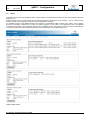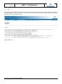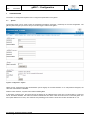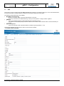
1
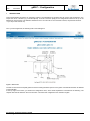
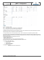
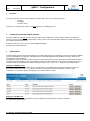
Version: 4.53 Date: 26.02.2015 User Manual gMUC – Configuration gMUC User Manual Dr. Neuhaus Telekommunikation GmbH Page 1/30 Version: 4.53 Date: 26.02.2015 User Manual gMUC – Configuration Contents 1 2 Introduction .............................................................................................................................................................................. 4 Status ...................................................................................................................................................................................... 5 2.1 System ............................................................................................................................................................................. 5 2.2 Meters .............................................................................................................................................................................. 6 2.3 Log ................................................................................................................................................................................... 7 3 Configuration ........................................................................................................................................................................... 8 3.1 System ............................................................................................................................................................................. 8 3.2 WAN ................................................................................................................................................................................. 9 3.3 LAN ................................................................................................................................................................................ 12 3.4 Update ............................................................................................................................................................................ 12 3.4.1 Uploading the firmware ........................................................................................................................................... 12 3.4.2 Activating the firmware ............................................................................................................................................ 13 3.5 Meter .............................................................................................................................................................................. 13 3.5.1 Special Notes for the configuration of a MBUS meter ............................................................................................. 14 3.6 Interfaces ........................................................................................................................................................................ 16 3.7 MODBUS ........................................................................................................................................................................ 17 3.8 MODBUS-SLAVE ........................................................................................................................................................... 18 3.9 Learn-Mode .................................................................................................................................................................... 18 3.10 Automatic Status-Output for wMBUS ............................................................................................................................. 22 3.11 “CHANGED”-Profile........................................................................................................................................................ 22 4 SECURITY ............................................................................................................................................................................ 23 5 Formation rules for W-MBUS address ................................................................................................................................... 23 6 OBIS Mapping ....................................................................................................................................................................... 23 7 Push ...................................................................................................................................................................................... 24 8 Automatic meter configuration and activation ........................................................................................................................ 27 9 Appendix................................................................................................................................................................................ 29 9.1 List of abbreviations........................................................................................................................................................ 29 10 Copyright Statement .......................................................................................................................................................... 30 Dr. Neuhaus Telekommunikation GmbH Page 2/30 Version: 4.53 Date: 26.02.2015 User Manual gMUC – Configuration List of changes since the last version Version 1.00 2.00 Date 20.07.2010 30.08.2010 Who HKE HKE 3.10 3.21 08.03.2011 02.09.2011 19.09.2011 01.10.2011 11.11.2011 12.03.2012 JSC HKE JSC JSC HKE RGR 4.00 4.01 4.50 4.52 4.52 23.10.2012 15.11.2012 29.04.2013 16.12.2014 19.01.2015 RGR GEX HKE IKE IKE 3.00 Chapter Changes since the last version Created - RS232 Interface support - DynDNS configuration / Examples - STUN interval Details Learn mode Push Details Learn mode 3.6 Details Interface configuration 3.7 MODBUS support - support wMBus Mode S - check WAN connectivity (Ping) 3.5 gMUC V2 M-Bus configuration 3.6 gMUC Interface configuration 8 Automatic meter configuration and activation 3.5,3.6, 3.8 MODBUS-SLAVE extension 3.10,3.11 wMBUS Status and “CHANGED” Logger extension Dr. Neuhaus Telekommunikation GmbH Page 3/30 Version: 4.53 Date: 26.02.2015 1 User Manual gMUC – Configuration INTRODUCTION This manual explains the options for configuring a gMUC. The parameters for the gMUC are set using a web configuration. You require the use of a browser (e.g. Internet Explorer). A secure connection (https) to the configuration interface is set up in the address bar in the browser. The default IP address is set to 192.168.186.10. The username is admin, the password is admin. (i.e. https://192.168.168.10). Once you have registered, the following start screen will appear: Figure 1: Start screen The start screen shows the explicit gMUC ID and the existing hardware options for the gMUC. All external interfaces are labeled on the illustration. At the top edge of the screen, you will find the configuration menu, which will be explained in more detail in the following. The chapters after that are based on the menu structure. The entire web configuration was created in English. Dr. Neuhaus Telekommunikation GmbH Page 4/30 Version: 4.53 Date: 26.02.2015 2 User Manual gMUC – Configuration STATUS 1 The Status section provides information on the current status of the gMUC. It cannot be altered . The information available includes status variables, the meters available and the log. 2.1 System This indicates the internal status variables that are currently set in the system. These are system-specific and service-specific variables the number of which depends on the operating mode used (GPRS, DSL) and the hardware. Figure 2: Status - System 1 To alter the parameters, see Chap. 3 Dr. Neuhaus Telekommunikation GmbH Page 5/30 Version: 4.53 Date: 26.02.2015 2.2 User Manual gMUC – Configuration Meters This screen shows a list of the available meters. Further details on the meter are also shown for each entry (address, measured variables, etc.). Before the values from one of the meters are recorded by the gMUC, that meter has to be activated – to do so, click the button marked ‘Activate”, which appears if the meter is not yet registered in the gMUC. For W-MBUS meters, the W-MBUS identifiers are mapped on standardized OBIS numbers in the gMUC. If this mapping process is incomplete or defective for a meter, this will be displayed on the screen. The mapping then has to be adjusted accordingly in the gMUC. If the meter data received from a W-MBUS meter is encrypted, the meter must first be activated (click ‘Activate’), and then store the corresponding AES key in the configuration of the meter (Chapter 3.5). Figure 3: Status - Meter Dr. Neuhaus Telekommunikation GmbH Page 6/30 Version: 4.53 Date: 26.02.2015 2.3 User Manual gMUC – Configuration Log The operating events generated in the system are stored in a log, which can be read out on this screen. Among other things, it provides information on any errors that have occurred and system messages. Click the button marked ‘Delete’ to permanently delete the information currently in the log. Figure 4: Status - Log Dr. Neuhaus Telekommunikation GmbH Page 7/30 Version: 4.53 Date: 26.02.2015 3 User Manual gMUC – Configuration CONFIGURATION The section on Configuration explains how to configure the parameters for the gMUC. 3.1 System The System screen can be used to alter the registration information (username / password) for the web configuration. The gMUC system time (UTC) is set here and you can also trigger a restart of the gMUC. Figure 5: Configuration – System WebUI access configured the client authentication (HTTP Digest) for the WAN interface. If no user/password assigned, the client side authentication is disabled. With the button "Restart", a system reboot will be initiated gMUC In the section "System Time", the system time of the gMUC can be called/changed. If the time is synchronized by a NTP time server, the field is disabled. The value "local offset" indicates the time offset of the current time zone in which the gMUC is in hours (time difference from UTC). The automatic use (switching) from summer / winter time can also be switched on / off. Dr. Neuhaus Telekommunikation GmbH Page 8/30 Version: 4.53 Date: 26.02.2015 3.2 User Manual gMUC – Configuration WAN This screen is used to configure the WAN (Wide Area Network) interface for the gMUC. Before you can use the WAN interface, it has to be activated. The WAN interface is always the rear Ethernet RJ45 jack on the gMUC. The following general parameters are available: Max WAN connection delay Maximum connection delay to start the WAN interface in seconds In this way, the load can be distributed during a startup for the operation of a large number of gMUCs. gMUC ID The ID of the individual gMUC to differentiate between the different devices If the gMUC ID is left blank (default), the MAC address in Hex notation without the dots will be used automatically as the ID WAN restart period Time in seconds after which the WAN interface is restarted cyclically (default: 0 = off) There are four different ways in which the device can be reached via WAN: IP, PPPoE, DHCP and GPRS. Dr. Neuhaus Telekommunikation GmbH Page 9/30 Version: 4.53 Date: 26.02.2015 User Manual gMUC – Configuration Figure 6: Configuration – WAN IP - In this case, the gMUC can be given a fixed static IP address, at which it can be reached in the WAN network (e.g. Internet/Intranet). As a rule, this configuration is used for testing only. PPPoE This option is used to configure a PPPoE dial-up onto the Internet using DSL technologies. The username and the password for DSL access must be stored here. The gMUC must be connected to a DSL modem with its WAN interface. DHCP In this operating mode, the gMUC is operated on an existing DSL router. The router performs the DSL dial-up itself and has to be configured as the DHCP server. The gMUC then serves as the NAT client “behind” the router and gets its IP parameters (IP address, DNS, etc.) via the DHCP protocol from this router. It is not necessary to configure special parameters in the gMUC. The gMUC must be connected to the router with its WAN interface. GPRS This option is used for the configuration of a GPRS dial-up on the Internet. The gMUC must have a valid SIM card; the SIM-card parameters (PIN, username, password) must be configured accordingly. The network operator’s APN (Access Point Name) also has to be entered. Other general configurations are optional … STUN If a STUN server is configured, the public IP address of the DSL connection can be identified. This is useful in the DHCP operating mode in particular, in which case the public IP address of the DSL router is required. A time interval can be configured (in seconds) where he periodically STUN server is queried, which is necessary if the public Internet can change address (forced separation in DSL access) DNS This is where you can configure a static DNS server for an Internet name resolution. As a rule, this only makes sense in the IP operating mode because the DNS server is configured automatically in the system in all the other cases (PPPoE, DHCP, GPRS). DynDNS This is where you can configure a DynDNS Internet service. This makes it possible to address the gMUC under a fixed symbolic, non-ambiguous name on the Internet instead of using the device’s IP address, which can change under certain circumstances (e.g. new Internet dial-up). The configuration parameters depend individually on the DynDNS service used. The following placeholders are available to define a DynDNS update request in general: The update request cannot contain any "". Dr. Neuhaus Telekommunikation GmbH Page 10/30 User Manual Version: 4.53 Date: 26.02.2015 gMUC – Configuration Placeholders <username> <password> <gmuc-id> <domain> <public-ip> <private-ip> or <local-ip> Meaning DynDNS username DynDNS password gMUC ID DynDNS domain Public Internet IP address (e.g. assigned via PPPoE or STUN) Local IP address (e.g. assigned via fixed IP4 or DHCP) Example of registration with the “dyndns.com“ provider username,password: [email protected],technik12345 domain: gmuc.dnsalias.org update request: -u <username>:<password> -a <public-ip> -h <domain> -S dyndns Example of registration with the “no-ip.com“ provider username,password: [email protected],technik12345 domain: 002569627165.no-ip.org update request: -u <username>:<password> -a <public-ip> -h <domain> -s dynupdate.no-ip.com -S dyndns -g /nic/update?username=<username>&password=<password>&hostname=<domain>&myip=<public-ip> Ping - to check the IP connectivity, servers can be configured to be pinged at configurable intervals up to three servers are adjustable interval defines the period in seconds, a server is pinged length defines the length of the payload repeat defines the number of retries after an unsuccessful ping attempt after timeout seconds a ping request have to be acknowledged after Retrying repeat +1 times on every configured server the WAN connection will be restarted the WAN restart period is random between 1 s and 60 s a repeating disconnect of the WAN connection because of an unsuccessful ping session results in doubling the WAN restart period once the WAN restart period is higher than 3600 s, the increasing is stopped NTP - The NTP protocol is used to synchronize the gMUC time. - It is possible to enter the NTP server and the interval, in which a synchronization process takes place. - As a rule, the gMUC uses UTC (Universal Time Coordinated) time internally. Remark In the Group 'NTP', the NTP servers are specified, and the interval at which a synchronization is performed. The set NTP period cannot be set exactly to any second, but only on powers of two. 24 = 16, 25 = 32, 26 = 64, 27 = 128, 28 = 256, 29 = 512, 210 = 1024, 211 = 2048 , 212 = 4096 ... 217 The gMUC completes the calculated power, i.e. be set to 2048 sec 3600 sec (34min). The next highest value is 4096 seconds (68 min). The maximum value is 217 seconds. If it is determined that the system time is stable, the round trip time is automatically increased by the NTP service NTP standard algorithm. The NTP service regulates the system clock and ensures that no time jumps occur due to the synchronization! Dr. Neuhaus Telekommunikation GmbH Page 11/30 Version: 4.53 Date: 26.02.2015 3.3 User Manual gMUC – Configuration LAN This screen is used to configure the data for the service interface (front Ethernet interface). The IP address and the network mask can be configured. The service interface is a prerequisite for web access. The default setting for the IP address is configured to 192.168.168.10. Figure 7: Configuration – LAN 3.4 Update Updates are available for the firmware on the gMUC. This is done in two steps: Upload and activate the firmware. The firmware versions already loaded onto the device will also appear on the list. A total of up to three different firmware versions can be stored on the device. The firmware version that initially comes with the device cannot be overwritten or deleted. The user can choose from between two versions by activating the desired version. Figure 8: Configuration - Update 3.4.1 Uploading the firmware To upload a new firmware program onto the device, you must select a firmware file delivered by the manufacturer on the input screen. Once the file has been selected, the upload process must be started. Once the upload has been successfully completed, the new firmware version will appear on the list of firmware versions. Should an error occur, an error message will appear on the screen. Dr. Neuhaus Telekommunikation GmbH Page 12/30 Version: 4.53 Date: 26.02.2015 User Manual gMUC – Configuration The firmware that was uploaded is now available on the device and ready for activation. Up to two individual firmware files can be uploaded. 3.4.2 Activating the firmware After the new firmware has been uploaded, it is still inactive – the previous version is the one that is active. If you want to activate the new firmware, you have to click the corresponding ‘Activate’ button in the list to replace the previous version with the newly activated one. The system will be restarted automatically. This completes the activation process. The previous version of the firmware will remained stored on the device and can be reactivated at any time. Only one version of the firmware can be active at any one time. Once the firmware has been activated, the gMUC will not be available again until the restart has been completed. 3.5 Meter This is the screen you use to add meters and to configure meters that have already been activated (cf. Chap. 2.2). The following information must be provided for new meters only: the identification of the meter (meter ID) the medium recorded (short form) the manufacturer (short form) configuration parameters (interface, protocol, technical bus-address, special interface parameter) The following information can also be included for new and existing meters: the interface via which the meter can be reached a key for the secure connection to the meter (optionally in Hex notation e.g. 01.02.03……..) one or more loggers, which describe the measurements recorded Several loggers can be added to a meter, configured and also removed from the meter. The following values must be entered for a logger: - the logger name (the following are already predefined: 15m, 1d, 1h, 1m, 1mon) - the logger time interval (the following are defined: MINUTE, 15 MINUTE, HOUR, DAY, WEEK, MONTH, YEAR) - the max. size (number of entries) for the logger - the OBIS ID for the measurement to be recorded - the PUSH parameters The following parameters are valid for options: Interface name: RS485, RS232, WMBUS Protocol: 1107, SML, MBUS, DLMS, MODBUS Baudrate: Baudrate=300[,600,1200,2400,9600,19200,38400,57600,115200] Timesource: NTP,meter ADDR: xxxxxx (e.g. RS485 bus address, WMBUS-MeterID, MODBUS address) Sensor: [1..64] Example: RS485,1107,Baudrate=300,NTP,ADDR=00000001 Example: WMBUS,MBUS,ADDR=38000226 Example: RS232,SML,Baudrate=9600,meter,ADDR=01A815671833020102 Example: RS485,DLMS,Baudrate=115200,NTP,Hdlc=100.17.1,Password=12345678 Example: RS485,MODBUS,ADDR=2,Baudrate=9600,Register0=HR:0:uint16,Register1=HR:1:uint16 Dr. Neuhaus Telekommunikation GmbH Page 13/30 Version: 4.53 Date: 26.02.2015 User Manual gMUC – Configuration Figure 9: Configuration – Meter 3.5.1 Special Notes for the configuration of a MBUS meter The protocol MBUS requires MUS V2 and additional hardware. The MBUS specification defines two types of addressing a meter. primary addressing and secondary addressing. Most meters support both types. MUS V2 supports only secondary addressing. To configure MBUS meter the secondary address (4 bytes – BCD encoded) have to be specified in parameter ADDR. The secondary address corresponds to the serial number printed on the meter. Leading zeros have to be filled up to a size of 8 digits. When using secondary addressing the following three parameters have to be correct: secondary address, medium, meter software version (0-255). In case of unknown parameter, placeholder can be used. - secondary address: FFFFFFFF - medium: X (intern 0xFF) - meter software version: keep empty or 255 (decimal representation) Every meter responses, whose own parameters matches with configured ones. For example, a meter with the data secondary address: 2547659 baud rate: 2400 meter software version: 0 number of responses: 1 is configured as followed: Baudrate=2500,Version=0,Responses=1 Dr. Neuhaus Telekommunikation GmbH Page 14/30 Version: 4.53 Date: 26.02.2015 User Manual gMUC – Configuration Some meters responses with more than one messages. To get additional responses the optional parameter Responses have to configured. The default setting is Responses=1. The number of responses a meter provided, can be found in the datasheet. Commands send to a meter, will not be responded in the same way for different meters. The optional parameter OPTIONS handle those deviations. OPTIONS value 01 02 definition Meters do not response on an init command (i.e. Carlo Gavazzi Controls (EM33-DIN)). With OPTIONS=01 such meters are requested correctly. Some Meters responses with large data packets (i. e. Landis+Gyr (UH50-A38C-DE00-B)) A configured baud rate less than 2400 baud results in a timeout. With OPTIONS=02 the timeout is increased for the specific meter. The Elster MBUS PR6 meter responds to the command SND_NKE whether this meter has been addressed or not. Meters that can provide more than one responses, require the command SND_NKE. Consequently the simultaneous operation of a meter, that provides more than one response, and the PR6 module does not work reliably. Alternatively, meters have to be configured with Responses=1 to work in combination with a PR6 module. Dr. Neuhaus Telekommunikation GmbH Page 15/30 User Manual Version: 4.53 Date: 26.02.2015 3.6 gMUC – Configuration Interfaces 2 The Interfaces screen lists the meter interfaces available on (RS485 / WMBUS ). Additional options can be indicated for each of these interfaces. Figure 10: Configuration - Interfaces The options provided for an interface must be separated from each other by commas. Possible options include: Interface type Option Meaning RS485 RS232 Learn=1107 Learn=SML Learn=DLMS Automatic recognition of inactive meters with indication of the protocol: 1107 = Recognition of 1107 meters on the RS485 SML = Recognition of SML meters on the RS485 / RS232 DLMS = Recognition of DLMS meters on the RS485 Speed of the interface in baud in Learn Mode; for 1107 meters, this is the starting baud rate (300, 1200, 2400,….) Query interval in seconds (only multiples of 60 seconds allowed) Password (ASCII) when using DLMS meter HDLC address when using DLMS meter (default 100.17.1) D = mode D when using 1107 meter C = mode C when using 1107 meter (default) Ciase = when using Sagem/DLMS meter MODBUS-SLAVE when using gMUC as slave for Modbus Meter password when using DLMS meter Dataregister definition when using MODBUS sensor [00..FF] gMUC Slave address used in Modbus-Slave mode [7N1..8N1] Uart Format used in Modbus-Slave mode Automatic recognition of inactive WMBUS meters The protocol (MBUS or SML) of the payload is automatically recognized by the WMBUS and does not have to be entered. T = wMBus module works in T-Mode (default) S = wMBus module works in S-Mode Speed of the interface in baud (300,600,1200,2400,4800,9600) Baudrate=xx Query=xx Password=xx Hdlc=xx.yy.zz Mode= WMBUS Password= Register0..n= SlaveAddr=xx Format=xxx Learn Mode= MBUS 2 Baudrate=xx Wireless M-Bus Dr. Neuhaus Telekommunikation GmbH Page 16/30 User Manual Version: 4.53 Date: 26.02.2015 gMUC – Configuration Responses=xx OPTIONS=xx Number of MBus responses on a meter request default: Responses=1 optional MBus parameter to control protocol exceptions Example configurations meter typ meter options Interface options 1107 to RS485 RS485,1107,ADDR=12345678,Baudrate=9600,Mode=C Query=60 SML to RS232 RS232,SML,ADDR=12345678,Baudrate=9600 DLMS to RS485 RS485,DLMS,ADDR=12345678,Hdlc=100.17.1,Baudrate=115200,Password=xxxxx Query=60 DLMS/Sagem an RS485 (with Discovery) WMBUS RS485,DLMS,ADDR=12345678,Mode=Ciase,Baudrate=9600,Password=xxxx, Hdlc=100.17.1 Query=60 MODBUS to RS485 RS485,MODBUS,ADDR=1,Baudrate=19200, Register0=IR:0:floatinverse, Register1=IR:2:floatinverse 3.7 WMBUS,MBUS,ADDR=12345678 Query=60 MODBUS The query of certains registers of a MODBUS sensor must be configured in the meter options using the parameters Register0..n=function:address:format: Query function (HR - holding register, IR - input register) Register start-address (integer) Register data format (uint16, uint32, float, floatinverse) Syntax: Register[0..n]=function[HR,IR]:address:format Example: Register0=HR:0:uint16, Query of the holding register with start adrdess 0, data format integer Example: Register1=IR:2:floatinverse, Query of the input register with start address 2, data format floatinverse complete meter options for the query of two registers: RS485,MODBUS,ADDR=1,Baudrate=19200,Register0=IR:0:floatinverse,Register1=IR:2:floatinverse The registers must be mapped in the OIDMAP (chapter 6) to the Obis numbering system. Dr. Neuhaus Telekommunikation GmbH Page 17/30 Version: 4.53 Date: 26.02.2015 3.8 User Manual gMUC – Configuration MODBUS-SLAVE Modbus-Slave mode can be activated by setting Mode=MODBUS-SLAVE under configuration->interfaces->RS485->options. This mode can be used, to transport specific MBUS or WMBUS data over modbus on specific requests and can be parametrized by these options: SlaveAddr – which defines the RTU slave address for the gMUC (default: 01) Format – defines the RTU format (default: 8N1) Baudrate – defines the RTU baudrate (9600, 19200, 38400, default: 9600) Should an invalid Baudrate be set, then the default value will be used. If any of these options were not used, then the corresponding option would be automatically use the default value. To transport the specified data, first some ‘Sensor’(s) can be defined. This can be done under configuration->meters->options. Meter can be marked as sensors, by setting the ‘Sensor’ parameter. This parameter definies the sensor number, which indirectly defines the address area for this sensor. Each Sensor value has a range of 100 register addresses. For example: Sensor=1 will be automatically mapped to register addresses 100-199, Sensor=2 will be mapped to register addresses 200-299, Sensor=3 will be mapped to register addresses 300-399 .. to a maximum of Sensor=64, which will be mapped to register addresses 6400-6499. Sensor=0 is an invalid value. Register addresses 1-99 are used for system variables. Register address 1 is used for GPRS modem RSSI value, other register addresses of system variables are reserved for future use. If there should be meters, which were not defined as sensor(s), they will be automatically initialized with the next free internal sensor-id. The internal sensor-id will not be reflected (saved) back, so that on each re-initialization the sensor-id for those meters can change. Only meters, which were marked with the ‘Sensor’ parameter will always have a constant sensor-id. When the MODBUS-SLAVE driver was correctly defined, then the specified sensor data can be requested by using read holding register commands over modbus. In cases of specific errors (modbus exeption codes) of the request, appropriate exception responses will be sent. The start address in the request of read holding register for sensors will be incremented by 1. So the requested adress 100 for example, will return the value of adress 101. Write single register commando is supported and echos to any command that uses function code 06. The specified register address (0x7F7F) with the value 0xA55A will cause a system reboot. Total status values can be read using read discrete input. To get these values, the sensors in the requested range must have been defined, otherwise an exeption response will be sent. Some status values in the webui, have no value, but text. MODBUS-SLAVE definies specific values for these cases: 0x0000 – for Status “ok” 0xF000 – for Status “no reaction from meter,..” 0xFF00 – for all other pure text status values 0x00xx – for Status “error: ..” (in case, there is a hexadecimal value after error:) xx stands for this hexadecimal value 3.9 Learn-Mode The learn mode is used for automatic detection of not activated meters. Notice the following facts when using the learn mode: 1107 While the learn mode is active only one meter should be connected via RS485, otherwise there will be collisions on the bus and no data can be read out. This meter will be requested with an ‚empty’ address. If the answer contains the real address it will be read out. After detection of the meter, the learn mode has to be switched off. Some 1107 meters do not support this type of request (empty address). In this case the meter has to be added manually. DLMS The DLMS meters of the manufacturer Sagem use a further protocol (CIASE). With this protocol the Sagem DLMS meters connected to the RS485 are detected. While detection, the meters recieve an MAC address, i.e. the learn mode is necessary for Dr. Neuhaus Telekommunikation GmbH Page 18/30 Version: 4.53 Date: 26.02.2015 User Manual gMUC – Configuration the first start. To ensure this, add Learn=DLMS to the interface configuration (s. Figure 10). After a successful detection/activation of the new Sagem meter, the learn mode option has to be removed from the interface configuration. The learn mode is also activated automatically on faulty DLMS requests and manually meter configuration for a short time. Dr. Neuhaus Telekommunikation GmbH Page 19/30 Version: 4.53 Date: 26.02.2015 User Manual gMUC – Configuration The whole chain of the detection is described here: 1. Connection of the Sagem meter(s) over the RS485 interface 2. activation of the learn mode in the interface configuration (s. Figure 10) 3. wait for the detection of the new meter, check by refreshing the page Status – Meter, e. g.: Figure 11: detected Sagem DLMS meter The learn mode is now automatically deactivated 4. Activation of the new meter and adjustment of the logger on the page Configuration – Meter Figure 12: configuration of the new Sagem DLMS meter the follwing OBIS-Ids are available: Power: 1-0:1.6.0 Energy: 1-0:1.8.0 Dr. Neuhaus Telekommunikation GmbH Page 20/30 Version: 4.53 Date: 26.02.2015 5. User Manual gMUC – Configuration After the next request of the meter ist values are shown on the page STATUS\meter: Figure 13: values of the new Sagem DLMS meter 6. deactivation of the learn mode in the interface configuration (s. Figure 10) by removing the option Learn=DLMS Dr. Neuhaus Telekommunikation GmbH Page 21/30 Version: 4.53 Date: 26.02.2015 3.10 User Manual gMUC – Configuration Automatic Status-Output for wMBUS The wMBUS status byte will be added as an extra measurement to the data record, before this record will be send to the logger profiles. This means, that each datapoint (in wMBUS) will have this additional (to other measurements) value of the status byte from the wMBUS telegram. It can be mapped similar to other dif/vif to obis combinations, but it uses/needs no dif/vif at all and has a hardcoded obisid representation F-F:F.F.F, so that only “Name” and “OBIS” have to be configured under obis-map. The wMBUS status byte will be shown in webui under meter -> status for each wMBUS meter, also if it’s not configured. The following chapter “CHANGED”-Profile introduce a possible configuration to persist/log of this status value. Figure 14: Status logging for wMBUS 3.11 “CHANGED”-Profile This profile can be configurated for saving measurment values, which should be logged only on changes. The “CHANGED” logger has no time trigger (intervall), so it’s directly triggered when current value is not equal to the last saved value. The functionality of this logger, described on the example for logging status/error from wMBUS messages: a logger of type “CHANGED” is configured, that should save the obisid “F-F:F.F.F” this logger will save the sequential changes of the status byte and can be reached via push and poll on the WAN interface if this logger will be configurated with PUSH, for example with push interval MINUTE, so the PUSH will be triggered maximum once in a minute and would contains all changed values for this obis, obtained in this minute (plus possible old values which were not pushed previously – default PUSH functionality) a PUSH will only be triggered if the logged value has changed if there were no changes within the minute, then there will be no PUSH the PUSH trigger itself is time triggered (smallest interval = 1min) notice: the obisid “F-F:F.F.F” can also be used in context of a standard interval logger (so it would be saved, as “normal” measurement) Dr. Neuhaus Telekommunikation GmbH Page 22/30 Version: 4.53 Date: 26.02.2015 4 User Manual gMUC – Configuration SECURITY For safety reasons, there is an active firewall on the gMUC that routes only the following IP ports: 80 (http) 443 (https) 22 (SSH, SFTP) This means, for example, that a gMUC does not respond to an ICMP (ping) query. 5 FORMATION RULES FOR W-MBUS ADDRESS The meter address is read directly on the meter and used for the configuration. It must consist of 8 digits. If the address is shorter, it must be preceded by the corresponding number of zeros. The internal W-MBUS address is created on the basis of the medium/manufacturer/meter ID. Example: 01.2D.2C.11.78.67.14.01.02 (internal WMBUS address) Corresponds to: E/KAM/14677811 6 OBIS MAPPING Inside the gMUC all meter data will be managed by a number OBIS number. This numbering system is for example in WMBUS protocol and MODBUS not supported. The DLMS protocol need additional parameters (attributes and class), that must be configured for a meter data query. The mapping is done by specifying the protocol (protocol=mbus,dlms,modbus) and by special protocol parameters that lead to compliance with OBIS mapping to the specified OBIS number/name. When mapping, the unit (unit) and scaling (scale) of the scaler measured value can be specified. The scaler is using the formula: value = value * 10 applied to the measured value. Mapping of a WMBUS meter: For a OBIS number/name the corresponding Dif, Vif, parameters of the WMBUS protocol must be configured. These are specified in hexadecimal notation. e.g. dif=07,vif=03.3B By configuration of optional parameter „medium=“ and/or „meteraddr=“ it is possible to specify the mapping for an specific medium or meter. Mapping of a DLMS meter: For a OBIS number/name the corresponding class and attribute of the DLMS protocol must be configured. e.g. class=0003, attribute=02.03 Dr. Neuhaus Telekommunikation GmbH Page 23/30 Version: 4.53 Date: 26.02.2015 User Manual gMUC – Configuration Mapping of a MODBUS Sensor: For a OBIS number/name the corresponding bus-address of the sensor and the MODBUS register with specification of function (HR - holding register, IR - input register) and start address must be configured. e.g. meteraddr=1,register=HR:2 7 PUSH The Push page configured the Push jobs of the gMUC. The Push feature will be periodically sent meter data from the gMUC to an FTP or HTTP server. The transmitted data is sent in XML structures. Using FTP Push, a XML file will be sent to the FTP server. Using HTTP Push, the same XML data will be sent as content of the html file. The push XML data structures are described in the document gMUC_XML_Interface_vEN.doc. Dr. Neuhaus Telekommunikation GmbH Page 24/30 Version: 4.53 Date: 26.02.2015 User Manual gMUC – Configuration Configuration of an push target: NAME symbolic name of the PUSH target, using for referencing on meter configuration ON global activation/deactivation of the Push target HOST DNS-Name or IP- address of the Push servers with port number PROTOCOLL FTP or HTTP USER/PASSWORD Client authentication of the Push server (optional) ENTRY COUNT Maximum number of measurements in one push packet, this value determines the max. XML file size of a single push. MAX. RUNTIME Push Timeout in seconds For the configuration of the URI (FTP file name, HTTP query string) wildcards are available with which one can realize a dynamic run-time implementation. The configuration of the URI is optional and must be coordinated with the server. When you push the FTP directory, the structure of the given file name on the server is automatically created. Dr. Neuhaus Telekommunikation GmbH Page 25/30 Version: 4.53 Date: 26.02.2015 <GMUC-ID> User Manual gMUC – Configuration <GMUC-NAME> <MEDIUM> <MFCT> <METER-ADDR> <METER-ID> <PROFILE> <PUSHTIME> <PUSHTIME-TXT> gMUC: Device ID / name Meter: medium / manufacturer / address / ID Data Logger Profile (1m, 15m, 1h, 1d, 1mon) Push time: second / Text In the meter configuration, each logger profile will be assigned to a push job. Is this configured, the meter data of this logger will be pushed to the corresponding push target. The push interval of a logger can be configured individually. It need not be identical to the recording interval (period). E.g. In the example below, the 15 minute values are pushed all hours. In the corresponding XML files you will find 4 data points. To the push interval a random offset time in minutes can be configured. I.e. Push the actual time is a random time offset between 0 .... Offset added to it. Thus, a load distribution for the push servers are achieved when using many of the same pu sh gMUC's interval and push server. The offset can have a maximum size of the push interval of the logger, but not greater than 300 minutes. The Push of every meter can be enabled / disabled loggers across. It is also possible to enable/disable the push for every single logger (check box). If the checkbox RAW enabled, the raw protocol data (undecoded) received from the meter will be append to the XML data structures. Push logger configuration of a meter Comment: When using the FTP protocol (http://en.wikipedia.org/wiki/Ftp), the passive mode is used. The EPSV command will be used for that. The gMUC initiated all TCP-connections to the FTP Server. Dr. Neuhaus Telekommunikation GmbH Page 26/30 Version: 4.53 Date: 26.02.2015 8 User Manual gMUC – Configuration AUTOMATIC METER CONFIGURATION AND ACTIVATION In the gMUC, a meter template can be configured for automatically activating and configuration of meters Plug und Play. In the meter template are all necessary parameters for the - Meter configurations (manufacturer ID, Key, ...) - Logger configurations (period, Obis number, count, push, ...) - Push target configurations (host, protocol, ...) stored, which are necessary for operation in the gMUC. The template can be configured via the Web configuration page CONFIGURATION/template or via the XML/setconfig interface. A selected template is always used internally in gMUC when 1. a meter data packet can’t be assigned to any activated meter and 2. the configured manufacturer-ID (MFCT) of the template matches with the meter manufacturer-ID of the received data packet. In this case a new meter will be configured and activated in the gMUC. All necessary meter parameters be used from the meter data packet (meter number) as well as from the template (logger configuration, push configuration). Furthermore, a push target is created and/or configured when to corresponding entries are available in the template. This Push target is linked internally to the new meter. Dr. Neuhaus Telekommunikation GmbH Page 27/30 Version: 4.53 Date: 26.02.2015 User Manual gMUC – Configuration Dr. Neuhaus Telekommunikation GmbH Page 28/30 Version: 4.53 Date: 26.02.2015 9 9.1 User Manual gMUC – Configuration APPENDIX List of abbreviations Abbreviation Meaning APN Access Point Name DHCP Dynamic Host Configuration Protocol DLMS Device Language Message Specification DNS Domain Name System DynDNS/DDNS dynamic Domain-Name-System GPRS General Packet Radio Service GSM Global System for Mobile Communications IP Internet Protocol LAN Local Area Network gMUC Multi Utility Gateway NAT Network Address Translation NTP Network Time Protocol PIN Personal Identification Number PPPoE Point-to-Point Protocol over Ethernet SIM Subscriber Identity Module STUN Session Traversal Utilities for NAT WAN Wide Area Network MBUS / M-Bus wired Meter Bus WMBUS / wMBUS wireless Meter Bus Dr. Neuhaus Telekommunikation GmbH Page 29/30 User Manual Version: 4.53 Date: 26.02.2015 10 gMUC – Configuration COPYRIGHT STATEMENT The information released in this publication is under copyright. Any translation, reprints, duplication and/or storage in dataprocessing systems requires the express consent of Dr. Neuhaus Telekommunikation GmbH. © 2015 Dr. Neuhaus Telekommunikation GmbH All rights reserved. Dr. Neuhaus Telekommunikation GmbH Papenreye 65 D-22453 Hamburg Germany Internet: http://www.neuhaus.de Subject to technical modification gMUC is a trademark of Dr. Neuhaus Telekommunikation GmbH. All other trademarks and product names are the trademarks, registered trademarks or product names of the respective owners. Dr. Neuhaus Telekommunikation GmbH renders all deliveries and services on the basis of the currently valid version of the company’s General Conditions of Contract. All information is provided on the basis of the manufacturer’s information. No warranty or liability for any incorrect information and omissions. The description of the specifications in this manual does not constitute a contract. Doc. No.: 8213AD012 / Version 4.53 Dr. Neuhaus Telekommunikation GmbH Page 30/30