1
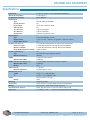
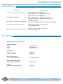
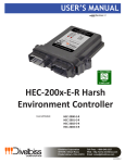
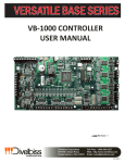
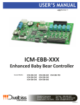
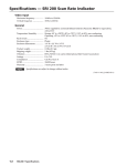
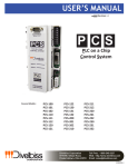
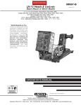
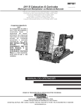
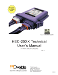
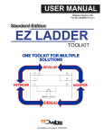
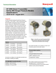
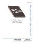
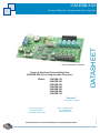
ICM-EBB-XXX
PLC on a Chip Patent 7,299,099
Technical Datasheet Enhanced Baby Bear
(ICM-EBB-XXX) Series Programmable Controllers
Models:
ICM-EBB-100
ICM-EBB-200
ICM-EBB-300
ICM-EBB-400
ICM-EBB-500
ICM-EBB-600
ICM-EBB-700
DATASHEET
Enhanced Baby Bear Programmable Logic Controllers
Revision 7
Release Date 1/31/2007
Phone: 1-800-245-2327
Fax: 740-694-9035
www.divelbiss.com
All Specifications & InformationSubject to Change without Notice
2004007.7
Divelbiss Corporation
9778 Mt. Gilead Rd.
Fredericktown, Ohio 43019
ICM-EBB-XXX DATASHEET
Table of Contents
Title
Pages
Description................................................................................3
Features.....................................................................................3
Programming............................................................................3
Connections.............................................................................4
Input Power..............................................................................4
Digital Input / Output Terminal Strips.........................................5
Digital Inputs............................................................................5
Digital Outputs........................................................................6
Counter Input...........................................................................6
CAN Interface Port..................................................................7
Input / Output Expansion.........................................................7-9
COM 0 - Programming Port.........................................................9
COM 1 - Optional Serial Port Modules....................................9-10
Real Time Clock.....................................................................11
Specifications.........................................................................12
EZ LADDER Specific Information.........................................13-14
Troubleshooting.....................................................................15
Accessories.....................................................................15
WARNING!
The ICM-EBB-XXX, as with programmable controllers,
must not be used alone in applications which would be
hazardous to personnel in the event of failure of this
device. Precautions must be taken by the user to provide
mechanical and/or electrical safeguards external to this
device. This device is NOT APPROVED for domestic or
human medical use.
ICM-EBB-XXX Datasheet
Document #: 2004007.7.pdf
Page 1 of 15
Divelbiss Corporation 9778 Mt. Gilead Rd. Fredericktown, Ohio 43019 1-800-245-2327 www.divelbiss.com
ICM-EBB-XXX DATASHEET
The Enhanced Baby Bear Series of programmable logic controllers builds on the rugged reliability and features of the Baby
Bear Bones and adds even more versatility and features.
Designed with PLC on a Chip, the EBB-XXX is easy to use
and program using EZ LADDER®, providing complete control
over unlimited control applications.
The EBB-XXX programs in Ladder Diagram with additional
function blocks. The ICM-EBB-XXX has identical dimensions
and mounting as the original Baby Bear Bones
Features
Model
Flash
Memory
On-board I/O
I/O
Expansion Type
CAN
Port
Real Time Counter
Clock
Input
EBB-100
128 K
5 Inputs 10-32VDC /
10-30VAC RMS
5 Relay Outputs
None
No
No
No
Programming
Port, RS232
None
12 VDC or
*10VAC
EBB-200
128 K
5 Inputs 10-32VDC /
10-30VAC RMS
5 Relay Outputs
None
No
No
Yes
Programming
Port, RS232
None
12 VDC or
*10VAC
EBB-300
128 K
5 Inputs 10-32VDC /
10-30VAC RMS
5 Relay Outputs
None
No
Yes
Yes
Programming
Port, RS232
None
12 VDC or
*10VAC
EBB-400
128 K
5 Inputs 10-32VDC /
10-30VAC RMS
5 Relay Outputs
Baby Bear I/O Expander
( 8 DC Inputs 8 Relay
Outputs)
No
Yes
Yes
Programming
Port, RS232
None
12 VDC or
*10VAC
EBB-500
128 K
5 Inputs 10-32VDC /
10-30VAC RMS
5 Relay Outputs
High Density I/O
Expanders ( 120 Inputs
120 Outputs)
No
Yes
Yes
Programming
Port, RS232
None
12 VDC or
*10VAC
EBB-600
256 K
5 Inputs 10-32VDC /
10-30VAC RMS
5 Relay Outputs
Baby Bear I/O Expander
( 8 DC Inputs 8 Relay
Outputs)
Yes
Yes
Yes
Programming
Port, RS232
**RS 232,
**RS422,
or **RS 485
12 VDC or
*10VAC
EBB-700
256 K
5 Inputs 10-32VDC /
10-30VAC RMS
5 Relay Outputs
High Density I/O
Expanders ( 120 Inputs
120 Outputs)
Yes
Yes
Yes
Programming
Port, RS232
**RS 232,
**RS422,
or **RS 485
12 VDC or
*10VAC
Comport 1
Comport 2 Board Power
* with optionally purchased transformer.
** with optionally purchased serial port module. Specify RS232, RS422 or RS485.
Programming
The ICM-EBB-XXX Series PLCs program in Ladder Diagram using Divelbiss’ EZ LADDER®, a Ladder Diagram
Development Platform. Divelbiss’ EZ LADDER® parallels the IEC-61131 standard and provide an easy to use interface.
After a ladder diagram program is developed, it is downloaded to the Enhanced Baby Bear using a serial port.
Once the download is complete, the EBB is successfully programmed and begins executing the program. The program is stored on non-volatile FLASH memory and is automatically executed on power up.
Refer to the EZ LADDER User’s Manual for more detail on creating ladder diagram programs, connecting to targets
and downloading the program to targets.
ICM-EBB-XXX Datasheet
Document #: 2004007.7.pdf
Page 2 of 15
Divelbiss Corporation 9778 Mt. Gilead Rd. Fredericktown, Ohio 43019 1-800-245-2327 www.divelbiss.com
ICM-EBB-XXX DATASHEET
Connections
Board Power
Input 12 VDC
or 10 VAC
COM 1
Optional
HDIO
Power
Optional
Battery
HDIO
Data
Optional
Digital Outputs, Relay (5)
Rated 5 Amps
Solid-state
Fuse
Power
OK LED
Output LED Indicators
ICM-EBB-IO-54P and
ICM-EBB-IO-20P
Expansion Port
Optional
Input LED Indicators
Programming
Port - COM 0
Watchdog
LED
CAN Port
Optional
Digital Inputs, Isolated (5)
Rated 10-42VDC or VAC
Counter Input
Optional
Input Power
The ICM-EBB -XXX may be powered using 10 VAC or 12 VDC. Apply power to CONN1 using the provided input
power cable assembly (PIMS-CA-6). Refer to the input power schematic for details. The transformer shown is
optional.
Divelbiss recommends a step down transformer, 110 VAC to 10 VAC, @ 2A. The transformer may be purchased
from Divelbiss Corporation ( 115VAC Primary: 109-101153, 230VAC Primary: 109-100924)
The ICM-EBB-XXX is protected by a “resettable” fuse. If the fuse should open (the power LED is not illuminated),
remove the input power for 30 seconds and then reconnect the input power. The fuse will automatically reset when
the power is removed.
Input Power Schematic
ICM-EBB-XXX Datasheet
Document #: 2004007.7.pdf
Page 3 of 15
Divelbiss Corporation 9778 Mt. Gilead Rd. Fredericktown, Ohio 43019 1-800-245-2327 www.divelbiss.com
ICM-EBB-XXX DATASHEET
Digital Input / Output Terminal Strips
The input and output terminal strips are “unplugged” and “plugged in” vertically on to connection pins that are located on the EBB-XXX controller board.
Terminal Strip Removal / Insertion
Digital Inputs
Each EBB Series PLC comes standard with five (5) digital inputs, rated 10-42VDC or 10-30VAC RMS. All digital
inputs are optically isolated to provide immunity from noise and interference.
The EBB-XXX inputs are not polarity sensitive.
EZ LADDER input assignments for the EBB-XXX are DI1.03 (Input 0) to DI1.07 (Input 4).
Inputs connections are labeled:
0 - 4 Digital Input Terminals.
+V Unregulated supply (approximately 12 VDC).
This may be used to power sensors and
other devices.
C
Common return for the +V supply.
Typical Input Wiring Diagrams
+AC or
+DC
Sourcing
Input
Device
-AC or
-DC
+AC or
+DC
Isolated
Inputs
Typical Sinking Input Circuit
ICM-EBB-XXX Datasheet
-AC or
-DC
Isolated
Sinking
Input
Device
Inputs
Typical Sourcing Input Circuit
Document #: 2004007.7.pdf
Page 4 of 15
Divelbiss Corporation 9778 Mt. Gilead Rd. Fredericktown, Ohio 43019 1-800-245-2327 www.divelbiss.com
ICM-EBB-XXX DATASHEET
Digital Outputs
Each EBB Series PLC comes standard with five (5) relay outputs, rated 5 Amps.
EZ LADDER output assignments for the EBB-XXX are DO1.03 (Output 0) to DO1.07 (Output 4).
Outputs connections are labeled:
0-4
Relay output contact pins.
Typical Output Wiring Diagrams
AC Only
+AC or
+DC
Load
Relay
Outputs
DC Only
-AC or
-DC
Typical Output Circuit Connection
Counter Input
The ICM-EBB-XXX provides an optional on-board counter input (model dependent). This is an up counter input with
capabilites to 100 KHz. It is ideal for connecting flowmeters and other pulse output devices and sensors.
Connect the CNTR input as shown. The counter is optically isolated to provide immunity from noise and interference.
Pulse Output
Device
Isolated Counter Input
+DC (12V)
Opto-Isolator
Sheild
+
-DC
-
Typical Counter Input Circuit
ICM-EBB-XXX Datasheet
Document #: 2004007.7.pdf
Page 5 of 15
Divelbiss Corporation 9778 Mt. Gilead Rd. Fredericktown, Ohio 43019 1-800-245-2327 www.divelbiss.com
ICM-EBB-XXX DATASHEET
CAN Interface Port
The EBB-XXX provides an optional on-board CAN bus interface port. This port supports the Divelbiss OptiCan and
J1939 Communications.
CAN bus
Device 2
CAN bus
Device 1
CL
Typical 120
Ohm
Typical 120
Ohm
CH
Enhanced Baby
Bear CAN Port
Earth GND
SHIELD
Typical CAN bus Circuit
Input / Output Expansion
In addition to the 5 input and 5 outputs, the EBB-XXX has the ability to expand its I/O (model dependent). The I/O
may be added using two types of additional inputs and outputs.
Baby Bear I/O Expanders
The ICM-EBB-XXX’s I/O can be expanded with an additional 8 Inputs (10-32 VDC) and 8 Relay Outputs using the
ICM-EBB-IO-54RE-P.
Baby Bear Expanders use the EBB-XXX’s CONN8. The ICM-EBB-IO-54P connects directly to CONN8 and is mounted to the EBB-XXX (stackable configuration).
The I/O addressing for the ICM-EBB-IO-54P is always as follows:
Digital Inputs:
DI1.08 - DI1.15
Digital Outputs: DO1.08 - DO1.15
ICM-EBB-XXX
ICM-EBB-IO-54P
ICM-EBB-IO-54RE-P Stackable Mounting
ICM-EBB-XXX Datasheet
Document #: 2004007.7.pdf
Page 6 of 15
Divelbiss Corporation 9778 Mt. Gilead Rd. Fredericktown, Ohio 43019 1-800-245-2327 www.divelbiss.com
ICM-EBB-XXX DATASHEET
PIC-IO-54P vs ICM-EBB-IO-54RE-P
The ICM-EBB-IO-54RE-P is factory configured to operate only with the Enhanced Baby Bear (ICM-EBB-XXX). The PICIO-54P is factory configured to operate only with the original Baby Bear Bones (ICM-BB-12P, ICM-BB-13P, ICM-BB-21P,
ICM-BB-22P). Note: The ICM-EBB-IO-54RE-P now includes factory installed relays.
Should you need to use a PIC-IO-54P with the Enhanced Baby Bear, jumpers will need to be reconfigured on the PIC-IO54P board prior to installation.
To make the jumper changes, the following is required.
1. Soldering Iron
2. 0 Ohm Jumper or Wire Jumper
3. “X-Acto” knife or equivalent.
With the above equipment, follow the diagram below for modifiying the PIC-IO-54P to operate with the Enhanced Baby
Bear.
To Operate with Enhanced Baby Bear:
1. Cut trace between OUT pad and
CENTER pad.
2. Solder Jumper wire from CENTER
pad to IN pad.
JW2 - Provides the Bus Data Source
Factory default from “Center” to “OUT” for
the original Baby Bear Bones operation.
ICM-EBB-XXX Datasheet
Document #: 2004007.7.pdf
Page 7 of 15
Divelbiss Corporation 9778 Mt. Gilead Rd. Fredericktown, Ohio 43019 1-800-245-2327 www.divelbiss.com
ICM-EBB-XXX DATASHEET
High Density I/O Expanders
The EBB-XXX’s I/O can be expanded with up to an additional 120 Inputs and 120 Outputs using the ICM-HDIO-XX
series I/O Expander boards. The ICM-HDIO-XX series provides a wide range of input and output types and voltages.
High Density I/O Expanders use the EBB-XXX’s CONN6 (for data) and CONN3 (for power). These connections are
made via cables. The ICM-HDIO-XX boards are din rail mounted and have addressible addresses.
The I/O addressing for the ICM-HDIO-XX are as follows:
Digital Inputs:
DI0.00 - DI0.15
DI1.00 - DI1.07 are used on board the ICM-EBB-XX and are NOT valid.
DI1.08 - DI7.15
Digital Outputs: DO0.00 - DO0.15
DO1.00 - DO1.07 are used on board the ICM-EBB-XX and are NOT valid.
DO1.08 - DO7.15
COM 0 (Programming Port)
The EBB-XXX is programmed via COM 0. This RS232 serial port is only to be used for programming using Divelbiss’
EZ LADDER. This is not a general purpose port. A null modem cable should be used to connect with COM 0. This
cable may be purchased from Divelbiss (use Part Number: ICM-CA-34).
RS232 Serial Port Module
Pin
ID
1
2
3
4
5
6
7
8
9
-RX
TX
-GND
-RTS
CTS
--
Description
No Connect
Receive Data
Transmit Data
No Connect
Signal Ground
No Connect
Request To Send
Clear To Send
No Connect
COM 0 - Serial Port Pin-Out
COM 1 (Optional)
The ICM-EBB-XXX (256K Models) have the option of an additional serial port. This port may be ordered as an
RS232, RS422 or an RS485 interface. This port supports Modbus Slave.
This serial port is a plug-in module that connects to the ICM-EBB-XXX COM1 connector. The optional serial port
module mounts to the EBB-XXX vertically using provided hardware. See the Serial Port Module Mounting diagram
and Serial Port Pin-Outs for more detail.
Serial Port Module Part Numbers:
RS232 Module
RS422 Module
RS485 Module
ICM-EBB-XXX Datasheet
ICM-EBB-RS232
ICM-EBB-RS422
ICM-EBB-RS485
Document #: 2004007.7.pdf
Page 8 of 15
Divelbiss Corporation 9778 Mt. Gilead Rd. Fredericktown, Ohio 43019 1-800-245-2327 www.divelbiss.com
ICM-EBB-XXX DATASHEET
RS232 Serial Port Module
Pin
ID
1
2
3
4
5
6
7
8
9
-RX
TX
-GND
-RTS
---
Description
RS422 Serial Port Module
Pin
ID
1
2
3
4
5
6
7
8
9
TX--RXGND
RX+
--TX+
No Connect
Receive Data
Transmit Data
No Connect
Signal Ground
No Connect
Request To Send
No Connect
No Connect
Description
Transmit Data (-)
No Connect
No Connect
Receive Data (-)
Signal Ground
Receive Data (+)
No Connect
No Connect
Transmit Data (+)
RS485 Serial Port Module
Pin
ID
Description
1
2
3
4
5
6
7
8
9
TX---GND
---TX+
Data (-)
No Connect
No Connect
No Connect
Signal Ground
No Connect
No Connect
No Connect
Data (+)
COM 1 - Serial Port Module Pin-Outs
Serial Port Module
ICM-EBB-XXX
Serial Port Module Mounting
ICM-EBB-XXX Datasheet
Document #: 2004007.7.pdf
Page 9 of 15
Divelbiss Corporation 9778 Mt. Gilead Rd. Fredericktown, Ohio 43019 1-800-245-2327 www.divelbiss.com
ICM-EBB-XXX DATASHEET
Real Time Clock
The EBB-XXX includes an optional Real Time Clock. The real time clock (after set) provides Month, Day, Day of the
Week, Year, Hour, Minute and Second. The real time clock maintains time when power is lost via lithium battery.
The life of the battery for the real time clock generally has years of life before replacement is needed. Should the
battery need to be replaced, replace the battery with the same type and size as the original. See the Battery
Replacement diagram.
The battery is a Lithium Coin Cell, Type BR2325.
Battery Replacement Diagram
ICM-EBB-XXX Datasheet
Document #: 2004007.7.pdf
Page 10 of 15
Divelbiss Corporation 9778 Mt. Gilead Rd. Fredericktown, Ohio 43019 1-800-245-2327 www.divelbiss.com
ICM-EBB-XXX DATASHEET
Specifications
Input Power
Operating Temperature
Programming Language
Digital Inputs
Type
Polarity Sensitive
Input Voltage
LED Indicators
Turn On Level
Turn Off Level
Input Current
Digital Outputs
Type
Output Voltage
Output LED Indicators
I/O Expansion(Optional)
Expansion Inputs
Expansion Outputs
Input / Output Expansion Voltage
Counter Input(Optional)
Type
Maximum Frequency
COM 0
Maximum Baud Rate
COM 1 (Optional 256K Models Only)
Maximum Baud Rate
Modbus
CAN1 (Optional)
Networks Supported
Output Power (to I/O)
+5VDC
+V
Battery
Voltage
Mounting
Connections
Memory
Real Time Clock (Optional)
Dimensions
ICM-EBB-XXX Datasheet
12 VDC or 10 VAC, 115 VAC with Optional Transformer
0 - 60 degrees C
Ladder Diagram
5
Optically Isolated, Solid State
No
10-32 VDC / 10-30 VAC RMS
Yes
Typical 4.5VAC/VDC
Typical 3.5VAC/VDC
Typical 9mA @ 30 VDC / VAC
5
Relay, Normally Open Contact
1/8 HP, 125 VAC / 250 VAC, 5A @ 30VDC / 250 VAC Resistive
Yes
Yes, Baby Bear I/O Expansion or High Density I/O Expansion
8 - Baby Bear Expansion, 120 High Density I/O Expansion
8 - Baby Bear Expansion, 120 High Density I/O Expansion
Varies per Model.
Yes
Up Count Pulse Input, Optically Isolated
100 KHz
Programming Port, RS232
57600 bps
General Purpose Port, RS232 or RS422 or RS485
57600 bps
Slave
1 CAN Port
Divelbiss OptiCan, J1939
5VDC +/- 5%, 360mADC Max.
12VDC +/- 15%, 600mADC Max.
BR2325 Lithium Coin Type
3VDC
Stand-off Hardware
Quick Disconnect Terminal Strips and Connectors Standard
128K FLASH - 256K FLASH, Model Dependent
Month, Day, Day of Week, Year, Hour, Minute and Second
8.75” Wide x 4” Tall x 1” Depth (not including optional serial modules)
Document #: 2004007.7.pdf
Page 11 of 15
Divelbiss Corporation 9778 Mt. Gilead Rd. Fredericktown, Ohio 43019 1-800-245-2327 www.divelbiss.com
ICM-EBB-XXX DATASHEET
EZ LADDER Information
Supported EZ LADDER Functions
The ICM-EBB-XXX Series of programmable controllers are programmed using the Divelbiss EZ LADDER ladder
diagram development platform. Below is the list of features provided in EZ LADDER that are available to use with
any PLC on a Chip model. Refer to the EZ LADDER User’s manual for detail on each function.
ABS
ADD
AND
AVG
BIT PACK
BIT UNPACK
BOOLEAN
CMP
CNTRTMR
DIRECT COIL
DIRECT CONTACT
DIV
DOWN COUNTER (CTD)
DRUM_SEQ
EEPROM_READ
EEPROM_WRITE
EQUAL TO (=)
FALLING EDGE DETECTOR (FTRIG)
GETDATE
GETTIME
GREATER THAN (>)
GREATER THAN OR EQUAL TO (>=)
HIGH_SPD_TMR
HYSTER
INTEGER
INVERTED COIL
INVERTED CONTACT
J1939 GET SPN
LATCH
LESS THAN (<)
LESS THAN OR EQUAL TO (<=)
LIMIT
MAVG
MAX
MIN
MOD
MULT
MUX
NOT
NOT EQUAL TO (<>)
OFF DELAY TIMER (TOFF)
ON DELAY TIMER (TON)
OR
PULSE TIMER (TP)
REAL
RISING EDGE DETECTOR (RTRIG)
ROL
ROR
RS
SEL
SERIAL_PRINT
SETDATE
SETTIME
SHL
SHR
SR
SUB
TIMER
UNLATCH
UP COUNTER (CTU)
UP / DOWN COUNTER (CTUD)
XOR
Scan Time
The Enhanced Baby Bear scan time is based on a 100 microsecond resolution. The HIGH_SPD_TMR
function is based on the same resolution.
ICM-EBB-XXX Datasheet
Document #: 2004007.7.pdf
Page 12 of 15
Divelbiss Corporation 9778 Mt. Gilead Rd. Fredericktown, Ohio 43019 1-800-245-2327 www.divelbiss.com
ICM-EBB-XXX DATASHEET
Target Project Settings
Before EZ LADDER can function with a the EBB-XXX, the target must be selected and options installed.
To configure the target settings, in EZ LADDER, click PROJECT, then click SETTINGS from the top menu bar.
Select (highlight) the correct “Enhanced Baby Bear XXX” target; either 128K or 256K. To determine this setting,
look up the memory size on page 3 (Models Chart) using the board part number.
Once the “Enhanced Baby Bear XXXK” target is selected, it must be configured with options that will be used in the
ladder diagram program and hardware. Click the PROPERTIES button, which is only available when “Enhanced
Baby Bear XXXK” is selected as the target. Another dialog box will appear with a drop down model button. Select
the correct EBB-XXX model. The available options will be shown with checks in their select boxes.
Click OK for the properties.
Ensure the Baud rate is set for 57600 and the serial port number is correct. Click OK to exit the Project Settings.
Save this project to store the target configuration.
ICM-EBB-XXX Project Settings
ICM-EBB-XXX Datasheet
Document #: 2004007.7.pdf
Page 13 of 15
Divelbiss Corporation 9778 Mt. Gilead Rd. Fredericktown, Ohio 43019 1-800-245-2327 www.divelbiss.com
ICM-EBB-XXX DATASHEET
Troubleshooting
Symptom
Cause / Action
+V / +5V is not present (No Power LED).
Unit not powered up (not plugged in)
Power fuse open. Cycle power for 30 seconds.
Watchdog LED not blinking.
Unit not powered up (not plugged in)
Power fuse open. Cycle power for 30 seconds.
Board is malfunctioning. Contact Divelbiss for service.
Input / Outputs (and LEDs) not functioning.
No Program Loaded.
Incorrect addressing assigned to I/O variables. See pages 5-6.
EZ LADDER cannot connect to COM 0.
Check Serial Port Settings and Baud Rate
Use Null Modem Cable.
Real Time Clock does not keep correct time.
Battery is too low or dead to maintain time.
Time was not initially set.
Accessories
Optional Add-Ons & Accessories
Serial Port Modules
RS232
RS485
RS422
ICM-EBB-RS232
ICM-EBB-RS485
ICM-EBB-RS422
Transformers
115V Pri / 10V Sec
230V Pri / 10V Sec
109-101153
109-100924
Baby Bear Expanders
8 In / 8 Relay Out Stackable
ICM-EBB-IO-54RE-P
High Density I/O Expanders
Various Models and Features
ICM-HDIO-XXP
Cables
Null Modem Programming Cable
ICM-CA-34
ICM-EBB-XXX Datasheet
Document #: 2004007.7.pdf
Page 14 of 15
Divelbiss Corporation 9778 Mt. Gilead Rd. Fredericktown, Ohio 43019 1-800-245-2327 www.divelbiss.com