1
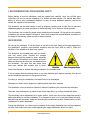
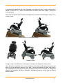
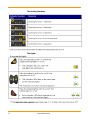
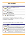
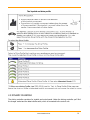
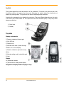
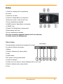
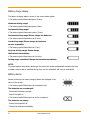
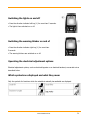
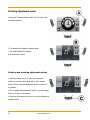
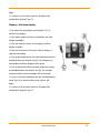
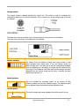
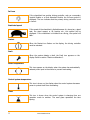
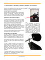
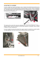
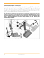
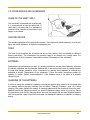
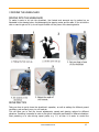
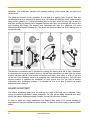
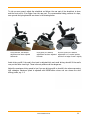
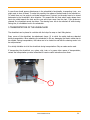
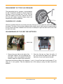
OWNER’S MANUAL
Read the manual carefully.
In matters that are unclear, we request that you contact us
Chasswheel Oy
Myllyharjuntie 6
71800 SIILINJÄRVI
Tel. +358 207 559 220
Fax: +358 207 559 221
Valued FOUR X URBAN user,
We would like to welcome You on becoming a user of the FOUR X URBAN. We thank You for Your
trust and we are sure that Your new wheelchair will meet Your expectations. When designing and
producing FOUR X URBAN, our main goal is to give every person an opportunity to move and
improve their quality of life. Your FOUR X URBAN electric wheelchair guarantees a smooth drive for
You on town streets as well as off-road. You do not have to plan Your routes, considering where You
can access with a wheelchair and where You cannot, as You can move wherever You like. FOUR X
Urban overcomes successfully all slopes and is able to easily climb over curbs. Snow, mud, roots of
trees are no longer an obstacle on Your journey.
By following our user manual, You will learn to use Your FOUR X URBAN electric wheelchair safely
and it will become a long-term technical aid for You.
We wish You a pleasant mobility experience with FOUR X URBAN.
www.chasswheel.com
2
WARRANTY
Chasswheel Oy offers a two- (2) year warranty for CHASSWHEEL FOUR X URBAN's casing, the base
of the electric wheelchair, its riding and steering devices, seat and motors. The warranty does not
cover batteries and charging devices. The frame of every wheelchair has a data label with an
individual serial number.
The warranty covers defects derived from the regular usage of the wheelchair. This warranty does
not cover general wear and tear or the damages derived from the misusage of the wheelchair or
inproper maintenance.
The warranty does not cover the results of the damages derived from overweight or incorrect
programming. General wear and tear appears e.g. on wheels, rubber, plate springs, swivel joints and
sliding surfaces. General wear and tear can also be considered to be louder motor noise. The
warranty does not cover indirect damage caused by any other damages.
3
www.chasswheel.com
DECLARATION OF CONFORMITY
The manufacturer:
Chasswheel Oy
Myllyharjuntie 6
71800 SIILINJÄRVI
Finland
Declares that the CHASSWHEEL FOUR X URBAN is class B electrically powered wheelchair
conforms to the following standard requirements
EN 12184: 2006
EN 1041: 1998
EN ISO 14971: 2007
EN12182: 1999
ISO 1999: 1997
ISO 6440: 1985
ISO 7176-1: 1999
-2: 2001
-3: 2001
-4: 1997
-5: 1986
-6: 2001
-7: 1998
-8: 1998
-9: 2001
-10: 1998
-11: 1992
-14: 1997
-15: 1996
Risto Heikkinen
Managing Director
www.chasswheel.com
4
CONTENTS
1 RECOMMENDATIONS FOR ENSURING SAFETY .......................................................................... 7
SAFE DRIVING .......................................................................................................................... 7
SAFE USAGE AND MAINTENANCE ............................................................................................... 9
PERMANENT LABELLING OF THE WHEELCHAIR ......................................................................... 10
2 EQUIPMENT AND ITS USAGE ................................................................................................. 12
2.1 USAGE OF THE STEERING DEVICE ...................................................................................... 12
2.2 DYNAMIC DX-REM420 ........................................................................................................ 13
2.3 DYNAMIC DX-REM550 ........................................................................................................ 18
Joystick .................................................................................................................................. 19
Status display .......................................................................................................................... 20
Battery charge display.............................................................................................................. 21
Battery alarms ......................................................................................................................... 21
System status ......................................................................................................................... 22
Using Buddy Buttons with the remote........................................................................................ 22
Steering the wheelchair with the remote.................................................................................... 23
Switching the wheelchair off .............................................................................................. 23
Locking/unlocking the wheelchair ...................................................................................... 23
Locking the wheelchair........................................................................................................ 23
Unlocking the wheelchair .................................................................................................... 23
Switching the lights on and off ........................................................................................... 24
Switching the warning blinker on and of ............................................................................ 24
Operating the electrical adjustment options ...................................................................... 24
Which symbols are displayed and what they mean ........................................................... 24
Entering adjustment mode .................................................................................................. 25
Selecting and actuating adjustment options ...................................................................... 25
Changing from setting mode to drive mode ....................................................................... 26
Further adjustment options ................................................................................................ 26
Deactivating programming mode ....................................................................................... 26
Changing the screen brightness.......................................................................................... 27
Setting the time ................................................................................................................... 27
Display / hide time display .................................................................................................. 28
Changing the screen backround.......................................................................................... 29
Error diagnosis ..................................................................................................................... 29
Error codes and diagnosis codes ......................................................................................... 30
2.4 R-NET JSM ........................................................................................................................ 32
2.2 ADJUSTMENT OF BACKREST, HEADREST, ARMREST AND FOOTREST .................................... 37
ADJUSTMENT OF BACKREST .................................................................................................... 37
MANUALLY ADJUSTED BACKREST ............................................................................................. 37
ELECTRICALLY ADJUSTED BACKREST ....................................................................................... 37
ADJUSTMENT OF HEADREST .................................................................................................... 37
ADJUSTMENT OF ARMREST...................................................................................................... 38
MANUAL ADJUSTMENT OF FOOTREST ...................................................................................... 39
2.3 OTHER DEVICES AND ACCESSORIES ................................................................................... 40
USAGE OF THE SAFETY BELT ................................................................................................... 40
LIGHTING DEVICE ................................................................................................................... 40
TIRES ..................................................................................................................................... 40
5
www.chasswheel.com
BATTERIES ............................................................................................................................. 40
CHARGING OF THE BATTERIES ................................................................................................ 40
FUSES .................................................................................................................................... 41
3 DRIVING THE WHEELCHAIR .................................................................................................. 42
MOVING INTO THE WHEELCHAIR ............................................................................................. 42
DRIVE PRACTICE ..................................................................................................................... 42
BALANCE ADJUSTMENT ........................................................................................................... 43
GOING UP STEPS .................................................................................................................... 45
4 FREEWHEELING ................................................................................................................... 45
5 TRANSPORTATION OF THE WHEELCHAIR .............................................................................. 46
6 MAINTENANCE OF THE WHEELCHAIR ..................................................................................... 47
DAILY CHECKS ........................................................................................................................ 47
WEEKLY CHECKS ..................................................................................................................... 47
CLEANING OF THE WHEELCHAIR.............................................................................................. 47
MEASUREMENT OF TYRE’S AIR PRESSURE ................................................................................ 48
CHANGING OF A WHEEL .......................................................................................................... 48
DISASSEMBLING OF THE SEAT AND BATTERIES ........................................................................ 48
INSTALLATION OF BATTERIES ................................................................................................. 49
PROGRAMMING ....................................................................................................................... 50
CHANGING THE LIGHT BULBS .................................................................................................. 50
ELECTRICAL DISTURBANCES IN THE WHEELCHAIR’S WORK....................................................... 50
7 STORAGE OF THE WHEELCHAIR ............................................................................................ 51
8 TECHNICAL DATA OF FOUR X URBAN .................................................................................... 52
www.chasswheel.com
6
1 RECOMMENDATIONS FOR ENSURING SAFETY
Before starting to use the wheelchair, read this manual very carefully. Here You will find good
instructions on how to use the wheelchair in a flexible and safe manner. The manual also offers
advice on how to act in problematic situations. In case of having additional questions, feel free to
contact the supplier of the wheelchair.
The wheelchair can be used indoors as well as outdoors, meaning that it helps You to overcome
obstacles appearing in normal conditions as well as allowing You to move on uneven grounds.
The wheelchair can be used by people whose weight does not exceed 125 kg and who are capable
of attaining the correct usage of the device. Users must possess the physical abilities necessary for
the usage of the steering system as well as steering devices.
SAFE DRIVING
Do not use the wheelchair if You feel that it is not safe to be used. Safety of its usage depends on
the wheelchair’s condition, environmental conditions and the user’s skills to drive it. Check the
condition of the wheelchair at least once a week.
The wheelchair has movable parts such as wheels,
rods and swivel joints. Consider the possible
dangers that might be caused by them, especially
when using the wheelchair near children and pets.
Make sure that they are kept at a safe distance from
the wheelchair. The parts that may cause harm
have been marked with symbols next to them.
Avoid loose clothing or objects that may get caught in the movable parts.
If You are aware that the steering device or any other essential part requires repairing, then do not
use the wheelchair and take it to be repaired at once.
If pushing or towing the wheelchair, the brakes have to be disengaged.
Movement on slopes can be dangerous if parking brakes have been released.
The wheelchair is four-wheel drive. Practise is required for attaining the correct driving technique.
Take care when manoeuvring in places where wheels may slide, e.g. a slope covered with grass.
The wheelchair has an adjustment tilt in space system which upon the correct usage improves the
safety and ability to overcome obstacles. It is essential to learn how to use that system correctly.
Before driving the wheelchair, make sure that the seat is positioned correctly. Please see the section
„Adjustment of weight distribution“.
Driving the wheelchair on a slope may be unstable if the weight distribution has not been adjusted
correctly. One needs to be extra careful adjusting the weight distribution whilst on a slope.
7
www.chasswheel.com
The wheelchair’s capability to get up a hill depends on the degree of slope. It may be dangerous to
exceed an incline of 20° or driving on surfaces that are uneven, more than 150mm (look at the
drawings below).
Always use low speed and avoid making forceful steering movements when driving on a slope or on
uneven ground.
Driving positions for uphill and downhill.
Obstacle 150mm
Driving in water is prohibited due to the danger of damaging the wheelchair’s electric parts.
When driving the wheelchair in dim or dark conditions, driving lights should always be used as they
allow You to see obstacles or dangers in Your path. It is also very important for other road users to
see You.Releasing the steering lever (Joystick) will stop movement of the wheelchair. In a dangerous
situation, the wheelchair can also be stopped by unplugging its electric current from the steering
device (Joystick).
www.chasswheel.com
8
Before using and during usage, check the batteries’ charge. Always charge the batteries if they are
empty or low. The standard charging device of the wheelchair does not allow the batteries to be
overcharged.
The functionality of the wheelchair can be disturbed by electromagnetic fields which can be caused
by e.g. mobile phones and other similar devices. The wheelchair itself can disturb other
electromagnetic devices from functioning, such as shops’ security systems.
Do not leave the wheelchair exposed to direct sunlight. The wheelchair’s metal parts and surfaces,
such as the seat and arm-rests, overheat easily. Also avoid leaving the wheelchair out in cold
weather or frost.
If You have used the wheelchair in damp conditions, be sure to take care of drying it, e.g. putting it
into a warm room. Do not leave the wheelchair outside or in a cold/damp room. Failing to follow the
beforementioned advice can cause damage to the wheelchair.
SAFE USAGE AND MAINTENANCE
Factory programmed parameters have been installed into the wheelchair’s control system and they
are suitable for most users. Some of these parameters can be changed. Programming can only be
carried out by an autherised specialist who has knowledge of the wheel chairs control systems.
Wrong programming can be hazardous and damage the control systems.
The wheelchair’s control system should be exposed to extreme conditions as little as possible.
Damage to the wheelchair’s cables causes a safety issue that should be immediatley reported to an
autherised technician.
Check the condition of the tyres on regular basis. It is essential for steering as well as for durability
of the wheels to have correct tyre pressure. The measurement of tyre pressure has been described
in the section „Maintenance of the wheelchair“.
To avoid the usage of the wheelchair without permission, use the locking key (blue). It is hazardous
if the wheelchair is used by an unauthorized person.
For transportation, always attach the wheelchair to the body of the car. It is strictly prohibited to sit
in the wheelchair whilst being transported.
Repair and alteration works are prohibited without supplier’s authorization.
The allowed maintenance works that can be carried out by the user are described in section
“Maintenance of the wheelchair.“
If the wheelchair is being maintained or adjusted, then the control system must be switched off.
Only gel batteries can be used in order to avoid the risk of electrical damage.
If electric tools are used near the batteries, then one has to consider the possibility of a short-circuit.
Usage of open fire is prohibited due to a danger of explosion. Battery box is not meant to be used
for storage of other objects. The wires to the batteries are not to be disconnected by oneself. In
case of problems, please contact an autherised technician.
9
www.chasswheel.com
PERMANENT LABELLING OF THE WHEELCHAIR
Identification plates can be found on the left side of the frame.
Data of the wheelchair’s classification.
Maximum incline is 20 degrees
Maximum angle is 150 mm
Located on the casing’s cover in the rear part.
Instruction for connecting batteries
Located on the inside of the casing’s cover.
80A
The size of the main circuit breaker
Located in the battery box, on the cover of the fuse holder.
Using other than gel batteries is forbidden –warning.
Located on the cover of the protection box.
www.chasswheel.com
10
The symbol of brake’s release
D = brakes are locked, one can ride the wheelchair
N = brakes are released, the wheelchair can be towed
Located on both shafts on the side of the brake’s
protection box
NB! Read the label, located on the right and left side of
the lifting frame
Located on the side of the seat frame
Risk of finger trapping
Located on the right and left side of the lifting frame
Do not push the wheelchair from the back rest
11
www.chasswheel.com
2 EQUIPMENT AND ITS USAGE
2.1 USAGE OF THE STEERING DEVICE
The steering device consists of a steering lever (Joystick) and panel. Underneath the steering lever
is the charging device’s interface and data transmitting cable which is connected to the steering
center underneath the seat. The wheelchair is available with three different kind of steering system
modules: Dynamic DX-REM420 or DX-REM550 and R-NET JSM.
Steering lever or Joystick
The speed and direction of the wheelchair is adjusted by the steering lever (Joystick). The further
the lever is pushed forward, the faster the wheelchair moves. Releasing the steering lever will stop
the wheelchair and will connect the parking brakes. The steering lever can be used also for
adjusting many additional actions. The standard buttons for the steering lever are suitable for most
users. However, one can also have other options or have a button made by special order. Do not
replace the button with self-contructed details as this may cause a dangerous situation.
www.chasswheel.com
12
2.2 DYNAMIC DX-REM420
Steering panel DX-REM420
Buttons and screen are located on the steering panel. The
function of buttons are described in more detail in this chapter.
If the steering device has been switched on, the lights will
appear on the screen and the screen will display a function to
show that it has been switched on. The symbols displayed on
the screen are described in more detail below.
ON/OFF – switch
13
www.chasswheel.com
www.chasswheel.com
14
The Seating Functions
The Lights
15
www.chasswheel.com
Battery charge indication
Other indications
www.chasswheel.com
16
Battery Charging
System Lock
17
www.chasswheel.com
The Joystick and drive profile
2.3 DYNAMIC DX-REM550
The driving controller consists of a joystick and control panel. Under the driving controller you'll find
the charger socket and the data transfer cable, which is connected to the control unit.
www.chasswheel.com
18
Joystick
The joystick adjusts the speed and direction of the wheelchair. The further you push the stick from
the central position, the greater the drive speed. Releasing the joystick stops the wheelchair and
applies the parking brakes. The joystick is also used for adjusting extra operations.
Joystick with a standard knob is suitable for most users. There are different alternatives to this knob
or the knob can be tailor-made. Do not replace the knob with self-made parts, as they may cause
dangerous situations.
1) Drive lever
2) Display
Top side
Display and controls
3) Direction indicators left and right
4) ON / OFF key
5) Function key
6) Activate drive mode / switch-through
numbers 1 to 5 in the display
7) Direction indicators right and warning
blinker
8) Activate setting mode / switch-through
9) Horn
Display
10) Status bar indicator
11) Drive mode or setting mode display
Assigment of display fields in display to keys
19
www.chasswheel.com
Bottom
1) Socket for charging and for programming
the remote
2) Socket for bus cable
3) Socket I for Buddy Button (corresponds to
“Activate drive mode / switch-through” key).
This key is deactivated as standard.
4) ON/OFF socket for Buddy Button (corresponds
to ”ON/OFF” key)
5) Socket II for Buddy Button (corresponds to
”Activate setting mode” key).
This key is deactivated as standard.
The cover cap must be removed if sockets 2 to 5 are to be used.
To do this, remove the Phillips screw.
Status display
The status display is located at the top edge of the screen.
Status display
It contains the following information:
1) Battery
2) Direction indicators left, warning blinker
3) Light
4) System status
If the system is working without faults,
no symbol is displayed
If a fault occurs, the ”spanner” symbol is displayed with an error code.
5) Direction indicators right, warning blinker
6) Time
www.chasswheel.com
20
Battery charge display
The battery charging status is shown in the screen status display
• The battery symbol illuminates green (5 bars):
Maximum driving range!
• The battery symbol illuminates green(4 bars):
Decreased driving range!
• The battery symbol illuminates yellow (3 bars):
Decreased driving range! Please charge the batteries.
• The battery symbol illuminates red (2 bars):
Low driving range! Please charge the batteries
as soon as possible
• The battery symbol illuminates red (1 bar):
Very low driving range! Please charge
the batteries immediately.
• The battery symbol illuminates red (no bars):
Driving range exhausted! Charge the batteries immediately.
NOTE!
To protect against total battery discharge, the electronics system automatically switches the drive
to battery reserve after a specified driving time, and the wheelchair will come to a standstill.
Battery alarms
Alarms concerning the battery charging status are displayed in the
centre of the screen.
• The battery symbol illuminates red (completely full):
The batteries are overcharged!
- Disconnect the battery charger.
- Switch the lights on.
• The battery symbol illuminates red and is crossed out:
The batteries are empty!
- Switch the wheelchair off.
- Charge the batteries immediately.
21
www.chasswheel.com
System status
The system status is shown in the middle of the status display if a
fault occurs.
An error code is displayed to the right of the "spanner" symbol. You
can use this error code to help find the cause of the fault as
described in Chapter 2.10
Using Buddy Buttons with the remote
A Buddy Button (4) is an additional button which can be used to activate remote functions. The
sockets for Buddy Buttons are located underneath the remote.
1) Socket I
(corresponds to "Activate drive mode/switch-through"
key)
The button is deactivated as standard.
2) ON/OFF socket
(corresponds to "ON/OFF" key)
3) Socket II
(corresponds to "Activate setting mode" key)
The button is deactivated as standard.
4) Buddy Button
The cover cap must be removed if sockets
1 to 3 are to be used.
To do this, remove the Phillips screw.
www.chasswheel.com
22
Steering the wheelchair with the remote
• Press the "ON/OFF" key.
• The display illuminates.
• The mode display (A) shows the drive level.
• The wheelchair is ready to drive.
• You can set the drive levels using the drive mode key
(C). In this case, drive level 1 is the slowest and drive
level 5 the fastest setting.
• Within each drive level you can carry out fine settings
for the speed using the function key (B). The fine
settings are displayed in the ring (D).
This enables, for example, adapting the speed to that
of an attendant.
Switching the wheelchair off
• Press the ”ONN/OFF” key (1).
• The remote switches off.
Locking/unlocking the wheelchair
Locking the wheelchair
• Press the ”ON/OFF” key (1) for more than 4 seconds
• A lock shown in the display and the remote switches itself off.
Unlocking the wheelchair
• Press the ”ONN/OFF” key (1) .
• Press the horn (2) twice within 10 seconds.
• The display illuminates.
• The mode display (A) shows the drive level.
• The wheelchair is ready to drive.
23
www.chasswheel.com
Switching the lights on and off
• Press the direction indicator left key (1) for more than 5 seconds.
• The light is then switched on or off.
Switching the warning blinker on and of
• Press the direction indicator right key (1) for more than
5 seconds.
• The warning blinkers are switched on or off.
Operating the electrical adjustment options
Electrical adjustment options, such as electrical legrests or an electrical backrest, are carried out as
described below.
Which symbols are displayed and what they mean
Only the symbols for functions which the wheelchair actually has available are displayed.
www.chasswheel.com
24
Entering adjustment mode
• Press the "Activate setting mode" key (A) next to the
wheelchair symbol.
• The wheelchair changes to setting mode.
• The mode display (B) changes
to a wheelchair symbol.
Selecting and actuating adjustment options
• Press the function key (C) under the wheelchair
symbol or move the drive lever left or right several
times until the required adjustment option is shown in
the display.
• The corresponding adjustment option (e.g. seat tilting)
is shown in blue on the display.
• Press the drive lever to the front or rear to activate the
actuator motor.
25
www.chasswheel.com
NOTE:
The distance you press the drive lever determines the dynamics of the movement.
If you only press the drive lever a little, the actuator motor will only move slowly.
If you press the drive lever as far as you can, the actuator motor will move faster.
Changing from setting mode to drive mode
• Press the "Activate drive mode/switch-through" key (D).
• The remote will switch back to drive mode.
• The mode display (A) shows the drive level.
Further adjustment options
Deactivating programming mode
• Press the "Activate setting mode" key (A) next to the P
symbol.
• Press the function key (B) or move the drive lever right
or left until the required adjustment option is shown in
the display.
• Press the drive lever forward to confirm the required
adjustment option.
www.chasswheel.com
26
You can change the following settings.
Changing the screen brightness
• The symbol for screen brightness (see Chapter 2.9.1)
is shown in the display.
• Press the function key (B) or move the drive lever right
or left to change the screen brightness.
• The bar underneath the sun symbol shows the
adjusted value.
• Press the "Activate setting mode" key (A) or move the
drive lever right or left to confirm the required setting
options.
• To carry out further settings, press the "Activate setting
mode" key (A) or move the drive lever right or left
again.
• To return to drive mode, press the "Activate drive
mode/switch-through" key (C).
Setting the time
• The symbol for time (see Chapter 2.9.1) is shown in
the display.
• Press the function key (B) or move the drive lever right
or left to select the individual digits in the time display.
• The digit to be changed is shown blinking.
• Move the drive lever forwards to change the individual
digits in the time display.
• Move the drive lever to the rear to save the changed
time.
• To carry out further settings, press the "Activate setting
mode" key (A) or move the drive lever right or left
27
www.chasswheel.com
again.
• To return to drive mode, press the "Activate drive
mode/switch-through" key (C).
Display / hide time display
• The symbol for time display (see Chapter 2.9.1) is
shown in the display.
• If the green symbol is shown in the display, the time
display is available.
• If the red symbol is shown in the display, the time
display is hidden.
• Press the drive lever to the right or left to display or
hide the time display.
• If you press the drive lever forwards when two ticks are
displayed above the function key (B), the changes you
have made to the time display will be saved.
• If you press the drive lever forwards when two crosses
are displayed above the function key (B), the changes
you have made to the time display will not be saved.
• To carry out further settings, press the "Activate setting
mode" key (A) or move the drive lever right or left
again.
• To return to drive mode, press the "Activate drive
mode/switch-through" key (C).
www.chasswheel.com
28
Changing the screen backround
• The symbol for screen background (see Chapter 2.9.1) is
shown in the display.
• Press the function key (B) or move the drive lever right or left
to select one of the three modes.
• Select (1) if you want to have a black screen background.
• Select (2) if you want to have a white screen background.
• Select (3) if you want the screen background to be set to
standard.
• Press the "Activate setting mode" key (A) or move the drive
lever forwards to save the change.
• To carry out further settings, press the "Activate setting
mode" key (A) or move the drive lever right or left again.
• To return to drive mode, press the "Activate drive
mode/switch-through" key (C).
NOTE
The Automatic screen background setting is standard on delivery. When the lighting is switched
on, the background will change from white to black.
Error diagnosis
If the electronic system shows a fault, please use the following fault-finding guide to locate the
fault.
NOTE
Ensure that the drive electronics system is switched on before starting any diagnosis.
29
www.chasswheel.com
Error codes and diagnosis codes
The drive electronics system is able to correct some errors automatically. In this case, the code
number in the status display will disappear. To do this switch the remote on and off several times.
Wait approx. 5 seconds each time before switching the remote on again. If the error is not
corrected by this process, localise the error using the code numbers listed below.
www.chasswheel.com
30
In the event of any electrical fault caused by electromagnetic emissions, turn the wheelchair/aid off,
remove the wheelchair/aid from the effecting area by placing brake lever arms in neutral position.
Then wait 5 minutes and turn the wheelchair/aids power back on. If the aid has been effected in any
way contact immediately your local Chasswheel specialist.
31
www.chasswheel.com
2.4 R-NET JSM
Control panel
The control panel contains push buttons and an LCD display.
Operation of the push buttons is defined later in this chapter. When
the driving controller unit is switched on, the LCD display is
illuminated in the background and an icon of the currently used
function is displayed. The symbols displayed are defined later in
this chapter.
ON/OFF- button
With the ON/OFF button, the driving controller can be switched on and off. Do
not use this switch to stop the wheelchair, except in an emergency.
Horn button
A sound signal sounds when the push button is pressed.
Speed buttons, Decrease/Increase
The maximum speed of the wheelchair can be increased by pressing the right
push button and decreased by using the left push button. The choice of
www.chasswheel.com
32
maximum speed is seen on the display whilst choosing, provided it is
programmed to be displayed. The maximum speed is the lowest when there is
only one darkened column on the display and the greatest when all the
columns on the display are darkened. When the joystick is moved forwards or
backwards, the driving controller transfers to driving mode and applies the
selected maximum speed. The maximum speed can also be adjusted while
driving.
MODE button
With the MODE button you can navigate the adjustment menu. The available
menus depend on the programming and the available operations of connected
optional equipment.
Profile button
The desired user profile can be chosen with the profile button. The available
profiles depend on the driving controller’s programming and its equipment. The
driving controller has pre-programmed profiles for indoor and outdoor driving.
The maximum speed for the indoor driving profile has been adjusted lower
than the speed in the outdoor driving profile.
Left turn indicator switch
By pushing the button, the wheelchair's left turn indicator lights are switched
on. The indicator lights are switched off by pressing the push button again.
When the indicator lights are on, the LED next to the push button will flash.
Right turn indicator switch
By pushing the button, the wheelchairs right turn indicator lights are switched
on. The indicator lights are switched off by pressing the push button again.
When the indicator lights are on, the LED next to the push button will flash.
Hazard warning switch
By pressing this push button, all the wheelchair’s indicators will switch on.
Pressing the push button again will switch the indicators off. When the
warning indicators are on, the LEDs next to the push buttons for warning and
direction indicators will flash.
Lights switch
The drive lights are switched on and off. When the drive lights are switched
on, the LED next to the push button will illuminate.
33
www.chasswheel.com
Charger socket
The charger socket is situated beneath the control unit. The socket is used for recharging the
wheelchair’s batteries or to lock the wheelchair. Only connecting the proper charger plug or lock key
is permitted.
LCD DISPLAY
The state of the driving controller can be observed using the icons shown on the display.
The icons shown and used on the display are the following.
Battery indicator
The picture shows the battery’s charge level. High number of dark
pillars indicates good charge level. If the icon flashes slowly, the
battery charge level is low and they should be recharged immediately.
When the batteries are recharging, the pillars will be darkened from
left to right. The wheelchair cannot be used until the charger has been
detached from the charger socket and the drive –controller has been
switched off and back on.
Speed indicator
This icon indicates the maximum speed. As the number of dark
columns increases, so does the maximum speed. The maximum speed
can be adjusted using the maximum speed adjusting switch.
Current profile
The profile number and name indicates the profile currently in use.
www.chasswheel.com
34
In Focus
If the wheelchair has another driving controller. such as a secondary
Joystick Module or a Dual Attendant Module, the InFocus symbol is
displayed. The icon indicates that the primary driving controller is not
in control.
Restricted speed
If the speed of the wheelchair is limited because of a sharp turn, raised
seat, the stand support or lift function etc., this symbol will be
displayed. If the wheelchair is inhibited from driving, the symbol will
flash.
Restart
When the Restart icon flashes on the display, the driving controller
must be restarted.
Fault
When the system detects a fault, the Fault icon appears on the
display. Refer to section “Electric malfunctions”.
Motor temperature
This icon appears on the display when the system has automatically
reduced power input to the motors to prevent overheating.
Control system temperature
This icon is shown on the display when the control system decreases
power to protect itself from overheating.
Timer
This icon is shown when the control system is changing from one
operation mode to another. The sand glass represents the time
lapsing.
35
www.chasswheel.com
Balance and seat adjustment
The wheelchair’s balance and seat can be adjusted by pressing the
MODE button, whereupon this icon will be seen on the display.
The seat part that is highlighted in the icon is currently adjustable.
Adjustment is carried out by moving the joystick forwards and
backwards. Different parts of the seat are chosen by moving the
joystick to the left and right.
Temporarily displayed icons
In so far as the temporary icons are programmed to be seen, the icons below will be temporarily
displayed by pressing the Speed or Profile buttons.
Locking
The Wheelchair can be locked using the locking key. To lock the
wheelchair the driving controller has to be switched on. The locking
key is inserted into the charger socket and immediately pulled out.
The wheelchair is now locked and the display clearly shows a lock
icon.
To unlock, first switch the current on. Driving is however still not possible. Insert the locking key into
the charger socket and immediately pull out. It is now possible to drive the wheelchair.
Troubleshooting
If the control system detects an error, a flashing exclamation mark (!) appears on the display
together with a notice with the code of the possible fault. Refer to section “electric malfunctions”.
www.chasswheel.com
36
2.2 ADJUSTMENT OF BACKREST, HEADREST, ARMREST AND FOOTREST
Be careful when adjusting as there may be a danger of crushing. For the best adjustment, use the
assistance of a helper or maintenance company.
ADJUSTMENT OF BACKREST
The back-rest of the wheelchair can be adjusted either
manually or electrically. If adjusting the backrest
forwards, then pay attention that nothing would get
stuck in between the armrests and the seat’s padding.
MANUALLY ADJUSTED BACKREST
To adjust the backrest manually, pull the lever located
at the side of the backrest, at the same time sliding
the backrest or turning the wheel on the side of the
back, until the backrest is in the desired position.
ELECTRICALLY ADJUSTED BACKREST
Back-rest is adjusted electrically through the steering
device. For choosing the adjustment mode, press on
the SUPPLEMENTARY DEVICE-button until the screen
displays the lights indicating the seat’s settings.
Then the correct seat settings can be chosen by moving
the steering lever either to the left or right.
ADJUSTMENT OF HEADREST
In order to adjust the height of the headrest, the
plastic butterfly nut (1) at the back of the headrest
needs to be loosened until the headrest can move
freely on its attachment. Once the desired height has
been achieved, the butterfly nut has to be tightened
up again. The height of the headrest can be adjusted
smoothly.
In order to adjust the depth of the headrest, the
plastic butterfly nut (2) behind the rod needs to be
loosened until the headrest can move freely on its
attachment. Once the desired position has been
achieved, the butterfly nut has to be tightened up
again. The depth of the headrest can be adjusted
smoothly.
The padding of the headrest is attached to the rod by
a globe joint (3). The padding can be easily changed
according to the user's head position.
37
www.chasswheel.com
NB!
If the adjustment of backrest is
incorrect, then pay attention to the
position of the seat and adjustment of
the weight distribution. If after
adjustment, the backrest stays too far
forward or too far backwards, then
weight distribution could have been
adjusted to the wrong place and the
wheelchair may fall over. Contact an
authorized maintenance company.
ADJUSTMENT OF ARMREST
In order to adjust the armrest's side distance, screw 1 needs to be loosened and armrest has to be
moved to the side. Once the desired position has been achieved, the screw needs to be tightened
up. The maximum possible armrest's side distance is 60 mm (drawing below). In order to adjust the
armrest's bottom angle, screw 2 needs to be loosened. Once the desired position has been achieved,
the screws need to be tightened up.
The height and the angle of the armrest are adjusted with a 5 mm hex key (Allen key). In order to
adjust the height, screw (A) is loosened and moved either upwards or downwards. Once the height
is suitable, the screw is tightened up.
In order to adjust the angle of the armrest, the support needs to be moved into a vertical position.
For angle adjustment, screw (B) is turned until the desired position has been achieved.
www.chasswheel.com
38
MANUAL ADJUSTMENT OF FOOTREST
In order to adjust the distance between footrest and seat, the hex screws (1) in the front part of the
seat need to be loosened. Once the correct distance has been gained, the screws are tightened up.
The height is adjusted with a 5 mm hex key (2). The angle of the foot base (3) is adjusted with a 13
mm spanner. In order to adjust the corner of the footrest, the lever (4) needs to be raised after
which the lock is released and the position can be adjusted. Once the correct position has been
gained, the lever is released. Footrest is locked into the chosen position.
NB! When driving uphill, overcoming obstacles or adjusting the weight distribution, the
position of the footrest needs to be taken into consideration! When adjusting the weight
distribution, firstly, one has to make sure that the footrest would not smash into the
cover or tires of the wheelchair. If footrest keeps smashing into the obstacles, the
footrest can get damaged.
39
www.chasswheel.com
2.3 OTHER DEVICES AND ACCESSORIES
USAGE OF THE SAFETY BELT
The wheelchair is equipped with a safety belt.
It is recommended to use the safety belt. If
safety belt is not used, then it is important to
make sure that it would not hang down or get
caught in the wheels.
LIGHTING DEVICE
The standard equipment of the wheelchair includes 2 front lights with inbuilt indicators, two red rear
lights with inbuilt indicators. All lights are maintenance-free.
TIRES
The tires of the wheelchair are all similar and due to their pattern, they are suitable for different
flooring and terrain. The wheelchair's tire pressure needs to be checked on a regular basis. The
measurement of the tire pressure is described in section “Maintenance of the wheelchair”.
BATTERIES
Maintenance-free gel batteries are used. It is strictly prohibited to use any other batteries, otherwise
the electric equipment can be damaged. Batteries are in the casing's box which is located between
the seat and casing's protective cover. Instructions for removal and installation of batteries are
described in section “Maintenance of the wheelchair”. Follow the safety instructions applied for
batteries in section “Safety recommendations”. Used batteries have to be taken to a suitable
collection point.
CHARGING OF THE BATTERIES
In order to charge the wheelchair's batteries, the charging devices plug needs to be connected with
the steering device's charging interface (look at section “Charging interface”, page 14). During
charging, the screen displays the symbol of charging batteries and the wheelchair cannot be used.
Batteries need to be charged at once if the symbol of batteries charge shows only one bar. Follow
the instructions given for the charging device. Use only the charger that has been supplied together
with the wheelchair. Usage of an incorrect charger can damage the batteries, wheelchair or charging
device.
www.chasswheel.com
40
FUSES
The wheelchair's release point (80A) is installed between the batteries. If the fuse has blown, the
wheelchair's electric function will not work. This fuse cannot be changed by the wheelchair's user
himself, but must be done by an authorized specialist.
41
www.chasswheel.com
3 DRIVING THE WHEELCHAIR
MOVING INTO THE WHEELCHAIR
To make it easier to sit into the wheelchair, the footrest and armrests can be pushed up as
illustrated in the drawing below. Avoid damaging the steering center and its cable. If you sit into the
chair or want to get out of it, do not forget to switch off the power of the steering device.
DRIVE PRACTICE
Take your time to get to know the wheelchair's operation, as well as settings for different ground
conditions, such as sand, snow, ice, off road etc.
This will allow you to find the correct adjustments, speeds and steering options for different
situations. Practicing is essential in order to be able to ride safely and flexibly in different situations.
Start practicing on a slow driving speed profile, e.g. 1-3, as then it is easier to control the
www.chasswheel.com
42
wheelchair. The wheel-chair functions with powered steering, which means that one has to be
careful at first.
The speed and direction of the wheelchair is controlled by a steering lever (Joystick). Take into
consideration that when releasing the steering lever, the wheels will straighten into a central forward
facing position (drawing 1). Turning the steering lever to the right, wheels will turn right (drawing 2)
and when pushing the steering lever diagonally forwards and right, the wheelchair will move to the
right (drawing 3a). Pulling the steering lever backwards and right, the wheelchair will move
backwards and to the right (drawing 3b). The wheels will move the same way if the steering lever is
turned to the left.
The direction of movement can be corrected by pushing the steering lever left or right. Afterwards,
the steering lever is pushed forwards and only minimal side movements are made until the correct
direction has been gained. Avoid forceful movements and firstly, drive slowly in order to gain the
correct feel. If the wheelchair moves in an undesired way, release the steering lever. Once you have
acquired practice of operating the wheelchair on even ground, then You can start to practice
overcoming more challenging surfaces, it is essential for You to be able to adjust the weight
distribution before doing so.
BALANCE ADJUSTMENT
The balance adjustment means that the seat and the angle of the seat can be adjusted. When
moving the balance adjustment system backwards, the seat will be sliding backwards and when
moving the balance adjustment system forwards, the seat will be moving forwards.
In order to adjust the weight distribution, the steering lever needs to be moved forwards or
backwards until one has reached the chosen setting. To return to the drive mode, press the MODEbutton.
43
www.chasswheel.com
To ride on even ground, adjust the wheelchair as follows: the rear part of the wheelchair is down
and the front part is 5 cm higher from the rare part. The recommended riding positions for slope,
even ground and going downhill are shown in the drawing below.
Going downhill, the balance
adjustment has been adjusted
backwards
Going uphill, the balance
adjustment has been adjusted
forwards
On even ground, the balance
adjustment is in a central position
and the front edge of seat is slightly
risen up
Avoid driving uphill if the seat's front part is adjusted high and avoid driving downhill if the seat's
rear part has been risen high. These incorrect positions can be dangerous.
Adjust the maximum driving speed to low if you are driving uphill or downhill, also when overcoming
high obstacles. Maximum speed is adjusted with MODE-button where one can choose the slow
driving profile, e.g. 1-3.
www.chasswheel.com
44
GOING UP STEPS
Approach the step from the side, so that the wheels can get on the step together at once (1). Bring
balance adjustment backwards and pull the footrest up so that it would not smash into the surface /
back of the step. Get the wheelchair's front wheels on the step (2).
1
2
Bring balance adjustment forwards, so that the rear part of the wheelchair would be lighter and you
could get the whole wheelchair onto the step (3). Eventually get the balance adjustment into even
ground driving mode. This driving style can be used, in order to overcome bigger obstacles (4).
3
4
4
FREEWHEELING
45
www.chasswheel.com
In case there should appear disturbances in the wheelchair's functionality, transporting it etc., one
might want to have it towed. To make this possible, the release of brakes needs to be switched on.
To switch them on, the engine's red brake release levers (2 pieces) on the axles have to be turned
backwards to the wheelchair's drive direction. This means that the front axle's brake release lever
has to be pulled towards the chair and the rear axle’s lever away from the chair. If the brakes are
released, the wheelchair cannot be driven. The steering lever has to be switched off while towing.
During tow, it is forbidden to sit in the wheelchair.
5 TRANSPORTATION OF THE WHEELCHAIR
The wheelchair can be placed in a vehicle with the help of a ramp or chair lifting device.
Every corner of the wheelchair has attachment hoops (1) to which the safety belts are attached
during transportation. When attaching the wheelchair in the car, damaging the electric cables has to
be avoided. During transportation, the brakes are to be locked on and that the steering center is to
be well-protected.
It is strictly forbidden to sit in the wheelchair during transportation. Only car seats can be used.
If transporting the wheelchair on a plane, ship, train or by some other means of transportation,
contact the transportation provider beforehand to receive useful instructions from them.
1
www.chasswheel.com
46
6 MAINTENANCE OF THE WHEELCHAIR
If you have used the wheelchair in damp conditions, make sure that the wheelchair is dried properly
by putting it in a warm and dry room. Do not leave the wheelchair outside or in a cold/damp room.
Ignoring the before mentioned instructions can cause damage to the wheelchair.
If taking regular care of the wheelchair, it is secured that your wheelchair is in a good working
condition and safe. A well-maintained wheelchair is a long-term aid. Some of the maintenance can
be carried out by the user himself, but more complicated maintenance methods have to be carried
out by an authorized maintenance company. The wheelchair needs to have an annual technical
checkup in a maintenance company authorized by the supplier. Supplier is not responsible for the
mistakes that have occurred due to the wheelchair not being maintained at all or maintained
incorrectly.
DAILY CHECKS
Before riding the wheelchair, check visually its general condition. If the steering device has been
switched off, make sure that the steering lever is not bent or damaged and moves to the central
position once it is released. Check that all interfaces are in place and undamaged, also check the
condition of the cables. Make sure that the thin rubber band around the steering lever is not
damaged. This rubber band has to be handled carefully. Make sure that the steering center is
attached to the wheelchair. Do not fasten up the screws too tightly.
WEEKLY CHECKS
Testing of brakes can be carried out on an even ground where there is at least one meter of empty
space around the wheelchair. Switch the steering device on. Make sure that the light turns on or
starts flashing within a second. Push the steering lever slowly forwards until you hear that the
parking brakes are functioning. The wheelchair can start moving. Release the steering lever at once,
after which within a few seconds you can hear the sound caused by the brakes starting to function.
Repeat this test three times, also pushing the steering lever backwards, to the left and right.
Check that the lights, indicator lights and adjustment of weight distribution are functioning. If your
wheelchair's back-rest and/or foot-rest is electrically adjusted, then make sure to test out their
functionality as well.
If problems appear, the wheelchair should not be used and Maintenance Company needs to be
contacted.
CLEANING OF THE WHEELCHAIR
The wheelchair can be cleaned with a light diluted washing solution on a damp cloth. Avoid using
undiluted washing substances as they can damage the textile and plastic details. Follow the
instructions of the washing substances' suppliers for cleaning different materials. Steering center
needs to be cleaned immediately if dirt has got into it. It is forbidden to use a pressure wash or
water spray as the wheelchair's electric devices can get damaged as a result.
47
www.chasswheel.com
MEASUREMENT OF TYRE’S AIR PRESSURE
The appropriate tire’s air pressure is approximately
3.5 bar. It should be avoided for the air pressure to
fall below 1.3 bar or increase over 3.5 bar. This will
cause the wearing of the tires, reduces the hold of
the tires and causes excessive friction which will
decrease the carried out distance.
CHANGING OF A WHEEL
Wheel is connected with four hex screws, the size of the key is 4 mm. Open the screws and remove
the wheel. The sides of the wheel are attached with smaller screws which cannot be opened before
the air pressure has been released from the tire do not attempt to open the center bolt as this holds
the hub to the axle.
DISASSEMBLING OF THE SEAT AND BATTERIES
1. Remove the cover fabric in the back of the
seat frame. Cables 2 and 3 are attached into
the cable 1, which is connected to the Power
Module. Detach the lights’ white connectors.
2. Move the foot-rest up. Open the bolts, (4
pcs.) and remove the plastic cover. Open the
seat nuts, (4 pcs.) and remove the seat.
Disconnect the following cables of the batteries: (- and +) (A and B) and main circuit breaker (C), by
using an 11 mm spanner. Take the batteries out of the casing by using the belts around the
batteries.
www.chasswheel.com
48
INSTALLATION OF BATTERIES
-
-
Check that the rubber details in the bottom of the battery box are in place. Place the batteries in
the battery box (terminals towards the middle part of the chair) and put the padding between
the walls of the batteries and battery box.
Connect the black -(A) and red +(B) cable.
Place the main fuse (C).
Check that all connected parts are tightly together.
For prevention of eremacausis, a clip polish can be used.
Put the casing’s cover into place and put the seat’s frame
on top of the casing.
NB!
After placing the seat’s casing,
always make sure that the
locking taps are tightly locked
and in place before using the
chair again.
49
www.chasswheel.com
PROGRAMMING
Wheelchair’s driving settings can be changed through programming. When the wheelchair is handed
over to a user, its settings have been set so that they are suitable for most users. Through
programming can be changed e.g. the reaction time of the steering lever, the transitional time of the
electric flow going into save mode and the speed of the turning wheels. If you want to change the
wheelchair’s settings, then contact either the wheelchair’s supplier or manufacturer.
CHANGING THE LIGHT BULBS
The wheelchair’s light bulbs are maintenance-free. In case of a possible problem, the whole light has
to be changed.
Open screws located behind the lamp
(In rear lights screws for rubber fasteners are
located below the covering.
In front lights screws are located on top of the
covering.)
DRIVING LAMP: Maintenance-free LED-lamp
REAR LAMP: Maintenance-free LED-lamp
DIRECTION-INDICATOR LAMP: Maintenancefree LED-lamp
ELECTRICAL DISTURBANCES IN THE WHEELCHAIR’S WORK
If the steering device notices a disturbance in the electric system, then a tool symbol starts flashing
For securing safety, the usage of the wheelchair during the disturbance is prevented. The most
common electric system disturbances are derived from interfaces or batteries. The reasons of the
most often occurring disturbances are described below.
Steering device has gone into an electric power saving mode. It happens automatically when the
steering device has not been used for a while. Time depends on the setting of the steering device.
For switching it on, the steering device needs to be switched off for once and then switched on
again.
The batteries have not been charged correctly if the symbol of the batteries’ charge starts flashing.
Batteries need to be charged on the first opportunity.
When charging batteries, check that the charging interface is not connected to the steering device.
www.chasswheel.com
50
It is possible that the interfaces of the steering system or battery have disconnected. Switch off the
steering device and check if all the interfaces are in the correct place.
The releases of the brakes have been switched on. Turn the release of the front axle’s brake away
from the wheelchair and the release of the rear axle’s brake towards the wheelchair. Instructions can
be found in section „Freewheeling“.
Turn the steering device on and try to move with the wheelchair. If a key symbol flashes on the
screen, then turn the steering device off. Do not use the wheelchair and contact the maintenance
company.
7 STORAGE OF THE WHEELCHAIR
Protect the wheelchair during storage from heat and dampness. The wheelchair can be stored in a
smaller room if the backrest, armrests, and footrest are folded together.
Disconnect the batteries and store them in a dry and cool place. During storage, the batteries need
to be charged at least once every half a year.
51
www.chasswheel.com
8 TECHNICAL DATA OF FOUR X URBAN
STANDARD TECHNICAL SPECIFICATIONS
Width
Height, (normal seating position
without head rest)
Length
Weight with battery
Maximum speed
Drive distance
Batteries
Motors
User max weight
Seating width
Seating depth
Backrest height
Ground clearance
Slope climbing capacity
Maximum obstacle climbing ability
Seating height without pillows
Gravity point adjustment
Tilt angle
Footrest angle
Backrest angle
Electronics
620 mm
1000 mm
920 mm, (1170 footrest down)
135 kg
With Lift 120kg
6/10 km/h
~35 km
2 x 73Ah, gel
4 x 250W
125 kg
400-480 mm
390-510 mm
500-600 mm
6" tire 70mm,
20°
150 mm
6" tires
500 mm
With Lift 590 mm
200 mm
30°
80°
84°-125°
Dynamic DX2 REM420/550 / R-Net
www.chasswheel.com
52