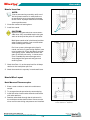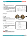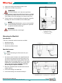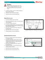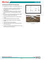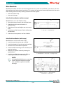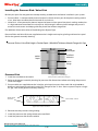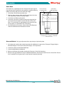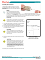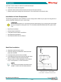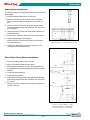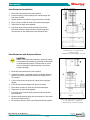
1
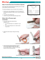
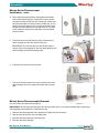
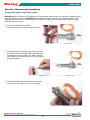
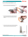
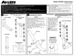
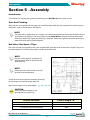
®
Assembly
Section 5 - Assembly
Introduction
This section is a step-by-step guide to assembling your Mold-Masters hot runner system.
Gate Seal Finishing
Most nozzles are supplied with the gate seal installed (except when the seal requires final machining by a
toolmaker, such as the Hot Valve / Hot Sprue).
NOTE:
The gate seals supplied with your system may need to be adjusted to tolerances based on the material grade and cooling in the cavity. Refer to your Mold-Masters General Assembly Gate Detail
drawing to determine if gate seal finishing is required. Refer to the general assembly drawing to
determine which gating method applies.
Hot Valve / Hot Sprue / F Type
Hot valve and hot sprue gated systems are supplied with gate seals that are oversize in length. They must
be machined prior to installing the nozzle into the nozzle well bore.
NOTE:
Hot sprue also requires completion of
the gate detail. Refer to the nozzle well
detail drawing.
NOTE:
Heat expansion of the nozzle must also
be taken into consideration.
Check the chart on the general assembly drawings
for the length and contact height required.
See Contact Length "H" on table below.
CAUTION:
Ensure the thermocouple is not
damaged during machining
Figure 5-1 Hot Valve / Hot Sprue Gated System
Polymer Structure
Contact Length “H”
Amorphous Filled or Reinforced
4.00
Semi-crystalline Filled or Reinforced
3.00
Crystalline Filled or Reinforced
2.00
Hot Runner User Manual
Revision 12
Not under documentation control if printed. May be revised without notice Electronic version is available at www.moldmasters.com
©05-2010
5-1
®
Assembly
Water Cooled Gate Insert Installation (Option)
Your system may not include a water-cooled gate insert. Refer
to your general assembly drawing.
1
1
The water-cooled gate insert will require final machining.
1. Machine the water-cooled gate insert to final height and
2
then add the gate detail. Refer to your system drawing for
details.
2. Clean the insert-seating bore.
3. Install O-rings onto the water-cooled gate insert.
Figure 5-2 Water Cooled Gate Insert
1. O-Rings 2. Seating Bore
Master-Series Thermocouple
Installation
1. Clean the nozzle thermocouple bore.
Suggestion, for:
• 1 mm thermocouples use a #58 drill in a pin
vise
• 1.5 mm thermocouples use a 1/16 inch drill
in a pin vise
Figure 5-3 Clean thermocouple bore
2. Insert the thermocouple through the flange
bore.
Figure 5-4a
Figure 5-4b
Figure 5-5a
Figure 5-5b
3. Manually bend the thermocouple tip against
your thumb to approximately a 90° angle,
ensuring bend length is sufficient to reach the
bottom of the termocouple bore.
Hot Runner User Manual
Revision 12
Not under documentation control if printed. May be revised without notice Electronic version is available at www.moldmasters.com
©05-2010
5-2
®
Assembly
Master-Series Thermocouple
Installation - con't.
4. Dress thermocouple carefully alongside nozzle body
and install retaining clip(s). Check parts list for recommended number of clips for the nozzle type. Check that
the thermocouple fits into the recess of the clip. It is important that one retainer clip is at the top of the nozzle
to keep the thermocouple inside the bore. This is especially important when thermocouples are assembled
from the front.
Figure 5-6
5. Install the terminal end retaining clip. Check that the
thermocouple fits into the recess of the clip.
IMPORTANT: Ensure the terminal end of the thermocouple stays fully engaged in the slot while bending the
thermocouple at the nozzle flange area.
Figure 5-7
6. Install the clip over the terminal end.
7. Use heat resistant tape to secure the nozzle wires and
Figure 5-8
thermocouple wires just above or below the insulator
pod.
Master-Series Thermocouple Removal
Figure 5-9
(for non-front mounted thermocouples)
IMPORTANT: Removing thermocouples will damage them and is not recommended unless replacing a
damaged thermocouple with a replacement one.
1.
2.
3.
4.
Remove the thermocouple from the electrical box and wire channels.
Remove the nozzle from the manifold plate.
Remove the thermocouple retaining clips.
Remove the thermocouple.
Hot Runner User Manual
Revision 12
Not under documentation control if printed. May be revised without notice Electronic version is available at www.moldmasters.com
©05-2010
5-3
®
Assembly
Dura Line Thermocouple Installation
This page only applies to legacy Dura nozzles.
Mold-Masters Dura systems are supplied with an appropriate bending tool. Any questions regarding bending tools, please contact your Mold-Masters representative. Make sure that correct bending tool is used.
Each different type of Dura™ Nozzle requires a different bending tool. The correct bending tool was supplied with your hot runner.
1. Clean nozzle thermocouple bore.
Place thermocouple through flange of nozzle.
Figure 5-10a
Figure 5-10b
2. Place the end of the bending tool all the way over
the end of the thermocouple. While supporting the
thermocouple, create a 180° “fish hook” with the
tool. Make sure the bending tool is snug up against
the thermocouple.
Figure 5-11a
Figure 5-11b
3. Insert the bent thermocouple end into the nozzle
mating hole and make sure it is fully engaged.
Figure 5-12
Hot Runner User Manual
Revision 12
Not under documentation control if printed. May be revised without notice Electronic version is available at www.moldmasters.com
©05-2010
5-4
®
Assembly
Dura Line Thermocouple Installation - con't.
4. Make sure the thermocouple is fully engaged in the nozzle
body while bending the thermocouple at the flange.
Figure 5-13a
Figure 5-13b
5. Press thermocouple downwards to sit against terminal end
and secure to side of terminal end with heat resistant tape
to ensure it does not become pinched between nozzle and
manifold.
Figure 5-14
6. Use heat resistant tape to secure the nozzle wires and thermocouple wires just above or below the insulator pod. The nozzle
is ready for assembly with thermocouple fully installed.
Figure 5-15
Hot Runner User Manual
Revision 12
Not under documentation control if printed. May be revised without notice Electronic version is available at www.moldmasters.com
©05-2010
5-5
®
Assembly
Nozzle Insertion
NOTE:
rior to commencing assembly verify maniP
fold and nozzle cutouts in mold plates are
to specification to ensure proper clearance
to hot runner. Improper clearance will affect
system performance.
1. Clean the nozzle well seating bore.
2. Install the nozzle.
CAUTIONS:
Systems
with gate seals that are not accessible when fully assembled require the gate
seals to be torqued hot prior to installation.
Mold plate needs to be in horizontal position
when inserting nozzles. Care must be taken
when handling the nozzles.
For Liner systems, damage to the tip of a
nozzle can result in gate vestige. Special care
must be take with F-type, Hot Sprue and Hot
Valve gating styles, where the transfer seal
goes up into the part cavity. In these cases
care is needed to prevent damage to the
sharp edge of the gate seal and gate seal
receiving bore.
1
Figure 5-16 Nozzle Well Cleaning
Face 1
Figure 5-17
3. Check that Face 1 is at the same level for all drops
relative to the mold plate split line.
4. Check that nozzle sits squarely in nozzle well bore.
Nozzle Wire Layout
Back Mounted Thermocouples
1
1. Place a zone number on each wire and thermocouple.
2. Try to organize and tape wires by zone and plug.
3. Install the wires into the wire channels and secure
2
with wire retainers.
4. Feed the wires back through the wire channel in
the mold base to the electrical box. Do not cut the
wires until the remaining components are installed.
Hot Runner User Manual
Figure 5-18 Wiring Layout
1. Wire Channel 2. Retainers
Revision 12
Not under documentation control if printed. May be revised without notice Electronic version is available at www.moldmasters.com
©05-2010
5-6
®
Assembly
Front Mounted Thermocouples
1. Place a zone number on each wire and thermocouple.
2. Try to organize and tape wires by zone and plug.
3. Install the wires into the wire channels and secure
1
with wire retainers.
4. Feed the wires back through the wire channel in the
8
mold base to the Mold Plug. Do not cut the wires
too short. Leave sufficient wire for future maintenance and ease of access.
2
6
Figure 5-19 Thermocouple Layout - Side View
1. Thermocouple 2. Wire Retainer
3. Manifold 4. Manifold Backing Plate 5. Power Wire
6. Mold Plug 7. Electrical Box 8. Manifold Plate
3
7
5
4
Valve Bushings
1
Types of Valve Bushings
2
• Heated
• Non-Heated
Valve Bushing Installation
This procedure applies to valve gated systems that are
bolt-in design. Refer to the parts lists and your general
assembly drawing to determine if your system has a
valve bushing.
1. Mount the valve bushing on top of the nozzle.
Figure 5-20 Valve Bushing Types
1. Non-Heated 2. Heated
3
1
NOTE:
he valve bushing for Accu-Valve™ has a
T
locating dowel pin with the mold.
2. Install the locating dowel. Ensure the dowel pin is
2
not too long as this will effect the seal between the
nozzle and the manifold.
NOTE:
required, attach a crane of sufficient If
lifting capacity to the manifold.
Figure 5-21 Valve Bushing
1. Valve Bushing 2. Nozzle 3. Locating Dowel
WARNING:
Make
sure the lifting eyebolt, chain and crane
can support the weight of the m
anifold.
Failure to do so may cause serious injury.
Hot Runner User Manual
Revision 12
Not under documentation control if printed. May be revised without notice Electronic version is available at www.moldmasters.com
©05-2010
5-7
®
3.
Assembly
Apply anti-size on the threads of each screw.
4. Lower the manifold into position.
1
WARNING:
Ensure
the dowels are in the correct positions.
5. Install screws through the manifold and into the manifold
plate (Mounting screw thread must start at the flange seal
level). Refer to the GA drawing(s) for correct screw size.
2
6. Torque screws to value indicated on the general assembly
drawing and secure manifold to the manifold plate.
4
NOTE:
n Bridge Manifold Systems, main to sub-manifold
O
screws should be torqued 1/3 higher than specified
on general assembly drawings.
WARNING:
3
Do not shorten the screw length.
Figure 5-22 Valve Bushing Installation
1. Mounting Screw
2. Manifold 3. Nozzle
4. Valve Bushing
Mounting the Manifold
Introduction
There are 3 methods used to locate the manifold:
1. Manifold Locator
2. Dowel Pin Locator
SURFACE A
SURFACE B
3. Manifold and Slot Locator
X
Manifold Locator
NOTE:
Check GA drawing for information for your
system.
FACE Y
1. For some systems locators are supplied oversize
(X) and must be ground to the same level as the
top of the nozzles. Remove the material from the
bottom face of the locator (FACE Y). This will allow
SURFACE (A) and SURFACE (B) to be at the same
level in the cold condition. However, check the
GA drawing for exception notations.
Figure 5-23 Locator Surface
2
3
2. Blue the manifold locator into the bore to ensure
1
proper seating.
3. Install the locating cam dowel pin.
4. Install the locating cam onto the dowel pin.
Figure 5-24 Manifold with a Locator
1. Manifold Locator 2. Locating Cam 3. Dowel Pin
Hot Runner User Manual
Revision 12
Not under documentation control if printed. May be revised without notice Electronic version is available at www.moldmasters.com
©05-2010
5-8
®
Assembly
WARNING:
Make sure the lifting eyebolt, chain and
crane can support the weight of the manifold. Failure to do so may cause serious
injury.
5. If required, attach a crane of sufficient lifting capacity to the manifold.
6. Check for correct seating and height.
7. Check that there are no pinched wires.
Dowel Pin Locator
1. Install the dowel pin into the mold.
2. Check that the dowel pin does not touch the top
2
3
of the manifold.
3. Install locating cam dowel pin.
4. Install the manifold locating cam onto the dowel
1
pin. If required, attach a crane of sufficient lifting
capacity to the manifold.
5. Place the manifold on top of the nozzles and
locating dowel.
6. Check for correct seating and height.
Figure 5-25 Manifold Locating with a Dowel Pin
1. Manifold Locating Dowel 2. Locating Cam 3. Dowel Pin
7. Check that there are no pinched wires.
Manifold and Slot Locator
1. Blue the manifold locator into the bore to ensure proper seating.
2. Install the slot locator into the mold. Ensure
Slot Locator
sufficient gap between the slot locator and the
manifold slot top surface. Under no circumstances should they touch.
3. Place the manifold on top of the nozzles and
manifold locator.
4. If required, attach a crane of sufficient lifting
Figure 5-26 Manifold with Slot Locator
capacity to the manifold.
5. Check for correct seating and height.
6. Check that there are no pinched wires.
Hot Runner User Manual
Revision 12
Not under documentation control if printed. May be revised without notice Electronic version is available at www.moldmasters.com
©05-2010
5-9
®
Assembly
Installing the Manifold Thermocouple
1
This procedure only applies to integrated systems only.
1. Although not necessary, a thermal compound may
2
be applied to the thermocouple tip to ensure a
good contact.
3
2. Insert the thermocouple into the bore. Check that
the thermocouple is touching the bottom of the
hole.
3. Press down on the thermocouple and gently bend
the thermocouple sheath through 90°.
4. Check that the thermocouple sits in the manifold
cutout.
5. Install the thermocouple washer and screw.
6. Install a zone number on each wire and thermo-
4
couple.
7. Tape wires for each zone together.
8. Install the wires into the wire channels and secure
with wire retainers.
Figure 5-27 Thermocouple Installation
1. Thermocouple 2. Screw 3. Washer
4. Assembly
9. Feed the wires back through the wire channel in the
mold base to the electrical box.
Hot Runner User Manual
Revision 12
Not under documentation control if printed. May be revised without notice Electronic version is available at www.moldmasters.com
©05-2010
5-10
®
Assembly
Main Manifolds
Manifolds distribute melt from the inlet component to one or more sub-manifolds. If you have a sub manifold configuration, follow these instructions. This system will have one of two configurations for inlet seals.
Refer to the general assembly drawing to determine which applies.
• Inlet seal without step
• Inlet seal with step
Inlet Seal Installation (without step)
1
Manifolds that use a seal without a step:
1. Place the inlet seal into all sub-manifold inlets.
2. Check that the inlet seal orientation is 2
chamfer down.
3. Check that all inlet seal heights are at the same
level.
Figure 5-28 Inlet Seal without Step
1. Inlet Seal 2. Sub-Manifold
4. Install the manifold locators. Refer to Mounting
the Manifold.
5. Check that all components are free of debris.
Inlet Seal Installation (with step)
3
Manifolds that use inlet seals with a step:
1.
2.
3.
4.
2
Install the step inlet seal to the manifold.
Install the dowel pin into the seal and manifold.
Lower the main manifold into position.
1
Install manifold mounting screws and torque to
required settings.
5. Refer to your general assembly drawing for
specifications.
Figure 5-29 Inlet Seal with Step
1. Sub-Manifold 2. Inlet Seal 3. Locating Dowel
6. Install the manifold thermocouples. Refer to
Installing the Manifold Thermocouple.
NOTE:
1
n Bridge Manifold Systems, mounting
O
screws should be torqued 1/3 higher
than specified on general assembly
drawings.
2
4
3
Figure 5-30 Install Main Manifold
1. Mounting Screws 2. Main Manifold
3. Dowel Pin 4. Inlet Seal
Hot Runner User Manual
Revision 12
Not under documentation control if printed. May be revised without notice Electronic version is available at www.moldmasters.com
©05-2010
5-11
®
Assembly
Installing the Pressure Disk / Valve Disk
Review your parts list and general assembly drawing to determine the feature installed in your system.
• Pressure Disk - Is compressed by thermal expansive forces to form part of the plastic sealing mechanism. Also helps to reduce thermal transfer to a minimum.
• Valve Disk - Is compressed by thermal expansive forces to form part of the plastic sealing mechanism.
It's high tolerance bore allows the valve pin to shift through it without plastic leakage and part of it
enters the melt stream and helps guide the plastic flow without stagnation.
For additional information refer to Establishing Your System Type
Pressure Disks and Valve Disks are supplied oversize in height and require grinding to dimensions specified on the general assembly drawing.
Pressure Disk or Valve Disk Height = Pocket Depth - (Manifold Thickness+Nozzle Flange+Air Gap)
air gap
disk height
manifold
thickness
pocket
depth
nozzle
flange
Pressure Disk
Figure 5-31 Calculating
Pressure Disk / Valve Disk Height
1. Install the manifold to the nozzle.
2. Refer to the general assembly drawing for pressure disk dimensions before calculating the pressure
valve disk height.
3. Pressure disks are supplied oversize in height, grind equal amounts from each side to give 0.00 to
0.025mm cold clearance and retain maximum strength of the ‘V’ form. Some systems require a larger
air gap, refer to the general assembly drawing.
Grind equal
amounts
Stone sharp corners
Figure 5-32 Pressure Disk
4. Remove the sharp corners after grinding.
5. Install the pressure disk spring dowel to the manifold.
6. Install the pressure disk to the manifold.
Hot Runner User Manual
Revision 12
Not under documentation control if printed. May be revised without notice Electronic version is available at www.moldmasters.com
©05-2010
5-12
®
Assembly
Valve Disk
Valve disks are supplied oversize in height and require grinding to dimensions specified on the general assembly drawing
before calculating the pressure valve disk height.
Ensure correct
air gap per GA
1. Grind the valve disk on top side only.
2. Remove sharp corners after grinding and clean the valve
Clean bore
after grinding
4
disk, especially inside the valve pin bore.
3. Install the manifold to the nozzle.
4. Install the valve disk. Check that the arrow engraved on
1
3
the valve disk corresponds to the direction of the melt
flow. Ensure correct air gap between the valve disk and
the top plate, as specified in the GA drawing.
5. For information on removal, refer to Valve Disk Removal,
within the Maintenance Procedures section.
2
Figure 5-33 Manifold to Nozzle Mounting
1. Spring Dowel 2. Nozzle 3. Manifold
4. Pressure Disk
Alternate Method - Air gap adjustment from top clamp or hydraulic plate
1. Calculate and machine the nozzle bore seat with additional air gap value. (Example: Flange Height +
2.
3.
4.
5.
Manifold Height + Pressure or Valve Disk height + Air Gap Value)
Install the nozzle into the Manifold Plate.
Install the Manifold to the Nozzle.
Refer to the General Assembly drawing for Pressure / Valve Disk locations.
Measure the gap between the top of the Manifold Plate and the top of the Pressure / Valve Disk. Ensure
that it matches the air gap value on the General Assembly drawing.
Hot Runner User Manual
Revision 12
Not under documentation control if printed. May be revised without notice Electronic version is available at www.moldmasters.com
©05-2010
5-13
®
Assembly
Installing Heater Plates
These procedures apply to systems with external heater plates. Refer to the general assembly
drawing to determine which heater plate applies to
your system.
NOTE:
CAUTION:
H
eater plates are controlled by a thermocouple
located in the heater plate. Do not control the
heater plate from a thermocouple in the manifold.
urrent bronze heater plates are diC
rectly interchangeable with previous
Figure 5-34 Heater Plate and Thermocouple
copper or aluminum based plates that
may exist on your Mold-Masters system. However, when multiple heater plates are controlled
by one thermocouple, these heater plates must be made of the same material, of equal voltage and are located in similar thermal environments.
3
1. Insert the thermocouple into the bore. Ensure the thermocouple is touching the bottom of the bore hole.
2. Press down on the thermocouple and gently bend to 90°.
3. Install the heater plate to the manifold. Refer to general
5
4
assembly drawing for location.
CAUTION:
1
his is a pinch point area. Use caution when
T
installing the heater plate to the manifold plate.
Failure to do so could result in damage to the
thermocouple.
4. Secure the heater plate to the manifold. Use anti-seize on
threads.
CAUTION:
2
Figure 5-35 T/C Installation
1. Thermocouple 2. Manifold
3. Mounting Screw 4. Heater Plate
5. Thermocouple Bore Hole Plate
o not over-tighten the mounting screws. This
D
could result in the heater plate losing contact with the manifold plate. Refer to the general
assembly drawing for the correct torques. It is
recommended that the heater plate wires be
isolated and grouped so that they do not have
to be disconnected if the manifold needs to be
dismantled for repair.
The heater plates are supplied with the power wires connect-
Hot Runner User Manual
Revision 12
Not under documentation control if printed. May be revised without notice Electronic version is available at www.moldmasters.com
©05-2010
5-14
®
Assembly
ed. Place a zone number on each wire and thermocouple.
5. Tape wires for each zone together.
6. Install the wires into the wire channels and secure with wire retainers.
7. Feed the wires back through the wire channel in the mold base to the electrical box.
Installation of Inlet Components
The following procedures refer to different system configurations. Refer to your parts list and general assembly drawings to determine your system type.
•
•
•
•
•
CAUTION:
or all inlet components it is important that the mold locating ring is touching the inlet compoF
nent just enough for sealing the area. This should be doubled checked with the system drawings.
Back Plate Installation:
Center Heater Installation: Three Piece Center Heater Installation:
Inlet Extension/Installation:
Inlet Extension With Pressure Sleeve
Back Plate Installation
1. Check the machine nozzle radius.
2. Check the seating on the bottom face of the back
1
3. Install the back plate onto the manifold.
4. Install M8 mounting screws through the back plate
2
plate and manifold.
3
to the manifold using anti-seize on threads.
5. Torque screws to value indicated on the GA drawing in a cross pattern, in 5 ft/lb increments.
5
NOTE:
4
he machine nozzle bore should be 1.0mm
T
(0.040”) smaller than the back plate bore.
Figure 5-36 Nozzle Pad Installation
1. Mounting Screw 2. Nozzle Radius
3. Back Plate 4. Manifold 5. Bottom Face
Hot Runner User Manual
Revision 12
Not under documentation control if printed. May be revised without notice Electronic version is available at www.moldmasters.com
©05-2010
5-15
®
Assembly
Center Heater Installation
The center heater may require the machine nozzle radius
to be added.
3
1. Place the center heater on the manifold.
2. Rotate the center heater to align with the tapped
holes in the manifold and align terminals with cut
out.
3. Install mounting screws through the center heater
into the tapped holes of the manifold. Use anti-seize
on the screws.
4. Torque screws to values indicated on the general assembly drawing.
5. Place zone number on each wire and thermocouple.
6. Tape wires for each zone together.
7. Install the wires into the wire channels and secure
with wire retainers.
8. Feed wires back through the wire channel in the
1
2
Figure 5-37 Center Heater Assembly
1. Thermocouple 2. Center Heater 3. Screw
mold base to the electrical box.
1
Three Piece Center Heater Installation
1. Install the back plate on the manifold.
2. Mount the center heater on back plate.
3. Although not necessary, a thermal compound may
7
6
be applied to the thermocouple tip to ensure a good
contact.
2
4. Install the thermocouple.
5. Install the cover plate.
6. Install M8 mounting screws through the cover plate
into the tapped holes of the manifold. Use anti-seize
on screws.
7. Torque screws to values indicated on the general as-
3
5
sembly drawing.
4
Figure 5-38 3 Piece Assembly
1. Screw 2. Center Heater 3. Back
Plate 4. Manifold 5. Ground Wire
6. Thermocouple 7. Cover Plate
Hot Runner User Manual
Revision 12
Not under documentation control if printed. May be revised without notice Electronic version is available at www.moldmasters.com
©05-2010
5-16
®
Assembly
Inlet Extension Installation
1
1. Place the inlet extension on the manifold.
2. Install mounting screws through the nozzle flange and
3.
4.
5.
6.
2
6
into the manifold.
Torque screws to manifold using anti-seize on threads.
Place a zone number on each wire and thermocouple.
3
Tape wires for each zone together.
Install the wires into the wire channels and secure
with wire retainers. Feed the wires back through the
wire channel in the mold base to the electrical box.
5
4
Figure 5-39 Inlet Extension
1. Extension Tip 2. Inlet Extension
3. Thermocouple
4. Manifold 5. Nozzle Flange 6. Screw
Inlet Extension with Pressure Sleeve
CAUTION:
Always
install the inlet extension, pressure sleeve,
clamp plate and locating ring with the mold plates
in the horizontal position. Failure to do so could
result in damage to the components and cause
material leakage.
1. Place the inlet extension on the manifold.
2. A pressure sleeve is supplied oversize in length. Refer to
general assembly drawing to determine length of pressure sleeve.
4
3
1
3. Cut the inlet extension pressure sleeve to the required
4.
5.
6.
7.
2
height.
Chamfer the outside edge of the pressure sleeve.
Place zone number on each wire and thermocouple.
Tape wires for each zone together.
Install the wires into the wire channels and secure with
wire retainers.
8. Feed the wires back through the wire channel in the mold
base to the electrical box.
9. For electrical checks, refer to the Electrical Testing section.
Hot Runner User Manual
Figure 5-40 Inlet Extension with Sleeve
1. Inlet Extension 2. Manifold
3. Extension Tip 4. Pressure Sleeve
Revision 12
Not under documentation control if printed. May be revised without notice Electronic version is available at www.moldmasters.com
©05-2010
5-17