1
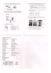
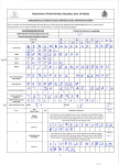
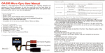
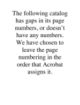
PROFESSIONAL MIDI BASS
Owner's Manual
Written by Don Bird
Art Prod. by Brad Cox
ALL RIGHTS RESERVED
Copyright 1987 by 360 SYSTEMS
PREFACE
360 Systems has been in the business of providing unique and useful products for the modern Musician
and Comwser for over 16 vears. We relv on feedback from our customers to helo us continue the
developient of innovative and affordabli products that best meet their needs. piease feel free to
address any comments you may have regarding 360 Systems and its present or future products to:
360 Systems, 18740 Oxnard Street, Tarzana, California 91356
TABLE OF CONTENTS
INTRODUCTION
FEATURES AND SPECIFICATIONS
SECTION 1
1.1
1.2
1.3
1.4
1.5
SECTION 2
2.1
2.2
2.3
2.4
2.5
2.6
2.7
GElTlNG STARTED
Cautions
Rear Panel Connections
MIDI Connections
Power Up
Display Adjustment
OPERATIONAL OVERVIEW
Volume
Display
Arrow Buttons
Master
Select Sound
Store
Recall
SECTION 3
PROGRAMMING OVERVIEW
SECTION 4
PROGRAMMING MASTER FUNCTIONS
Tune
Transpose
Set Up
4.3-1 Keyboard Transpose Interval
4.3-2 MlDl Channel
4.3-3 MlDl Pitch Bend Enable
4.3-4 MlDl Patch Change Enable
4.3-5 MlDl Volume Enable
4.3-6 Note Priority
4.3-7 Voice Cascade Mode
4.3-8 Test Note
4.3-9 Memory Protect
4.1
4.2
4.3
SECTION 5
5.1
5.2
5.3
5.4
SECTIPN 6
6.1
6.2
SECTION 7
7.1
7.2
7.3
PROGRAMMING SELECT SOUND FUNCTIONS
Lower and Upper Sound Select
Accent Sound Select
Modify
5.3-1 Volume
5.3-2 Decay
5.3-3 Release
5.3-4 Filter Adjust
5.3-5 Velocity
5.3-6 Accent Velocity
Zone
STORE 1 RECALL
Store
Recall
APPENDIX
Alternate Sounds
Installing Alternate Sound Chips
DefauR Settings
INTRODUCTION
After the success of our original Midi Bass, we listened and learned a great deal about what people wanted
in a "bass line" sampler. As a resuit, our design team has incorporated many new features into a product
that is useful and easy to operate. Professionat Mldl Bass was designed to provide sampled sounds
so accurate and realistic that they put the actual bass instrument at your fingertips, while freeing up other
synths and samplers to be used to their fullest potential. Ideal for recording, sequencing and live
performance, the Professional Mldl Bass interfaces with MlDl controllers such as keyboards,
pedalboards, MlDl guitars or basses. This new rack mount version provides a megabyte of internal EPROM
sound memory capacity, improved signal-to-noise ratio (in excess of 90 dB) and two 12 mHz computers to
handle internal operations. All of this and more adds up to a pmduct we think will be a vital part of
everyone's set-up for many years to come.'
SPECIFICATIONS
ENCLOSURE: Rackmount or tabletop.
DIMENSIONS: 1.70 x 19 x 7.50 (HWD)
SHIPPING WEIGHT: 6 bs.
POWER: 1201240 volts, 50160 Hz., 1OW
0PT.POWER: 100V/60Hz, 230V150Hz
FUSE: Internal
AUDIO OUT: 114" phone, nominal 1 volt.
INPUT: MlDl IN
PATCH MEMORY: lntemal RAM (non-volatile)
EPROM MEMORY CAPACITY: 16 chips
DISPLAY: 2 line, 16 character LCD
FEATURES
MIDI: In, Thru, Out (2nd Voice Cascade)
MlDl RECEIVE: All, 1-16
OMNl MODE: On IOff
NOTE PRIORITY: Last, Low, High
VOICES: Monophonic
PRESETS: 30 user programmable
ZONES: 2 user programmable
TRANSPOSE: 63 semitones
ZONE TRANSPOSE: t 63 semitones
FINE TUNING: 1 semitone, digital
+
+
ACCENT SOUNDS: 1 per zone
VELOCITY. On IOff
VELOCITY CROSSOVER: Variable 0-127
DECAY AND RELEASE: Variable
SUSTAIN: MlDl
PITCH BEND: On IOff
FILTER ADJUST: 5 1/3 octaves
VOLUME: Variable 0-100
MIDI VOLUME: On / Off
Addfiional sounds are available from the Alternate Sound Library for the Professional Midi Bass.
For a listing of sounds and a demonstration tape, send $5.00 along with a return address to:
360 Systems, 18740 Oxnard Street, Ta~zana,CA 91356.
Section 1 GETTING STARTED
1. Audio Out
2. Cover Plate Screws
3. Viewing Angle Adjust
4. MIDIThnr
5. MlDl In
6. MlDl Out (2nd Voice Cascade)
1.1 CAUTIONS
IF ALTERNATE SOUND CHIPS HAVE BEEN PURCHASED AND ARE TO
BE INSTALLED, REFER TO SECTION 7.2 INSTALLING ALTERNATE
SOUND CHIPS BEFORE INSTALLATION OR OPERATION OF THE
PROFESSIONAL MlDl BASS.
DO NOT REMOVE OR DEFEAT THE GROUNDING PRONG ON THE AC
POWER CORD. A SERIOUS SHOCK HAZARD CAN RESULT FROM
FAILING TO CONNECT THE AC POWER CORD TO A PROPERLY
GROUNDED ELECTRICAL OUTLET. NEVER USE THE PROFESSIONAL
MlDl BASS NEAR DAMP OR WET ENVIRONMENTS.
BEFORE CONNECTING ANY CABLES AND
MAKE SURE POWER IS
M A T THE PROFESSIONAL MIDI BASS HAS THE PROPER VOLTAGE
RATING FOR THE COUNTRY OR AREA IN WHICH IT IS TO BE
OPERATED.
1.2 Rear Panel Connections
1)
Connect the Pro Midi Bass power cable to a standard grounded wall outlet.
Versions are available for 100, 120,230 and 240 volts.
2)
Using a 114" audio cable, connect AUDIO OUT (1) to an input on your amp or mixer.
1.3 MIDI Connections
1)
Using a standard 5-pin MlDl cable, connect the MlDl OUT of a keyboard,
pedalboard, sequencer or other MlDl contmller to the MlDl IN jack (5) on the rear
panel of the Pro Midi Bass. When first powered up, the Pm Midi Bass is set to
receive on MlDl Channel "ALL" (Omni mode). To change the MlDl receive
channel, refer to Section 4.3-2 MlDl Channel.
2)
To "echo" MlDl information down the line to other devices, connect the MlDl M R U
jack (4) of the Pm Midi Bass to the MlDl IN jack on another MlDl device.
3)
Two Pro Midi Basses can play multiple notes (polyphonic operation) ifthe
2nd Voice Cascade is used. Just connect a MlDl cable from the MlDl OUT jack (6)
on the Pm Midi Bass to the MlDl IN jack (5) of another. (See Section 4.3-7)
1.4 Power Up
m e power switch is located at the len side of the front panel. Once acables have been connected, turn
power on by depressing the bottom half of the switch. The display should read:
Pro MidiBass 1.3
Sounds Avail: 8
Pro Midi Bass contains 8 standard factory sounds on EPROM chips. Additional empty chip sockets are
provided for the user to add any desired combination of chips from the 360 Systems Alternate Sound
Library. The total number of sounds on-line will vary depending upon how many chips are contained in the
Pro Midi Bass and the number of sounds on each chip. (Some chips may contain only one sound, others
may hold two or more.) In any case, the display will always indicate the number of sounds currently on-line
each time the Pm Midi Bass is powered up.
1.5 Display Adjustment
When mountingthe Pm Midi Bass in a rack, it may be desirable to adjust the angle of the LCD display for
optimum viewing. Just turn the VIEWING ANGLE ADJUST screw on the rear panel with a small flat-blade
screwdriver. (See Fig. 1)
Section 2 OPERATIONAL OVERVIEW
6 5
1. Display
2. Arrow Buttons
3. Master
3a. Set Up
3b. Tune
X.Transpose
2.1 Volume
4. Select Sound
4a. Lower
4b. Upper
4c. Accent
4d. Modify
4e. Zone
5. Store
6. Recall
7. Volume Knob
8. Power Switch
Eia
This knob adjusts the output level of all sounds and patches in the Pro Midi Bass and is n ~memorized
$
when storing patches. Use the Volume function contained in the Modify section to balance relative levels
of sounds when creating custom patches.
2.2 Display
When performing any operation on the Pm Midi Bass, it will read out on the 2 line. 16 character LCD
Display. During programming, the Display will always indicate the sound(s) in use or the modify (edit)
functions being periorrned as well as their currently selected values.
2.3 Arrow Buttons
The two Arrow buttons (upidown) located to the rimof the Display are used for selection of data. When
selecting a sound or modifying a patch, the upldown Anows are used to toggle through all of the available
options. Press and hold Arrow buttons for fast scanning of value options. Since the options indicated in
the Display are always active, it is possible to audition the effect of various sounds or value options.
2.4 Master
All functions in the Master section are "global", meaning they will affect the overall response of the Pro Midi
Bass. These settings are not stored within individual patches. Once a value has been selected for any
Master function, that value will be retained in internal memory and will not be affected when patches are
recalled. Some Master functions are non-volatile (i.e. their vaiues will be retainedwhen Pro Midi Bass is
turned off), others are volatile and will be reset to their default values when Pro Midi Bass is turned off. For
a listing of which functions are volatile or non-volatile, refer to Section 7.3 Default Settings.
2.5 Select Sound
All functions contained in this section can be saved to a patch number for later recall as custom patches.
Lower, Upper and Accent are used to view, audition and select the sounds to be played on the Pro Midi
Bass. The Modify and Zone buttons are used to affect the performance or response characteristics of any
selected sounds and their placement or "mapping" onto a controller keyboard, guitar or sequencer.
2.6
Store
There are 30 memory locations available to store custom patches. Once a patch has been stored, it can be
recalled for later use or modiiied and stored again in the same or a different location. Patches stored in
-am--, ,.rill ho rotainod whan mwer i
s turned off.
2.7 Recall
Recall is used to call up patches previously stored in memory. When a patch is recalled, it will immediately
activate a Lower, Upper and Accent sound combination, along with all Modify and Zone information
originally saved to that patch number. There are no factory preset patches in the Pro Midi Bass. When
attempting to recall a patch number that has never been used to store information, the Display will indicate:
Recall Patch: xx No Patch Saved.
Section 3 PROGRAMMING OVERVIEW
The Professional Midi Bass is programmable, meaning that combinations of sounds and other functions
that affect performance may be altered by the user and stored in memory for use in future applications.
The Arrow buttons are used to scroll through and select from sound and value options that are accessed
through other buttons on the front panel. All sounds and values are in effect immediately when they
appear on the display, and will remain in effect until they are replaced or re-programmed. Refer to Section
7.3 Default Settings for a listing of functions, their default settings, value ranges, and whether they are
volatile or non-volatile.
There are three main groups of buttons which allow access to the programmabie functions of the Pro Midi
Bass. They are:
1)
MASTER
Global settings used for general Set Up purposes. They may be stored in
internal memory, but cannot be saved to individual patch memories. For
convenience, some Master functions will reset to their default values when
the Pro Midi Bass is turned off.
2)
SELECT SOUND
Used to create and modify combinations of sounds and assign or "map" them
to zones. These settings can be stored in the internal non-volatile patch
memory and recalled for future use.
3)
STORE & RECALL
Used for storing individual user-created patches to memory for instant recall
during performance or normal operating situations.
Section 4 PROGRAMMING MASTER FUNCTIONS
The three main function buttons in the MASTER section are:
1. TUNE
2. TRANSPOSE
3. SET UP
4.1 Tune
Value range
-63 to +63
Default:
0
Tuning is variable over a single semitone range up or down.
1.
2.
3.
4.
Press TUNE.
Display will prompt: Tuning Adj: 0
(Calibration to A440)
Use ARROW buttons to select desired value from -63 to +63.
Press any other button on the front panel to exit this function.
4.2 Transpose
Value range: Enabled / Disabled
Default:
Disabled
This is a global Transpose and will shii the range of all notes on the Pro Midi Bass equally. It is
independent of the Zone Transpose functions and will not affect the Transpose lntewal amounts selected
for each Zone although it will uniformly shii the note ranges for each Zone simultaneously. When
Transpose is Enabled, it allows the transposition selected using the Keyboard Transpose Interval function
(Section 4.3-1) to become active. When Transpose is disabled, it defeats the Transpose Interval and
returns the Pro Midi Bass to normal tuning.
1.
2.
3.
To activate, press TRANSPOSE.
LED will light and display pmmpts: Keybd Transpose: Enabled
To defeat, press TRANSPOSE again. LED will turn off and display pmmpts:
Keybd Transpose: Disabled
4.3 Set Up
Repeatedly pressing the SET UP button will allow for selection of the following functions:
1. Keyboard Transpose Interval
2. MlDl Channel
3. MlDl Pitch Bend Enable
4. MlDl Patch Change Enable
5. MlDl Volume Enable
6. Note Priority
7. Voice Cascade Mode
8. Test Note
9. Memory Protect
These are global functions and remain effective independently of patch memory. Once a particular
function is selected, use the ARROW buttons to toggle through the value options. The last value
indicated on the display will remain effective until it is re-programmed. Exit any function by pressing the
SET UP button again or by pressing any other button on the front panel.
4.3-1 Keyboard Transpose lntewal
Value Range: +63 to -63
Default:
0
Remember that since this function is included in the Master section, it is a global transpose and will affect all
sounds equally. Once a Transpose lnterval is selected, the TRANSPOSE button on the front panel may
be used to enable or disable it. This feature can be very useful when interfacing with other devices such
as MlDl pedals or small keymards with "hard assigned" note numbers.
1.
2.
3.
Press SET UP button until the display prompts:
Keybd Transpose Interval: 0
Use ARROW buttons to adjust value up or down by semitones.
Press any other button on the front panel to exit this function.
NOTE: If the Transpose LED is not on, no change will occur because Transpose is disabled. Press
TRANSPOSE, LED will light and Transpose lnterval will become effective.
4.3-2 MIDI Channel
Value range:
ALL, 1-16
Default:
ALL
This function allows selection of the MlDl channel number that the Pro Midi Bass receives information on.
ALL (Omni) causes the Pro Midi Bass to respond to all MlDl information it receives, no matter what the
transmitted channel number may be. Selecting an individual channel number causes the Pro Midi Bass to
play notes it receives on that channel only, ignoring all others.
1
2.
3.
Press the SET UP button repeatedly until the display prompts:
MIDI Chan: ALL
Use the ARROW buttons to select the desired channel ALL, 1-16.
Press any other bution on the front panel to exit this function.
NOTE: Some synths, notably the Yamaha DX-7, can only transmit on MlDl channel #I.
The Pro Midi Bass
must be set to either ALL or 1 to respond to this type of controller.
4.3-3 MlDl Pitch Bend Enable
Value range:, ON I OFF
Defauft:
ON
Pro Midi Bass will respond to pitch bend informationfrom a keyboard, sequencer or other controller when
ON is selected for this function. The Pro Midi Bass has a fixed bend range of three semitones (minor
third), SO make sure that the controller is set for an equal amount of bend or some unusual effects may
resun. When OFF is selected, Pro Midi Bass will not respond to pitch bend information, but will echo pitch
bend informationto other MlDl devices.
1.
2.
3.
Press the SET UP button repeatedly until the display prompts:
MlDl PRch Bend Enable: ON
Use the ARROW buttons to select ON or OFF.
Press any other button on the front panel to exit this function.
4.3-4 MIDI Patch Change Enable
Value range: ON I OFF
Default:
ON
When calling up patches with an external MlDl device, selecting ON will allow the Pro Midi Bass to receive
MlDl patch change information on the channel selected using the MlDl Channel function (Section 4.3-2).
Selecting OFF will disable MlDl patch change messages but the Pro Midi Bass will continue to receive ail
other MlDl information.
Press the SET UP button repeatedly until the display prompts:
MlDl Patch Chng Enable: ON
2. Use the ARROW bunons to select ON or OFF.
3. Press any other button on the front panel to exit this function.
1.
NOTE: If MlDl Channel (Section 4.3-2) is set to ALL, the Pro Midi Bass will receive patch change
commands on all channels when MlDl Patch Change Enable is ON.
4.3-5 MlDl Volume Enable
Value range: ON / OFF
Default:
OFF
In order for the Pro Midi Bass to receive MlDl Volume messages, this function must be set to ON. New
volume messages will only affect notes played after the Pro Midi Bass has received the new volume
message.
I. Press the SET UP button repeatedly until the display prompts:
MlDl Volume Enable: OFF
2. Use the ARROW buttons to select ON or OFF.
3. Press anv other button on the front panel to exit this function.
4.3-6 Note Priority
Value range: LAST, LOW, HIGH
Default:
LAST
Since Pro Mkii Bass is monophonic, it needs to know which note it should play when several are received.
In other words, it must know which note to give priority to.
1.
2.
3.
Press the SET UP button repeatedly until the display prompts:
Note Priority: Last Note
Use the ARROW buttons to select Last, Low or Hlgh.
Press any other button on the front panel to exit this function.
LAST NOTE- For most performance work and especially when using a sequencer, select this option. This
will insure that every new note played will sound, even it old notes are still being held down. This mode
allows for fast and even somewhat inaccurate playing.
LOW NOTE- It is often useful to extract the lowest note played within a chord and ignore all others. Low
mode is particularly useful in two-handed performances when the left hand is playing open-voiced pads
and the Pm Midi Bass is set to play only in the lowest range of the keyboard.
HIGH NOTE- In High mode the Pro Midi Bass will play the highest note within a chord. By voicing chords
suitably, it can play a predictable harmony line or melody llne within the chord. High mode also works weil in
two-handed performances, when the Pro Midi Bass is set to play the upper portion of the keyboard.
4.3-7 Voice Cascade Mode
Value range: ON IOFF
Default:
OFF
By connecting two Professional Midi Basses together via the MlDl OUT jack, notes can be played and
triggered in a polyphonic manner. Once the Pro Midi Bass has received and triggered an initial note, a
second incoming note will be passed via the MlDl OUT port to the next Pro Midi Bass or other MlDl device
connected. When ON is selected for this function, any incoming note will be played unless a previous
note is still being held. If a previous note is being held, the new note will be passed through the MlDl OUT
port to the next unit "in-line". Any additional information will also be passed to the second unit (i.e.- patch
change, Midi Volume, etc.) When using the 2nd Voice Cascade, make sure that the second Pro Midi
Bass has its Voice Cascade Mode switched to OFF.
1.
2.
3.
Press SET UP button repeatedly until display prompts: Voice Cascade Mode: OFF
Use ARROW buttons to select ON or OFF.
Press any other button on the front panel to exit this function.
4.3-8 Test Note
Value range: Upper, Lower
Default:
Press arrows for sound
The Test Note function provides for audio testing of the Pro Midi Bass output connections. The UP
ARROW button will trigger the currently selected upper sound and the DOWN ARROW will trigger the
lower sound. This function can also be used to determine whether or not an external controller is properly
interfaced with the Pro Midi Bass. If pressing the ARROW buttons triggers a note but no note is heard
when a key is pressed on an external controller, then there is a bad MlDl connection, or one or more of the
Set Up and Zone functions is incorrectly programmed for interface with that controller. (Check to see that
MlDl Channel is correctly assigned and that Zone and Transpose are set to ranges that allow proper
triggering of sounds.) Test Note will trigger the note that is the mid-point of the sample's range, so don't
be alarmed if triggered notes are different pitches.
Press the SET UP button repeatedly until the display prompts:
Test Note: Press arrows for sound
2. Press UP ARROW button to trigger Upper sound.
3. Press DOWN ARROW to trigger Lower sound..
4. Press any other button on the front panel to exit this function.
1.
4.3-9 Memory Protect
Value range: ON / OFF
Default:
ON
Memory Protect prevents the bss of user presets through accidental erasure or re-programming and also
protects against others tampering with stored patches. When Memory Protect is ON, the Store function is
disabled. Since Memory Protect defaults to ON, it must be turned OFF before patches may be stored.
1.
2.
3.
Press the SET UP button repeatedly until the display prompts:
Memory Protect Switch: ON
Use the ARROW buttons to select ON or OFF.
Press any other button on the front panel to exit this function.
Section 5 PROGRAMMING SELECT SOUND FUNCTIONS
Pro Midi Bass allows for selection of four sounds to be on-line at one time (Lower, Lower Accent, Upper
and Upper Accent) although only one sound at a time may be played. LOWER, UPPER and ACCENT
buttons are used to select the sounds you wish to play. MODIFY and ZONE buttons are used to select
options that affect the performance or response characteristics of the various sounds. Lower and Upper
sounds correspond to the Lower and Upper Zones defined with the Zone function (Section 5.4). For
each main (Lower, Upper) sound selected, a separate Accent (Lower, Upper) sound may also be selected
Any sound becomes effective as soon as its name appears on the display and will continue to be effective
(along with any modifications made using Modify or Zone functions) unt~la new sound is selected or
another patch is recalled. All Selea Sound functions may be stored in non-volatile patch memory. The
various sound and value combinations created with these functions may be stored in one of the 20 patch
locations using the procedures described in Section 6.1 Store.
-
5.1 Lower and Upper Sound Select
When first turned on, the Pro Midi Bass will assign Upper and Lower sounds within the default limit points
for Upper and Lower Zones. To change the "mapping" of the sounds refer to Section 5.4 Zone.
I. Press LOWER button. LED will light. Display prompts:
2.
3.
1.
2.
3.
Lower Sound: xxx
Use the ARROW buttons to scroll through and select a sound.
Press any other button on the front panel to exit this function.
Press UPPER button. LED will light. Display prompts:
Upper Sound: mx
Use the ARROW buttons to scroll through and select a sound.
Press any other butfon on the front panel to exit this function.
NOTE: Whenever a new sound is selected, the default settings for that sound will replace any previously
programmed settings that have not been saved to patch memory.
5.2 Accent Sound Select
Since Accent sounds will only be heard when a note is played with enough velocity, the Accent Velocity
function in the Modify section (5.3-6) may be used to lower the velocity crossover point and make it easier
to audition Accent sounds. If no Accent sound is desired, select the Accent sound that matches the
Upper or Lower sound selected.
Press LOWER button. LOWER LED will light.
Press ACCENT button. ACCENT LED lights, display prompts:
Lower Accent: mx
3. Use the ARROW buttons to scroll through and select Accent sound.
4. Press any other button on the front panel to exit this function.
1.
2.
P
1.
2.
3.
4.
Press UPPER button. UPPER LED will light.
Press ACCENT button. ACCENT LED fights, display prompts:
Upper Accent: xxx
Use the ARROW buttons to scroll through and select Accent sound.
Press any other button on the front panel to exit this function.
5.3 Modify
Pressing the MODIFY button when the UPPER or LOWER Select Sound LED is lit will cause the display to
show the first of several fundions that are user-adiustable. Subsequent button pushes will step through
the available functions. They are:
P
1.
2.
3.
4.
Volume
Decay
Release
Filter Adjust
Velocity
5.
Pressing the MODIFY button when the ACCENT LED is lit will display the first of several user-adjustable
functions for that (Upper or Lower) Accent sound. Subsequent pressing of the MODIFY button will step
through additional functions for accent sounds:
1.
2.
3.
4.
5.
Volume
Decay
Release
Filter Adjust
Accent Velocity
When programming values in Modify, the UPPER, LOWER and ACCENT LEDs will indicate which sound is
being affected and the display will show the name of that sound,as well as the modifier being used and its
currently selected value. Selecting any new value using the ARROW buttons will automatically activate
that value for audition purposes. Combinations of values for particular sounds may be saved using the
Store function (Section 6.1). Press any other button on the front panel to exit any of these functions. The
last value shown in the display will remain effective.
CAUTION: If sound and value combinations are not stored as patches, the Pro Midi Bass will reset to
defauk values when turned off or when a new sound is selected.
5.3-1 Volume
Value range:
0 - 100
Default:
100
Used to balance relative levels between Lower, Upper and Accent sounds.
1.
2.
3.
4.
Select Lower, Upper or Accent sound to be modified.
Press MODIFY button, display will prompt:
Volume: 100
Use ARROW buttons to select 0 -100.
Press any other button on the front panel to exit this function.
5.3-2 Decay
Value range:
0 -7
Default:
Varies by sound.
Decay affects the level of the sound while a key is being held down. Lower values will shorten Decay time.
Higher values will extend Decay time. Defauk value is pre-programmed in each sound chip.
1.
Select Lower, Upper or Accent sound to be modified.
2. Press MODIFY button repeatedly until display prompts:
Decay: xxx
3. Use ARROW buttons to select 0 7.
-
4.
Press any other button on the front panel to exit this function.
5.3-3 Release
Value range: 0 7
-
Default:
Varies by sound.
Release affects the level of the sound after a key has been released. Lower values will shorten release
time. Higher values will extend release time. Default value is pre-programmed in each Sound chip.
1.
2.
3.
4.
Select Lower, Upper or Accent sound to be modified.
Press MODIFY button repeatedly until display prompts:
Release: xxx
Use ARROW buttons to select 0 7.
Press any other button on the front panel to exit this function.
-
5.3-4 Filter Adjust
Value range:
0 to -64
Default:
0
This will change the apparent "timbre" of a sound. 0 =filter open. As negative numbers increase, filter is
closed down for darker tones.
1. Select Lower, Upper or Accent sound to be modified.
2. Press MODIFY button repeatedly until display prompts:
Filter Adj: xxx
3. Use ARROW buttons to select 0 to 64.
4. Press any other button on the front panel to exit this function.
5.3-5 Velocity (Lower and Upper sounds only.)
Default:
Value range: ON 1 OFF
ON
ON allows Pro Midi Bass to respond to velocity informationfrom velocity sensitive controllers. In situations
where velocity sensitivity is not desired, select OFF for this function.
Select Lower or Upper sound to be modified.
Press MODIFY button repeatedly until display prompts:
Velocity: ON
3. Use ARROW buttons to select ON or OFF.
4. Press any other button on the front panel to exit this function.
1.
2.
5.3-6 Accent Velocity (Accent sounds only.)
Value range:
0 - 127
Default:
120
Any time a note is played with a velocity greater than the amount set, an Accent sound wiil be triggered
instead of an Upper or Lower sound. When Velocity (5.3-5) is set to OFF, the Accent Velocity wiil continue
to operate and trigger Accent sounds at a constant level.
Select Accent sound to be modified.
Press MODIFY button repeatedly until display prompts:
Accent Vel: 120
3. Use ARROW buttons to select 0 - 127.
4. Press any other button on the front panel to exit this function.
1.
2.
5.4 Zone
Zones are created to define the note range over which an Upper or Lower sound and its associated
Accent sound will be "mapped" onto a keyboard or other controller. Separate Zone mapping may be
created for each patch in the Pro Midi Bass. Upper and Lower limits define the "width" of a Zone and the
actual pitch range is defined with the Zone Transpose Interval. When firs powered up, the Pro Midi Bass
will defauh to settings of C1 - 82 at concert pitch for the Lower Zone, and C3 - D5 at concert pitch for the
Upper Zone. However, if a Zone has been created outside of the note range for a particular sample, no
sound will be heard and it will be necessary to adjust the Zone Transpose Interval to shift the sample into
the proper note range. If certain Zone values do not need to be re-programmed, they can be stepped
over without entering a new value by simply pressing the ZONE button to move to the next screen.
To Set LOWFR 70NF.
I . Press LOWER button. LED will light.
2. Press ZONE button. Display prompts:
Lower Zone Set Play Bottom Note
3. Play desired bottom note for Lower Zone on controller.
4. Display will then prompt:
Lower Zone Set Play Top Note
5. Play desired top note for Lower Zone on controller.
6. Display will then prompt:
Lower Zone Set Trnspose Int: 0
7. Use ARROW buttons to select the desired Transpose Interval from +63
semitones to -63 semitones.
8. Press any other button on the front panel to exit this function.
w e t UPPFR ZONF.
1. Press UPPER bufton. LED will light.
2. Press ZONE button. Display prompts:
Upper Zone Set Play Bottom Note
3. Play desired bottom note for Upper Zone on controller.
4. Display will then prompt:
Upper Zone Set Play Top Note
5. Play desired top note for Upper Zone on controller.
6. Display will then prompt:
Upper Zone Set Trnspose Int: 0
7. Use ARROW buttons to select the desired Transpose Interval from +63
semltones to -63 semitones.
8. Press any other button on the front panel to exit this function.
Section 6 STORE 1 RECALL
6.1
Store
The Store function allows for user created settings and sound combinations to be saved as individual
patches for later recall. STORE will save Lower and Upper sounds and any corresponding Accent voices
simu~aneously,along with Modify and Zone informa'on. There are 30 memory locations available to store
individual patches. Once a patch has been stored it can be reactivated using the Recall function.
CAUTION: If using a previously selected patch number, any information already saved to that location will
be erased and replaced with the new informationas soon as the STORE button is pressed for the second
time.
P
1.
2.
3.
4.
5.
Press
.. STORE button.
Dlsplay will prompt: Store Patch: 1 (Select IStore)
.
Use the ARROW buttons to select patch number for storage.
Press STORE button again.
Display will prompt: *STORED*
-
-
NOTE: If the display reads Memory Protecf On when attempting to store a patch, Memory Protect
must be deactivated before attempting the Store procedure again. (Refer to Section 4.3-9)
6.2 Recall
Once a patch is stored in memory it can be recalled at a later time by using the Recall function. RECALL will
load patch values and sounds from memory without affecting values programmed for the Master functions.
If no patch has been stored in a number location, the display will indicate No Patch Saved when Recall
is attempted.
P
1.
2.
3.
4.
5.
Press RECALL button.
Display will prompt: Recall Patch: 1 (Select IRecall)
Use the ARROW buttons to select number of patch to be recalled.
Press RECALL button again.
Display will prompt: 'RECALLED*
CAUTION: Once a patch is recalled, any information currently programmed on the Pro Midi Bass
except for Master (global) settings, will be replaced by the values of the recalled patch. To save current
information, use the Store procedure before recalling another patch. To modify an existing patch while
keeping the original, first Recall the original patch, Modiiy it, then Store it to a different number than the
original patch. This will retain the original and also save the modiiied patch.
Section 7 APPENDIX
7.1 Alternate Sounds
The sounds produced by the Professional Midi Bass are stored in EPROM memory chips, each one
containing multi-sample digital recordings. Recognizing that everyone has different tastes and varying
requirements, the Pro Midi Bass is designed to allow for custom sound selection. Besides the eight
factory sounds, additional open sockets are available and will yieid a total number of sounds ranging from
eight to approximately 20, depending upon how many sounds are contained on each chip. 360 Systems
offers an Alternate Sound Library which is constantly updated. Prices and currently available sounds, as
well as a demonstration tape, may be ordered by sending $5.00 and a return address to 360 Systems and
requesting the "Pro Midi Bass Atternate Sound Tape". A demo tape and library listing may be obtained
free of charge by filling in and returning the Pro Midi Bass Warranty RegistrationCard includedwith this
manual.
CAUTION: Only EPROMs designed specifically for the Pro Midi Bass may be used. Chips from other
d ~ machines,
m
prom burners or the original Midi Bass will m t wok in the Professional Midi Bass. Damage
resulting from improper installationor replacement is not covered under warranty.
7.2 Installing Alternate Sound Chips
The eight factory sounds are contained on chips with other important information and should never be
removed. Chip sockets are located and ordered as described in Figure 3 below. Additional sound chips
may be installed in any desired order. Once installed, they will appear in the Select Sound Display in the
order shown in Figure 3.
Tum Pro Midi Bass off and unplug it.
Open the unit by removing the two screws on the rear panel and the single
screw in the center-front of the top panel. (The center top panel screw
is optional. For ease of lid removal when rackrnounted, omit this screw.)
3. Slide the top panel off towards the rear of the Pro Midi Bass.
4. When installingAlternate Sound Chips, make sure the notch at one end
of the chip is facing the m o f the Pro Midi Bass. (Notice that the sockets also
have notches at one end - chips must be plugged in with the notch matching the socket.)
1.
2.
NOTE: BACKWARD INSTALLATION WILL DESTROY THE SOUND CHIP!
5. Carefully align all 28 pins with the socket. It is easiest to align one mw of pins
first, and then the other. New chips may have their pins spread slightly: it is
sometimes helpful to press the side of the chip against a table top until all pins
point straight downward.
6. Once all pins are aligned with the socket, press firmly to seat the chip in the
socket. Visually inspect the pins on both sides, and check once more that the
notches are properly positioned to the rear.
7. Replace the top panel.
A EAR
m[WM WljBM
IIC118001
-
7.3 ~efaultSettings
Function Name
Value Ranae
Default
Modify:
Volume
Decay
Release
Filter Adjust
Velocity
Accent Velocity
0-100
0-7
0-7
0 to -64
ON I OFF
0-127
100
EPROM*
EPROM*
0
ON
120
Yes
Yes
Yes
Yes
Yes
Yes
M3 semitones
M3 semitones
S 3 semitones
C1-82
C3-D5
0
Yes
Yes
Yes
M3 semitones
0
ALL, 1-1 6
ON 1 OFF
ON / OFF
ON I OFF
LAST,HIGH,LOW
ON /OFF
Upper, Lower
ON 1 OFF
ALL
ON
ON
OR
LAST
OFF
Press arrows
ON
Yes
Yes
No
No
No
No
No
N/A
No
k1 semitone
0
Disabled
Yes
No
Zone:
Lower Zone
Upper Zone
Transpose Int.
Set Up:
Keybd Transpose Int.
.MIDI Channel
MIDI Pitch Bend
MlDl Patch Change
MlDl Volume Enable
Note Priority
Voice Cascade Mode
Test Note
Memory Protect
Tune
Transpose
Enabled I Disabled
Non-volatile?
"EPROM"indicates that the default setting is programmed separately for each individual
Sound Chip and the default values may vary.