1
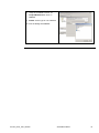
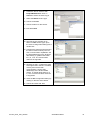
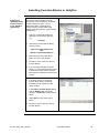
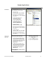
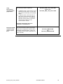
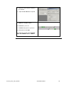
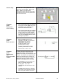
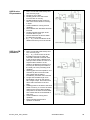
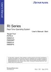
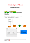
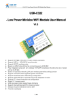
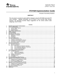
UDP and TCP Communication for Quantum and Premium PLCs running UnityPro Applications System User Guide 33004102.00 [source code] DEC 2006 Contents Application Source Code.......................................................................................................................5 Typical Applications...............................................................................................................................6 System ........................................................................................................................................................7 Architecture .........................................................................................................................................7 PLC and Ethernet Hardware Configuration ............................................................................................9 Configuration Software ........................................................................................................................ 10 Software Installation............................................................................................................................. 11 Implementation .................................................................................................................................14 Configuring the IPCom servi ces........................................................................................................... 14 Installing Function Blocks in UnityPro ................................................................................................. 18 Sample Applications .......................................................................................................................19 Operate Sample Application on the PLC .............................................................................................. 21 Understanding the Sample Application................................................................................................ 23 Appendix ..................................................................................................................................................28 Detailed Component List ...............................................................................................................28 Concept Version of IPCom ............................................................................................................29 Contact......................................................................................................................................................30 Introduction This document is intended to provide a quick introduction to the described System. It is not intended to replace any specific product documentation. On the co ntrary, it offers additional information to the product documentation, for installing, configuring and starting up the system. A detailed functional description or the specification for a specific user applic ation is not part of this document. Nevertheless, the document outlines some typical applications where the system might be implemented. IPCom_UDP _TCP_EN. doc Schneider Electric 2 Abbreviations Word / Expression Signification AC Advantys Alternating Current SE product name for a family of I/O modules Altivar (ATV ) CANopen CB CoDeSys ConneXium DC EDS E-OFF, E-STOP SE product name for a family of VSDs Name for a communications machine bus system Circuit Breaker Hardware-independent IE C 61131-3 programming software SE product name for a Family of Trans parent Factory devices Direct Current Electronic Data Sheet Emergency Off switch Harmony HMI I/O IclA (ICLA) Lexium/Lexium05/LXM Magelis MB - SL SE product name for a family of switches and indicators Human Machine Interface Input/Output SE product name for a compact drive SE product name for a family of servo-drives SE product name for a family of HMI-Devices SE name for a serial Modbus communications protocol Micro NIM Osi switch PC PDO Phaseo PLC Powersuite SE product name for a middle range family of PLCs SE product name for a Net work Interface Module SE product name for a family of position switches Personal Computer Process Data Object (CA Nopen) SE product name for a family of power supplies Programmable Logic Computer An SE software product for configuring drives Premium Preventa PS1131 (CoDeSys) PS RPDO SE SDO SE product name for a middle range family of PLCs SE product name for a family of safety devices SE Product name for PLC programming soft ware with CoDeSys Power Supply Receive Process Data Object (CA Nopen) Schneider Electric Service Data Object Sycon SE product name of a Field bus programming software IPCom_UDP _TCP_EN. doc Schneider Electric 3 Word / Expression Telefast Signification SE product name for a series of distributed I/O devices TesysU TPDO Twido TwidoSoft TwidoSuite Unity (P ro) Vijeo Designer VSD SE product name for a decentralised I/O System Transmit Process Data Object (CANopen) SE product name of a middle range family of PLCs SE product name for a PLC programming software SE product name for a PLC programming software SE product name for a PLC programming software An SE software product for programming Magelis HMI devices Variable Speed Drive WxHxD XBT-L1000 Zelio ZelioSoft Dimensions : Width, Height and Depth An SE software product for programming Magelis HMI devices SE product name for a low range PLC family SE product name for a PLC programming software IPCom_UDP _TCP_EN. doc Schneider Electric 4 Application Source Code Introduction Examples of the source code used to attain the system function as described in this document can be downloaded from our „Village“ website under thi s link. The example source code is in the form of configuration, application and import files. Use the appropriate software tool to either open or import the files. Extension File Type Software Tool Required AIW CNF CO CSV CTX DCF DIB DOC Configuration File Configuration File CANopen definitions file Comma Separat ed Values, Spreadsheet Device Configuration File Device Independent Bitmap Document file Advantys Sycon Sycon Twidosoft Unity Advantys Sycon Microsoft Word DOP EDS FEF GSD ISL PB PDF Project File Electronic Data Sheet – Device Definition Export file EDS file (Geraete Stamm Datei) Island file, project file Profibus definitions file Portable Doc ument Format - document Magelis XB TL Industrial standard PL7 Profibus Advantys Sycon Adobe Acrobat PRO PS2 RTF SPA STU STX TLX TWD Project File Export file Rich Text File - document Schneider Product Archive Project file Project file Project file Project file PS1131 - CoDeSys Powersuite export file Microsoft Word TwidoSuite Unity studio PL7 Twinline control tool TwidoSoft VDZ XEF XPR ZM2 Project file Export file Project file Project File Vijeo Designer Unity Pro TwidoSuite Zeliosoft IPCom_UDP _TCP_EN. doc Schneider Electric 5 Typical Applications Introduction Here you will find a list of the typical applications, and their mark et segments, where this system or subsystem can be applied: The IP Com communication library is intended for TCP or UDP communication bet ween Schneider Electric Quant um or Premium PLCs and non-Schneider Electric devices and controllers. The communication library is available on Quantum and Premium controllers running Unity and also on Quantum controllers running Concept. The present document only describes the Unity integration. For detailed documentation of the FactoryCast HMI configuration extension and a detailed communication function block description please consult the documentation delivered with the IP Com package. Application Steelworks Labeling Machine IPCom_UDP _TCP_EN. doc Description Image IPCom library used for communication to: - B&R HMI systems - Siemens PLCs IpCom library used for communication to: - Siemens Scada system - Siemens PLCs Schneider Electric 6 System Introduction The system chapter describes the architecture, the dimensions, the quantities and different types of components used within this system. Architecture General The IP Com communication capabilities are achieved using a collaboration of specific communication modules with specific firmware extensions and specific function block libraries for use in the applic ation programs running on the controllers. The maximum communication capacity for one communication module is: 16 TCP connections, bi-directional send and receive, maximum 1460 bytes per telegram, maximum 8000 Bytes altogether 16 UDP connections, unidirectional send or receive, maximum 2040 bytes per telegram, maximum 8000 Bytes altogether Components Hardware: In addition to the standard Unity PLC hardware, a FactoryCast HMI communication module is needed: for Quantum PLCs: 140 NWM 100 00 for Premium PLCs: TS X WMY 100 Software: In addition to the standard UnityPro installation, the following software and libraries are needed: FactoryCast HMI Configuration Software IPCom function block libraries for IP and TCP communication IMPORTANT FactoryCa st HMI communication module s used for IPCom Ethernet communication cannot be used for the standard FactoryCa st HMI service s. A module performing one or more standard FactoryCa st HMI service s cannot perform IPCom communication. Quantities of Components For a complete and det ailed list of components, the quantities required and the order numbers, please refer to the components list at the rear of this document. IPCom_UDP _TCP_EN. doc Schneider Electric 7 Degree of Protection Not all the components in this configuration are designed to withstand the same environmental conditions. Some components may need additional protection, in the form of housings, depending on the environment in which you intend to use them. For environment al details of the individual components pleas e refer to the list in the appendix of this document and the appropriate user manual. IPCom_UDP _TCP_EN. doc Schneider Electric 8 PLC and Ethernet Hardware Configuration General Quantum In addition to standard Quantum PLC hardware a dedicated Factory Cast HMI communication module 140 NWM 100 00 is required. Premium In addition to standard Quantum PLC hardware a dedicated Factory Cast HMI communication module TSX WMY 100 is required. Ethernet Network IPCom_UDP _TCP_EN. doc In addition to the Ethernet connection a dedicated Modbus or, respectively, Unitelway programming connection might be necessary. Schneider Electric 9 Configuration Software General The configuration and programming of a PLC with IPCom communication is done with UnityPro and FactoryCast HMI Configuration Software. The IP Com communication package does not need any additional Soft ware tools except that delivered with the IPCom package. To use the software packages, your P C must have the appropriate Microsoft Windows operating system installed: Windows 2000 or Windows XP. The soft ware tools are installed to the following default paths: UnityPro C:\Program Files\Schneider Electric\Unity Pro FactoryCast HMI C:\Program Files\Schneider Electric\Factory Cast HMI IPCom Configuration Software Manual installation – described below IPCom runtime soft ware Manual installation – described below Communication Function Blocks Manual installation – described below IPCom Documentation To date, the documentation for IP Com is only available in German. Copy the contents of the IP Com package to a temporary directory, e.g. “C:\Temp\” The IP Com documentation can be found at ..\Ipcom-vx.y\doc\ The doc-subdirectories contain the documentation files: konfig\ tcpcom\ udpcom\ IPCom_UDP _TCP_EN. doc Schneider Electric 10 Software Installation Preconditions Before continuing with the set up pleas e check that: Check Available Services UnityPro is properly installed.FactoryCast HMI configuration soft ware is properly installed. The communication modules are equipped wit h the appropriate firmwareThe PLC configuration, including the communications module IP configuration, is done. The communication module is setup with a clean Factory Cast HMI configuration (Module/Format the Module). The module is connected to the Ethernet network and running. 1. Start the FactoryCast HMI configuration soft ware. 2. Create a new configuration: Project/New/Project 3. Set Project Name, Module Type and Platform 4. Commit the project creation via Finish. The new project will be created, initialized and shown in the Navigator pane. 5. In the Navigator pane, click on the new project and select Properties via the context menu. 6. Set the IP-Addre ss of the module inside the dialog. 7. Commit with OK. IPCom_UDP _TCP_EN. doc Schneider Electric 11 8. Verify the available services via Project/New/Service. click on Choose. 9. There will be no IP Com service type available. 10. Exit the dialogs with Cancel Install IPCom configuration plugin into FactoryCast HMI Configuration software 1. Close the FactoryCast HMI configuration software 2. and go to the Microsoft explorer. 3. Copy the contents of the IP Com package to a temporary directory, e.g. C:\Temp\ 4. Find the IPCom configuration plug-in at ..\Ipcom-vx.y\java\ui\ 5. Find the plug-in installation path of FactoryCast HMI at C:\Program Files\Schneider Electric\Factory Ca st HMI\plugins\ 6. Drag the cont ents of the ..\ui-directory to the ..\plugins-directory. 7. Start FactoryCast Configuration software. IPCom_UDP _TCP_EN. doc Schneider Electric 12 8. Verify the available services via Project/New/Service. Click on Choose. 9. IPCom service type is now available. 10. Exit the dialogs with Cancel. IPCom_UDP _TCP_EN. doc Schneider Electric 13 Implementation Introduction The implementation chapter describes all the steps necessary to initialise, to configure, to program and start-up the system to achieve the application functions as listed below. Configuring the IPCom services IPCom Configuration in Factory Ca st 1. Start FactoryCast HMI configuration software. 2. Create a new configuration: Project/New/Project 3. Set Project Name, Module Type and Platform 4. Commit the project creation wit h Finish. The new project will be created, initialized and shown in the Navigator pane. 5. In the Navigator pane click on the new project and select Properties via the context menu. 6. Set the IP-Addre ss of the module inside the dialog. 7. Commit it with OK. IPCom_UDP _TCP_EN. doc Schneider Electric 14 8. Create the IPCom services with Project/New/Service. Click on Choose to select the servic e type. 9. Select the IPCom service type. 10. Commit it with OK. 11. Choose a Name for the service. 12. Exit with Finish. 13. The new service appears as an element of IPC service type. Open the servic e configuration dialog with a double click. 14. Configure the data exchange areas in the PLC’s located memory area for TCP communication capabilities. Set the start address(es) of the 80 Word data area(s). A gradual reservation for 4, 8, 12 or 16 communication channels is supported. 15. Similarly for UDP, configure the data exchange areas in the PLC’s located memory area for the UDP communication. Set the start address(es) of the 80 Word data area(s). A gradual reservation for 4, 8, 12 or 16 communication channels is supported. 16. Close the IPC configuration dialog by clicking on the tab's close button. 17. Commit and save with Ye s. IPCom_UDP _TCP_EN. doc Schneider Electric 15 Install IPCom servi ce on the FactoryCa st HMI module 1. Copy the contents of the IP Com package to a temporary directory, e.g. C:\Temp\ 2. Find the IPCom runtime soft ware at ..\Ipcom-vx.y\java\service s\ 3. The runtime software is in the file ipcom.jar 4. Find the service installation pat h on the FactoryCast HMI communication module in the FactoryCast HMI configuration tool on the Navigator pane. 5. The ipcom-service has to be located directly in the root path of the project, parallel to the Namespace Write Access file. 6. Drag the ipcom.jar file from the ..\service s-directory on the PC hard disk to the project-path inside the Navigator. 7. Download the service ont o the FactoryCast HMI module. This has to be done explicitly. For this, select the ipcom.jar file inside the Navigator and do: Partial Transfer / PC -> Module from the cont ext menu. Transfer the configuration to the communication module 8. You will be asked to reboot the module after download. Confirm wit h YES. 1. Trans fer the complete configuration to the communication module. On the context menu of your FactoryCast HMI project select: Global Transfer->P C -> Module IPCom_UDP _TCP_EN. doc Schneider Electric 16 2. You will be reminded again that a module reboot is needed. Confirm the reboot with YES. 3. After the reboot the module is ready to operate the communication services requested from the application Program. You can now close or minimize the FactoryCast HMI. IPCom_UDP _TCP_EN. doc Schneider Electric 17 Installing Function Blocks in UnityPro Installing or updating IPCom function blocks in the UnityPro application The IP Com communication function blocks have to be installed in an already created UnityPro project, see the description below. (Alternatively a Custom Library can be created and added to UnityPro with the Types Library Update tool.) 1. Copy the contents of the IP Com package to a temporary directory, e.g. C:\Temp\ 2. The IP Com function blocks library can be found in: ..\Ipcom-vx.y\fb\unity\tcpcom\ and ..\Ipcom-vx.y\fb\unity\udpcom.\ 3. Install the IPCom function block library into your Unity project. 4. Do this for each of the four IPCom function blocks. 5. If you load the complete example project, no extra function block import is necessary as the IPCom function block library is already included in this project. 6. If an older version of the IPCom function block library is already installed you can update it to the newer version. 7. In the Import Trouble Report dialog click on Replace All. All checks appear in the Replace column of the dialog. 8. Select OK to import the function block. 9. Do this for each of the four IPCom function blocks. IPCom_UDP _TCP_EN. doc Schneider Electric 18 Sample Applications Introduction Unity Server project file The SampleProjects subdirectory of the IPCom distribution contains 8 files: 1. Unity export file Premium_UDP_TCP_Client.XEF. 2. The same as 1 but without a PLC rack configuration for easy adaptation to any PLC. 3. A FactoryCast HMI module configuration export file Premium_WMY100. ZIP. 4. A FactoryCast HMI module configuration export file Quantum_NWM10000. ZIP. 5. A Unity export file Quantum_Te stserver.XEF. 6. The same as 5 but without the PLC rack configuration for easy adaptation to any PLC. 7. A Unity export file Quantum_UDP _TCP _Server.XEF. 8. The same as 7 but without a PLC rack configuration for easy adaptation to any PLC. The example project implements: 1. A TCP server on port 2002. The server immediately returns the data extracted from the received request to the responding client. This can be tested with the PC application tcpclient.exe. 2. A UDP server on port 2001. The server immediately returns the data extracted from received request to the responding client. This can be tested with the PC application udpclient.exe. Quantum_Te stserver.XEF together with PC applic ation tcpclient.exe and PC applic ation udpclient.exe It is thi s application example which is described below. IPCom_UDP _TCP_EN. doc Schneider Electric 19 Unity Peer-to-Peer communication project files The example projects implement: 1. 2. A Quantum with a TCP server on port 2002 and a UDP server on port 2001 with similar functionality as described above. A Premium with a TCP client and a UDP client communicating with the Quantum server PLC. An additional Operator Screen allows convenient control and monitoring of the communication clients. Premium_UDP_TCP_Client.XEF together with Quantum_UDP _TCP _Server.XEF No further description for the se examples i s included here. FactoryCa st HMI module configuration export files The communication module export files contain the configuration us ed for all the examples mentioned above. These are not needed if the module configuration is done manually. IPCom_UDP _TCP_EN. doc Premium_WMY100. ZIP and Quantum_NWM10000. ZIP Schneider Electric 20 Operate Sample Application on the PLC Operate sample application 1. Launch UnityPro on your PC. 2. Open the sample application Quantum_Testserver. XEF. Before locating the project file in your file system, select the appropriate file type .X EF. 3. Click on Open once the file is selected. 4. If your PLC configuration is not similar to the PLC configuration in the sample project, it might be better to configure part of the application manually to fit your PLC. To do this open the sample application: Quantum_TestserverwithoutConf.XEF. You are asked to select a PLC. The application is a Quantum application so you have to select an appropriate Quantum PLC. 5. Complete the rack configuration. Adjust the backplane size and add at least a power supply and the communication module 140 NMW 100 00. 6. Adjust the State Ram memory usage to 40000 words. IPCom_UDP _TCP_EN. doc Schneider Electric 21 7. Link the communication module to the network. 8. Adjust the IP address as required. 9. Build the complete project. 10. Connect to your PLC. 11. Transfer the project to your PLC. 12. Start the PLC wit h Run. The status bar should indicate EQUAL, RUN, UPLOADINFO OK and BUILD. IPCom_UDP _TCP_EN. doc Schneider Electric 22 Understanding the Sample Application Application program main parts Section Tcp Opening the sample project creates all relevant objects for the application. The UnityPro Project Brow ser displays these objects: The entry Derived Data Types contains the dat a type definitions used for variables intended to accomplish the access to the communication channels. The entry Derived FB Type s contains the definitions for the 4 function blocks managing the communication data exchange. These DFBs use the data types defined in the node above. The entry Program contains the two FBD sections of the application program. The section Tcp implements the TCP server function, the section Udp implements the UDP server function. The TCP server is implemented in the function block TCP C_SERVE R. The logic blocks connected are concerned with the startup and error recovery behaviour of the function block. IPCom_UDP _TCP_EN. doc Schneider Electric 23 Section Udp The UDP server is implement ed in the two function blocks UDPC_RE CV and UDP C_SE ND. The logic blocks connected to theses are concerned with the startup and error rec overy behaviour of the function blocks. Common parts: The communication FBs are disabled during the cold start (%S0) and warm start (%S1) scans. Enabling aft er these scans restarts the FBs. The communication FBs are disabled when det ecting errors (Error output). As long as the error exists the FBs are disabled but enabled periodically every second (%S 6) until they can restart regular operation. Error and Stat indicate errors detected by the FB. This could be a configuration error (wrong configuration of IPCom on FactoryCast HMI, wrong parameterization of FB, communication problems during operation). Identified errors are specified with an error code. Startup and error recovery Common parts: Fault indication Common parts: Collaboration with FactoryCa st HMI module As seen during the FactoryCast HMI configuration before, each module is capable of executing 16 TCP and 16 UDP services. The services are organized into maximum channels with 4 services on each channel. One channel is capable of executing one type of service, mixing services is not supported on channels. The IPCOM In-Out -parameter must point to a variable of data type IPCOM_B UF. This is the management dat a structure for one channel. The Path parameter has to address one of the 4 communication services. This is the path inside the channel. IPCom_UDP _TCP_EN. doc Schneider Electric 24 TCP Server FB parameters Test of section Tcp S vrPort is set to 2002. Run and Close are connected to the startup and error recovery logic. SndReg and Rc vReg are set to the same register address. This ensures that the received data is immediately available for the response. SndLen is set according to the lengt h of the received data indicated on Rc vLen. Snd is triggered from Rc v when a request is received. Rc vMax determines the maximum size of the receive buffer in memory in bytes. Activity indicates a running transaction (request, response). Connected indicates that a client has connected to the server. The IPaddress (IP _1 .. IP_4) and send port (Port) of the client are indicated. SndDone indicates that the response is finished. Rc vTime indicates the time at which the request was received. To test of the TCP server function, the command line tool tcpclient.exe is used. 1. Copy the contents of the IP Com package to a temporary directory, e.g. C:\Temp\ 2. Find the TCP test client at ..\Ipcom-vx.y\tools\ The test client requires at least three parameters: The IP-address of the TCP-server on the PLC/communication module. The port on which the server listens. The repetition rate. Invocation of the tool wit hout parameters produces a short help information. IPCom_UDP _TCP_EN. doc Schneider Electric 25 UDP Receive FB parameters UDP Send FB parameters Run is connected to the startup and error recovery logic. Rc vPort is set to 2001. Rc vReg points to the start of the receive buffer in memory. Rc vMax determines the maximum size of the receive buffer in memory in bytes. Active indicates a running receive operation. Ndr indicates that valid dat a has been received. Length indicates the length of the received data in bytes. RxTime indic ates the time at which the data was received. IP_1 .. IP_4 and Port indicat e the IP address and send port of the sender. Run is connected to the startup and error recovery logic. IP_1 .. IP_4 and Port are set to the IP-address and port to which the send FB is ordered to trans fer data. In this example the IP -address and send port from sender are used. It is expected that a listener on the sender’s IP-address is listening on a receive port with the port number of the send port of the preceding send operation. Send triggers the send operation. It is activated by the receive FB’s Ndr. This means that the data is immediat ely sent back after received. Length sets the data length to be transmitted. It is set by the receive FB’s Length output. This means that all the data received is to be sent back. SndReg points to the start of the send buffer in memory. It is set to the same values as the receive FB’s Rc vReg and points to the same receive buffer. This means that the received data is sent back. Active indicates a running send operation. Done indicat es that the send operation is finished. IPCom_UDP _TCP_EN. doc Schneider Electric 26 Test of section Udp To test the UDP server function the command line tool udpclient.exe is used. 1. Copy the contents of the IP Com package to a temporary directory, e.g. C:\Temp\ 2. Find the UDP test client at ..\Ipcom-vx.y\tools\ The test client requires at least three parameters: The IP-address of the UDP-server on the PLC/communication module. The port on which the server listens. A repetition rate. Invocation of the tool wit hout parameters gives a short help information. IPCom_UDP _TCP_EN. doc Schneider Electric 27 Appendix Detailed Component List Additional Hardware-Components Pos. Amt. 1 Description Part Number Rev./ Vers. Ethernet communication module for Quantum PLCs 140 NWM 100 00 140 NWM 100 00 or 2 Ethernet communication module for Premium PLCs TS X WMY 100 TS X WMY 100 Additional Software-Components Pos. Amt. Description 1 FactoryCast HMI Configuration Software 2 IPComm function block libraries for UDP and TCP communication IPCom_UDP _TCP_EN. doc Part Number Rev./ Vers. TLX CD FCHMI V1M V1.2 Schneider Electric 28 Concept Version of IPCom Concept For Concept systems with Quantum PLCs the IP Com TCP and UDP communication is also available. The required Ethernet communication module 140 NWM 100 00 is applied as described above. For the Conc ept application program a set of similar Concept function blocks is available. IPCom_UDP _TCP_EN. doc Schneider Electric 29 Contact Author Schneider Electric GmbH CMachines and Process Architectures Schneider Electric GmbH Steinheimer Strasse 117 D - 63500 Seligenstadt Germany IPCom_UDP _TCP_EN. doc Telephone E-Mail +49 6182 81 2555 [email protected] As standards, specifications and designs change from time to time, please ask for confirmation of the information given in this publication 30