1
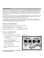
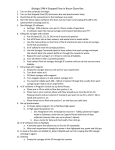
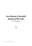
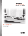
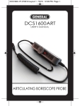
No. 870
USER’S MANUAL
(U.S. PATENTS APPLIED FOR)
PLEASE READ THESE INSTRUCTIONS FULLY BEFORE USING THIS JIG
www.generaltools.com/woodworking
CONTENTS
Introduction . . . . . . . . . . . . . . . . . . . . . . . . . . . . . . . . . . . . . . . . . . . . . . . . . . 3
Capacity and Specifications . . . . . . . . . . . . . . . . . . . . . . . . . 3
What’s in the Jig Kit . . . . . . . . . . . . . . . . . . . . . . . . . . . . . . . . 3
Anatomy of the Jig . . . . . . . . . . . . . . . . . . . . . . . . . . . . . . . . . . . . . . . . . . . . . 4
Anatomy of the “Quick Change” Router Base Bushing Assembly . . . . . . 4
Preparing the Router . . . . . . . . . . . . . . . . . . . . . . . . . . . . . . . . . . . . . . . . 5 – 6
Safety Overview . . . . . . . . . . . . . . . . . . . . . . . . . . . . . . . . . . . 5
Installing the “Quick Change” Guide Sleeve . . . . . . . . . . . . 5
Centering the Base Plate and the
“Quick Change Guide System” . . . . . . . . . . . . . . . . . . . . . . . 5
Setting the Cutting Depth . . . . . . . . . . . . . . . . . . . . . . . . . . . 6
Mounting the Jig . . . . . . . . . . . . . . . . . . . . . . . . . . . . . . . . . . . . . . . . . . . . . . 6
Operating Instructions . . . . . . . . . . . . . . . . . . . . . . . . . . . . . . . . . . . . . 7 – 12
1. Marking Joint Centers and Location . . . . . . . . . . . . . . . . 7
2. Centering the Stock . . . . . . . . . . . . . . . . . . . . . . . . . . . . . . 7
3. Positioning the Stock using the Positioning Bars . . . . . . 8
4. Setting the Joint Length . . . . . . . . . . . . . . . . . . . . . . . . . . . 9
Length of Mortise & Tenon Chart . . . . . . . . . . . . . . . . . . . 9
5. Setting the Depth of the Router Bit . . . . . . . . . . . . . . . . . 10
6. Routing the Tenon . . . . . . . . . . . . . . . . . . . . . . . . . . . . . . . 11
7. Routing the Mortise . . . . . . . . . . . . . . . . . . . . . . . . . . . . . 12
Routing Other Size Mortise and Tenons . . . . . . . . . . . . . . . . . . . . . . . . . . 13
Customer Support . . . . . . . . . . . . . . . . . . . . . . . . . . . . . . . . . . . . . . . . . . . . 14
Warranty Information . . . . . . . . . . . . . . . . . . . . . . . . . . . . . . . . . . . . . . . . . 14
Notes . . . . . . . . . . . . . . . . . . . . . . . . . . . . . . . . . . . . . . . . . . . . . . . . . . . . . . . 15
Sample Mortise &
Tenon Joint
2
INTRODUCTION
Thank you for purchasing General Tools & Instruments’ E-Z ™ Pro Combination Mortise & Tenon
Jig (M&T Jig)— the woodworking industry’s first integrated jig capable of making matching mortise
and tenon joints of professional quality “right out of the box.” The jig makes creating Mortise &
Tenon joints—the sturdiest of all wood joints—for furniture, cabinets and frames – an easy, simple,
and fast process.
The Mortise & Tenon Kit comes with a fully assembled jig and includes a 1/4" straight up-cut router
bit and 1/4" guide bushing. Also included are the guide bushings for cutting 3/8" and 1/2" joints.
You will need to supply your own 3/8" and 1/2" upcut router bits.
The M&T Jig has a one-piece heat treated, high grade aluminum body, with its adjusting bolts,
up-cut fasteners and bit made of steel to SAE specifications. The unit’s adjustable positioning bars
and router bushing assembly are also made of solid steel.
Capacity and Specifications:
Accommodates stock from 1/2" to 1½" thick and any length
Mortise and Tenon thickness: 1/4", 3/8" and 1/2"
Minimum length M&T Joint: 1" +/- 1/8" (depending on bit used)
Maximum Length M&T Joint: 3" +/- 1/8" (depending on bit used)
What’s in the M&T Jig Kit
1. The fully assembled jig
2. “Quick Change” Router Base Bushing Assembly consists of:
• One “Quick Change” 1-3/16" guide sleeve
and locking nut
1
• One 1/4" guide bushing (1-1/4" OD)
• One 1/4" shank centering pin
• One flat spanner wrench for guide sleeve
locking nut adjustment
• One 3/8" guide bushing
2
• One 1/2" guide bushing
3. One 1/4" straight upcut spiral carbide
router bit
3
It is highly recommended that you familiarize yourself with the nomenclature in Fig. 1 and Fig. 2
on p. 4 before proceeding.
3
ANATOMY OF THE E-Z PRO MORTISE & TENON JIG
Fig. 1
JIG ASSEMBLY IN PROFILE
4C
JIG ASSEMBLY
MORTISE SECTION
1 - Jig Assembly
1A - Centering Marks
TENON SECTION
5 - Face Clamp Thumb Screws
6 - Positioning Bars
1B - Centering Notches
6A - Positioning Bars deployed
1C - Template Positioning Indicators
6B - Positioning Bars retracted for storage
and cutting
2 - Mortise Section Templates
2B - Template Position Rule
3 - Tenon Section Templates
7 - Face Clamps
8 - Mounting Flange
4 - Centering Wall, [4A] Markings,
[4B] Serrations, [4C] Thumb Screws
ANATOMY OF THE “QUICK CHANGE” ROUTER BASE
BUSHING ASSEMBLY:
Fig. 2
R1 - Lock Nut
R5 - Flat Spanner Wrench
R2 - 1-3/16" Router Base Guide Sleeve
R6 - 7/8" O.D. Router Guide Bushing
for the 3/8" Tenon
R3 - 1-1/8" O.D. Router Guide Bushing for
the 1/4" Tenon (as well as for all
mortises)
R4 - Centering Pin
4
R7 - 5/8" O.D. Router Guide Bushing
for the 1/2" Tenon
R8 - 1/4" Upcut Routing Bit
PREPARING THE ROUTER
SAFETY OVERVIEW
1. KNOW YOUR ROUTER. Read the owner’s manual that came with your router before you use it.
Understand the machine’s applications and limitations, as well as the specific potential hazards
inherent in its use. Before using the router, check that none of its moving parts is broken, loose
or misaligned.
NOTE: General Tools & Instruments is not responsible for router misuse or the disregard of
standard safety precautions associated with using a router.
Installing the “Quick Change”
guide sleeve
The E•Z Pro M&T Jig is designed to be used with
plunge routers with base plates with a 1-3/16"
center hole and a 1-3/8" counter-bore. This is to
accommodate the included “Quick Change”
guide sleeve and bushing. If your router base
cannot mate with the guide sleeve, you can
purchase a “Universal Router Plate” with the
appropriate center hole dimensions to attach
to or replace your current router base.
With the proper base plate installed,
1. Insert the Guide Sleeve [R-2] into the Base
Plate.
2. Secure the Lock Nut [R-1] firmly with
the flat Spanner Wrench Provided.
3. Screw the 1-1/8" Router Guide Bushing [R-3]
into the center of the guide sleeve and hand
tighten. (Fig. 3)
Fig. 3
BASE PLATE WITH
1-3/16" CENTER
HOLE AND A
1-3/8" COUNTER
Fig. 4
Centering the Base Plate and
the “Quick Change Guide System”
1. With your router upside down, plunge the base
and lock it.
2. Insert the 1/4" Centering Pin [R-4] in the router
chuck and tighten it securely.
3. Loosen the mounting screws of the base plate
just enough to allow a little movement.
(Fig. 4)
4. Carefully release the plunge lock and gently
guide the plunge base to extension on the cone
section of the centering pin; (Fig. 5) this allows
the loosened base plate to move on its screw
holes to a perfect centering position.
Fig. 5
5. Tighten the base plate screws securely.
5
Fig. 6
• Once you have completed this centering
operation, remove the centering pin from the
router and replace it with the router bit.
Setting the Cutting Depth
• Set the depth of your plunge router for the desired depth of your mortise and tenon.
• When the stock is correctly mounted in the jig, its top edge will be 1/2" below the top (working)
surface of the jig (Fig.7a).
• Accordingly, add 1/2" to the desired depth of the mortise and tenon when setting the “plunge”
depth of the router (Fig.7b).
Fig. 7A
POSITIONING ARM
SHOWN DEPLOYED
FROM THE FACE
OF THE BASE
PLATE TO THE
TIP OF THE
CUTTING BIT
EQUALS THE
DEPTH OF THE
JOINT PLUS 1/2"
Fig. 7B
ROUTER IN THE FULLY
PLUNGED POSITION
MOUNTING THE JIG
The M&T Jig can be mounted directly on the edge of a bench using the integral mounting flange [9]
(Fig. 8A), or secured to a mounting board which can then be clamped to a bench (Fig. 8B).
WORK BENCH
Fig. 8A
6
WORK BENCH
Fig. 8B
OPERATING INSTRUCTIONS:
1. Marking Joint Centers and Location
Mark the stock with center marks at the positions for the tenon and the mortise. These marks will
be needed to center the tenon section and the longitudinal position of the mortise on the stock. If
you have correctly set the centering wall for the thickness of the stock, the stock will automatically
be centered** for stock thickness when clamped in the jig.
**Tip: if there is a variation in the thickness of the stock used, you may adjust for this by use of
appropriate shims or by readjusting the centering bar.
CENTER POSITION OF THE TENON
CENTER POSITION OF THE MORTISE
Fig. 9
TENON SECTION
MORTISE SECTION
2. Centering the Stock
• Centering the stock in the jig is
accomplished by adjusting the
centering wall [4] (Fig.10) for
the thickness of the stock.
• The jig will handle stock with
a thickness between 1/2" and
1-1/2".
• Using the lumber industry’s
nomenclature, these two
thicknesses, designated as,
“2 quarter” (1/2") and
“6 quarter” (1-1/2"), indicating
the number of 1/4" increments of thickness.
Fig. 10
• The markings are on the tenon end of the Centering Wall [4A]. Use these “quarter” units to adjust
for the thickness of your stock in “quarters”. For example: if you are using 3/4" (three quarter)
stock, align the number “3” with the inner wall of the jig (Fig. 11), and the stock will be at its
nominal center in the templates.
• When adjusting the Centering Wall, and to maintain parallel
alignment, always make sure the bar is correctly seated
on the jib body with its serrated matching surface
[4B] (Fig.11) in the jig.
Tips: to assure an accurate joint
alignment, particularly if you are making
a face frame or similar matching
surface type joint, always keep the
matching faces to the same side of the jig.
Fig. 11
7
3. Positioning the Stock Using the Positioning Bars
When in the deployed position (Fig 12), the Positioning Bars serve two basic purposes:
1. They position the stock at the correct depth below the underside of the template for routing
2. They align the stock so it is squared, at 90 degrees, to the jig longitudinally
6A
Fig. 13
Fig. 12
The Positioning Bars [Fig 12 and 13] are stored along
the inside edge of the underside of the jig’s top when
routing.
1. To extend the bars, use the Positioning Bar handles
[6A], located under the outside top edge.
Fig. 14
2. After you fully deploy the Positioning Bars, you’re
ready to place the stock in the jig. Insert the stock
gently up against the deployed Positioning Bars
(Fig. 14) and tighten the Thumb Screws [5] just
enough so the stock is held loosely by the Face
Clamps [7].
3. Center the stock longitudinally using the jig’s centering marks [1A] on the jig (Fig. 15). Before
tightening the Face Clamps, be sure the stock is flat and square against the Positioning Bars
(but not too tight) and correctly centered.
4. Tighten the Face Clamps, enough to secure the stock from moving.
5. Using their handles, return the Positioning Bars to their storage position (Fig15).
IN USE POSITION
Fig. 15
8
STORED FOR ROUTING
4. Setting the Joint Length
The M&T jig has two working sections, the mortise section and the tenon section (Fig. 16).
Fig. 16
2
2
2B
2
2
2B
1C
TENON SECTION
MORTISE SECTION
Each section is equipped with left and right Adjustable Sliding Templates [#2] (Fig.16) that are used
to set the length of the cut. There are 0, 1/2 and 1 marks alongside each template’s edge [2B].
When you set the size of the opening, make sure that ALL of the templates indicate the same
measurement; this assures that the cut will be centered. (Fig. 16)
To adjust the templates for the desired joint length, loosen the Lock Screws on the right and left
template and slide them to the desired equal position (as indicated with the Template Positioning
Rules [2B]), and re-tighten the screws.
When the “0” on the template positioning rule [2B] is aligned with the Template Position
Indicator [1C] on the jig surface, the template is open to its longest position and approximates a 3"
long joint** (Fig. 16).
When the “1” is aligned with the template position indicator [1C], the template is closed to its
shortest position and approximates a 1" joint**.
These are actually fractional inch markings and refer to the amount of template closure. For
example, if you set the templates to 1/2 it means that you’re reducing the (approx**) 3" long joint
by a 1/2" on each side. Therefore your joint size will be (approx**) 2". Or, if you set the template to
3/4 you’ll be taking 3/4" from each side of the joint resulting in a joint length of (approx**) 1-1/2".
Please note: the chart below indicates the exact length of each joint for each marking on the
template and for each bit size.
Make the same ruler settings to both templates on the mortise side as well as to both sides of the
tenon side to have a centered and matching mortise and tenon. (Fig. 18)
** For exact joint lengths for each size bit, please refer to the sizing chart below
Length of Mortise and Tenon Chart
Template Position Markings
Joint
Thickness
0
1/8
1/4
3/8
1/2
5/8
3/4
7/8
1
1/4
2-7/8
2-5/8
2-3/8
2-1/8
1-7/8
1-5/8
1-3/8
1-1/8
7/8
3/8
3
2-3/4
2-1/2
2-1/4
2
1-3/4
1-1/2
1-1/4
1
1/2
3-1/8
2-7/8
2-5/8
2-3/8
2-1/8
1-7/8
1-5/8
1-3/8
1-1/8
9
The jig itself has two Centering Marks [1A] (Fig. 17) on its top surface that which indicate the
longitudinal center of the templates. There are also Centering Notches [1B] on the deployed
Positioning Bars [6]; they indicate the center of the template’s width. To keep the joint centered
longitudinally, always make the same template position setting to all templates.
Fig. 17
5. Set the Depth of the Router Bit (See also “Setting the Cutting Depth” on page 6)
To set the “plunge” depth of the router (Fig. 18) and subsequently the cutting depth of the bit,
remember to add 1/2" to the desired depth of the joint. Therefore, if you’re setting the joint depth
to be 1" then your measurement would be a total of 1-1/2" from the face of the base plate to the
tip of the bit.
FROM THE FACE
OF THE BASE
PLATE TO THE
TIP OF THE
CUTTING BIT
EQUALS THE
DEPTH OF THE
JOINT PLUS 1/2"
Fig. 18
10
Fig. 19
6. Routing the Tenon
When routing the tenon, make sure the
Guide Bushing [R-3] only rides against
the outer edges of the tenon template
[3] (Fig. 19) at all times.
1. Start the cut by putting the guide
bushing into the end of the template.
1/4" UP
CUT BIT
SHOWN
R-3 GUIDE
BUSHING
3
2. With the guide bushing in the end of
the template and the router base
squarely on the jig surface, turn the
router on.
3. Plunge the router to a workable depth
and guide the router bit clockwise
through the cutting process making
sure to keep the Guide Bushing tight
to the outer edge at all times.
NOTE: You can make successive
plunges to any depth while moving the
Guide Bushing clockwise around the
tenon template always riding against
the edge to make the cleanest joint
possible. We recommend making
successive shallow plunges and cutting
sweeps to avoid over stressing the
cutting bit. (Fig. 19 & 20)
Fig. 20
Caution: before retracting the router bit
from the cut, be sure to turn the router
off.
Tip: depending on the actual thickness
of your stock, you may at times get a
“fence” or “flash” around the edge of
your tenon (Fig 21). Be sure to cut, file or
sand it off cleanly to ensure a tight fit.
Fig. 21
11
2
Fig. 22
7. Routing the Mortise
Tip: when routing the mortise, it is advisable to increase the depth of cut slightly more than that of
the tenon to allow space for glue to be put on the tenon before inserting it into the mortise.
The Guide Bushing [R-3] fits the Mortise Template [2] (Fig. 22) exactly to prevent it from wandering
out of line. It will be used for all mortises regardless of size.
Fig. 23
1. Before turning on the router, place the guide bushing in the end of the mortise template and
slide it through the template to be sure it moves freely. (Fig. 23)
2. With the guide bushing in the end of the template and the router base squarely on the jig
surface, turn the router on.
3. Plunge the router and guide the router bit through the cutting process.
NOTE: We recommend cutting the mortise in successive overlapping plunges to depth and
then repeatedly move the bit back and forth to clean up the mortise slot. The method
you use is up to your experience on how to obtain the best cut.
12
ROUTING OTHER SIZE MORTISE AND TENONS
The E•Z Pro Mortise and Tenon Jig Kit includes the guide sleeve with Locking Nut [R2, R1], a
1-1/8" Router Guide Bushing for 1/4" joints [R3], a 1/4" Upcut Spiral Router Bit and a Centering
Pin [R4]. These parts will permit you to make 1/4" mortises and tenons suitable for 3/4" thick board
(Fig 24). The kit also includes the Guide Bushings you will need to make mortises and tenons of
1/2" [R7] or 3/8" [R6] (Page 4), however, you will need to make a separate purchase of the
corresponding upcut spiral bits. Please see sizing chart on Page 10.
• To make a 3/8" tenon, you’ll need a 3/8" Upcut Spiral Bit and the 7/8" Guide Bushing [R6].
• To make the matching 3/8" mortise, change to the 1-1/8" Guide Sleeve [R-3]. (Fig. 25)
• To make a 1/2" tenon, you’ll need a 1/2" Upcut Spiral Bit and the 5/8" Guide Bushing [R7].
• To make the matching 1/2" mortise, change to the 1-1/8" Guide Sleeve [R-3]. (Fig. 26)
NOTE: Guide bushings can be changed without removing router bit.
Fig. 24
1/4" JOINT
(shown on
1" stock)
MORTISE
TENON
MORTISE
TENON
Fig. 25
3/8" JOINT
(shown on
1-1/4" stock)
Fig. 26
1/2" JOINT
(shown on
2" stock)
MORTISE
TENON
13
CUSTOMER SUPPORT
Please visit our website at www.generaltools.com/woodworking to obtain additional woodworking
information, instructional videos and product manual.
http://www.generaltools.com/Products/E-Z-Pro-Mortise-and-Tenon-Jig__870.aspx
WARRANTY INFORMATION
The No. 870 Mortise & Tenon Jig Kit from General Tools & Instruments is warranted to the
original purchaser to be free from defects in material and workmanship for a period of one year.
Subject to certain restrictions, General will repair or replace this product, if, after examination,
it is determined by General to be defective in material or workmanship.
14
NOTES
_______________________________________________________________________
_______________________________________________________________________
_______________________________________________________________________
_______________________________________________________________________
_______________________________________________________________________
_______________________________________________________________________
_______________________________________________________________________
_______________________________________________________________________
_______________________________________________________________________
_______________________________________________________________________
_______________________________________________________________________
_______________________________________________________________________
_______________________________________________________________________
_______________________________________________________________________
_______________________________________________________________________
_______________________________________________________________________
_______________________________________________________________________
_______________________________________________________________________
_______________________________________________________________________
_______________________________________________________________________
15
GENERAL TOOLS & INSTRUMENTS
80 White Street, New York, NY 10013-3567
PHONE (212) 431-6100
FAX (212) 431-6499
TOLL FREE (800) 697-8665
e-mail: [email protected]
www.generaltools.com
870 User’s Manual
Specifications subject to change without notice
©2011 GENERAL TOOLS & INSTRUMENTS
NOTICE - WE ARE NOT RESPONSIBLE FOR TYPOGRAPHICAL ERRORS.
MAN#870 3/22/11