1
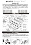
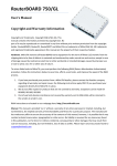
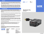
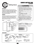
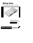
 FS‐PD1001‐E10 Specification Overviews FS‐PD1001‐E10 is a kind of PD Splitter (also called POE Splitter), supports IEEE802.3af standard; supplies power and transmits data to devices which do not support POE power supply (such as IP camera); The product uses the transformer for isolation design, which gives you more stable, more secure and Well‐protects the powered products ,Bandwidth is 10/100M. Mid‐Span (No.4&5and 7&8 cables supply power) and End‐Span (No.1&2 and 3&6 cables supply power) connections are well supported. Output voltage is 12V, maximum current is 1.08A. Some HD digital cameras do not have POE module which leads to the inconvenience and difficulty on installation. However, this device can solve the problem of wiring. Connect POE switch with PD Splitter, people can realize the power supply and data transmission of IP camera directly and timely. Typical applications please refer to following picture Features 1、Bandwidth: 10/100M 2、Input Voltage: 37‐57V 3、Input port: Supports (No.4&5 and 7&8 cables supply power) and End‐Span (No.1&2 and 3&6 cables supply power) connections. 4、Output Voltage: 12V 5、Output current: 1.08A (Max) 6、Standard: Supports IEEE802.3af 7、Isolation protection: Using the transformer for isolation design, more stable, more secure 8、Protection function: Overheating protection, Short circuit protection, overvoltage and overload protection Panel schematic diagram Front view
Back view Bottom view Installation steps 1. Before installation, please check the following equipments and accessories, if there are any missing, please contact with your supplier. 1). 1pc FS‐PD1001‐E10device 2). 1pc user manual 2. Please install as below steps 1) Before installation, please turn off the power of all signal sources and the monitor in case of the damage to transmission device. 2) Use network cables to connect PoE power supply device and RJ45 port of PD splitter 3) Connect DC connectors and RJ45 port with right powered device. 4) Check weather installation is correct and the device undamaged. Before power on PoE device, make sure that all connections are reliable. Technical Specification Features Standard Support IEEE802.3af Power supply mode Support Mid‐span and End‐span PoE Input Voltage 37‐57V DC Voltage Output 12V DC Current Output 1.08A(max) Output Power 12.96W Port and Performance Electrical interface parameters One input RJ45 port One Output RJ45 Plug One Power supply output DC Plug Cable Type Cat5 UTP and above Protocol Standards IEEE 802.3i 10BASE‐T IEEE 802.3u 100BASE‐T IEEE 802.3af Power over Ethernet Bandwidth 10/100M LED indicator lights POE input power supply indicator light DC output power supply indicator light Dimension 80*30*24.5mm(L*W*H) Weight(KG) Environment temperature Note: If any changes with product specification, forgive without prior notice 0.05kg Work temperature:‐5~45℃; Work Humidity:90%,No condensation Storage temperature:‐20~70℃;Storage humidity:95%,No condensation; Troubleshooting Such as equipment malfunction, according to the following way 1) Confirm whether equipment is installed as the manufacturer's installation requirements; 2) Confirm whether RJ45 cable contacted well, make sure no break, whether line order production complies with the EIA/TIA568A or 568B international standards; 3) Confirm the working power of device is less than PD Splitter’s max output power 12W. 4) Confirm whether PoE device can work normally. Use normal PD device to test if the PoE power supply works. 5) Use a set of normal work FS‐PD1001‐E10 device to replace the broken device, by which to examine whether the equipment damage. 6) If still cannot troubleshooting, please contact with the manufacturer. Making methods of RJ45 connector Required tools: wire crimpers, network cable tester. 1) The wire sequence of RJ45l connector must complies with international standard of EIA/TIA 568A or EIA/TIA 568B. 2) Strip about 2cm’s of insulating jacket to let 4 pairs UTP can be seen. 3) Separate 4 pairs UTP cable, and try to straighten each pair. 4) Arrange 8 cables with correct line sequence of EIA/TIA 568A or EIA/TIA 568B. 5) Cut thread residue and leave 1.5cm wire which exposed outside the insulating layer, and ensure 8 wires are straight and neat. 6) Put 8 wires in RJ 45 connector, then press with wire crimpers. 7) Repeat above five steps , make the other side of UTP cable; Then using the cable tester to test whether the cat5e/6 works normally. 1 2 3 4 5 6 7 8 T568A White Green Green White Orange
Blue White Blue
Orange White Brown Brown T568B White Orange
Orange White Green
Blue White Blue
Green White Brown Brown Note: Ports of this device support Auto MDI/MDIX, so the different wire sequence at two sides of the cable is allowed when using RJ45 port for transmission After‐sale Service: Once the clients order the device, they enjoy free warranty service. If the malfunction is caused by its quality itself, you can return fully within 15 days, replace new devices within 30 days, enjoy free warranty within 3 years, and enjoy lifetime maintenance. The malfunctions and damages cannot enjoy free warranty if they are caused by the factors below: 1) All man‐made damage, including operation in abnormal working environment or not in accordance with the instructions and storage failures; 2) Users disassemble or repair voluntarily, or do the maintenance at other service points undesignated by Folksafe ; 3) Malfunction or damage by irresistible accidents and natural disasters, such as fire, lightning and earthquakes, etc. 4) Other troubles made by un‐proper use.