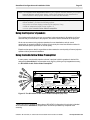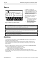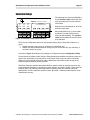
1
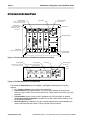
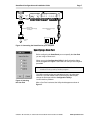
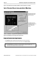
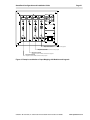
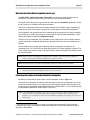
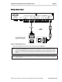
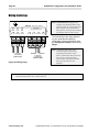
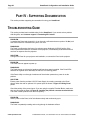
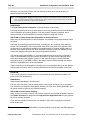
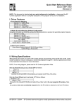
SmartPanel Configuration and Installation Guide
Page 57
Wiring Panel Power
GND
7B
7A
6B
6A
5B
5A
1
+12V DC
POWER
500mA MAX. CURRENT
SELECTION
(EXT. SWITCHER CTRL)
3
2
4B
4
4A
3B
PWR
OFF
MOM.
3A
2B
PWR
ON
MOM.
1B
SENSE
GND
IR/SER
+12V
CTS
PWR
ON
MAINT.
2A
RELAYS
IR/SERIAL
GND
RTS
TX
ACCESSORY
BUS
RX
AUDIO FOLLOW VIDEO
SWITCHER EXPANSION
RS232
1A
PROJECTOR CONTROL
CONFIGURATION
PORT
- OR -
CAUTION
"INDOOR USE
ONLY"
CAUTION
"INDOOR USE
ONLY"
This configuration can be used
when the power supply is
plugged in near the projector.
Figure 27: Wiring Panel power
Power can be applied to the Panel in two places as shown in Figure 27.
Note: Plugging the SmartPanel power supply in at the projector’s power receptacle (as shown
on the left in Figure 27) simplifies wire pulls, especially when using multi-conductor cable
for control. In the latter cases, Panel power and projector control are handled in a single
cable.
Note: The Panel requires power all the time. The Panel must be powered even when it appears
“off” to the user.
© 2002-8 SP Controls, Inc. 930 Linden Avenue South San Francisco CA 94080
www.spcontrols.com