1
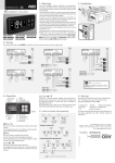
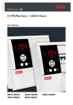
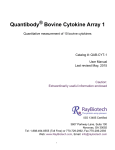
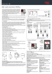
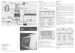
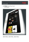
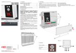
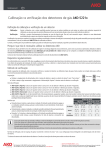
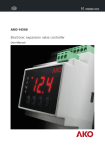
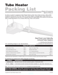
www.ako.com
1472H506 Ed.03
GB
-100ºC to +1000ºC 2 relay multi-sensor type electronic thermostats, formatted for 70.5 x 28.5 mm panel cut-out.
Menus, parameters and messages
Parameter transfer
Relay operation and control
Maintenance
Warnings
1- VERSIONS AND REFERENCES
MODEL
AKO-14725
AKO-14726
RELAYS
8 A, 250 V, cos ϕ=1, SPDT
8 A, 250 V, cos ϕ=1, SPDT
POWER SUPPLY, 50/60 Hz
120 V~ +8% -12%
230 V~ ±10%
TEMPERATURE
2- TECHNICAL DATA
Temperature range according to type of sensor supplied by AKO:
NTC (ntc). . . . . . . . . . . . . . . . . . . . . . . . . . . . . . -50.0 ºC to 105 ºC (-58.0 ºF to 221 ºF)
PTC (PtC) KTY type . . . . . . . . . . . . . . . . . . . . . -50.0 ºC to 150 ºC (-58.0 ºF to 302 ºF)
Pt 100 (Pt1) . . . . . . . . . . . . . . . . . . . . . . . . . . . . -100 ºC to 440 ºC (-148 ºF to 824 ºF)
J Thermocouple (JtC) . . . . . . . . . . . . . . . . . . . . . . . . . . 0 ºC to 600 ºC (32 ºF to 999 ºF)
K Thermocouple (HtC) . . . . . . . . . . . . . . . . . . . . . . . . . . 0 ºC to 999 ºC (32 ºF to 999 ºF)
Resolution, Set Point and differential (NTC, PTC, Pt 100): . . . . . . . . . . . . . . . . . . . . 0.1 ºC
Resolution, Set Point and differential (J or K thermocouple): . . . . . . . . . . . . . . . . . . . . 1 ºC
Thermometric accuracy (NTC, PTC, Pt 100): . . . . . . . . . . . . . . . . . . . . . . . . . . . . . . ± 1 ºC
Thermometric accuracy (J or K thermocouple): . . . . . . . . . . . . . . . . . . . . . . . . . . . . ± 2 ºC
Maximum input power: . . . . . . . . . . . . . . . . . . . . . . . . . . . . . . . . . . . . . . . . . . . . . . . 3 VA
Working ambient temperature: . . . . . . . . . . . . . . . . . . . . . . . . . . . . . . . . . . . 5 ºC to 50 ºC
Storage ambient temperature:. . . . . . . . . . . . . . . . . . . . . . . . . . . . . . . . . . -30 ºC to 70 ºC
Control device classification: Independent mounting, of Type 1.B action automatic operation characteristic, to be used in a clean situation, class A logical medium (software).
Double insulation between the power supply, secondary circuit and relay output.
Allocated pulse voltage: . . . . . . . . . . . . . . . . . . . . . . . . . . . . . . . . . . . . . . . . . . . . . 800 V
Pressure ball test temperature:
Accessible parts: . . . . . . . . . . . . . . . . . . . . . . . . . . . . . . . . . . . . . . . . . . . . . . . . . 75 ºC
Parts that position active elements: . . . . . . . . . . . . . . . . . . . . . . . . . . . . . . . . . . 125 ºC
Voltage and current declared by the EMC tests: . . . . . . . . . . . . . . . . . . . . . 207 V, 9 mA
3- INSTALLATION
The controller must be installed in a place protected from vibrations, water and corrosive
gases, and where ambient temperature does not surpass the value specified in the technical data.
In order for the controllers to have IP65 protection, the gasket must be properly installed
between the apparatus and the perimeter of the panel cut-out where it is to be fitted.
In order to give a correct reading, the sensor must be installed in a place without heat
influences other than the temperature that is to be measured or controlled.
3.1 Fastening units for panel mounting:
max. 18 mm
PANEL CUT-OUT
1
2
44
70,5
To fix the unit, place the fasteners 1 over the sliders 2 as shown
in the figure. Move the fasteners
in the direction of the arrow. By
pressing tab 3 fasteners may be
moved in the opposite direction of
the arrow.
Level 1 Menus
- Press + keys simultaneously for at least 10 seconds. The LED “PR” will start flashing, LEVEL 1 MENUS programming has been accessed and the first menu “Po1” is displayed.
- Press key to access the next menu and key to return to the previous one.
- Pressing + keys simultaneously in the last menu EP, the controller returns to the
CURRENT TEMPERATURE display status and LED “PR” will stop flashing.
When PA is displayed, the PASSWORD programmed in the PAr menu PAS parameter must
be entered to access LEVEL 1 MENUS programming.
- Press + keys simultaneously. 0 will be displayed to ENTER PASSWORD.
- Press or keys to CHANGE NUMBER and DISPLAY PASSWORD programmed.
- Press + keys simultaneously to ACCEPT PASSWORD. The first menu “Po1” will be
displayed.
Level 2 Parameters
- In the desired menu of LEVEL 1 MENUS, press keys
+
simultaneously. LEVEL 2
PARAMETERS programming is accessed. The first parameter of the selected menu is displayed on the screen.
- Press key to access the next parameter and key to return to the previous one.
- Pressing + keys simultaneously in the last parameter EP, the controller returns to
LEVEL 1 MENUS.
Level 3 Values
- To DISPLAY CURRENT VALUE of any parameter, select the required one and press +
keys simultaneously. Once it is displayed, you can CHANGE VALUE pressing or key.
- Press + keys simultaneously to ACCEPT THE NEW VALUE. The programming returns
to LEVEL 2 PARAMETERS.
CURRENT
TEMPERATURE
PASSWORD
IF PROGRAMMED
LEVEL 1
MENUS
LEVEL 2
PARAMETERS
LEVEL 3
VALUES
10 Sec.
SIMULTANEOUSLY
SIMULTANEOUSLY
61,5
3.2 Connection:
SIMULTANEOUSLY
SIMULTANEOUSLY
IF PAS=0
CURRENT
VALUE
SIMULTANEOUSLY
NEW
VALUE
ACCEPT
PASSWORD
SIMULTANEOUSLY
CHANGE
NUMBER
See diagram on the unit rating plate.
The sensor and its lead must NEVER be installed in ducting together with power, control or
power supply wiring.
The power supply circuit must be connected with a minimum 2 A, 230 V switch located
close to the unit. Power supply cables must be H05VV-F 2x0,5 mm2 or H05V-K 1x0,5 mm2 .
Section of connecting wires for relays contacts must range from 1 mm2 to 2.5 mm2.
SET POINT
5.2 Parameter configuration
DISPLAY
PARAMETER
28,5
3
SET POINT
ACCEPT
THE NEW
-
ACCEPT
THE NEW
6
7
8
9
10
CHANGE
VALUE
Versions and references
Technical data
Instalación
Front panel functions
Adjustment and configuration
The factory SET POINT default value is 0 ºC.
- Press key for at least 5 seconds to DISPLAY SET POINT in Relay R1 or key for Relay
R2. It displays the CURRENT SET POINT value and LED “PR” starts flashing.
- Press or keys to CHANGE SET POINT to the required value.
- Press
+
keys
simultaneously to
5 Sec. 5 Sec.
ACCEPT THE NEW
SET POINT. The disSIMULTANEOUSLY
play returns to the
CURRENT TEMPERATURE
display
status and LED
“PR” stops flashing.
CURRENT
CURRENT
NEW
CHANGE
SET POINT
-
5.1 Set Point temperature.
DISPLAY
VALUE
1
2
3
4
5
It must only be programmed or modified by personnel who are fully conversant with the
equipment operation and possibilities.
DISPLAY SP2
Relay R2
SET POINT
Index
5- ADJUSTMENT AND CONFIGURATION
DISPLAY SP1
Relay R1
SET POINT
Devices designed to display, control and regulate heating or cooling generators, with input
for NTC, PTC(KTY), Pt 100, J Thermocouple and K Thermocouple type sensors. Both outputs
with changeover relays can be configured for two independent stages, 2 related stages,
neutral zone, or also as 1 stage + alarm.
The complete technical information of the devices that appear in these basic instructions
is available in Data Sheet 1472H526 in our web www.ako.com.
4- FRONT PANEL FUNCTIONS
LED R1
LED ºF LED PR
ºF
UP key
PR
R1
R2
PRG
AL
LED AL
ºC
LED R2
DOWN key
UP key
Press once to cancel the alarms, but they
remain displayed (optional by parameter
AtA). When pressed for at least 5 seconds,
the SP1 Set Point temperature of Relay R1 is
displayed. In programming, it increases the
displayed value.
ENTER
PASSWORD
DISPLAY
PASSWORD
DOWN key
Press once to cancel the alarms, but they
remain displayed (optional by parameter AtA). When pressed for at least 5 seconds, the
SP2 Set Point temperature of Relay R2 is displayed. In programming, it decreases the
displayed value.
LED R1: Relay 1 indicator enabled
LED R2: Relay 2 indicator enabled
LED PR: Flashing, programming phase
PASSWORD
REQUEST
LED AL: Alarm indicator enabled
LED ºF: Degrees ºF indicator
EXIT
PROGRAMMING
EXIT TO
LEVEL 1
NOTE: If no key is pressed for 25 seconds in either of the previous steps, the controller will
automatically return to the CURRENT TEMPERATURE display status without modifying any
of the parameter values.
www.ako.com
6- MENUS, PARAMETERS AND MESSAGES
7- PARAMETER TRANSFER
Values in the Def. column are factory-set.
In programming, it must be taken into consideration that the parameters and values displayed depend on the option selected in the CFo configuration menu o2C parameter.
AKO-14918 portable server, with no power supply, in which parameters programmed in a
powered controller can be copied by transfer. Parameters can be transferred again from the
server to other identical
Power supply
powered controllers
AKO-14918
To transfer parameters,
other servers are available for controllers that
must be programmed
identically in high quanTransfer
tity without power
Programming
supply.
Level 1
Menus and Description
Po1 Level 2
R1 Relay Parameter Output
Level 3
Description
Values
di1 R1 and SP1 Differential (Hysteresis)
(ºC/ºF)
HL1 Set Point upper limit SP1 of R1
(ºC/ºF)
(It cannot be set above this value)
LL1 Set Point lower limit SP1 of R1
(ºC/ºF)
(It cannot be set below this value)
HC1 Type of operation R1: (0=Cold) (1=Heat)
Er1 R1 relay status with faulty sensor: 0=OFF 1=ON
EP Exit to Level 1
Po2 Level 2
R2 Relay Parameter Output
Level 3
Description
Values
di2 R2 and SP2 Differential (Hysteresis)
(ºC/ºF)
HL2 Set Point upper limit SP2 of R2
(ºC/ºF)
(It cannot be set above this value)
Set
Point
lower
limit
SP2
of
R2
LL2
(ºC/ºF)
(It cannot be set below this value)
HC2 Type of operation R2: (0=Cold) (1=Heat)
Er2 R2 relay status with faulty sensor: 0=OFF 1=ON
EP Exit to Level 1
CFo Level 2
Configuration Parameters
Level 3
Description
Values
R2 Relay output ratio type:
o2C (1=Two independent stages) (3=Neutral Zone)
(2=Two related stages) (4=1 Stage + alarm)
PbS Sensor type selection (Pt1, HtC, JtC, ntc, PtC)
CAn Sensor calibration (Offset)
(ºC/ºF)
Temperature display mode:
rES (0=Integers in ºC)
(1=A decimal in ºC) except in thermocouples
CFd Temperature display mode in ºC or ºF:
(0=ºC) (1=ºF)
toF Delay time for the relays to switch ON
(sec.)
ton Delay time for the relays to switch OFF
(sec.)
EP Exit to Level 1
ALA Level 2
Alarm Parameters
Level 3
Description
Values
ACo Alarm configuration:
0
(0=Absolute) (1=Related to set point SP1 of R1)
ALt Minimum alarm: (Limited by AHt)
(ºC/ºF)
AHt Maximum alarm: (Limited by ALt)
(ºC/ºF)
Adi Alarm differential
(ºC/ºF)
AdE Alarm delay from the moment at which they must be enabled (min)
Ado Alarm delay at start-up
(min)
Arc Polarity configuration of the alarm relay:
(0=In the event of an alarm, relay ON) (1=In the event of an alarm, relay OFF)
Optional cancellation of output alarms
by pressing once a key:
AtA (0 = Allows to cancel the output alarms)
(1 = Not allows to cancel the output alarms)
EP Exit to Level 1
InP Level 2
Digital Input Parameters
Level 3
Description
Values
Digital input configuration: (0=Disabled)
ICF (1=External alarm) (2=R1 Relay set point SP1 variation)
(3=Inversion type of operation HC1)
IPo Digital output status inversion:
(0=Closed Contact) (1=Open Contact)
IdY Digital input enabling delay
(min)
USI R1 Relay set point SP1 variation if ICF=2
(ºC/ºF)
tSI USI variation length
(min)
EP Exit to Level 1
PAr Level 2
General Parameters
Level 3
Description
Values
CYt R1 Relay output switching off frequency
(h)
oFt R1 Relay output switching off time
(min)
PdE Initial parameters:
(1=YES, configure to “Def” and exit programming)
Ptr Transfer parameters:
(0=Disabled) (1=Send) (2=Receive)
PAS Password to parameters and information
CAd Address for units with communication
PU Programme version (Information)
EP Exit to Level 1
EP Exit programming
Min. Def. Max.
-50 1
50
LL1 999 999
-99
0
0
-99 HL1
1
0
1
1
8- R1 AND R2 RELAY OPERATION AND CONTROL
SP1 = R1 Relay set point
Min. Def. Max.
-50 1
50
LL2 999 999
-99
0
0
-99 HL2
1
0
1
1
o2C = 1 Two independent stage
Operation for HEAT
Operation for COLD
HC1 = 1 for R1 Relay
1
1
20
0
0
1
0
0
1
0
0
0
0
250
250
di2 > 0
R1
ON
SP2
Start
di2 < 0
R2
R1
R2
SP2
Stop
TEMP.
SP2+di2
Start
di2 < 0
R1
SP2-di2
Start
SP1
Stop
SP2
Stop
SP1+di1
Start
di1 < 0
R2
SP1-di1
Stop
SP2-di2
Stop
SP1
Start
SP2
Start
TEMP.
o2C = 2 Two related stages
Operation for COLD
Operation for HEAT
HC1 = 0 di1 > 0 SP2 > 0
ON
R1
R2
OFF
SP1-SP2-di1
Start
SP1-di1
Start
SP1 - SP2
Stop
TEMP.
SP1
Stop
Min. Def. Max.
0
ON
1
R1
-99 -99 AHt
ALt 999 999
1
1
20
0
0 250
0
0 250
0
0
R2
OFF
SP1
Stop
SP1+SP2 SP1+SP2+di1
Stop
Start
SP1+di1
Start
TEMP.
o2C = 3 Neutral Zone
ON
1
R1
OFF
0
0
SP1-di1
Start
1
SP1
Stop
TEMP.
ON
R2
OFF
SP1
Stop
Min. Def. Max.
0
0
3
0
0
1
0
-99
0
0
0
0
120
999
254
SP1+di1 TEMP.
Start
o2C = 4 1 Stage + alarm
Operation for HEAT
Operation for COLD
HC1 = 0 for R1 Relay
HC1 = 1 for R1 Relay
ON
0
1
0
0
2
0
0
0
0
250
250
di1 > 0
ON
R1
R1
OFF
OFF
SP1
Start
SP1+di1 TEMP.
Stop
SP1
Stop
di1 < 0
ON
Min. Def. Max.
0
6 120
0
0 120
0
di1 > 0
SP1+di1
Start
TEMP.
di1 < 0
ON
R1
R1
OFF
OFF
SP1-di1
Start
TEMP.
SP1
Stop
SP1-di1
Stop
With alarm R2 relay ON if Arc = 0
TEMP.
SP1
Start
With alarm R2 relay OFF if Arc = 1
ON
ON
R2
OFF
If ACo = 0
If ACo = 1
ALt
SP1+ALt
Start
ALt+Adi
SP1+ALt+Adi
Stop
R2
AHt-Adi
SP1+AHt-Adi
Stop
R2
AHt
SP1+AHt
Start
TEMP.
ACo is the alarm configuration parameter
OFF
If ACo = 0
If ACo = 1
ALt
SP1+ALt
Stop
ALt+Adi
SP1+ALt+Adi
Start
R2
AHt-Adi
AHt
SP1+AHt -Adi SP1+AHt
Start
Stop
TEMP.
ACo is the alarm configuration parameter
9- MAINTENANCE
Clean the controller surface with a soft cloth, soap and water. Do not use abrasive detergents, petrol, alcohol or solvents.
10- WARNINGS
NOTE: When the time and alarm parameters are modified, the new values are applied when
the current cycle is completed. In order for it to have an immediate effect, switch the controller off and then on again.
AKO ELECTROMECÀNICA, S.A.L.
D.L.: B - 46.867 - 04
351472506 REV.02
di2 > 0
R1
SP1
Stop
SP2+di2
Stop
HC1 = 1 di1 < 0 SP2 < 0
MESSAGES
AH The Sensor temperature exceeds the parameter programmed in AHt
AL The Sensor temperature is lower than the parameter programmed in ALt
EAL Active digital input
E1 Sensor failure (Open circuit, crossed, out-of-scale temperature)
- - - Temperature > 999 ºF/ºC
EE Memory failure
PA Password request to access programming parameters
Nos reservamos el derecho de suministrar materiales que
pudieran diferir levemente de los descritos en nuestras Hojas
Técnicas. Información actualizada en nuestra web: www.ako.com.
HC2 = 0 for R2 Relay
di1 > 0
R2
SP1+di1
Stop
di1 < 0
OFF
SP1-di1
Start
Pt1
0
HC1 = 0 for R1 Relay
OFF
4
-20
HC2 = 1 for R2 Relay
di1 > 0
ON
SP1
Start
Min. Def. Max.
SP2 = R2 Relay set point
2005
The use of the unit without observing the manufacturer’s instructions may alter its safety
qualification.
To ensure correct operation of the apparatus, only sensors supplied by AKO must be used.
Av. Roquetes, 30-38
08812 Sant Pere de Ribes (Barcelona)
e-mail: [email protected]
Tel. (34) 938 142 700 Fax (34) 938 934 054
Apartado (P.O. Box), 5
08800 Vilanova i la Geltrú (Spain)